
You also want an ePaper? Increase the reach of your titles
YUMPU automatically turns print PDFs into web optimized ePapers that Google loves.
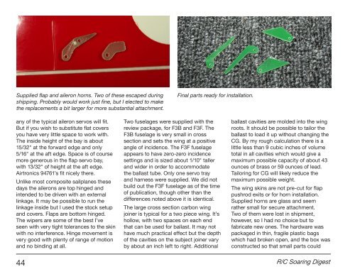
Supplied flap and aileron horns. Two of these escaped during<br />
shipping. Probably would work just fine, but I elected to make<br />
the replacements a bit larger for more substantial attachment.<br />
Final parts ready for installation.<br />
any of the typical aileron servos will fit.<br />
But if you wish to substitute flat covers<br />
you have very little space to work with.<br />
The inside height of the bay is about<br />
15/32" at the forward edge and only<br />
5/16" at the aft edge. Space is of course<br />
more generous in the flap servo bay,<br />
with 13/32" of height at the aft edge.<br />
Airtronics 94761’s fit nicely there.<br />
Unlike most composite sailplanes these<br />
days the ailerons are top hinged and<br />
intended to be driven with an external<br />
linkage. It may be possible to run the<br />
linkage inside but I used the stock setup<br />
and covers. Flaps are bottom hinged.<br />
The wipers are some of the best I’ve<br />
seen with very tight tolerances to the skin<br />
with no interference. Hinge movement is<br />
very good with plenty of range of motion<br />
and no binding at all.<br />
Two fuselages were supplied with the<br />
review package, for F3B and F3F. The<br />
F3B fuselage is very small in cross<br />
section and sets the wing at a positive<br />
angle of incidence. The F3F fuselage<br />
appears to have zero-zero incidence<br />
settings and is sized about 1/10" taller<br />
and wider in order to accommodate<br />
the ballast tube. Only one servo tray<br />
and harness were supplied. We did not<br />
build out the F3F fuselage as of the time<br />
of publication, though other than the<br />
differences noted above it is identical.<br />
The large cross section carbon wing<br />
joiner is typical for a two piece wing. It’s<br />
hollow, with two spaces on each end<br />
that can be used for ballast. It may not<br />
have much practical effect but the depth<br />
of the cavities on the subject joiner vary<br />
by about an inch left to right. Additional<br />
ballast cavities are molded into the wing<br />
roots. It should be possible to tailor the<br />
ballast to load it up without changing the<br />
CG. By my rough calculation there is a<br />
little less than 9 cubic inches of volume<br />
total in all cavities which would give a<br />
maximum possible capacity of about 43<br />
ounces of brass or 59 ounces of lead.<br />
Tailoring for CG will likely reduce the<br />
maximum possible weight.<br />
The wing skins are not pre-cut for flap<br />
pushrod exits or for horn installation.<br />
Supplied horns are glass and seem<br />
rather small for secure attachment.<br />
Two of them were lost in shipment,<br />
however, so I had no choice but to<br />
fabricate new ones. The hardware was<br />
packaged in thin, fragile plastic bags<br />
which had broken open, and the box was<br />
constructed so that small parts could<br />
44 R/C <strong>Soaring</strong> <strong>Digest</strong>