SDH Major Operational Components Summary ... - Christiealwis.com
SDH Major Operational Components Summary ... - Christiealwis.com
SDH Major Operational Components Summary ... - Christiealwis.com

Create successful ePaper yourself
Turn your PDF publications into a flip-book with our unique Google optimized e-Paper software.
<strong>SDH</strong> <strong>Major</strong> <strong>Operational</strong><br />
<strong>Components</strong><br />
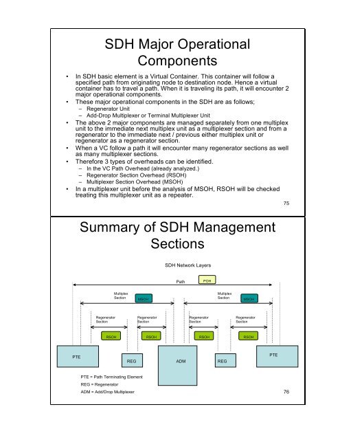
• In <strong>SDH</strong> basic element is a Virtual Container. This container will follow a<br />
specified path from originating node to destination node. Hence a virtual<br />
container has to travel a path. When it is traveling its path, it will encounter 2<br />
major operational <strong>com</strong>ponents.<br />
• These major operational <strong>com</strong>ponents in the <strong>SDH</strong> are as follows;<br />
– Regenerator Unit<br />
– Add-Drop Multiplexer or Terminal Multiplexer Unit<br />
• The above 2 major <strong>com</strong>ponents are managed separately from one multiplex<br />
unit to the immediate next multiplex unit as a multiplexer section and from a<br />
regenerator to the immediate next / previous either multiplex unit or<br />
regenerator as a regenerator section.<br />
• When a VC follow a path it will encounter many regenerator sections as well<br />
as many multiplexer sections.<br />
• Therefore 3 types of overheads can be identified.<br />
– In the VC Path Overhead (already analyzed.)<br />
– Regenerator Section Overhead (RSOH)<br />
– Multiplexer Section Overhead (MSOH)<br />
• In a multiplexer unit before the analysis of MSOH, RSOH will be checked<br />
treating this multiplexer unit as a repeater.<br />
75<br />
<strong>Summary</strong> of <strong>SDH</strong> Management<br />
Sections<br />
<strong>SDH</strong> Network Layers<br />
Path<br />
POH<br />
Multiplex<br />
Section<br />
MSOH<br />
Multiplex<br />
Section<br />
MSOH<br />
Regenerator<br />
Section<br />
Regenerator<br />
Section<br />
Regenerator<br />
Section<br />
Regenerator<br />
Section<br />
RSOH RSOH RSOH RSOH<br />
PTE<br />
REG<br />
ADM<br />
REG<br />
PTE<br />
PTE = Path Terminating Element<br />
REG = Regenerator<br />
ADM = Add/Drop Multiplexer<br />
76
• Regenerator Section Overhead<br />
– The Regenerator Section Overhead contains only the information<br />
required for the elements located at both ends of a section.<br />
– The Regenerator Section Overhead is found in the first three rows of<br />
Columns 1 through 9 x N of the STM-N, N ≥ 1 frame.<br />
• Multiplex Section Overhead<br />
– The Multiplex Section Overhead contains the information required<br />
between the multiplexer section termination equipment at each end of<br />
the Multiplex section.<br />
– The Multiplex Section Overhead is found in Rows 5 to 9 of Columns 1<br />
through 9 x N of the STM-N, N ≥ 1 frame.<br />
• Path Overhead<br />
– Discussed earlier<br />
77<br />
9 rows<br />
*<br />
∆<br />
STM-1 Regenerator section overhead (RSOH) &<br />
Multiplex Section Overhead (MSOH)<br />
A1<br />
B1<br />
D1<br />
B2<br />
D4<br />
D7<br />
D10<br />
S1<br />
A1<br />
∆<br />
∆<br />
A1 A2 A2 A2<br />
∆<br />
∆<br />
E1<br />
D2<br />
B2 B2 K1<br />
D5<br />
D8<br />
D11<br />
9 bytes<br />
∆<br />
∆<br />
J0<br />
F1<br />
D3<br />
Administrative Unit pointer(s)<br />
Unscrambled bytes<br />
K2<br />
D6<br />
D9<br />
D12<br />
M1 E2<br />
Bytes reserved for national use<br />
*<br />
*<br />
T1543290-01<br />
RSOH<br />
MSOH<br />
The content of these reserved bytes has to be carefully<br />
selected as they are not scrambled.<br />
Media-dependent bytes<br />
NOTE – All unmarked bytes are reserved for future international standardization<br />
(for media-dependent, additional national use and other purposes).<br />
• A1 and A2 - Framing<br />
• J0 - Regenerator Section (RS) Trace<br />
message<br />
• B1 - RS bit interleaved parity code (BIP-<br />
8) byte<br />
• E1 - RS orderwire byte<br />
• F1- RS user channel byte<br />
• D1, D2, D3 - RS Data Communications<br />
Channel (DCC) bytes<br />
• B2 - Multiplex Section (MS) bit interleaved<br />
parity code (MS BIP-24) byte<br />
• K1 & K2 - Automatic Protection Switching<br />
(APS channel) bytes<br />
• D4 to D12 - MS Data Communications<br />
Channel (DCC) bytes S1- Synchronization<br />
status message byte (SSMB)<br />
• M1- MS remote error indication<br />
• E2 - MS orderwire byte<br />
78<br />
2
Regenerator Section Overhead<br />
• A1 and A2 - Framing bytes – These two bytes indicate the beginning of the STM-N<br />
frame. The A1, A2 bytes are unscrambled. A1 has the binary value 11110110, and A2<br />
has the binary value 00101000. The frame alignment word of an STM-N frame is<br />
<strong>com</strong>posed of (3 x N) A1 bytes followed by (3 x N) A2 bytes.<br />
• J0 - Regenerator Section (RS) Trace message – It’s used to transmit a Section Access<br />
Point Identifier so that a section receiver can verify its continued connection to the<br />
intended transmitter. The coding of the J0 byte is the same as for J1 and J2 bytes.<br />
• Z0 - These bytes, which are located at positions in STM-N signal (N > 1), are reserved<br />
for future international standardization.<br />
• B1 - RS bit interleaved parity code (BIP-8) byte – This is a parity code (even parity),<br />
used to check for transmission errors over a regenerator section. Its value is calculated<br />
over all bits of the previous STM-N frame after scrambling, then placed in the B1 byte<br />
of STM-1 before scrambling.<br />
• E1 - RS orderwire byte – This byte is allocated to be used as a local order wire channel<br />
for voice <strong>com</strong>munication between regenerators.<br />
• F1- RS user channel byte – This byte is set aside for the user’s purposes; it can be read<br />
and/or written to at each section terminating equipment in that line.<br />
• D1, D2, D3 - RS Data Communications Channel (DCC) bytes – These three bytes<br />
form a 192 kbit/s message channel providing a message-based channel for Operations,<br />
Administration and Maintenance (OAM) between pieces of section terminating<br />
equipment. The channel can be used from a central location for control, monitoring,<br />
administration, and other <strong>com</strong>munication needs.<br />
79<br />
Multiplex Section Overhead<br />
• B2 - Multiplex Section (MS) bit interleaved parity code (MS BIP-24) byte – This bit<br />
interleaved parity N x 24 code is used to determine if a transmission error has occurred over a<br />
multiplex section. It’s even parity, and is calculated overall bits of the MS Overhead and the<br />
STM-N frame of the previous STM-N frame before scrambling.<br />
• K1 and K2 - Automatic Protection Switching (APS channel) bytes – These two bytes are used<br />
for MSP (Multiplex Section Protection) signaling between multiplex level entities for bidirectional<br />
automatic protection switching and for <strong>com</strong>municating Alarm Indication Signal<br />
(AIS) and Remote Defect Indication (RDI) conditions.<br />
K1 Byte<br />
K2 Byte<br />
Bits 1-4 Type of request Bits 1-4 Selects channel number<br />
– 1111 Lock out of Protection Bit 5 Indication of architecture<br />
– 1110 Forced Switch 0 1+1<br />
– 1101 Signal Fail – High Priority 1 1:n<br />
– 1100 Signal Fail – Low Priority Bits 6-8 Indicate mode of operation<br />
– 1011 Signal Degrade – High Priority 111 MS-AIS<br />
– 1010 Signal Degrade – Low Priority 110 MS-RDI<br />
– 1001 (not used) 101 Provisioned mode is bi-directional<br />
– 1000 Manual Switch 100 Provisioned mode is unidirectional<br />
– 0111 (not used) 011 Future use<br />
– 0110 Wait-to-Restore 010 Future use<br />
– 0101 (not used) 001 Future use<br />
– 0100 Exercise 000 Future use<br />
– 0011 (not used)<br />
– 0010 Reverse Request<br />
– 0001 Do Not Revert<br />
– 0000 No Request<br />
Bits 5-8 Indicate the number of the channel requested<br />
80<br />
3
Multiplex Section Overhead (contd.)<br />
• D4 to D12 - MS Data Communications Channel (DCC) bytes – These nine bytes<br />
form a 576 kbit/s message channel from a central location for OAM information.<br />
• S1- Synchronization status message byte (SSMB) – Bits 5 to 8 of this S1 byte are<br />
used to carry the synchronization messages.<br />
Bits 5-8<br />
• 0000 Quality unknown (existing sync.network)<br />
• 0010 G.811 PRC<br />
• 0100 SSU-A (G.812 transit)<br />
• 1000 SSU-B (G.812 local)<br />
• 1011 G.813 Option 1 Synchronous Equipment Timing Clock (SEC)<br />
• 1111 Do not use for synchronization.This message may be emulated by equipment failures and will be<br />
emulated by a Multiplex Section AIS signal.<br />
• M1- MS remote error indication – The M1 byte of an STM-1 or the first STM-1 of<br />
an STM-N is used for a MS layer remote error indication (MS-REI).<br />
• E2 - MS orderwire byte – This orderwire byte provides a 64 kbit/s channel between<br />
multiplex entities for an express orderwire.<br />
81<br />
Automatic Protection Switching<br />
(APS)<br />
• Automatic Protection Switching (APS) is the<br />
capability of a transmission system to detect a failure<br />
on a working facility and to switch to a standby<br />
facility to recover the traffic.<br />
• This capability has a positive effect on the overall<br />
system availability.<br />
• Two modes of APS are provided:<br />
– 1+1 protection switching<br />
– 1:N protection switching.<br />
82<br />
4
1+1 Protection Switching<br />
1+ N Protection Switching<br />
83<br />
<strong>Summary</strong> of <strong>SDH</strong> Mapping, Aligning, Pointer processing &<br />
Multiplexing<br />
C-4 VC-4 AU-4<br />
STM-1<br />
x 3<br />
x 1<br />
C-3 VC-3<br />
TU-3 TUG-3<br />
x 7<br />
x 3<br />
C-12 VC-12 TU-12 TUG-2<br />
Pointer processing<br />
Multiplexing<br />
Aligning<br />
Mapping<br />
84<br />
5
VC-3 Structure<br />
When mapped by 34Mbps or 44Mbps<br />
J1<br />
1<br />
2<br />
..<br />
..<br />
84<br />
B3<br />
C2<br />
G1<br />
F2<br />
C-3<br />
H4<br />
F3<br />
K3<br />
N1<br />
1<br />
..<br />
..<br />
..<br />
..<br />
85<br />
VC-3 POH<br />
85<br />
TUG-3 Structure<br />
When mapped by 34Mbps or 44Mbps<br />
H1<br />
J1<br />
1<br />
2<br />
..<br />
..<br />
84<br />
H2<br />
B3<br />
H3<br />
C2<br />
G1<br />
F2<br />
H4<br />
F3<br />
K3<br />
N1<br />
1<br />
TU-3 Pointer<br />
2<br />
Spare bits<br />
..<br />
..<br />
..<br />
..<br />
86<br />
86<br />
6
TUG-3 structure<br />
87<br />
When mapped from lower order<br />
TUG-3 Structure<br />
1<br />
2<br />
..<br />
..<br />
84<br />
1<br />
2<br />
..<br />
..<br />
..<br />
..<br />
86<br />
* - no POH are added at VC3, but the<br />
individual POHs will be carried by each<br />
lower order container, i.e. VC12<br />
Spare bits<br />
88<br />
7
When mapped from TUG3:<br />
Structure of VC4<br />
TUG x 3 (A,B,C)= AU4<br />
A<br />
B<br />
C<br />
P<br />
P<br />
P<br />
A<br />
B<br />
C<br />
A<br />
B<br />
C<br />
A<br />
B<br />
C<br />
..<br />
..<br />
..<br />
..<br />
..<br />
A<br />
B<br />
C<br />
O<br />
O<br />
O<br />
H<br />
H<br />
H<br />
A<br />
B<br />
C<br />
1<br />
2<br />
3<br />
4<br />
..<br />
..<br />
..<br />
..<br />
..<br />
..<br />
..<br />
..<br />
..<br />
..<br />
..<br />
..<br />
..<br />
..<br />
..<br />
..<br />
..<br />
261 ..<br />
Spare bits<br />
89<br />
When mapped from VC4:<br />
Structure of AU4<br />
P<br />
O<br />
H<br />
H1<br />
Y<br />
Y<br />
H2<br />
H2<br />
H2<br />
H3<br />
H3<br />
H3<br />
C - 4<br />
9<br />
1<br />
2<br />
3<br />
4<br />
..<br />
..<br />
..<br />
..<br />
..<br />
..<br />
..<br />
..<br />
..<br />
258<br />
.<br />
.<br />
..<br />
..<br />
..<br />
..<br />
..<br />
..<br />
..<br />
90<br />
..<br />
26<br />
1<br />
8