Introduction to Servo Motors & Arduino - Arduino Egypt
Introduction to Servo Motors & Arduino - Arduino Egypt
Introduction to Servo Motors & Arduino - Arduino Egypt

Create successful ePaper yourself
Turn your PDF publications into a flip-book with our unique Google optimized e-Paper software.
<strong>Servo</strong> Mo<strong>to</strong>rs Control & <strong>Arduino</strong><br />
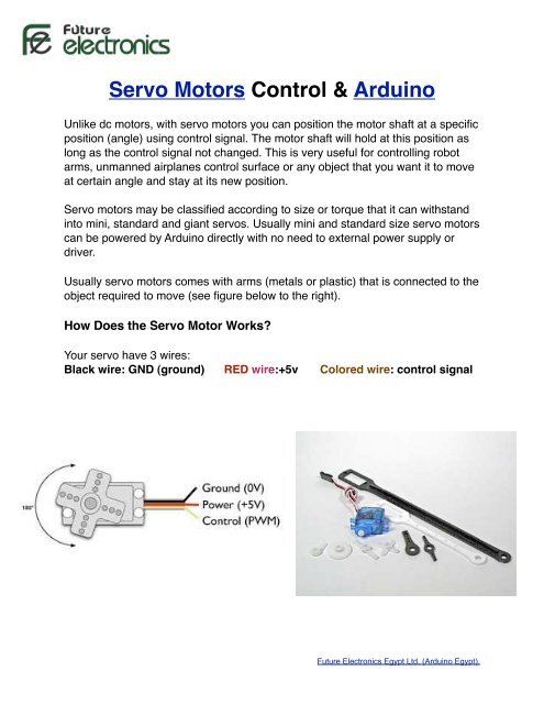
Unlike dc mo<strong>to</strong>rs, with servo mo<strong>to</strong>rs you can position the mo<strong>to</strong>r shaft at a specific<br />
position (angle) using control signal. The mo<strong>to</strong>r shaft will hold at this position as<br />
long as the control signal not changed. This is very useful for controlling robot<br />
arms, unmanned airplanes control surface or any object that you want it <strong>to</strong> move<br />
at certain angle and stay at its new position.<br />
<strong>Servo</strong> mo<strong>to</strong>rs may be classified according <strong>to</strong> size or <strong>to</strong>rque that it can withstand<br />
in<strong>to</strong> mini, standard and giant servos. Usually mini and standard size servo mo<strong>to</strong>rs<br />
can be powered by <strong>Arduino</strong> directly with no need <strong>to</strong> external power supply or<br />
driver.<br />
Usually servo mo<strong>to</strong>rs comes with arms (metals or plastic) that is connected <strong>to</strong> the<br />
object required <strong>to</strong> move (see figure below <strong>to</strong> the right).<br />
How Does the <strong>Servo</strong> Mo<strong>to</strong>r Works?<br />
Your servo have 3 wires:<br />
Black wire: GND (ground) ! RED wire:+5v !<br />
Colored wire: control signal<br />
Future Electronics <strong>Egypt</strong> Ltd. (<strong>Arduino</strong> <strong>Egypt</strong>).
The third pin accept the control signal which is a pulse-width modulation (PWM)<br />
signal. It can be easily produced by all micro- controllers and <strong>Arduino</strong> board.<br />
This accepts the signal from your controller that tells it what angle <strong>to</strong> turn <strong>to</strong>. The<br />
control signal is fairly simple compared <strong>to</strong> that of a stepper mo<strong>to</strong>r. It is just a<br />
pulse of varying lengths. The length of the pulse corresponds <strong>to</strong> the angle the<br />
mo<strong>to</strong>r turns <strong>to</strong>.<br />
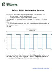
For detailed and simplified explanation of Pulse Width Modulation (PWM),<br />
Please click here.<br />
The pulse width sent <strong>to</strong> servo ranges as follows:<br />
Minimum: 1 millisecond ---> Corresponds <strong>to</strong> 0 rotation angle.<br />
Maximum: 2 millisecond ---> Corresponds <strong>to</strong> 180 rotation angle.<br />
Any length of pulse in between will rotate the servo shaft <strong>to</strong> its corresponding<br />
angle. For example, 1.5 ms pulse corresponds <strong>to</strong> rotation angle of 90 degree.<br />
This is will explained in figure below.<br />
Figure 8-2. Relationship between the pulse width and the servo angle; the servo output arm moves<br />
proportionally as the pulse width increases from 1 ms <strong>to</strong> 2 ms<br />
The primary characteristic in selecting a mo<strong>to</strong>r is <strong>to</strong>rque. Torque determines how much<br />
work the mo<strong>to</strong>r can do. Typically, higher <strong>to</strong>rque mo<strong>to</strong>rs are larger and heavier and<br />
draw more current than lower <strong>to</strong>rque mo<strong>to</strong>rs.<br />
Future Electronics <strong>Egypt</strong> Ltd. (<strong>Arduino</strong> <strong>Egypt</strong>).
Inside the <strong>Servo</strong> Mo<strong>to</strong>r<br />
Did ever wonder how the servo mo<strong>to</strong>rs looks from inside?. Have a look at the<br />
corresponding picture. A servo mo<strong>to</strong>r was taken apart <strong>to</strong> show the internal parts.<br />
You can see a regular dc mo<strong>to</strong>r connected <strong>to</strong> a gear box and a potentiometer that<br />
give the feed back for angle position.<br />
This is represented by the diagram below.<br />
Future Electronics <strong>Egypt</strong> Ltd. (<strong>Arduino</strong> <strong>Egypt</strong>).
Mo<strong>to</strong>r Control Using <strong>Arduino</strong><br />
Standard servo mo<strong>to</strong>r control using <strong>Arduino</strong> is extremely easy. This is<br />
because the <strong>Arduino</strong> software comes with a sample servo sketch and servo<br />
library that will get you up and running quickly<br />
1. Connect the black wire from the servo <strong>to</strong> the Gnd pin on the <strong>Arduino</strong><br />
2. Connect the red wire from the servo <strong>to</strong> the +5V pin on the <strong>Arduino</strong><br />
3. Connect the third wire (usually orange or yellow) from the servo <strong>to</strong> a digital<br />
pin on the <strong>Arduino</strong><br />
Figure 8-3. Connecting a servo for testing with the example Sweep sketch<br />
Discussion<br />
This example sweeps the servo between 0 and 180 degrees. You may need <strong>to</strong> tell the<br />
library <strong>to</strong> adjust the minimum and maximum positions so that you get the range of<br />
movement you want. Calling <strong>Servo</strong>.attach with optional arguments for minimum and<br />
maximum positions will adjust the movement:<br />
myservo.attach(9,1000,2000 ); // use pin 9, set min <strong>to</strong> 1000us, max <strong>to</strong> 2000us<br />
Because typical servos respond <strong>to</strong> pulses measured in microseconds and not degrees,<br />
the arguments following the pin number inform the <strong>Servo</strong> library how many microseconds<br />
<strong>to</strong> use when 0 degrees or 180 degrees are requested. Not all servos will move<br />
over a full 180-degree range, so you may need <strong>to</strong> experiment with yours <strong>to</strong> get the range<br />
you want.<br />
The parameters for servo.attach(pin, min, max) are the following:<br />
pin<br />
The pin number that the servo is attached <strong>to</strong> (must be 9 or 10)<br />
min (optional)<br />
The pulse width, in microseconds, corresponding <strong>to</strong> the minimum (0-degree) angle<br />
on the servo (defaults <strong>to</strong> 544)<br />
Future Electronics <strong>Egypt</strong> Ltd. (<strong>Arduino</strong> <strong>Egypt</strong>).<br />
max (optional)<br />
The pulse width, in microseconds, corresponding <strong>to</strong> the maximum (180-degree)
Important Notes:<br />
1- It is not a good idea <strong>to</strong> connect a mo<strong>to</strong>r of any kind directly <strong>to</strong> the <strong>Arduino</strong><br />
because it usually requires more power than the board can provide.<br />
2- In our example, the servo is being used <strong>to</strong> demonstrate code and is not<br />
encountering any resistance. Note that you should use a standard or small size<br />
if you are uncertain, check the servo's no load current rating (it should usually be<br />
under 150mA).<br />
3-You may need an external source of 5 or 6 volts when connecting multiple<br />
servos. Four AA cells work well if you want <strong>to</strong> use battery power. Remember that<br />
you must connect the ground of the external power source <strong>to</strong> <strong>Arduino</strong> ground.<br />
Here is the example Sweep sketch distributed with <strong>Arduino</strong>;:<br />
#include <br />
<strong>Servo</strong> myservo; // create servo object <strong>to</strong> control a servo<br />
int angle = 0; // variable <strong>to</strong> s<strong>to</strong>re the servo position<br />
void setup() {<br />
264<br />
| Chapter 8: Physical Output<br />
}<br />
myservo.attach(9); // attaches the servo on pin 10 <strong>to</strong> the servo object<br />
void loop() {<br />
}<br />
for(angle = 0; angle < 180; angle += 1) // goes from 0 degrees <strong>to</strong> 180 degrees<br />
{<br />
myservo.write(angle); delay(20);<br />
// in steps of 1 degree // tell servo <strong>to</strong> go <strong>to</strong> position in variable 'angle' // waits 20ms<br />
between servo commands<br />
} for(angle = 180; angle >= 1; angle -= 1) // goes from 180 degrees <strong>to</strong> 0 degrees {<br />
}<br />
myservo.write(pos); delay(20);<br />
// tell servo <strong>to</strong> go <strong>to</strong> position in variable 'pos' // waits 20ms between servo<br />
commands<br />
Future Electronics <strong>Egypt</strong> Ltd. (<strong>Arduino</strong> <strong>Egypt</strong>).
Controlling <strong>Servo</strong>s with a Potentiometer or Sensor<br />
This can be used for example if you want <strong>to</strong> control the pan and tilt of a camera<br />
or sensor connected <strong>to</strong> the servos. It is almost the same code like the above<br />
example with the addition of code <strong>to</strong> read the voltage on a potentiometer. This<br />
value is scaled so that the position of the pot (from 0 <strong>to</strong> 1023) is mapped <strong>to</strong> a<br />
value between 0 and 180 degrees. The only difference in the wiring is the<br />
addition of the potentiometer; please see figure below for hardware connection<br />
<strong>Arduino</strong> Sketch:<br />
Figure 8-4. Controlling a servo with a potentiometer<br />
#include Discussion <strong>Servo</strong> myservo; // create servo object <strong>to</strong> control a servo<br />
int potpin = 0; // analog pin used <strong>to</strong> connect the potentiometer<br />
Anything that can be read from analogRead (see Chapter 5 and Chapter 6) can be used—<br />
int val;! for // example, variable the <strong>to</strong> gyro read and the accelerometer value from recipes the in analog Chapter 6 pin can be used so that the<br />
void setup() angle of the servo is controlled by the yaw of the gyro or angle of the accelerometer.<br />
{<br />
myservo.attach(9); 8.3 Controlling // attaches the Speed the of servo Continuous pin 9 Rotation <strong>to</strong> the servo <strong>Servo</strong>s object<br />
}<br />
void loop() Problem<br />
{ You want <strong>to</strong> control the rotational direction and speed of servos modified for continuous<br />
rotation. For example,<br />
val = analogRead(potpin); !<br />
you are<br />
!<br />
using<br />
//<br />
two<br />
reads<br />
continuous<br />
the value<br />
rotation<br />
of the<br />
servos<br />
potentiometer<br />
<strong>to</strong> power a<br />
robot and you want the speed and direction <strong>to</strong> be controlled by your sketch.<br />
val = map(val, 0, 1023, 0, 179);!! ! // scale it <strong>to</strong> use it with the<br />
servo! Solution<br />
myservo.write(val);! Continuous rotation ! servos ! are a form ! of // gear sets reduced position mo<strong>to</strong>r <strong>to</strong> with the forward scaled and value backward<br />
speed ! adjustment. ! ! Control ! // of waits continuous for the rotation servo servos <strong>to</strong> get is similar there <strong>to</strong> normal<br />
delay(15);!<br />
}<br />
servos. The servo rotates in one direction as the angle is increased from 90 degrees; it<br />
rotates in the other direction when the angle is decreased from 90 degrees. The actual<br />
direction forward or backward depends on how you have the servos attached. Figure<br />
8-5 shows the connections for controlling two servos.<br />
Future Electronics <strong>Egypt</strong> Ltd. (<strong>Arduino</strong> <strong>Egypt</strong>).<br />
This example sweeps the servos from 90 <strong>to</strong> 180 degrees, so if the servos were connected<br />
<strong>to</strong> wheels, the vehicle would move forward at a slowly increasing pace and then slow