OPV-iR-X-CAM reverse camera interface. LR2 is not ... - Nav-TV
OPV-iR-X-CAM reverse camera interface. LR2 is not ... - Nav-TV
OPV-iR-X-CAM reverse camera interface. LR2 is not ... - Nav-TV

You also want an ePaper? Increase the reach of your titles
YUMPU automatically turns print PDFs into web optimized ePapers that Google loves.
<strong>OPV</strong>-ir-X-<strong>CAM</strong> 09/19/2011 Derek Schmiedl<br />
100 NW 11th ST, Boca Raton, FL 33432<br />
Tel. 1-866-477-3336 Fax. 1-561-955-9760<br />
sales@nav-tv.com www.nav-tv.com<br />
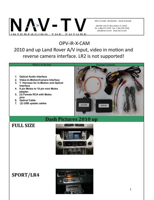
<strong>OPV</strong>-<strong>iR</strong>-X-<strong>CAM</strong><br />
<strong>reverse</strong> <strong>camera</strong> <strong>interface</strong>. <strong>LR2</strong> <strong>is</strong> <strong>not</strong> supported!<br />
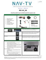
What’s in the box<br />
Package Contents<br />
4)<br />
3)<br />
1. Optical Audio Interface<br />
2. Video-In-Motion/Camera Interface<br />
3. T - Harness for In-Motion and Optical<br />
Interface<br />
4. 8 pin Molex to 18 pin mini Molex<br />
adapter.<br />
5. (3) Female RCA with Molex<br />
pins<br />
6. Optical Cable<br />
7. (2) USB update cables<br />
2)<br />
6)<br />
5)<br />
7)<br />
FULL SIZE<br />
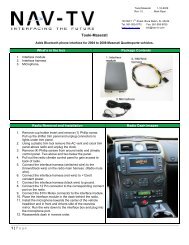
Dash Pictures 2010 up<br />
SPORT/LR4<br />
1
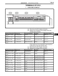
Both the video and rear<br />
view <strong>camera</strong> inputs are<br />
located on the grey 6 pin<br />
plug at the back of the<br />
LCD monitor. Some vehicles<br />
are prewired and some are<br />
<strong>not</strong>. The provided RCA cables<br />
will either need to be soldered<br />
onto ex<strong>is</strong>ting wires or inserted<br />
into the empty slots<br />
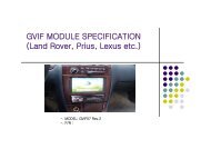
With the grey 6 pin connector<br />
locking tab facing upwards,<br />
the far right top and bottom<br />
slots are for the video input.<br />
The center top and bottom<br />
slots are the RVC video input.<br />
On both inputs the top <strong>is</strong> +<br />
and the bottom <strong>is</strong> negative.<br />
RVC+ ________<br />
RVC-<br />
_____<br />
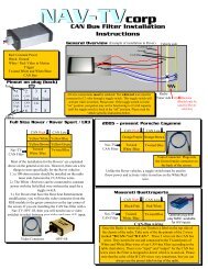
Optical Cable Connections<br />
Plug everything back in making sure that all optical leads are locked into place and that the<br />
locks themselves are in place.<br />
2
Installation instructions<br />
Full-Size Range Rover: The installation of both the optical audio module and the video in motion/<br />
<strong>camera</strong> module <strong>is</strong> performed at the tuner. The tuner <strong>is</strong> located on the passenger side of the vehicle<br />
behind and underneath the glove box. In every case, the LCD monitor must be accessed as well to<br />
populate the 6 pin grey connector with the RVC and Video inputs. Follow the instructions below for<br />
vehicles with and without a factory DVD player.<br />
1) Remove the passenger side running board and kick panel.<br />
2) Remove the T-20 torx screws from the black plastic shield below the glovebox (if you were a<br />
passenger sitting in the passenger seat your toes would be directly below th<strong>is</strong> panel) remove the<br />
panel and set aside.<br />
3) Locate the tuner box located near the firewall held in by two 8 MM bolts. The box will be silver in<br />
color and measures approximately 7” x 11” x 1”. Remove the two 8 MM bolts that secure the tuner<br />
box to allow access to the wiring harnesses.<br />
4) Unplug the power harness from the tuner and place the factory male connector into the supplied<br />
female connector on the NAV-<strong>TV</strong> T-harness. Place the aftermarket male connector back into the<br />
tuner. Insert the supplied 8 pin female molex to 18 pin male mini molex adapter into the 8 pin male<br />
molex plug on the T-harness and then plug the 18 pin male connector into the video in motion/<br />
<strong>camera</strong> module. NOTE: No wires on the 8 to 18 pin adapter harness will be used including the<br />
RCA ends. No connections will be made to ANY of these wires or RCA ends.<br />
5) Remove the factory MOST fiber optic cable from the tuner by pressing on the retaining clip and<br />
pulling away from the tuner. Using the diagram in page 2, install the supplied fiber optic cable<br />
into the loop wired in series to create two ends. Plug one end into the tuner and the other into the<br />
supplied MOST fiber optic audio module.<br />
6) Insert the 12 pin male connector from the T-harness into the MOST fiber optic audio module. Run<br />
the audio from your external A/V source to the unlabeled white and red audio input RCAs on the<br />
audio module ( RCA cables <strong>not</strong> supplied).<br />
VEHICLES WITHOUT A FACTORY DVD PLAYER: On full-sized Range Rovers the LCD monitor DOES<br />
NOT have to be removed. To access the back of the monitor use a soft pry tool to remove the vent<br />
above the LCD screen on the top of the dash. Once the vent <strong>is</strong> removed you can access the 6 pin grey<br />
plug at the back of the monitor. Follow the instructions on page two for the video input positions and<br />
either populate the empty plugs with the included RCAs or solder onto the ex<strong>is</strong>ting wires if the<br />
positions are already populated. Run a video RCA cable (<strong>not</strong> provided) from your rear view <strong>camera</strong> and<br />
aftermarket A/V source directly to the RCA inputs at the back of the monitor.<br />
VEHICLES WITH A FACTORY DVD PLAYER: Access the 6 pin grey plug as described above and<br />
insert the RVC RCA into the open slot or solder onto the ex<strong>is</strong>ting wires (referrence page 2 if needed).<br />
Run an RCA (<strong>not</strong> provided) from your RVC directly to th<strong>is</strong> RCA on the back of the monitor. On vehicles<br />
with a factory DVD player, the far right video input sections of the 6 pin grey plug will be populated.<br />
In th<strong>is</strong> case it <strong>is</strong> the direct video feed from the factory DVD player in the rear of the vehicle. The<br />
MOST optical module has a built-in switching network to allow the ex<strong>is</strong>tance of both a factory<br />
DVD player and an external aftermarket A/V source. About 3” back of the grey plug, cut the factory
video cable in half. Solder a female RCA (supplied) onto the video cable positive and negative going towards<br />
the 6 pin grey plug. Use the pin position diagram on page 2 for referrence. The supplied RCA cable will have<br />
two ends, a red or white and a black. The red or white <strong>is</strong> the positive lead and the black <strong>is</strong> the negative lead.<br />
If there are any questions you can use a multi-meter set on continuity and test for continuity between the center<br />
pin (+) of the RCA and one of the corresponding bare wires. Th<strong>is</strong> <strong>is</strong> also the case if the shield (-) must be<br />
Th<strong>is</strong> RCA will be your video input to the monitor. Run an RCA cable (<strong>not</strong> supplied) from the soldered RCA video<br />
onto the vehicle side of the factory video wire you cut 3” from the grey 6 pin plug. Run an RCA (<strong>not</strong> supplied)<br />
SPORT AND LR4:<br />
the tuner <strong>is</strong> located behind the factory radio and the LCD monitor must be accessed and removed during<br />
installation. NOTE: The radio does NOT have to be removed during th<strong>is</strong> installation, only the LCD screen.<br />
1) Remove the trim containing the PTS button that runs over the top of the radio by prying with a soft pry<br />
tool.<br />
2) Remove the torx T-20 screws from the bottom section of the left and right vents (surrounding the LCD screen)<br />
and remove them.<br />
3) Remove the torx screws that secure the LCD monitor, unplug the cables and set the LCD monitor aside.<br />
4) Remove the power harness from behind the radio by reaching into the cavity on top of the radio, applying<br />
pressure to to harness retainment clip, and remove the harness.<br />
5) Perform the optical connections at the LCD monitor location as described on pages 2 and 3 instead of at the<br />
tuner.<br />
6) Install the rest of the system as described in pages 3 and 4 under the Full-Sized instructions.<br />
FAQ<br />
1) After installation the system does <strong>not</strong> boot up properly.<br />
modules are plugged in.<br />
2) I get a black screen while in <strong>reverse</strong>.<br />
A) A black screen means that our module <strong>is</strong> working. The <strong>is</strong>sue <strong>is</strong> either in the RCA installation (backwards) or<br />
that there <strong>is</strong> a defective <strong>camera</strong>, RCA cable or the <strong>camera</strong> simply <strong>is</strong> <strong>not</strong> getting power.<br />
3) I installed th<strong>is</strong> on a vehicle with a factory DVD player and when I switch between the factory DVD player<br />
and aftermarket source I am getting the picture from one and the audio from a<strong>not</strong>her.<br />
4) How do I activate the external video input?<br />
A) On vehicle without a factory DVD player you will have a new icon on your source selector named <strong>TV</strong>. Simply<br />
press the <strong>TV</strong> icon to enable the external video source. On vehicle with a factory DVD player you will have a new<br />
icon labeled DVD/<strong>TV</strong>. By pressing the icon you will select between the factory DVD player with one press, and<br />
the external video source with the next press of the same icon.<br />
5) How do I engage VIM?<br />
A) VIM <strong>is</strong> automatic and does <strong>not</strong> require and action from the end user.