Single Deflection Track Selection - AWCI
Single Deflection Track Selection - AWCI
Single Deflection Track Selection - AWCI

Create successful ePaper yourself
Turn your PDF publications into a flip-book with our unique Google optimized e-Paper software.
By the Metal Stud Manufacturer’s Association<br />
<strong>Single</strong> <strong>Deflection</strong><br />
<strong>Track</strong> <strong>Selection</strong><br />
Editor’s Note: This article is the first in a series of<br />
industry technical notes on cold-formed steel construction.<br />
It was compiled by MSMA with assistance<br />
from the Association of the Wall and Ceiling<br />
Industries—International the Drywall Information<br />
Trust Fund and the Northwest Wall and Ceiling<br />
Bureau.<br />
Since the popular use of steel studs for<br />
framing full height walls, there has<br />
been a recognition that the top of the<br />
wall needs to allow for deflection of the<br />
floor or roof assembly above when subjected<br />
to an applied live load. The<br />
allowance for deflection is essential for<br />
interior non-load bearing applications.<br />
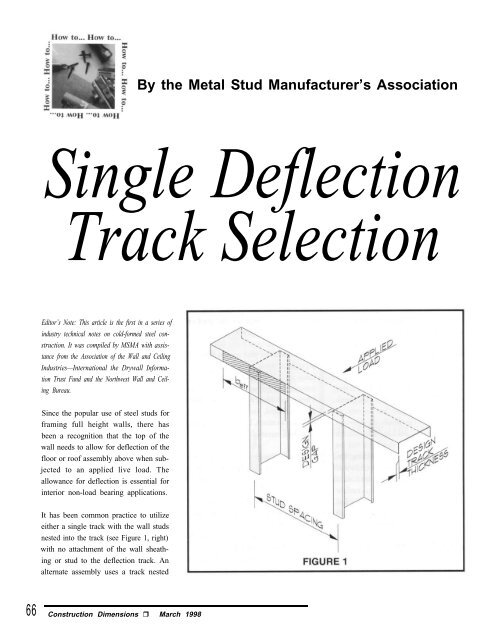
It has been common practice to utilize<br />
either a single track with the wall studs<br />
nested into the track (see Figure 1, right)<br />
with no attachment of the wall sheathing<br />
or stud to the deflection track. An<br />
alternate assembly uses a track nested<br />
66 Construction Dimensions r March 1998
into another track with no attachment<br />
of the nested inside track to the outside<br />
track The track within a track allows the<br />
stud at the top of the wall to be attached<br />
to the inside track to provide a more<br />
uniform load transfer to the outside<br />
deflection track flange and to stabilize<br />
the studs against rotation.<br />
Observations<br />
Over the years the question of how to<br />
determine the effective width of that<br />
portion of the track flange to be used<br />
for calculating the required design<br />
thickness of the leg for the single track<br />
deflection assembly was largely unanswered<br />
and was up to the design professional<br />
to determine.<br />
The design professional could assume<br />
an effective width equal to the width of<br />
the stud flange bearing against the side<br />
of the deflection track (conservative) or<br />
a width equal to the on-center spacing<br />
of the studs (un-conservative). The<br />
Army Corps of Engineers has adopted<br />
a procedure (ETL 1110-3-411) that<br />
recognizes the width of the stud flange<br />
plus a portion of the track flange on<br />
each side of the stud as being the effective<br />
width b eff (see Figure 1, page 66).<br />
It is recommended that the steel used<br />
for the deflection track have good ductility<br />
characteristics (tensile strength to<br />
yield point ratio not less than 1.08, and<br />
total elongation not less than 10 percent<br />
in a 2-inch gauge length). Good<br />
ductility characteristics reduces the<br />
possibility of micro cracking during the<br />
roll-forming process and provides<br />
inelastic reserve.<br />
Satisfactory performance is based on<br />
the following:<br />
n<br />
The track thickness must be suffi-
cient to resist plate bending along<br />
the effective track flange width,<br />
b eff .<br />
n<br />
Each stud flange must be stabilized<br />
to resist rotation of the stud.<br />
<strong>Deflection</strong> <strong>Track</strong><br />
Thickness<br />
Determination<br />
<strong>Deflection</strong> track thickness determination<br />
based on the Army Corps of<br />
Engineers ETL 1110-3-411 procedure<br />
utilizes the effective width of the<br />
track leg in plate bending. The equation<br />
for determining the required<br />
thickness is:<br />
where:<br />
t= required design thickness, in<br />
inches.<br />
P = the maximum reaction at the<br />
top of the stud, in pounds.<br />
e = gap between the track web and<br />
the point of application of the<br />
reaction P, in inches (design gap<br />
times 1.5).<br />
F Y = minimum steel yield stress, in<br />
psi.<br />
b eff = effective width of the track in<br />
plate bending, given by<br />
W stud = the stud flange width, in inches.<br />
Design curves can be developed utilizing<br />
a typical interior, non-load bearing<br />
stud flange width of 1.25", a yield<br />
stress of either 33 ksi or 50 ksi (50 ksi<br />
Official Publication of <strong>AWCI</strong> 71
is noted on the curves) and 16" and<br />
24" on center stud spacing. A series of<br />
such curves are given in Figures 2<br />
through 7 (pages 67-72).<br />
By knowing the non-load bearing wall<br />
height, you can determine the lateral<br />
design load (typically 5 psf for interior<br />
walls), the design gap (gap between the<br />
end of the stud and the track web), the<br />
stud spacing and the steel minimum<br />
yield stress of the track, the required<br />
design thickness of the single deflection<br />
track.<br />
As an example:<br />
Design load 5 = psf<br />
Stud spacing = 24" o.c.<br />
Design gap = 0.5"<br />
Minimum yield stress = 33 ksi<br />
Wall height = 15'-0"<br />
From Figure 3 design thickness of<br />
t = 0.0451" (18 ga.)<br />
Note: Maximum allowable wall height<br />
= 19.52 feet<br />
It is recommended that the depth of<br />
the deflection track flange be equal to<br />
the design gap plus 1 inch for one-story<br />
buildings and equal to two times the<br />
design gap plus 1 inch for all other<br />
applications to provide engagement of<br />
the stud into the deflection track The<br />
longer track leg, for multiple story<br />
buildings, allows for the floor system<br />
supporting the stud wall to deflect<br />
while still maintaining engagement of<br />
the stud in the deflection track.<br />
Note: The minimum uncoated delivered<br />
thickness can be equal to 95 percent<br />
of the design thickness per the<br />
1996 AISI “Specification for The<br />
Design of Cold-Formed Steel Structural<br />
Members,” Section A3.4.<br />
72 Construction Dimensions r March 1998