operating and safety manual - Academy Sports + Outdoors
operating and safety manual - Academy Sports + Outdoors
operating and safety manual - Academy Sports + Outdoors

Create successful ePaper yourself
Turn your PDF publications into a flip-book with our unique Google optimized e-Paper software.
“The Quality Goes In Before The Rifle Goes Out”<br />
<strong>operating</strong><br />
<strong>and</strong><br />
<strong>safety</strong><br />
<strong>manual</strong><br />
For<br />
AR15 Type<br />
Semi-Automac<br />
Models<br />
Windham Weaponry Part No: MAN-OP-AR<br />
Made in the U.S.A.
CAREFULLY READ THIS INSTRUCTION MANUAL PRIOR TO LOADING<br />
AND FIRING THIS FIREARM. FOLLOW ALL INSTRUCTIONS ON THE<br />
PROPER HANDLING AND SAFE USE OF THIS FIREARM!<br />
BEWARE OF DANGEROUS PROCEDURES<br />
WARNING! IF THIS FIREARM IS CARELESSLY OR IMPROPERLY<br />
HANDLED, UNINTENTIONAL DISCHARGE COULD RESULT AND COULD<br />
CAUSE INJURY, DEATH, OR DAMAGE TO PROPERTY.<br />
WARNING! THIS WEAPON COULD CHAMBER A ROUND IF IT IS<br />
DROPPED OR JARRED WITH A LOADED MAGAZINE IN PLACE AND<br />
WITH THE BOLT CARRIER ASSEMBLY LOCKED TO THE REAR.<br />
WARNING! BE SURE CAM PIN IS INSTALLED IN THE BOLT GROUP. IF<br />
IT ISN’T, THE RIFLE CAN STILL FIRE AND WILL EXPLODE!<br />
WARNING! IF THERE IS WATER IN THE BARREL, DO NOT FIRE THE<br />
RIFLE. IT COULD EXPLODE!<br />
CAUTION! USE ONLY CLEAN, DRY, HIGH QUALITY COMMERCIALLY<br />
MANUFACTURED AMMUNITION WHICH IS APPROPRIATE TO THE<br />
5.56MM NATO / .223 REM. CALIBER OF YOUR FIREARM. WINDHAM<br />
WEAPONRY DOES NOT RECOMMEND THE USE OF REMANUFAC-<br />
TURED OR HAND LOADED AMMUNITION BECAUSE IT MAY DAMAGE<br />
YOUR RIFLE.<br />
CAUTION! IF THE RIFLE STOPS FIRING (A MISFIRE) WITH A LIVE<br />
ROUND IN THE CHAMBER OF A HOT BARREL, REMOVE THE ROUND<br />
FAST! HOWEVER, IF YOU CANNOT REMOVE IT WITHIN 10 SECONDS,<br />
REMOVE MAGAZINE AND WAIT 15 MINUTES WITH THE RIFLE POINT-<br />
ING IN A SAFE DIRECTION SO YOU WON’T BE HURT BY A POSSIBLE<br />
ROUND “COOKING-OFF” (I.E. THE ROUND DETONATING FROM THE<br />
HEAT OF THE BARREL). ALWAYS KEEP YOUR FACE AWAY FROM THE<br />
EJECTION PORT WHILE CLEARING A HOT CHAMBER.<br />
CAUTION! IF RIFLE’S BOLT FAILS TO UNLOCK, AND YOU TRY TO FREE IT<br />
BY TAPPING THE BUTTSTOCK ON THE GROUND WHILE PULLING ON<br />
THE CHARGING HANDLE, KEEP YOURSELF CLEAR OF THE MUZZLE!<br />
PLACE THE SAFETY SELECTOR LEVER ON SAFE.<br />
CAUTION! IF YOU HEAR A NOTICEABLE DIFFERENCE IN SOUND OR<br />
RECOIL DURING FIRING, STOP FIRING! EITHER CONDITION COULD<br />
INDICATE AN INCOMPLETE POWDER BURN AND/OR A BULLET STUCK<br />
IN THE BORE.
This <strong>manual</strong> is based upon the<br />
U.S. Gov’t. Issue Manual for M16<br />
A2 Rifles, <strong>and</strong> will be included with<br />
all semi-automac Windham<br />
Weaponry Firearms.<br />
Windham Weaponry is steadfast<br />
in its goal to produce the finest<br />
AR15 type rifle <strong>and</strong> carbine<br />
possible, <strong>and</strong> we encourage our<br />
customers to follow further developments<br />
on our website.<br />
www.windhamweaponry.com<br />
In the meanme, we encourage<br />
you to shoot safely, to enjoy the<br />
great outdoors, <strong>and</strong> to provide us<br />
feedback in our quest to produce<br />
the finest rifles in the world.<br />
Thanks, from your<br />
Windham Weaponry Team<br />
YOUR WARRANTY<br />
Your Transferable Lifeme<br />
Warrany is printed in full on the<br />
back cover of this <strong>manual</strong>. As soon<br />
as possible upon receipt of your<br />
Windham Weaponry firearm, go<br />
online, or call, to acvate your<br />
warranty. See:<br />
www.windhamweaponry.com<br />
or call Toll-Free: 855-808 1888<br />
Follow the Instrucons on the<br />
website warranty page. Your<br />
firearm’s warranty will be in effect<br />
upon compleon of these steps.<br />
The Windham Weaponry Team<br />
thanks you for your purchase of<br />
this fine rifle, <strong>and</strong> we hope you will<br />
enjoy it safely for many years. If<br />
you need parts, service or advice<br />
concerning your rifle, we are never<br />
more than a phone call away, <strong>and</strong><br />
will be pleased to help you.<br />
CAREFULLY READ THIS INSTRUCTION MANUAL<br />
PRIOR TO LOADING AND FIRING THIS FIREARM.<br />
FOLLOW ALL INSTRUCTIONS ON THE PROPER<br />
HANDLING AND SAFE USE OF THIS FIREARM!<br />
TABLE OF CONTENTS<br />
About Your Windham Weaponry Rifle 2<br />
Rifle Features & Controls - Locaon 2<br />
Familiarize Yourself With Your Rifle 3<br />
Range Safety Checks - Before You Fire! 6<br />
Loading A Magazine 6<br />
Preparing To Fire 7<br />
Chambering A Round From An Open Bolt 7<br />
Chambering A Round From A Closed Bolt 8<br />
Firing The Rifle 8<br />
If The Rifle Stops Firing - Immediate Acons 9<br />
If The Rifle Stops Firing - Remedial Acons 9<br />
Underst<strong>and</strong>ing Your Sight Adjustments 10<br />
The Dual Aperture Rear Sight 11<br />
25 Meter Zeroing Procedures 11<br />
Rifle Disassembly, Cleaning & Maintenance 13<br />
A Visual Guide To The WW-15 Rifle 16<br />
Cleaning Bolt, Bolt Carrier & Components 18<br />
Inspecon, Cleaning & Lubricaon 22<br />
Cleaning The Bore 22<br />
Magazine Disassembly & Cleaning 27<br />
Troubleshoong Problems / Soluons 28<br />
Shipping Rifles For Service 31<br />
Maintence Log / Zeroing-In Records / Notes 32<br />
Pg. 1
ABOUT YOUR WINDHAM WEAPONRY RIFLE<br />
• This operang <strong>manual</strong> covers Windham Weaponry models chambered for .223 Rem. /<br />
5.56mm NATO ammunion. They are lightweight, gas operated, air-cooled, magazine<br />
fed rifles that operate in semi-automac mode. This means that each me the trigger<br />
is pulled, a single round will fire unl the magazine is empty.<br />
• On all models, the upper <strong>and</strong> lower receivers are easily opened for cleaning <strong>and</strong><br />
inspecon. Upper <strong>and</strong> lower receivers are machined from forged 7075 T6 aircra<br />
aluminum.<br />
• Most Windham Weaponry models feature fully adjustable rear sights <strong>and</strong> elevaon<br />
adjustable front sights. Some models are designed to allow the owner to add their<br />
own choice of front <strong>and</strong> rear sights (e.g. Windham Weaponry SRC & Varmint<br />
Exterminator models).<br />
• Barrels on Windham Weaponry models are chrome lined 4150 chrome moly vanadium<br />
11595E steel or 416R grade stainless steel. They are 100% air gauged, bore scoped,<br />
head spaced <strong>and</strong> buon rifled - right h<strong>and</strong> twist with 6 l<strong>and</strong>s <strong>and</strong> grooves. Refer to<br />
barrel markings for twist rate <strong>and</strong> caliber.<br />
• Windham Weaponry models are supplied with 6 posion telescoping bustocks or<br />
fixed style bustocks.<br />
• Most forends are ribbed <strong>and</strong> vented to allow heat dissipaon. Carbines feature M4<br />
double heat shield design forends.<br />
• All models feature vercal pistol grips <strong>and</strong> detachable magazines. St<strong>and</strong>ard magazine<br />
capacity is 30 rounds (depending on State regulaons), but all AR-15/M-16 type<br />
magazines of capacies from 5 to 40 rounds as well as c-drum magazines will fit <strong>and</strong><br />
funcon in Windham Weaponry models.<br />
RIFLE FEATURES & CONTROLS<br />
6 Posion<br />
Telestock<br />
Dual Aperture Rear Sight<br />
Rear Sight Elevaon Wheel<br />
Charging<br />
H<strong>and</strong>le<br />
Rear Sight Windage Knob<br />
A4 Removable Carry H<strong>and</strong>le<br />
Spent Brass Deflector<br />
Ejecon Port Cover<br />
A2 Front Sight Assembly<br />
A2 Flash Hider<br />
M4 Profile Barrel<br />
Magazine Release<br />
Buon<br />
M4 Double Heat Shield H<strong>and</strong>guards<br />
Telestock Latch<br />
Forward Assist Knob<br />
Pistol Grip<br />
Trigger<br />
Receiver<br />
Safety<br />
Indicator<br />
30 Rd. Magazine<br />
A4 Removable Carry H<strong>and</strong>le<br />
Carry H<strong>and</strong>le Locking Knobs<br />
Flat Top Upper Receiver<br />
Charging H<strong>and</strong>le<br />
6 Posion Telestock<br />
Bayonet Lug<br />
Front Sling Swivel<br />
Pivot Pin<br />
Bolt Catch<br />
Magazine<br />
Catch<br />
Takedown<br />
Pin<br />
Rear Sling Loop<br />
Pg. 2<br />
Safety Selector Lever
ALWAYS FOLLOW THE RULES OF SAFE GUN HANDLING!<br />
FAMILIARIZE YOURSELF WITH YOUR NEW WINDHAM WEAPONRY RIFLE.<br />
THEN FOLLOW THESE STEPS TO PREPARE TO USE THE RIFLE.<br />
ALWAYS ASSUME THE GUN YOU ARE HANDLING IS LOADED.<br />
POINT THE RIFLE IN A SAFE DIRECTION!<br />
Place <strong>safety</strong> selector lever on SAFE. NOTE: If the rifle is not<br />
cocked, the <strong>safety</strong> selector lever cannot be pointed toward<br />
SAFE.<br />
1. To lock bolt open, pull charging<br />
h<strong>and</strong>le rearward (A - Fig. 2). Press<br />
boom of bolt catch <strong>and</strong> allow bolt to<br />
move forward unl it engages bolt catch<br />
(B - Fig. 2). Return charging h<strong>and</strong>le to its<br />
forward posion.<br />
Note: Safety markings enhanced<br />
in photo for indenficaon.<br />
A<br />
Fig. 1<br />
If you haven’t done so before, now<br />
place <strong>safety</strong> selector lever on SAFE (as<br />
shown in Fig.1)<br />
B<br />
Fig. 2<br />
2. Remove chamber plug/tool (Fig. 3).<br />
Fig. 3<br />
Note: The chamber plug/tool should<br />
remain in the chamber when the rifle is not<br />
in use, or in storage.<br />
Look into the upper receiver <strong>and</strong> firing<br />
chamber to ensure there is no ammunion in<br />
the rifle (Fig. 4).<br />
Note: Be sure a magazine is not inserted in<br />
the rifle.<br />
3. Once you are sure the firing chamber is<br />
empty, <strong>and</strong> the <strong>safety</strong> selector lever is on<br />
SAFE, you can press the upper poron of the<br />
bolt catch, or pull the charging h<strong>and</strong>le all the<br />
way to the rear <strong>and</strong> release to allow the bolt<br />
to move forward.<br />
Fig. 4<br />
THE RIFLE IS NOW “CLEAR”.<br />
Pg. 3
4. Using your chamber plug/tool (or a<br />
punch) push the takedown pin in as far as it<br />
will go. Then pull on the head of the pin (from<br />
the right side of the rifle) unl it stops (Fig. 5).<br />
Fig. 5<br />
5. Push the front pivot pin in as far as it will<br />
go (Fig. 6) - then separate the upper <strong>and</strong> lower<br />
receivers (Fig. 7).<br />
Fig. 6<br />
Fig. 7<br />
6. Pull the charging h<strong>and</strong>le back unl<br />
it stops. The bolt carrier assembly will<br />
come out with it (Fig. 8).<br />
Li the bolt carrier back <strong>and</strong> up unl<br />
it is clear of the upper receiver.<br />
NOTE: Observe how the carrier key<br />
fits within the slot in the boom of the<br />
charging h<strong>and</strong>le.<br />
Fig. 8<br />
7. To remove the charging h<strong>and</strong>le,<br />
pull it to the rear unl it stops. Then li<br />
the charging h<strong>and</strong>le up, allowing the<br />
side tabs to clear the cutouts in the<br />
upper receiver (Fig. 9).<br />
Fig. 9<br />
Side tabs on<br />
charging h<strong>and</strong>le<br />
must clear the cutouts<br />
in the upper receiver for<br />
removal <strong>and</strong> reinseron.<br />
Pg. 4
8. Run a cleaning patch with oil through the barrel. Always pull<br />
your cleaning rod from chamber to muzzle (Fig. 10).<br />
Fig. 10<br />
9. Run a dry patch through the barrel (again, always from chamber<br />
to muzzle).<br />
10. Visually inspect the barrel to make sure it is free of any debris<br />
or obstrucons.<br />
11. To reassemble your rifle, follow the preceding steps (1 thru 7)<br />
in reverse order.<br />
NOTE: When installing the<br />
charging h<strong>and</strong>le, remember that the<br />
tabs on the side of the h<strong>and</strong>le need<br />
to drop into corresponding cutouts<br />
in the channel within the upper<br />
receiver (Fig. 11).<br />
Fig. 11<br />
Tabs<br />
NOTE: When installing the bolt<br />
carrier assembly, the bolt must be<br />
pulled all the way forward before<br />
being inserted in the upper receiver<br />
(Fig. 12).<br />
The bolt carrier can then be<br />
reinserted in the upper receiver. the<br />
gas key must fit into the channel in<br />
the charging h<strong>and</strong>le. then, both<br />
charging h<strong>and</strong>le <strong>and</strong> carrier can slide<br />
into receiver (Fig. 13).<br />
Fig. 12<br />
With the upper receiver<br />
reassembled, it can then be joined<br />
to the lower receiver.<br />
NOTE: When pivong the rifle<br />
closed, the hammer should be in the<br />
cocked (down) posion (Fig. 14). The<br />
<strong>safety</strong> can then be moved to the<br />
SAFE posion.<br />
12. Pull the charging h<strong>and</strong>le to the<br />
rear <strong>and</strong> insert the chamber<br />
plug/tool into the chamber. Then<br />
ease the charging h<strong>and</strong>le <strong>and</strong> bolt<br />
carrier forward, <strong>and</strong> latch the<br />
charging h<strong>and</strong>le in place.<br />
YOUR RIFLE IS NOW READY<br />
TO TAKE TO THE RANGE.<br />
Hammer<br />
Pg. 5<br />
Safety<br />
Fig. 13<br />
Fig. 14<br />
Pg. 5
RANGE SAFETY CHECKS - BEFORE YOU FIRE!<br />
SAFETY SELECTOR FUNCTION CHECK: Perform this <strong>safety</strong> funcon check to ensure that the<br />
<strong>safety</strong> selector lever works properly.<br />
ALWAYS ASSUME THE RIFLE YOU ARE HANDLING IS LOADED, AND POINT IT IN A SAFE<br />
DIRECTION! WHEN PERFORMING THIS SAFETY CHECK, MAKE SURE THERE IS NO MAGAZINE<br />
IN THE RIFLE.<br />
1. Pull charging h<strong>and</strong>le to the rear, remove chamber plug, <strong>and</strong> release charging h<strong>and</strong>le. Place<br />
selector lever on SAFE. Pull trigger. HAMMER SHOULD NOT FALL.<br />
2. Place selector lever in FIRE posion, point rifle in a safe direcon, <strong>and</strong> pull trigger.<br />
HAMMER SHOULD FALL.<br />
3. Hold trigger to the rear, pull charging h<strong>and</strong>le to the rear <strong>and</strong> release charging h<strong>and</strong>le. Then<br />
release pressure on the trigger with a slow, smooth moon, without hesitaons or stops, unl<br />
the trigger is fully forward. YOU SHOULD HEAR A CLICK AND THE HAMMER SHOULD NOT FALL.<br />
4. Repeat the FIRE posion test FIVE TIMES (Step 2 above). The rifle must not malfuncon<br />
during any of these five tests.<br />
WARNING: IF THE RIFLE MALFUNCTIONS DURING ANY OF THESE FIVE TESTS,<br />
CONTACT THE FACTORY FOR TECHNICAL SUPPORT. Call Toll Free: 1-855-808-1888<br />
LOADING A MAGAZINE<br />
1. Use only quality 5.56mm NATO or .223 Rem. caliber ammunion! Brass cased ammunion<br />
is recommended.<br />
CAUTION! DO NOT USE AMMUNITION THAT IS DENTED, SCRATCHED, CORRODED,<br />
OR DAMAGED.<br />
2. Insert a cartridge between the feed lips of the magazine with the bullet p forward. Push<br />
the cartridge down unl it is held by the magazine feed lips (as shown Arrow A - Fig. 15).<br />
3. Then slide the cartridge backward to seat it against the inside back of the magazine (Arrow<br />
B - Fig. 15). Place the next cartridge on top of the previous one <strong>and</strong> repeat steps 2 & 3 unl<br />
desired number of cartridges are loaded into the magazine (Fig. 16).<br />
CAUTION! DO NOT LOAD LIVE AMMUNITION INTO YOUR MAGAZINE UNTIL YOU<br />
ARE READY TO SHOOT.<br />
NOTE: AR15 / M16 magazines are manufactured to hold various capacies of<br />
ammunion - anywhere from 5 to 100 cartridges - but all funcon in the same manner. Do not<br />
try to force more cartridges into a magazine than it was designed to hold.<br />
Feed<br />
Lips<br />
B<br />
A<br />
Magazine<br />
Follower<br />
Fig. 15 Fig. 16<br />
Pg. 6
PREPARING TO FIRE<br />
ALWAYS PRACTICE SAFE FIREARMS HANDLING! ASSUME THE RIFLE YOU ARE<br />
HANDLING IS LOADED!<br />
ALWAYS USE EYE AND EAR PROTECTION FOR SAFETY WHEN SHOOTING!<br />
Pull charging h<strong>and</strong>le to the rear <strong>and</strong><br />
lock bolt carrier back by depressing the<br />
boom of the bolt catch. Slide the<br />
charging h<strong>and</strong>le forward unl it latches<br />
onto the upper receiver. Move the <strong>safety</strong><br />
selector to the SAFE posion (Fig. 17).<br />
Fig. 17<br />
Push a magazine up into the magazine<br />
well unl the magazine catch engages<br />
<strong>and</strong> holds the magazine in place (Fig. 18).<br />
INSERTING A MAGAZINE<br />
Fig. 18<br />
CHAMBERING A ROUND FROM AN OPEN BOLT<br />
With a magazine inserted, press upper poron of the bolt catch (Fig. 19). Bolt should spring<br />
forward - chambering a round. Or, you can pull back on the charging h<strong>and</strong>le <strong>and</strong> release.<br />
Then tap the forward assist to ensure bolt is fully forward <strong>and</strong> locked (Fig. 20).<br />
Fig. 19 Fig. 20<br />
Pg. 6 Pg. 7
CHAMBERING A ROUND FROM A CLOSED BOLT<br />
KEEP YOUR FINGER OFF THE TRIGGER UNTIL YOU ARE READY TO FIRE THE<br />
RIFLE.<br />
Insert a loaded magazine into the magazine well unl the magazine catch engages <strong>and</strong> holds<br />
the magazine. Slap up on the boom of the magazine to ensure it is seated correctly.<br />
Pull charging h<strong>and</strong>le fully to the rear (Fig. 21).<br />
Release charging h<strong>and</strong>le. Never “ride” the charging h<strong>and</strong>le forward. The charging h<strong>and</strong>le <strong>and</strong><br />
bolt assembly should slide forward from the pressure of the acon spring to chamber a round<br />
(Fig. 22).<br />
Then tap the forward assist to ensure bolt is fully forward <strong>and</strong> locked (Fig. 23). Now move the<br />
<strong>safety</strong> selector to the SAFE posion.<br />
Fig. 21 Fig. 22 Fig.23<br />
FIRING THE RIFLE<br />
The rifle is now loaded, a round is chambered, the <strong>safety</strong> selector lever should be in<br />
the safe posion.<br />
CAUTION! ALWAYS POINT THE MUZZLE IN A SAFE DIRECTION!<br />
To fire the rifle:<br />
1. Aim at your target.<br />
2. Move <strong>safety</strong> selector lever from SAFE to FIRE (Fig. 24).<br />
3. Squeeze the trigger – release trigger pressure.<br />
4. The rifle will eject the spent cartridge <strong>and</strong> chamber another in<br />
preparaon for the next shot. This is called firing in “semi-automac<br />
mode”. One round will be fired with each pull of the trigger, <strong>and</strong> the<br />
Fig. 24<br />
rifle will automacally reload, unl the magazine is empty.<br />
NOTE: Aer the last round is fired, the bolt carrier will lock in the rear posion. You can then<br />
push the magazine release buon to drop out the empty magazine*, insert a fresh magazine,<br />
release the bolt catch, <strong>and</strong> a new round will automacally be chambered in preparaon for the<br />
next shot.<br />
If you stop firing the rifle before the magazine is empty:<br />
1. Move <strong>safety</strong> to SAFE posion.<br />
2. Remove magazine.<br />
3. Lock bolt to the rear (to remove live round from the chamber).<br />
4. Visually inspect the chamber to ensure that it is empty.<br />
*For California approved models, use the chamber plug/tool to<br />
depress the bullet buon to drop out the empty magazine (Fig. 25).<br />
Pg. 8<br />
Fig. 25
IF THE RIFLE STOPS FIRING - IMMEDIATE ACTIONS<br />
IF THE RIFLE FAILS TO FIRE WHEN THE TRIGGER IS SQUEEZED...<br />
1. Keep the rifle safely pointed downrange for 30 seconds.<br />
2. Remove the magazine.<br />
3. Lock the bolt to the rear (take note if a live round is ejected).<br />
4. Place <strong>safety</strong> selector in safe posion.<br />
5. Visually inspect the chamber to ensure that the chamber is empty!<br />
A. If a live round was ejected when clearing the rifle, inspect the round for evidence of<br />
possible ammo failure.<br />
B. If a live round was not ejected, reinsert the magazine in the magazine well unl the<br />
magazine catch engages <strong>and</strong> holds the magazine securely in place. Press bolt catch to chamber a<br />
round <strong>and</strong> resume firing.<br />
IF YOU HEAR A NOTICEABLE DIFFERENCE IN SOUND OR RECOIL DURING<br />
FIRING, STOP FIRING! EITHER CONDITION COULD INDICATE AN<br />
INCOMPLETE POWDER BURN AND/OR A STUCK BULLET IN THE BORE.*<br />
1. Remove the magazine.<br />
2. Lock the bolt to the rear.<br />
3. Place <strong>safety</strong> selector in safe posion <strong>and</strong> visually check that the chamber is empty.<br />
4. Visually inspect the bore or insert a cleaning rod in the bore to ensure there is not a bullet<br />
stuck in the bore.<br />
*If a bullet is stuck in the barrel, do not aempt to remove it. Contact Windham Weaponry<br />
for Technical Support. Call: 1-855-808-1888<br />
IF THE RIFLE STOPS FIRING - REMEDIAL ACTIONS<br />
WARNING! If your rifle stops firing with a live round in the chamber of a hot barrel,<br />
remove the round FAST! However, if you cannot remove it within 10 seconds, remove<br />
the magazine <strong>and</strong> wait 15 minutes with the rifle poinng in a safe direcon! This way<br />
you won’t get hurt by a possible round “cooking off” (meaning a round may detonate<br />
unexpectedly from being exposed to the heat of the rifle’s firing chamber). Always be sure to<br />
keep your face away from the ejecon port while clearing a hot chamber.<br />
If your rifle sll fails to fire, check the troubleshoong secon of this <strong>manual</strong>.<br />
Pg. 9
UNDERSTANDING YOUR SIGHT ADJUSTMENTS<br />
THE FRONT SIGHT IS ADJUSTABLE FOR ELEVATION<br />
FRONT SIGHT ADJUSTMENT: To adjust<br />
elevaon, depress detent <strong>and</strong> rotate post using a<br />
firing pin, punch or the specifically designed front<br />
sight adjustment tool. To raise strike of bullet,<br />
rotate post in the direcon of arrow marked up<br />
(clockwise) (Fig. 26).<br />
Reverse the direcon of rotaon to lower strike<br />
of bullet. Each of the 4 graduaons (notches)<br />
moves the point of impact of bullet as indicated<br />
below.<br />
Elevaon adjustments at front sight post (A2<br />
four posion) - one “click” equals:<br />
Front Sight Detent<br />
Fig. 26<br />
For Carbine Sight Radius*:<br />
DISTANCE IMPACT<br />
25 meters 1.2 cm (1/2”)<br />
100 meters 4.8 cm (1 7/8”)<br />
200 meters 9.6 cm (3 3/4”)<br />
300 meters 14.4 cm (5 3/4”)<br />
For Rifle Sight Radius*:<br />
DISTANCE IMPACT<br />
25 meters 0.83 cm (3/8”)<br />
100 meters 3.5 cm (1 3/8”)<br />
200 meters 6.5 cm (2 5/8”)<br />
300 meters 10.0 cm (4”)<br />
Sighng Data from Army Marksmanship <strong>manual</strong>.<br />
25 meters = 27 yards + 1 . (82 .) 100 meters = 109 yards + 1 . (328 .)<br />
THE REAR SIGHT IS ADJUSTABLE FOR WINDAGE AND ELEVATION<br />
Turning the windage knob clockwise will move<br />
bullet impact to the right. Turning the windage<br />
knob counter-clockwise will move bullet impact<br />
to the le (Fig. 27).<br />
Once the rifle is zeroed, the rear sight is<br />
adjustable for elevaon when firing at distances<br />
of 300 - 600 meters (A4 sights) or 300 - 800<br />
meters (A2 sights).<br />
Windage adjustments - one “click” equals:<br />
Fig. 27<br />
Windage Knob<br />
Pg. 10<br />
For Carbine Sight Radius*:<br />
DISTANCE IMPACT<br />
25 meters 0.5 cm (1/4”)<br />
100 meters 2.75 cm (1”)<br />
200 meters 5.5 cm (2 1/4”)<br />
300 meters 8.5 cm (3 1/4”)<br />
*AII the above values have been rounded off. To<br />
remember your correct zero windage, note<br />
locaon of windage scale <strong>and</strong> windage knob<br />
pointer (heavy mark on outside of knob). Once<br />
you have established your correct zero windage<br />
leave your windage scale <strong>and</strong> windage knob<br />
pointer on these sengs at all mes.<br />
For Rifle Sight Radius*:<br />
DISTANCE IMPACT<br />
25 meters 0.33 cm (1/8”)<br />
100 meters 1.5 cm (1/2”)<br />
200 meters 2.5 cm (1”)<br />
300 meters 4.0 cm (1 1/2”)<br />
Windage<br />
Scale<br />
Windage<br />
Knob<br />
Pointer
THE DUAL APERTURE REAR SIGHT<br />
ADJUSTABLE FOR ELEVATION & WINDAGE<br />
SHORT RANGE - The “02” (larger) aperture is<br />
used for 0-200 meters range. As shown below,<br />
the sight is set for 0 - 200 meters. This larger<br />
aperture is only used when the rear sight is all<br />
the way down. In other words, the 300-meter<br />
mark is aligned with the mark on the le side<br />
of the receiver (Fig. 28).<br />
A2 sights -<br />
A4 sights -<br />
NORMAL RANGE - The aperture is<br />
unmarked <strong>and</strong> used for most firing situaons.<br />
It is used in conjuncon with the elevaon<br />
knob for 300, 400, 500, 600, 700, <strong>and</strong> 800<br />
meter targets with A2 sights (Fig. 29).<br />
With A4 carry h<strong>and</strong>le sights, ranges are<br />
300, 400, 500, 600 meters.<br />
1 min. elevaon<br />
1/2 min. windage<br />
1/2 min. elevaon<br />
1/2 min. windage<br />
A2 elevaon wheels<br />
are marked 8/3<br />
A4 elevaon wheels<br />
are marked 6/3<br />
Fig. 28 Fig. 29<br />
Short Range (0-200 meters)<br />
Normal Range - A2 Sights: 300-800 meters<br />
A4 Sights: 300-600 meters<br />
25 METER ZEROING PROCEDURES<br />
By following the steps below <strong>and</strong> establishing a zero at 25 meters, your rifle sights will be set<br />
with a 300-meter balesight.<br />
1. Do not move front sight post at this me. It was set at the factory <strong>and</strong> should be very close<br />
to your zero.<br />
2. Center the rear sight aperture by turning the windage knob le or right (this is called<br />
mechanical zero windage.)<br />
3. The unmarked (smaller) aperture should be up.<br />
4. Rotate elevaon knob in the<br />
down direcon (counter-clockwise -<br />
Fig. 30<br />
Fig. 30). To boom out the rear sight,<br />
line up the 6/3 (A4 sights) or the 8/3<br />
(A2 sights) with the corresponding<br />
index mark above the elevaon<br />
wheel. This is called “mechanical zero<br />
elevaon” for the rear sight.<br />
5. Now rotate the elevaon knob up (clockwise) one click past the 300-meter mark for A2<br />
sights or 2 clicks for A4 sights. From this point on, the rear sight elevaon knob should not be<br />
moved. Any changes in elevaon required in the following zeroing steps are made to the front<br />
sight post only.<br />
6. Carefully aim <strong>and</strong> fire at the center of the target bulls-eye.<br />
7. If your shot group is not in the center of the bulls-eye, calculate the required “clicks”<br />
necessary to move your next shot group into the bulls-eye using the elevaon <strong>and</strong> windage<br />
values in the “Underst<strong>and</strong>ing Your Sight Adjustment” secon on the previous page. Remember<br />
that any changes in elevaon are made by moving the front sight post only.<br />
A. In order to raise your next shot group, rotate the front sight post clockwise. In order to<br />
lower your next shot group, rotate the front sight post counterclockwise.<br />
B. Changes in windage are made with the windage knob. To move the shot group to the le,<br />
turn the windage knob counterclockwise. To move the shot group to the right, turn the windage<br />
knob clockwise.<br />
Pg. 11
25 METER ZEROING PROCEDURES (connued)<br />
8. Carefully aim <strong>and</strong> fire another group at the center of the target bulls-eye.<br />
9. Repeat steps 7 <strong>and</strong> 8, if required.<br />
10. When your group is on target, your sight is now “calibrated” for balesight zero. To place<br />
your actual 300-meter zero on the rifle, rotate the elevaon knob down two clicks for A4 sights<br />
or one click for A2 sights. The range scale’s 300-meter mark should now be aligned with the<br />
corresponding index above the elevaon wheel.<br />
ONCE YOU<br />
ARE FINISHED<br />
AT THE RANGE...<br />
1. Clear the rifle to ensure the<br />
chamber is empty (Fig. 31).<br />
2. Place <strong>safety</strong> in the safe posion.<br />
3. Pull the charging h<strong>and</strong>le to the<br />
rear <strong>and</strong> insert the chamber plug/tool<br />
into the chamber. Then ease the<br />
charging h<strong>and</strong>le <strong>and</strong> bolt forward <strong>and</strong><br />
latch in place (Fig. 32).<br />
THE RIFLE IS NOW SAFE TO<br />
TRANSPORT FROM THE RANGE.<br />
Fig. 31<br />
Fig. 32<br />
Pg. 12
RIFLE DISASSEMBLY, CLEANING & MAINTENANCE<br />
ALWAYS FOLLOW THE RULES OF SAFE GUN HANDLING!<br />
ALWAYS ASSUME THE GUN YOU ARE HANDLING IS LOADED.<br />
POINT THE RIFLE IN A SAFE DIRECTION!<br />
Place the <strong>safety</strong> selector lever on SAFE (Fig.33).<br />
NOTE: If the rifle is not cocked, the <strong>safety</strong> selector lever<br />
cannot be pointed toward SAFE.<br />
1. To lock the bolt open, pull the charging h<strong>and</strong>le rearward<br />
(A - Fig. 34). Press the boom of the bolt catch <strong>and</strong> allow the<br />
bolt to move forward unl it engages the bolt catch (B - Fig. 34).<br />
Return the charging h<strong>and</strong>le to its forward posion.<br />
If you haven’t done so before, place the <strong>safety</strong> selector lever on SAFE.<br />
Fig. 33<br />
A<br />
Fig. 35<br />
B<br />
Fig. 34<br />
2. Remove the chamber plug/tool (Fig. 35).<br />
Look into the upper receiver <strong>and</strong> firing<br />
chamber to ensure there is no ammunion in<br />
the rifle (Fig. 36).<br />
NOTE: Be sure a magazine is not inserted in<br />
the rifle.<br />
Fig. 36<br />
3. Once you are sure the firing chamber is<br />
empty, <strong>and</strong> the <strong>safety</strong> selector lever is on<br />
SAFE, you can press the upper poron of the<br />
bolt catch, or pull the charging h<strong>and</strong>le all the<br />
way to the rear <strong>and</strong> release to allow the bolt<br />
to move forward (Fig 37).<br />
Fig. 37<br />
THE RIFLE IS NOW “CLEAR”.<br />
Pg. 13
RIFLE DISASSEMBLY, CLEANING & MAINTENANCE (Connued)<br />
4. Using your chamber plug/tool (or a<br />
punch) push the takedown pin in as far as it<br />
will go. Then pull on the head of the pin (from<br />
the right side of the rifle) unl it stops (Fig. 38).<br />
Fig. 38<br />
5. Push the pivot pin in as far as it will go<br />
(Fig. 39) - then separate the upper <strong>and</strong> lower<br />
receivers (Fig. 40).<br />
Fig. 39<br />
Fig. 40<br />
6. Pull the charging h<strong>and</strong>le back. The<br />
bolt carrier assembly will come out<br />
with it (Fig. 41).<br />
Li the bolt carrier back <strong>and</strong> up unl<br />
it is clear of the upper receiver.<br />
NOTE: Observe how the carrier key<br />
fits within the slot in the boom of the<br />
charging h<strong>and</strong>le (Fig. 42).<br />
Fig. 42<br />
Fig. 41<br />
Fig. 43<br />
7. To remove the charging h<strong>and</strong>le,<br />
pull it to the rear unl its side tabs clear<br />
the cutouts in the upper receiver (Fig.<br />
43).<br />
Side tabs on<br />
charging h<strong>and</strong>le<br />
must clear the cutouts<br />
in the upper receiver for<br />
removal <strong>and</strong> reinseron.<br />
Pg. 14
RIFLE DISASSEMBLY, CLEANING & MAINTENANCE (Connued)<br />
8. Remove the firing pin retaining pin (Fig.<br />
44) NOTE: Do not open or close the split<br />
end of the firing pin retaining pin, <strong>and</strong><br />
NEVER substute a common coer pin on<br />
reassembly.<br />
Fig. 44<br />
9. Push the bolt in to locked posion<br />
within the bolt carrier (Fig. 45).<br />
Fig. 45<br />
Fig. 46<br />
10. Drop the firing pin out of rear of the<br />
bolt carrier (Fig. 46).<br />
11. With the bolt pushed into the locked<br />
posion, remove the cam pin by rotang 1/4<br />
turn <strong>and</strong> liing out (Fig. 47).<br />
Fig. 47<br />
12. Remove the bolt assembly from the bolt<br />
carrier by pulling it straight out (Fig. 48).<br />
Fig. 48<br />
Pg. 15
RIFLE DISASSEMBLY, CLEANING & MAINTENANCE will connue on Page 18<br />
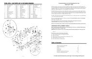
BUFFER SPRING P/N: 9390022<br />
TELESTOCK<br />
PLATE<br />
P/N: 9390021<br />
CARBINE BUFFER<br />
P/N: 1005-914-4578<br />
WELD SPRING<br />
P/N: 8448555<br />
DUAL HEATSHIELD HANDGUARDS<br />
P/N: DS4-HANDGUARD<br />
CARBINE GAS TUBE P/N: 1005-914-3504<br />
BARREL EXTENTION GAS TUBE SPRING PIN P/N: MS16562-106<br />
P/N: 9349054-W2BE<br />
BARREL NUT HANDGUARD CAP<br />
P/N: 9349054BBLN P/N: HCAP-RDHVYM4<br />
FRONT<br />
SIGHT<br />
BASE<br />
CRUSH WASHER<br />
FOR A2 FLASH A2 FLASH<br />
SUPPRESSOR SUPPRESSOR<br />
P/N: 12991533 P/N: 9349051<br />
M4 PROFILE CHROME LINED 16” BARREL<br />
4150 CHROME MOLY VANADIUM 11595E STEEL<br />
CHARGING<br />
HANDLE<br />
LATCH<br />
P/N: 8448519<br />
CHARGING HANDLE<br />
SPRING PIN<br />
P/N: 8448521<br />
CHARGING HANDLE SPRING<br />
P/N: 8448520<br />
CHARGING HANDLE ASSY.<br />
P/N: 8448517<br />
TELESTOCK KIT<br />
P/N: KIT-TELESTK<br />
FORWARD ASSIST<br />
SPRING PIN<br />
P/N: MS16562-121<br />
FORWARD ASSIST<br />
SPRING<br />
P/N: 8448540<br />
FORWARD ASSIST<br />
ASSY. ROUND<br />
P/N: 9349086<br />
TELESTOCK<br />
LOCKING RING<br />
P/N: 9390020<br />
BUFFER RETAINER<br />
P/N: 8448582<br />
BUFFER RETAINER<br />
SPRING<br />
P/N: 8448583<br />
BOLT CATCH PLUNGER<br />
SPRING P/N: 8448633<br />
SNAP RING<br />
P/N: MS16626-1137<br />
BOLT CATCH<br />
P/N: 8448628<br />
DELTA RING<br />
P/N: 8448712<br />
BOLT CATCH SPRING PIN<br />
P/N: MS16562-119<br />
BOLT CATCH<br />
PLUNGER<br />
P/N: 8448634<br />
EJECTION PORT COVER<br />
P/N: 8448525<br />
BARREL ASSEMBLY W. M4 CUTAWAY<br />
EJCT. PORT COVER SPRING<br />
P/N: 8448532<br />
EJCT. PORT<br />
COVER ROD C-CLIP<br />
P/N: MS16632-3012<br />
EJCT. PORT COVER ROD<br />
P/N: 8448533<br />
FRONT SIGHT TAPER PIN (2)<br />
P/N: 8448575<br />
SLING SWIVEL<br />
P/N: 8448571<br />
SLING SWIVEL RIVET<br />
P/N: 8448697<br />
FRONT SIGHT POST<br />
P/N: 9349056<br />
FRONT SIGHT POST DETENT<br />
P/N: 8448573<br />
FRONT SIGHT POST DETENT SPRING<br />
P/N: 8448574<br />
“The Quality Goes In<br />
Before The Rifle Goes Out”<br />
Made in<br />
The U.S.A.<br />
SAFETY SELECTOR AR<br />
P/N: 9381367-AR<br />
PISTOL GRIP WASHER<br />
P/N: MS35335-61<br />
PISTOL GRIP SCREW<br />
P/N: AN501D416-18<br />
SAFETY DETENT<br />
P/N: 8448631<br />
SAFETY DETENT SPRING<br />
P/N: 8448516<br />
TAKEDOWN PIN<br />
P/N: 8448584<br />
TAKEDOWN PIN TAKEDOWN<br />
DETENT SPRING PIN DETENT<br />
P/N: 8448586 P/N: 8448585<br />
DISCONNECTOR<br />
SPRING<br />
P/N: 8448594<br />
DISCONNECTOR AR<br />
P/N: 8448635-AR<br />
TRIGGER AR<br />
P/N: 8448592-AR<br />
ALUMINUM<br />
TRIGGER<br />
GUARD ASSY.<br />
P/N: 8448587<br />
TRIGGER<br />
GUARD<br />
SPRING PIN<br />
P/N: MS16562-129<br />
TRIGGER SPRING<br />
P/N: 8448593<br />
MAGAZINES<br />
30 / 20 / 10 / 5 ROUND<br />
HAMMER W. J PIN AR<br />
P/N: 9349110-AR<br />
HAMMER/TRIGGER PIN<br />
P/N: 8448609<br />
PIVOT PIN<br />
DETENT SPRING<br />
P/N: 8448586<br />
PIVOT PIN<br />
DETENT<br />
P/N: 8448585<br />
MAGAZINE CATCH<br />
P/N: 8448638<br />
MAGAZINE CATCH<br />
SPRING<br />
P/N: 8448637<br />
PIVOT PIN<br />
P/N: 8448621<br />
MAGAZINE CATCH BUTTON<br />
P/N: 8448636<br />
BOLT CARRIER<br />
WITH KEY<br />
P/N: 8448505<br />
GAS KEY SCREWS (2)<br />
P/N: 8448508<br />
For Parts Call Toll Free: 1-855-808-1888 - or Order Online: www.windhamweaponry.com<br />
Complete AR Rifles...<br />
<strong>and</strong> Everything to Keep Them Complete.<br />
a visual guide<br />
to the ww-15 rifle<br />
FIRING PIN<br />
RETAINING PIN<br />
P/N: 8448504<br />
BOLT CAM PIN<br />
P/N: 8448502<br />
BOLT CARRIER KEY<br />
BOLT<br />
P/N: 8448506<br />
GASRINGS (3)<br />
P/N: KIT-GASRINGS<br />
A4 CARRY HANDLE GROUP<br />
WITH 300-600 M REAR SIGHT<br />
P/N: 12951011<br />
EJECTOR SPRING<br />
P/N: 8448516<br />
EJECTOR CARTRIDGE<br />
P/N: 8448515<br />
EJECTOR SPRING PIN<br />
P/N: MS16562-98<br />
BOLT ASSY. COMPLETE<br />
P/N: 8448509<br />
HAMMER/TRIGGER PIN<br />
HAMMER SPRING<br />
EXTRACTOR SPRING INSERT<br />
P/N: 8448609<br />
P/N: 8448611 FIRING PIN-M16<br />
P/N: 8448755-INSERT<br />
EXTRACTOR CARTRIDGE<br />
P/N: 8448503<br />
P/N: 8448512<br />
EXTRACTOR SPRING<br />
PISTOL GRIP<br />
M16 BOLT CARRIER ASSEMBLY<br />
P/N: 8448755<br />
EXTRACTOR PIN<br />
P/N: 9349127<br />
P/N: 8448513<br />
P/N: 8448501<br />
EXTRACTOR “O”RING<br />
P/N: 8448755-ORING<br />
Pg. 16 © Windham Weaponry, Inc. 2012<br />
Pg. 17
RIFLE DISASSEMBLY, CLEANING & MAINTENANCE (Connued)<br />
CLEANING THE BOLT, BOLT CARRIER & COMPONENTS<br />
13. Once the bolt carrier has been disassembled...<br />
A. Clean the gas key on top of the bolt carrier with a pipe cleaner or Q-p (Fig. 49). Lightly oil<br />
the gas key (Fig. 50). Clean carbon <strong>and</strong> powder residue from vent holes <strong>and</strong> outer <strong>and</strong> inner<br />
surfaces of the bolt carrier. Use a bore brush - wet with CLP - to clean carbon <strong>and</strong> powder<br />
residue from around the gas tube.<br />
B. Clean <strong>and</strong> inspect the bolt, cam pin, firing pin <strong>and</strong> firing pin retaining pin thoroughly. Clean<br />
the bolt locking lugs, bolt rings, firing pin, firing pin hole <strong>and</strong> cam pin (Fig. 51).<br />
Fig. 49 Fig. 50<br />
Fig. 51<br />
14. Remove extractor pin by pushing it out with the p of the firing pin or a punch. Take care<br />
not to damage the firing pin, or lose the extractor pin (Fig. 52).<br />
15. Remove the extractor with its spring, insert <strong>and</strong> o-ring (Fig. 53).<br />
CAUTION: It is unlikely, but if the extractor spring should pop out of its recess, reset the<br />
spring by pressing it back in its recess with a punch as shown in Fig. 55 (on next page).<br />
Fig. 52 Fig. 53<br />
Pg. 18
RIFLE DISASSEMBLY, CLEANING & MAINTENANCE (Connued)<br />
CLEANING THE BOLT, BOLT CARRIER & COMPONENTS (connued)<br />
16. Check the extractor, extractor spring, insert <strong>and</strong> o-ring. If the extractor is chipped, or if the<br />
lip that engages the cartridge rim has broken edges, the extractor should be replaced. Check<br />
that the rubber insert is inside the extractor spring. Clean off any carbon buildup or powder<br />
residue (Fig. 54). Use CLP to clean any carbon buildup or powder residue in the extractor<br />
pocket/channel of the bolt. Use a pipe cleaner <strong>and</strong> CLP to clean the firing pin channel of carbon<br />
buildup <strong>and</strong> powder residue.<br />
NOTE: Extractor assembly has a rubber insert within the spring. Be sure not to lose it. If the<br />
spring comes loose, put the large end of spring in the extractor <strong>and</strong> seat it with a punch (Fig.55).<br />
Extractor Spring<br />
Rubber Insert<br />
O-ring<br />
Look for chips/broken edges<br />
Fig. 54<br />
Fig. 55<br />
17. Reinsert extractor in bolt (Fig. 56). Press extractor down to reinsert extractor pin (Fig. 57).<br />
Fig. 56<br />
Fig. 57<br />
LUBRICATING THE EJECTOR<br />
NOTE: Windham Weaponry does not recommend<br />
disassembly of the ejector for cleaning. You can ensure that<br />
your rifle ejects empty cases efficiently by following these<br />
lubricaon steps on a regular basis.<br />
17. With the bolt removed from the bolt carrier, hold it in<br />
your h<strong>and</strong> as shown with bolt face <strong>and</strong> ejector up. Lubricate<br />
the ejector with a few drops of CLP (Fig. 58).<br />
Fig. 58<br />
Pg. 19
RIFLE DISASSEMBLY, CLEANING & MAINTENANCE (Connued)<br />
LUBRICATING THE EJECTOR (connued):<br />
18. Place an empty .223 case, or a dummy<br />
round, under the lip of the extractor. With a<br />
rocking moon, press the case down against the<br />
ejector. The ejector is spring loaded, so you will<br />
feel some resistance. Press on the case unl it<br />
stops against the bolt face. Rock the case back<br />
<strong>and</strong> forth several mes to work the CLP<br />
lubricant into the ejector <strong>and</strong> its spring.<br />
Relubricate the ejector, <strong>and</strong> repeat the rocking<br />
moon several mes. Once the spring acon of<br />
the ejector is smooth <strong>and</strong> strong, dry off any<br />
excess lubricant (Fig. 59).<br />
INSPECTIONS BEFORE REASSEMBLY:<br />
Fig. 59<br />
CAUTION: The bolt should not have any cracks or fractures - especially in the cam pin hole<br />
area. The bolt face should not have any ping - especially around the firing pin hole. If this<br />
ping is found, the bolt must be replaced.<br />
• The cam pin should not be worn or cracked. If so, replace it.<br />
WARNING: If the cam pin is missing,<br />
DO NOT FIRE THE RIFLE - it will have a catastrophic failure!<br />
• The firing pin should not be worn, bent, or too blunt or too sharp.<br />
If the firing pin retaining pin is bent or worn, replace it. NEVER spread the legs of the firing pin<br />
retaining pin apart, <strong>and</strong> never use a common coer pin as a substute (Fig. 60).<br />
Fig. 60<br />
Ping?<br />
Cracks?<br />
Fractures?<br />
Worn?<br />
Bent?<br />
Too Blunt?<br />
Too Sharp?<br />
Wear?<br />
Cracks?<br />
Do not spread.<br />
LUBRICATION BEFORE REASSEMBLY:<br />
BOLT CARRIER GROUP: Apply a LIGHT COATING OF CLP to firing pin <strong>and</strong> firing pin recess<br />
(hole) in bolt, the extractor <strong>and</strong> its pin, <strong>and</strong> inner surfaces of the bolt carrier. GENEROUSLY<br />
LUBRICATE the outside areas of the bolt body <strong>and</strong> cam pin, <strong>and</strong> the slide <strong>and</strong> cam pin areas of<br />
the bolt carrier.<br />
STAGGER GAS RINGS: Gaps in<br />
the 3 gas rings should be evenly<br />
Fig. 61<br />
spaced around the bolt body<br />
(120° apart) to stop gas loss (Fig.<br />
61).<br />
Gas Ring Gap<br />
Pg. 20
RIFLE DISASSEMBLY, CLEANING & MAINTENANCE (Connued)<br />
NOW INSERT BOLT INTO CARRIER:<br />
Fig. 62<br />
WARNING: Regarding swapping bolts between rifles, while Windham Weaponry<br />
rifles <strong>and</strong> bolts are machined with great care, <strong>and</strong> are interchangeable with other<br />
Windham Weaponry bolts, we do not recommend exchanging bolts - parcularly<br />
those from other manufacturers, without first checking for proper headspacing with a<br />
Field Gauge or Go/No-Go Gauge for .223 Rem./5.56mm NATO.<br />
INSERT CAM PIN:<br />
Insert cam pin into carrier <strong>and</strong> hole<br />
in bolt body (Fig. 63).<br />
NOTE: The cam pin should only fit<br />
into the bolt from one side. If it<br />
doesn’t slip in easily, turn bolt body<br />
180° within the carrier <strong>and</strong> try again.<br />
Aer cam pin is inserted, turn it 90°.<br />
This allows for the inseron of the<br />
firing pin.<br />
INSERT FIRING PIN:<br />
Drop firing pin into back end of bolt<br />
carrier (Fig. 64) <strong>and</strong> seat by pushing in<br />
all the way (Fig. 65).<br />
INSERT FIRING PIN RETAINING PIN:<br />
Insert firing pin retaining pin into<br />
the firing pin retaining pin hole in the<br />
side of the carrier as shown (Fig.66).<br />
NOTE: In the cutaway drawing, the<br />
firing pin retaining pin sits behind the<br />
large shoulder of the firing pin. The<br />
test for correct posioning is that the<br />
firing pin should not fall out when bolt<br />
carrier group is turned upside down.<br />
Now that the bolt carrier is fully<br />
reassembled, move the bolt in <strong>and</strong> out<br />
of the carrier to ensure that the cam pin retains the<br />
bolt in the carrier <strong>and</strong> that the cam pin moves<br />
freely in the cam pin track.<br />
Tap the rear of the bolt carrier on a solid surface<br />
to ensure that the firing pin <strong>and</strong> its retaining is<br />
installed properly.<br />
Now lightly lubricate the bolt carrier assembly<br />
<strong>and</strong> charging h<strong>and</strong>le assembly.<br />
Fig. 64<br />
Fig. 63<br />
Fig. 65<br />
Fig. 66<br />
Pg. 21
INSPECTION, CLEANING & LUBRICATION OF YOUR RIFLE<br />
These steps have been adapted from the US Gov’t. Manual <strong>and</strong> involve<br />
the use of the st<strong>and</strong>ard issue M16 cleaning kit. You can achieve comparable<br />
results with any high quality rifle cleaning kit. Be sure your kit includes a<br />
quality cleaning rod; patch holder; coon flannel bore patches; pipe<br />
cleaners; a small toothbrush; brass wire bristle bore <strong>and</strong> chamber brushes;<br />
<strong>and</strong> a Cleaner/Lubricant/Preservave (CLP). If you use an ammonia based<br />
solvent while cleaning a chrome lined barrel, do not let it sit in the bore for<br />
more than 10 minutes. This will cause premature deterioraon of the<br />
chrome lining. The toothbrush is for cleaning parts <strong>and</strong> dislodging dirt. Pipe<br />
cleaners or Q-ps are for cleaning the gas key, gas tube <strong>and</strong> other hard to<br />
reach areas.<br />
CLEANING THE BORE:<br />
ALWAYS CLEAN FROM CHAMBER TOWARDS THE MUZZLE AND ALWAYS<br />
PULL THE BORE BRUSH THROUGH THE BORE<br />
The bore of your Windham Weaponry rifle has l<strong>and</strong>s <strong>and</strong> grooves called<br />
rifling. Rifling makes the bullet spin very fast as it moves down the bore <strong>and</strong><br />
down range. Because it twists so quickly, it is difficult to push a new, sff<br />
bore brush through the bore. You will find it much easier to pull your bore<br />
brush through the bore. Also, because the brush will clean beer if the<br />
bristles follow the grooves (called tracking), you want the bore brush to be<br />
allowed to turn as you pull it through.<br />
1. Swab out the bore with a patch moistened with CLP.<br />
2. If using a mul-piece military cleaning rod, aach three rod secons<br />
together but leave each one about two turns short of being ght (Fig. 67).<br />
3. Aach the bore brush. The rod <strong>and</strong> bore brush will twist as you pull it<br />
through - following the path of the rifling. NEVER reverse the direcon of<br />
the bore brush while it is in the bore.<br />
4. Point the muzzle down. Hold the upper receiver in one h<strong>and</strong> while<br />
inserng the end of the rod without the brush into the firing chamber. Let<br />
the rod fall straight through the bore. About 2-3 inches will be scking out<br />
of the muzzle at this point.<br />
5. Aach the h<strong>and</strong>le secon of the cleaning rod to the end of the rod<br />
scking out of the muzzle (Fig. 68).<br />
6. Pull the brush through the bore <strong>and</strong> out the muzzle.<br />
7. Aer one pull, take off the h<strong>and</strong>le secon <strong>and</strong> repeat the process.<br />
8. Send a patch through the bore once in a while to help clean out the<br />
crud that the brush is geng loose. You can use the same technique as<br />
described above to save me. Just replace the bore brush with the rod p<br />
(patch holder) <strong>and</strong> a wet patch. Drop it through. You won’t need to aach<br />
the h<strong>and</strong>le to pull only a patch through. If you leave the rods loose again,<br />
the patch will “track” in the rifling as before. Remember - always have the<br />
bore wet with cleaner before trying to pull a brush through.<br />
Bore<br />
Brush,<br />
or Patch<br />
&<br />
Three<br />
Rod<br />
Secons<br />
Drop<br />
Through<br />
Aach<br />
H<strong>and</strong>le<br />
- Pull<br />
Through<br />
Fig. 67<br />
Pg. 22<br />
Fig. 68
INSPECTION, CLEANING & LUBRICATION OF YOUR RIFLE (Connued)<br />
CLEANING THE UPPER RECEIVER<br />
1. Using CLP, clean all areas of the upper<br />
Fig. 69<br />
receiver (inside <strong>and</strong> out) to remove powder<br />
fouling, corrosion <strong>and</strong> dirt.<br />
NOTE: Never use a wire brush or any type of<br />
abrasive to clean the aluminum upper receiver<br />
- you could scratch <strong>and</strong> damage the anodized<br />
finish. A toothbrush can be effecve to loosen<br />
dirt buildup, <strong>and</strong> won’t scratch the receiver.<br />
2. Clean the chamber by moistening the<br />
larger chamber brush with CLP, <strong>and</strong> use plunge<br />
strokes <strong>and</strong> clockwise rotaons (Fig. 69).<br />
NOTE: Do not push the larger poron of the<br />
chamber brush into the bore.<br />
3. Swab out the chamber <strong>and</strong> bore to remove<br />
contaminated CLP, carbon buildup <strong>and</strong> powder fouling. Wipe all components clean <strong>and</strong> dry, <strong>and</strong><br />
inspect for any excessive wear, corrosion or mechanical damage. Replace any worn or defecve<br />
parts before your next shoong session. Contact Windham Weaponry toll free at<br />
1-855-808-1888 for parts needs, or consult with a qualified gunsmith.<br />
REMOVING THE HANDGUARDS<br />
1. To remove the h<strong>and</strong>guards, pull delta ring towards you, gently tap h<strong>and</strong>guards on the edge<br />
of your work surface on the seam where the h<strong>and</strong>guards come together (Fig. 70). The<br />
h<strong>and</strong>guards will separate <strong>and</strong> can now be removed (Fig.71).<br />
NOTE: If the rifle has a free floang h<strong>and</strong>guard, it is not recommended to remove it for barrel<br />
cleaning. You can clean/lubricate the barrel through any venng slots or from the open end with<br />
a cleaning rod <strong>and</strong> a wet patch.<br />
Fig. 70<br />
Fig. 71<br />
LUBRICATION OF UPPER RECEIVER & BARREL<br />
1. UPPER RECEIVER: Lightly lubricate the inside of upper receiver, the bore <strong>and</strong> chamber<br />
(using the cleaning rod <strong>and</strong> a patch), the outer surfaces of the barrel <strong>and</strong> front sight, <strong>and</strong><br />
surfaces under the h<strong>and</strong>guards. Take special care to clean <strong>and</strong> lubricate the locking lugs just<br />
outside the firing chamber. The forward assist should also be lightly lubed inside the receiver<br />
<strong>and</strong> checked for funcon (Fig. 72).<br />
Fig. 73<br />
2. FRONT SIGHT DETENT: Depress the detent, <strong>and</strong> apply<br />
two or three drops of CLP to it. Depress the detent several<br />
mes to work the lubricant down into the spring (Fig. 73).<br />
Fig. 72<br />
Pg. 23
INSPECTION, CLEANING & LUBRICATION OF YOUR RIFLE (Connued)<br />
LUBRICATION OF UPPER RECEIVER & BARREL (connued)<br />
3. ADJUSTABLE REAR SIGHT:<br />
NOTE: Make a note of how far you<br />
move the sights so they can be<br />
returned to their original posion<br />
aer compleng this lubricaon<br />
procedure (Fig. 74).<br />
MOVING PARTS: Use one or two<br />
drops of CLP. Rotate these parts to<br />
ensure lubricant is spread evenly<br />
above <strong>and</strong> below the elevaon knob /<br />
elevaon screw sha / windage knob<br />
(maximum five clicks le or right) /<br />
windage screw / detent holes.<br />
ELEVATION SCREW SHAFT: Remove<br />
A4 carry h<strong>and</strong>le to lubricate the<br />
elevaon screw (or, if you have an A2<br />
fixed carry h<strong>and</strong>le upper receiver,<br />
look inside the upper). Put two or<br />
three drops of CLP on boom of<br />
Adjustable Rear Sight on A4 Removable Carry H<strong>and</strong>le<br />
Windage<br />
Screw<br />
Boom of Elevaon Screw<br />
Sha & Detent Spring Hole<br />
(remove carry h<strong>and</strong>le for access)<br />
Windage<br />
Knob<br />
Detent<br />
Spring<br />
Hole<br />
Elevaon<br />
Dial<br />
Fig. 74<br />
elevaon screw sha <strong>and</strong> in elevaon detent spring hole. Rotate the elevaon dial back <strong>and</strong><br />
forth a few mes while keeping upper receiver upside down.<br />
AFTER LUBING REAR SIGHT: Reset your correct zero windage <strong>and</strong> your balesight zero. Refer<br />
to the secon within this <strong>manual</strong> about seng balesight zero. Noce the rear sight comes<br />
down when the “6/3 or 8/3” is aligned with the mark on the le side of the receiver. You will<br />
feel a “click" when the “6/3 or 8/3” first lines up with the mark. Carry your rifle with the “6/3 or<br />
8/3” aligned with the mark. Keep the sight on 300 meters to keep dirt <strong>and</strong> water out of sight<br />
mechanism <strong>and</strong> protect the sight from damage.<br />
IF YOU GET THE REAR SIGHT WET: Clean it as soon as possible to avoid the onset of rust <strong>and</strong><br />
corrosion.<br />
REINSTALLING THE HANDGUARDS<br />
1. Insert the first half of the h<strong>and</strong>guard into the h<strong>and</strong>guard cap.<br />
Then pull the delta ring back <strong>and</strong> insert rear part of the<br />
h<strong>and</strong>guard onto the delta ring as shown (Fig. 75).<br />
2. Now insert the second half of the h<strong>and</strong>guard into the<br />
h<strong>and</strong>guard cap <strong>and</strong> pull back the delta ring <strong>and</strong> slide the rear of<br />
the h<strong>and</strong>guard onto the delta ring as shown (Fig. 76).<br />
Fig. 75<br />
3. Then squeeze the rear of the h<strong>and</strong>guard halves as shown<br />
unl they snap into the delta ring. (Fig.77).<br />
Fig. 76<br />
NOTE: The two halves of st<strong>and</strong>ard issue rifle <strong>and</strong> carbine length<br />
h<strong>and</strong>guards are idencal, <strong>and</strong> so can be installed either on top or<br />
boom.<br />
Pg. 24<br />
Fig. 77
INSPECTION, CLEANING & LUBRICATION OF YOUR RIFLE (Connued)<br />
INSTALLING THE CHARGING HANDLE<br />
1. INSTALL THE CHARGING HANDLE: Insert<br />
the charging h<strong>and</strong>le into the upper receiver <strong>and</strong><br />
align the tabs on the charging h<strong>and</strong>le with the<br />
corresponding slots in the upper receiver. Then<br />
push the charging h<strong>and</strong>le down into the<br />
charging h<strong>and</strong>le groove <strong>and</strong> slide it part way<br />
forward (Fig. 78).<br />
Fig. 78<br />
2. INSTALL THE BOLT CARRIER: Pull the bolt to<br />
the “out” posion in the carrier. As<br />
you install the bolt carrier, align the<br />
gas key with the channel in the<br />
Fig. 79<br />
charging h<strong>and</strong>le. Then push the bolt<br />
carrier <strong>and</strong> charging h<strong>and</strong>le all the<br />
way forward unl the bolt carrier is<br />
flush with the back of the upper<br />
receiver <strong>and</strong> the charging h<strong>and</strong>le<br />
latches in place (Fig. 79).<br />
1. With the hammer cocked,<br />
depress buffer retainer with chamber<br />
plug tool or punch to release buffer<br />
<strong>and</strong> spring (Fig. 80).<br />
NOTE: Hammer must be cocked to<br />
allow clearance for removal of buffer<br />
<strong>and</strong> spring.<br />
CAUTION: The buffer is under<br />
tension from the acon spring.<br />
LOWER RECEIVER DISASSEMBLY<br />
Fig. 80<br />
2. Pull buffer <strong>and</strong> acon spring out<br />
for cleaning (Fig. 81).<br />
NOTE: Windham Weaponry does<br />
not recommend any further<br />
disassembly of rifle components or<br />
subsystems. If you need further<br />
service or parts, consult the factory<br />
or a qualified gunsmith.<br />
Fig. 81<br />
Fig. 82<br />
Pg. 25
INSPECTION, CLEANING & LUBRICATION OF YOUR RIFLE (Connued)<br />
CLEANING THE LOWER RECEIVER<br />
1. Using CLP, or a quality gun cleaner, clean all areas on the lower receiver of any powder<br />
fouling, corrosion <strong>and</strong> dirt. Use of a toothbrush will avoid scratching the finish - never use a wire<br />
brush.<br />
2. Clean any dirt from the trigger mechanism. Carefully clean the magazine release buon<br />
<strong>and</strong> the cavity for the magazine catch on the le side of the receiver. Inspect <strong>and</strong> clean the bolt<br />
catch mechanism <strong>and</strong> lower receiver’s takedown <strong>and</strong> pivot pins. Clean the buffer, acon spring,<br />
<strong>and</strong> inside the lower receiver extension (also called the buffer tube). A cloth aached to the<br />
cleaning rod <strong>and</strong> patch holder can be used to wipe inside the buffer tube.<br />
3. If the rifle has been used in dirty or muddy condions, clean out the vent hole in the<br />
telestock receiver extension (or the vent screw in the A2 solid bustock) with a pipe cleaner or<br />
piece of wire to ensure that the vent hole is clear.<br />
4. Clean telestock or bustock as necessary. The telestock latch can be pulled down to<br />
remove the stock (as shown in Figures 83 & 84). Clean the 6 posion lock holes, <strong>and</strong> lightly lube<br />
the receiver extension <strong>and</strong> latch mechanism to ensure proper telescoping acon. A2 solid<br />
bustocks may require cleaning <strong>and</strong> lubricaon of storage compartment door latch <strong>and</strong> hinge.<br />
Fig. 83<br />
Fig. 84<br />
LUBRICATION OF THE LOWER RECEIVER ASSEMBLY<br />
LOWER RECEIVER GROUP: lightly lubricate inside the lower receiver extension (buffer tube),<br />
as well as the buffer <strong>and</strong> acon spring.<br />
Generously lubricate the takedown <strong>and</strong> pivot pins <strong>and</strong> their detents, all moving parts inside<br />
the lower receiver <strong>and</strong> their pins.<br />
REASSEMBLY OF THE LOWER RECEIVER<br />
LOWER RECEIVER: Insert acon spring <strong>and</strong><br />
Fig. 85<br />
buffer. You may have to “wiggle” the acon<br />
spring past the buffer detent as you insert it<br />
(Fig. 85).<br />
REASSEMBLY OF THE RIFLE<br />
JOIN UPPER & LOWER RECEIVERS:<br />
1. Posion upper receiver so that receiver<br />
pivot pin can slide into forward lug of upper<br />
receiver.<br />
2. Push pivot pin in, close upper receiver<br />
completely onto lower (with hammer cocked).<br />
3. Push in rear takedown pin (Fig. 86).<br />
Fig. 86<br />
1<br />
2<br />
3<br />
Pg. 26
MAGAZINE DISASSEMBLY & CLEANING<br />
MAGAZINE DISASSEMBLY<br />
CAUTION: Make sure the magazine is unloaded before disassembly.<br />
To disassemble a magazine for cleaning or lubricaon, follow these steps:<br />
1. Pry up the back edge of the baseplate with a punch to release the base catch tabs from the<br />
magazine body (Fig. 87).<br />
2. Slide the baseplate clear of the body (Fig. 88).<br />
CAUTION: The magazine spring will be under tension <strong>and</strong> may pop out.<br />
3. The magazine spring may get caught on the tabs that hold the baseplate in place. As you<br />
pull the spring out of the magazine body, move the spring back <strong>and</strong> forth so that it will not get<br />
hung up on the tabs. Figure 89 shows disassembled magazine components.<br />
NOTE: Do not remove the follower from spring.<br />
Fig. 87 Fig. 88 Fig. 89<br />
MAGAZINE CLEANING<br />
To clean <strong>and</strong> lubricate the magazine, use a cleaning rod with a cleaning patch aached to<br />
clean <strong>and</strong> lubricate the inside of the magazine body.<br />
Lightly lubricate the spring, <strong>and</strong> reassemble the magazine in the reverse order of the steps<br />
above.<br />
Pg. 27
TROUBLESHOOTING - PROBLEMS & SOLUTIONS<br />
PROBLEM: CHECK FOR: WHAT TO DO:<br />
Rifle will not Selector lever on safe. Move selector lever to fire.<br />
fire...<br />
Improper assembly of<br />
firing pin.<br />
Assemble correctly - retaining pin must be<br />
posioned behind large shoulder on firing pin.<br />
Fig. 90<br />
Bolt will not<br />
easily unlock...<br />
Bolt will not<br />
extract...<br />
Too much oil, or fouling in<br />
firing pin recess.<br />
Defecve ammunion.<br />
Dirty or burred bolt.<br />
Weak or broken extractor<br />
spring.<br />
Dirty or corroded<br />
ammunion.<br />
Carbon in firing chamber.<br />
Fouling or carbon in<br />
extractor recess or lip.<br />
Remove bolt & firing pin. With pipe cleaner,<br />
clean out hole in bolt face. Clean firing pin.<br />
Lubricate & reassemble.<br />
Remove & discard. Use only fresh, clean .223<br />
Rem. or 5.56mm NATO caliber ammunion.<br />
Clean bolt & locking lugs in firing chamber.<br />
Replace bolt if necessary, or consult with the<br />
factory or a qualified gunsmith.<br />
Replace the extractor spring <strong>and</strong> insert.<br />
Possible stuck round. If possible, remove the<br />
upper receiver from the lower. Clear the<br />
weapon. Push out round with cleaning rod from<br />
muzzle end.<br />
Clean firing chamber & bolt locking lugs.<br />
Remove bolt, disassemble extractor.<br />
Clean extractor, lip, & related<br />
Areas of bolt.<br />
Fig. 91<br />
Rifle will<br />
not feed<br />
ammunion...<br />
Frozen extractor.<br />
Broken extractor.<br />
Dirty magazine.<br />
Defecve magazine.<br />
Too many rounds in<br />
magazine.<br />
Acon of buffer assembly<br />
is restricted.<br />
Remove bolt, disassemble extractor. Clean &<br />
lubricate.<br />
Remove & replace extractor.<br />
Disassemble & clean magazine box, follower &<br />
spring.<br />
Replace defecve magazine.<br />
Remove excess ammunion.<br />
Remove buffer & spring. Clean, lubricate &<br />
reinstall.<br />
Pg. 28
TROUBLESHOOTING - PROBLEMS & SOLUTIONS (connued)<br />
PROBLEM: CHECK FOR: WHAT TO DO:<br />
Rifle will<br />
not feed<br />
ammunion...<br />
Magazine not fully seated. Slap up on the boom of the magazine to<br />
ensure it is seated correctly in the magazine<br />
well. Then pull<br />
down on the<br />
magazine to<br />
ensure the<br />
magazine catch<br />
is properly<br />
engaged with<br />
the magazine.<br />
Fig. 92<br />
Double feed...<br />
Rifle will not<br />
chamber a<br />
round...<br />
Defecve magazine.<br />
Dirty or corroded<br />
ammunion.<br />
Damaged ammunion.<br />
Carbon or fouling in<br />
chamber area or in barrel<br />
locking lugs.<br />
Replace defecve magazine.<br />
Clean the ammunion, or remove & discard.<br />
Use only fresh, clean .223 Rem. or 5.56mm<br />
NATO caliber ammunion.<br />
Replace damaged ammunion.<br />
Clean firing chamber area & bolt locking lugs.<br />
Fig. 93<br />
Short recoil...<br />
Restricted movement of<br />
bolt carrier group.<br />
Gaps in bolt gas rings<br />
aligned correctly.<br />
Remove bolt carrier. Clean & lubricate all<br />
components. Before pung bolt back in, make<br />
sure gas tube fits into carrier key, <strong>and</strong> that the<br />
carrier moves freely.<br />
Gaps in the 3 gas rings should be staggered 120°<br />
around the bolt body to ensure proper gas<br />
pressure.<br />
Fig. 94<br />
Carbon or dirt in carrier<br />
key or on outside of gas<br />
tube.<br />
Clean these areas.<br />
Fig. 95<br />
Underpowered<br />
ammunion.<br />
Loose gas key.<br />
Use newly manufactured, quality ammunion.<br />
Contact Customer Service toll free at:<br />
1-855-808-1888<br />
Pg. 29
TROUBLESHOOTING - PROBLEMS & SOLUTIONS (connued)<br />
PROBLEM: CHECK FOR: WHAT TO DO:<br />
Bolt fails to<br />
lock aer last<br />
round...<br />
Dirty or corroded bolt<br />
catch.<br />
Clean bolt catch.<br />
Faulty magazine.<br />
Replace defecve magazine.<br />
NOTE: If the problem sll persists, see the short recoil soluons.<br />
Selector lever<br />
binds...<br />
Needs oil.<br />
Obstrucon under trigger.<br />
Hammer posion.<br />
Lubricate with CLP.<br />
Clean or flush out lower receiver & lubricate.<br />
The <strong>safety</strong> selector will only rotate when the<br />
hammer is in the cocked posion.<br />
Failure to<br />
eject...<br />
Bolt carrier<br />
“hang up”...<br />
Frozen or sff ejector.<br />
Round jammed between<br />
bolt <strong>and</strong> charging h<strong>and</strong>le.<br />
Lubricate ejector with CLP <strong>and</strong> use a punch to<br />
work ejector in <strong>and</strong> out of bolt face.<br />
NOTE: If the problem sll persists, call Customer Service toll free at: 1-855-808-1888<br />
WARNING: Keep clear of muzzle.<br />
With rifle pointed in a safe direcon...<br />
1. Remove magazine.<br />
2. Push in on boom of the bolt catch.<br />
3. Pull charging h<strong>and</strong>le to the rear. If the bolt<br />
carrier does not lock to the rear, while pulling<br />
the charging h<strong>and</strong>le rearward, bang the<br />
bustock on a solid surface (Fig. 96).<br />
4. Once the bolt is locked to the rear, place the<br />
<strong>safety</strong> selector in the safe posion.<br />
5. Push the charging h<strong>and</strong>le forward <strong>and</strong> the<br />
round should become dislodged (Fig. 97).<br />
Inspect that round, <strong>and</strong> discard if damaged.<br />
CAUTION: Aer round is removed, bolt is under<br />
tension.<br />
NOTE: If this procedure fails, use a secon of<br />
cleaning rod to push bolt fully to rear through<br />
the ejecon port.<br />
Fig. 96 Fig. 97<br />
Pg. 30
TROUBLESHOOTING - PROBLEMS & SOLUTIONS (connued)<br />
PROBLEM: CHECK FOR: WHAT TO DO:<br />
Double feed...<br />
With rifle pointed in a safe direcon...<br />
1. Remove magazine.<br />
2. Push in on boom of the bolt catch.<br />
3. Pull charging h<strong>and</strong>le to the rear <strong>and</strong> lock the<br />
bolt carrier in place.<br />
4. Place the <strong>safety</strong> selector in the SAFE posion.<br />
5. Rounds should fall out of the rifle through the<br />
magazine well.<br />
6. Visually inspect to ensure that all rounds are<br />
clear from the rifle.<br />
Inspect <strong>and</strong> discard any damaged ammunion.<br />
SHIPPING RIFLES FOR SERVICE<br />
For Owners Within The United States... CONTACT CUSTOMER SERVICE:<br />
Tel: 207 893 2223 • Sales Line: 855 808 1888 • E-mail: info@windhamweaponry.com<br />
RETURNS FOR SERVICE: Should your Windham Weaponry Firearm require service, it should be<br />
returned to the Windham Weaponry factory.<br />
• Call or E-mail the Customer Service Dept. for authorizaon <strong>and</strong> shipping instrucons.<br />
• ENSURE THAT THE FIREARM IS UNLOADED.<br />
• DO NOT SHIP ANY AMMUNITION.<br />
• Do not aempt to ship a Firearm via US Postal Service (only Federally Licensed Dealers may<br />
ship Firearms by Postal Service).<br />
• Enclose a leer which includes your full name <strong>and</strong> street address (no P.O. Boxes), dayme<br />
telephone number, e-mail address, the serial number of the firearm, <strong>and</strong> details of problem experienced<br />
(stang the br<strong>and</strong> <strong>and</strong> type of ammunion used when the problem occurred), or work<br />
desired. We recommended that you insure your shipment.<br />
• Record the serial number before shipping, in case you wish to check on the repair status of<br />
your Firearm.<br />
• Please remove all custom parts <strong>and</strong> accessories, such as stocks, special sights <strong>and</strong> scopes, or<br />
slings from your firearm before returning.<br />
• Place the Firearm in its original case or in a similar secure container, <strong>and</strong> pack it snugly.<br />
• The package must NOT bear any markings which indicate the identy of the contents.<br />
Windham Weaponry • Windham Business Park<br />
999 Roosevelt Trail • P.O. Box 1900 • Windham, ME 04062<br />
Telephone: 207 893 2223 • Fax: 207 893 1623 • Sales Line: 855 808 1888<br />
E-mail: info@windhamweaponry.com www.windhamweaponry.com<br />
Pg. 31
MAINTENANCE LOG / ZEROING-IN RECORDS / NOTES<br />
This Operang <strong>and</strong> Safety Instrucon Manual should<br />
always be kept with your Windham Weaponry firearm. If<br />
the rifle is sold, it should be transferred to the new owner.<br />
Model:<br />
__________________________________________________<br />
Serial Number:<br />
__________________________________________________<br />
Sold To:<br />
__________________________________________________<br />
Date Sold:<br />
__________________________________________________<br />
Pg. 32<br />
Windham Weaponry • Windham Business Park<br />
999 Roosevelt Trail • P.O. Box 1900 • Windham, ME 04062<br />
Telephone: 207 893 2223 • Fax: 207 893 1623 • Sales Line: 855 808 1888<br />
E-mail: info@windhamweaponry.com www.windhamweaponry.com
ALWAYS FOLLOW THE RULES OF SAFE GUN HANDLING!<br />
FOLLOW ALL INSTRUCTIONS ON THE<br />
PROPER HANDLING AND SAFE USE OF THIS FIREARM!<br />
SAFE HANDLING!<br />
ALWAYS HANDLE your firearm as if it were loaded.<br />
NEVER POINT your firearm at anything you do not intend to shoot.<br />
KNOW YOUR TARGET <strong>and</strong> beyond.<br />
USE EYE & EAR PROTECTION when shoong.<br />
DO NOT TOUCH the trigger unless you are ready to fire.<br />
DO NOT RELY on the firearm’s <strong>safety</strong> - it should only be considered a supplement to safe<br />
firearm h<strong>and</strong>ling.<br />
NEVER LEAVE a loaded firearm unaended.<br />
ONLY USE AMMUNITION designed for your firearm. Failure to use the proper caliber ammunion<br />
can damage your firearm <strong>and</strong> may result in injury or death.<br />
ONLY USE QUALITY commercial ammunion that is in good condion. Using corroded,<br />
lacquer coated, damaged, h<strong>and</strong> loaded, steel or aluminum cased ammunion may void the<br />
warranty <strong>and</strong> may cause injury or death.<br />
BE SURE YOUR FIREARM is unloaded <strong>and</strong> the bolt is open before h<strong>and</strong>ing it to others.<br />
DO NOT HANDLE firearms while impaired or the influence of alcohol or drugs.<br />
DO NOT ALLOW others to h<strong>and</strong>le or shoot your rifle if they have not read the <strong>safety</strong> guidelines<br />
in this <strong>manual</strong>.<br />
DO TAKE a firearms <strong>safety</strong> course!<br />
RIFLE SPECIFIC WARNINGS:<br />
BOLT CAM PIN must be installed or rifle will suffer catastrophic failure when fired. Injury or<br />
death may result.<br />
IF THERE IS WATER, too much oil, or an obstrucon in the barrel, do not fire. It may explode<br />
<strong>and</strong> cause injury or death to you or those around you.<br />
DO NOT DROP your firearm, it may discharge. A firearm dropped on its bu may chamber a<br />
round.<br />
DO NOT EXCHANGE bolt assemblies from one rifle to another. While Windham Weaponry<br />
rifles <strong>and</strong> bolts are machined with great care, <strong>and</strong> are interchangeable with other Windham<br />
Weaponry bolts, we do not recommend exchanging bolts - parcularly those from other manufacturers,<br />
without first checking for proper headspacing with a Field Gauge or Go/No-Go Gauge<br />
for .223 Rem. /5.56mm NATO.<br />
BE SAFE WORKING WITH YOUR FIREARM!<br />
BEFORE INSPECTION OR MAINTENANCE, be sure to clear the rifle. Do not pull the trigger<br />
unl the rifle has been cleared. Inspect the firing chamber to ensure that it is empty <strong>and</strong> the<br />
magazine has been removed.<br />
DO NOT KEEP ammunion near your work area.<br />
ONLY THE FACTORY or a qualified gunsmith should service, repair or modify your firearm in<br />
any way.<br />
CAUTIONS REGARDING TOXICS & PARTS:<br />
CLEANING, DISCHARGING, HANDLING of your firearm <strong>and</strong> ammunion may result in exposure<br />
to lead - a toxic <strong>and</strong> hazardous substance. Wash h<strong>and</strong>s thoroughly aer exposure.<br />
TO AVOID INJURY to your eyes, use care when removing <strong>and</strong> installing spring-loaded parts of<br />
your firearm.
TRANSFERABLE LIMITED LIFETIME WARRANTY<br />
Windham Weaponry, Inc. (WWI) will warranty all firearms manufactured by<br />
WWI against any <strong>and</strong> all manufacturer’s defects in material <strong>and</strong> workmanship<br />
which affect reasonable operaon for the lifeme of the firearm to the<br />
purchaser. This warranty is transferable from the original purchaser to a subsequent<br />
buyer.<br />
Warranty is established by registering online at:<br />
hp://www.windhamweaponry.com<br />
or by phone with our Customer Service department at 855-808-1888.<br />
Warranty claims may be made by contacng Customer Service, either in wring<br />
or by phone for a Return Authorizaon number prior to delivering the unloaded<br />
firearm to Windham Weaponry, Inc., 999 Roosevelt Trail, Windham, Maine<br />
04062, freight prepaid by the purchaser. Firearms <strong>and</strong> ammunion must be<br />
shipped separately. No COD shipments will be accepted.<br />
WWI will repair or replace only those parts determined to be defecve by the<br />
factory. This warranty does not apply to normal wear <strong>and</strong> tear of any parts or<br />
protecve finishes.<br />
The following are specifically excluded from coverage under this warranty <strong>and</strong><br />
will cause said warranty to become null <strong>and</strong> void:<br />
Damage or malfuncon resulng from accident, negligence, misuse or<br />
unauthorized repair or alteraon; barrel obstrucon; use of ammunion other<br />
than NATO <strong>and</strong>/or SAAMI specificaon new producon ammunion; use of any<br />
h<strong>and</strong> loaded, reloaded, imported or factory re-manufactured ammunion;<br />
failure to provide reasonable <strong>and</strong> necessary maintenance as described in the<br />
Operator’s Manual accompanying the firearm; rust or corrosion; use of replacement<br />
parts other than parts authorized by WWI for use in WWI firearms; any<br />
unauthorized repair or any alteraon, including of a cosmec nature, performed<br />
on the firearm by an individual, organizaon, company or enty other than WWI;<br />
unreasonable or excessive use of the firearm.<br />
Any finished products that are not assembled at our facilies, or are assembled<br />
using imported or used parts. This includes complete rifle kits, upper receivers,<br />
lower receivers, barrel assemblies, etc.<br />
No implied warranes of any kind are made herein. Limited Lifeme Warranty<br />
does not apply to any accessory items.<br />
WWI assumes no liability for accidental or consequenal damages. Some<br />
states do not allow the exclusion or limitaon of accidental or consequenal<br />
damages <strong>and</strong> therefore this limitaon may not apply to you.<br />
Windham Weaponry • 999 Roosevelt Trail • P.O. Box 1900 • Windham, ME 04062<br />
Telephone: 207 893 2223 • Fax: 207 893 1623 • Sales Line: 855 808 1888<br />
E-mail: info@windhamweaponry.com www.windhamweaponry.com<br />
ACTIVATING YOUR WARRANTY<br />
As soon as possible upon receipt of your Windham Weaponry Firearm, go online, or call, to<br />
acvate the Warranty.<br />
See: www.windhamweaponry.com / or call Toll-Free: 855-808 1888<br />
Follow the Instrucons on the Website Warranty Page. Your Windham Weaponry Firearm’s<br />
Warranty will be in effect upon compleon of these steps.<br />
The Windham Weaponry Team thanks you for your purchase of this fine rifle, <strong>and</strong> we hope you<br />
will enjoy it safely for many years. If you need parts, service or advice concerning your rifle, we<br />
are never more than a phone call away, <strong>and</strong> will be pleased to help you.<br />
© Feb.. 2012 Windham Weaponry Inc., Windham, Maine USA Windham Weaponry Part No: MAN-OP-AR