Catalog 300 - Kaydon Bearings
Catalog 300 - Kaydon Bearings
Catalog 300 - Kaydon Bearings

Create successful ePaper yourself
Turn your PDF publications into a flip-book with our unique Google optimized e-Paper software.
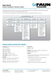
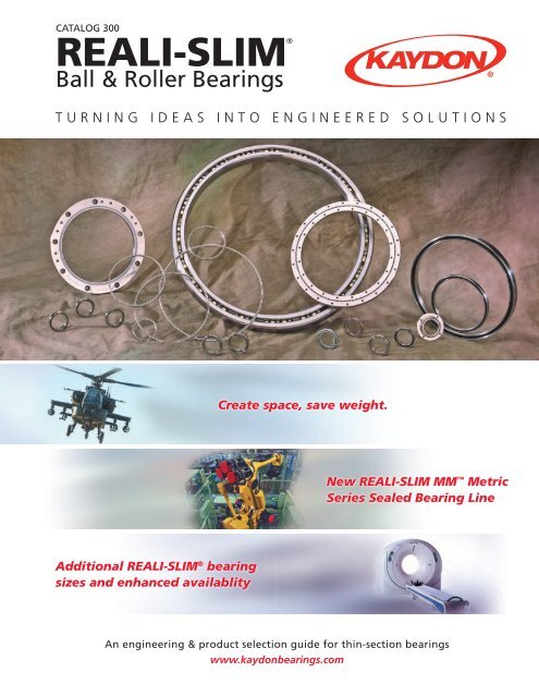
<strong>Catalog</strong> <strong>300</strong><br />
Reali-Slim®<br />
Ball & Roller <strong>Bearings</strong><br />
Turning Ideas into Engineered Solutions<br />
Create space, save weight.<br />
New REALI-SLIM MM Metric<br />
Series Sealed Bearing Line<br />
Additional REALI-SLIM ® bearing<br />
sizes and enhanced availablity<br />
An engineering & product selection guide for thin-section bearings<br />
www.kaydonbearings.com
REALI-SLIM ® <strong>Bearings</strong> <strong>Catalog</strong> <strong>300</strong> ©KAYDON ® Corporation Issue 10<br />
Identification of<br />
REALI-SLIM ® <strong>Bearings</strong><br />
REALI-SLIM ® bearings are marked for complete<br />
identification with an (8) or (9) digit part number.<br />
Positions 1-8 identify materials, size, type, and precision.<br />
Position 9 (optional) identifies non-standard internal fit.<br />
Part Number Code Example<br />
Position 1 2 3 4 5 6 7 8 9 10-13<br />
Nomenclature Material Series Size Type Separator Precision Internal Fit DFAR Compliance<br />
Example K G 1 2 0 X P 0 L -USA<br />
Position 1 – Material<br />
Races/Balls<br />
A AISI 52100 Steel<br />
B AISI 52100 Steel<br />
D AISI 52100 Steel<br />
E AISI 52100 Steel<br />
Seals, Shields<br />
with One seal—PTFE<br />
with Two seals—PTFE<br />
with One shield<br />
with Two shields<br />
F AISI 52100 Steel with One seal—Nitrile rubber<br />
L A laMI-SEAL ®<br />
G AISI 52100 Steel with Two seals—Nitrile rubber<br />
L A laMI-SEAL ®<br />
H AISI 52100 Steel<br />
J AISI 52100 Steel<br />
K AISI 52100 Steel<br />
L AISI 52100 Steel<br />
M M-50 Steel<br />
N AISI 52100 Steel<br />
P AISI 17-4PH Steel<br />
Q AISI 52100 Steel<br />
S AISI 440C Stainless Steel<br />
with One seal—Nitrile rubber<br />
with Two seals—Nitrile rubber<br />
with No seals or shields<br />
with Two seals and<br />
ENDURAKOTE ® plating<br />
with No seals or shields<br />
with No seals and<br />
ENDURAKOTE ® plating<br />
with Ceramic Balls<br />
(see Section 6)<br />
with No shields or seals<br />
(see section 6)<br />
with No seals or shields<br />
Position 2 – Series Cross Section<br />
Radial Thickness<br />
Width<br />
Standard a *.187 x .187<br />
Cross-Sections or .250 x .250<br />
B .312 x .312<br />
C .375 x .375<br />
D .500 x .500<br />
E .625 x .625<br />
F .750 x .750<br />
g 1.000 x 1.000<br />
Extended Width H *.187 x .250<br />
or .250 x .312<br />
I .312 x .375<br />
J .375 x .437<br />
K .500 x .578<br />
l .625 x .727<br />
M .750 x .875<br />
N 1.000 x 1.187<br />
Extra-Extended S *.187 x .312<br />
Width or .250 x .375<br />
t .312 x .437<br />
U .375 x .500<br />
V .500 x .656<br />
W .625 x .828<br />
X .750 x 1.000<br />
Y 1.000 x 1.375<br />
T AISI 440C Stainless Steel<br />
U AISI 440C Stainless Steel<br />
V AISI 440C Stainless Steel<br />
W AISI 440C Stainless Steel<br />
X AISI 52100 Steel<br />
Y AISI 440C Stainless Steel<br />
Z Other<br />
with One seal—PTFE<br />
with Two seals—PTFE<br />
with Two shields<br />
with Two seals—Nitrile rubber<br />
with Ceramic Balls<br />
with Ceramic Balls<br />
(see Section 6)<br />
*Smaller section applies when position 3 is alphabetic—see<br />
following explanations of positions 3, 4, and 5.<br />
2 | www.kaydonbearings.com 1-800-514-3066
©KAYDON ® Corporation Issue 10 REALI-SLIM ® <strong>Bearings</strong> <strong>Catalog</strong> <strong>300</strong><br />
Identification of REALI-SLIM ® <strong>Bearings</strong> (continued)<br />
Position 3, 4 and 5—Size (Bearing Bore)<br />
Numeric Characters<br />
Nominal bearing bore in inches multiplied by ten<br />
Alphabetic Characters<br />
“A” In Position 3 in combination with “A” in Position 2<br />
denotes .187 x .187 Series<br />
“A” In Position 3 in combination with “H” in Position 2<br />
denotes .187 x .250 Series<br />
“A” In Position 3 in combination with “S” in Position 2<br />
denotes .187 x .312 Series<br />
Examples<br />
040 = 4.0" Bore<br />
120 = 12.0" Bore<br />
400 = 40.0" Bore<br />
“10” following “AA” in Positions 2 & 3 =<br />
.187 x .187 Series with 1.0" Bore<br />
“15” following “HA” in Positions 2 & 3 =<br />
.187 x .250 Series with 1.5" Bore<br />
Position 6—Bearing Type (see Section 3)<br />
A Angular contact single bearing (not ground for<br />
universal duplexing)<br />
B Angular contact pair—duplexed back to back<br />
C Radial contact<br />
F Angular contact pair—duplexed face to face<br />
T Angular contact pair—duplexed tandem<br />
U Angular contact single bearing—ground for universal<br />
duplexing<br />
X Four-point contact<br />
Z Other<br />
Position 7—Separator (see Section 4)<br />
C Non-metallic composite, segmental, “snap-over” type<br />
D Phenolic laminate, one-piece ring “snap-over” type<br />
E Brass, segmental “snap-over” type<br />
F Full complement bearing—no separator<br />
G Nylon one-piece ring, circular pocket<br />
H Phenolic laminate, one-piece ring with circular pockets<br />
J Nylon strip separator, circular pockets<br />
K Phenolic laminate, riveted two-piece ring<br />
L Nylon, one-piece ring “snap-over” type<br />
M Formed wire, strip or segmental, “snap-over” type,<br />
ball in every pocket<br />
N Nylon, “snap-over” type<br />
P Standard formed ring “snap-over” type (material—<br />
brass or non-metallic composite)<br />
Q Peek, one-piece ring, circular pocket<br />
R Standard formed ring, circular pocket (material—brass<br />
or non-metallic composite)<br />
S Helical coil springs<br />
T Stainless steel, formed ring “snap-over” type<br />
U Stainless steel, formed ring circular pockets<br />
V Brass, formed ring, “snap-over” type<br />
W Formed wire, strip or segmental, “snap-over” type<br />
X Peek, one-piece, “snap-over” pocket<br />
Y Brass, formed ring, circular pockets<br />
Z Other (toroids, slugs, spacer balls or others available)<br />
Position 8—Precision (see Section 3)<br />
(ABEC Specifications are per ABMA Standard 26.2)<br />
0 KAYDON Precision Class 1 per ABEC 1F<br />
1 KAYDON Precision Class 1 with Class 4 Runouts<br />
2 KAYDON Precision Class 1 with Class 6 Runouts<br />
3 KAYDON Precision Class 3 per ABEC 3F<br />
4 KAYDON Precision Class 4 per ABEC 5F<br />
6 KAYDON Precision Class 6 per ABEC 7F<br />
8 Other<br />
Position 9—Bearing Internal Fit<br />
A .0000 to .0005 Clearance<br />
B .0000 to .0010 Clearance<br />
C .0005 to .0010 Clearance<br />
D .0005 to .0015 Clearance<br />
E .0010 to .0020 Clearance<br />
F .0015 to .0025 Clearance<br />
G .0020 to .0030 Clearance<br />
H .0030 to .0040 Clearance<br />
I .0040 to .0050 Clearance<br />
J .0050 to .0060 Clearance<br />
K .0000 to .0005 Preload<br />
L .0000 to .0010 Preload<br />
M .0005 to .0010 Preload<br />
N .0005 to .0015 Preload<br />
P .0010 to .0020 Preload<br />
Q .0010 to .0015 Preload<br />
R .0015 to .0025 Preload<br />
S .0020 to .0030 Preload<br />
Z Other clearance or preload not specified above<br />
• Type X or C = Diametral Preload or Clearance<br />
• Duplexed Type A = Axial Preload or Clearance<br />
Note: Above internal bearing fits apply to unmounted<br />
bearings only. Mounting fits can greatly affect final internal<br />
bearing fit.<br />
Position 10-13—DFAR Compliance<br />
All Reali-Slim ® bearings requiring compliance with<br />
Defense Federal Acquisition Regulations (DFAR)<br />
"Specialty Metals" and "the Restrictions on Acquisition<br />
of Ball and Roller <strong>Bearings</strong>" clauses will contain ‘-USA’ in<br />
positions 10-13. If internal fit is not called out in position<br />
9, it will also contain a dash.<br />
Example #1: KG120XP0L-USA<br />
Example #2: KG120XP0--USA<br />
1-800-514-3066 www.kaydonbearings.com |3
REALI-SLIM ® <strong>Bearings</strong> <strong>Catalog</strong> <strong>300</strong> ©KAYDON ® Corporation Issue 10<br />
REALI-SLIM ® — The Industry Leader<br />
in Thin-Section <strong>Bearings</strong><br />
REALI-SLIM ® thin-section bearings are known around<br />
the world for creating design space and saving weight.<br />
Design engineers across a wide spectrum of industries<br />
have trusted KAYDON since 1941 for precision and<br />
reliability in the most demanding applications.<br />
<strong>Catalog</strong> <strong>300</strong> has been relied upon for nearly as long,<br />
providing users with the specifications, capacities and<br />
sizing charts to choose the right bearing for their needs.<br />
Every edition offers more choices than ever, and this<br />
update is no exception.<br />
What’s New<br />
New Line of Sealed<br />
REALI-SLIM MM Metric<br />
Series <strong>Bearings</strong><br />
■■ We are pleased to introduce a new 8mm series<br />
of sealed metric REALI-SLIM® bearings in both<br />
Type C (Radial Contact) and Type X (Four-Point<br />
Contact). Choose from 28 new part numbers,<br />
in bore sizes from 25mm up to 170mm. This<br />
new series gives you more versatility when<br />
your design calls for a sealed bearing.<br />
Expanded Range of JG Series<br />
Sealed REALI-SLIM ® <strong>Bearings</strong><br />
®<br />
■ ■ The JG series of sealed REALI-SLIM bearings<br />
has added 12 new part numbers to its<br />
line-up, with new bore sizes from 7.0 inches<br />
to 11.0 inches. The JU and JG series now span<br />
a range from 7.0 inches to 40.0 inches.<br />
Handy Conversion Table on<br />
Inside Back Cover<br />
■■ To save you a step and make the catalog even<br />
more useful, we've added a table of English-<br />
Metric equivalents commonly used by design<br />
engineers.<br />
More REALI-SLIM ® Part Numbers<br />
Available From Stock<br />
■■ Availability from stock has been enhanced for<br />
more than a dozen part numbers since the<br />
last catalog revision in 2007.<br />
Easier REALI-SLIM ® Part Number<br />
Identification<br />
®<br />
■ ■ REALI-SLIM part number tables have been<br />
relocated to the inside front cover, so you can<br />
find them immediately.<br />
For latest releases — catalog, software, or<br />
CAD drawing downloads — visit our website<br />
www.kaydonbearings.com.<br />
4 | www.kaydonbearings.com 1-800-514-3066
©KAYDON ® Corporation Issue 10 REALI-SLIM ® <strong>Bearings</strong> <strong>Catalog</strong> <strong>300</strong><br />
Table of Contents<br />
Page<br />
Number<br />
Section 1— An Introduction to REALI-SLIM ® Thin-Section <strong>Bearings</strong>..................................................... 7<br />
• Product Line Overview.......................................................................................................................8<br />
• Examples of Design Efficiency...........................................................................................................9<br />
• Bearing Load Scenarios.....................................................................................................................10<br />
• General Information and Availability Chart...................................................................................12<br />
• General Specifications for Standard <strong>Bearings</strong>................................................................................13<br />
Section 2— Selection Tables for Standard REALI-SLIM ® <strong>Bearings</strong>....................................................... 14<br />
®<br />
• Standard Open REALI-SLIM Inch Series <strong>Bearings</strong>, AISI 52100: Types A, C, X..............................15<br />
®<br />
• Sealed REALI-SLIM <strong>Bearings</strong>, AISI 52100: Types C, X.....................................................................27<br />
• ENDURAKOTE ®<br />
-plated ENDURA-SLIM ® <strong>Bearings</strong> ..........................................................................35<br />
®<br />
• Stainless Steel Open REALI-SLIM <strong>Bearings</strong>, AISI 440C: Types A, C, X...........................................49<br />
<br />
• REALI-SLIM MM Metric Series <strong>Bearings</strong>.........................................................................................53<br />
®<br />
• ULTRA-SLIM Series <strong>Bearings</strong>............................................................................................................60<br />
®<br />
• REALI-SLIM TT Turntable Series <strong>Bearings</strong>......................................................................................62<br />
Section 3— Applications Engineering.................................................................................................... 65<br />
• Selection Recommendations............................................................................................................66<br />
• Capacity, Life, and Load Analysis.....................................................................................................71<br />
• Mounting Recommendations...........................................................................................................75<br />
• Precision Classes and Tolerances......................................................................................................80<br />
Section 4— Separator Types, Ball Count, and Performance................................................................ 92<br />
• Separator Types..................................................................................................................................93<br />
• Number of Balls in Standard <strong>Bearings</strong>.............................................................................................97<br />
• Limiting Speeds..................................................................................................................................98<br />
• Torque................................................................................................................................................100<br />
• Axis Deviations..................................................................................................................................102<br />
• Deflection Curves..............................................................................................................................104<br />
Section 5— Installation and Maintenance of REALI-SLIM ® Thin-Section <strong>Bearings</strong>........................... 110<br />
• Inspection and Installation Procedures..........................................................................................111<br />
• Lubrication and Maintenance.........................................................................................................113<br />
Section 6— Other Products..................................................................................................................... 115<br />
• Metric BB Series <strong>Bearings</strong>.................................................................................................................116<br />
• <strong>Bearings</strong> for Demanding Applications...........................................................................................119<br />
• KT Series Tapered Roller <strong>Bearings</strong>...................................................................................................121<br />
Section 7— Appendix and Sales Information...................................................................................... 122<br />
• Terms and Definitions......................................................................................................................123<br />
• Warranty Information and Legal Notices.......................................................................................124<br />
• Design Aids and Technical Literature.............................................................................................127<br />
• Request for Bearing Proposal Data Form.......................................................................................129<br />
• Conversion Factors............................................................................................................................131<br />
The design and application information contained in this catalog is for illustration only. Responsibility for the application<br />
of the products contained in this catalog rests solely with the equipment designer or user. In spite of our best efforts, the<br />
material contained in this catalog may contain inaccuracies and typographical errors.<br />
1-800-514-3066 www.kaydonbearings.com |5
REALI-SLIM ® <strong>Bearings</strong> <strong>Catalog</strong> <strong>300</strong> ©KAYDON ® Corporation Issue 10<br />
REALI-SLIM ® ... For Compact,<br />
Lightweight Designs of the Future.<br />
Semiconductor<br />
Fabrication Equipment<br />
Machine Tools<br />
• Aerospace and astronomy<br />
instrumentation<br />
• Fixturing and workholding<br />
equipment<br />
• Food processing equipment<br />
• Glassworking equipment<br />
• Index and rotary tables<br />
• Packaging equipment<br />
• Machine tools<br />
• Medical devices<br />
• Optical scanning equipment<br />
• Tire making equipment<br />
• Radar, satellite and<br />
communications equipment<br />
• Robotics<br />
• Textile machinery<br />
• Tube and pipe cutting machines<br />
• Semiconductor manufacturing<br />
equipment<br />
• Sorting equipment<br />
Radar<br />
Robotic Silicon Wafer Processing<br />
Rotary Table<br />
Armored Vehicle Sights & FLIRs<br />
Textile Printer<br />
KAYDON REALI-SLIM ® bearings were designed to<br />
fill the need for a fully hardened, thin-section, antifriction<br />
bearing—a need resulting from the modern<br />
design concepts of simplicity, miniaturization, weight<br />
reduction, and compactness being applied to a wide<br />
variety of rotating devices.<br />
Before the introduction of REALI-SLIM ® bearings,<br />
6 | www.kaydonbearings.com 1-800-514-3066<br />
designers were forced to use bushings or select bearings<br />
from the lightest bearings then commercially available,<br />
the standard “Light”, “Extra-Light”, and “Extremely<br />
Light” series—many of which often had undesirable<br />
cross sections, and excess weight.<br />
REALI-SLIM ® bearings overcome the problems of excess<br />
weight and size in bearings, shafts, and housings.
©KAYDON ® Corporation Issue 10 REALI-SLIM ® <strong>Bearings</strong> <strong>Catalog</strong> <strong>300</strong><br />
Section 1 — An Introduction to REALI-SLIM ®<br />
Thin-Section <strong>Bearings</strong><br />
Page<br />
Number<br />
• Product Line Overview....................................................................... 8<br />
• Examples of Design Efficiency........................................................... 9<br />
• Bearing Load Scenarios.................................................................... 10<br />
• Product Availability Chart................................................................ 12<br />
• Specifications for Standard <strong>Bearings</strong>.............................................. 13<br />
1-800-514-3066 www.kaydonbearings.com |7
Section 1–Introduction<br />
REALI-SLIM ® <strong>Bearings</strong> <strong>Catalog</strong> <strong>300</strong> ©KAYDON ® Corporation Issue 10<br />
Product Line Overview<br />
The REALI-SLIM ® product line consists of a family<br />
of seven open (Figure 1-1) and five sealed (Figure<br />
1-2) series of thin-section bearings ranging in bore<br />
diameters from 1.000 inch to 40.000 inches. Series<br />
range from .187 x .187 inch to 1.000 x 1.000 inch in<br />
cross section. Open bearings are available from stock<br />
in three configurations (Types A, C & X). Stock sealed<br />
bearings are available in Types C & X only.<br />
We can provide internal fit up, lubricants, separators<br />
and other features to meet the most demanding<br />
specifications. To obtain corrosion resistance<br />
consider using KAYDON stainless steel REALI-SLIM ®<br />
or ENDURA-SLIM ® series of bearings. ENDURAKOTE ®<br />
plating provides corrosion protection equal to or<br />
better than a full AISI 440C stainless steel bearing and<br />
can be supplied with very quick delivery.<br />
Additional product line variants include: REALI-SLIM MM <br />
metric series bearings, ULTRA-SLIM ® bearings, and<br />
REALI-SLIM TT ® series turntable bearings (Section 2); and<br />
BB metric ball bearings, <strong>Bearings</strong> for Demanding<br />
Applications, and KT thin-section taper bearings<br />
(Section 6).<br />
Within these families, you can generally choose<br />
between open bearings for applications where<br />
bearings will not be exposed to damaging particulates<br />
and sealed bearings for applications where bearings<br />
need to be kept clean and well-lubricated.<br />
To support various load scenarios, REALI-SLIM ®<br />
bearings are available in three basic types: radial<br />
contact (Type C), angular contact (Type A), and fourpoint<br />
contact (Type X)—see pages 10 and 11 for<br />
explanations on each type—and in a variety of sizes,<br />
or series (e.g., KA, KB, KC, etc.).<br />
REALI-SLIM ® bearings are available with various<br />
separator options to space the rolling elements<br />
uniformly and prevent contact between them.<br />
Separator types available include: continuous ring<br />
“snap-over pocket”, continuous ring circular pocket,<br />
formed wire, toroid, PTFE spacers, and spacer ball<br />
separators. See Section 4 for complete details.<br />
SPECIFICATION CONTROL<br />
In today’s world, product traceability is extremely<br />
important. To satisfy these requirements, requesting<br />
a “specification control drawing” for a REALI-SLIM ®<br />
bearing is a valuable option to consider.<br />
A specification control drawing provides the user a<br />
concise description of the important bearing features<br />
and parameters for a specific bearing. a specification<br />
control drawing request will generate a unique<br />
part number for the standard REALI-SLIM ® bearing,<br />
including the commercially available options you have<br />
selected. this provides the customer quick and easy<br />
identification of product in the field as well as a concise<br />
receiving and inspection document for the factory.<br />
The Product Line At a Glance<br />
Open <strong>Bearings</strong> — Figure 1-1<br />
Series AA<br />
Series A<br />
1<br />
⁄4 " x 1 ⁄4 "<br />
Series B<br />
5<br />
⁄16 " x 5 ⁄16 "<br />
3<br />
⁄16 " x 3 ⁄16 " Sealed <strong>Bearings</strong> — Figure 1-2<br />
Series C Series D Series F<br />
Series G<br />
3<br />
⁄8 " x 3 ⁄8 " 1<br />
⁄2 " x 1 ⁄2 " 3<br />
⁄4 " x 3 ⁄4 " 1" x 1"<br />
Series JHA<br />
3<br />
⁄16 " x 1 ⁄4 "<br />
Series JA Series JB Series JU Series JG<br />
1<br />
⁄4 " x 1 ⁄4 " 5<br />
⁄16 " x 5 ⁄16 " 1<br />
⁄2 " x 3 ⁄8 " 1" x 1"<br />
8| www.kaydonbearings.com 1-800-514-3066
Design Efficiency<br />
REALI-SLIM ® <strong>Bearings</strong> Improve<br />
Design Efficiency<br />
In REALI-SLIM ® bearings, each series is<br />
based on a single cross section which<br />
remains constant as the bore diameter<br />
is increased. This is in sharp contrast to<br />
standard bearings in which the cross<br />
section increases as the bore diameter<br />
increases. The constant cross section of<br />
a REALI-SLIM ® bearing is of particular<br />
value when designing a product which<br />
will be manufactured in various sizes<br />
based on shaft diameter and power<br />
requirements (Figure 1-3). By using the<br />
same series of REALI-SLIM ® bearings<br />
throughout a product line, the designer<br />
can standardize on common components.<br />
For all diameters of this rotary table your<br />
bearing envelope stays the same.<br />
©KAYDON ® Corporation Issue 10 REALI-SLIM ® <strong>Bearings</strong> <strong>Catalog</strong> <strong>300</strong><br />
For all diameters of this<br />
rotary table your bearing<br />
envelope stays the same.<br />
Figure 1-3<br />
Example 30" diameter<br />
Example 12" diameter<br />
Example 4" diameter<br />
Section 1–Introduction<br />
REALI-SLIM ® <strong>Bearings</strong> Make a More Compact Design<br />
Additional advantages in application design made<br />
possible by REALI-SLIM ® bearings can be seen by<br />
referring to Figures 1-4, 1-5, and 1-6. A large bore,<br />
small cross-section REALI-SLIM ® bearing permits the<br />
use of a large diameter hollow shaft (Figure 1-5)<br />
in place of a smaller diameter solid shaft (Figure<br />
1-4), king-post design. Components such as air and<br />
hydraulic lines or electrical wiring and slip rings can<br />
then be accommodated within the hollow shaft,<br />
resulting in a neater, more efficient design.<br />
In many applications, a single four-point contact<br />
REALI-SLIM ® bearing (Figure 1-6) can replace two<br />
bearings (Figures 1-4 and 1-5) compacting the design<br />
and simplifying the bearing mounting. Besides the<br />
obvious cost savings of eliminating one bearing, this<br />
arrangement also creates space and saves weight. The<br />
use of REALI-SLIM ® bearings also provides a stiffer<br />
structure by using large diameter hollow tubes to<br />
replace solid shafts and by supporting the rotating<br />
structure (table) at the periphery.<br />
Figure 1-4<br />
Figure 1-5 Figure 1-6<br />
1-800-514-3066 www.kaydonbearings.com |9
Section 1–Introduction<br />
REALI-SLIM ® <strong>Bearings</strong> <strong>Catalog</strong> <strong>300</strong> ©KAYDON ® Corporation Issue 10<br />
REALI-SLIM ® Bearing Types<br />
Support All Load Scenarios<br />
Radial and Axial (Thrust) Loads<br />
Types of REALI-SLIM ® <strong>Bearings</strong><br />
<strong>Bearings</strong> support a shaft or housing to permit their free<br />
motion about an axis of rotation. Load can be applied<br />
to bearings in either of two basic directions (Figure 1-7).<br />
Radial loads act at right angles to the shaft (bearing’s<br />
axis of rotation). Axial (thrust) acts parallel to the axis of<br />
rotation. When these loads are offset from either the<br />
bearing axis (distance St) or radial plane (distance Sr), a<br />
resulting moment load (M) will be created. KAYDON<br />
REALI-SLIM ® bearings are available in a variety of types<br />
to handle radial loads, axial loads and moment loads.<br />
Figure 1-7<br />
REALI-SLIM ® bearings are available in three basic<br />
configurations: radial (Type C), angular contact (Type<br />
A), and four-point contact (Type X).<br />
REALI-SLIM ® Bearing Types<br />
A = angular<br />
C = radial<br />
X = four-point<br />
By using these three types, the customer has a wider<br />
choice of mounting arrangements to meet load, stiffness<br />
and accuracy requirements in the most efficient manner.<br />
Force T<br />
(Thrust)<br />
Radial<br />
Plane<br />
Sr<br />
Force R<br />
+<br />
+<br />
Axis of<br />
Rotation<br />
Radial Contact Bearing (Type C)<br />
The Type C Radial Contact Bearing (Figure 1-8) is a<br />
single row radial ball bearing of conventional design.<br />
It is a Conrad-type assembly, which means that it is<br />
assembled by eccentric displacement of the inner race<br />
within the outer race which permits insertion of about<br />
half of a full complement of balls.<br />
St<br />
REALI-SLIM ® TYPE C<br />
Radial<br />
Figure 1-8<br />
Outer Race<br />
Resultant<br />
M<br />
The resultant moment load (M) equation:<br />
M = (± T) (S t ) + (± R) (S r )<br />
Ball<br />
Snap-over Separator<br />
Inner Race<br />
Although the Type C bearing is designed primarily for<br />
radial load application, it can be configured to accept<br />
some axial (thrust) load in either direction. But, if thrust<br />
is a concern, a set of angular contact bearings should be<br />
considered for the specific application.<br />
10 | www.kaydonbearings.com 1-800-514-3066
Angular Contact Bearing (Type A)<br />
The Type A Bearing is also a conventional design. It<br />
features a circular pocket separator and a 30° contact<br />
angle (see Figure 1-9) along with approximately 67% of<br />
a full complement of balls.<br />
The chief benefit of the Type A bearing is that it<br />
provides greater thrust capacity than a Type C or Type<br />
X bearing. Because of its counterbored outer race,<br />
Type A bearings have unidirectional thrust capacity.<br />
Thus, this bearing should be mounted opposed to<br />
another bearing to establish and maintain the contact<br />
angle, and to support reversing thrust loads.<br />
REALI-SLIM ® TYPE A<br />
Figure 1-9<br />
©KAYDON ® Corporation Issue 10 REALI-SLIM ® <strong>Bearings</strong> <strong>Catalog</strong> <strong>300</strong><br />
REALI-SLIM ® Bearing Types Support All Load Scenarios (continued)<br />
Contact<br />
Angle<br />
Four-Point Contact Bearing (Type X)<br />
Standard bearing lines are most often designed to<br />
handle either radial or axial load conditions. The<br />
unique feature about the KAYDON REALI-SLIM ® Type X<br />
four-point contact bearing line (see Figure 1-10) is that<br />
the gothic arch geometry of the inner and outer races<br />
enables a single bearing to carry three types of loading<br />
(radial, axial and moment) simultaneously. This makes<br />
it the bearing of choice for many applications since a<br />
single four-point contact bearing can often replace two<br />
bearings, providing a simplified design.<br />
Type X bearings may also be furnished with an internal<br />
diametral preload for those applications requiring<br />
greater stiffness or zero free play. This is accomplished<br />
by using balls that are larger than the space provided<br />
between the raceways. The balls and raceways,<br />
therefore, have some elastic deformation in the<br />
absence of an external load.<br />
Section 1–Introduction<br />
Outer Race<br />
Ball<br />
Circular Pocket<br />
Separator<br />
Inner Race<br />
REALI-SLIM ® TYPE X<br />
Figure 1-10<br />
Outer Race<br />
Ball<br />
Snap-over Separator<br />
Contact Angle<br />
Inner Race<br />
NOTE: KAYDON does not recommend the use of two<br />
Type X bearings on a common shaft, as it could result in<br />
objectionable friction torque.<br />
1-800-514-3066 www.kaydonbearings.com |11
Section 1–Introduction<br />
REALI-SLIM ® <strong>Bearings</strong> <strong>Catalog</strong> <strong>300</strong> ©KAYDON ® Corporation Issue 10<br />
General Information<br />
and Availability Chart<br />
Standard REALI-SLIM ® <strong>Bearings</strong>—are those listed in the data sheets, acceptance testing, etc.<br />
Series Data Tables. They are manufactured to KAYDON REALI-SLIM ® <strong>Bearings</strong>—with non-standard materials,<br />
Precision Class 1 and the specifications on page 13. New sizes, tolerances, specifications, and features are available.<br />
sizes are added to stock periodically and updated on We will be pleased to quote on your requirements.<br />
our website. Be sure to visit www.kaydonbearings.com<br />
Order REALI-SLIM<br />
for latest information.<br />
® <strong>Bearings</strong>—by bearing numbers<br />
shown in Series Data Tables.<br />
Options<br />
Assistance—in bearing selection will be furnished<br />
REALI-SLIM ® <strong>Bearings</strong>—can be optimized for your special by our regional sales managers or the KAYDON<br />
requirements. Standard commercial options include: Engineering Department upon request.<br />
changes in diametral clearance, preloading, lubricants, Changes—KAYDON reserves the right to change<br />
packaging, etching of high points, tagging bearings with specifications and other information included in this<br />
actual dimensions as requested, separators, duplexing, catalog without notice.<br />
Figure 1-11<br />
This table applies to AISI 52100 standard bearings. For stainless steel, please see Section 2.<br />
Series Type<br />
Bore Diameter In Inches<br />
1 1 1 ⁄2 1 3 ⁄4 2 2 1 ⁄2 3 3 1 ⁄2 4 4 1 ⁄4 4 1 ⁄2 4 3 ⁄4 5 5 1 ⁄2 6 6 1 ⁄2 7 7 1 ⁄2 8 9 10 11 12 14 16 18 20 21 22 25 30 35 40<br />
JHA Series A<br />
3<br />
⁄16" Radial C<br />
Section X<br />
•<br />
•<br />
•<br />
•<br />
•<br />
•<br />
3<br />
Section X • • •<br />
KAA Series<br />
⁄16" Radial<br />
A<br />
C<br />
•<br />
•<br />
•<br />
•<br />
•<br />
•<br />
JA Series A<br />
1<br />
⁄4" Radial C • • • • • • • ] • ] ] ]<br />
Section X • • • • • • • ] • ] • •<br />
KA Series A • • • • • • • • • • • • • • • ] • ] ]<br />
1<br />
⁄4" Radial C • • • • • • • • • • • • • • • • • ] •<br />
Section X • • • • • • • • • • • • • • • • • ] •<br />
JB Series A<br />
5<br />
⁄16" Radial C • • • • • • • ] ] ] ] ]<br />
Section X • • • • • • • ] ] ] ] ]<br />
KB Series A • • • • • • • ] ] • • ] ] ] ] • ] ] ] ] ] ] ]<br />
5<br />
⁄16" Radial C • • • • • • • ] • ] • • ] ] • ] ] ] ] ] ] ] ]<br />
Section X • • • • • • • ] • • • • ] ] • • ] ] ] ] • ] ]<br />
KC Series A • ] • • • • • ] • ] • ] ] ] ] ] ] ] ] ] ]<br />
3<br />
⁄8" Radial C • • • • • • • • • • • • • ] • • • ] ] ] ]<br />
Section X • ] • • • • • • • ] • • • • • • • ] ] ] ]<br />
JU Series A<br />
3<br />
⁄8" Radial C • ] • • • • • • • • • • • • ]<br />
Section X • • • • • • • • • • • • • • ]<br />
KD Series A • • • • • • • • • • • • ] ] • ] ] ] ] ] ] ]<br />
1<br />
⁄2" Radial C • • • • • • • • • • • • • • • • • ] ] ] ] ]<br />
Section X • • • • • • • • • • • • • • • • ] • • ] • ]<br />
KF Series A ] ] ] • ] • • • ] • • • • ] • ] ] ] ] ] ] ] ]<br />
3<br />
⁄4" Radial C • • • • • • • • • • • • • • • ] ] ] ] ] ] ] ]<br />
Section X • • • • • • • • • • • • • • • • • ] ] ] ] ] ]<br />
JG Series A<br />
1" Radial C ] ] ] ] ] ] ] ] ] ] ] ] ] ] ] ]<br />
Section X ] ] ] ] ] ] ] ] ] ] ] ] ] ] ] ]<br />
KG Series A ] ] ] ] ] ] • ] ] • • • • ] • • • • • ] ] ] • ]<br />
1" Radial C ] ] ] ] • ] • • • • • • • • • • • • • ] • ] ] ]<br />
Section X ] ] ] ] • ] • ] • • • • • • • • • • • • • • • •<br />
• Available from stock. ] Limited Availability – contact KAYDON for lead time and minimum purchase requirement.<br />
12 | www.kaydonbearings.com 1-800-514-3066
Specifications for Standard<br />
REALI-SLIM ® <strong>Bearings</strong><br />
©KAYDON ® Corporation Issue 10 REALI-SLIM ® <strong>Bearings</strong> <strong>Catalog</strong> <strong>300</strong><br />
ITEM DESCRIPTION REFERENCE SPECIFICATION<br />
MATERIAL ANALYSIS<br />
RACES & BALLS AISI 52100 Type Steel Vacuum Degassed aSTM A-295, AMS-STD-66<br />
A aISI 440C Stainless Steel A aSTM A-756<br />
SEPARATORS P Type—Brass or Non-metallic composite aSTM B-36 or B-134<br />
C, X BEARINGS L Type—Nylon, Fiberglass Reinforced<br />
Section 1–Introduction<br />
A BEARINGS R Type—Brass or Non-metallic composite aSTM B-36 or B-134<br />
G<br />
g Type—Nylon, Fiberglass Reinforced<br />
SEALS Nitrile Rubber, 70 Durometer, Steel Reinforced MIL-R 6855<br />
RACES<br />
HEAT TREATMENT<br />
through hardened and dimensionally stabilized for use<br />
from -65°F to +250°F (-54°C to +121°C)<br />
BALLS aISI 52100—Hardened to Rc 62-66, AISI 440C—to Rc 58-65<br />
PRECISION<br />
RACE DIMENSIONS KAYDON Precision Class 1 aBMA ABEC-1F or better<br />
RACE RUNOUTS KAYDON Precision Class 1 aBMA ABEC-1F or better<br />
BALLS aBMA Grade 10 aNSI/ABMA/ISO 3290<br />
TYPE C BEARING<br />
TYPE X BEARING<br />
TYPE A BEARING<br />
DIAMETRAL CLEARANCE<br />
AND CONTACT ANGLE<br />
Sufficient diametral clearance to provide small amount of<br />
running clearance after installation with recommended fits<br />
Gothic Arch Form for two 30° contact angles under light<br />
radial gaging load. Sufficient diametral clearance to<br />
provide clearance after installation with recommended fits aBMA Standard 26.2<br />
Diametral clearance for 30° contact angle in single<br />
unmounted bearing under light axial gaging load. Wide<br />
range of preload or running clearance for matched sets<br />
SEPARATOR DESIGN<br />
P & L TYPES<br />
C, X BEARINGS Circular Ring, Snapped Over Balls for Retention<br />
R & G TYPES<br />
A BEARINGS Circular Ring, Circular Pockets, Self Retained<br />
QUALITY CONTROL<br />
G<br />
OTHER<br />
KAYDON Quality Control procedures have been approved<br />
by major aerospace industries and agencies of the U.S. ISO 9001<br />
government<br />
IDENTIFICATION Marked on Bearing O.D.: Cage Code, “KAYDON” ® , MIL-STD-130<br />
Part Number and Date Code<br />
CLEANING<br />
PRESERVATIVE<br />
PACKAGING<br />
Multiple cycle immersion and agitation in solvents<br />
and/or aqueous cleaners<br />
Preservative Oil<br />
Heat Sealed in Plastic Bag & Boxed<br />
NOTE—Also available: Quality Control per MIL-Q-9858, Packaging and Lubrication options, and “Clean Room” Facilities.<br />
1-800-514-3066 www.kaydonbearings.com |13
REALI-SLIM ® ® <strong>Bearings</strong> <strong>Catalog</strong> <strong>300</strong> <strong>300</strong> ©KAYDON ® ® Corporation Issue Issue 10 10<br />
Section 2 — Selection Tables for Standard<br />
REALI-SLIM ® <strong>Bearings</strong><br />
Page<br />
Number<br />
• Open <strong>Bearings</strong> Inch Series – AISI 52100,<br />
Selection Tables - Types A, C, X........................................................ 15<br />
• Sealed <strong>Bearings</strong> – AISI 52100,<br />
Selection Tables - Types C, X............................................................. 27<br />
®<br />
• ENDURAKOTE - Plated <strong>Bearings</strong><br />
Overview & Selection Tables............................................................ 35<br />
• Open <strong>Bearings</strong> - AISI 440C, Overview &<br />
Selection Tables - Types A, C, X........................................................ 49<br />
• Open <strong>Bearings</strong> Metric Series - AISI 52100,<br />
Selection Tables - Types A, C, X........................................................ 53<br />
®<br />
• ULTRA-SLIM <strong>Bearings</strong> Overview &<br />
Selection Tables - Types A, C, X........................................................ 60<br />
®<br />
• REALI-SLIM TT Turntable Series<br />
Overview & Selection Tables............................................................ 62<br />
14 | www.kaydonbearings.com 1-800-514-3066
©KAYDON ® Corporation Issue 10 REALI-SLIM ® <strong>Bearings</strong> <strong>Catalog</strong> <strong>300</strong><br />
Open REALI-SLIM ® Bearing Selections<br />
Type A<br />
Angular Contact<br />
A deep groove bearing with reduced shoulder on one<br />
side of inner or outer race ball path. Snapover assembly<br />
permits use of a one-piece circular pocket ring separator<br />
and greater ball complement. These bearings will<br />
accept radial load and single direction thrust load and<br />
are normally used in conjunction with another bearing<br />
of similar construction. Type A bearings require the<br />
application of thrust to establish contact angle. Stock<br />
bearings are individual units and when purchased as<br />
such must be adjusted at installation to desired running<br />
clearance or preload. If preferred, matched sets are<br />
available. KAYDON also offers matched spacers for<br />
applications requiring extra precision. KAYDON ® can<br />
provide this service direct from the factory.<br />
Section 2–Selection Tables<br />
KAYDON<br />
Bearing<br />
Number<br />
Bore<br />
KAA Series<br />
Dimensions in Inches Capacities in Pounds Approx.<br />
Weight<br />
Outside Land Land C’Bore Radial<br />
Thrust<br />
in<br />
Dia. Dia. L 1 Dia. L 2 Dia. L 3 Static Dyn. Static Dyn. Pounds<br />
KAA10AG0 1.000 1.375 1.140 1.235 1.274 340 194 970 450 .025<br />
KAA15AG0 1.500 1.875 1.640 1.735 1.774 480 238 1,380 560 .038<br />
KAA17AG0 1.750 2.125 1.890 1.985 2.024 530 251 1,520 600 .045<br />
KAYDON<br />
Bearing<br />
Number<br />
Bore<br />
KA Series<br />
Dimensions in Inches Capacities in Pounds Approx.<br />
Weight<br />
Outside Land Land C’Bore Radial<br />
Thrust<br />
in<br />
Dia. Dia. L 1 Dia. L 2 Dia. L 3 Static Dyn. Static Dyn. Pounds<br />
KA020AR0 2.000 2.500 2.186 2.314 2.369 790 405 2,280 960 .10<br />
KA025AR0 2.500 3.000 2.686 2.814 2.869 960 459 2,780 1,100 .12<br />
KA030AR0 3.000 3.500 3.186 3.314 3.367 1,140 507 3,290 1,230 .14<br />
KA035AR0 3.500 4.000 3.686 3.814 3.867 1,310 552 3,790 1,350 .17<br />
KA040AR0 4.000 4.500 4.186 4.314 4.367 1,490 595 4,<strong>300</strong> 1,470 .19<br />
KA042AR0 4.250 4.750 4.436 4.564 4.615 1,580 616 4,550 1,530 .20<br />
KA045AR0 4.500 5.000 4.686 4.814 4.865 1,660 637 4,810 1,580 .21<br />
KA047AR0 4.750 5.250 4.936 5.064 5.115 1,750 657 5,060 1,640 .22<br />
KA050AR0 5.000 5.500 5.186 5.314 5.365 1,840 676 5,310 1,690 .23<br />
KA055AR0 5.500 6.000 5.686 5.814 5.863 2,020 715 5,820 1,800 .25<br />
KA060AR0 6.000 6.500 6.186 6.314 6.363 2,190 752 6,320 1,900 .28<br />
KA065AR0 6.500 7.000 6.686 6.814 6.861 2,370 788 6,830 2,000 .30<br />
KA070AR0 7.000 7.500 7.186 7.314 7.361 2,540 823 7,340 2,100 .32<br />
KA075AR0 7.500 8.000 7.686 7.814 7.861 2,720 857 7,840 2,190 .34<br />
KA080AR0 8.000 8.500 8.186 8.314 8.359 2,890 890 8,350 2,280 .36<br />
*KA090AR0 9.000 9.500 9.186 9.314 9.357 3,240 954 9,360 2,470 .41<br />
KA100AR0 10.000 10.500 10.186 10.314 10.355 3,590 1,014 10,370 2,640 .45<br />
*KA110AR0 11.000 11.500 11.186 11.314 11.353 3,940 1,072 11,380 2,810 .50<br />
*KA120AR0 12.000 12.500 12.186 12.314 12.349 4,290 1,128 12,390 2,970 .54<br />
Circular pocket<br />
separator<br />
3/32" balls<br />
.1875<br />
F<br />
.1875<br />
L 2 L 3<br />
L 1<br />
F = .015<br />
.250<br />
Circular pocket<br />
separator<br />
1/8" balls<br />
F<br />
L 1<br />
L 3<br />
L 2<br />
.250<br />
F = .025<br />
Bearing corners are<br />
normally chamfered<br />
Capacities listed are not simultaneous. For combined loading see discussion of Bearing Selection and Load Analysis. Dynamic capacities are based upon 1 million<br />
revolutions of L10 life. Published capacities do not apply to hybrid series bearings P, X, and Y - contact KAYDON product engineering for values.<br />
Static capacities are non-brinell limits based on rigid support from the shaft and housing.<br />
“F” is the maximum shaft or housing fillet radius the bearing corners will clear.<br />
* Contact KAYDON for lead time and minimum purchase requirement.<br />
1-800-514-3066 www.kaydonbearings.com |15
REALI-SLIM ® <strong>Bearings</strong> <strong>Catalog</strong> <strong>300</strong> ©KAYDON ® Corporation Issue 10<br />
Type A – Open reali-slim ® <strong>Bearings</strong>, ANGULAR CONTACT<br />
Section 2–Selection Tables<br />
KAYDON<br />
Bearing<br />
Number<br />
Bore<br />
KB Series<br />
Dimensions in Inches Capacities in Pounds Approx.<br />
Weight<br />
Outside Land Land C’Bore Radial<br />
Thrust<br />
in<br />
Dia. Dia. L 1 Dia. L 2 Dia. L 3 Static Dyn. Static Dyn. Pounds<br />
KB020AR0 2.000 2.625 2.231 2.393 2.464 1,090 601 3,150 1,380 .15<br />
KB025AR0 2.500 3.125 2.731 2.893 2.964 1,340 675 3,860 1,590 .19<br />
KB030AR0 3.000 3.625 3.231 3.393 3.462 1,550 734 4,470 1,750 .22<br />
KB035AR0 3.500 4.125 3.731 3.893 3.962 1,790 801 5,180 1,930 .27<br />
KB040AR0 4.000 4.625 4.231 4.393 4.460 2,040 865 5,890 2,100 .30<br />
KB042AR0 4.250 4.875 4.481 4.643 4.710 2,150 891 6,200 2,170 .31<br />
KB045AR0 4.500 5.125 4.731 4.893 4.960 2,250 917 6,500 2,240 .34<br />
*KB047AR0 4.750 5.375 4.981 5.143 5 .210 2,390 951 6,910 2,340 .35<br />
*KB050AR0 5.000 5.625 5.231 5.393 5.460 2,500 976 7,210 2,410 .37<br />
KB055AR0 5.500 6.125 5.731 5.893 5.958 2,740 1,033 7,920 2,560 .40<br />
KB060AR0 6.000 6.625 6.231 6.393 6.458 2,990 1,088 8,630 2,710 .44<br />
*KB065AR0 6.500 7.125 6.731 6.893 6.958 3,200 1,132 9,240 2,840 .47<br />
*KB070AR0 7.000 7.625 7.231 7.393 7.456 3,450 1,184 9,960 2,980 .50<br />
*KB075AR0 7.500 8.125 7.731 7.893 7.955 3,700 1,235 10,670 3,120 .54<br />
*KB080AR0 8.000 8.625 8.231 8.393 8.453 3,940 1,284 11,380 3,260 .57<br />
KB090AR0 9.000 9.625 9.231 9.393 9.451 4,400 1,370 12,700 3,510 .64<br />
*KB100AR0 10.000 10.625 10.231 10.393 10.449 4,890 1,461 14,120 3,760 .71<br />
*KB110AR0 11.000 11.625 11.231 11.393 11.447 5,350 1,540 15,440 4,000 .78<br />
*KB120AR0 12.000 12.625 12.231 12.393 12.445 5,840 1,623 16,860 4,240 .85<br />
*KB140AR0 14.000 14.625 14.231 14.393 14.439 6,760 1,767 19,500 4,670 .98<br />
*KB160AR0 16.000 16.625 16.231 16.393 16.433 7,710 1,907 22,250 5,100 1.12<br />
*KB180AR0 18.000 18.625 18.231 18.393 18.425 8,660 2,038 24,990 5,510 1.26<br />
*KB200AR0 20.000 20.625 20.231 20.393 20.416 9,610 2,162 27,730 5,900 1.40<br />
Circular pocket<br />
separator<br />
5/32" balls<br />
L 2<br />
.3125<br />
F = .040<br />
Bearing corners are<br />
normally chamfered<br />
Capacities listed are not simultaneous. For combined loading see discussion of Bearing Selection and Load Analysis. Dynamic capacities are based upon 1 million<br />
revolutions of L10 life. Published capacities do not apply to hybrid series bearings P, X, and Y - contact KAYDON product engineering for values.<br />
Static capacities are non-brinell limits based on rigid support from the shaft and housing.<br />
“F” is the maximum shaft or housing fillet radius the bearing corners will clear.<br />
* Contact KAYDON for lead time and minimum purchase requirement.<br />
.3125<br />
F<br />
L 1<br />
L 3<br />
CONTACT KAYDON AT—<br />
KAYDON Corporation • Muskegon, Michigan 49443<br />
Telephone: 231/755-3741 • Fax: 231/759-4102<br />
Need Service Fast?<br />
1-800-514-3066<br />
Website: www.kaydonbearings.com<br />
16 | www.kaydonbearings.com 1-800-514-3066
©KAYDON ® Corporation Issue 10 REALI-SLIM ® <strong>Bearings</strong> <strong>Catalog</strong> <strong>300</strong><br />
Type A – Open reali-slim ® <strong>Bearings</strong>, ANGULAR CONTACT<br />
KAYDON<br />
Bearing<br />
Number<br />
Bore<br />
KC Series<br />
Dimensions in Inches Capacities in Pounds Approx.<br />
Weight<br />
Outside Land Land C’Bore Radial<br />
Thrust<br />
in<br />
Dia. Dia. L 1 Dia. L 2 Dia. L 3 Static Dyn. Static Dyn. Pounds<br />
KC040AR0 4.000 4.750 4.277 4.473 4.554 2,550 1,153 7,360 2,770 .44<br />
*KC042AR0 4.250 5.000 4.527 4.723 4.804 2,710 1,194 7,820 2,880 .46<br />
KC045AR0 4.500 5.250 4.777 4.973 5.052 2,860 1,234 8,270 2,990 .49<br />
KC047AR0 4.750 5.500 5.027 5.223 5.302 3,020 1,274 8,720 3,100 .51<br />
KC050AR0 5.000 5.750 5.277 5.473 5.552 3,180 1,313 9,170 3,200 .54<br />
KC055AR0 5.500 6.250 5.777 5.973 6.052 3,440 1,374 9,920 3,370 .58<br />
KC060AR0 6.000 6.750 6.277 6.473 6.550 3,750 1,448 10,820 3,580 .64<br />
*KC065AR0 6.500 7.250 6.777 6.973 7.050 4,060 1,519 11,720 3,770 .68<br />
KC070AR0 7.000 7.750 7.277 7.473 7.550 4,320 1,575 12,470 3,930 .74<br />
*KC075AR0 7.500 8.250 7.777 7.973 8.048 4,630 1,642 13,380 4,120 .78<br />
KC080AR0 8.000 8.750 8.277 8.473 8.548 4,950 1,708 14,280 4,<strong>300</strong> .84<br />
*KC090AR0 9.000 9.750 9.277 9.473 9.546 5,520 1,822 15,930 4,630 .98<br />
*KC100AR0 10.000 10.750 10.277 10.473 10.544 6,140 1,942 17,730 4,970 1.04<br />
*KC110AR0 11.000 11.750 11.277 11.473 11.542 6,720 2,047 19,390 5,280 1.14<br />
*KC120AR0 12.000 12.750 12.277 12.473 12.540 7,290 2,147 21,040 5,570 1.23<br />
*KC140AR0 14.000 14.750 14.277 14.473 14.535 8,490 2,347 24,500 6,170 1.43<br />
*KC160AR0 16.000 16.750 16.277 16.473 16.529 9,680 2,533 27,950 6,730 1.63<br />
*KC180AR0 18.000 18.750 18.277 18.473 18.523 10,880 2,707 31,410 7,280 1.83<br />
*KC200AR0 20.000 20.750 20.277 20.473 20.517 12,030 2,863 34,720 7,780 2.03<br />
*KC250AR0 25.000 25.750 25.277 25.473 25.500 14,900 3,233 43,280 9,010 2.52<br />
*KC<strong>300</strong>AR0 30.000 30.750 30.277 30.473 30.484 17,960 3,561 51,850 10,160 3.02<br />
Circular pocket<br />
separator<br />
3/16" balls<br />
.375<br />
F<br />
L 2<br />
.375<br />
L 1<br />
L 3<br />
F = .040<br />
Bearing corners are<br />
normally chamfered<br />
Section 2–Selection Tables<br />
KAYDON<br />
Bearing<br />
Number<br />
Bore<br />
KD Series<br />
Dimensions in Inches Capacities in Pounds Approx.<br />
Weight<br />
Outside Land Land C’Bore Radial<br />
Thrust<br />
in<br />
Dia. Dia. L 1 Dia. L 2 Dia. L 3 Static Dyn. Static Dyn. Pounds<br />
KD040AR0 4.000 5.000 4.370 4.630 4.741 3,550 1,819 10,260 4,260 .80<br />
KD042AR0 4.250 5.250 4.620 4.880 4.991 3,750 1,876 10,830 4,420 .84<br />
KD045AR0 4.500 5.500 4.870 5.130 5.241 3,950 1,931 11,400 4,570 .88<br />
KD047AR0 4.750 5.750 5.120 5.380 5.490 4,150 1,986 11,970 4,720 .93<br />
KD050AR0 5.000 6.000 5.370 5.630 5.740 4,340 2,040 12,540 4,870 .98<br />
KD055AR0 5.500 6.500 5.870 6.130 6.238 4,740 2,145 13,680 5,160 1.06<br />
KD060AR0 6.000 7.000 6.370 6.630 6.738 5,130 2,247 14,820 5,440 1.15<br />
KD065AR0 6.500 7.500 6.870 7.130 7.236 5,530 2,346 15,960 5,720 1.24<br />
KD070AR0 7.000 8.000 7.370 7.630 7.736 5,920 2,442 17,100 5,990 1.33<br />
KD075AR0 7.500 8.500 7.870 8.130 8.236 6,320 2,536 18,240 6,250 1.42<br />
KD080AR0 8.000 9.000 8.370 8.630 8.734 6,710 2,627 19,380 6,510 1.52<br />
KD090AR0 9.000 10.000 9.370 9.630 9.732 7,500 2,803 21,660 7,010 1.69<br />
*KD100AR0 10.000 11.000 10.370 10.630 10.732 8,290 2,972 23,940 7,500 1.87<br />
*KD110AR0 11.000 12.000 11.370 11.630 11.730 9,080 3,133 26,220 7,960 2.05<br />
KD120AR0 12.000 13.000 12.370 12.630 12.728 9,870 3,288 28,500 8,420 2.23<br />
*KD140AR0 14.000 15.000 14.370 14.630 14.724 11,450 3,582 33,060 9,290 2.57<br />
*KD160AR0 16.000 17.000 16.370 16.630 16.718 13,030 3,856 37,620 10,130 2.93<br />
*KD180AR0 18.000 19.000 18.370 18.630 18.712 14,610 4,113 42,180 10,930 3.29<br />
*KD200AR0 20.000 21.000 20.370 20.630 20.705 16,190 4,356 46,740 11,710 3.65<br />
*KD210AR0 21.000 22.000 21.370 21.630 21.700 16,981 4,472 49,020 12,086 3.83<br />
*KD250AR0 25.000 26.000 25.370 25.630 25.688 20,140 4,908 58,140 13,540 4.54<br />
*KD<strong>300</strong>AR0 30.000 31.000 30.370 30.630 30.672 24,090 5,397 69,540 15,260 5.44<br />
Circular pocket<br />
separator<br />
1/4" balls<br />
F = .060<br />
Bearing corners are<br />
normally chamfered<br />
Capacities listed are not simultaneous. For combined loading see discussion of Bearing Selection and Load Analysis. Dynamic capacities are based upon 1 million<br />
revolutions of L10 life. Published capacities do not apply to hybrid series bearings P, X, and Y - contact KAYDON product engineering for values.<br />
Static capacities are non-brinell limits based on rigid support from the shaft and housing.<br />
“F” is the maximum shaft or housing fillet radius the bearing corners will clear.<br />
* Contact KAYDON for lead time and minimum purchase requirement.<br />
F<br />
L 1<br />
.500<br />
L 2<br />
.500<br />
L 3<br />
1-800-514-3066 www.kaydonbearings.com |17
Section 2–Selection Tables<br />
REALI-SLIM ® <strong>Bearings</strong> <strong>Catalog</strong> <strong>300</strong> ©KAYDON ® Corporation Issue 10<br />
Type A – Open reali-slim ® <strong>Bearings</strong>, ANGULAR CONTACT<br />
KAYDON<br />
Bearing<br />
Number<br />
Bore<br />
KF Series<br />
Dimensions in Inches Capacities in Pounds Approx.<br />
Weight<br />
Outside Land Land C’Bore Radial<br />
Thrust<br />
in<br />
Dia. Dia. L 1 Dia. L 2 Dia. L 3 Static Dyn. Static Dyn. Pounds<br />
*KF040AR0 4.000 5.500 4.555 4.945 5.115 6,350 3,736 18,340 8,420 1.92<br />
*KF042AR0 4.250 5.750 4.805 5.195 5.365 6,600 3,805 19,050 8,630 2.04<br />
*KF045AR0 4.500 6.000 5.055 5.445 5.615 7,090 3,966 20,460 9,050 2.14<br />
KF047AR0 4.750 6.250 5.305 5.695 5.865 7,330 4,034 21,160 9,260 2.26<br />
*KF050AR0 5.000 6.500 5.555 5.945 6.115 7,570 4,101 21,870 9,460 2.37<br />
KF055AR0 5.500 7.000 6.055 6.445 6.613 8,310 4,319 23,980 10,060 2.59<br />
KF060AR0 6.000 7.500 6.555 6.945 7.113 9,040 4,530 26,100 10,650 2.72<br />
KF065AR0 6.500 8.000 7.055 7.445 7.613 9,770 4,734 28,220 11,220 2.94<br />
*KF070AR0 7.000 8.500 7.555 7.945 8.113 10,510 4,932 30,330 11,770 3.16<br />
KF075AR0 7.500 9.000 8.055 8.445 8.610 11,000 5,052 31,740 12,130 3.39<br />
KF080AR0 8.000 9.500 8.555 8.945 9.110 11,730 5,242 33,860 12,670 3.61<br />
KF090AR0 9.000 10.500 9.555 9.945 10.108 13,190 5,608 38,090 13,700 3.95<br />
KF100AR0 10.000 11.500 10.555 10.945 11.106 14,420 5,890 41,620 14,530 4.40<br />
*KF110AR0 11.000 12.500 11.555 11.945 12.106 15,880 6,227 45,850 15,500 4.75<br />
KF120AR0 12.000 13.500 12.555 12.945 13.104 17,100 6,487 49,380 16,290 5.20<br />
*KF140AR0 14.000 15.500 14.555 14.945 15.102 19,790 7,043 57,140 17,950 5.76<br />
*KF160AR0 16.000 17.500 16.555 16.945 17.098 22,480 7,563 64,890 19,540 6.78<br />
*KF180AR0 18.000 19.500 18.555 18.945 19.096 25,410 8,103 73,360 21,210 7.67<br />
*KF200AR0 20.000 21.500 20.555 20.945 21.092 28,100 8,562 81,120 22,680 8.47<br />
*KF250AR0 25.000 26.500 25.555 25.945 26.085 34,700 9,585 100,200 26,100 10.50<br />
*KF<strong>300</strong>AR0 30.000 31.500 30.555 30.945 31.075 41,540 10,533 119,900 29,430 12.50<br />
*KF350AR0 35.000 36.500 35.555 35.945 36.064 48,380 11,382 139,700 32,580 14.60<br />
*KF400AR0 40.000 41.500 40.555 40.945 41.054 55,220 12,147 159,400 35,580 16.60<br />
F<br />
Circular pocket<br />
separator<br />
3/8" balls<br />
L 1<br />
.750<br />
L 2 L 3<br />
.750<br />
F = .080<br />
Bearing corners are<br />
normally chamfered<br />
KAYDON<br />
Bearing<br />
Number<br />
Bore<br />
KG Series<br />
Dimensions in Inches Capacities in Pounds Approx.<br />
Weight<br />
Outside Land Land C’Bore Radial<br />
Thrust<br />
in<br />
Dia. Dia. L 1 Dia. L 2 Dia. L 3 Static Dyn. Static Dyn. Pounds<br />
*KG040AR0 4.000 6.000 4.742 5.258 5.491 9,480 6,281 27,360 13,630 3.61<br />
*KG042AR0 4.250 6.250 4.992 5.508 5.741 9,950 6,438 28,730 14,090 3.83<br />
*KG045AR0 4.500 6.500 5.242 5.758 5.989 10,430 6,562 30,100 14,530 3.95<br />
*KG047AR0 4.750 6.750 5.492 6.008 6.239 10,900 6,745 31,460 14,970 4.17<br />
*KG050AR0 5.000 7.000 5.742 6.258 6.489 11,370 6,897 32,830 15,400 4.42<br />
*KG055AR0 5.500 7.500 6.242 6.758 6.989 12,320 7,192 35,570 16,240 4.73<br />
KG060AR0 6.000 8.000 6.742 7.258 7.489 13,270 7,480 38,<strong>300</strong> 17,060 5.07<br />
*KG065AR0 6.500 8.500 7.242 7.758 7.987 14,220 7,761 41,040 17,870 5.41<br />
*KG070AR0 7.000 9.000 7.742 8.258 8.487 15,160 8,035 43,780 18,650 5.87<br />
*KG075AR0 7.500 9.500 8.242 8.758 8.987 16,110 8,303 46,510 19,420 6.20<br />
KG080AR0 8.000 10.000 8.742 9.258 9.485 17,060 8,566 49,250 20,180 6.54<br />
KG090AR0 9.000 11.000 9.742 10.258 10.485 18,960 9,073 54,720 21,640 7.22<br />
KG100AR0 10.000 12.000 10.742 11.258 11.483 20,850 9,561 60,190 23,060 8.00<br />
*KG110AR0 11.000 13.000 11.742 12.258 12.481 22,750 10,027 65,660 24,440 8.68<br />
KG120AR0 12.000 14.000 12.742 13.258 13.481 24,640 10,481 71,140 25,780 9.47<br />
KG140AR0 14.000 16.000 14.742 15.258 15.478 28,430 11,338 82,080 28,360 10.90<br />
KG160AR0 16.000 18.000 16.742 17.258 17.474 32,220 12,142 93,020 30,830 12.40<br />
KG180AR0 18.000 20.000 18.742 19.258 19.472 36,020 12,898 104,000 33,200 13.80<br />
KG200AR0 20.000 22.000 20.742 21.258 21.468 39,810 13,612 114,900 35,490 15.20<br />
*KG220AR0 22.000 24.000 22.742 23.258 23.468 43,598 14,290 125,856 37,712 16.63<br />
*KG250AR0 25.000 27.000 25.742 26.258 26.461 49,280 15,239 142,<strong>300</strong> 40,920 18.80<br />
*KG<strong>300</strong>AR0 30.000 32.000 30.742 31.258 31.451 58,760 16,687 169,600 46,020 22.50<br />
KG350AR0 35.000 37.000 35.742 36.258 36.440 68,240 17,982 197,000 50,840 26.20<br />
*KG400AR0 40.000 42.000 40.742 41.258 41.430 77,720 19,153 224,400 55,440 29.80<br />
Circular pocket<br />
separator<br />
1/2" balls<br />
F = .080<br />
Bearing corners are<br />
normally chamfered<br />
Capacities listed are not simultaneous. For combined loading see discussion of Bearing Selection and Load Analysis. Dynamic capacities are based upon 1 million<br />
revolutions of L10 life. Published capacities do not apply to hybrid series bearings P, X, and Y - contact KAYDON product engineering for values.<br />
Static capacities are non-brinell limits based on rigid support from the shaft and housing.<br />
“F” is the maximum shaft or housing fillet radius the bearing corners will clear.<br />
* Contact KAYDON for lead time and minimum purchase requirement.<br />
F<br />
1.000<br />
L 2<br />
L 1<br />
L 3<br />
1.000<br />
18 | www.kaydonbearings.com 1-800-514-3066
©KAYDON ® Corporation Issue 10 REALI-SLIM ® <strong>Bearings</strong> <strong>Catalog</strong> <strong>300</strong><br />
Open REALI-SLIM ® Bearing Selections<br />
Type C<br />
Radial Contact<br />
A Conrad assembled bearing designed primarily for application of radial load—deep ball grooves also permit<br />
application of thrust load in either direction – often used in conjunction with another bearing.<br />
KAA Series<br />
Radial Capacities in<br />
KAYDON<br />
Dimensions in Inches<br />
Approx.<br />
Pounds <br />
Weight<br />
Bearing<br />
Outside Land Land<br />
in<br />
Number Bore<br />
Static<br />
Dia. Dia. L 1 Dia. L Dyn.<br />
2 Pounds<br />
KAA10CL0 1.000 1.375 1.140 1.235 290 188 .026<br />
KAA15CL0 1.500 1.875 1.640 1.735 400 225 .039<br />
KAA17CL0 1.750 2.125 1.890 1.985 460 242 .045<br />
Snapover separator<br />
3/32" balls<br />
.1875<br />
F<br />
L 2<br />
.1875<br />
L 1<br />
F = .015<br />
Section 2–Selection Tables<br />
KAYDON<br />
Bearing<br />
Number<br />
Bore<br />
KA Series<br />
Dimensions in Inches<br />
Outside<br />
Dia.<br />
Land<br />
Dia. L 1<br />
Radial Capacities in<br />
Pounds <br />
Land<br />
Static<br />
Dia. L Dyn.<br />
2<br />
Approx.<br />
Weight<br />
in<br />
Pounds<br />
KA020CP0 2.000 2.500 2.186 2.314 680 393 .10<br />
KA025CP0 2.500 3.000 2.686 2.814 830 442 .13<br />
KA030CP0 3.000 3.500 3.186 3.314 990 487 .15<br />
KA035CP0 3.500 4.000 3.686 3.814 1,140 530 .18<br />
KA040CP0 4.000 4.500 4.186 4.314 1,290 571 .19<br />
KA042CP0 4.250 4.750 4.436 4.564 1,370 591 .20<br />
KA045CP0 4.500 5.000 4.686 4.814 1,440 610 .22<br />
KA047CP0 4.750 5.250 4.936 5.064 1,520 629 .23<br />
KA050CP0 5.000 5.500 5.186 5.314 1,590 648 .24<br />
KA055CP0 5.500 6.000 5.686 5.814 1,750 685 .25<br />
KA060CP0 6.000 6.500 6.186 6.314 1,900 720 .28<br />
KA065CP0 6.500 7.000 6.686 6.814 2,050 754 .30<br />
KA070CP0 7.000 7.500 7.186 7.314 2,200 787 .31<br />
KA075CP0 7.500 8.000 7.686 7.814 2,350 820 .34<br />
KA080CP0 8.000 8.500 8.186 8.314 2,500 851 .38<br />
KA090CP0 9.000 9.500 9.186 9.314 2,810 912 .44<br />
KA100CP0 10.000 10.500 10.186 10.314 3,110 969 .50<br />
*KA110CP0 11.000 11.500 11.186 11.314 3,410 1,025 .52<br />
KA120CP0 12.000 12.500 12.186 12.314 3,720 1,078 .56<br />
Snapover separator<br />
1/8" balls<br />
L 2 L 1<br />
.250<br />
F = .025<br />
Bearing corners are<br />
normally chamfered<br />
Capacities listed are not simultaneous. For combined loading see discussion of Bearing Selection and Load Analysis. Dynamic capacities are based upon 1 million<br />
revolutions of L10 life. Published capacities do not apply to hybrid series bearings P, X, and Y - contact KAYDON product engineering for values.<br />
Static capacities are non-brinell limits based on rigid support from the shaft and housing.<br />
“F” is the maximum shaft or housing fillet radius the bearing corners will clear.<br />
* Contact KAYDON for lead time and minimum purchase requirement.<br />
.250<br />
F<br />
1-800-514-3066 www.kaydonbearings.com |19
REALI-SLIM ® <strong>Bearings</strong> <strong>Catalog</strong> <strong>300</strong> ©KAYDON ® Corporation Issue 10<br />
Type C – Open reali-slim ® <strong>Bearings</strong>, RADIAL CONTACT<br />
Section 2–Selection Tables<br />
KAYDON<br />
Bearing<br />
Number<br />
Bore<br />
KB Series<br />
Dimensions in Inches<br />
Outside<br />
Dia.<br />
Land<br />
Dia. L 1<br />
Radial Capacities in<br />
Pounds <br />
Land<br />
Static<br />
Dia. L Dyn.<br />
2<br />
Approx.<br />
Weight<br />
in<br />
Pounds<br />
KB020CP0 2.000 2.625 2.231 2.393 930 577 .16<br />
KB025CP0 2.500 3.125 2.731 2.893 1,140 644 .20<br />
KB030CP0 3.000 3.625 3.231 3.393 1,340 707 .24<br />
KB035CP0 3.500 4.125 3.731 3.893 1,540 767 .27<br />
KB040CP0 4.000 4.625 4.231 4.393 1,750 825 .30<br />
KB042CP0 4.250 4.875 4.481 4.643 1,830 846 .31<br />
KB045CP0 4.500 5.125 4.731 4.893 1,950 880 .33<br />
*KB047CP0 4.750 5.375 4.981 5.143 2,030 901 .34<br />
KB050CP0 5.000 5.625 5.231 5.393 2,150 933 .38<br />
*KB055CP0 5.500 6.125 5.731 5.893 2,360 984 .41<br />
KB060CP0 6.000 6.625 6.231 6.393 2,560 1,034 .44<br />
KB065CP0 6.500 7.125 6.731 6.893 2,760 1,082 .47<br />
*KB070CP0 7.000 7.625 7.231 7.393 2,970 1,129 .50<br />
*KB075CP0 7.500 8.125 7.731 7.893 3,170 1,175 .53<br />
KB080CP0 8.000 8.625 8.231 8.393 3,370 1,219 .57<br />
*KB090CP0 9.000 9.625 9.231 9.393 3,780 1,304 .66<br />
*KB100CP0 10.000 10.625 10.231 10.393 4,190 1,386 .73<br />
*KB110CP0 11.000 11.625 11.231 11.393 4,590 1,464 .75<br />
*KB120CP0 12.000 12.625 12.231 12.393 5,000 1,539 .83<br />
*KB140CP0 14.000 14.625 14.231 14.393 5,810 1,680 1.05<br />
*KB160CP0 16.000 16.625 16.231 16.393 6,620 1,812 1.20<br />
*KB180CP0 18.000 18.625 18.231 18.393 7,440 1,936 1.35<br />
*KB200CP0 20.000 20.625 20.231 20.393 8,250 2,053 1.50<br />
Snapover separator<br />
5/32" balls<br />
F = .040<br />
Bearing corners are<br />
normally chamfered<br />
Capacities listed are not simultaneous. For combined loading see discussion of Bearing Selection and Load Analysis. Dynamic capacities are based upon 1 million<br />
revolutions of L10 life. Published capacities do not apply to hybrid series bearings P, X, and Y - contact KAYDON product engineering for values.<br />
Static capacities are non-brinell limits based on rigid support from the shaft and housing.<br />
“F” is the maximum shaft or housing fillet radius the bearing corners will clear.<br />
* Contact KAYDON for lead time and minimum purchase requirement.<br />
.3125<br />
F<br />
L 2<br />
.3125<br />
L 1<br />
CONTACT KAYDON AT—<br />
KAYDON Corporation • Muskegon, Michigan 49443<br />
Telephone: 231/755-3741 • Fax: 231/759-4102<br />
Need Service Fast?<br />
1-800-514-3066<br />
Website: www.kaydonbearings.com<br />
20 | www.kaydonbearings.com 1-800-514-3066
©KAYDON ® Corporation Issue 10 REALI-SLIM ® <strong>Bearings</strong> <strong>Catalog</strong> <strong>300</strong><br />
Type C – Open reali-slim ® <strong>Bearings</strong>, RADIAL CONTACT<br />
KAYDON<br />
Bearing<br />
Number<br />
Bore<br />
KC Series<br />
Dimensions in Inches<br />
Outside<br />
Dia.<br />
Land<br />
Dia. L 1<br />
Radial Capacities in<br />
Pounds <br />
Land<br />
Static<br />
Dia. L Dyn.<br />
2<br />
Approx.<br />
Weight<br />
in<br />
Pounds<br />
KC040CP0 4.000 4.750 4.277 4.473 2,100 1,073 .45<br />
KC042CP0 4.250 5.000 4.527 4.723 2,220 1,108 .47<br />
KC045CP0 4.500 5.250 4.777 4.973 2,340 1,143 .48<br />
KC047CP0 4.750 5.500 5.027 5.223 2,460 1,176 .50<br />
KC050CP0 5.000 5.750 5.277 5.473 2,590 1,209 .58<br />
KC055CP0 5.500 6.250 5.777 5.973 2,830 1,274 .59<br />
KC060CP0 6.000 6.750 6.277 6.473 3,070 1,337 .63<br />
KC065CP0 6.500 7.250 6.777 6.973 3,310 1,397 .68<br />
KC070CP0 7.000 7.750 7.277 7.473 3,550 1,457 .73<br />
KC075CP0 7.500 8.250 7.777 7.973 3,790 1,514 .78<br />
KC080CP0 8.000 8.750 8.277 8.473 4,030 1,570 .84<br />
KC090CP0 9.000 9.750 9.277 9.473 4,510 1,678 .94<br />
KC100CP0 10.000 10.750 10.277 10.473 4,990 1,781 1.06<br />
*KC110CP0 11.000 11.750 11.277 11.473 5,470 1,879 1.16<br />
KC120CP0 12.000 12.750 12.277 12.473 5,950 1,974 1.25<br />
KC140CP0 14.000 14.750 14.277 14.473 6,910 2,154 1.52<br />
KC160CP0 16.000 16.750 16.277 16.473 7,880 2,321 1.73<br />
*KC180CP0 18.000 18.750 18.277 18.473 8,840 2,478 1.94<br />
*KC200CP0 20.000 20.750 20.277 20.473 9,800 2,626 2.16<br />
*KC250CP0 25.000 25.750 25.277 25.473 12,200 2,962 2.69<br />
*KC<strong>300</strong>CP0 30.000 30.750 30.277 30.473 14,610 3,260 3.21<br />
Snapover separator<br />
3/16" balls<br />
.375<br />
F<br />
L 2<br />
.375<br />
L 1<br />
F = .040<br />
Bearing corners are<br />
normally chamfered<br />
Section 2–Selection Tables<br />
KAYDON<br />
Bearing<br />
Number<br />
Bore<br />
KD Series<br />
Dimensions in Inches<br />
Outside<br />
Dia.<br />
Land<br />
Dia. L 1<br />
Radial Capacities in<br />
Pounds <br />
Land<br />
Static<br />
Dia. L Dyn.<br />
2<br />
Approx.<br />
Weight<br />
in<br />
Pounds<br />
KD040CP0 4.000 5.000 4.370 4.630 3,080 1,755 .78<br />
KD042CP0 4.250 5.250 4.620 4.880 3,190 1,787 .83<br />
KD045CP0 4.500 5.500 4.870 5.130 3,420 1,861 .88<br />
KD047CP0 4.750 5.750 5.120 5.380 3,530 1,892 .94<br />
KD050CP0 5.000 6.000 5.370 5.630 3,760 1,964 1.00<br />
KD055CP0 5.500 6.500 5.870 6.130 4,100 2,063 1.06<br />
KD060CP0 6.000 7.000 6.370 6.630 4,450 2,160 1.16<br />
KD065CP0 6.500 7.500 6.870 7.130 4,790 2,254 1.22<br />
KD070CP0 7.000 8.000 7.370 7.630 5,130 2,345 1.31<br />
KD075CP0 7.500 8.500 7.870 8.130 5,470 2,434 1.41<br />
KD080CP0 8.000 9.000 8.370 8.630 5,810 2,520 1.53<br />
KD090CP0 9.000 10.000 9.370 9.630 6,500 2,688 1.72<br />
KD100CP0 10.000 11.000 10.370 10.630 7,180 2,847 1.88<br />
KD110CP0 11.000 12.000 11.370 11.630 7,870 3,000 2.06<br />
KD120CP0 12.000 13.000 12.370 12.630 8,550 3,148 2.25<br />
KD140CP0 14.000 15.000 14.370 14.630 9,920 3,427 2.73<br />
*KD160CP0 16.000 17.000 16.370 16.630 11,290 3,688 3.10<br />
*KD180CP0 18.000 19.000 18.370 18.630 12,650 3,933 3.48<br />
*KD200CP0 20.000 21.000 20.370 20.630 14,020 4,164 3.85<br />
*KD210CP0 21.000 22.000 21.370 21.630 14,706 4,274 4.04<br />
*KD250CP0 25.000 26.000 25.370 25.630 17,440 4,689 4.79<br />
*KD<strong>300</strong>CP0 30.000 31.000 30.370 30.360 20,860 5,153 5.73<br />
Snapover separator<br />
1/4" balls<br />
L 2<br />
L 1<br />
.500<br />
Capacities listed are not simultaneous. For combined loading see discussion of Bearing Selection and Load Analysis. Dynamic capacities are based upon 1 million<br />
revolutions of L10 life. Published capacities do not apply to hybrid series bearings P, X, and Y - contact KAYDON product engineering for values.<br />
Static capacities are non-brinell limits based on rigid support from the shaft and housing.<br />
“F” is the maximum shaft or housing fillet radius the bearing corners will clear.<br />
* Contact KAYDON for lead time and minimum purchase requirement.<br />
F<br />
.500<br />
F = .060<br />
Bearing corners are<br />
normally chamfered<br />
1-800-514-3066 www.kaydonbearings.com |21
REALI-SLIM ® <strong>Bearings</strong> <strong>Catalog</strong> <strong>300</strong> ©KAYDON ® Corporation Issue 10<br />
Type C – Open reali-slim ® <strong>Bearings</strong>, RADIAL CONTACT<br />
Section 2–Selection Tables<br />
KAYDON<br />
Bearing<br />
Number<br />
Bore<br />
KF Series<br />
Dimensions in Inches<br />
Outside<br />
Dia.<br />
Land<br />
Dia. L 1<br />
Radial Capacities in<br />
Pounds <br />
Land<br />
Static<br />
Dia. L Dyn.<br />
2<br />
Approx.<br />
Weight<br />
in<br />
Pounds<br />
KF040CP0 4.000 5.500 4.555 4.945 5,360 3,559 1.9<br />
KF042CP0 4.250 5.750 4.805 5.195 5,640 3,655 2.0<br />
KF045CP0 4.500 6.000 5.055 5.445 5,930 3,750 2.1<br />
KF047CP0 4.750 6.250 5.305 5.695 6,210 3,843 2.2<br />
KF050CP0 5.000 6.500 5.555 5.945 6,490 3,936 2.3<br />
KF055CP0 5.500 7.000 6.055 6.445 7,050 4,116 2.5<br />
KF060CP0 6.000 7.500 6.555 6.945 7,620 4,291 2.7<br />
KF065CP0 6.500 8.000 7.055 7.445 8,180 4,461 2.9<br />
KF070CP0 7.000 8.500 7.555 7.945 8,750 4,628 3.2<br />
KF075CP0 7.500 9.000 8.055 8.445 9,310 4,791 3.4<br />
KF080CP0 8.000 9.500 8.555 8.945 9,880 4,949 3.5<br />
KF090CP0 9.000 10.500 9.555 9.945 11,000 5,256 3.9<br />
KF100CP0 10.000 11.500 10.555 10.945 12,130 5,550 4.3<br />
KF110CP0 11.000 12.500 11.555 11.945 13,260 5,833 4.8<br />
KF120CP0 12.000 13.500 12.555 12.945 14,390 6,105 5.2<br />
*KF140CP0 14.000 15.500 14.555 14.945 16,650 6,620 6.0<br />
*KF160CP0 16.000 17.500 16.555 16.945 18,900 7,104 7.1<br />
*KF180CP0 18.000 19.500 18.555 18.945 21,160 7,557 7.9<br />
*KF200CP0 20.000 21.500 20.555 20.945 23,420 7,986 8.9<br />
*KF250CP0 25.000 26.500 25.555 25.945 29,060 8,963 10.9<br />
*KF<strong>300</strong>CP0 30.000 31.500 30.555 30.945 34,700 9,828 13.0<br />
*KF350CP0 35.000 36.500 35.555 35.945 40,350 10,603 15.1<br />
*KF400CP0 40.000 41.500 40.555 40.945 45,990 11,302 17.2<br />
KAYDON<br />
Bearing<br />
Number<br />
Bore<br />
KG Series<br />
Dimensions in Inches<br />
Outside<br />
Dia.<br />
Land<br />
Dia. L 1<br />
Radial Capacities in<br />
Pounds <br />
Land<br />
Static<br />
Dia. L Dyn.<br />
2<br />
Approx.<br />
Weight<br />
in<br />
Pounds<br />
*KG040CP0 4.000 6.000 4.742 5.258 8,210 6,115 3.6<br />
*KG042CP0 4.250 6.250 4.992 5.508 8,210 6,061 3.8<br />
*KG045CP0 4.500 6.500 5.242 5.758 8,760 6,277 4.0<br />
*KG047CP0 4.750 6.750 5.492 6.008 9,<strong>300</strong> 6,487 4.1<br />
KG050CP0 5.000 7.000 5.742 6.258 9,850 6,691 4.3<br />
*KG055CP0 5.500 7.500 6.242 6.758 10,400 6,850 4.7<br />
KG060CP0 6.000 8.000 6.742 7.258 11,490 7,241 5.1<br />
KG065CP0 6.500 8.500 7.242 7.758 12,040 7,393 5.4<br />
KG070CP0 7.000 9.000 7.742 8.258 13,130 7,764 5.8<br />
KG075CP0 7.500 9.500 8.242 8.758 13,680 7,911 6.1<br />
KG080CP0 8.000 10.000 8.742 9.258 14,770 8,265 6.5<br />
KG090CP0 9.000 11.000 9.742 10.258 16,420 8,743 7.2<br />
KG100CP0 10.000 12.000 10.742 11.258 18,060 9,204 7.9<br />
KG110CP0 11.000 13.000 11.742 12.258 19,700 9,648 8.6<br />
KG120CP0 12.000 14.000 12.742 13.258 21,340 10,074 9.3<br />
KG140CP0 14.000 16.000 14.742 15.258 24,620 10,886 10.8<br />
KG160CP0 16.000 18.000 16.742 17.258 27,910 11,648 12.3<br />
KG180CP0 18.000 20.000 18.742 19.258 31,190 12,367 13.7<br />
KG200CP0 20.000 22.000 20.742 21.258 34,470 13,044 15.8<br />
*KG220CP0 22.000 24.000 22.742 23.258 37,757 13,685 16.8<br />
KG250CP0 25.000 27.000 25.742 26.258 42,680 14,591 19.5<br />
*KG<strong>300</strong>CP0 30.000 32.000 30.742 31.258 50,890 15,963 23.3<br />
*KG350CP0 35.000 37.000 35.742 36.258 59,100 17,195 27.1<br />
*KG400CP0 40.000 42.000 40.742 41.258 67,310 18,307 30.8<br />
Snapover separator<br />
3/8" balls<br />
L 2<br />
.750<br />
F = .080<br />
Bearing corners are<br />
normally chamfered<br />
Snapover separator<br />
1/2" balls<br />
F = .080<br />
Bearing corners are<br />
normally chamfered<br />
Capacities listed are not simultaneous. For combined loading see discussion of Bearing Selection and Load Analysis. Dynamic capacities are based upon 1 million<br />
revolutions of L10 life. Published capacities do not apply to hybrid series bearings P, X, and Y - contact KAYDON product engineering for values.<br />
Static capacities are non-brinell limits based on rigid support from the shaft and housing.<br />
“F” is the maximum shaft or housing fillet radius the bearing corners will clear.<br />
* Contact KAYDON for lead time and minimum purchase requirement.<br />
F<br />
F<br />
L 1<br />
.750<br />
1.000<br />
L 2<br />
L 1<br />
1.000<br />
22 | www.kaydonbearings.com 1-800-514-3066
©KAYDON ® Corporation Issue 10 REALI-SLIM ® <strong>Bearings</strong> <strong>Catalog</strong> <strong>300</strong><br />
Open REALI-SLIM ® Bearing Selections<br />
Type X<br />
Four-Point Contact<br />
A Conrad assembled bearing designed for applications involving multiple loads. Unique internal geometry permits<br />
application of radial load, thrust load in either direction, and moment load, individually or in any combination. A<br />
single four-point contact bearing may replace two bearings in many applications.<br />
KAYDON<br />
Bearing<br />
Number<br />
KAA Series<br />
Dimensions in Inches Capacities Approx.<br />
Weight<br />
Bore Outside Land Land Radial (lbs) Thrust (lbs) Moment (in-lbs)<br />
in<br />
Dia. Dia. L 1 Dia. L 2 Static Dyn. Static Dyn. Static Dyn. Pounds<br />
KAA10XL0 1.000 1.375 1.140 1.235 290 247 730 370 170 110 .026<br />
KAA15XL0 1.500 1.875 1.640 1.735 400 296 1,000 460 340 187 .039<br />
KAA17XL0 1.750 2.125 1.890 1.985 460 319 1,140 500 440 232 .045<br />
Snapover separator<br />
3/32" balls<br />
.1875<br />
F<br />
L 2<br />
.1875<br />
L 1<br />
F = .015<br />
Section 2–Selection Tables<br />
KAYDON<br />
Bearing<br />
Number<br />
KA Series<br />
Dimensions in Inches Capacities Approx.<br />
Weight<br />
Bore Outside Land Land Radial (lbs) Thrust (lbs) Moment (in-lbs)<br />
in<br />
Dia. Dia. L 1 Dia. L 2 Static Dyn. Static Dyn. Static Dyn. Pounds<br />
KA020XP0 2.000 2.500 2.186 2.314 680 514 1,710 790 770 434 .10<br />
KA025XP0 2.500 3.000 2.686 2.814 830 583 2,090 910 1,150 601 .13<br />
KA030XP0 3.000 3.500 3.186 3.314 990 643 2,470 1,010 1,600 785 .15<br />
KA035XP0 3.500 4.000 3.686 3.814 1,140 701 2,850 1,110 2,130 986 .18<br />
KA040XP0 4.000 4.500 4.186 4.314 1,290 756 3,220 1,210 2,740 1,205 .19<br />
KA042XP0 4.250 4.750 4.436 4.564 1,370 783 3,410 1,260 3,070 1,321 .20<br />
KA045XP0 4.500 5.000 4.686 4.814 1,440 809 3,600 1,310 3,420 1,441 .22<br />
KA047XP0 4.750 5.250 4.936 5.064 1,520 834 3,790 1,350 3,790 1,565 .23<br />
KA050XP0 5.000 5.500 5.186 5.314 1,590 859 3,980 1,400 4,180 1,693 .24<br />
KA055XP0 5.500 6.000 5.686 5.814 1,750 908 4,360 1,480 5,020 1,959 .25<br />
KA060XP0 6.000 6.500 6.186 6.314 1,900 955 4,740 1,570 5,930 2,240 .28<br />
KA065XP0 6.500 7.000 6.686 6.814 2,050 1,001 5,120 1,650 6,910 2,535 .30<br />
KA070XP0 7.000 7.500 7.186 7.314 2,200 1,046 5,500 1,730 7,980 2,844 .31<br />
KA075XP0 7.500 8.000 7.686 7.814 2,350 1,089 5,880 1,810 9,120 3,165 .34<br />
KA080XP0 8.000 8.500 8.186 8.314 2,500 1,131 6,260 1,890 10,330 3,499 .38<br />
KA090XP0 9.000 9.500 9.186 9.314 2,810 1,212 7,020 2,040 12,990 4,204 .44<br />
KA100XP0 10.000 10.500 10.186 10.314 3,110 1,289 7,780 2,180 15,940 4,956 .50<br />
*KA110XP0 11.000 11.500 11.186 11.314 3,410 1,362 8,540 2,320 19,210 5,750 .52<br />
KA120XP0 12.000 12.500 12.186 12.314 3,720 1,433 9,<strong>300</strong> 2,450 22,770 6,587 .56<br />
Snapover separator<br />
1/8" balls<br />
.250<br />
F<br />
L 2 L 1<br />
.250<br />
F = .025<br />
Bearing corners are<br />
normally chamfered<br />
Capacities listed are not simultaneous. For combined loading see discussion of Bearing Selection and Load Analysis. Dynamic capacities are based upon 1 million<br />
revolutions of L10 life. Published capacities do not apply to hybrid series bearings P, X, and Y - contact KAYDON product engineering for values.<br />
Static capacities are non-brinell limits based on rigid support from the shaft and housing.<br />
“F” is the maximum shaft or housing fillet radius the bearing corners will clear.<br />
* Contact KAYDON for lead time and minimum purchase requirement.<br />
1-800-514-3066 www.kaydonbearings.com |23
REALI-SLIM ® <strong>Bearings</strong> <strong>Catalog</strong> <strong>300</strong> ©KAYDON ® Corporation Issue 10<br />
Type X – Open reali-slim ® <strong>Bearings</strong>, FOUR-POINT CONTACT<br />
Section 2–Selection Tables<br />
KAYDON<br />
Bearing<br />
Number<br />
KB Series<br />
Dimensions in Inches Capacities Approx.<br />
Weight<br />
Bore Outside Land Land Radial (lbs) Thrust (lbs) Moment (in-lbs)<br />
in<br />
Dia. Dia. L 1 Dia. L 2 Static Dyn. Static Dyn. Static Dyn. Pounds<br />
KB020XP0 2.000 2.625 2.231 2.393 930 758 2,340 1,130 1,080 658 .16<br />
KB025XP0 2.500 3.125 2.731 2.893 1,140 848 2,840 1,290 1,600 895 .19<br />
KB030XP0 3.000 3.625 3.231 3.393 1,340 933 3,350 1,440 2,220 1,159 .24<br />
KB035XP0 3.500 4.125 3.731 3.893 1,540 1,014 3,860 1,590 2,940 1,450 .27<br />
KB040XP0 4.000 4.625 4.231 4.393 1,750 1,091 4,370 1,720 3,770 1,764 .30<br />
KB042XP0 4.250 4.875 4.481 4.643 1,830 1,120 4,570 1,780 4,170 1,917 .31<br />
KB045XP0 4.500 5.125 4.731 4.893 1,950 1,165 4,880 1,850 4,690 2,103 .33<br />
*KB047XP0 4.750 5.375 4.981 5.143 2,030 1,193 5,080 1,900 5,140 2,265 .34<br />
KB050XP0 5.000 5.625 5.231 5.393 2,150 1,236 5,380 1,980 5,720 2,463 .38<br />
KB055XP0 5.500 6.125 5.731 5.893 2,360 1,304 5,890 2,100 6,850 2,844 .41<br />
KB060XP0 6.000 6.625 6.231 6.393 2,560 1,371 6,400 2,220 8,080 3,247 .44<br />
KB065XP0 6.500 7.125 6.731 6.893 2,760 1,435 6,910 2,340 9,410 3,668 .47<br />
*KB070XP0 7.000 7.625 7.231 7.393 2,970 1,498 7,420 2,450 10,850 4,109 .50<br />
*KB075XP0 7.500 8.125 7.731 7.893 3,170 1,559 7,920 2,560 12,380 4,568 .53<br />
KB080XP0 8.000 8.625 8.231 8.393 3,370 1,618 8,430 2,670 14,020 5,045 .57<br />
KB090XP0 9.000 9.625 9.231 9.393 3,780 1,732 9,450 2,880 17,600 6,050 .66<br />
*KB100XP0 10.000 10.625 10.231 10.393 4,190 1,841 10,460 3,080 21,580 7,121 .73<br />
*KB110XP0 11.000 11.625 11.231 11.393 4,590 1,945 11,480 3,280 25,970 8,254 .75<br />
*KB120XP0 12.000 12.625 12.231 12.393 5,000 2,045 12,500 3,470 30,770 9,446 .83<br />
*KB140XP0 14.000 14.625 14.231 14.393 5,810 2,234 14,530 3,840 41,580 11,994 1.05<br />
KB160XP0 16.000 16.625 16.231 16.393 6,620 2,410 16,560 4,190 54,020 14,750 1.20<br />
*KB180XP0 18.000 18.625 18.231 18.393 7,440 2,576 18,590 4,520 68,090 17,694 1.35<br />
*KB200XP0 20.000 20.625 20.231 20.393 8,250 2,731 20,620 4,850 83,780 20,813 1.50<br />
Snapover separator<br />
5/32" balls<br />
L 2<br />
.3125<br />
F = .040<br />
Bearing corners are<br />
normally chamfered<br />
Capacities listed are not simultaneous. For combined loading see discussion of Bearing Selection and Load Analysis. Dynamic capacities are based upon 1 million<br />
revolutions of L10 life. Published capacities do not apply to hybrid series bearings P, X, and Y - contact KAYDON product engineering for values.<br />
Static capacities are non-brinell limits based on rigid support from the shaft and housing.<br />
“F” is the maximum shaft or housing fillet radius the bearing corners will clear.<br />
* Contact KAYDON for lead time and minimum purchase requirement.<br />
.3125<br />
F<br />
L 1<br />
CONTACT KAYDON AT—<br />
KAYDON Corporation • Muskegon, Michigan 49443<br />
Telephone: 231/755-3741 • Fax: 231/759-4102<br />
Need Service Fast?<br />
1-800-514-3066<br />
Website: www.kaydonbearings.com<br />
24 | www.kaydonbearings.com 1-800-514-3066
©KAYDON ® Corporation Issue 10 REALI-SLIM ® <strong>Bearings</strong> <strong>Catalog</strong> <strong>300</strong><br />
Type X – Open reali-slim ® <strong>Bearings</strong>, FOUR-POINT CONTACT<br />
KAYDON<br />
Bearing<br />
Number<br />
KC Series<br />
Dimensions in Inches Capacities Approx.<br />
Weight<br />
Bore Outside Land Land Radial (lbs) Thrust (lbs) Moment (in-lbs)<br />
in<br />
Dia. Dia. L 1 Dia. L 2 Static Dyn. Static Dyn. Static Dyn. Pounds<br />
KC040XP0 4.000 4.750 4.277 4.473 2,100 1,417 5,260 2,210 4,600 2,326 .45<br />
*KC042XP0 4.250 5.000 4.527 4.723 2,220 1,464 5,560 2,290 5,140 2,541 .47<br />
KC045XP0 4.500 5.250 4.777 4.973 2,340 1,510 5,860 2,380 5,710 2,762 .48<br />
KC047XP0 4.750 5.500 5.027 5.223 2,460 1,556 6,160 2,460 6,320 2,991 .50<br />
KC050XP0 5.000 5.750 5.277 5.473 2,590 1,600 6,460 2,540 6,950 3,226 .58<br />
KC055XP0 5.500 6.250 5.777 5.973 2,830 1,687 7,060 2,690 8,<strong>300</strong> 3,717 .59<br />
KC060XP0 6.000 6.750 6.277 6.473 3,070 1,770 7,660 2,840 9,770 4,234 .63<br />
KC065XP0 6.500 7.250 6.777 6.973 3,310 1,851 8,270 2,990 11,370 4,775 .68<br />
KC070XP0 7.000 7.750 7.277 7.473 3,550 1,931 8,870 3,130 13,080 5,341 .73<br />
*KC075XP0 7.500 8.250 7.777 7.973 3,790 2,007 9,470 3,270 14,910 5,930 .78<br />
KC080XP0 8.000 8.750 8.277 8.473 4,030 2,082 10,070 3,410 16,870 6,542 .84<br />
KC090XP0 9.000 9.750 9.277 9.473 4,510 2,226 11,270 3,670 21,130 7,830 .94<br />
KC100XP0 10.000 10.750 10.277 10.473 4,990 2,364 12,470 3,930 25,880 9,201 1.06<br />
KC110XP0 11.000 11.750 11.277 11.473 5,470 2,496 13,680 4,180 31,110 10,651 1.16<br />
KC120XP0 12.000 12.750 12.277 12.473 5,950 2,622 14,880 4,420 36,830 12,174 1.25<br />
KC140XP0 14.000 14.750 14.277 14.473 6,910 2,862 17,280 4,890 49,690 15,434 1.52<br />
KC160XP0 16.000 16.750 16.277 16.473 7,880 3,086 19,690 5,330 64,480 18,955 1.73<br />
*KC180XP0 18.000 18.750 18.277 18.473 8,840 3,295 22,090 5,760 81,190 22,712 1.94<br />
*KC200XP0 20.000 20.750 20.277 20.473 9,800 3,492 24,500 6,170 99,830 26,695 2.16<br />
*KC250XP0 25.000 25.750 25.277 25.473 12,200 3,941 30,510 7,140 154,800 37,518 2.69<br />
*KC<strong>300</strong>XP0 30.000 30.750 30.277 30.473 14,610 4,338 36,520 8,050 221,900 49,436 3.21<br />
Snapover separator<br />
3/16" balls<br />
.375<br />
F<br />
L 2<br />
.375<br />
L 1<br />
F = .040<br />
Bearing corners are<br />
normally chamfered<br />
Section 2–Selection Tables<br />
KAYDON<br />
Bearing<br />
Number<br />
KD Series<br />
Dimensions in Inches Capacities Approx.<br />
Weight<br />
Bore Outside Land Land Radial (lbs) Thrust (lbs) Moment (in-lbs)<br />
in<br />
Dia. Dia. L 1 Dia. L 2 Static Dyn. Static Dyn. Static Dyn. Pounds<br />
KD040XP0 4.000 5.000 4.370 4.630 3,080 2,311 7,700 3,520 6,930 3,901 .78<br />
KD042XP0 4.250 5.250 4.620 4.880 3,190 2,355 7,980 3,600 7,580 4,196 .83<br />
KD045XP0 4.500 5.500 4.870 5.130 3,420 2,454 8,550 3,770 8,550 4,602 .88<br />
KD047XP0 4.750 5.750 5.120 5.380 3,530 2,496 8,840 3,860 9,280 4,916 .94<br />
KD050XP0 5.000 6.000 5.370 5.630 3,760 2,592 9,410 4,020 10,350 5,348 1.00<br />
KD055XP0 5.500 6.500 5.870 6.130 4,100 2,725 10,260 4,260 12,310 6,134 1.06<br />
KD060XP0 6.000 7.000 6.370 6.630 4,450 2,855 11,120 4,490 14,450 6,961 1.16<br />
KD065XP0 6.500 7.500 6.870 7.130 4,790 2,980 11,970 4,720 16,760 7,826 1.22<br />
KD070XP0 7.000 8.000 7.370 7.630 5,130 3,103 12,830 4,940 19,240 8,730 1.31<br />
KD075XP0 7.500 8.500 7.870 8.130 5,470 3,222 13,680 5,160 21,890 9,669 1.41<br />
KD080XP0 8.000 9.000 8.370 8.630 5,810 3,338 14,540 5,370 24,710 10,643 1.53<br />
KD090XP0 9.000 10.000 9.370 9.630 6,500 3,561 16,250 5,790 30,870 12,693 1.72<br />
KD100XP0 10.000 11.000 10.370 10.630 7,180 3,776 17,960 6,190 37,710 14,872 1.88<br />
KD110XP0 11.000 12.000 11.370 11.630 7,870 3,981 19,670 6,570 45,230 17,173 2.06<br />
KD120XP0 12.000 13.000 12.370 12.630 8,550 4,178 21,380 6,950 53,440 19,590 2.25<br />
KD140XP0 14.000 15.000 14.370 14.630 9,920 4,551 24,800 7,670 71,910 24,755 2.73<br />
*KD160XP0 16.000 17.000 16.370 16.630 11,290 4,899 28,220 8,360 93,110 30,325 3.10<br />
KD180XP0 18.000 19.000 18.370 18.630 12,650 5,226 31,640 9,030 117,000 36,268 3.48<br />
KD200XP0 20.000 21.000 20.370 20.630 14,020 5,534 35,060 9,670 143,700 42,561 3.85<br />
*KD210XP0 21.000 22.000 21.370 21.630 14,710 5,682 36,770 9,980 158,100 45,826 4.04<br />
KD250XP0 25.000 26.000 25.370 25.630 17,440 6,235 43,610 11,180 222,400 59,649 4.79<br />
*KD<strong>300</strong>XP0 30.000 31.000 30.370 30.630 20,860 6,856 52,160 12,600 318,100 78,447 5.73<br />
Snapover separator<br />
1/4" balls<br />
F<br />
.500<br />
L 2<br />
L 1<br />
.500<br />
F = .060<br />
Bearing corners are<br />
normally chamfered<br />
Capacities listed are not simultaneous. For combined loading see discussion of Bearing Selection and Load Analysis. Dynamic capacities are based upon 1 million<br />
revolutions of L10 life. Published capacities do not apply to hybrid series bearings P, X, and Y - contact KAYDON product engineering for values.<br />
Static capacities are non-brinell limits based on rigid support from the shaft and housing.<br />
“F” is the maximum shaft or housing fillet radius the bearing corners will clear.<br />
* Contact KAYDON for lead time and minimum purchase requirement.<br />
1-800-514-3066 www.kaydonbearings.com |25
REALI-SLIM ® <strong>Bearings</strong> <strong>Catalog</strong> <strong>300</strong> ©KAYDON ® Corporation Issue 10<br />
Type X – Open REALI-SLIM ® <strong>Bearings</strong>, FOUR-POINT CONTACT<br />
Section 2–Selection Tables<br />
KAYDON<br />
Bearing<br />
Number<br />
KF Series<br />
Dimensions in Inches Capacities Approx.<br />
Weight<br />
Bore Outside Land Land Radial (lbs) Thrust (lbs) Moment (in-lbs)<br />
in<br />
Dia. Dia. L 1 Dia. L 2 Static Dyn. Static Dyn. Static Dyn. Pounds<br />
KF040XP0 4.000 5.500 4.555 4.945 5,360 4,665 13,400 6,830 12,730 8,312 1.9<br />
KF042XP0 4.250 5.750 4.805 5.195 5,640 4,795 14,110 7,070 14,110 8,993 2.0<br />
KF045XP0 4.500 6.000 5.055 5.445 5,930 4,923 14,810 7,<strong>300</strong> 15,550 9,695 2.1<br />
KF047XP0 4.750 6.250 5.305 5.695 6,210 5,048 15,520 7,530 17,070 10,416 2.2<br />
KF050XP0 5.000 6.500 5.555 5.945 6,490 5,172 16,220 7,760 18,660 11,157 2.3<br />
KF055XP0 5.500 7.000 6.055 6.445 7,050 5,415 17,630 8,200 22,040 12,696 2.5<br />
KF060XP0 6.000 7.500 6.555 6.945 7,620 5,651 19,050 8,630 25,710 14,311 2.7<br />
KF065XP0 6.500 8.000 7.055 7.445 8,180 5,880 20,460 9,050 29,660 15,993 2.9<br />
KF070XP0 7.000 8.500 7.555 7.945 8,750 6,103 21,870 9,460 33,890 17,744 3.2<br />
KF075XP0 7.500 9.000 8.055 8.445 9,310 6,323 23,280 9,870 38,410 19,568 3.4<br />
KF080XP0 8.000 9.500 8.555 8.945 9,880 6,535 24,690 10,260 43,200 21,453 3.5<br />
KF090XP0 9.000 10.500 9.555 9.945 11,000 6,947 27,510 11,030 53,640 25,410 3.9<br />
KF100XP0 10.000 11.500 10.555 10.945 12,130 7,342 30,330 11,770 65,210 29,608 4.3<br />
KF110XP0 11.000 12.500 11.555 11.945 13,260 7,721 33,150 12,490 77,910 34,032 4.8<br />
KF120XP0 12.000 13.500 12.555 12.945 14,390 8,084 35,970 13,190 91,730 38,666 5.2<br />
KF140XP0 14.000 15.500 14.555 14.945 16,650 8,775 41,620 14,530 122,800 48,556 6.0<br />
KF160XP0 16.000 17.500 16.555 16.945 18,900 9,421 47,260 15,820 158,<strong>300</strong> 59,200 7.1<br />
*KF180XP0 18.000 19.500 18.555 18.945 21,160 10,028 52,900 17,060 198,400 70,537 7.9<br />
*KF200XP0 20.000 21.500 20.555 20.945 23,420 10,602 58,550 18,250 243,000 82,528 8.9<br />
*KF250XP0 25.000 26.500 25.555 25.945 29,060 11,909 72,650 21,070 374,200 115,037 10.9<br />
*KF<strong>300</strong>XP0 30.000 31.500 30.555 30.945 34,700 13,065 86,760 23,720 533,600 150,708 13.0<br />
*KF350XP0 35.000 36.500 35.555 35.945 40,350 14,100 100,900 26,220 721,200 189,106 15.1<br />
*KF400XP0 40.000 41.500 40.555 40.945 45,990 15,034 115,000 28,620 937,100 229,832 17.2<br />
F<br />
Snapover separator<br />
3/8" balls<br />
L 1<br />
.750<br />
L 2<br />
.750<br />
F = .080<br />
Bearing corners are<br />
normally chamfered<br />
KAYDON<br />
Bearing<br />
Number<br />
KG Series<br />
Dimensions in Inches Capacities Approx.<br />
Weight<br />
Bore Outside Land Land Radial (lbs) Thrust (lbs) Moment (in-lbs)<br />
in<br />
Dia. Dia. L 1 Dia. L 2 Static Dyn. Static Dyn. Static Dyn. Pounds<br />
*KG040XP0 4.000 6.000 4.742 5.258 8,210 7,979 20,520 11,260 20,520 14,966 3.6<br />
*KG042XP0 4.250 6.250 4.992 5.508 8,210 7,917 20,520 11,260 21,550 15,592 3.8<br />
*KG045XP0 4.500 6.500 5.242 5.758 8,760 8,205 21,890 11,750 24,080 16,930 4.0<br />
*KG047XP0 4.750 6.750 5.492 6.008 9,<strong>300</strong> 8,487 23,260 12,230 26,740 18,306 4.1<br />
KG050XP0 5.000 7.000 5.742 6.258 9,850 8,762 24,620 12,710 29,550 19,721 4.3<br />
*KG055XP0 5.500 7.500 6.242 6.758 10,400 8,979 25,990 13,180 33,790 21,896 4.7<br />
KG060XP0 6.000 8.000 6.742 7.258 11,490 9,503 28,730 14,090 40,220 24,956 5.1<br />
*KG065XP0 6.500 8.500 7.242 7.758 12,040 9,713 30,100 14,530 45,140 27,327 5.4<br />
KG070XP0 7.000 9.000 7.742 8.258 13,130 10,208 32,830 15,400 52,530 30,636 5.8<br />
KG075XP0 7.500 9.500 8.242 8.758 13,680 10,410 34,200 15,820 58,140 33,196 6.1<br />
KG080XP0 8.000 10.000 8.742 9.258 14,770 10,882 36,940 16,650 66,480 36,743 6.5<br />
KG090XP0 9.000 11.000 9.742 10.258 16,420 11,526 41,040 17,870 82,080 43,240 7.2<br />
KG100XP0 10.000 12.000 10.742 11.258 18,060 12,147 45,140 19,040 99,320 50,124 7.9<br />
KG110XP0 11.000 13.000 11.742 12.258 19,700 12,739 49,250 20,180 118,200 57,347 8.6<br />
KG120XP0 12.000 14.000 12.742 13.258 21,340 13,315 53,350 21,280 138,700 64,935 9.3<br />
KG140XP0 14.000 16.000 14.742 15.258 24,620 14,404 61,560 23,410 184,700 81,056 10.8<br />
KG160XP0 16.000 18.000 16.742 17.258 27,910 15,425 69,770 25,450 237,200 98,373 12.3<br />
KG180XP0 18.000 20.000 18.742 19.258 31,190 16,386 77,980 27,410 296,<strong>300</strong> 116,793 13.7<br />
KG200XP0 20.000 22.000 20.742 21.258 34,470 17,293 86,180 29,<strong>300</strong> 362,000 136,238 15.8<br />
KG2 20XP0 22.000 24.000 22.742 23.258 37,760 18,152 94,390 31,130 434,200 156,625 17.3<br />
KG250XP0 25.000 27.000 25.742 26.258 42,680 19,360 106,700 33,780 554,900 188,838 19.5<br />
*KG<strong>300</strong>XP0 30.000 32.000 30.742 31.258 50,890 21,200 127,200 37,980 788,800 246,541 23.3<br />
KG350XP0 35.000 37.000 35.742 36.258 59,100 22,845 147,700 41,970 1,064,000 308,527 27.1<br />
KG400XP0 40.000 42.000 40.742 41.258 67,310 24,332 168,<strong>300</strong> 45,770 1,380,000 374,256 30.8<br />
26 | www.kaydonbearings.com 1-800-514-3066<br />
F<br />
Snapover separator<br />
1/2" balls<br />
1.000<br />
L 2<br />
L 1<br />
1.000<br />
F = .080<br />
Bearing corners are<br />
normally chamfered<br />
Capacities listed are not simultaneous. For combined loading see discussion of Bearing Selection and Load Analysis. Dynamic capacities are based upon 1<br />
million revolutions of L10 life. Published capacities do not apply to hybrid series bearings P, X, and Y - contact KAYDON product engineering for values.<br />
Static capacities are non-brinell limits based on rigid support from the shaft and housing.<br />
“F” is the maximum shaft or housing fillet radius the bearing corners will clear.<br />
* Contact KAYDON for lead time and minimum purchase requirement.
©KAYDON ® Corporation Issue 10 REALI-SLIM ® <strong>Bearings</strong> <strong>Catalog</strong> <strong>300</strong><br />
Sealed REALI-SLIM ® Bearing Selections<br />
Seals and Shields Available<br />
To realize the full benefits from anti-friction bearings,<br />
it is important to keep them clean and well lubricated.<br />
Seals and shields properly designed and mounted help<br />
to accomplish this. In this catalog these terms have the<br />
following definitions:<br />
Seal—a contacting closure between the stationary and<br />
rotating members, for retaining lubricant within and<br />
excluding foreign material from the bearing. Seals are<br />
retained in the outer race and make positive contact<br />
with the inner race.<br />
Shield—a closure for the same purpose as a seal but<br />
without positive contact.<br />
A seal is more effective, but requires more turning effort<br />
(torque), generates more heat, and as a result, has a<br />
lower speed limit than an open or shielded bearing.<br />
The accompanying illustrations are examples by which<br />
REALI-SLIM ® bearings may be sealed or shielded,<br />
either integrally or externally. The lubricant and<br />
lubrication systems, torque requirements, speed, and<br />
operating environment will influence the choice.<br />
Integral seals and shields offer a very compact overall<br />
design with the additional advantage of protecting the<br />
bearing before, during and after installation.<br />
Figure 2-1 shows a double-sealed REALI-SLIM ® bearing,<br />
available from stock in the JU series. In this case, adding<br />
shields and seals requires an increase in the width of the<br />
bearing (see page 12, Position 2). In the case of JA, JB,<br />
and JG double-sealed REALI-SLIM ® bearings, the bearing<br />
width is the same as that of the open bearing.<br />
Illustrated in Figure 2-2 is a double LAMI-SEAL ®<br />
bearing. Shown in Figure 2-3 is a double Lami-Shield ®<br />
bearing for use where a shield will suffice or is required<br />
due to torque limitations or speed.<br />
Where weight and space are at a premium, and a seal<br />
or shield is required on one side only, single-sealed or<br />
single-shielded bearings as shown in Figures 2-4, 2-5<br />
and 2-6 may be supplied.<br />
Note: Sealed REALI-SLIM ® bearings are pre-lubricated<br />
with a general purpose grease. Operating conditions<br />
(i.e. time, temperature, speed, environment) may<br />
result in premature lubrication degradation. A variety<br />
of lubricants are available as options to meet your<br />
specifications.<br />
Figure 2-1<br />
Double-Sealed REALI-SLIM ®<br />
bearing<br />
Figure 2-2<br />
Double LAMI-SEAL ®<br />
bearing<br />
Figure 2-3<br />
Double Lami-Shield ®<br />
bearing<br />
Figure 2-4<br />
Single-Sealed REALI-SLIM ®<br />
bearing<br />
Figure 2-5<br />
Single LAMI-SEAL ®<br />
bearing<br />
Figure 2-6<br />
Single Lami-Shield ®<br />
bearing<br />
Note: Pictures are for illustration only and are not<br />
intended for design specification.<br />
Section 2–Selection Tables<br />
1-800-514-3066 www.kaydonbearings.com |27
REALI-SLIM ® <strong>Bearings</strong> <strong>Catalog</strong> <strong>300</strong> ©KAYDON ® Corporation Issue 10<br />
sealed REALI-SLIM ® <strong>Bearings</strong>, seals and shields (continued)<br />
Section 2–Selection Tables<br />
Figure 2-7 shows a nitrile lip-type seal ring available<br />
in a variety of cross-sections compatible with the<br />
REALI-SLIM ® bearing series. While this is a very effective<br />
seal, torque is substantial and speeds must not exceed<br />
1000 feet per minute if continuous.<br />
If grease lubrication is used and torque is not critical, a<br />
very effective shield is that shown in Figure 2-8 where<br />
annular grooves are cut in the housing shoulder and<br />
clamp plate and filled with grease.<br />
When a separate shield is required, washers made from<br />
precision flat stock are ideal, as shown in Figure 2-9.<br />
They serve well where weight limitations are strict.<br />
Whether or not integral seals or shields are specified,<br />
bearings must be isolated from hostile environments<br />
and debris.<br />
Figure 2-7<br />
Nitrile Lip-Type Seal<br />
Figure 2-8<br />
Annular Grooves<br />
Figure 2-9<br />
Washer Shield From<br />
Precision Flat Stock<br />
28 | www.kaydonbearings.com 1-800-514-3066
©KAYDON ® Corporation Issue 10 REALI-SLIM ® <strong>Bearings</strong> <strong>Catalog</strong> <strong>300</strong><br />
Sealed REALI-SLIM ® Bearing Selections<br />
Type C<br />
Radial Contact<br />
KAYDON<br />
Bearing<br />
Number<br />
Bore<br />
JHA Series (double Sealed)<br />
Dimensions in Inches<br />
Outside<br />
Dia.<br />
Land<br />
Dia. L 1<br />
Radial Capacity<br />
(lbs.)a<br />
Land<br />
Static Dyn.<br />
Dia. L 2<br />
Limiting<br />
Speeds<br />
(RPM**)<br />
Torque<br />
Max. No<br />
Load<br />
(in-oz)d<br />
Approx.<br />
Weight<br />
in<br />
Pounds<br />
JHA10CL0 1.000 1.375 1.108 1.274 290 188 6110 5 .035<br />
JHA15CL0 1.500 1.875 1.608 1.774 400 225 4<strong>300</strong> 5 .052<br />
JHA17CL0 1.750 2.125 1.858 2.024 460 242 3750 6 .060<br />
Snapover separator<br />
3/32" balls<br />
.250<br />
F<br />
.1875<br />
L 2<br />
L1<br />
F = .015<br />
Bearing corners are<br />
normally chamfered<br />
Section 2–Selection Tables<br />
KAYDON<br />
Bearing<br />
Number<br />
JA Series (double Sealed)<br />
Dimensions in Inches<br />
Radial Capacity<br />
(lbs.)a<br />
Land<br />
Static Dyn.<br />
Dia. L 2<br />
Limiting<br />
Speeds<br />
(RPM**)<br />
Torque<br />
Max. No<br />
Load<br />
(in-oz)d<br />
Approx.<br />
Weight<br />
in<br />
Pounds<br />
Bore<br />
Outside Land<br />
Dia. Dia. L 1<br />
JA020CP0 2.000 2.500 2.148 2.356 680 393 3,220 6 .10<br />
JA025CP0 2.500 3.000 2.648 2.856 830 442 2,630 8 .12<br />
JA030CP0 3.000 3.500 3.148 3.356 990 487 2,230 12 .14<br />
JA035CP0 3.500 4.000 3.648 3.856 1,140 530 1,930 16 .17<br />
JA040CP0 4.000 4.500 4.148 4.356 1,290 571 1,700 20 .19<br />
JA042CP0 4.250 4.750 4.398 4.606 1,370 591 1,610 24 .20<br />
JA045CP0 4.500 5.000 4.648 4.856 1,440 610 1,520 28 .21<br />
*JA047CP0 4.750 5.250 4.898 5.106 1,520 629 1,450 32 .22<br />
JA050CP0 5.000 5.500 5.148 5.356 1,590 648 1,380 36 .23<br />
*JA055CP0 5.500 6.000 5.648 5.856 1,750 685 1,260 44 .25<br />
*JA060CP0 6.000 6.500 6.148 6.356 1,900 720 1,160 52 .28<br />
*JA065CP0 6.500 7.000 6.648 6.856 2,050 754 1,070 61 .30<br />
Snapover separator<br />
1/8" balls<br />
L 2 L 1<br />
.250<br />
F = .025<br />
Bearing corners are<br />
normally chamfered<br />
4X<br />
Capacities listed are not simultaneous. For combined loading see discussion of Bearing Selection and Load Analysis. Dynamic capacities are based upon 1<br />
million revolutions of L10 life. Published capacities do not apply to hybrid series bearings P, X, and Y - contact KAYDON product engineering for values.<br />
Static capacities are non-brinell limits based on rigid support from the shaft and housing.<br />
“F” is the maximum shaft or housing fillet radius the bearing corners will clear.<br />
d Torque figures shown are for single bearings with standard lubricant at room temperature and under 5 pounds thrust load.<br />
** Values apply to bearings loaded up to 20% of their dynamic capacity.<br />
* Contact KAYDON for lead time and minimum purchase requirement.<br />
.250<br />
F<br />
1-800-514-3066 www.kaydonbearings.com |29
REALI-SLIM ® <strong>Bearings</strong> <strong>Catalog</strong> <strong>300</strong> ©KAYDON ® Corporation Issue 10<br />
Type C – Sealed REALI-SLIM ® <strong>Bearings</strong>, radial contact<br />
Section 2–Selection Tables<br />
KAYDON<br />
Bearing<br />
Number<br />
JB Series (double Sealed)<br />
Dimensions in Inches<br />
Radial Capacity<br />
(lbs.)a<br />
Limiting<br />
Speeds<br />
(RPM**)<br />
Torque<br />
Max. No<br />
Load<br />
(in-oz)d<br />
Approx.<br />
Weight<br />
in<br />
Pounds<br />
Bore<br />
Outside Land Land<br />
Dia. Dia. L 1 Dia. L 2<br />
Static Dyn.<br />
JB020CP0 2.000 2.625 2.199 2.425 930 577 3,130 6 .15<br />
JB025CP0 2.500 3.125 2.699 2.925 1,140 644 2,580 8 .19<br />
JB030CP0 3.000 3.625 3.199 3.425 1,340 707 2,190 12 .22<br />
JB035CP0 3.500 4.125 3.699 3.925 1,540 767 1,900 16 .27<br />
JB040CP0 4.000 4.625 4.199 4.425 1,750 825 1,630 20 .30<br />
JB042CP0 4.250 4.875 4.449 4.675 1,830 846 1,600 24 .31<br />
JB045CP0 4.500 5.125 4.699 4.925 1,950 880 1,500 28 .34<br />
*JB047CP0 4.750 5.375 4.949 5.175 2,030 901 1,430 32 .35<br />
*JB050CP0 5.000 5.625 5.199 5.425 2,150 933 1,360 36 .37<br />
*JB055CP0 5.500 6.125 5.699 5.925 2,360 984 1,240 44 .40<br />
*JB060CP0 6.000 6.625 6.199 6.425 2,560 1,034 1,150 52 .44<br />
*JB065CP0 6.500 7.125 6.699 6.925 2,760 1,082 1,060 61 .47<br />
Snapover separator<br />
5/32" balls<br />
.3125<br />
F<br />
L 2<br />
L 1<br />
.3125<br />
F = .040<br />
Bearing corners are<br />
normally chamfered<br />
KAYDON<br />
Bearing<br />
Number<br />
JU Series (double Sealed)<br />
Dimensions in Inches<br />
Radial Capacity<br />
(lbs.)a<br />
Limiting<br />
Speeds<br />
(RPM**)<br />
Torque<br />
Max. No<br />
Load<br />
(in-lb)d<br />
Approx.<br />
Weight<br />
in<br />
Pounds<br />
Bore<br />
Outside Land Land<br />
Dia. Dia. L 1 Dia. L 2<br />
Static Dyn.<br />
JU040CP0 4.000 4.750 4.150 4.547 2,100 1,073 1,640 2.9 .55<br />
*JU042CP0 4.250 5.000 4.400 4.797 2,220 1,108 1,520 3.2 .58<br />
JU045CP0 4.500 5.250 4.650 5.047 2,340 1,143 1,440 3.5 .61<br />
JU047CP0 4.750 5.500 4.900 5.295 2,460 1,176 1,360 3.9 .65<br />
JU050CP0 5.000 5.750 5.150 5.545 2,590 1,209 1,<strong>300</strong> 4.3 .68<br />
JU055CP0 5.500 6.250 5.650 6.042 2,830 1,274 1,180 5.1 .74<br />
JU060CP0 6.000 6.750 6.150 6.542 3,070 1,337 1,080 6.1 .81<br />
JU065CP0 6.500 7.250 6.650 7.037 3,315 1,397 1,000 7.0 .87<br />
JU070CP0 7.000 7.750 7.150 7.537 3,550 1,457 920 8.1 .93<br />
JU075CP0 7.500 8.250 7.650 8.037 3,790 1,514 860 9.2 .99<br />
JU080CP0 8.000 8.750 8.150 8.537 4,030 1,570 810 10.4 1.06<br />
JU090CP0 9.000 9.750 9.150 9.535 4,510 1,678 720 13.0 1.18<br />
JU100CP0 10.000 10.750 10.150 10.535 4,990 1,781 650 16.0 1.31<br />
JU110CP0 11.000 11.750 11.150 11.535 5,470 1,879 590 19.2 1.43<br />
*JU120CP0 12.000 12.750 12.150 12.535 5,950 1,974 540 22.8 1.56<br />
.500<br />
Snapover 4Xseparator<br />
3/16" balls<br />
F<br />
L 2<br />
L 1<br />
.375<br />
F = .015<br />
Bearing corners are<br />
normally chamfered<br />
Capacities listed are not simultaneous. For combined loading see discussion of Bearing Selection and Load Analysis. Dynamic capacities are based upon 1<br />
million revolutions of L10 life. Published capacities do not apply to hybrid series bearings P, X, and Y - contact KAYDON product engineering for values.<br />
Static capacities are non-brinell limits based on rigid support from the shaft and housing.<br />
“F” is the maximum shaft or housing fillet radius the bearing corners will clear.<br />
d Torque figures shown are for single bearings with standard lubricant at room temperature and under 5 pounds thrust load.<br />
** Values apply to bearings loaded up to 20% of their dynamic capacity.<br />
* Contact KAYDON for lead time and minimum purchase requirement.<br />
30 | www.kaydonbearings.com 1-800-514-3066
©KAYDON ® Corporation Issue 10 REALI-SLIM ® <strong>Bearings</strong> <strong>Catalog</strong> <strong>300</strong><br />
Type C – Sealed REALI-SLIM ® <strong>Bearings</strong>, radial contact<br />
KAYDON<br />
Bearing<br />
Number<br />
JG Series (double Sealed)<br />
Dimensions in Inches<br />
Radial Capacity<br />
(lbs.)a<br />
Limiting<br />
Speeds<br />
(RPM**)<br />
Torque<br />
Max. No<br />
Load<br />
(in-lb)d<br />
Approx.<br />
Weight<br />
in<br />
Pounds<br />
Bore<br />
Outside Land Land<br />
Dia. Dia. L 1 Dia. L 2<br />
Static Dyn.<br />
*JG070CP0 7.000 9.000 7.554 8.602 13,130 7,764 240 17 5.8<br />
*JG075CP0 7.500 9.500 8.054 9.102 13,680 7,911 225 19 6.1<br />
*JG080CP0 8.000 10.000 8.554 9.602 14,770 8,265 210 21 6.5<br />
*JG090CP0 9.000 11.000 9.554 10.602 16,420 8,743 190 26 7.2<br />
*JG100CP0 10.000 12.000 10.554 11.602 18,060 9,204 175 32 7.9<br />
*JG110CP0 11.000 13.000 11.554 12.602 19,700 9,648 160 38 8.6<br />
*JG120CP0 12.000 14.000 12.554 13.602 21,340 10,074 140 44 9.3<br />
*JG140CP0 14.000 16.000 14.554 15.602 24,620 10,886 125 59 10.8<br />
*JG160CP0 16.000 18.000 16.554 17.602 27,910 11,648 110 76 12.3<br />
*JG180CP0 18.000 20.000 18.554 19.602 31,190 12,367 100 95 13.7<br />
*JG200CP0 20.000 22.000 20.554 21.602 34,470 13,044 90 115 15.8<br />
*JG220CP0 22.000 24.000 22.554 23.602 37,760 13,685 80 139 16.8<br />
*JG250CP0 25.000 27.000 25.554 26.602 42,680 14,591 75 177 19.5<br />
*JG<strong>300</strong>CP0 30.000 32.000 30.554 31.602 50,890 15,963 60 252 23.3<br />
*JG350CP0 35.000 37.000 35.554 36.602 59,100 17,195 55 339 27.1<br />
*JG400CP0 40.000 42.000 40.554 41.602 67,310 18,307 50 440 30.8<br />
Snapover separator<br />
1/2" balls<br />
F<br />
L 2<br />
L 1<br />
1.000<br />
F = .080<br />
Bearing corners are<br />
normally chamfered<br />
Capacities listed are not simultaneous. For combined loading see discussion of Bearing Selection and Load Analysis. Dynamic capacities are based upon 1<br />
million revolutions of L10 life. Published capacities do not apply to hybrid series bearings P, X, and Y - contact KAYDON product engineering for values.<br />
Static capacities are non-brinell limits based on rigid support from the shaft and housing.<br />
“F” is the maximum shaft or housing fillet radius the bearing corners will clear.<br />
d Torque figures shown are for single bearings with standard lubricant at room temperature and under 5 pounds thrust load.<br />
** Values apply to bearings loaded up to 20% of their dynamic capacity.<br />
* Contact KAYDON for lead time and minimum purchase requirement.<br />
1.000<br />
Section 2–Selection Tables<br />
CONTACT KAYDON AT—<br />
KAYDON Corporation • Muskegon, Michigan 49443<br />
Telephone: 231/755-3741 • Fax: 231/759-4102<br />
Need Service Fast?<br />
1-800-514-3066<br />
Website: www.kaydonbearings.com<br />
1-800-514-3066 www.kaydonbearings.com |31
REALI-SLIM ® <strong>Bearings</strong> <strong>Catalog</strong> <strong>300</strong> ©KAYDON ® Corporation Issue 10<br />
Section 2–Selection Tables<br />
Sealed REALI-SLIM ® Bearing Selections<br />
Type X<br />
Four-Point Contact<br />
KAYDON<br />
Bearing<br />
Number<br />
JHA Series (double Sealed)<br />
Dimensions in Inches Capacities Limiting<br />
Speeds<br />
Bore Outside Land Land Radial (lbs) Thrust (lbs) Moment (in-lbs)<br />
Dia. Dia. L (RPM**)<br />
1<br />
Dia. L 2 Static Dyn. Static Dyn. Static Dyn.<br />
Torque<br />
Max.<br />
No Load<br />
(in-oz) d<br />
Approx.<br />
Weight<br />
in<br />
Pounds<br />
JHA10XL0 1.000 1.375 1.108 1.274 290 247 730 370 170 110 3,000 5 .035<br />
JHA15XL0 1.500 1.875 1.608 1.774 400 296 1,000 460 340 187 2,000 5 .052<br />
JHA17XL0 1.750 2.125 1.858 2.024 460 319 1,140 500 440 232 1,710 6 .060<br />
Snapover separator<br />
3/32" balls<br />
.250<br />
F<br />
L 2<br />
L1<br />
.1875<br />
F = .015<br />
Bearing corners are<br />
normally chamfered<br />
KAYDON<br />
Bearing<br />
Number<br />
JA Series (double Sealed)<br />
Dimensions in Inches Capacities Torque<br />
Limiting<br />
Max.<br />
Land Land Radial (lbs) Thrust (lbs) Moment (in-lbs) Speeds<br />
No Load<br />
Dia. L (RPM**)<br />
(in-oz) d<br />
1<br />
Dia. L 2 Static Dyn. Static Dyn. Static Dyn.<br />
Bore Outside<br />
Dia.<br />
Approx.<br />
Weight<br />
in<br />
Pounds<br />
JA020XP0 2.000 2.500 2.148 2.356 680 514 1,710 790 770 434 1,500 6 .10<br />
JA025XP0 2.500 3.000 2.648 2.856 830 583 2,090 910 1,150 601 1,200 8 .12<br />
JA030XP0 3.000 3.500 3.148 3.356 990 643 2,470 1,010 1,600 785 830 12 .14<br />
JA035XP0 3.500 4.000 3.648 3.856 1,140 701 2,850 1,110 2,130 986 710 16 .17<br />
JA040XP0 4.000 4.500 4.148 4.356 1,290 756 3,220 1,210 2,740 1,205 620 20 .19<br />
JA042XP0 4.250 4.750 4.398 4.606 1,370 783 3,410 1,260 3,070 1,321 580 24 .20<br />
JA045XP0 4.500 5.000 4.648 4.856 1,440 809 3,600 1,310 3,420 1,441 550 28 .21<br />
*JA047XP0 4.750 5.250 4.898 5.106 1,520 834 3,790 1,350 3,790 1,565 520 32 .22<br />
JA050XP0 5.000 5.500 5.148 5.356 1,590 859 3,980 1,400 4,180 1,693 500 36 .23<br />
*JA055XP0 5.500 6.000 5.648 5.856 1,750 908 4,360 1,480 5,020 1,959 450 44 .25<br />
JA060XP0 6.000 6.500 6.148 6.356 1,900 955 4,740 1,570 5,930 2,240 330 52 .28<br />
JA065XP0 6.500 7.000 6.648 6.856 2,050 1,001 5,120 1,650 6,910 2,535 <strong>300</strong> 61 .30<br />
Snapover separator<br />
1/8" balls<br />
L 2 L 1<br />
.250<br />
F = .025<br />
Bearing corners are<br />
normally chamfered<br />
4X<br />
Capacities listed are not simultaneous. For combined loading see discussion of Bearing Selection and Load Analysis. Dynamic capacities are based upon 1<br />
million revolutions of L10 life. Published capacities do not apply to hybrid series bearings P, X, and Y - contact KAYDON product engineering for values.<br />
Static capacities are non-brinell limits based on rigid support from the shaft and housing.<br />
“F” is the maximum shaft or housing fillet radius the bearing corners will clear.<br />
d Torque figures shown are for single bearings with standard lubricant at room temperature and under 5 pounds thrust load.<br />
** Values apply to bearings loaded up to 20% of their dynamic capacity.<br />
* Contact KAYDON for lead time and minimum purchase requirement.<br />
.250<br />
F<br />
32 | www.kaydonbearings.com 1-800-514-3066
©KAYDON ® Corporation Issue 10 REALI-SLIM ® <strong>Bearings</strong> <strong>Catalog</strong> <strong>300</strong><br />
Type X – Sealed REALI-SLIM ® <strong>Bearings</strong>, four-point contact<br />
KAYDON<br />
Bearing<br />
Number<br />
JB Series (double Sealed)<br />
Dimensions in Inches Capacities Limiting<br />
Speeds<br />
Bore Outside Land Land Radial (lbs) Thrust (lbs) Moment (in-lbs)<br />
Dia. Dia. L (RPM**)<br />
1<br />
Dia. L 2 Static Dyn. Static Dyn. Static Dyn.<br />
Torque<br />
Max.<br />
No Load<br />
(in-oz) d<br />
Approx.<br />
Weight<br />
in<br />
Pounds<br />
JB020XP0 2.000 2.625 2.199 2.425 930 758 2,340 1,130 1,080 658 1,500 6 .15<br />
JB025XP0 2.500 3.125 2.699 2.925 1,140 848 2,840 1,290 1,600 895 1,200 8 .19<br />
JB030XP0 3.000 3.625 3.199 3.425 1,340 933 3,350 1,440 2,220 1,159 1,000 12 .22<br />
JB035XP0 3.500 4.125 3.699 3.925 1,540 1,014 3,860 1,590 2,940 1,450 710 16 .27<br />
JB040XP0 4.000 4.625 4.199 4.425 1,750 1,091 4,370 1,720 3,770 1,764 620 20 .30<br />
JB042XP0 4.250 4.875 4.449 4.675 1,830 1,120 4,570 1,780 4,170 1,917 590 24 .31<br />
JB045XP0 4.500 5.125 4.699 4.925 1,950 1,165 4,880 1,850 4,690 2,103 550 28 .34<br />
*JB047XP0 4.750 5.375 4.949 5.175 2,030 1,193 5,080 1,900 5,140 2,265 520 32 .35<br />
*JB050XP0 5.000 5.625 5.199 5.425 2,150 1,236 5,380 1,980 5,720 2,463 500 36 .37<br />
*JB055XP0 5.500 6.125 5.699 5.925 2,360 1,304 5,890 2,100 6,850 2,844 450 44 .40<br />
*JB060XP0 6.000 6.625 6.199 6.425 2,560 1,371 6,400 2,220 8,080 3,247 410 52 .44<br />
*JB065XP0 6.500 7.125 6.699 6.925 2,760 1,435 6,910 2,340 9,410 3,668 380 61 .47<br />
Snapover separator<br />
5/32" balls<br />
.3125<br />
F<br />
L 2<br />
L 1<br />
.3125<br />
F = .040<br />
Bearing corners are<br />
normally chamfered<br />
Section 2–Selection Tables<br />
KAYDON<br />
Bearing<br />
Number<br />
JU Series (double Sealed)<br />
Dimensions in Inches Capacities Limiting<br />
Speeds<br />
Bore Outside Land Land Radial (lbs) Thrust (lbs) Moment (in-lbs)<br />
Dia. Dia. L (RPM**)<br />
1<br />
Dia. L 2 Static Dyn. Static Dyn. Static Dyn.<br />
Torque<br />
Max.<br />
No Load<br />
(in-lb) d<br />
Approx.<br />
Weight<br />
in<br />
Pounds<br />
JU040XP0 4.000 4.750 4.150 4.547 2,100 1,417 5,260 2,210 4,600 2,326 620 2.9 .55<br />
JU042XP0 4.250 5.000 4.400 4.797 2,220 1,464 5,560 2,290 5,140 2,541 590 3.2 .58<br />
JU045XP0 4.500 5.250 4.650 5.047 2,340 1,510 5,860 2,380 5,710 2,762 550 3.5 .61<br />
JU047XP0 4.750 5.500 4.900 5.295 2,460 1,556 6,160 2,460 6,320 2,991 520 3.9 .65<br />
JU050XP0 5.000 5.750 5.150 5.545 2,590 1,600 6,460 2,540 6,950 3,226 500 4.3 .68<br />
JU055XP0 5.500 6.250 5.650 6.042 2,830 1,687 7,060 2,690 8,<strong>300</strong> 3,717 450 5.1 .74<br />
JU060XP0 6.000 6.750 6.150 6.542 3,070 1,770 7,660 2,840 9,770 4,234 410 6.1 .81<br />
JU065XP0 6.500 7.250 6.650 7.037 3,310 1,851 8,270 2,990 11,370 4,775 380 7.0 .87<br />
JU070XP0 7.000 7.750 7.150 7.537 3,550 1,931 8,870 3,130 13,080 5,341 350 8.1 .93<br />
JU075XP0 7.500 8.250 7.650 8.037 3,790 2,007 9,470 3,270 14,910 5,930 330 9.2 .99<br />
JU080XP0 8.000 8.750 8.150 8.537 4,030 2,082 10,070 3,410 16,870 6,542 310 10.4 1.06<br />
JU090XP0 9.000 9.750 9.150 9.535 4,510 2,226 11,270 3,670 21,130 7,830 220 13.0 1.18<br />
JU100XP0 10.000 10.750 10.150 10.535 4,990 2,364 12,470 3,930 25,880 9,201 200 16.0 1.31<br />
JU110XP0 11.000 11.750 11.150 11.535 5,470 2,496 13,680 4,180 31,110 10,651 180 19.2 1.43<br />
*JU120XP0 12.000 12.750 12.150 12.535 5,950 2,622 14,880 4,420 36,830 12,174 160 22.8 1.56<br />
4X<br />
Snapover<br />
separator<br />
3/16" balls<br />
F = .015<br />
Bearing<br />
corners are<br />
normally<br />
chamfered<br />
Capacities listed are not simultaneous. For combined loading see discussion of Bearing Selection and Load Analysis. Dynamic capacities are based upon 1<br />
million revolutions of L10 life. Published capacities do not apply to hybrid series bearings P, X, and Y - contact KAYDON product engineering for values.<br />
Static capacities are non-brinell limits based on rigid support from the shaft and housing.<br />
“F” is the maximum shaft or housing fillet radius the bearing corners will clear.<br />
Torque figures shown are single bearings with standard lubricant at room temperature and under 5 pound thrust load.<br />
** Values apply to bearings loaded up to 20% of their dynamic capacity.<br />
* Contact KAYDON for lead time and minimum purchase requirement.<br />
.500<br />
F<br />
L 2<br />
L 1<br />
.375<br />
1-800-514-3066 www.kaydonbearings.com |33
REALI-SLIM ® <strong>Bearings</strong> <strong>Catalog</strong> <strong>300</strong> ©KAYDON ® Corporation Issue 10<br />
Type X – Sealed REALI-SLIM ® <strong>Bearings</strong>, four-point contact<br />
Section 2–Selection Tables<br />
KAYDON<br />
Bearing<br />
Number<br />
JG Series<br />
Dimensions in Inches Capacities Limiting<br />
Speeds<br />
Bore Outside Land Land Radial (lbs) Thrust (lbs) Moment (in-lbs)<br />
Dia. Dia. L (RPM**)<br />
1<br />
Dia. L 2 Static Dyn. Static Dyn. Static Dyn.<br />
Torque<br />
Max.<br />
No Load<br />
(in-lb) d<br />
Approx.<br />
Weight<br />
in<br />
Pounds<br />
*JG070XP0 7.000 9.000 7.554 8.602 13,130 10,208 32,830 15,400 52,530 30,636 240 17 5.8<br />
*JG075XP0 7.500 9.500 8.054 9.102 13,680 10,410 34,200 15,820 58,140 33,196 225 19 6.1<br />
*JG080XP0 8.000 10.000 8.554 9.602 14,770 10,882 36,940 16,650 66,480 36,743 210 21 6.5<br />
*JG090XP0 9.000 11.000 9.554 10.602 16,420 11,526 41,040 17,870 82,080 43,240 190 26 7.2<br />
*JG100XP0 10.000 12.000 10.554 11.602 18,060 12,147 45,140 19,040 99,320 50,124 175 32 7.9<br />
*JG110XP0 11.000 13.000 11.554 12.602 19,700 12,739 49,250 20,180118,200 57,347 160 38 8.6<br />
*JG120XP0 12.000 14.000 12.554 13.602 21,340 13,315 53,350 21,280 138,700 64,935 140 44 9.3<br />
*JG140XP0 14.000 16.000 14.554 15.602 24,620 14,404 61,560 34,410 184,700 81,056 125 59 10.8<br />
*JG160XP0 16.000 18.000 16.554 17.602 27,910 15,425 69,770 25,450 237,200 98,373 110 76 12.3<br />
*JG180XP0 18.000 20.000 18.554 19.602 31,190 16,386 77,980 27,410 296,<strong>300</strong> 116,793 100 95 13.7<br />
*JG200XP0 20.000 22.000 20.554 21.602 34,470 17,293 86,180 29,<strong>300</strong> 362,000 136,238 90 115 15.8<br />
*JG220XP0 22.000 24.000 22.554 23.602 37,750 18,152 94,390 31,130 434,200 156,625 80 138 16.8<br />
*JG250XP0 25.000 27.000 25.554 26.602 42,680 19,360 106,700 33,780 554,900 188,838 75 177 19.5<br />
*JG<strong>300</strong>XP0 30.000 32.000 30.554 31.602 50,890 21,200 127,200 37,980 788,800 246,541 60 252 23.3<br />
*JG350XP0 35.000 37.000 35.554 36.602 59,100 22,845 147,700 41,970 1,064,000 308,527 55 339 27.1<br />
*JG400XP0 40.000 42.000 40.554 41.602 63,310 24,332 168,<strong>300</strong> 45,770 1,380,000 374,256 50 440 30.8<br />
Snapover separator<br />
1/2" balls<br />
1.000<br />
F<br />
L 2<br />
L 1<br />
1.000<br />
F = .080<br />
Bearing corners are<br />
normally chamfered<br />
Capacities listed are not simultaneous. For combined loading see discussion of Bearing Selection and Load Analysis. Dynamic capacities are based upon 1<br />
million revolutions of L10 life. Published capacities do not apply to hybrid series bearings P, X, and Y - contact KAYDON product engineering for values.<br />
Static capacities are non-brinell limits based on rigid support from the shaft and housing.<br />
“F” is the maximum shaft or housing fillet radius the bearing corners will clear.<br />
d Torque figures shown are for single bearings with standard lubricant at room temperature and under 5 pounds thrust load.<br />
** Values apply to bearings loaded up to 20% of their dynamic capacity.<br />
* Contact KAYDON for lead time and minimum purchase requirement.<br />
CONTACT KAYDON AT—<br />
KAYDON Corporation • Muskegon, Michigan 49443<br />
Telephone: 231/755-3741 • Fax: 231/759-4102<br />
Need Service Fast?<br />
1-800-514-3066<br />
Website: www.kaydonbearings.com<br />
34 | www.kaydonbearings.com 1-800-514-3066
©KAYDON ® Corporation Issue 10 REALI-SLIM ® <strong>Bearings</strong> <strong>Catalog</strong> <strong>300</strong><br />
ENDURAKOTE ® Plating for<br />
Corrosion-Resistant <strong>Bearings</strong><br />
(Series L, N)<br />
Introduction<br />
ENDURAKOTE ® plating protects bearings from corrosion<br />
and provides substantial life improvements in hostile<br />
environments. ENDURAKOTE ® plating is applied over<br />
conventional bearing materials such as AISI 52100 steel,<br />
and offers the benefit of corrosion resistance normally<br />
found only in stainless steel bearings. The coating is<br />
applied to each entire bearing race ring, including<br />
the paths, thus leaving no area exposed. Other<br />
commercial chrome or cadmium coatings normally<br />
accepted and used cannot be applied to the path due<br />
to the rolling contact stresses. ENDURAKOTE ® plating<br />
is hard chromium, electrodeposited by a proprietary<br />
process which achieves a true molecular bond, and will<br />
not flake or peel even under the high contact stresses<br />
experienced in the bearing paths.<br />
Laboratory and field testing results have proven the<br />
benefits of this process. Severe salt spray testing has<br />
shown that bearings with ENDURAKOTE ® plating<br />
withstand corrosion as well as or better than AISI<br />
440C stainless steel. The hard, dense exterior surface<br />
formed by the coating is extremely wear resistant<br />
and is excellent in the retention of the lubricant film.<br />
Conventional life testing of AISI 52100 steel bearings<br />
with ENDURAKOTE ® plating has shown that no life<br />
de-rating is necessary. In fact, the extremely hard<br />
surface of ENDURAKOTE ® plating protects the bearing<br />
from surface generated damage which can promote<br />
premature failure. Since the coating is capable of<br />
withstanding extremely high temperatures, the bearings<br />
are limited by the bearing materials or lubricant used.<br />
The coating used for ENDURAKOTE ® plating can be<br />
applied to any type of bearing and to most bearing<br />
materials. Its primary advantage is to utilize stock<br />
materials such as AISI 52100, etc. with their economies,<br />
and convert them to wear and corrosion resistant<br />
bearings. This is particularly beneficial for larger<br />
diameter bearings or where quick delivery is critical.<br />
Thus, cost savings can be achieved over more exotic or<br />
specialized materials. Also, stock bearings can have<br />
ENDURAKOTE ® plating applied for quick delivery.<br />
The net result is that we can offer bearings with<br />
the capacity of conventional bearing steels and the<br />
corrosion resistance of AISI 440C stainless steel from<br />
standard AISI 52100 stock components.<br />
Application<br />
ENDURAKOTE ® plating provides corrosion resistance<br />
and is effective in increasing wear resistance in<br />
sliding surface contacts such as the lands where<br />
the cage pilots. The micro-surface composition of<br />
ENDURAKOTE ® plating aids in lubricant dispersion,<br />
enhancing base metals to the degree of reducing or<br />
eliminating galling, seizing, and high friction, over a<br />
wide range of installations and environments.<br />
Advantages<br />
ENDURAKOTE ® plating effects a buildup of less than<br />
.0002 under normal circumstances. Thus, it can often<br />
be applied to stock bearing components which have<br />
been specially selected. ENDURAKOTE ® plating is<br />
compatible with most ferrous and nonferrous metal,<br />
allowing maximum flexibility in selection of base<br />
material. ENDURAKOTE ® plating is normally a final<br />
process, and its quality is constant with any given base<br />
metal, insuring design reproducibility.<br />
Properties and Characteristics<br />
A. Hardness<br />
ENDURAKOTE ® plating, as deposited, has an equivalent<br />
hardness in excess of 70 Rockwell “C.” When measured<br />
by conventional micro-hardness methods, the host<br />
material will modify this measurement to some degree.<br />
B. Coefficient of Friction<br />
(Note: Measurements made at 72°F, using other<br />
materials for comparison.)<br />
Material against Material Static — Sliding<br />
Steel Steel 0.30 — 0.20<br />
Steel Brass, Bronze 0.25 — 0.20<br />
Steel ENDURAKOTE ® 0.17 — 0.16<br />
plating<br />
Brass, Bronze ENDURAKOTE ® 0.15 — 0.13<br />
plating<br />
ENDURAKOTE ® ENDURAKOTE ® 0.14 — 0.12<br />
plating plating<br />
Section 2–Selection Tables<br />
1-800-514-3066 www.kaydonbearings.com |35
REALI-SLIM ® <strong>Bearings</strong> <strong>Catalog</strong> <strong>300</strong> ©KAYDON ® Corporation Issue 10<br />
ENDURAKOTE ® Plating (continued)<br />
Section 2–Selection Tables<br />
C. Adhesion<br />
ENDURAKOTE ® plating will not flake, crack, chip,<br />
peel or otherwise separate from the base material<br />
under standard bend tests or under conditions where<br />
severe heat is induced. The adherence is adequate to<br />
withstand the extremely high compressive stresses in<br />
the contact areas of ball and roller bearings.<br />
D. Effect On Base<br />
The purity of the chromium surface will not be less<br />
than 99% as deposited. A comprehensive testing<br />
program at KAYDON established that bearings<br />
with ENDURAKOTE ® plating exhibited load carrying<br />
capacities and life expectancy equal to or better than<br />
uncoated AISI 52100 steel bearings.<br />
E. Corrosion Resistance<br />
ENDURAKOTE ® plating resists attack by most organic<br />
and inorganic compounds with a pH within the range<br />
of 4 and 11, except sulfuric and hydrochloric acids.<br />
Porosity of the base metal, compound concentration<br />
and exposure time to the compound become<br />
corrosion factors, but ENDURAKOTE ® plating greatly<br />
enhances the base material. In severe salt spray tests<br />
as well as tap water immersion tests, AISI 52100 steel<br />
with ENDURAKOTE ® plating proved equal to fully<br />
hardened AISI 440C stainless steel in resistance to<br />
rusting. In many instances, ENDURAKOTE ® plating<br />
is better for corrosion protection than cadmium<br />
plate, zinc plate, phosphates, chromates, black<br />
oxide or normal chrome plate. We invite inquiries<br />
about and will be pleased to arrange tests to qualify<br />
ENDURAKOTE ® plating for specific environments.<br />
F. Heat Resistance<br />
REALI-SLIM ® bearings with ENDURAKOTE ® plating are<br />
designed to maintain their operating characteristics<br />
over a temperature range from -65°F to 250°F.<br />
G. Surface Quality<br />
ENDURAKOTE ® plating conforms to the texture of the<br />
existing surface. Ra finish will be improved slightly<br />
down to about 8 Ra; below 4 Ra there is little change.<br />
ENDURAKOTE ® plating has a matte or micro-orange<br />
peel surface with very good lubricant retention<br />
qualities.<br />
H. Food Industries<br />
ENDURAKOTE ® plating is used on food processing<br />
equipment.<br />
I. Load Capacity<br />
ENDURAKOTE ® plating does not affect the static or<br />
dynamic load capacity of the bearing. These values<br />
can be found by looking up the corresponding part<br />
number starting with “K” in the standard REALI-SLIM ®<br />
bearing tables.<br />
Bearing Size Capabilities<br />
ENDURAKOTE ® plating can be applied to any<br />
REALI-SLIM ® bearing.<br />
Restrictions<br />
KAYDON does not recommend the use of<br />
ENDURAKOTE ® plating in any low torque or torquesensitive<br />
applications.<br />
36 | www.kaydonbearings.com 1-800-514-3066
©KAYDON ® Corporation Issue 10 REALI-SLIM ® <strong>Bearings</strong> <strong>Catalog</strong> <strong>300</strong><br />
Open ENDURAKOTE ® -Plated<br />
ENDURA-SLIM ® Bearing Selections<br />
Type A<br />
Angular Contact<br />
A deep groove bearing with reduced shoulder on one<br />
side of inner or outer race ball path. Snapover assembly<br />
permits use of a one-piece circular pocket ring separator<br />
and greater ball complement. These bearings will<br />
accept radial load and single direction thrust load and<br />
are normally used in conjunction with another bearing<br />
of similar construction. Type A bearings require the<br />
application of thrust to establish contact angle. Stock<br />
bearings are individual units and when purchased as<br />
such must be adjusted at installation to desired running<br />
clearance or preload. Matched sets are available.<br />
KAYDON also offers matched spacers for applications<br />
requiring extra precision.<br />
Section 2–Selection Tables<br />
KAYDON<br />
Bearing<br />
Number<br />
Bore<br />
NAA Series<br />
Dimensions in Inches Capacities in Pounds Approx.<br />
Weight<br />
Outside Land Land C’Bore Radial<br />
Thrust<br />
in<br />
Dia. Dia. L 1 Dia. L 2 Dia. L 3 Static Dyn. Static Dyn. Pounds<br />
*NAA10AG0 1.0000 1.3752 1.140 1.235 1.274 340 194 970 450 .025<br />
*NAA15AG0 1.5000 1.8752 1.640 1.735 1.774 480 238 1,380 560 .038<br />
*NAA17AG0 1.7500 2.1252 1.890 1.985 2.024 530 251 1,520 600 .045<br />
Circular pocket<br />
separator<br />
3/32" balls<br />
.1875<br />
F<br />
.1875<br />
L 2 L 3<br />
L 1<br />
F = .015<br />
KAYDON<br />
Bearing<br />
Number<br />
Bore<br />
NA Series<br />
Dimensions in Inches Capacities in Pounds Approx.<br />
Weight<br />
Outside Land Land C’Bore Radial<br />
Thrust<br />
in<br />
Dia. Dia. L 1 Dia. L 2 Dia. L 3 Static Dyn. Static Dyn. Pounds<br />
*NA020AR0 2.0000 2.5002 2.186 2.314 2.369 790 405 2,280 960 .10<br />
*NA025AR0 2.5000 3.0002 2.686 2.814 2.869 960 459 2,780 1,100 .12<br />
*NA030AR0 3.0000 3.5002 3.186 3.314 3.367 1,140 507 3,290 1,230 .14<br />
*NA035AR0 3.5000 4.0002 3.686 3.814 3.867 1,310 552 3,790 1,350 .17<br />
*NA040AR0 3.9998 4.5003 4.186 4.314 4.367 1,490 595 4,<strong>300</strong> 1,470 .19<br />
*NA042AR0 4.2498 4.7503 4.436 4.564 4.615 1,580 616 4,550 1,530 .20<br />
*NA045AR0 4.4998 5.0003 4.686 4.814 4.865 1,660 637 4,810 1,580 .21<br />
*NA047AR0 4.7498 5.2503 4.936 5.064 5.115 1,750 657 5,060 1,640 .22<br />
*NA050AR0 4.9998 5.5003 5.186 5.314 5.365 1,840 676 5,310 1,690 .23<br />
*NA055AR0 5.4998 6.0003 5.686 5.814 5.863 2,020 715 5,820 1,800 .25<br />
*NA060AR0 5.9998 6.5003 6.186 6.314 6.363 2,190 752 6,320 1,900 .28<br />
*NA065AR0 6.4998 7.0003 6.686 6.814 6.861 2,370 788 6,830 2,000 .30<br />
*NA070AR0 6.9998 7.5003 7.186 7.314 7.361 2,540 823 7,340 2,100 .32<br />
*NA075AR0 7.4998 8.0003 7.686 7.814 7.861 2,720 857 7,840 2,190 .34<br />
*NA080AR0 7.9998 8.5003 8.186 8.314 8.359 2,890 890 8,350 2,280 .36<br />
*NA090AR0 8.9998 9.5003 9.186 9.314 9.357 3,240 954 9,360 2,470 .41<br />
*NA100AR0 9.9998 10.5003 10.186 10.314 10.355 3,590 1,014 10,370 2,640 .45<br />
*NA110AR0 10.9998 11.5003 11.186 11.314 11.353 3,940 1,072 11,380 2,810 .50<br />
*NA120AR0 11.9998 12.5003 12.186 12.314 12.349 4,290 1,128 12,390 2,970 .54<br />
Circular pocket<br />
separator<br />
1/8" balls<br />
F = .025<br />
Bearing corners are<br />
normally chamfered<br />
Capacities listed are not simultaneous. For combined loading see discussion of Bearing Selection and Load Analysis. Dynamic capacities are based upon 1<br />
million revolutions of L10 life. Published capacities do not apply to hybrid series bearings P, X, and Y - contact KAYDON product engineering for values.<br />
Static capacities are non-brinell limits based on rigid support from the shaft and housing.<br />
“F” is the maximum shaft or housing fillet radius the bearing corners will clear.<br />
* Contact KAYDON for lead time and minimum purchase requirement.<br />
.250<br />
F<br />
L 1<br />
L 3<br />
L 2<br />
.250<br />
1-800-514-3066 www.kaydonbearings.com |37
REALI-SLIM ® <strong>Bearings</strong> <strong>Catalog</strong> <strong>300</strong> ©KAYDON ® Corporation Issue 10<br />
Section 2–Selection Tables<br />
Open ENDURAKOTE ® -Plated ENDURA-SLIM ® <strong>Bearings</strong><br />
Type A Angular Contact<br />
KAYDON<br />
Bearing<br />
Number<br />
Bore<br />
NB Series<br />
Dimensions in Inches Capacities in Pounds Approx.<br />
Weight<br />
Outside Land Land C’Bore Radial<br />
Thrust<br />
in<br />
Dia. Dia. L 1 Dia. L 2 Dia. L 3 Static Dyn. Static Dyn. Pounds<br />
*NB020AR0 2.0000 2.6252 2.231 2.393 2.464 1,090 601 3,150 1,380 .15<br />
*NB025AR0 2.5000 3.1252 2.731 2.893 2.964 1,340 675 3,860 1,590 .19<br />
*NB030AR0 3.0000 3.6252 3.231 3.393 3.462 1,550 734 4,470 1,750 .22<br />
*NB035AR0 3.5000 4.1252 3.731 3.893 3.962 1,790 801 5,180 1,930 .27<br />
*NB040AR0 3.9998 4.6253 4.231 4.393 4.460 2,040 865 5,890 2,100 .30<br />
*NB042AR0 4.2498 4.8753 4.481 4.643 4.710 2,150 891 6,200 2,170 .31<br />
*NB045AR0 4.4998 5.1253 4.731 4.893 4.960 2,250 917 6,500 2,240 .34<br />
*NB047AR0 4.7498 5.3753 4.981 5.143 5.210 2,390 951 6,910 2,340 .35<br />
*NB050AR0 4.9998 5.6253 5.231 5.393 5.460 2,500 976 7,210 2,410 .37<br />
*NB055AR0 5.4998 6.1253 5.731 5.893 5.958 2,740 1,033 7,920 2,560 .40<br />
*NB060AR0 5.9998 6.6253 6.231 6.393 6.458 2,990 1,088 8,630 2,710 .44<br />
*NB065AR0 6.4998 7.1253 6.731 6.893 6.958 3,200 1,132 9,240 2,840 .47<br />
*NB070AR0 6.9998 7.6253 7.231 7.393 7.456 3,450 1,184 9,960 2,980 .50<br />
*NB075AR0 7.4998 8.1253 7.731 7.893 7.955 3,700 1,235 10,670 3,120 .54<br />
*NB080AR0 7.9998 8.6253 8.231 8.393 8.453 3,940 1,284 11,380 3,260 .57<br />
*NB090AR0 8.9998 9.6253 9.231 9.393 9.451 4,400 1,370 12,700 3,510 .64<br />
*NB100AR0 9.9998 10.6253 10.231 10.393 10.449 4,890 1,461 14,120 3,760 .71<br />
*NB110AR0 10.9998 11.6253 11.231 11.393 11.447 5,350 1,540 15,440 4,000 .78<br />
*NB120AR0 11.9998 12.6253 12.231 12.393 12.445 5,840 1,623 16,860 4,240 .85<br />
*NB140AR0 13.9998 14.6253 14.231 14.393 14.439 6,760 1,767 19,500 4,670 .98<br />
*NB160AR0 15.9998 16.6253 16.231 16.393 16.433 7,710 1,907 22,250 5,100 1.12<br />
*NB180AR0 17.9998 18.6253 18.231 18.393 18.425 8,660 2,038 24,990 5,510 1.26<br />
*NB200AR0 19.9998 20.6253 20.231 20.393 20.416 9,610 2,162 27,730 5,900 1.40<br />
Capacities listed are not simultaneous. For combined loading see discussion of Bearing Selection and Load Analysis. Dynamic capacities are based upon 1<br />
million revolutions of L10 life. Published capacities do not apply to hybrid series bearings P, X, and Y - contact KAYDON product engineering for values.<br />
Static capacities are non-brinell limits based on rigid support from the shaft and housing.<br />
“F” is the maximum shaft or housing fillet radius the bearing corners will clear.<br />
* Contact KAYDON for lead time and minimum purchase requirement.<br />
.3125<br />
F<br />
Circular pocket<br />
separator<br />
5/32" balls<br />
L 2<br />
.3125<br />
L 1<br />
L 3<br />
F = .040<br />
Bearing corners are<br />
normally chamfered<br />
CONTACT KAYDON AT—<br />
KAYDON Corporation • Muskegon, Michigan 49443<br />
Telephone: 231/755-3741 • Fax: 231/759-4102<br />
Need Service Fast?<br />
1-800-514-3066<br />
Website: www.kaydonbearings.com<br />
38 | www.kaydonbearings.com 1-800-514-3066
©KAYDON ® Corporation Issue 10 REALI-SLIM ® <strong>Bearings</strong> <strong>Catalog</strong> <strong>300</strong><br />
Open ENDURAKOTE ® -Plated ENDURA-SLIM ® <strong>Bearings</strong><br />
Type A Angular Contact<br />
KAYDON<br />
Bearing<br />
Number<br />
Bore<br />
NC Series<br />
Dimensions in Inches Capacities in Pounds Approx.<br />
Weight<br />
Outside Land Land C’Bore Radial<br />
Thrust<br />
in<br />
Dia. Dia. L 1 Dia. L 2 Dia. L 3 Static Dyn. Static Dyn. Pounds<br />
*NC040AR0 3.9998 4.7503 4.277 4.473 4.554 2,550 1,153 7,360 2,770 .44<br />
*NC042AR0 4.2498 5.0003 4.527 4.723 4.804 2,710 1,194 7,820 2,880 .46<br />
*NC045AR0 4.4998 5.2503 4.777 4.973 5.052 2,860 1,234 8,270 2,990 .49<br />
*NC047AR0 4.7498 5.5003 5.027 5.223 5.302 3,020 1,274 8,720 3,100 .51<br />
*NC050AR0 4.9998 5.7503 5.277 5.473 5.552 3,180 1,313 9,170 3,200 .54<br />
*NC055AR0 5.4998 6.2503 5.777 5.973 6.052 3,440 1,374 9,920 3,370 .58<br />
*NC060AR0 5.9998 6.7503 6.277 6.473 6.550 3,750 1,448 10,820 3,580 .64<br />
*NC065AR0 6.4998 7.2503 6.777 6.973 7.050 4,060 1,519 11,720 3,770 .68<br />
*NC070AR0 6.9998 7.7503 7.277 7.473 7.550 4,320 1,575 12,470 3,930 .74<br />
*NC075AR0 7.4998 8.2503 7.777 7.973 8.048 4,630 1,642 13,380 4,120 .78<br />
*NC080AR0 7.9998 8.7503 8.277 8.473 8.548 4,950 1,708 14,280 4,<strong>300</strong> .84<br />
*NC090AR0 8.9998 9.7503 9.277 9.473 9.546 5,520 1,822 15,930 4,630 .98<br />
*NC100AR0 9.9998 10.7503 10.277 10.473 10.544 6,140 1,942 17,730 4,970 1.04<br />
*NC110AR0 10.9998 11.7503 11.277 11.473 11.542 6,720 2,047 19,390 5,280 1.14<br />
*NC120AR0 11.9998 12.7503 12.277 12.473 12.540 7,290 2,147 21,040 5,570 1.23<br />
*NC140AR0 13.9998 14.7503 14.277 14.473 14.535 8,490 2,347 24,500 6,170 1.43<br />
*NC160AR0 15.9998 16.7503 16.277 16.473 16.529 9,680 2,533 27,950 6,730 1.63<br />
*NC180AR0 17.9998 18.7503 18.277 18.473 18.523 10,880 2,707 31,410 7,280 1.83<br />
*NC200AR0 19.9998 20.7503 20.277 20.473 20.517 12,030 2,863 34,720 7,780 2.03<br />
*NC250AR0 24.9998 25.7503 25.277 25.473 25.500 14,900 3,233 43,280 9,010 2.52<br />
*NC<strong>300</strong>AR0 29.9998 30.7503 30.277 30.473 30.484 17,960 3,561 51,850 10,160 3.02<br />
Circular pocket<br />
separator<br />
3/16" balls<br />
.375<br />
F<br />
L 2<br />
.375<br />
L 1<br />
L 3<br />
F = .040<br />
Bearing corners are<br />
normally chamfered<br />
Section 2–Selection Tables<br />
KAYDON<br />
Bearing<br />
Number<br />
Bore<br />
ND Series<br />
Dimensions in Inches Capacities in Pounds Approx.<br />
Weight<br />
Outside Land Land C’Bore Radial<br />
Thrust<br />
in<br />
Dia. Dia. L 1 Dia. L 2 Dia. L 3 Static Dyn. Static Dyn. Pounds<br />
*ND040AR0 3.9998 5.0003 4.370 4.630 4.741 3,550 1,819 10,260 4,260 .80<br />
*ND042AR0 4.2498 5.2503 4.620 4.880 4.991 3,750 1,876 10,830 4,420 .84<br />
*ND045AR0 4.4998 5.5003 4.870 5.130 5.241 3,950 1,931 11,400 4,570 .88<br />
*ND047AR0 4.7498 5.7503 5.120 5.380 5.490 4,150 1,986 11,970 4,720 .93<br />
*ND050AR0 4.9998 6.0003 5.370 5.630 5.740 4,340 2,040 12,540 4,870 .98<br />
*ND055AR0 5.4998 6.5003 5.870 6.130 6.238 4,740 2,145 13,680 5,160 1.06<br />
*ND060AR0 5.9998 7.0003 6.370 6.630 6.738 5,130 2,247 14,820 5,440 1.15<br />
*ND065AR0 6.4998 7.5003 6.870 7.130 7.236 5,530 2,346 15,960 5,720 1.24<br />
*ND070AR0 6.9998 8.0003 7.370 7.630 7.736 5,920 2,442 17,100 5,990 1.33<br />
*ND075AR0 7.4998 8.5003 7.870 8.130 8.236 6,320 2,536 18,240 6,250 1.42<br />
*ND080AR0 7.9998 9.0003 8.370 8.630 8.734 6,710 2,627 19,380 6,510 1.52<br />
*ND090AR0 8.9998 10.0003 9.370 9.630 9.732 7,500 2,803 21,660 7,010 1.69<br />
*ND100AR0 9.9998 11.0003 10.370 10.630 10.732 8,290 2,972 23,940 7,500 1.87<br />
*ND110AR0 10.9998 12.0003 11.370 11.630 11.730 9,080 3,133 26,220 7,960 2.05<br />
*ND120AR0 11.9998 13.0003 12.370 12.630 12.728 9,870 3,288 28,500 8,420 2.23<br />
*ND140AR0 13.9998 15.0003 14.370 14.630 14.724 11,450 3,582 33,060 9,290 2.57<br />
*ND160AR0 15.9998 17.0003 16.370 16.630 16.718 13,030 3,856 37,620 10,130 2.93<br />
*ND180AR0 17.9998 19.0003 18.370 18.630 18.712 14,610 4,113 42,180 10,930 3.29<br />
*ND200AR0 19.9998 21.0003 20.370 20.630 20.705 16,190 4,356 46,740 11,710 3.65<br />
*ND210AR0 20.9998 22.0003 21.370 21.630 21.700 16,981 4,472 49,020 12,086 3.83<br />
*ND250AR0 24.9998 26.0003 25.370 25.630 25.688 20,140 4,908 58,140 13,540 4.54<br />
*ND<strong>300</strong>AR0 29.9998 31.0003 30.370 30.630 30.672 24,090 5,397 69,540 15,260 5.44<br />
Circular pocket<br />
separator<br />
1/4" balls<br />
F = .060<br />
Bearing corners are<br />
normally chamfered<br />
Capacities listed are not simultaneous. For combined loading see discussion of Bearing Selection and Load Analysis. Dynamic capacities are based upon 1<br />
million revolutions of L10 life. Published capacities do not apply to hybrid series bearings P, X, and Y - contact KAYDON product engineering for values.<br />
Static capacities are non-brinell limits based on rigid support from the shaft and housing.<br />
“F” is the maximum shaft or housing fillet radius the bearing corners will clear.<br />
* Contact KAYDON for lead time and minimum purchase requirement.<br />
F<br />
L 1<br />
.500<br />
L 2<br />
.500<br />
L 3<br />
1-800-514-3066 www.kaydonbearings.com |39
Section 2–Selection Tables<br />
REALI-SLIM ® <strong>Bearings</strong> <strong>Catalog</strong> <strong>300</strong> ©KAYDON ® Corporation Issue 10<br />
Open ENDURAKOTE ® -Plated ENDURA-SLIM ® <strong>Bearings</strong><br />
Type A Angular Contact<br />
KAYDON<br />
Bearing<br />
Number<br />
KAYDON<br />
Bearing<br />
Number<br />
Bore<br />
Bore<br />
NF Series<br />
Dimensions in Inches Capacities in Pounds Approx.<br />
Weight<br />
Outside Land Land C’Bore Radial<br />
Thrust<br />
in<br />
Dia. Dia. L 1 Dia. L 2 Dia. L 3 Static Dyn. Static Dyn. Pounds<br />
*NF040AR0 3.9998 5.5003 4.555 4.945 5.115 6,350 3,736 18,340 8,420 1.92<br />
*NF042AR0 4.2498 5.7503 4.805 5.195 5.365 6,600 3,805 19,050 8,630 2.04<br />
*NF045AR0 4.4998 6.0003 5.060 5.445 5.615 7,090 3,966 20,460 9,050 2.14<br />
*NF047AR0 4.7498 6.2503 5.305 5.695 5.865 7,330 4,034 21,160 9,260 2.26<br />
*NF050AR0 4.9998 6.5003 5.555 5.945 6.115 7,570 4,101 21,870 9,460 2.37<br />
*NF055AR0 5.4998 7.0003 6.055 6.445 6.613 8,310 4,319 23,980 10,060 2.59<br />
*NF060AR0 5.9998 7.5003 6.555 6.945 7.113 9,040 4,530 26,100 10,650 2.72<br />
*NF065AR0 6.4998 8.0003 7.055 7.445 7.613 9,770 4,734 28,220 11,220 2.94<br />
*NF070AR0 6.9998 8.5003 7.555 7.945 8.113 10,510 4,932 30,330 11,770 3.16<br />
*NF075AR0 7.4998 9.0003 8.055 8.445 8.610 11,000 5,052 31,740 12,130 3.39<br />
*NF080AR0 7.9998 9.5003 8.555 8.945 9.110 11,730 5,242 33,860 12,670 3.61<br />
*NF090AR0 8.9998 10.5003 9.555 9.945 10.108 13,190 5,608 38,090 13,700 3.95<br />
*NF100AR0 9.9998 11.5003 10.555 10.945 11.106 14,420 5,890 41,620 14,530 4.40<br />
*NF110AR0 10.9998 12.5003 11.555 11.945 12.106 15,880 6,227 45,850 15,500 4.75<br />
*NF120AR0 11.9998 13.5003 12.555 12.945 13.104 17,100 6,487 49,380 16,290 5.20<br />
*NF140AR0 13.9998 15.5003 14.555 14.945 15.102 19,790 7,043 57,140 17,950 5.76<br />
*NF160AR0 15.9998 17.5003 16.555 16.945 17.098 22,480 7,563 64,890 19,540 6.78<br />
*NF180AR0 17.9998 19.5003 18.555 18.945 19.096 25,410 8,103 73,360 21,210 7.67<br />
*NF200AR0 19.9998 21.5003 20.555 20.945 21.092 28,100 8,562 81,120 22,680 8.47<br />
*NF250AR0 24.9998 26.5003 25.555 25.945 26.085 34,700 9,585 100,200 26,100 10.50<br />
*NF<strong>300</strong>AR0 29.9998 31.5003 30.555 30.945 31.075 41,540 10,533 119,900 29,430 12.50<br />
*NF350AR0 34.9998 36.5003 35.555 35.945 36.064 48,380 11,382 139,700 32,580 14.60<br />
*NF400AR0 39.9998 41.5003 40.555 40.945 41.054 55,220 12,147 159,400 35,580 16.60<br />
NG Series<br />
Dimensions in Inches Capacities in Pounds Approx.<br />
Weight<br />
Outside Land Land C’Bore Radial<br />
Thrust<br />
in<br />
Dia. Dia. L 1 Dia. L 2 Dia. L 3 Static Dyn. Static Dyn. Pounds<br />
*NG040AR0 3.9998 6.0003 4.742 5.258 5.491 9,480 6,281 27,360 13,630 3.61<br />
*NG042AR0 4.2498 6.2503 4.992 5.508 5.741 9,950 6,438 28,730 14,090 3.83<br />
*NG045AR0 4.4998 6.5003 5.242 5.758 5.989 10,430 6,562 30,100 14,530 3.95<br />
*NG047AR0 4.7498 6.7503 5.492 6.008 6.239 10,900 6,745 31,460 14,970 4.17<br />
*NG050AR0 4.9998 7.0003 5.742 6.258 6.489 11,370 6,897 32,830 15,400 4.42<br />
*NG055AR0 5.4998 7.5003 6.242 6.758 6.989 12,320 7,192 35,570 16,240 4.73<br />
*NG060AR0 5.9998 8.0003 6.742 7.258 7.489 13,270 7,480 38,<strong>300</strong> 17,060 5.07<br />
*NG065AR0 6.4998 8.5003 7.242 7.758 7.987 14,220 7,761 41,040 17,870 5.41<br />
*NG070AR0 6.9998 9.0003 7.742 8.258 8.487 15,160 8,035 43,780 18,650 5.87<br />
*NG075AR0 7.4998 9.5003 8.242 8.758 8.987 16,110 8,303 46,510 19,420 6.20<br />
*NG080AR0 7.9998 10.0003 8.742 9.258 9.485 17,060 8,566 49,250 20,180 6.54<br />
*NG090AR0 8.9998 11.0003 9.742 10.258 10.485 18,960 9,073 54,720 21,640 7.22<br />
*NG100AR0 9.9998 12.0003 10.742 11.258 11.483 20,850 9,561 60,190 23,060 8.00<br />
*NG110AR0 10.9998 13.0003 11.742 12.258 12.481 22,750 10,027 65,660 24,440 8.68<br />
*NG120AR0 11.9998 14.0003 12.742 13.258 13.481 24,640 10,481 71,140 25,780 9.47<br />
*NG140AR0 13.9998 16.0003 14.742 15.258 15.478 28,430 11,338 82,080 28,360 10.90<br />
*NG160AR0 15.9998 18.0003 16.742 17.258 17.474 32,220 12,142 93,020 30,830 12.40<br />
*NG180AR0 17.9998 20.0003 18.742 19.258 19.472 36,020 12,898 104,000 33,200 13.80<br />
*NG200AR0 19.9998 22.0003 20.742 21.258 21.468 39,810 13,612 114,900 35,490 15.20<br />
*NG220AR0 21.9998 24.0003 22.742 23.258 23.468 43,598 14,290 125,856 37,712 16.63<br />
*NG250AR0 24.9998 27.0003 25.742 26.258 26.461 49,280 15,239 142,<strong>300</strong> 40,920 18.80<br />
*NG<strong>300</strong>AR0 29.9998 32.0003 30.742 31.258 31.451 58,760 16,687 169,600 46,020 22.50<br />
*NG350AR0 34.9998 37.0003 35.742 36.258 36.440 68,240 17,982 197,000 50,840 26.20<br />
*NG400AR0 39.9998 42.0003 40.472 41.258 41.430 77,720 19,153 224,400 55,440 29.80<br />
F<br />
Circular pocket<br />
separator<br />
3/8" balls<br />
L 1<br />
.750<br />
L 2 L 3<br />
.750<br />
F = .080<br />
Bearing corners are<br />
normally chamfered<br />
Circular pocket<br />
separator<br />
1/2" balls<br />
L 2<br />
L 1<br />
L 3<br />
1.000<br />
F = .080<br />
Bearing corners are<br />
normally chamfered<br />
Capacities listed are not simultaneous. For combined loading see discussion of Bearing Selection and Load Analysis. Dynamic capacities are based upon 1<br />
million revolutions of L10 life. Published capacities do not apply to hybrid series bearings P, X, and Y - contact KAYDON product engineering for values.<br />
Static capacities are non-brinell limits based on rigid support from the shaft and housing.<br />
“F” is the maximum shaft or housing fillet radius the bearing corners will clear.<br />
* Contact KAYDON for lead time and minimum purchase requirement.<br />
F<br />
1.000<br />
40 | www.kaydonbearings.com 1-800-514-3066
©KAYDON ® Corporation Issue 10 REALI-SLIM ® <strong>Bearings</strong> <strong>Catalog</strong> <strong>300</strong><br />
Open ENDURAKOTE ® -Plated<br />
ENDURA-SLIM ® Bearing Selections<br />
Type C<br />
Radial Contact<br />
A Conrad assembled bearing designed primarily for application of radial load—deep ball grooves also permit<br />
application of thrust load in either direction – often used in conjunction with another bearing.<br />
NAA Series<br />
Radial Capacities in<br />
KAYDON<br />
Dimensions in Inches<br />
Approx.<br />
Pounds <br />
Weight<br />
Bearing<br />
Outside Land Land<br />
in<br />
Number Bore<br />
Static<br />
Dia. Dia. L 1 Dia. L Dyn.<br />
2 Pounds<br />
*NAA10CL0 1.0000 1.3752 1.140 1.235 290 188 .026<br />
*NAA15CL0 1.5000 1.8752 1.640 1.735 400 225 .039<br />
*NAA17CL0 1.7500 2.1252 1.890 1.985 460 242 .045<br />
Snapover separator<br />
3/32" balls<br />
.1875<br />
F<br />
L 2<br />
.1875<br />
L 1<br />
F = .015<br />
Section 2–Selection Tables<br />
KAYDON<br />
Bearing<br />
Number<br />
Bore<br />
NA Series<br />
Dimensions in Inches<br />
Outside<br />
Dia.<br />
Land<br />
Dia. L 1<br />
Radial Capacities in<br />
Pounds <br />
Land<br />
Static<br />
Dia. L Dyn.<br />
2<br />
Approx.<br />
Weight<br />
in<br />
Pounds<br />
*NA020CP0 2.0000 2.5002 2.186 2.314 680 393 .10<br />
*NA025CP0 2.5000 3.0002 2.686 2.814 830 442 .13<br />
*NA030CP0 3.0000 3.5002 3.186 3.314 990 487 .15<br />
*NA035CP0 3.5000 4.0002 3.686 3.814 1,140 530 .18<br />
*NA040CP0 3.9998 4.5003 4.186 4.314 1,290 571 .19<br />
*NA042CP0 4.2498 4.7503 4.436 4.564 1,370 591 .20<br />
*NA045CP0 4.4998 5.0003 4.686 4.814 1,440 610 .22<br />
*NA047CP0 4.7498 5.2503 4.936 5.064 1,520 629 .23<br />
*NA050CP0 4.9998 5.5003 5.186 5.314 1,590 648 .24<br />
*NA055CP0 5.4998 6.0003 5.686 5.814 1,750 685 .25<br />
*NA060CP0 5.9998 6.5003 6.186 6.314 1,900 720 .28<br />
*NA065CP0 6.4998 7.0003 6.686 6.814 2,050 754 .30<br />
*NA070CP0 6.9998 7.5003 7.186 7.314 2,200 787 .31<br />
*NA075CP0 7.4998 8.0003 7.686 7.814 2,350 820 .34<br />
*NA080CP0 7.9998 8.5003 8.186 8.314 2,500 851 .38<br />
*NA090CP0 8.9998 9.5003 9.186 9.314 2,810 912 .44<br />
*NA100CP0 9.9998 10.5003 10.186 10.314 3,110 969 .50<br />
*NA110CP0 10.9998 11.5003 11.186 11.314 3,410 1,025 .52<br />
*NA120CP0 11.9998 12.5003 12.186 12.314 3,720 1,078 .56<br />
Snapover separator<br />
1/8" balls<br />
L 2 L 1<br />
.250<br />
F = .025<br />
Bearing corners are<br />
normally chamfered<br />
Capacities listed are not simultaneous. For combined loading see discussion of Bearing Selection and Load Analysis. Dynamic capacities are based upon 1<br />
million revolutions of L10 life. Published capacities do not apply to hybrid series bearings P, X, and Y - contact KAYDON product engineering for values.<br />
Static capacities are non-brinell limits based on rigid support from the shaft and housing.<br />
“F” is the maximum shaft or housing fillet radius the bearing corners will clear.<br />
* Contact KAYDON for lead time and minimum purchase requirement.<br />
.250<br />
F<br />
1-800-514-3066 www.kaydonbearings.com |41
REALI-SLIM ® <strong>Bearings</strong> <strong>Catalog</strong> <strong>300</strong> ©KAYDON ® Corporation Issue 10<br />
Section 2–Selection Tables<br />
Open ENDURAKOTE ® -Plated ENDURA-SLIM ® <strong>Bearings</strong><br />
Type C Radial Contact<br />
KAYDON<br />
Bearing<br />
Number<br />
Bore<br />
NB Series<br />
Dimensions in Inches<br />
Outside<br />
Dia.<br />
Land<br />
Dia. L 1<br />
Radial Capacities in<br />
Pounds <br />
Land<br />
Static<br />
Dia. L Dyn.<br />
2<br />
Approx.<br />
Weight<br />
in<br />
Pounds<br />
*NB020CP0 2.0000 2.6252 2.231 2.393 930 577 .16<br />
*NB025CP0 2.5000 3.1252 2.731 2.893 1,140 644 .20<br />
*NB030CP0 3.0000 3.6252 3.231 3.393 1,340 707 .24<br />
*NB035CP0 3.5000 4.1252 3.731 3.893 1,540 767 .27<br />
*NB040CP0 3.9998 4.6253 4.231 4.393 1,750 825 .30<br />
*NB042CP0 4.2498 4.8753 4.481 4.643 1,830 846 .31<br />
*NB045CP0 4.4998 5.1253 4.731 4.893 1,950 880 .33<br />
*NB047CP0 4.7498 5.3753 4.981 5.143 2,030 901 .34<br />
*NB050CP0 4.9998 5.6253 5.231 5.393 2,150 933 .38<br />
*NB055CP0 5.4998 6.1253 5.731 5.893 2,360 984 .41<br />
*NB060CP0 5.9998 6.6253 6.231 6.393 2,560 1,034 .44<br />
*NB065CP0 6.4998 7.1253 6.731 6.893 2,760 1,082 .47<br />
*NB070CP0 6.9998 7.6253 7.231 7.393 2,970 1,129 .50<br />
*NB075CP0 7.4998 8.1253 7.731 7.893 3,170 1,175 .53<br />
*NB080CP0 7.9998 8.6253 8.231 8.393 3,370 1,219 .57<br />
*NB090CP0 8.9998 9.6253 9.231 9.393 3,780 1,304 .66<br />
*NB100CP0 9.9998 10.6253 10.231 10.393 4,190 1,386 .73<br />
*NB110CP0 10.9998 11.6253 11.231 11.393 4,590 1,464 .75<br />
*NB120CP0 11.9998 12.6253 12.231 12.393 5,000 1,539 .83<br />
*NB140CP0 13.9998 14.6253 14.231 14.393 5,810 1,680 1.05<br />
*NB160CP0 15.9998 16.6253 16.231 16.393 6,620 1,812 1.20<br />
*NB180CP0 17.9998 18.6253 18.231 18.393 7,440 1,936 1.35<br />
*NB200CP0 19.9998 20.6253 20.231 20.393 8,250 2,053 1.50<br />
Snapover separator<br />
5/32" balls<br />
L 2<br />
.3125<br />
F = .040<br />
Bearing corners are<br />
normally chamfered<br />
Capacities listed are not simultaneous. For combined loading see discussion of Bearing Selection and Load Analysis. Dynamic capacities are based upon 1<br />
million revolutions of L10 life. Published capacities do not apply to hybrid series bearings P, X, and Y - contact KAYDON product engineering for values.<br />
Static capacities are non-brinell limits based on rigid support from the shaft and housing.<br />
“F” is the maximum shaft or housing fillet radius the bearing corners will clear.<br />
* Contact KAYDON for lead time and minimum purchase requirement.<br />
.3125<br />
F<br />
L 1<br />
CONTACT KAYDON AT—<br />
KAYDON Corporation • Muskegon, Michigan 49443<br />
Telephone: 231/755-3741 • Fax: 231/759-4102<br />
Need Service Fast?<br />
1-800-514-3066<br />
Website: www.kaydonbearings.com<br />
42 | www.kaydonbearings.com 1-800-514-3066
©KAYDON ® Corporation Issue 10 REALI-SLIM ® <strong>Bearings</strong> <strong>Catalog</strong> <strong>300</strong><br />
Open ENDURAKOTE ® -Plated ENDURA-SLIM ® <strong>Bearings</strong><br />
Type C Radial Contact<br />
KAYDON<br />
Bearing<br />
Number<br />
Bore<br />
NC Series<br />
Dimensions in Inches<br />
Outside<br />
Dia.<br />
Land<br />
Dia. L 1<br />
Radial Capacities in<br />
Pounds <br />
Land<br />
Static<br />
Dia. L Dyn.<br />
2<br />
Approx.<br />
Weight<br />
in<br />
Pounds<br />
*NC040CP0 3.9998 4.7503 4.277 4.473 2,100 1,073 .45<br />
*NC042CP0 4.2498 5.0003 4.527 4.723 2,220 1,108 .47<br />
*NC045CP0 4.4998 5.2503 4.777 4.973 2,340 1,143 .48<br />
*NC047CP0 4.7498 5.5003 5.027 5.223 2,460 1,176 .50<br />
*NC050CP0 4.9998 5.7503 5.277 5.473 2,590 1,209 .58<br />
*NC055CP0 5.4998 6.2503 5.777 5.973 2,830 1,274 .59<br />
*NC060CP0 5.9998 6.7503 6.277 6.473 3,070 1,337 .63<br />
*NC065CP0 6.4998 7.2503 6.777 6.973 3,310 1,397 .68<br />
*NC070CP0 6.9998 7.7503 7.277 7.473 3,550 1,457 .73<br />
*NC075CP0 7.4998 8.2503 7.777 7.973 3,790 1,514 .78<br />
*NC080CP0 7.9998 8.7503 8.277 8.473 4,030 1,570 .84<br />
*NC090CP0 8.9998 9.7503 9.277 9.473 4,510 1,678 .94<br />
*NC100CP0 9.9998 10.7503 10.277 10.473 4,990 1,781 1.06<br />
*NC110CP0 10.9998 11.7503 11.277 11.473 5,470 1,879 1.16<br />
*NC120CP0 11.9998 12.7503 12.277 12.473 5,950 1,974 1.25<br />
*NC140CP0 13.9998 14.7503 14.277 14.473 6,910 2,154 1.52<br />
*NC160CP0 15.9998 16.7503 16.277 16.473 7,880 2,321 1.73<br />
*NC180CP0 17.9998 18.7503 18.277 18.473 8,840 2,478 1.94<br />
*NC200CP0 19.9998 20.7503 20.277 20.473 9,800 2,626 2.16<br />
*NC250CP0 24.9998 25.7503 25.277 25.473 12,200 2,962 2.69<br />
*NC<strong>300</strong>CP0 29.9998 30.7503 30.277 30.473 14,610 3,260 3.21<br />
Snapover separator<br />
3/16" balls<br />
.375<br />
F<br />
L 2<br />
.375<br />
L 1<br />
F = .040<br />
Bearing corners are<br />
normally chamfered<br />
Section 2–Selection Tables<br />
KAYDON<br />
Bearing<br />
Number<br />
Bore<br />
ND Series<br />
Dimensions in Inches<br />
Outside<br />
Dia.<br />
Land<br />
Dia. L 1<br />
Radial Capacities in<br />
Pounds <br />
Land<br />
Static<br />
Dia. L Dyn.<br />
2<br />
Approx.<br />
Weight<br />
in<br />
Pounds<br />
*ND040CP0 3.9998 5.0003 4.370 4.630 3,080 1,755 .78<br />
*ND042CP0 4.2498 5.2503 4.620 4.880 3,190 1,787 .83<br />
*ND045CP0 4.4998 5.5003 4.870 5.130 3,420 1,861 .88<br />
*ND047CP0 4.7498 5.7503 5.120 5.380 3,530 1,892 .94<br />
*ND050CP0 4.9998 6.0003 5.370 5.630 3,760 1,964 1.00<br />
*ND055CP0 5.4998 6.5003 5.870 6.130 4,100 2,063 1.06<br />
*ND060CP0 5.9998 7.0003 6.370 6.630 4,450 2,160 1.16<br />
*ND065CP0 6.4998 7.5003 6.870 7.130 4,790 2,254 1.22<br />
*ND070CP0 6.9998 8.0003 7.370 7.630 5,130 2,345 1.31<br />
*ND075CP0 7.4998 8.5003 7.870 8.130 5,470 2,434 1.41<br />
*ND080CP0 7.9998 9.0003 8.370 8.630 5,810 2,520 1.53<br />
*ND090CP0 8.9998 10.0003 9.370 9.630 6,500 2,688 1.72<br />
*ND100CP0 9.9998 11.0003 10.370 10.630 7,180 2,847 1.88<br />
*ND110CP0 10.9998 12.0003 11.370 11.630 7,870 3,000 2.06<br />
*ND120CP0 11.9998 13.0003 12.370 12.630 8,550 3,148 2.25<br />
*ND140CP0 13.9998 15.0003 14.370 14.630 9,920 3,427 2.73<br />
*ND160CP0 15.9998 17.0003 16.370 16.630 11,290 3,688 3.10<br />
*ND180CP0 17.9998 19.0003 18.370 18.630 12,650 3,933 3.48<br />
*ND200CP0 19.9998 21.0003 20.370 20.630 14,020 4,164 3.85<br />
*ND210CP0 20.9998 22.0003 21.370 21.630 14,706 4,274 4.04<br />
*ND250CP0 24.9998 26.0003 25.370 25.630 17,440 4,689 4.79<br />
*ND<strong>300</strong>CP0 29.9998 31.0003 30.370 30.360 20,860 5,153 5.73<br />
Snapover separator<br />
1/4" balls<br />
L 2<br />
L 1<br />
.500<br />
Capacities listed are not simultaneous. For combined loading see discussion of Bearing Selection and Load Analysis. Dynamic capacities are based upon 1<br />
million revolutions of L10 life. Published capacities do not apply to hybrid series bearings P, X, and Y - contact KAYDON product engineering for values.<br />
Static capacities are non-brinell limits based on rigid support from the shaft and housing.<br />
“F” is the maximum shaft or housing fillet radius the bearing corners will clear.<br />
* Contact KAYDON for lead time and minimum purchase requirement.<br />
F<br />
.500<br />
F = .060<br />
Bearing corners are<br />
normally chamfered<br />
1-800-514-3066 www.kaydonbearings.com |43
Section 2–Selection Tables<br />
REALI-SLIM ® <strong>Bearings</strong> <strong>Catalog</strong> <strong>300</strong> ©KAYDON ® Corporation Issue 10<br />
Open ENDURAKOTE ® -Plated ENDURA-SLIM ® <strong>Bearings</strong><br />
Type C Radial Contact<br />
KAYDON<br />
Bearing<br />
Number<br />
Bore<br />
NF Series<br />
Dimensions in Inches<br />
Outside<br />
Dia.<br />
Land<br />
Dia. L 1<br />
Radial Capacities in<br />
Pounds <br />
Land<br />
Static<br />
Dia. L Dyn.<br />
2<br />
Approx.<br />
Weight<br />
in<br />
Pounds<br />
*NF040CP0 3.9998 5.5003 4.555 4.945 5,360 3,559 1.9<br />
*NF042CP0 4.2498 5.7503 4.805 5.195 5,640 3,655 2.0<br />
*NF045CP0 4.4998 6.0003 5.055 5.445 5,930 3,750 2.1<br />
*NF047CP0 4.7498 6.2503 5.305 5.695 6,210 3,843 2.2<br />
*NF050CP0 4.9998 6.5003 5.555 5.945 6,490 3,936 2.3<br />
*NF055CP0 5.4998 7.0003 6.055 6.445 7,050 4,116 2.5<br />
*NF060CP0 5.9998 7.5003 6.555 6.945 7,620 4,291 2.7<br />
*NF065CP0 6.4998 8.0003 7.055 7.445 8,180 4,461 2.9<br />
*NF070CP0 6.9998 8.5003 7.555 7.945 8,750 4,628 3.2<br />
*NF075CP0 7.4998 9.0003 8.055 8.445 9,310 4,791 3.4<br />
*NF080CP0 7.9998 9.5003 8.555 8.945 9,880 4,949 3.5<br />
*NF090CP0 8.9998 10.5003 9.555 9.945 11,000 5,256 3.9<br />
*NF100CP0 9.9998 11.5003 10.555 10.945 12,130 5,550 4.3<br />
*NF110CP0 10.9998 12.5003 11.555 11.945 13,260 5,833 4.8<br />
*NF120CP0 11.9998 13.5003 12.555 12.945 14,390 6,105 5.2<br />
*NF140CP0 13.9998 15.5003 14.555 14.945 16,650 6,620 6.0<br />
*NF160CP0 15.9998 17.5003 16.555 16.945 18,900 7,104 7.1<br />
*NF180CP0 17.9998 19.5003 18.555 18.945 21,160 7,557 7.9<br />
*NF200CP0 19.9998 21.5003 20.555 20.945 23,420 7,986 8.9<br />
*NF250CP0 24.9998 26.5003 25.555 25.945 29,060 8,963 10.9<br />
*NF<strong>300</strong>CP0 29.9998 31.5003 30.555 30.945 34,700 9,828 13.0<br />
*NF350CP0 34.9998 36.5003 35.555 35.945 40,350 10,603 15.1<br />
*NF400CP0 39.9998 41.5003 40.555 40.945 45,990 11,302 17.2<br />
KAYDON<br />
Bearing<br />
Number<br />
Bore<br />
NG Series<br />
Dimensions in Inches<br />
Outside<br />
Dia.<br />
Land<br />
Dia. L 1<br />
Radial Capacities in<br />
Pounds <br />
Land<br />
Static<br />
Dia. L Dyn.<br />
2<br />
Approx.<br />
Weight<br />
in<br />
Pounds<br />
*NG040CP0 3.9998 6.0003 4.742 5.258 8,210 6,115 3.6<br />
*NG042CP0 4.2498 6.2503 4.992 5.508 8,210 6,061 3.8<br />
*NG045CP0 4.4998 6.5003 5.242 5.758 8,760 6,277 4.0<br />
*NG047CP0 4.7498 6.7503 5.492 6.008 9,<strong>300</strong> 6,487 4.1<br />
*NG050CP0 4.9998 7.0003 5.742 6.258 9,850 6,691 4.3<br />
*NG055CP0 5.4998 7.5003 6.242 6.758 10,400 6,850 4.7<br />
*NG060CP0 5.9998 8.0003 6.742 7.258 11,490 7,241 5.1<br />
*NG065CP0 6.4998 8.5003 7.242 7.758 12,040 7,393 5.4<br />
*NG070CP0 6.9998 9.0003 7.742 8.258 13,130 7,764 5.8<br />
*NG075CP0 7.4998 9.5003 8.242 8.758 13,680 7,911 6.1<br />
*NG080CP0 7.9998 10.0003 8.742 9.258 14,770 8,265 6.5<br />
*NG090CP0 8.9998 11.0003 9.742 10.258 16,420 8,743 7.2<br />
*NG100CP0 9.9998 12.0003 10.742 11.258 18,060 9,204 7.9<br />
*NG110CP0 10.9998 13.0003 11.742 12.258 19,700 9,648 8.6<br />
*NG120CP0 11.9998 14.0003 12.742 13.258 21,340 10,074 9.3<br />
*NG140CP0 13.9998 16.0003 14.742 15.258 24,620 10,886 10.8<br />
*NG160CP0 15.9998 18.0003 16.742 17.258 27,910 11,648 12.3<br />
*NG180CP0 17.9998 20.0003 18.742 19.258 31,190 12,367 13.7<br />
*NG200CP0 19.9998 22.0003 20.742 21.258 34,470 13,044 15.8<br />
*NG220CP0 21.9998 24.0003 22.742 23.258 37,757 13,685 16.8<br />
*NG250CP0 24.9998 27.0003 25.742 26.258 42,680 14,591 19.5<br />
*NG<strong>300</strong>CP0 29.9998 32.0003 30.742 31.258 50,890 15,963 23.3<br />
*NG350CP0 34.9998 37.0003 35.742 36.258 59,100 17,195 27.1<br />
*NG400CP0 39.9998 42.0003 40.742 41.258 67,310 18,307 30.8<br />
F<br />
Snapover separator<br />
3/8" balls<br />
L 1<br />
.750<br />
L 2<br />
.750<br />
F = .080<br />
Bearing corners are<br />
normally chamfered<br />
Snapover separator<br />
1/2" balls<br />
L 2<br />
L 1<br />
1.000<br />
F = .080<br />
Bearing corners are<br />
normally chamfered<br />
Capacities listed are not simultaneous. For combined loading see discussion of Bearing Selection and Load Analysis. Dynamic capacities are based upon 1<br />
million revolutions of L10 life. Published capacities do not apply to hybrid series bearings P, X, and Y - contact KAYDON product engineering for values.<br />
Static capacities are non-brinell limits based on rigid support from the shaft and housing.<br />
“F” is the maximum shaft or housing fillet radius the bearing corners will clear.<br />
* Contact KAYDON for lead time and minimum purchase requirement.<br />
F<br />
1.000<br />
44 | www.kaydonbearings.com 1-800-514-3066
©KAYDON ® Corporation Issue 10 REALI-SLIM ® <strong>Bearings</strong> <strong>Catalog</strong> <strong>300</strong><br />
Open ENDURAKOTE ® -Plated<br />
ENDURA-SLIM ® Bearing Selections<br />
Type X<br />
Four-Point Contact<br />
A Conrad-assembled bearing designed for applications involving multiple loads. Unique internal geometry permits<br />
application of radial load, thrust load in either direction, and moment load, individually or in any combination. A<br />
single four-point contact bearing may replace two bearings in many applications.<br />
KAYDON<br />
Bearing<br />
Number<br />
NAA Series<br />
Dimensions in Inches Capacities Approx.<br />
Weight<br />
Bore Outside Land Land Radial (lbs) Thrust (lbs) Moment (in-lbs)<br />
in<br />
Dia. Dia. L 1 Dia. L 2 Static Dyn. Static Dyn. Static Dyn. Pounds<br />
*NAA10XL0 1.0000 1.3752 1.140 1.235 290 247 730 370 170 110 .026<br />
*NAA15XL0 1.5000 1.8752 1.640 1.735 400 296 1,000 460 340 187 .039<br />
*NAA17XL0 1.7500 2.1252 1.890 1.985 460 319 1,140 500 440 232 .045<br />
Snapover separator<br />
3/32" balls<br />
.1875<br />
F<br />
L 2<br />
.1875<br />
L 1<br />
F = .015<br />
Section 2–Selection Tables<br />
KAYDON<br />
Bearing<br />
Number<br />
NA Series<br />
Dimensions in Inches Capacities Approx.<br />
Weight<br />
Bore<br />
Outside Land Land Radial (lbs) Thrust (lbs) Moment (in-lbs)<br />
in<br />
Dia. Dia. L 1 Dia. L 2 Static Dyn. Static Dyn. Static Dyn. Pounds<br />
*NA020XP0 2.0000 2.5002 2.186 2.314 680 514 1,710 790 770 434 .10<br />
*NA025XP0 2.5000 3.0002 2.686 2.814 830 583 2,090 910 1,150 601 .13<br />
*NA030XP0 3.0000 3.5002 3.186 3.314 990 643 2,470 1,010 1,600 785 .15<br />
*NA035XP0 3.5000 4.0002 3.686 3.814 1,140 701 2,850 1,110 2,130 986 .18<br />
*NA040XP0 3.9998 4.5003 4.186 4.314 1,290 756 3,220 1,210 2,740 1,205 .19<br />
*NA042XP0 4.2498 4.7503 4.436 4.564 1,370 783 3,410 1,260 3,070 1,321 .20<br />
*NA045XP0 4.4998 5.0003 4.686 4.814 1,440 809 3,600 1,310 3,420 1,441 .22<br />
*NA047XP0 4.7498 5.2503 4.936 5.064 1,520 834 3,790 1,350 3,790 1,565 .23<br />
*NA050XP0 4.9998 5.5003 5.186 5.314 1,590 859 3,980 1,400 4,180 1,693 .24<br />
*NA055XP0 5.4998 6.0003 5.686 5.814 1,750 908 4,360 1,480 5,020 1,959 .25<br />
*NA060XP0 5.9998 6.5003 6.186 6.314 1,900 955 4,740 1,570 5,930 2,240 .28<br />
*NA065XP0 6.4998 7.0003 6.686 6.814 2,050 1,001 5,120 1,650 6,910 2,535 .30<br />
*NA070XP0 6.9998 7.5003 7.186 7.314 2,200 1,046 5,500 1,730 7,980 2,844 .31<br />
*NA075XP0 7.4998 8.0003 7.686 7.814 2,350 1,089 5,880 1,810 9,120 3,165 .34<br />
*NA080XP0 7.9998 8.5003 8.186 8.314 2,500 1,131 6,260 1,890 10,330 3,499 .38<br />
*NA090XP0 8.9998 9.5003 9.186 9.314 2,810 1,212 7,020 2,040 12,990 4,204 .44<br />
*NA100XP0 9.9998 10.5003 10.186 10.314 3,110 1,289 7,780 2,180 15,940 4,956 .50<br />
*NA110XP0 10.9998 11.5003 11.186 11.314 3,410 1,362 8,540 2,320 19,210 5,750 .52<br />
*NA120XP0 11.9998 12.5003 12.186 12.314 3,720 1,433 9,<strong>300</strong> 2,450 22,770 6,587 .56<br />
Snapover separator<br />
1/8" balls<br />
L 2 L 1<br />
.250<br />
F = .025<br />
Bearing corners are<br />
normally chamfered<br />
Capacities listed are not simultaneous. For combined loading see discussion of Bearing Selection and Load Analysis. Dynamic capacities are based upon 1<br />
million revolutions of L10 life. Published capacities do not apply to hybrid series bearings P, X, and Y - contact KAYDON product engineering for values.<br />
Static capacities are non-brinell limits based on rigid support from the shaft and housing.<br />
“F” is the maximum shaft or housing fillet radius the bearing corners will clear.<br />
* Contact KAYDON for lead time and minimum purchase requirement.<br />
.250<br />
F<br />
1-800-514-3066 www.kaydonbearings.com |45
REALI-SLIM ® <strong>Bearings</strong> <strong>Catalog</strong> <strong>300</strong> ©KAYDON ® Corporation Issue 10<br />
Section 2–Selection Tables<br />
Open ENDURAKOTE ® -Plated ENDURA-SLIM ® <strong>Bearings</strong><br />
Type X Four-Point Contact<br />
KAYDON<br />
Bearing<br />
Number<br />
NB Series<br />
Dimensions in Inches Capacities Approx.<br />
Weight<br />
Bore<br />
Outside Land Land Radial (lbs) Thrust (lbs) Moment (in-lbs)<br />
in<br />
Dia. Dia. L 1 Dia. L 2 Static Dyn. Static Dyn. Static Dyn. Pounds<br />
*NB020XP0 2.0000 2.6252 2.231 2.393 930 758 2,340 1,130 1,080 658 .16<br />
*NB025XP0 2.5000 3.1252 2.731 2.893 1,140 848 2,840 1,290 1,600 895 .19<br />
*NB030XP0 3.0000 3.6252 3.231 3.393 1,340 933 3,350 1,440 2,220 1,159 .24<br />
*NB035XP0 3.5000 4.1252 3.731 3.893 1,540 1,014 3,860 1,590 2,940 1,450 .27<br />
*NB040XP0 3.9998 4.6253 4.231 4.393 1,750 1,091 4,370 1,720 3,770 1,764 .30<br />
*NB042XP0 4.2498 4.8753 4.481 4.643 1,830 1,120 4,570 1,780 4,170 1,917 .31<br />
*NB045XP0 4.4998 5.1253 4.731 4.893 1,950 1,165 4,880 1,850 4,690 2,103 .33<br />
*NB047XP0 4.7498 5.3753 4.981 5.143 2,030 1,193 5,080 1,900 5,140 2,265 .34<br />
*NB050XP0 4.9998 5.6253 5.231 5.393 2,150 1,236 5,380 1,980 5,720 2,463 .38<br />
*NB055XP0 5.4998 6.1253 5.731 5.893 2,360 1,304 5,890 2,100 6,850 2,844 .41<br />
*NB060XP0 5.9998 6.6253 6.231 6.393 2,560 1,371 6,400 2,220 8,080 3,247 .44<br />
*NB065XP0 6.4998 7.1253 6.731 6.893 2,760 1,435 6,910 2,340 9,410 3,668 .47<br />
*NB070XP0 6.9998 7.6253 7.231 7.393 2,970 1,498 7,420 2,450 10,850 4,109 .50<br />
*NB075XP0 7.4998 8.1253 7.731 7.893 3,170 1,559 7,920 2,560 12,380 4,568 .53<br />
*NB080XP0 7.9998 8.6253 8.231 8.393 3,370 1,618 8,430 2,670 14,020 5,045 .57<br />
*NB090XP0 8.9998 9.6253 9.231 9.393 3,780 1,732 9,450 2,880 17,600 6,050 .66<br />
*NB100XP0 9.9998 10.6253 10.231 10.393 4,190 1,841 10,460 3,080 21,580 7,121 .73<br />
*NB110XP0 10.9998 11.6253 11.231 11.393 4,590 1,945 11,480 3,280 25,970 8,254 .75<br />
*NB120XP0 11.9998 12.6253 12.231 12.393 5,000 2,045 12,500 3,470 30,770 9,446 .83<br />
*NB140XP0 13.9998 14.6253 14.231 14.393 5,810 2,234 14,530 3,840 41,580 11,994 1.05<br />
*NB160XP0 15.9998 16.6253 16.231 16.393 6,620 2,410 16,560 4,190 54,020 14,750 1.20<br />
*NB180XP0 17.9998 18.6253 18.231 18.393 7,440 2,576 18,590 4,520 68,090 17,694 1.35<br />
*NB200XP0 19.9998 20.6253 20.231 20.393 8,250 2,731 20,620 4,850 83,780 20,813 1.50<br />
Snapover separator<br />
5/32" balls<br />
L 2<br />
.3125<br />
F = .040<br />
Bearing corners are<br />
normally chamfered<br />
Capacities listed are not simultaneous. For combined loading see discussion of Bearing Selection and Load Analysis. Dynamic capacities are based upon 1<br />
million revolutions of L10 life. Published capacities do not apply to hybrid series bearings P, X, and Y - contact KAYDON product engineering for values.<br />
Static capacities are non-brinell limits based on rigid support from the shaft and housing.<br />
“F” is the maximum shaft or housing fillet radius the bearing corners will clear.<br />
* Contact KAYDON for lead time and minimum purchase requirement.<br />
.3125<br />
F<br />
L 1<br />
CONTACT KAYDON AT—<br />
KAYDON Corporation • Muskegon, Michigan 49443<br />
Telephone: 231/755-3741 • Fax: 231/759-4102<br />
Need Service Fast?<br />
1-800-514-3066<br />
Website: www.kaydonbearings.com<br />
46 | www.kaydonbearings.com 1-800-514-3066
©KAYDON ® Corporation Issue 10 REALI-SLIM ® <strong>Bearings</strong> <strong>Catalog</strong> <strong>300</strong><br />
Open ENDURAKOTE ® -Plated ENDURA-SLIM ® <strong>Bearings</strong><br />
Type X Four-Point Contact<br />
KAYDON<br />
Bearing<br />
Number<br />
NC Series<br />
Dimensions in Inches Capacities Approx.<br />
Weight<br />
Bore<br />
Outside Land Land Radial (lbs) Thrust (lbs) Moment (in-lbs)<br />
in<br />
Dia. Dia. L 1 Dia. L 2 Static Dyn. Static Dyn. Static Dyn. Pounds<br />
*NC040XP0 3.9998 4.7503 4.277 4.473 2,100 1,417 5,260 2,210 4,600 2,326 .45<br />
*NC042XP0 4.2498 5.0003 4.527 4.723 2,220 1,464 5,560 2,290 5,140 2,541 .47<br />
*NC045XP0 4.4998 5.2503 4.777 4.973 2,340 1,510 5,860 2,380 5,710 2,762 .48<br />
*NC047XP0 4.7498 5.5003 5.027 5.223 2,460 1,556 6,160 2,460 6,320 2,991 .50<br />
*NC050XP0 4.9998 5.7503 5.277 5.473 2,590 1,600 6,460 2,540 6,950 3,226 .58<br />
*NC055XP0 5.4998 6.2503 5.777 5.973 2,830 1,687 7,060 2,690 8,<strong>300</strong> 3,717 .59<br />
*NC060XP0 5.9998 6.7503 6.277 6.473 3,070 1,770 7,660 2,840 9,770 4,234 .63<br />
*NC065XP0 6.4998 7.2503 6.777 6.973 3,310 1,851 8,270 2,990 11,370 4,775 .68<br />
*NC070XP0 6.9998 7.7503 7.277 7.473 3,550 1,931 8,870 3,130 13,080 5,341 .73<br />
*NC075XP0 7.4998 8.2503 7.777 7.973 3,790 2,007 9,470 3,270 14,910 5,930 .78<br />
*NC080XP0 7.9998 8.7503 8.277 8.473 4,030 2,082 10,070 3,410 16,870 6,542 .84<br />
*NC090XP0 8.9998 9.7503 9.277 9.473 4,510 2,226 11,270 3,670 21,130 7,830 .94<br />
*NC100XP0 9.9998 10.7503 10.277 10.473 4,990 2,364 12,470 3,930 25,880 9,201 1.06<br />
*NC110XP0 10.9998 11.7503 11.277 11.473 5,470 2,496 13,680 4,180 31,110 10,651 1.16<br />
*NC120XP0 11.9998 12.7503 12.277 12.473 5,950 2,622 14,880 4,420 36,830 12,174 1.25<br />
*NC140XP0 13.9998 14.7503 14.277 14.473 6,910 2,862 17,280 4,890 49,690 15,434 1.52<br />
*NC160XP0 15.9998 16.7503 16.277 16.473 7,880 3,086 19,690 5,330 64,480 18,955 1.73<br />
*NC180XP0 17.9998 18.7503 18.277 18.473 8,840 3,295 22,090 5,760 81,190 22,712 1.94<br />
*NC200XP0 19.9998 20.7503 20.277 20.473 9,800 3,492 24,500 6,170 99,830 26,695 2.16<br />
*NC250XP0 24.9998 25.7503 25.277 25.473 12,200 3,941 30,510 7,140 154,800 37,518 2.69<br />
*NC<strong>300</strong>XP0 29.9998 30.7503 30.277 30.473 14,610 4,338 36,520 8,050 221,900 49,436 3.21<br />
Snapover separator<br />
3/16" balls<br />
.375<br />
F<br />
L 2<br />
.375<br />
L 1<br />
F = .040<br />
Bearing corners are<br />
normally chamfered<br />
Section 2–Selection Tables<br />
KAYDON<br />
Bearing<br />
Number<br />
ND Series<br />
Dimensions in Inches Capacities Approx.<br />
Weight<br />
Bore<br />
Outside Land Land Radial (lbs) Thrust (lbs) Moment (in-lbs)<br />
in<br />
Dia. Dia. L 1 Dia. L 2 Static Dyn. Static Dyn. Static Dyn. Pounds<br />
*ND040XP0 3.9998 5.0003 4.370 4.630 3,080 2,311 7,700 3,520 6,930 3,901 .78<br />
*ND042XP0 4.2498 5.2503 4.620 4.880 3,190 2,355 7,980 3,600 7,580 4,196 .83<br />
*ND045XP0 4.4998 5.5003 4.870 5.130 3,420 2,454 8,550 3,770 8,550 4,602 .88<br />
*ND047XP0 4.7498 5.7503 5.120 5.380 3,530 2,496 8,840 3,860 9,280 4,916 .94<br />
*ND050XP0 4.9998 6.0003 5.370 5.630 3,760 2,592 9,410 4,020 10,350 5,348 1.00<br />
*ND055XP0 5.4998 6.5003 5.870 6.130 4,100 2,725 10,260 4,260 12,310 6,134 1.06<br />
*ND060XP0 5.9998 7.0003 6.370 6.630 4,450 2,855 11,120 4,490 14,450 6,961 1.16<br />
*ND065XP0 6.4998 7.5003 6.870 7.130 4,790 2,980 11,970 4,720 16,760 7,826 1.22<br />
*ND070XP0 6.9998 8.0003 7.370 7.630 5,130 3,103 12,830 4,940 19,240 8,730 1.31<br />
*ND075XP0 7.4998 8.5003 7.870 8.130 5,470 3,222 13,680 5,160 21,890 9,669 1.41<br />
*ND080XP0 7.9998 9.0003 8.370 8.630 5,810 3,338 14,540 5,370 24,710 10,643 1.53<br />
*ND090XP0 8.9998 10.0003 9.370 9.630 6,500 3,561 16,250 5,790 30,870 12,693 1.72<br />
*ND100XP0 9.9998 11.0003 10.370 10.630 7,180 3,776 17,960 6,190 37,710 14,872 1.88<br />
*ND110XP0 10.9998 12.0003 11.370 11.630 7,870 3,981 19,670 6,570 45,230 17,173 2.06<br />
*ND120XP0 11.9998 13.0003 12.370 12.630 8,550 4,178 21,380 6,950 53,440 19,590 2.25<br />
*ND140XP0 13.9998 15.0003 14.370 14.630 9,920 4,551 24,800 7,670 71,910 24,755 2.73<br />
*ND160XP0 15.9998 17.0003 16.370 16.630 11,290 4,899 28,220 8,360 93,110 30,325 3.10<br />
*ND180XP0 17.9998 19.0003 18.370 18.630 12,650 5,226 31,640 9,030 117,000 36,268 3.48<br />
*ND200XP0 19.9998 21.0003 20.370 20.630 14,020 5,534 35,060 9,670 143,700 42,561 3.85<br />
*ND210XP0 20.9998 22.0003 21.370 21.630 14,710 5,682 36,770 9,980 158,100 45,826 4.04<br />
*ND250XP0 24.9998 26.0003 25.370 25.630 17,440 6,235 43,610 11,180 222,400 59,649 4.79<br />
*ND<strong>300</strong>XP0 29.9998 31.0003 30.370 30.630 20,860 6,856 52,160 12,600 318,100 78,447 5.73<br />
Snapover separator<br />
1/4" balls<br />
.500<br />
L 2<br />
L 1<br />
.500<br />
F = .060<br />
Bearing corners are<br />
normally chamfered<br />
Capacities listed are not simultaneous. For combined loading see discussion of Bearing Selection and Load Analysis. Dynamic capacities are based upon 1<br />
million revolutions of L10 life. Published capacities do not apply to hybrid series bearings P, X, and Y - contact KAYDON product engineering for values.<br />
Static capacities are non-brinell limits based on rigid support from the shaft and housing.<br />
“F” is the maximum shaft or housing fillet radius the bearing corners will clear.<br />
* Contact KAYDON for lead time and minimum purchase requirement.<br />
1-800-514-3066 www.kaydonbearings.com |47<br />
F
REALI-SLIM ® <strong>Bearings</strong> <strong>Catalog</strong> <strong>300</strong> ©KAYDON ® Corporation Issue 10<br />
Section 2–Selection Tables<br />
Open ENDURAKOTE ® -Plated ENDURA-SLIM ® <strong>Bearings</strong><br />
Type X Four-Point Contact<br />
KAYDON<br />
Bearing<br />
Number<br />
NF Series<br />
Dimensions in Inches Capacities Approx.<br />
KAYDON<br />
Weight<br />
Bearing<br />
in<br />
Number Bore<br />
Outside Land Land<br />
Moment<br />
Radial (lbs) Thrust (lbs)<br />
Dia. Dia.<br />
(in-lbs)<br />
Dia.<br />
L 1 L 2 Static Dyn. Static Dyn. Static Dyn. Pounds<br />
*NF040XP0 3.9998 5.5003 4.555 4.945 5,360 4,665 13,400 6,830 12,730 8,312 1.9<br />
*NF042XP0 4.2498 5.7503 4.805 5.195 5,640 4,795 14,110 7,070 14,110 8,993 2.0<br />
*NF045XP0 4.4998 6.0003 5.055 5.445 5,930 4,923 14,810 7,<strong>300</strong> 15,550 9,695 2.1<br />
*NF047XP0 4.7498 6.2503 5.305 5.695 6,210 5,048 15,520 7,530 17,070 10,416 2.2<br />
*NF050XP0 4.9998 6.5003 5.555 5.945 6,490 5,172 16,220 7,760 18,660 11,157 2.3<br />
*NF055XP0 5.4998 7.0003 6.055 6.445 7,050 5,415 17,630 8,200 22,040 12,696 2.5<br />
*NF060XP0 5.9998 7.5003 6.555 6.945 7,620 5,651 19,050 8,630 25,710 14,311 2.7<br />
*NF065XP0 6.4998 8.0003 7.055 7.445 8,180 5,880 20,460 9,050 29,660 15,993 2.9<br />
*NF070XP0 6.9998 8.5003 7.555 7.945 8,750 6,103 21,870 9,460 33,890 17,744 3.2<br />
*NF075XP0 7.4998 9.0003 8.055 8.445 9,310 6,323 23,280 9,870 38,410 19,568 3.4<br />
*NF080XP0 7.9998 9.5003 8.555 8.945 9,880 6,535 24,690 10,260 43,200 21,453 3.5<br />
*NF090XP0 8.9998 10.5003 9.555 9.945 11,000 6,947 27,510 11,030 53,640 25,410 3.9<br />
*NF100XP0 9.9998 11.5003 10.555 10.945 12,130 7,342 30,330 11,770 65,210 29,608 4.3<br />
*NF110XP0 10.9998 12.5003 11.555 11.945 13,260 7,721 33,150 12,490 77,910 34,032 4.8<br />
*NF120XP0 11.9998 13.5003 12.555 12.945 14,390 8,084 35,970 13,190 91,730 38,666 5.2<br />
*NF140XP0 13.9998 15.5003 14.555 14.945 16,650 8,775 41,620 14,530 122,800 48,556 6.0<br />
*NF160XP0 15.9998 17.5003 16.555 16.945 18,900 9,421 47,260 15,820 158,<strong>300</strong> 59,200 7.1<br />
*NF180XP0 17.9998 19.5003 18.555 18.945 21,160 10,028 52,900 17,060 198,400 70,537 7.9<br />
*NF200XP0 19.9998 21.5003 20.555 20.945 23,420 10,602 58,550 18,250 243,000 82,528 8.9<br />
*NF250XP0 24.9998 26.5003 25.555 25.945 29,060 11,909 72,650 21,070 374,200 115,037 10.9<br />
*NF<strong>300</strong>XP0 29.9998 31.5003 30.555 30.945 34,700 13,065 86,760 23,720 533,600 150,708 13.0<br />
*NF350XP0 34.9998 36.5003 35.555 35.945 40,350 14,100 100,900 26,220 721,200 189,106 15.1<br />
*NF400XP0 39.9998 41.5003 40.555 40.945 45,990 15,034 115,000 28,620 937,100 229,832 17.2<br />
NG Series<br />
Dimensions in Inches Capacities Approx.<br />
Weight<br />
Bore<br />
Outside Land Land Radial (lbs) Thrust (lbs) Moment (in-lbs)<br />
in<br />
Dia. Dia. L 1 Dia. L 2 Static Dyn. Static Dyn. Static Dyn. Pounds<br />
*NG040XP0 3.9998 6.0003 4.742 5.258 8,210 7,979 20,520 11,260 20,520 14,966 3.6<br />
*NG042XP0 4.2498 6.2503 4.992 5.508 8,210 7,917 20,520 11,260 21,550 15,592 3.8<br />
*NG045XP0 4.4998 6.5003 5.242 5.758 8,760 8,205 21,890 11,750 24,080 16,930 4.0<br />
*NG047XP0 4.7498 6.7503 5.492 6.008 9,<strong>300</strong> 8,487 23,260 12,230 26,740 18,306 4.1<br />
*NG050XP0 4.9998 7.0003 5.742 6.258 9,850 8,762 24,620 12,710 29,550 19,721 4.3<br />
*NG055XP0 5.4998 7.5003 6.242 6.758 10,400 8,979 25,990 13,180 33,790 21,896 4.7<br />
*NG060XP0 5.9998 8.0003 6.742 7.258 11,490 9,503 28,730 14,090 40,220 24,956 5.1<br />
*NG065XP0 6.4998 8.5003 7.242 7.758 12,040 9,713 30,100 14,530 45,140 27,327 5.4<br />
*NG070XP0 6.9998 9.0003 7.742 8.258 13,130 10,208 32,830 15,400 52,530 30,636 5.8<br />
*NG075XP0 7.4998 9.5003 8.242 8.758 13,680 10,410 34,200 15,820 58,140 33,196 6.1<br />
*NG080XP0 7.9998 10.0003 8.742 9.258 14,770 10,882 36,940 16,650 66,480 36,743 6.5<br />
*NG090XP0 8.9998 11.0003 9.742 10.258 16,420 11,526 41,040 17,870 82,080 43,240 7.2<br />
*NG100XP0 9.9998 12.0003 10.742 11.258 18,060 12,147 45,140 19,040 99,320 50,124 7.9<br />
*NG110XP0 10.9998 13.0003 11.742 12.258 19,700 12,739 49,250 20,180 118,200 57,347 8.6<br />
*NG120XP0 11.9998 14.0003 12.742 13.258 21,340 13,315 53,350 21,280 138,700 64,935 9.3<br />
*NG140XP0 13.9998 16.0003 14.742 15.258 24,620 14,404 61,560 23,410 184,700 81,056 10.8<br />
*NG160XP0 15.9998 18.0003 16.742 17.258 27,910 15,425 69,770 25,450 237,200 98,373 12.3<br />
*NG180XP0 17.9998 20.0003 18.742 19.258 31,190 16,386 77,980 27,410 296,<strong>300</strong> 116,793 13.7<br />
*NG200XP0 19.9998 22.0003 20.742 21.258 34,470 17,293 86,180 29,<strong>300</strong> 362,000 136,238 15.8<br />
*NG2 20XP0 21.9998 24.0003 22.742 23.258 37,760 18,152 94,390 31,130 434,200 156,625 17.3<br />
*NG250XP0 24.9998 27.0003 25.742 26.258 42,680 19,360 106,700 33,780 554,900 188,838 19.5<br />
*NG<strong>300</strong>XP0 29.9998 32.0003 30.742 31.258 50,890 21,200 127,200 37,980 788,800 246,541 23.3<br />
*NG350XP0 34.9998 37.0003 35.742 36.258 59,100 22,845 147,700 41,970 1,064,000 308,527 27.1<br />
*NG400XP0 39.9998 42.0003 40.742 41.258 67,310 24,332 168,<strong>300</strong> 45,770 1,380,000 374,256 30.8<br />
48 | www.kaydonbearings.com 1-800-514-3066<br />
F<br />
F<br />
Snapover separator<br />
3/8" balls<br />
L 1<br />
.750<br />
L 2<br />
.750<br />
F = .080<br />
Bearing corners are<br />
normally chamfered<br />
Snapover separator<br />
1/2" balls<br />
1.000<br />
L 2<br />
L 1<br />
1.000<br />
F = .080<br />
Bearing corners are<br />
normally chamfered<br />
Capacities listed are not simultaneous. For combined loading see discussion of Bearing Selection and Load Analysis. Dynamic capacities are based upon 1<br />
million revolutions of L10 life. Published capacities do not apply to hybrid series bearings P, X, and Y - contact KAYDON product engineering for values.<br />
Static capacities are non-brinell limits based on rigid support from the shaft and housing.<br />
“F” is the maximum shaft or housing fillet radius the bearing corners will clear.<br />
* Contact KAYDON for lead time and minimum purchase requirement.
©KAYDON ® Corporation Issue 10 REALI-SLIM ® <strong>Bearings</strong> <strong>Catalog</strong> <strong>300</strong><br />
Stainless Steel <strong>Bearings</strong><br />
(Material Code S)<br />
KAYDON stainless steel bearings are used<br />
where high precision and corrosion resistance<br />
are required.<br />
In today's manufacturing environment, bearings are<br />
often required:<br />
• to operate in close proximity to corrosive chemicals<br />
• to operate with lubricants which do not protect<br />
against corrosion<br />
• to be ready-to-use, ultra-clean bearings with no<br />
preservative on them<br />
Because any of these requirements would disqualify the<br />
use of standard 52100 steel material, KAYDON addressed<br />
these issues by offering REALI-SLIM ® thin-section bearings<br />
in AISI 440C stainless steel. This steel meets the minimum<br />
58 HRc hardness level and can support the same loading<br />
as does 52100 chrome steel.<br />
All bearings made of this material also utilize balls<br />
made of AISI 440C stainless steel.<br />
Stainless Steel REALI-SLIM ® thin-section bearings minimize<br />
the surface degradation and particulate formation<br />
so com mon in harsh environment applications.<br />
They are available:<br />
• in AISI 440C stainless steel races<br />
• with brass or non-metallic separators<br />
• with either stainless steel or ceramic balls<br />
• in popular sizes<br />
• in either radial contact “C,” angular contact “A,” or<br />
four-point contact “X” configurations<br />
Section 2–Selection Tables<br />
1-800-514-3066 www.kaydonbearings.com |49
REALI-SLIM ® <strong>Bearings</strong> <strong>Catalog</strong> <strong>300</strong> ©KAYDON ® Corporation Issue 10<br />
Section 2–Selection Tables<br />
Stainless Steel REALI-SLIM ® <strong>Bearings</strong><br />
Type A<br />
Angular Contact<br />
KAYDON<br />
Bearing<br />
Number<br />
Bore<br />
SAA Series (3/16” cross-section)<br />
Dimensions in Inches Capacities in Pounds Approx.<br />
Outside<br />
Weight<br />
Land Land C'Bore Radial Thrust<br />
in<br />
Dia. Dia. L 1 Dia. L 2 Dia. L 3 Static Dyn. Static Dyn. Pounds<br />
*SAA10AG0 1.000 1.375 1.140 1.235 1.274 340 194 970 450 .025<br />
*SAA15AG0 1.500 1.875 1.640 1.735 1.774 480 238 1,380 560 .038<br />
*SAA17AG0 1.750 2.125 1.890 1.985 2.024 530 251 1,520 600 .045<br />
Circular pocket separator<br />
3/32" balls<br />
.1875<br />
F<br />
.1875<br />
L 2 L 3<br />
L 1<br />
F = .015<br />
Bearing corners are<br />
normally chamfered<br />
KAYDON<br />
Bearing<br />
Number<br />
Bore<br />
SA Series (1/4” cross-section)<br />
Dimensions in Inches Capacities in Pounds Approx.<br />
Outside<br />
Weight<br />
Land Land C'Bore Radial Thrust<br />
in<br />
Dia. Dia. L 1 Dia. L 2 Dia. L 3 Static Dyn. Static Dyn. Pounds<br />
*SA020AR0 2.000 2.500 2.186 2.314 2.369 790 405 2,280 960 .10<br />
*SA025AR0 2.500 3.000 2.686 2.814 2.869 960 459 2,780 1,100 .12<br />
*SA030AR0 3.000 3.500 3.186 3.314 3.367 1,140 507 3,290 1,230 .14<br />
*SA035AR0 3.500 4.000 3.686 3.814 3.867 1,310 552 3,790 1,350 .17<br />
*SA040AR0 4.000 4.500 4.186 4.314 4.367 1,490 595 4,<strong>300</strong> 1,470 .19<br />
Circular pocket separator<br />
1/8" balls<br />
.250<br />
F<br />
.250<br />
L 2 L 3<br />
L 1<br />
F = .025<br />
Bearing corners are<br />
normally chamfered<br />
KAYDON<br />
Bearing<br />
Number<br />
Bore<br />
SB Series (5/16” cross-section)<br />
Dimensions in Inches Capacities in Pounds Approx.<br />
Outside<br />
Weight<br />
Land Land C'Bore Radial Thrust<br />
in<br />
Dia. Dia. L 1 Dia. L 2 Dia. L 3 Static Dyn. Static Dyn. Pounds<br />
*SB020AR0 2.000 2.625 2.231 2.393 2.464 1,090 601 3,150 1,380 .15<br />
*SB025AR0 2.500 3.125 2.731 2.893 2.964 1,340 675 3,860 1,590 .19<br />
*SB030AR0 3.000 3.625 3.231 3.393 3.462 1,550 734 4,470 1,750 .22<br />
*SB035AR0 3.500 4.125 3.731 3.893 3.962 1,790 801 5,180 1,930 .27<br />
*SB040AR0 4.000 4.625 4.231 4.393 4.460 2,040 865 5,890 2,100 .30<br />
Circular pocket separator<br />
5/32" balls<br />
.3125<br />
F<br />
L 2<br />
.3125<br />
L 1<br />
L 3<br />
F = .040<br />
Bearing corners are<br />
normally chamfered<br />
Capacities listed are not simultaneous. For combined loading see discussion of Bearing Selection and Load Analysis. Dynamic capacities are based upon 1<br />
million revolutions of L10 life. Published capacities do not apply to hybrid series bearings P, X, and Y - contact KAYDON product engineering for values.<br />
Static capacities are non-brinell limits based on rigid support from the shaft and housing.<br />
“F” is the maximum shaft or housing fillet radius the bearing corners will clear.<br />
* Contact KAYDON for lead time and minimum purchase requirement.<br />
50 | www.kaydonbearings.com 1-800-514-3066
©KAYDON ® Corporation Issue 10 REALI-SLIM ® <strong>Bearings</strong> <strong>Catalog</strong> <strong>300</strong><br />
Stainless Steel REALI-SLIM ® <strong>Bearings</strong><br />
Type C<br />
Radial Contact<br />
KAYDON<br />
Bearing<br />
Number<br />
Bore<br />
SAA Series (3/16” cross section)<br />
Dimensions in Inches<br />
Outside<br />
Dia.<br />
Land<br />
Dia. L 1<br />
Radial Capacities in<br />
Pounds <br />
Land<br />
Static<br />
Dia. L Dyn.<br />
2<br />
Approx.<br />
Weight<br />
in<br />
Pounds<br />
*SAA10CL0 1.000 1.375 1.140 1.235 290 188 .026<br />
*SAA15CL0 1.500 1.875 1.640 1.735 400 225 .039<br />
*SAA17CL0 1.750 2.125 1.890 1.985 460 242 .045<br />
Snapover separator<br />
3/32" balls<br />
.1875<br />
F<br />
.1875<br />
L 2<br />
L 1<br />
F = .015<br />
Bearing corners are<br />
normally chamfered<br />
Section 2–Selection Tables<br />
KAYDON<br />
Bearing<br />
Number<br />
KAYDON<br />
Bearing<br />
Number<br />
Bore<br />
Bore<br />
SA Series (1/4” cross section)<br />
Dimensions in Inches<br />
Outside<br />
Dia.<br />
SB Series (5/16” cross section)<br />
Dimensions in Inches<br />
Outside<br />
Dia.<br />
Land<br />
Dia. L 1<br />
Land<br />
Dia. L 1<br />
Radial Capacities in<br />
Pounds <br />
Land<br />
Static<br />
Dia. L Dyn.<br />
2<br />
Radial Capacities in<br />
Pounds <br />
Land<br />
Static<br />
Dia. L Dyn.<br />
2<br />
Approx.<br />
Weight<br />
in<br />
Pounds<br />
*SA020CP0 2.000 2.500 2.186 2.314 680 393 .10<br />
*SA025CP0 2.500 3.000 2.686 2.814 830 442 .13<br />
*SA030CP0 3.000 3.500 3.186 3.314 990 487 .15<br />
*SA035CP0 3.500 4.000 3.686 3.814 1,140 530 .18<br />
*SA040CP0 4.000 4.500 4.186 4.314 1,290 571 .19<br />
Approx.<br />
Weight<br />
in<br />
Pounds<br />
*SB020CP0 2.000 2.625 2.231 2.393 930 577 .16<br />
*SB025CP0 2.500 3.125 2.731 2.893 1,140 644 .20<br />
*SB030CP0 3.000 3.625 3.231 3.393 1,340 707 .24<br />
*SB035CP0 3.500 4.125 3.731 3.893 1,540 767 .27<br />
*SB040CP0 4.000 4.625 4.231 4.393 1,750 825 .30<br />
Snapover separator<br />
1/8" balls<br />
.250<br />
F<br />
L 2 L 1<br />
.250<br />
F = .025<br />
Bearing corners are<br />
normally chamfered<br />
Snapover separator<br />
5/32" balls<br />
.3125<br />
F<br />
L 2<br />
.3125<br />
L 1<br />
F = .040<br />
Bearing corners are<br />
normally chamfered<br />
Capacities listed are not simultaneous. For combined loading see discussion of Bearing Selection and Load Analysis. Dynamic capacities are based upon 1<br />
million revolutions of L10 life. Published capacities do not apply to hybrid series bearings P, X, and Y - contact KAYDON product engineering for values.<br />
Static capacities are non-brinell limits based on rigid support from the shaft and housing.<br />
“F” is the maximum shaft or housing fillet radius the bearing corners will clear.<br />
* Contact KAYDON for lead time and minimum purchase requirement.<br />
1-800-514-3066 www.kaydonbearings.com |51
REALI-SLIM ® <strong>Bearings</strong> <strong>Catalog</strong> <strong>300</strong> ©KAYDON ® Corporation Issue 10<br />
Section 2–Selection Tables<br />
Stainless Steel REALI-SLIM ® <strong>Bearings</strong><br />
Type X<br />
Four-Point Contact<br />
KAYDON<br />
Bearing<br />
Number<br />
SAA Series (3/16” cross section)<br />
Dimensions in Inches Capacities Approx.<br />
Weight<br />
Bore Outside Land Land Radial (lbs) Thrust (lbs) Moment (in-lbs)<br />
in<br />
Dia. Dia. L 1 Dia. L 2 Static Dyn. Static Dyn. Static Dyn. Pounds<br />
*SAA10XL0 1.000 1.375 1.140 1.235 290 247 730 370 170 110 .026<br />
*SAA15XL0 1.500 1.875 1.640 1.735 400 296 1,000 460 340 187 .039<br />
*SAA17XL0 1.750 2.125 1.890 1.985 460 319 1,140 500 440 232 .045<br />
Snapover separator<br />
3/32" balls<br />
.1875<br />
F<br />
.1875<br />
L 2<br />
L 1<br />
F = .015<br />
Bearing corners are<br />
normally chamfered<br />
KAYDON<br />
Bearing<br />
Number<br />
SA Series (1/4” cross section)<br />
Dimensions in Inches Capacities Approx.<br />
Weight<br />
Bore Outside Land Land Radial (lbs) Thrust (lbs) Moment (in-lbs)<br />
in<br />
Dia. Dia. L 1 Dia. L 2 Static Dyn. Static Dyn. Static Dyn. Pounds<br />
*SA020XP0 2.000 2.500 2.186 2.314 680 514 1,710 790 770 434 .10<br />
*SA025XP0 2.500 3.000 2.686 2.814 830 583 2,090 910 1,150 601 .13<br />
*SA030XP0 3.000 3.500 3.186 3.314 990 643 2,470 1,010 1,600 785 .15<br />
*SA035XP0 3.500 4.000 3.686 3.814 1,140 701 2,850 1,110 2,130 986 .18<br />
*SA040XP0 4.000 4.500 4.186 4.314 1,290 756 3,220 1,210 2,740 1,205 .19<br />
Snapover separator<br />
1/8" balls<br />
.250<br />
F<br />
L 2 L 1<br />
.250<br />
F = .025<br />
Bearing corners are<br />
normally chamfered<br />
KAYDON<br />
Bearing<br />
Number<br />
SB Series (5/16” cross section)<br />
Dimensions in Inches Capacities Approx.<br />
Weight<br />
Bore Outside Land Land Radial (lbs) Thrust (lbs) Moment (in-lbs)<br />
in<br />
Dia. Dia. L 1 Dia. L 2 Static Dyn. Static Dyn. Static Dyn. Pounds<br />
*SB020XP0 2.000 2.625 2.231 2.393 930 758 2,340 1,130 1,080 658 .16<br />
*SB025XP0 2.500 3.125 2.731 2.893 1,140 848 2,840 1,290 1,600 895 .19<br />
*SB030XP0 3.000 3.625 3.231 3.393 1,340 933 3,350 1,440 2,220 1,159 .24<br />
*SB035XP0 3.500 4.125 3.731 3.893 1,540 1,014 3,860 1,590 2,940 1,450 .27<br />
*SB040XP0 4.000 4.625 4.231 4.393 1,750 1,091 4,370 1,720 3,770 1,764 .30<br />
Snapover separator<br />
5/32" balls<br />
.3125<br />
F<br />
L 2<br />
.3125<br />
L 1<br />
F = .040<br />
Bearing corners are<br />
normally chamfered<br />
Capacities listed are not simultaneous. For combined loading see discussion of Bearing Selection and Load Analysis. Dynamic capacities are based upon 1<br />
million revolutions of L10 life. Published capacities do not apply to hybrid series bearings P, X, and Y - contact KAYDON product engineering for values.<br />
Static capacities are non-brinell limits based on rigid support from the shaft and housing.<br />
“F” is the maximum shaft or housing fillet radius the bearing corners will clear.<br />
* Contact KAYDON for lead time and minimum purchase requirement.<br />
52 | www.kaydonbearings.com 1-800-514-3066
©KAYDON ® Corporation Issue 10 REALI-SLIM ® <strong>Bearings</strong> <strong>Catalog</strong> <strong>300</strong><br />
REALI-SLIM MM Metric Series <strong>Bearings</strong><br />
KAYDON created the thin-section bearing standard of<br />
the industry in 1954 based on inch sizes. The<br />
REALI-SLIM ® inch-standard bearing is still the most<br />
widely used thin-section bearing in the world.<br />
However, for those applications that require metric<br />
envelope dimensions or for dimensional interchangeability<br />
with other products, KAYDON offers<br />
the REALI-SLIM MM series of bearings.<br />
These bearings are offered:<br />
• in cross sections of 8, 13, and 20mm<br />
• with bore diameters ranging from 20mm to 360mm<br />
• with many of the same options found on standard<br />
REALI-SLIM ® bearings<br />
The REALI-SLIM MM series may also be customized for<br />
special applications with options such as:<br />
• ceramic balls<br />
• special lubes<br />
• integral seals<br />
Consult <strong>Kaydon</strong> engineering or your <strong>Kaydon</strong><br />
representative for details on customization.<br />
Download REALI-DESIGN MM ® software from our<br />
website www.kaydonbearings.com to obtain specific<br />
load/life and other performance data not shown here.<br />
Section 2–Selection Tables<br />
CONTACT KAYDON AT—<br />
KAYDON Corporation • Muskegon, Michigan 49443<br />
Telephone: 231/755-3741 • Fax: 231/759-4102<br />
Need Service Fast?<br />
1-800-514-3066<br />
Website: www.kaydonbearings.com<br />
1-800-514-3066 www.kaydonbearings.com |53
REALI-SLIM ® <strong>Bearings</strong> <strong>Catalog</strong> <strong>300</strong> ©KAYDON ® Corporation Issue 10<br />
Section 2–Selection Tables<br />
REALI-SLIM MM Metric Series Bearing Selections<br />
Type A Angular Contact<br />
How to identify REALI-SLIM MM <strong>Bearings</strong> using our part number code:<br />
Standard and optional metric REALI-SLIM ® bearings are marked for complete identification with a 9- or 10-digit part<br />
number. Positions 1–9 identify materials, size, type, separator type, and precision. Position 10 (optional) identifies nonstandard<br />
internal fit, either preload or clearance. Custom and proprietary bearings cannot be identified by code, and are<br />
marked only with a 9-digit number.<br />
Figure 2-10<br />
Position 1 2 3 4 5 6 7 8 9 10<br />
Nomenclature Material Bore (mm) Width (mm) Type Separator Precision Internal Fit<br />
Example K 0 8 0 0 8 X P 0 K<br />
Explanation of position numbers:<br />
1) J = AISI 52100 steel with<br />
two seals – Nitrile rubber<br />
K = AISI 52100 steel<br />
L = AISI 52100 steel and<br />
ENDURAKOTE plating<br />
N = ENDURAKOTE ® plating<br />
S = AISI 440C stainless<br />
W = AISI 440C Stainless Steel<br />
with Two seals – Nitrile rubber<br />
7) = A: Angular contact<br />
C: Radial contact<br />
X: Four-point contact<br />
8) P = Standard formed ring<br />
snap-over type<br />
R = Standard formed ring<br />
circular pocket type<br />
9) 0 = Precision Class 1<br />
(ABEC 1F) standard<br />
10) empty = Standard (See page 90)<br />
a = .0000 to .0127 mm clearance<br />
K = .0000 to .0127 mm preload<br />
l = .0000 to .0254 mm preload<br />
Z = other clearance or preload not<br />
specified above<br />
KAYDON<br />
Bearing<br />
Number<br />
Dimensions<br />
8mm SERIES<br />
Capacity<br />
Size (mm) Land Diameters (mm) Radial (kg) Axial (kg)<br />
Bore<br />
Outside<br />
Dia.<br />
Land<br />
Dia. L 1<br />
Land<br />
Dia. L 2<br />
Land<br />
Dia. L 3<br />
Static Dyn. Static Dyn.<br />
Approx.<br />
Weight<br />
(kg)<br />
K02508AR0 25 41 30.9 35.1 37.2 372 272 1073 561 0.06<br />
K05008AR0 50 66 55.9 60.1 62.2 656 367 1894 819 0.08<br />
K06008AR0 60 76 65.9 70.1 72.2 787 408 2273 925 0.09<br />
K07008AR0 70 86 75.9 80.1 82.2 896 440 2588 1009 0.10<br />
K08008AR0 80 96 85.9 90.1 92.2 1006 470 2903 1090 0.12<br />
K09008AR0 90 106 95.9 100.1 102.2 1137 505 3282 1182 0.13<br />
K10008AR0 100 116 105.9 110.1 112.2 1246 533 3598 1257 0.14<br />
K11008AR0 110 126 115.9 120.1 122.2 1356 561 3914 1329 0.15<br />
K12008AR0 120 136 125.9 130.1 132.2 1465 587 4229 1400 0.16<br />
K1<strong>300</strong>8AR0 130 146 135.9 140.1 142.2 1596 618 4608 1482 0.17<br />
K14008AR0 140 156 145.9 150.1 152.2 1706 643 4923 1549 0.18<br />
K15008AR0 150 166 155.9 160.1 162.2 1815 667 5239 1615 0.20<br />
K16008AR0 160 176 165.9 170.1 172.2 1946 696 5618 1691 0.20<br />
K17008AR0 170 186 175.9 180.1 182.1 2055 720 5933 1754 0.21<br />
K18008AR0 180 196 185.9 190.1 192.1 2165 742 6249 1816 0.22<br />
*K19008AR0 190 206 195.9 200.1 202.1 2296 769 6628 1889 0.23<br />
K20008AR0 200 216 205.9 210.1 212.1 2405 791 6944 1948 0.23<br />
K25008AR0 250 266 255.9 260.1 262.1 2974 897 8585 2244 0.28<br />
K<strong>300</strong>08AR0 <strong>300</strong> 316 305.9 310.1 312.1 3564 999 10289 2532 0.33<br />
K32008AR0 320 336 325.9 330.1 332.1 3805 1039 10983 2645 0.36<br />
K34008AR0 340 356 345.9 350.1 352.1 4023 1073 11614 2745 0.38<br />
K36008AR0 360 376 365.9 370.1 372.1 4264 1110 12309 2854 0.40<br />
Circular pocket<br />
separator<br />
5/32" (inch) balls<br />
L 2<br />
F<br />
Angular<br />
Contact<br />
Type A<br />
L 1<br />
8mm<br />
L 3<br />
8mm<br />
F = 0.8<br />
Bearing corners are<br />
normally chamfered<br />
Capacities listed are not simultaneous. For combined loading see discussion of Bearing Selection and Load Analysis. Dynamic capacities are based upon 1<br />
million revolutions of L10 life. Published capacities do not apply to hybrid series bearings P, X, and Y - contact KAYDON product engineering for values.<br />
Static capacities are non-brinell limits based on rigid support from the shaft and housing.<br />
“F” is the maximum shaft or housing fillet radius the bearing corners will clear.<br />
* Contact KAYDON for lead time and minimum purchase requirement. All dimensions in millimeters.<br />
54 | www.kaydonbearings.com 1-800-514-3066
©KAYDON ® Corporation Issue 10 REALI-SLIM ® <strong>Bearings</strong> <strong>Catalog</strong> <strong>300</strong><br />
REALI-SLIM MM Metric Series Bearing Selections<br />
Type A Angular Contact<br />
KAYDON<br />
Bearing<br />
Number<br />
KAYDON<br />
Bearing<br />
Number<br />
Dimensions<br />
Dimensions<br />
13mm SERIES<br />
20mm SERIES<br />
Capacity<br />
Size (mm) Land Diameters (mm) Radial (kg) Axial (kg)<br />
Capacity<br />
Size (mm) Land Diameters (mm) Radial (kg) Axial (kg)<br />
Approx.<br />
Weight<br />
(kg)<br />
Bore<br />
Outside Land Land Land<br />
Dia. Dia. L 1 Dia. L 2 Dia. L 3<br />
Static Dyn. Static Dyn.<br />
*K02513AR0 25 51 34.7 41.3 44.7 616 554 1778 1075 0.13<br />
*K05013AR0 50 76 59.7 66.3 69.6 1064 725 3070 1547 0.20<br />
*K06013AR0 60 86 69.7 76.3 79.6 1232 782 3555 1706 0.22<br />
K07013AR0 70 96 79.7 86.3 89.6 1456 860 4201 1906 0.25<br />
*K08013AR0 80 106 89.7 96.3 99.6 1623 913 4686 2050 0.28<br />
*K09013AR0 90 116 99.7 106.3 109.6 1791 964 5171 2190 0.31<br />
*K10013AR0 100 126 109.7 116.3 119.6 1959 1013 5656 2324 0.34<br />
*K11013AR0 110 136 119.7 126.3 129.6 2127 1061 6141 2455 0.37<br />
*K12013AR0 120 146 129.7 136.3 139.6 2295 1108 6625 2583 0.39<br />
*K13013AR0 130 156 139.7 146.3 149.6 2519 1171 7272 2748 0.42<br />
*K14013AR0 140 166 149.7 156.3 159.5 2687 1215 7757 2869 0.45<br />
*K15013AR0 150 176 159.7 166.3 169.5 2855 1258 8241 2987 0.48<br />
*K16013AR0 160 186 169.7 176.3 179.5 3023 1301 8726 3104 0.51<br />
K17013AR0 170 196 179.7 186.3 189.5 3191 1342 9211 3217 0.54<br />
*K18013AR0 180 206 189.7 196.3 199.5 3359 1382 9696 3329 0.56<br />
K19013AR0 190 216 199.7 206.3 209.5 3527 1422 10181 3439 0.59<br />
*K20013AR0 200 226 209.7 216.3 219.4 3750 1476 10827 3583 0.62<br />
*K25013AR0 250 276 259.7 266.3 269.4 4590 1659 13251 4100 0.76<br />
*K<strong>300</strong>13AR0 <strong>300</strong> 326 309.7 316.3 319.3 5486 1840 15837 4618 0.90<br />
*K32013AR0 320 346 329.7 336.3 339.3 5822 1904 16806 4804 0.96<br />
*K34013AR0 340 366 349.7 356.3 359.2 6213 1978 17937 5017 1.02<br />
*K36013AR0 360 386 369.7 376.3 379.2 6550 2038 18907 5196 1.07<br />
Approx.<br />
Weight<br />
(kg)<br />
Bore<br />
Outside Land Land Land<br />
Dia. Dia. L 1 Dia. L 2 Dia. L 3<br />
Static Dyn. Static Dyn.<br />
*K02520AR0 25 65 40.0 50.0 55 1134 1155 3272 2115 0.31<br />
*K05020AR0 50 90 65.0 75.0 80 1889 1460 5454 2973 0.49<br />
*K06020AR0 60 100 75.0 85.0 90 2141 1547 6181 3231 0.56<br />
*K07020AR0 70 110 85.0 95.0 100 2393 1633 6908 3480 0.62<br />
*K08020AR0 80 120 95.0 105.0 110 2645 1717 7635 3720 0.69<br />
*K09020AR0 90 130 105.0 115.0 120 3023 1851 8726 4067 0.77<br />
*K10020AR0 100 140 115.0 125.0 130 3275 1929 9453 4290 0.84<br />
*K11020AR0 110 150 125.0 135.0 140 3527 2005 10181 4507 0.91<br />
*K12020AR0 120 160 135.0 145.0 150 3778 2080 10908 4719 0.97<br />
*K13020AR0 130 170 145.0 155.0 160 4030 2154 11635 4927 1.04<br />
*K14020AR0 140 180 155.0 165.0 170 4282 2226 12362 5130 1.11<br />
K15020AR0 150 190 165.0 175.0 180 4660 2339 13453 5427 1.19<br />
K16020AR0 160 200 175.0 185.0 190 4912 2407 14180 5621 1.26<br />
K17020AR0 170 210 185.0 195.0 200 5146 2474 14907 5811 1.32<br />
K18020AR0 180 220 195.0 205.0 210 5416 2540 15634 5999 1.39<br />
*K19020AR0 190 230 205.0 215.0 220 5668 2605 16361 6183 1.46<br />
K20020AR0 200 240 215.0 225.0 230 6045 2706 17452 6455 1.54<br />
K25020AR0 250 290 265.0 275.0 280 7431 3041 21452 7408 1.89<br />
K<strong>300</strong>20AR0 <strong>300</strong> 340 315.0 325.0 330 8691 3317 25088 8222 2.23<br />
*K32020AR0 320 360 335.0 345.0 350 9321 3454 26906 8615 2.37<br />
*K34020AR0 340 380 355.0 365.0 370 9824 3556 28360 8923 2.51<br />
*K36020AR0 360 400 375.0 385.0 390 10454 3685 30178 9<strong>300</strong> 2.66<br />
L 2<br />
F<br />
Circular pocket<br />
separator<br />
1/4" (inch) balls<br />
L 1<br />
Angular<br />
Contact<br />
Type A<br />
13mm<br />
L 3<br />
13mm<br />
F = 1.5<br />
Bearing corners are<br />
normally chamfered<br />
Circular pocket<br />
separator<br />
3/8" (inch) balls<br />
L 2<br />
F<br />
L 1<br />
Angular<br />
Contact<br />
Type A<br />
20mm<br />
L 3<br />
20mm<br />
F = 1.5<br />
Bearing corners are<br />
normally chamfered<br />
Capacities listed are not simultaneous. For combined loading see discussion of Bearing Selection and Load Analysis. Dynamic capacities are based upon 1<br />
million revolutions of L10 life. Published capacities do not apply to hybrid series bearings P, X, and Y - contact KAYDON product engineering for values.<br />
Static capacities are non-brinell limits based on rigid support from the shaft and housing.<br />
“F” is the maximum shaft or housing fillet radius the bearing corners will clear.<br />
* Contact KAYDON for lead time and minimum purchase requirement. All dimensions in millimeters.<br />
Section 2–Selection Tables<br />
1-800-514-3066 www.kaydonbearings.com |55
REALI-SLIM ® <strong>Bearings</strong> <strong>Catalog</strong> <strong>300</strong> ©KAYDON ® Corporation Issue 10<br />
Section 2–Selection Tables<br />
REALI-SLIM MM Metric Series Bearing Selections<br />
Type C Radial Contact<br />
KAYDON<br />
Bearing<br />
Number<br />
KAYDON<br />
Bearing<br />
Number<br />
8mm SERIES (DOUBLE SEALED)<br />
Dimensions<br />
8mm SERIES<br />
Dimensions<br />
Capacity<br />
Size (mm) Land Diameters (mm) Radial (kg)<br />
Capacity<br />
Size (mm) Land Diameters (mm) Radial (kg)<br />
Limiting<br />
Speeds<br />
(RPM)<br />
Torque<br />
Max. No<br />
Load<br />
Approx.<br />
Weight<br />
(kg)<br />
Bore<br />
Outside Land Land<br />
Dia. Dia. L 1 Dia. L 2<br />
Static Dynamic<br />
K02508CP0 25 41 30.9 35.1 303 255 0.06<br />
K05008CP0 50 66 55.9 60.1 556 350 0.08<br />
K06008CP0 60 76 65.9 70.1 656 384 0.09<br />
K07008CP0 70 86 75.9 80.1 758 417 0.10<br />
K08008CP0 80 96 85.9 90.1 859 448 0.11<br />
K09008CP0 90 106 95.9 100.1 959 478 0.13<br />
K10008CP0 100 116 105.9 110.1 1061 507 0.14<br />
K11008CP0 110 126 115.9 120.1 1162 534 0.15<br />
K12008CP0 120 136 125.9 130.1 1262 561 0.16<br />
K1<strong>300</strong>8CP0 130 146 135.9 140.1 1364 588 0.17<br />
K14008CP0 140 156 145.9 150.1 1465 613 0.18<br />
K15008CP0 150 166 155.9 160.1 1565 638 0.20<br />
K16008CP0 160 176 165.9 170.1 1666 662 0.20<br />
K17008CP0 170 186 175.9 180.1 1767 686 0.20<br />
K18008CP0 180 196 185.9 190.1 1868 709 0.21<br />
*K19008CP0 190 206 195.9 200.1 1944 725 0.21<br />
K20008CP0 200 216 205.9 210.1 2045 748 0.22<br />
K25008CP0 250 266 255.9 260.1 2550 853 0.28<br />
K<strong>300</strong>08CP0 <strong>300</strong> 316 305.9 310.1 3055 949 0.35<br />
K32008CP0 320 336 325.9 330.1 3257 985 0.39<br />
K34008CP0 340 356 345.9 350.1 3459 1016 0.42<br />
K36008CP0 360 376 365.9 370.1 3636 1050 0.46<br />
Approx.<br />
Weight<br />
(kg)<br />
Bore<br />
Outside Land Land<br />
Dia. Dia. L 1 Dia. L 2<br />
Static Dynamic<br />
(N-m)<br />
*J02508CP0 25 41 31.55 34.42 303 255 5580 0.02 0.06<br />
*J05008CP0 50 66 56.55 59.42 556 350 3180 0.04 0.08<br />
*J06008CP0 60 76 66.55 69.42 656 384 2710 0.05 0.09<br />
*J07008CP0 70 86 76.55 79.42 758 417 2360 0.07 0.10<br />
*J08008CP0 80 96 86.55 89.42 859 448 2090 0.09 0.11<br />
*J09008CP0 90 106 96.55 99.42 959 478 1880 0.12 0.13<br />
*J10008CP0 100 116 106.55 109.42 1061 507 1700 0.15 0.14<br />
*J11008CP0 110 126 116.55 119.42 1162 534 1560 0.18 0.15<br />
*J12008CP0 120 136 126.55 129.42 1262 561 1440 0.22 0.16<br />
*J1<strong>300</strong>8CP0 130 146 136.55 139.42 1364 588 1330 0.26 0.17<br />
*J14008CP0 140 156 146.55 149.42 1465 613 1240 0.30 0.18<br />
*J15008CP0 150 166 156.55 159.42 1565 638 1160 0.35 0.20<br />
*J16008CP0 160 176 166.55 169.42 1666 662 1090 0.40 0.20<br />
*J17008CP0 170 186 176.55 179.42 1767 686 1030 0.46 0.20<br />
Snapover separator<br />
5/32" (inch) balls<br />
Conrad<br />
Assembly<br />
Type C<br />
L 2<br />
F<br />
L 1<br />
8mm<br />
8mm<br />
F = 0.8<br />
Bearing corners are<br />
normally chamfered<br />
Snapover separator<br />
5/32" (inch) balls<br />
L 2<br />
F<br />
Conrad<br />
Assembly<br />
Type C<br />
L 1<br />
8 mm<br />
8 mm<br />
F = 0.8<br />
Bearing corners are<br />
normally chamfered<br />
Capacities listed are not simultaneous. For combined loading see discussion of Bearing Selection and Load Analysis. Dynamic capacities are based upon 1<br />
million revolutions of L10 life. Published capacities do not apply to hybrid series bearings P, X, and Y - contact KAYDON product engineering for values.<br />
Static capacities are non-brinell limits based on rigid support from the shaft and housing.<br />
“F” is the maximum shaft or housing fillet radius the bearing corners will clear.<br />
d Torque figures shown are for single bearings with standard lubricant at room temperature and under 5 pounds thrust load.<br />
** Values apply to bearings loaded up to 20% of their dynamic capacity.<br />
* Contact KAYDON for lead time and minimum purchase requirement.<br />
56 | www.kaydonbearings.com 1-800-514-3066
©KAYDON ® Corporation Issue 10 REALI-SLIM ® <strong>Bearings</strong> <strong>Catalog</strong> <strong>300</strong><br />
REALI-SLIM MM Metric Series Bearing Selections<br />
Type C Radial Contact<br />
KAYDON<br />
Bearing<br />
Number<br />
KAYDON<br />
Bearing<br />
Number<br />
13mm SERIES<br />
Dimensions<br />
20mm SERIES<br />
Dimensions<br />
Capacity<br />
Size (mm) Land Diameters (mm) Radial (kg)<br />
Capacity<br />
Size (mm) Land Diameters (mm) Radial (kg)<br />
Approx.<br />
Weight<br />
(kg)<br />
Bore<br />
Outside Land Land<br />
Dia. Dia. L 1 Dia. L 2<br />
Static Dynamic<br />
*K02513CP0 25 51 34.7 41.3 517 535 0.11<br />
*K05013CP0 50 76 59.7 66.3 905 697 0.18<br />
*K06013CP0 60 86 69.7 76.3 1099 775 0.21<br />
K07013CP0 70 96 79.7 86.3 1228 819 0.24<br />
*K08013CP0 80 106 89.7 96.3 1358 862 0.26<br />
*K09013CP0 90 116 99.7 106.3 1551 931 0.29<br />
*K10013CP0 100 126 109.7 116.3 1681 971 0.32<br />
*K11013CP0 110 136 119.7 126.3 1875 1035 0.35<br />
*K12013CP0 120 146 129.7 136.3 2004 1073 0.38<br />
*K13013CP0 130 156 139.7 146.3 2133 1110 0.41<br />
*K14013CP0 140 166 149.7 156.3 2327 1169 0.44<br />
*K15013CP0 150 176 159.7 166.3 2456 1204 0.46<br />
*K16013CP0 160 186 169.7 176.3 2586 1239 0.49<br />
K17013CP0 170 196 179.7 186.3 2780 1294 0.52<br />
*K18013CP0 180 206 189.7 196.3 2909 1327 0.55<br />
K19013CP0 190 216 199.7 206.3 3038 1360 0.58<br />
*K20013CP0 200 226 209.7 216.3 3232 1411 0.61<br />
*K25013CP0 250 276 259.7 266.3 4008 1598 0.75<br />
*K<strong>300</strong>13CP0 <strong>300</strong> 326 309.7 316.3 4719 1754 0.89<br />
*K32013CP0 320 346 329.7 336.3 5042 1823 0.95<br />
*K34013CP0 340 366 349.7 356.3 5365 1889 1.01<br />
*K36013CP0 360 386 369.7 376.3 5688 1954 1.06<br />
Approx.<br />
Weight<br />
(kg)<br />
Bore<br />
Outside Land Land<br />
Dia. Dia. L 1 Dia. L 2<br />
Static Dynamic<br />
*K02520CP0 25 65 40.0 50.0 1018 1178 0.34<br />
*K05020CP0 50 90 65.0 75.0 1600 1410 0.51<br />
*K06020CP0 60 100 75.0 85.0 1745 1452 0.58<br />
*K07020CP0 70 110 85.0 95.0 2036 1573 0.65<br />
*K08020CP0 80 120 95.0 105.0 2181 1617 0.72<br />
*K09020CP0 90 130 105.0 115.0 2473 1730 0.80<br />
*K10020CP0 100 140 115.0 125.0 2618 1773 0.86<br />
*K11020CP0 110 150 125.0 135.0 2909 1880 0.94<br />
*K12020CP0 120 160 135.0 145.0 3200 1982 1.01<br />
*K13020CP0 130 170 145.0 155.0 3345 2023 1.08<br />
*K14020CP0 140 180 155.0 165.0 3636 2121 1.15<br />
K15020CP0 150 190 165.0 175.0 3781 2161 1.20<br />
K16020CP0 160 200 175.0 185.0 4072 2254 1.30<br />
K17020CP0 170 210 185.0 195.0 4363 2293 1.40<br />
K18020CP0 180 220 195.0 205.0 4508 2383 1.50<br />
*K19020CP0 190 230 205.0 215.0 4800 2470 1.50<br />
K20020CP0 200 240 215.0 225.0 4945 2507 1.60<br />
K25020CP0 250 290 265.0 275.0 6108 2821 2.10<br />
K<strong>300</strong>20CP0 <strong>300</strong> 340 315.0 325.0 7272 3111 2.30<br />
*K32020CP0 320 360 335.0 345.0 7708 3213 2.42<br />
*K34020CP0 340 380 355.0 365.0 8144 3312 2.54<br />
*K36020CP0 360 400 375.0 385.0 8581 3408 2.70<br />
Snapover separator<br />
1/4" (inch) balls<br />
Conrad<br />
Assembly<br />
Type C<br />
L 2<br />
F<br />
L 1<br />
13mm<br />
13mm<br />
F = 1.5<br />
Bearing corners are<br />
normally chamfered<br />
Snapover separator<br />
3/8" (inch) balls<br />
Conrad<br />
Assembly<br />
Type C<br />
L 2<br />
F<br />
L 1<br />
20mm<br />
20mm<br />
F = 1.5<br />
Bearing corners are<br />
normally chamfered<br />
Capacities listed are not simultaneous. For combined loading see discussion of Bearing Selection and Load Analysis. Dynamic capacities are based upon 1<br />
million revolutions of L10 life. Published capacities do not apply to hybrid series bearings P, X, and Y - contact KAYDON product engineering for values.<br />
Static capacities are non-brinell limits based on rigid support from the shaft and housing.<br />
“F” is the maximum shaft or housing fillet radius the bearing corners will clear.<br />
* Contact KAYDON for lead time and minimum purchase requirement. All dimensions in millimeters.<br />
Section 2–Selection Tables<br />
1-800-514-3066 www.kaydonbearings.com |57
REALI-SLIM ® <strong>Bearings</strong> <strong>Catalog</strong> <strong>300</strong> ©KAYDON ® Corporation Issue 10<br />
Section 2–Selection Tables<br />
REALI-SLIM MM Metric Series Bearing Selections<br />
Type X Four-Point Contact<br />
KAYDON<br />
Bearing<br />
Number<br />
Dimensions<br />
Land Diameters<br />
Size (mm)<br />
(mm)<br />
8mm SERIES<br />
Radial (kg)<br />
Capacity<br />
Axial (kg)<br />
Moment<br />
(N-m)<br />
Approx.<br />
Weight<br />
(kg)<br />
Bore<br />
Outside Land Land<br />
Dia. Dia. L 1 Dia. L 2<br />
Static Dyn. Static Dyn. Static Dyn.<br />
K02508XP0 25 41 30.9 35.1 334 331 758 469 49 40 0.06<br />
K05008XP0 50 66 55.9 60.1 555 460 1389 666 158 98 0.08<br />
K06008XP0 60 76 65.9 70.1 656 506 1641 745 219 127 0.09<br />
K07008XP0 70 86 75.9 80.1 757 549 1894 819 290 158 0.10<br />
K08008XP0 80 96 85.9 90.1 859 591 2146 890 370 191 0.11<br />
K09008XP0 90 106 95.9 100.1 959 631 2399 959 461 228 0.13<br />
K10008XP0 100 116 105.9 110.1 1060 670 2651 1025 562 266 0.14<br />
K11008XP0 110 126 115.9 120.1 1162 707 2903 1090 672 307 0.15<br />
K12008XP0 120 136 125.9 130.1 1262 743 3156 1152 792 350 0.16<br />
K1<strong>300</strong>8XP0 130 146 135.9 140.1 1363 778 3409 1212 923 395 0.18<br />
K14008XP0 140 156 145.9 150.1 1465 812 3661 1271 1063 442 0.19<br />
K15008XP0 150 166 155.9 160.1 1565 846 3914 1329 1213 492 0.20<br />
K16008XP0 160 176 165.9 170.1 1666 878 4166 1386 1373 543 0.20<br />
K17008XP0 170 186 175.9 180.1 1767 910 4418 1441 1543 596 0.20<br />
K18008XP0 180 196 185.9 190.1 1868 941 4671 1495 1722 651 0.21<br />
*K19008XP0 190 206 195.9 200.1 1944 963 4860 1536 1888 701 0.21<br />
K20008XP0 200 216 205.9 210.1 2045 992 5113 1588 2086 759 0.22<br />
K25008XP0 250 266 255.9 260.1 2550 1133 6375 1840 3226 1075 0.28<br />
K<strong>300</strong>08XP0 <strong>300</strong> 316 305.9 310.1 3055 1261 7638 2076 4614 1429 0.35<br />
K32008XP0 320 336 325.9 330.1 3257 1310 8143 2166 5238 1580 0.39<br />
K34008XP0 340 356 345.9 350.1 3459 1350 8648 2255 5859 1728 0.42<br />
K36008XP0 360 376 365.9 370.1 3636 1396 9089 2330 6561 1890 0.46<br />
Snapover separator<br />
5/32" (inch) balls<br />
L 2<br />
F<br />
4 Point<br />
Contact<br />
Type X<br />
L 1<br />
8mm<br />
8mm<br />
F = 0.8<br />
Bearing corners are<br />
normally chamfered<br />
KAYDON<br />
Bearing<br />
Number<br />
Size (mm)<br />
8mm SERIES (DOUBLE SEALED)<br />
Dimensions<br />
Land<br />
Diameters<br />
(mm)<br />
Radial (kg)<br />
Capacity<br />
Axial (kg)<br />
Moment<br />
(N-m)<br />
Limiting<br />
Speeds<br />
(RPM)<br />
Torque<br />
Max. No<br />
Load<br />
Approx.<br />
Weight<br />
(kg)<br />
(N-m)<br />
Bore Outside Land Land<br />
Static Dyn. Static Dyn. Static Dyn.<br />
Dia. Dia. L 1 Dia. L 2<br />
*J02508XP0 25 41 31.55 34.42 334 331 758 469 49 40 <strong>300</strong>0 0.02 0.06<br />
*J05008XP0 50 66 56.55 59.42 555 460 1389 666 158 98 1500 0.04 0.08<br />
*J06008XP0 60 76 66.55 69.42 656 506 1641 745 219 127 1270 0.05 0.09<br />
*J07008XP0 70 86 76.55 79.42 757 549 1894 819 290 158 1090 0.07 0.10<br />
*J08008XP0 80 96 86.55 89.42 859 591 2146 890 370 191 950 0.09 0.11<br />
*J09008XP0 90 106 96.55 99.42 959 631 2399 959 461 228 700 0.12 0.13<br />
*J10008XP0 100 116 106.55 109.42 1060 670 2651 1025 562 266 630 0.15 0.14<br />
*J11008XP0 110 126 116.55 119.42 1162 707 2903 1090 672 307 580 0.18 0.15<br />
*J12008XP0 120 136 126.55 129.42 1262 743 3156 1152 792 350 530 0.22 0.16<br />
*J1<strong>300</strong>8XP0 130 146 136.55 139.42 1363 778 3409 1212 923 395 490 0.26 0.18<br />
*J14008XP0 140 156 146.55 149.42 1465 812 3661 1271 1063 442 450 0.30 0.19<br />
*J15008XP0 150 166 156.55 159.42 1565 846 3914 1329 1213 492 420 0.35 0.20<br />
*J16008XP0 160 176 166.55 169.42 1666 878 4166 1386 1373 543 400 0.40 0.20<br />
*J17008XP0 170 186 176.55 179.42 1767 910 4418 1441 1543 596 370 0.46 0.20<br />
Snapover separator<br />
5/32" (inch) balls<br />
F<br />
L 2<br />
4 Point<br />
Contact<br />
Type X<br />
L 1<br />
8 mm<br />
8 mm<br />
F = 0.8<br />
Bearing corners are<br />
normally chamfered<br />
Capacities listed are not simultaneous. For combined loading see discussion of Bearing Selection and Load Analysis. Dynamic capacities are based upon 1<br />
million revolutions of L10 life. Published capacities do not apply to hybrid series bearings P, X, and Y - contact KAYDON product engineering for values.<br />
Static capacities are non-brinell limits based on rigid support from the shaft and housing.<br />
“F” is the maximum shaft or housing fillet radius the bearing corners will clear.<br />
d Torque figures shown are for single bearings with standard lubricant at room temperature and under 5 pounds thrust load.<br />
** Values apply to bearings loaded up to 20% of their dynamic capacity.<br />
* Contact KAYDON for lead time and minimum purchase requirement.<br />
58 | www.kaydonbearings.com 1-800-514-3066
©KAYDON ® Corporation Issue 10 REALI-SLIM ® <strong>Bearings</strong> <strong>Catalog</strong> <strong>300</strong><br />
REALI-SLIM MM Metric Series Bearing Selections<br />
Type X Four-Point Contact<br />
KAYDON<br />
Bearing<br />
Number<br />
KAYDON<br />
Bearing<br />
Number<br />
Dimensions<br />
Land Diameters<br />
Size (mm)<br />
(mm)<br />
Dimensions<br />
Land Diameters<br />
Size (mm)<br />
(mm)<br />
13mm SERIES<br />
Radial (kg)<br />
20mm SERIES<br />
Radial (kg)<br />
Capacity<br />
Axial (kg)<br />
Capacity<br />
Axial (kg)<br />
Moment<br />
(N-m)<br />
Moment<br />
(N-m)<br />
Approx.<br />
Weight<br />
(kg)<br />
Bore<br />
Outside Land Land<br />
Dia. Dia. L 1 Dia. L 2<br />
Static Dyn. Static Dyn. Static Dyn.<br />
*K02513XP0 25 51 34.7 41.3 696 689 1293 869 96 96 0.13<br />
*K05013XP0 50 76 59.7 66.3 919 910 2263 1226 280 211 0.20<br />
*K06013XP0 60 86 69.7 76.3 1099 1014 2747 1436 393 272 0.23<br />
*K07013XP0 70 96 79.7 86.3 1228 1074 3070 1547 500 328 0.26<br />
*K08013XP0 80 106 89.7 96.3 1358 1133 3393 1653 619 388 0.28<br />
*K09013XP0 90 116 99.7 106.3 1551 1224 3878 1808 784 464 0.31<br />
*K10013XP0 100 126 109.7 116.3 1681 1279 4201 1906 931 532 0.34<br />
*K11013XP0 110 136 119.7 126.3 1875 1364 4686 2050 1131 617 0.37<br />
*K12013XP0 120 146 129.7 136.3 2006 1415 5010 2144 1307 693 0.40<br />
*K13013XP0 130 156 139.7 146.3 2133 1466 5333 2235 1496 771 0.43<br />
*K14013XP0 140 166 149.7 156.3 2327 1544 5817 2368 1746 869 0.46<br />
*K15013XP0 150 176 159.7 166.3 2456 1592 6141 2455 1963 954 0.48<br />
*K16013XP0 160 186 169.7 176.3 2586 1639 6464 2541 2193 1043 0.51<br />
*K17013XP0 170 196 179.7 186.3 2780 1711 6949 2666 2494 1152 0.54<br />
*K18013XP0 180 206 189.7 196.3 2909 1756 7272 2748 2753 1247 0.57<br />
K19013XP0 190 216 199.7 206.3 3038 1800 7595 2829 3024 1344 0.60<br />
*K20013XP0 200 226 209.7 216.3 3232 1868 8080 2948 3375 1464 0.63<br />
*K25013XP0 250 276 259.7 266.3 4008 2119 10019 3403 5168 2050 0.77<br />
*K<strong>300</strong>13XP0 <strong>300</strong> 326 309.7 316.3 4719 2327 11796 3794 7242 2680 0.91<br />
*K32013XP0 320 346 329.7 336.3 5042 2419 12605 3966 8232 2963 0.97<br />
*K34013XP0 340 366 349.7 356.3 5365 2508 13412 4133 9286 3257 1.02<br />
*K36013XP0 360 386 369.7 376.3 5688 2594 14220 4298 10403 3560 1.08<br />
Approx.<br />
Weight<br />
(kg)<br />
Bore<br />
Outside Land Land<br />
Dia. Dia. L 1 Dia. L 2<br />
Static Dyn. Static Dyn. Static Dyn.<br />
*K02520XP0 25 65 40.0 50.0 1518 1503 2545 1789 225 225 0.34<br />
*K05020XP0 50 90 65.0 75.0 1845 1827 3999 2418 549 470 0.52<br />
*K06020XP0 60 100 75.0 85.0 1906 1887 4363 2562 685 556 0.59<br />
*K07020XP0 70 110 85.0 95.0 2071 2050 5090 2839 899 679 0.66<br />
*K08020XP0 80 120 95.0 105.0 2181 2111 5454 2973 1070 777 0.73<br />
*K09020XP0 90 130 105.0 115.0 2473 2263 6181 3231 1334 916 0.80<br />
*K10020XP0 100 140 115.0 125.0 2618 2323 6545 3357 1540 1026 0.87<br />
*K11020XP0 110 150 125.0 135.0 2909 2466 7272 3601 1854 1179 0.94<br />
*K12020XP0 120 160 135.0 145.0 3200 2603 7999 3837 2196 1341 1.01<br />
*K13020XP0 130 170 145.0 155.0 3345 2660 8363 3953 2460 1468 1.07<br />
*K14020XP0 140 180 155.0 165.0 3636 2791 9090 4179 2852 1643 1.15<br />
K15020XP0 150 190 165.0 175.0 3781 2845 9453 4290 3152 1779 1.22<br />
K16020XP0 160 200 175.0 185.0 4072 2970 10180 4507 3594 1967 1.30<br />
K17020XP0 170 210 185.0 195.0 4363 3023 10907 4719 3929 2113 1.37<br />
K18020XP0 180 220 195.0 205.0 4508 3143 11271 4823 4421 2312 1.44<br />
*K19020XP0 190 230 205.0 215.0 4800 3260 11999 5029 4942 2519 1.51<br />
K20020XP0 200 240 215.0 225.0 4945 3309 12362 5130 5334 2678 1.57<br />
K25020XP0 250 290 265.0 275.0 6108 3731 15271 5906 8087 3706 2.10<br />
K<strong>300</strong>20XP0 <strong>300</strong> 340 315.0 325.0 7272 4119 18179 6633 11410 4849 2.30<br />
*K32020XP0 320 360 335.0 345.0 7708 4255 19270 6897 12850 5323 2.44<br />
*K34020XP0 340 380 355.0 365.0 8144 4388 20361 7154 14376 5812 2.58<br />
*K36020XP0 360 400 375.0 385.0 8581 4518 21452 7408 15988 6316 2.73<br />
Snapover separator<br />
1/4" (inch) balls<br />
F<br />
4 Point<br />
Contact<br />
Type X<br />
L 2 L 1<br />
L 2<br />
F<br />
13mm<br />
13mm<br />
F = 1.5<br />
Bearing corners are<br />
normally chamfered<br />
Snapover separator<br />
3/8" (inch) balls<br />
4 Point<br />
Contact<br />
Type X<br />
L 1<br />
20mm<br />
20mm<br />
F = 1.5<br />
Bearing corners are<br />
normally chamfered<br />
Capacities listed are not simultaneous. For combined loading see discussion of Bearing Selection and Load Analysis. Dynamic capacities are based upon 1<br />
million revolutions of L10 life. Published capacities do not apply to hybrid series bearings P, X, and Y - contact KAYDON product engineering for values.<br />
Static capacities are non-brinell limits based on rigid support from the shaft and housing.<br />
“F” is the maximum shaft or housing fillet radius the bearing corners will clear.<br />
* Contact KAYDON for lead time and minimum purchase requirement. All dimensions in millimeters.<br />
Section 2–Selection Tables<br />
1-800-514-3066 www.kaydonbearings.com |59
REALI-SLIM ® <strong>Bearings</strong> <strong>Catalog</strong> <strong>300</strong> ©KAYDON ® Corporation Issue 10<br />
Section 2–Selection Tables<br />
ULTRA-SLIM ® Thin-Section <strong>Bearings</strong><br />
Ideal for applications in robotics,<br />
inspection equipment, satellites,<br />
cameras… anywhere precise positioning<br />
and lightweight designs are critical.<br />
At just 2.5 mm wide, ULTRA-SLIM ® bearings are available<br />
in bore sizes ranging from 35 mm to 170 mm for an array<br />
of applications. Their compact profile allows you to use<br />
ULTRA-SLIM ® bearings in many highly confined spaces.<br />
Precision-engineered ULTRA-SLIM ® bearings are made of<br />
stainless steel for corrosion resistance. They are available in<br />
angular contact (Type A), radial contact (Type C), and fourpoint<br />
contact (Type X) styles. (See selection charts at right.)<br />
Hybrid bearings with ceramic balls are available upon request.<br />
These configurations are used often when lubrication is<br />
marginal or when lower wear generation and/or lower torque<br />
levels are required.<br />
Figure 2-11<br />
How to identify ULTRA-SLIM ® <strong>Bearings</strong> using our part number code<br />
Position 1 2 3 4 5 6 7 8 9 10<br />
Nomenclature Material Bore (mm) Width(mm) Type Separator Precision Internal Fit<br />
Example S 1 1 0 0 3 C S 0 K<br />
Explanation of position numbers:<br />
Position 1—Material<br />
S = AISI 440C races and balls<br />
(Standard for Series)<br />
Positions 2, 3 and 4—Bore<br />
Nominal bearing bore in mm.<br />
Positions 5 and 6—Width<br />
Nominal radial race width in mm.<br />
Position 7—Bearing Type<br />
A = Angular Contact<br />
C = Radial Contact<br />
X = Four-Point Contact<br />
Position 8—Separator<br />
S = Spacer balls<br />
F = Full complement of load balls<br />
Position 9—Precision<br />
0 = KAYDON standard precision class<br />
Position 10—Internal Fit<br />
A = 0.000 - 0.013 mm clearance<br />
C = 0.013 - 0.025 mm clearance<br />
E = 0.025 - 0.051 mm clearance<br />
K = 0.000 - 0.013 mm preload<br />
M = 0.013 - 0.025 mm preload<br />
empty = standard internal fitup if not specified<br />
Performance and Application Considerations<br />
ULTRA-SLIM ® bearings are unique in that their<br />
extremely thin cross section enables them to provide<br />
great size and weight reductions for light to medium<br />
duty applications with slow or intermittent rotation.<br />
Given the fact that these bearings will most likely<br />
be used in lightly loaded applications where saving<br />
weight and space are the main objective, the loading<br />
values shown assume that the shaft and housing<br />
will also be of light construction. This will allow for<br />
greater bearing ring movement under load than<br />
traditional heavy section bearings. Thus the loading<br />
limits for capacity are not based on ABMA standards.<br />
Depending on the support provided by the shaft and<br />
housing, this movement can create increased stress<br />
levels within the bearing. Distortion of the shaft<br />
and housing under load will transfer to the bearing,<br />
causing increased stress levels which could lead to<br />
premature failure and/or erratic torque conditions.<br />
The impact of non-uniform shaft and housing<br />
distortions is best found by testing. If problems are<br />
experienced, increased rigidity of the shaft and housing<br />
may be necessary. If the shaft and housing are of<br />
sufficient rigidity, it may be possible for the bearings to<br />
support greater loads than the loading limits provided.<br />
60 | www.kaydonbearings.com 1-800-514-3066
ULTRA-SLIM ® Bearing Selection Data<br />
Angular Contact Type A<br />
©KAYDON ® Corporation Issue 10 REALI-SLIM ® <strong>Bearings</strong> <strong>Catalog</strong> <strong>300</strong><br />
KAYDON Dimensions in mm Capacity Loading Limits Mass<br />
Bearing<br />
in<br />
Number Bore<br />
Outside Land Land Radial Newtons<br />
Diameter Dia. L<br />
Thrust Newtons<br />
1 Dia. L 2 Static Dyn.<br />
Grams<br />
*S03503AS0 35 41 37.2 38.8 382 383 1334 5<br />
*S06003AS0 60 66 62.2 63.8 649 552 1112 9<br />
*S07003AS0 70 76 72.2 73.8 756 609 1068 11<br />
*S07403AS0 74 80 76.2 77.8 799 632 1045 11<br />
*S08003AS0 80 86 82.2 83.8 863 663 1001 12<br />
*S09003AS0 90 96 92.2 93.8 970 716 956 13<br />
*S10003AS0 100 106 102.2 103.8 1077 765 890 15<br />
*S11003AS0 110 116 112.2 113.8 1183 814 867 16<br />
*S12003AS0 120 126 122.2 123.8 1290 863 823 18<br />
*S1<strong>300</strong>3AS0 130 136 132.2 133.8 1407 912 778 19<br />
*S14003AS0 140 146 142.2 143.8 1514 956 734 21<br />
*S15003AS0 150 156 152.2 153.8 1621 1001 712 22<br />
*S16003AS0 160 166 162.2 163.8 1727 1045 689 24<br />
*S17003AS0 170 176 172.2 173.8 1834 1085 667 25<br />
Radial Contact Type C<br />
KAYDON<br />
Dimensions in mm Capacity Mass<br />
Bearing<br />
Outside Land Land Radial Newtons in<br />
Number Bore<br />
Diameter Dia. L 1 Dia. L 2 Static Dyn. Grams<br />
*S03503CS0 35 41 37.2 38.8 418 418 5<br />
*S06003CS0 60 66 62.2 63.8 711 605 9<br />
*S07003CS0 70 76 72.2 73.8 827 667 11<br />
*S07403CS0 74 80 76.2 77.8 875 689 11<br />
*S08003CS0 80 86 82.2 83.8 944 725 12<br />
*S09003CS0 90 96 92.2 93.8 1062 783 13<br />
*S10003CS0 100 106 102.2 103.8 1178 841 15<br />
*S11003CS0 110 116 112.2 113.8 1295 894 16<br />
*S12003CS0 120 126 122.2 123.8 1412 943 18<br />
*S1<strong>300</strong>3CS0 130 136 132.2 133.8 1540 1001 19<br />
*S14003CS0 140 146 142.2 143.8 1658 1050 21<br />
*S15003CS0 150 156 152.2 153.8 1774 1099 22<br />
*S16003CS0 160 166 162.2 163.8 1891 1143 24<br />
*S17003CS0 170 176 172.2 173.8 2006 1192 25<br />
Full complement or<br />
ball spacer ball 1/16" (inch)<br />
F = 0.25<br />
Bearing corners are<br />
normally chamfered<br />
Full complement or<br />
ball spacer ball 1/16" (inch)<br />
F = 0.25<br />
Bearing corners are<br />
normally chamfered<br />
Section 2–Selection Tables<br />
4-Point Contact Type X<br />
KAYDON Dimensions in mm Capacity Loading Limits Mass<br />
Bearing<br />
in<br />
Number Bore<br />
Outside Land Land Radial Newtons Thrust Moment<br />
Diameter Dia. L 1 Dia. L 2 Static Dyn. Newtons N-m Grams<br />
*S03503XS0 35 41 37.2 38.8 711 585 1045 7.9 5<br />
*S06003XS0 60 66 62.2 63.8 1208 847 934 11.8 9<br />
*S07003XS0 70 76 72.2 73.8 1407 934 890 13.0 11<br />
*S07403XS0 74 80 76.2 77.8 1487 965 867 13.4 11<br />
*S08003XS0 80 86 82.2 83.8 1606 1015 845 14.0 12<br />
*S09003XS0 90 96 92.2 93.8 1805 1096 801 14.9 13<br />
*S10003XS0 100 106 102.2 103.8 2003 1177 756 15.6 15<br />
*S11003XS0 110 116 112.2 113.8 2201 1252 734 16.6 16<br />
*S12003XS0 120 126 122.2 123.8 2400 1320 689 17.0 18<br />
*S1<strong>300</strong>3XS0 130 136 132.2 133.8 2618 1401 645 17.2 19<br />
*S14003XS0 140 146 142.2 143.8 2818 1470 623 17.8 21<br />
*S15003XS0 150 156 152.2 153.8 3016 1538 601 18.4 22<br />
*S16003XS0 160 166 162.2 163.8 3215 1600 578 18.9 24<br />
*S17003XS0 170 176 172.2 173.8 3413 1669 556 19.2 25<br />
Full complement or<br />
ball spacer ball 1/16" (inch)<br />
F = 0.25<br />
Bearing corners are<br />
normally chamfered<br />
Static radial capacities are based on maximum allowable contact stresses. Adequate support of the races is assumed to help assure uniform ball support.<br />
Dynamic radial capacities are included for life calculation purposes. These are based on the assumption that the shaft and housing have adequate strength<br />
to support the loads without causing excessive distortion of the bearing rings.<br />
Higher loading limits may be achieved with sufficiently rigid supports that will better restrict the movement of the bearing races under load.<br />
Corner size is the maximum shaft or housing fillet radius that the bearing corners will clear.<br />
*Contact KAYDON for lead time and minimum purchase requirement.<br />
1-800-514-3066 www.kaydonbearings.com |61
REALI-SLIM ® <strong>Bearings</strong> <strong>Catalog</strong> <strong>300</strong> ©KAYDON ® Corporation Issue 10<br />
Section 2–Selection Tables<br />
Only from KAYDON ® : REALI-SLIM TT ® Series —<br />
the new generation of small-scale,<br />
thin-section turntable bearings<br />
To save weight, reduce product design envelope sizes<br />
and increase design flexibility — without compromising<br />
bearing performance and life — customers told us<br />
they’d welcome a more compact turntable bearing<br />
design.<br />
We listened and responded, by designing the first smallscale,<br />
thin-section turntable bearings available for such<br />
demanding applications as robotics, radar antennae,<br />
and factory positioning and inspection tables…<br />
REALI-SLIM TT ® Series. The advantages of this new<br />
series vs. conventional turntable bearings include:<br />
Significantly smaller size for greater design versatility<br />
and reduced weight;<br />
Greater accuracy — extended radial bearing section<br />
increases rigidity, and optional preload or clearances to<br />
meet application torque or deflection requirements;<br />
Easier to use — fast installation and changeout;<br />
Custom configurations to meet your application’s<br />
specific needs — many drive options, gearing/timing<br />
belt, mounting hole types; and<br />
Designed to withstand harsh operating environments<br />
— AISI-440C steel races, steel reinforced seals.<br />
Figure 2-12<br />
AISI-440C<br />
Race<br />
.125 inch<br />
balls<br />
Steel<br />
Reinforced<br />
Seals<br />
Separator<br />
Geared<br />
Race<br />
The configurations and specifications you need for<br />
more compact, more precise turntable designs<br />
Example of part number breakdown<br />
T 01 - 00225 E A C<br />
T = 4-point contact radial<br />
ball bearing<br />
01 = Ball size in (1/8) inch<br />
00225 = Ball pitch diameter<br />
in inches x 100<br />
Gearing<br />
E = External Gear<br />
N = Internal Gear<br />
P = Plain - no gear<br />
Inner Hole<br />
A = Inner Hole Style of<br />
through holes<br />
B = Tapped mounting holes<br />
C = Countersunk mounting holes<br />
Outer Hole<br />
A = Outer Hole Style of<br />
through holes<br />
B = Tapped mounting holes<br />
C = Countersunk mounting holes<br />
Holes sized for #4-40 screws, tapped, countersunk, or through gears set at full depth involute, 64 DP., 20° pressure angle<br />
Four-Point Contact Bearing<br />
(REALI-SLIM TT ® Series)<br />
<strong>Bearings</strong> are most often designed to handle either radial<br />
or axial load conditions. The unique feature about the<br />
REALI-SLIM TT ® Series four-point contact bearing line is<br />
that the gothic arch geometry of the inner and outer<br />
races enables a single bearing to carry three types of<br />
loading (radial, axial and moment) simultaneously. This<br />
makes it the bearing of choice for many applications since<br />
a single four-point contact bearing can often replace two<br />
bearings, providing a simplified design.<br />
REALI-SLIM TT ® Series bearings may also be furnished<br />
with an internal diametral preload for those<br />
applications requiring greater stiffness or zero free<br />
play. This is accomplished by using balls that are larger<br />
than the space provided in the raceways. The balls and<br />
raceways, therefore, have some elastic deformation in<br />
the absence of an external load.<br />
Figure 2-13<br />
REALI-SLIM TT ®<br />
Series<br />
62 | www.kaydonbearings.com 1-800-514-3066
©KAYDON ® Corporation Issue 10 REALI-SLIM ® <strong>Bearings</strong> <strong>Catalog</strong> <strong>300</strong><br />
Four-Point Contact Bearing (REALI-SLIM TT ® Series)<br />
Basic Part Number<br />
Radial (lbs.) Thrust (lbs.) Moment (in. - lbs.) Static<br />
Torque<br />
Static Dynamic Static Dynamic Static Dynamic (in . - lbs.)<br />
Torque based on seal drag in addition to a light preload<br />
REALI-SLIM TT ® Series Turntable <strong>Bearings</strong> (continued)<br />
Note: REALI-SLIM TT ® Series turntable bearings are custom designed to meet your application’s needs.<br />
Contact <strong>Kaydon</strong> for lead time.<br />
Approx.<br />
Weight<br />
(lbs.)<br />
T01-00225 680 520 1,710 790 770 440 3.4 0.35<br />
T01-00275 830 580 2,090 910 1,150 600 4.4 0.43<br />
T01-00325 990 640 2,470 1,010 1,600 780 5.5 0.50<br />
T01-00375 1,140 700 2,850 1,110 2,130 980 6.5 0.59<br />
T01-00425 1,290 750 3,220 1,210 2,740 1,200 7.4 0.67<br />
T01-00450 1,370 780 3,410 1,260 3,070 1,320 7.9 0.70<br />
T01-00475 1,440 810 3,600 1,310 3,420 1,440 8.5 0.74<br />
T01-00500 1,520 830 3,790 1,350 3,790 1,560 9.0 0.78<br />
T01-00525 1,590 860 3,980 1,400 4,180 1,690 9.5 0.82<br />
T01-00575 1,750 910 4,360 1,480 5,020 1,950 10.4 0.89<br />
T01-00625 1,900 950 4,740 1,570 5,930 2,230 11.3 0.98<br />
T01-00675 2,050 1,000 5,120 1,650 6,910 2,530 12.2 1.05<br />
Section 2–Selection Tables<br />
Non-geared <strong>Bearings</strong><br />
Part Number with<br />
Through Holes<br />
Bore O.D. Inner Land Outer Land<br />
Inner Bolt<br />
Circle<br />
Number of<br />
holes<br />
Outer Bolt<br />
Circle<br />
Number of<br />
holes<br />
T01-00225PAA 1.500 3.000 2.148 2.356 1.813 6 2.688 8<br />
T01-00275PAA 2.000 3.500 2.648 2.856 2.313 8 3.188 10<br />
T01-00325PAA 2.500 4.000 3.148 3.356 2.813 9 3.688 12<br />
T01-00375PAA 3.000 4.500 3.648 3.856 3.313 10 4.188 14<br />
T01-00425PAA 3.500 5.000 4.148 4.356 3.813 12 4.688 15<br />
T01-00450PAA 3.750 5.250 4.398 4.606 4.063 12 4.938 16<br />
T01-00475PAA 4.000 5.500 4.648 4.856 4.313 14 5.188 16<br />
T01-00500PAA 4.250 5.750 4.898 5.106 4.563 14 5.438 18<br />
T01-00525PAA 4.500 6.000 5.148 5.356 4.813 15 5.688 18<br />
T01-00575PAA 5.000 6.500 5.648 5.856 5.313 16 6.188 20<br />
T01-00625PAA 5.500 7.000 6.148 6.356 5.813 18 6.688 22<br />
T01-00675PAA 6.000 7.500 6.648 6.856 6.313 20 7.188 22<br />
Externally Geared <strong>Bearings</strong><br />
Part Number with<br />
Through Holes<br />
Bore<br />
Gear O.D.<br />
Inner<br />
Land<br />
Outer<br />
Land<br />
Inner<br />
Bolt<br />
Circle<br />
Number<br />
of holes<br />
Outer<br />
Bolt<br />
Circle<br />
Number<br />
of holes<br />
Gear<br />
Pitch Dia.<br />
Number<br />
of teeth<br />
T01-00225EAA 1.500 3.078 2.148 2.356 1.813 6 2.688 8 3.047 195<br />
T01-00275EAA 2.000 3.578 2.648 2.856 2.313 8 3.188 10 3.547 227<br />
T01-00325EAA 2.500 4.078 3.148 3.356 2.813 9 3.688 12 4.047 259<br />
T01-00375EAA 3.000 4.578 3.648 3.856 3.313 10 4.188 14 4.547 291<br />
T01-00425EAA 3.500 5.078 4.148 4.356 3.813 12 4.688 15 5.047 323<br />
T01-00450EAA 3.750 5.328 4.398 4.606 4.063 12 4.938 16 5.297 339<br />
T01-00475EAA 4.000 5.578 4.648 4.856 4.313 14 5.188 16 5.547 355<br />
T01-00500EAA 4.250 5.828 4.898 5.106 4.563 14 5.438 18 5.797 371<br />
T01-00525EAA 4.500 6.078 5.148 5.356 4.813 15 5.688 18 6.047 387<br />
T01-00575EAA 5.000 6.578 5.648 5.856 5.313 16 6.188 20 6.547 419<br />
T01-00625EAA 5.500 7.078 6.148 6.356 5.813 18 6.688 22 7.047 451<br />
T01-00675EAA 6.000 7.578 6.648 6.856 6.313 20 7.188 22 7.547 483<br />
1-800-514-3066 www.kaydonbearings.com |63
REALI-SLIM ® <strong>Bearings</strong> <strong>Catalog</strong> <strong>300</strong> ©KAYDON ® Corporation Issue 10<br />
Section 2–Selection Tables<br />
REALI-SLIM TT ® Series Turntable <strong>Bearings</strong> (continued)<br />
Internally Geared <strong>Bearings</strong><br />
Part Number with<br />
Through Holes<br />
Gear<br />
I.D.<br />
O.D.<br />
Inner<br />
Land<br />
Outer<br />
Land<br />
Inner<br />
Bolt<br />
Circle<br />
Number<br />
of holes<br />
Outer<br />
Bolt<br />
Circle<br />
Number<br />
of holes<br />
Gear<br />
Pitch Dia.<br />
Number<br />
of teeth<br />
T01-00225NAA 1.422 3.000 2.148 2.356 1.813 6 2.688 8 1.453 93<br />
T01-00275NAA 1.922 3.500 2.648 2.856 2.313 8 3.188 10 1.953 125<br />
T01-00325NAA 2.422 4.000 3.148 3.356 2.813 9 3.688 12 2.453 157<br />
T01-00375NAA 2.922 4.500 3.648 3.856 3.313 10 4.188 14 2.953 189<br />
T01-00425NAA 3.422 5.000 4.148 4.356 3.813 12 4.688 15 3.453 221<br />
T01-00450NAA 3.672 5.250 4.398 4.606 4.063 12 4.938 16 3.703 237<br />
T01-00475NAA 3.922 5.500 4.648 4.856 4.313 14 5.188 16 3.953 253<br />
T01-00500NAA 4.172 5.750 4.898 5.106 4.563 14 5.438 18 4.203 269<br />
T01-00525NAA 4.422 6.000 5.148 5.356 4.813 15 5.688 18 4.453 285<br />
T01-00575NAA 4.922 6.500 5.648 5.856 5.313 16 6.188 20 4.953 317<br />
T01-00625NAA 5.422 7.000 6.148 6.356 5.813 18 6.688 22 5.453 349<br />
T01-00675NAA 5.922 7.500 6.648 6.856 6.313 20 7.188 22 5.953 381<br />
The design features and<br />
options you asked for<br />
Custom REALI-SLIM TT ® Series thin-section bearings are<br />
the proven, single four-point contact ball radial design,<br />
consisting of a single row of balls with a unique gothic<br />
arch raceway and brass separators for low frictional<br />
torque. Radial, axial and moment load-capable, the<br />
bearings are prelubricated and ready for use; simply<br />
position the bearings on the mounting face and tighten<br />
the mounting screws! Bearing versions available with<br />
optional internal or external spur gear for ease of drive<br />
setup, or non-geared designs.<br />
Geared options are 64 diametral pitch with 20° pressure<br />
angle, up to AGMA Class 10, and provide low-backlash<br />
service. Built-in seals are a low-torque design, and<br />
made of rugged, reliable, steel-reinforced nitrile rubber.<br />
Mounting holes are sized for #4-40 UNC fasteners with<br />
optional styles — .136 through holes and countersunk<br />
holes, and tapped through. Non-geared races have<br />
mounting piloting diameters controlled to .0008 inches.<br />
The bearings are cleaned and packaged in an ISO Class 7<br />
minimum clean room; ISO Class 5 minimum clean room<br />
standards are also available.<br />
No gear with through<br />
holes<br />
External gear with<br />
tapped holes<br />
Externally geared bearing<br />
with countersunk holes<br />
Internal gear with<br />
tapped holes<br />
64 | www.kaydonbearings.com 1-800-514-3066
©KAYDON ® Corporation Issue 10 REALI-SLIM ® <strong>Bearings</strong> <strong>Catalog</strong> <strong>300</strong><br />
Section 3 — Applications Engineering<br />
Page<br />
Number<br />
• Bearing Selection.............................................................................. 66<br />
• Capacity, Life, and Load Analysis.................................................... 71<br />
• Mounting........................................................................................... 75<br />
- Accuracy<br />
- Load<br />
- Speed<br />
- Other Considerations<br />
• Precision Tolerances.......................................................................... 80<br />
- REALI-SLIM ® <strong>Bearings</strong><br />
- ENDURA-SLIM ® <strong>Bearings</strong><br />
- REALI-SLIM MM <strong>Bearings</strong><br />
- ULTRA-SLIM ® <strong>Bearings</strong><br />
1-800-514-3066 www.kaydonbearings.com |65
REALI-SLIM ® <strong>Bearings</strong> <strong>Catalog</strong> <strong>300</strong> ©KAYDON ® Corporation Issue 10<br />
Bearing Selection<br />
Section 3–Applications Engineering<br />
Type C—Radial Contact<br />
The Type C Radial Contact ball bearing is a single-row<br />
radial ball bearing with extra deep ball grooves in<br />
both rings (groove depth = 25% of ball diameter).<br />
Normally this bearing is assembled by eccentric<br />
displacement of the inner race within the outer race<br />
which permits insertion of about half of a full<br />
complement of balls. After insertion of the balls, the<br />
races are positioned concentrically and the balls are<br />
spaced about the entire circumference for assembly of<br />
the separator. This method of assembly is commonly<br />
termed “Conrad Assembly.”<br />
An alternate method of assembly is to insert balls<br />
through a “filling slot” made by notching the raceway<br />
shoulder of one or both races. This method permits<br />
assembly with up to a full complement of balls for<br />
additional load capacity, however, there are limitations<br />
on the operating conditions and these are discussed<br />
under Separator Types.<br />
Type C bearings perform best with a small amount of<br />
clearance between the balls and races (diametral<br />
clearance). Standard bearings are supplied with<br />
clearances for:<br />
Interference fitting between bearing races and<br />
mounting members;<br />
Differential thermal expansion or contraction of steel<br />
races;<br />
Misalignment between shaft and housing and other<br />
factors may require the clearance to be adjusted<br />
accordingly.<br />
The Type C radial contact bearing is designed to have<br />
ball to race contact in the plane of the ball centers<br />
when pure radial load is applied and thrust forces are<br />
absent. Necessary diametral clearance may be<br />
increased or decreased to meet operating conditions.<br />
While designed primarily for radial load application, the<br />
Type C bearing, without a filling slot, will accept some<br />
axial (thrust) load in either direction. Its ability to resist<br />
axial load, however, is dependent upon the amount of<br />
clearance in the bearing after installation. It is this<br />
clearance which allows the balls, under axial load, to<br />
contact the races at an angle, thereby offering<br />
resistance to such load. In the case of the bearing with<br />
a filling slot, the notches interrupt the ball contact<br />
paths under axial load, minimizing the dynamic thrust<br />
capability. Where axial load is present, therefore,<br />
rotation of the filling slot bearing must be restricted.<br />
By increasing the diametral clearance beyond the<br />
standard amount, the Type C bearing can have a<br />
greater angle of contact under axial load, and thus<br />
greater thrust capacity. In this case, it is proper to<br />
adjust the bearing against another bearing of similar<br />
construction to reduce axial movement under reversing<br />
thrust forces. Used in this manner, the bearing is<br />
essentially an angular contact rather than a radial<br />
contact bearing.<br />
Type A—Angular Contact<br />
Type A Angular Contact ball bearings differ from Type<br />
C bearings in that Type A bearings have sufficient<br />
diametral clearance to produce a substantial angle of<br />
contact for resistance to axial load. This contact<br />
angle is 30° in the standard bearing. As in the Type C<br />
bearing, extra deep ball grooves are used (25% of ball<br />
diameter).<br />
66 | www.kaydonbearings.com 1-800-514-3066
©KAYDON ® Corporation Issue 10 REALI-SLIM ® <strong>Bearings</strong> <strong>Catalog</strong> <strong>300</strong><br />
Bearing Selection (continued)<br />
The distinguishing feature of the Type A bearing lies in<br />
the method of assembly. One ring, usually the outer, is<br />
counter-bored to reduce one shoulder of the raceway<br />
to the extent that with the assistance of a temperature<br />
differential between the two rings, the outer ring can<br />
be installed over the inner race, ball, and separator<br />
assembly. This provides a non-separable bearing capable<br />
of carrying greater radial loads while resisting a<br />
substantial axial force in one direction. With an axial<br />
force applied, the faces of the inner and outer rings are<br />
approximately flush to minimize preload adjustments.<br />
This assembly method permits the use of a greater<br />
complement of balls than is possible in the Type C<br />
bearing without filling slots, and together with the<br />
sizable contact angle, gives the Type A bearing its<br />
greater thrust capacity.<br />
Because of its uni-directional thrust capability, this<br />
bearing should be mounted opposed to another<br />
bearing such that an axial force is present to establish<br />
and maintain the contact angle and to minimize axial<br />
movement under reversing thrust loads.<br />
of the bearings. This is commonly called a “back-toback”<br />
mounting. In this figure, the bearings are<br />
adjustable through the inner races by use of shims<br />
under the inner race clamping ring. Sufficient shim<br />
thickness is provided initially to allow axial movement<br />
of the shaft relative to the housing. The total axial<br />
movement can then be measured and the shim<br />
thickness reduced by the amount of movement plus<br />
any additional amount desired for preload. When two<br />
bearings are opposed to each other to the extent that<br />
all internal clearance is removed and elastic<br />
deformation occurs between the balls and raceways,<br />
the bearings are said to be “preloaded.”<br />
Face-to-face Mounting<br />
Figure 3-2<br />
Section 3–Applications Engineering<br />
Back-to-back Mounting<br />
Figure 3-1<br />
Typical mountings of Type A bearings are shown in<br />
Figures 3-1 and 3-2. In Figure 3-1, the bearings are<br />
mounted with the lines of contact converging outside<br />
In Figure 3-2, the bearings are mounted “face-to-face”<br />
with the contact lines converging inward. Spacers are<br />
used between both the inner and outer races and<br />
adjustment is possible by varying the length of one<br />
spacer relative to the other. Normally, however, the<br />
spacers are equal in length and the bearings are<br />
furnished as a matched pair with a predetermined<br />
internal fit. If the outer race spacer were removed<br />
from this assembly, the bearings could be adjusted by<br />
use of shims under the outer race clamping ring.<br />
1-800-514-3066 www.kaydonbearings.com |67
REALI-SLIM ® <strong>Bearings</strong> <strong>Catalog</strong> <strong>300</strong> ©KAYDON ® Corporation Issue 10<br />
Bearing Selection (continued)<br />
Section 3–Applications Engineering<br />
Duplexed <strong>Bearings</strong><br />
Type A bearings are furnished as matched sets —<br />
available direct from the factory — when they are to be<br />
mounted adjacent or with equal length inner and outer<br />
race spacers. When required, KAYDON can supply<br />
assemblies with matched ground spacers. The<br />
arrangements shown in Figures 3-3, 3-4, and 3-5 are<br />
known as duplexed bearings — back-to-back, face-toface,<br />
and tandem, respectively. Sets of three, four or<br />
more bearings can also be matched where conditions<br />
require additional capacity and there is insufficient<br />
space radially for larger bearings.<br />
The bearings in these sets are matched within close<br />
limits for size of bore and outside diameter. Each set is<br />
marked with a“V” across the bores and outside diameters<br />
at the high point of radial runout and indicate<br />
the proper orientation of the races at installation<br />
(Figure 3-5).<br />
The pairs shown in Figures 3-3 and 3-4 are normally<br />
furnished with the race faces ground to provide preload<br />
when installed. To accomplish this, a gap is provided<br />
between the inner races of the pair in Figure 3-3 and<br />
between the outer races of the pair in Figure 3-4.<br />
When the bearings are installed and clamped axially,<br />
the gap is closed producing a preload on the bearings.<br />
Back-to-back arrangement of Figures 3-1 and 3-3<br />
offers greater rigidity under moment loading and<br />
should be used when the space between single<br />
bearings is small or when a single pair of adjacent<br />
bearings is employed.<br />
Face-to-face arrangement is more tolerant of<br />
misalignment between the shaft and housing and<br />
should be considered when there are multiple pairs of<br />
bearings along an axis. When single bearings are<br />
mounted face-to-face, they must be spaced<br />
sufficiently to provide resistance to moment load. If<br />
Figure 3-3<br />
Back-to-back (Type DB)<br />
Figure 3-4<br />
Face-to-face (Type DF)<br />
Figure 3-5<br />
Tandem (Type DT)<br />
68 | www.kaydonbearings.com 1-800-514-3066
©KAYDON ® Corporation Issue 10 REALI-SLIM ® <strong>Bearings</strong> <strong>Catalog</strong> <strong>300</strong><br />
Bearing Selection (continued)<br />
required, a face-to-face pair can be mounted in<br />
conjunction with another bearing in a “fixed-float”<br />
arrangement with the pair in the fixed position.<br />
(Also see Section 3, Mounting.)<br />
Tandem bearing sets have single direction thrust<br />
capacity and must be mounted opposed to another<br />
bearing or set.<br />
When applying catalog load ratings to matched sets,<br />
the total radial capacity is considered equal to the<br />
single bearing radial rating multiplied by N 0.7 , where N<br />
is the number of bearings in the set. The thrust capacity<br />
in each direction is considered equal to the single<br />
bearing thrust rating multiplied by N 0.7 , where N is the<br />
number of bearings resisting thrust in that direction.<br />
Unless specifically requested, the outboard faces of<br />
bearing sets are not controlled. If outboard face<br />
flushness is required for preload purposes, universally<br />
ground bearings should be considered. On universally<br />
ground bearings, both inboard and outboard faces are<br />
matched under a specified gage load to control preload<br />
and allow for mounting orientation flexibility.<br />
Type X—Four Point Contact<br />
whose centers are offset from the plane of the ball<br />
centers (Figure 3-8). The latter construction gives the<br />
Type X bearing its unique “Gothic Arch” configuration,<br />
making possible four contact points between a ball and<br />
the raceways.<br />
Type X bearings are assembled by the methods described<br />
in Type C bearings, either Conrad or filling slot. With a<br />
filling slot, both the dynamic radial and thrust<br />
capabilities are impaired by the interruption of the ball<br />
contact path, and speed of rotation must be limited.<br />
The depth of groove in the Type X bearing is the same<br />
as in Types A and C (25% of ball diameter). The deep<br />
groove combined with the four-point contact geometry<br />
enables this bearing to resist a combination of radial,<br />
thrust, and moment loading. The manner in which the<br />
bearing accomplishes this is similar to that of a pair of<br />
Type A bearings duplexed back-to-back.<br />
Section 3–Applications Engineering<br />
Figure 3-6<br />
Type C<br />
Figure 3-7<br />
Type A<br />
The Type X Four-Point Contact ball bearing is<br />
distinguished from Types A and C by the geometry of its<br />
ball grooves. In Type C, the centers of the radii both lie<br />
in the plane of the ball centers (Figure 3-6). In Type A<br />
with the races and balls in angular contact, the centers<br />
of the groove radii are offset equal amounts on either<br />
side of the plane of the ball centers (Figure 3-7). In the<br />
Type X bearing the groove in each race has two radii<br />
Figure 3-8<br />
Type X<br />
1-800-514-3066 www.kaydonbearings.com |69
REALI-SLIM ® <strong>Bearings</strong> <strong>Catalog</strong> <strong>300</strong> ©KAYDON ® Corporation Issue 10<br />
Bearing Selection (continued)<br />
Section 3–Applications Engineering<br />
Referring to Figure 3-9, an axial force applied to the<br />
inner race from right to left is passed from the race to<br />
the ball at point B. It is then transmitted through the<br />
ball to point D where it passes into the outer race and<br />
support structure. The line of action BD forms a<br />
nominal 30° angle with the radial centerline of the<br />
bearing. Because of the elastic deformation of the<br />
ball and the race grooves along the load-transmission<br />
line, the ball load is relieved at points A and C,<br />
permitting smooth rotation around an axis<br />
perpendicular to line BD. With an axial force applied<br />
to the inner race from left to right, a similar<br />
transmission of load occurs between points C and A.<br />
combination of thrust and radial bearings, either ball<br />
or roller.<br />
As in the case of the Type C bearing, Type X bearings<br />
are normally supplied with diametral clearance. The<br />
latter bearing, however, is not dependent upon this<br />
clearance for its nominal contact angle and thrust<br />
capacity. On the contrary, where thrust or moment<br />
loading is considerable, the clearance should be<br />
minimized to prevent the angle of contact from<br />
becoming excessive. For many applications requiring<br />
greater stiffness, Type X bearings are furnished with an<br />
internal preload. This is accomplished by using balls<br />
larger in diameter than the space provided between<br />
the raceways. The balls and raceways in this case have<br />
some elastic deformation without the presence of<br />
external load.<br />
NOTE: Type X <strong>Bearings</strong> are designed to be used<br />
singularly. Use of two Type X bearings on a common<br />
shaft could result in objectionable friction torque.<br />
Figure 3-9<br />
Moment or Overturning Load<br />
A moment or overturning load is similar to two thrust<br />
loads acting in opposite directions at diametrically<br />
opposite sides of the bearing. With a moment load, the<br />
loading on one side of the bearing will pass from point<br />
B to D, relieving points A and C. Directly across the<br />
bearing, the load passes from point C to point A,<br />
relieving points B and D.<br />
A radial load is resisted equally across the lines of<br />
contact CA and BD. Under combined loading the<br />
resistance is along both lines of contact with the<br />
magnitude of each reaction dependent upon the<br />
relationship of the individual loads.<br />
By its ability to resist radial, thrust, and moment loads<br />
in any combination, the Type X bearing is often able<br />
to replace two bearings—a pair of angular contact<br />
ball bearings, a pair of tapered roller bearings, or a<br />
70 | www.kaydonbearings.com 1-800-514-3066
©KAYDON ® Corporation Issue 10 REALI-SLIM ® <strong>Bearings</strong> <strong>Catalog</strong> <strong>300</strong><br />
Capacity, Life, and Load Analysis of<br />
REALI-SLIM ® Ball <strong>Bearings</strong><br />
Increased Capacity<br />
Starting with the 2007 edition of this catalog, KAYDON<br />
has changed the method used for calculating the<br />
dynamic capacity of REALI-SLIM ® bearings. The radial<br />
and moment capacities of most REALI-SLIM ® bearings<br />
have been increased.<br />
The increased capacities are based on over five years<br />
of actual test data. These changes are also supported<br />
by modern bearing fatigue life theory. These values<br />
are consistent with both ABMA Std. 9 and ISO-<br />
281 calculations, when the proper assumptions are<br />
considered. The increased capacities apply to bearings<br />
with standard internal clearance. The new values<br />
assume that a certain amount of clearance is left in the<br />
bearing after installation.<br />
The biggest increase is in the radial capacity of four-point<br />
contact (X-Type) bearings. Under the old rating system,<br />
four-point contact bearings were given the same capacity<br />
as radial (C-Type) bearings. However, in this type of<br />
bearing the ball loads are distributed over two lines of<br />
contact on each race. This gives lower contact stress and<br />
longer life, as demonstrated by KAYDON testing.<br />
Life<br />
The dynamic capacity values shown in this catalog are<br />
based on actual data from fatigue life testing. The<br />
capacities are based on 1,000,000 revolutions L 10<br />
fatigue<br />
life. This is the industry standard that was established<br />
for ease of calculation. It is not advisable to apply loads<br />
equal to the dynamic capacities in an actual application.<br />
Continuous rotation under these conditions would not<br />
normally yield acceptable life.<br />
L 10<br />
fatigue life is that life which 90% of a representative<br />
group of identical bearings can be expected to achieve<br />
or exceed before evidence of subsurface material<br />
fatigue appears. The life of the remaining 10% is<br />
unpredictable. The life which 50% of the bearings may<br />
be expected to achieve or exceed is approximately 5<br />
times the L 10<br />
life. This is known as the L 50<br />
or median life.<br />
There is no significant difference between the dynamic<br />
capacity for inner race rotation versus outer race<br />
rotation. This is due to the relatively small ratio of ball<br />
diameter to pitch diameter in REALI-SLIM ® bearings.<br />
Static load capacities are shown in this catalog. However,<br />
the actual static load a REALI-SLIM ® bearing can withstand<br />
is dependent upon the amount of support provided by<br />
the shaft and housing.<br />
The published capacity numbers allow the user<br />
to quickly estimate the bearing L 10<br />
life for a onedimensional<br />
load case. The life can be estimated using<br />
one of the following equations:<br />
L 10<br />
C<br />
P<br />
3<br />
1,000,000 revolutions<br />
Where: L 10<br />
= life in revolutions<br />
C = KAYDON dynamic rating<br />
P = Applied load (effective)<br />
or<br />
For determining the life in hours at a given speed of<br />
rotation the above formula can be changed to read:<br />
L h<br />
Where: L h<br />
= L 10<br />
life in hours<br />
S = Speed in RPM<br />
C<br />
P<br />
3<br />
16,667<br />
S<br />
hours<br />
For multiple load cases or non-standard internal fits,<br />
the analysis becomes more complicated. Contact<br />
KAYDON Engineering for these cases or consult<br />
REALI-DESIGN software available on our website www.<br />
kaydonbearings.com.<br />
It should be noted that the capacities published in this<br />
catalog are best used for comparison purposes. The<br />
actual value of a life calculation is only valid for an<br />
individual load case and the internal fitup for which the<br />
number was derived. Since it is very rare to have a truly<br />
radial or axial or moment load, these are not normally<br />
used for a life calculation.<br />
Load Analysis<br />
Previous versions of this catalog have discussed applying<br />
the loads from a free body diagram to a bearing system<br />
and solving for each of four reactions. As there are<br />
generally three equations (one for radial, one for axial,<br />
one for moment loads) and four unknowns, one of<br />
the reactions has been assumed to be zero. Once the<br />
remaining reactions are resolved, the life of the bearing<br />
can be determined.<br />
Section 3–Applications Engineering<br />
1-800-514-3066 www.kaydonbearings.com |71
REALI-SLIM ® <strong>Bearings</strong> <strong>Catalog</strong> <strong>300</strong> ©KAYDON ® Corporation Issue 10<br />
Capacity, Life, and Load Analysis of REALI-SLIM ® ball bearings (continued)<br />
Section 3–Applications Engineering<br />
This method had several drawbacks, including:<br />
• It suggested very low bearing life for systems with<br />
predominantly axial loads.<br />
• Internal bearing fitup could not be included in the<br />
life calculation.<br />
• All loading was assumed to be distributed around<br />
the bearing as though it were a pure radial load…<br />
regardless of its origin.<br />
Modern computers and software allow for a more<br />
complicated and accurate method of determining<br />
life. Illustrated here are the results of this process.<br />
The actual loads are applied to the bearing and the<br />
resultant load on each and every ball in that bearing is<br />
determined. From this data, the static safety factor and<br />
dynamic L 10<br />
life can be determined.<br />
To better understand this, the following should be<br />
considered:<br />
Primary Radial Loading<br />
• Larger clearances will have fewer balls carrying the<br />
loads, resulting in lower dynamic lives.<br />
• Larger preloads may overload the bearing before<br />
the loads are applied.<br />
Primary Axial and Moment Loading<br />
• Larger clearances will permit a higher contact angle<br />
than the ball has with the raceway, and thus better<br />
support the applied loading.<br />
– However, the ball-to-raceway contact area may<br />
spill over the edge of the race causing other<br />
problems.<br />
• Larger preloads may again overload the bearing<br />
before the loads are applied.<br />
The method for calculating either a static safety<br />
factor or dynamic life requires the use of a computer<br />
to determine the individual ball loads throughout<br />
the bearing. When these have been calculated, the<br />
maximum loaded ball is used to determine a maximum<br />
stress level and thus a static safety factor. All of the ball<br />
loads are used in a weighted analysis to determine the<br />
dynamic L 10<br />
life.<br />
Since these calculations require a computer, the<br />
mathematics required are not shown here. To complete<br />
such an analysis, utilize the KAYDON supplied software<br />
— REALI-DESIGN or REALI-DESIGN MM — available at<br />
www.kaydonbearings.com.<br />
72 | www.kaydonbearings.com 1-800-514-3066<br />
To better understand these principles, graphical<br />
representations of ball distribution around each of<br />
three common bearing types are shown in Figures<br />
3-10 through 3-12. Here the ball load distribution and<br />
magnitude can be visualized. The higher the peak, the<br />
higher the loads.<br />
Figure 3-10<br />
90<br />
180<br />
KA040CP0 with 100 lbs. radial load<br />
Clearance in the bearing; few balls carry the load.<br />
This radial bearing has clearance in it. There are only<br />
three balls supporting this load, with a very high<br />
maximum value for the bottom ball.<br />
90<br />
180<br />
Figure 3-11<br />
KA040CP0K with 100 lbs. radial load<br />
Light preload in the bearing; all balls carry the load.<br />
This radial bearing has a light preload in it. All the balls<br />
have some load on them, and as can be seen, the bottom<br />
middle ball has far less load than the example above.<br />
0<br />
0<br />
270<br />
270
©KAYDON ® Corporation Issue 10 REALI-SLIM ® <strong>Bearings</strong> <strong>Catalog</strong> <strong>300</strong><br />
Capacity, Life, and Load Analysis of REALI-SLIM ® ball bearings (continued)<br />
90<br />
180<br />
Figure 3-12<br />
0<br />
• Increased Capacity<br />
• Increased Life<br />
• Backed by Theory and Testing<br />
Section 3–Applications Engineering<br />
KA040CP0P with 100 lbs. radial load.<br />
Heavy preload.<br />
This radial contact bearing has a very heavy preload in<br />
it. All the balls have load on them, and the load on the<br />
bottom ball is just as high as the bearing with clearance<br />
in the first example.<br />
270<br />
Similar diagrams are shown below for other instances.<br />
Figure 3-13 Figure 3-15<br />
90<br />
90<br />
180<br />
0<br />
180<br />
0<br />
KA040XP0 with 100 lbs. Radial Load<br />
Clearance in bearing; few balls carry the load.<br />
270<br />
KA040XP0 with<br />
100 lbs. Radial Load, 100 lbs. Axial Load<br />
30 Inch-lbs. Moment Load<br />
270<br />
Figure 3-14 Figure 3-16<br />
90<br />
90<br />
180<br />
0<br />
180<br />
0<br />
KA040XP0 with<br />
100 lbs. Radial Load, 100 lbs. Axial Load<br />
Lower ball contact, mostly unloaded.<br />
270<br />
KA040XP0K with<br />
100 lbs. Radial Load, 100 lbs. Axial Load<br />
30 Inch-lbs. Moment Load<br />
270<br />
1-800-514-3066 www.kaydonbearings.com |73
REALI-SLIM ® <strong>Bearings</strong> <strong>Catalog</strong> <strong>300</strong> ©KAYDON ® Corporation Issue 10<br />
Capacity, Life, and Load Analysis of REALI-SLIM ® ball bearings (continued)<br />
Section 3–Applications Engineering<br />
Figure 3-17 shows a typical mounting of two angular<br />
contact bearings subject to external forces F r and F t .<br />
Variable Load Cases<br />
Often a bearing system must operate in several modes<br />
such as “idle” and “working.” In this instance, the<br />
loads may vary substantially. It is advantageous to<br />
calculate the life of the bearing under the total loading<br />
spectrum. To do this, the individual life under each load<br />
case can be calculated alone, then combined to provide<br />
the system life for a particular duty cycle.<br />
To perform this calculation, break the loading up<br />
into discrete sections which can have their respective<br />
percentage of revolutions represented as part of the<br />
total, such as:<br />
Case 1 Case 2 Case 3<br />
Radial 1<br />
Radial 2<br />
Radial 3<br />
Axial 1<br />
Axial 2<br />
Axial 3<br />
Moment 1<br />
Moment 2<br />
Moment 3<br />
% time 1<br />
% time 2<br />
% time 3<br />
Figure 3-17<br />
Load Diagram for a Back-to-Back Duplex Pair<br />
Radial Load = F r<br />
Axial Load = F t<br />
Moment Load = F r<br />
a - F t<br />
b<br />
Consult KAYDON REALI-DESIGN software for resultant<br />
load calculations.<br />
L 1<br />
L 2<br />
L 3<br />
Substitute the individual “L n<br />
” lives into the equation<br />
below with “t n<br />
” where t n<br />
= % time n<br />
The total weighted L 10<br />
life for this system =<br />
100<br />
L 10w<br />
t 1<br />
t 2<br />
t 3<br />
L 1<br />
L 2<br />
L 3<br />
KAYDON software for<br />
REALI-SLIM ® bearings<br />
available at:<br />
www.kaydonbearings.com<br />
74 | www.kaydonbearings.com 1-800-514-3066
©KAYDON ® Corporation Issue 10 REALI-SLIM ® <strong>Bearings</strong> <strong>Catalog</strong> <strong>300</strong><br />
Mounting<br />
Orientation<br />
It is suggested that in an application where the bearing<br />
axis will be within 45° of vertical, the bearing be<br />
positioned with separator pocket openings down or<br />
that a shoulder of the shaft or housing be extended<br />
as added assurance of retention. Sealed and shielded<br />
bearings have this orientation instruction etched on the<br />
O.D. by an arrow and the word “up” as shown below.<br />
Figure 3-18<br />
Because of its unique internal geometry with “built-in”<br />
contact angles, a Type X bearing exhibits much less<br />
axial movement (axial play) than a Type C bearing<br />
of the same dimensions, having the same diametral<br />
clearance. So even though the thrust force is within<br />
the thrust capability of the Type C bearing, the Type<br />
X bearing is the better choice where control of axial<br />
movement is important.<br />
Figure 3-19<br />
Section 3–Applications Engineering<br />
Accuracy<br />
Correct bearing orientation is shown.<br />
Three primary sources of displacement should be<br />
considered in a bearing application. These are<br />
looseness, deflection and geometric imperfections of<br />
the bearing and mating parts. Bearing imperfections<br />
consist of radial runout or eccentricity and axial or<br />
face runout. Corresponding to these, and of primary<br />
concern, are out-of-round and out-of-flat mounting<br />
surfaces of the mating parts.<br />
Looseness can occur either between the bearing and<br />
the shaft and housing or within the bearing itself.<br />
In some applications, looseness cannot be tolerated,<br />
especially within the bearing.<br />
Considering the load condition of Figure 3-19, it can be<br />
seen that with internal looseness (diametral clearance)<br />
in a Type C or Type X bearing, the thrust load will cause<br />
axial movement of the shaft relative to the housing.<br />
Where axial movement must be completely restricted,<br />
the Type X bearing can be preloaded by using balls of<br />
greater diameter than the space provided for them<br />
between the raceways. This is common practice and<br />
provides excellent control of axial play. Where speed is<br />
appreciable, however, preload is not acceptable in the<br />
Type X bearing due to increased friction and wear. The<br />
alternative, then, is to use the mounting of Figure 3-20<br />
employing two Type A bearings. Their geometry is<br />
more tolerant of preload, and they offer the advantage<br />
of adjustment after installation, making it possible to<br />
remove clearance while minimizing preload.<br />
Figure 3-20<br />
1-800-514-3066 www.kaydonbearings.com |75
REALI-SLIM ® <strong>Bearings</strong> <strong>Catalog</strong> <strong>300</strong> ©KAYDON ® Corporation Issue 10<br />
Mounting (continued)<br />
Section 3–Applications Engineering<br />
Regarding bearing deflection, questions as to bearing<br />
spring rate (ratio of load to deflection) are common. To<br />
answer them, the nature and magnitude of the load must<br />
be considered. Deflection can occur in three modes: axial,<br />
radial, and angular, corresponding to the three types of<br />
loads. Therefore, there are three types of spring rates.<br />
Moreover, deflection in a ball bearing is non-linear and<br />
thus the spring rate is not constant. Typical load vs.<br />
deflection curves are shown in Figure 3-21.<br />
Figure 3-21<br />
Tilt of Axis (radians)<br />
0.0016<br />
0.0014<br />
0.0012<br />
0.0010<br />
0.0008<br />
0.0006<br />
0.0004<br />
0.0002<br />
0.0000<br />
0<br />
KA025XPO Moment Deflection<br />
No Preload<br />
.0005" Preload<br />
Relief Load<br />
100 200 <strong>300</strong> 400<br />
Moment Load (inch-pounds)<br />
Use KAYDON REALI-DESIGN software to generate<br />
graphics illustrating the effect of shaft and housing fits<br />
for all REALI-SLIM ® standard bearings.<br />
Deflection data for the three bearing types is shown<br />
on pages 104 through 109.<br />
Deflection (the amount of movement associated with<br />
compression or stretching of bearing components when<br />
placed under load) varies from one type to another<br />
within a given series as a function of the contact angle<br />
and the number of balls. Conrad assembled bearings (C<br />
and X types) will exhibit greater deflection than those<br />
assembled by “loading notch” or than a Type A bearing<br />
since C and X types have fewer balls. When two<br />
bearings are spaced apart to support a moment load,<br />
the space between the bearings is most important<br />
when considering angular deflection (tilt-of-axis).<br />
Preloading is also a significant factor in reducing<br />
deflection, as shown in the load-deflection curve. In<br />
Figure 3-21 it can be seen that a deflection is non-linear<br />
for the non-preloaded bearing. In addition, the rate of<br />
deflection is higher for lower loads than higher loads.<br />
76 | www.kaydonbearings.com 1-800-514-3066<br />
Deflection for the preloaded bearings is linear up to the<br />
point of preload relief. For loads that exceed the preload<br />
relief, the subsequent deflection follows the same slope<br />
as the non-preloaded curve but at a reduced rate.<br />
Thus if preload is used, the deflection due to the work<br />
load will be markedly less whether preload is relieved<br />
or not.<br />
The Type A bearing is more tolerant of preload than is the<br />
Type X bearing. If maximum stiffness is required and speed<br />
of rotation is significant, Type A bearings are preferred.<br />
Bearing precision, which influences accuracy, is<br />
independent of bearing type. Radial and axial runout,<br />
bore and O.D. tolerances, etc., are essentially the same<br />
for Types C, A, and X bearings of a given precision class.<br />
KAYDON offers:<br />
• a breadth of products.<br />
• a wide range of options.<br />
• additional information on our bearings through<br />
<strong>Kaydon</strong> Engineering.<br />
KAYDON software for<br />
REALI-SLIM ® bearings<br />
available at:<br />
www.kaydonbearings.com
©KAYDON ® Corporation Issue 10 REALI-SLIM ® <strong>Bearings</strong> <strong>Catalog</strong> <strong>300</strong><br />
Mounting (continued)<br />
Load<br />
With a pure radial load such as shown in Figure 3-22, it<br />
can be seen that the Type C bearings in Figure 3-24<br />
would be ideal. They are designed for radial load,<br />
require no adjustment at installation, and are available<br />
in a wide variety of sizes. As shown, one bearing is fixed<br />
axially on both races and the other bearing is free to<br />
“float” in the housing. This arrangement permits<br />
differential expansion to occur between the shaft and<br />
housing without imposing axial loading on the bearings.<br />
Figure 3-22<br />
Figure 3-23<br />
Figure 3-24<br />
Section 3–Applications Engineering<br />
With an axial load applied as in Figure 3-19,<br />
consideration must be given to the thrust capability of<br />
the bearings. Type C bearings will accept some thrust<br />
loading, but where this loading is substantial, the Type<br />
X or Type A bearing is a better choice. The Type X<br />
bearing can be used with a Type C bearing as shown in<br />
Figure 3-25. This mounting is the same as that of Figure<br />
3-24 except for the Type X bearing which is used at the<br />
“fixed” position to resist thrust in either direction while<br />
the Type C bearing “floats” and resists only radial load.<br />
With Type A bearings, the mounting could be as shown<br />
in Figures 3-27A and 3-27B.<br />
In the third load condition (Figure 3-23), the bearing<br />
arrangement in Figure 3-24 will be satisfactory for small<br />
thrust loads. Where thrust is significant, the arrangement<br />
of Figures 3-20, 3-25, and 3-26 should be considered. In<br />
the latter case, one Type X bearing will accommodate<br />
the combined loads while effecting savings in space,<br />
weight, and cost.<br />
Speed<br />
In bearing selection, speed of rotation is equally as<br />
important as loading.<br />
Referring to Figure 3-19, arrangements of both Figure<br />
3-20 and Figure 3-25 would satisfy the load conditions,<br />
but their suitability for high speed must be considered.<br />
1-800-514-3066 www.kaydonbearings.com |77
REALI-SLIM ® <strong>Bearings</strong> <strong>Catalog</strong> <strong>300</strong> ©KAYDON ® Corporation Issue 10<br />
Mounting (continued)<br />
Section 3–Applications Engineering<br />
Figure 3-25<br />
The better arrangement for high speed operation is<br />
that using Type A bearings (Figure 3-20), which can be<br />
adjusted to provide the optimum internal fit.<br />
There is the possibility of differential expansion creating a<br />
problem when two Type A bearings a sizable distance<br />
apart are clamped against each other with all internal<br />
clearance removed. If this is the case, a “fixed-floating”<br />
arrangement can be used as shown in Figures 3-27A<br />
and 3-27B with a duplexed pair of Type A bearings at<br />
the “fixed” position and a Type C bearing at the “float”<br />
position. Another possibility is to spring load the Type<br />
A bearings of Figure 3-20.<br />
Figure 3-26<br />
Figure 3-27A - Back to Back<br />
Figure 3-27B - Face to Face<br />
Where space is limited, combined loading exists, and<br />
speed is relatively high, a pair of Type A bearings as<br />
shown in Figure 3-28 would be given preference over the<br />
single Type X bearing of Figure 3-26. In this event<br />
preloading must be minimized. This can be accomplished<br />
by using a short spacer between the outer races and<br />
adjusting the bearings through the inner races.<br />
78 | www.kaydonbearings.com 1-800-514-3066
©KAYDON ® Corporation Issue 10 REALI-SLIM ® <strong>Bearings</strong> <strong>Catalog</strong> <strong>300</strong><br />
Mounting (continued)<br />
Figure 3-28<br />
Limiting speeds are given in Section 4.<br />
Other Considerations<br />
Friction Torque<br />
In applications where minimum driving force is a<br />
requirement, consideration should be given to friction<br />
torque. For low torque, preload should be avoided if<br />
possible. Type X bearings under combined loading can be<br />
expected to have more friction than Type A bearings. The<br />
separators, ball-to-raceway conformity, lubrication<br />
method, shaft and housing fits and temperature are<br />
among the factors influencing bearing friction.<br />
Awareness of a low torque requirement enables the<br />
bearing engineer to weigh the compatibility of these<br />
factors. Additional information on friction torque is in<br />
Section 4. For more information, submit Request for<br />
Proposal Data form (see page 129 or website) to KAYDON<br />
product engineering or consult REALI-DESIGN software.<br />
Bearing Mounting<br />
What materials are to be used for the shaft and<br />
housing? What range of operating temperatures will be<br />
encountered? Will there be a temperature differential<br />
between the shaft and housing? The answers to these<br />
questions are necessary for proper bearing selection and<br />
application. Significant differential expansion will cause<br />
marked changes in both the external and internal<br />
bearing fits, especially in the case of the thin-section,<br />
REALI-SLIM ® bearings. These changes affect accuracy,<br />
friction, and bearing life.<br />
Ideal Mounting Conditions<br />
• Shaft and housing of material with coefficient of<br />
thermal expansion of approximately .000007 inch<br />
per inch per degree F<br />
• Shaft and housing diameters round within bearing<br />
radial runout tolerances<br />
• Shoulders flat within bearing axial runout tolerances<br />
• Cross sections sufficiently rigid to provide good<br />
load distribution within bearing<br />
• Suitable sealing or shielding to protect bearing<br />
from contamination<br />
Typical Arrangements<br />
Type C and Type A bearings<br />
• Used with a second bearing with sufficient separation<br />
to resist moment loads<br />
• When the axis of rotation is within 45° of vertical,<br />
snapover separators should be positioned with<br />
pocket openings down, or the shaft or housing<br />
should be extended as added assurance of separator<br />
retention.<br />
All Types<br />
• Fixed races located axially by positive means<br />
• Snap rings used only for positioning and light loads<br />
• Shoulders, sleeves, or clamping rings used for<br />
heavy loads<br />
• No reliance upon interference fits for resistance to<br />
applied axial loads<br />
Temperature<br />
• Means provided to maintain race temperature<br />
between –65°F and +250°F with no appreciable<br />
differential across the bearing<br />
Lubrication<br />
• Standard bearings are shipped with preservative<br />
oil only.<br />
• Preserved bearings must be flushed and lubricated<br />
with oil or grease suitable for speed and temperature<br />
conditions. See Section 5.<br />
Speed<br />
• Within limits of chart in Section 4 — Consult<br />
REALI-DESIGN software.<br />
Load<br />
• Static loads within catalog rating after applying<br />
the recommended safety factor<br />
• Check that dynamic L10 life is sufficient (see<br />
page 71). Consult REALI-DESIGN software.<br />
1-800-514-3066 www.kaydonbearings.com |79<br />
Section 3–Applications Engineering
REALI-SLIM ® <strong>Bearings</strong> <strong>Catalog</strong> <strong>300</strong> ©KAYDON ® Corporation Issue 10<br />
Precision Tolerances and Recommended<br />
Fits for REALI-SLIM ® Ball <strong>Bearings</strong> in Normal<br />
Applications<br />
Section 3–Applications Engineering<br />
Bearing<br />
Size<br />
(Inch<br />
Series)<br />
Bearing<br />
Diameters<br />
Bearing<br />
Bore<br />
Nominal<br />
+.0000<br />
Bearing<br />
O.D.<br />
Nominal<br />
+.0000<br />
Type C – Precision Class 1 (Ref. ABEC 1F)<br />
Radial & Axial<br />
Runout<br />
Inner<br />
Race<br />
Outer<br />
Race<br />
Rotating Shaft or<br />
Duplex DF Mounting<br />
Shaft Housing<br />
Diameter Bore<br />
Nominal Nominal<br />
+.0000 +.0000<br />
Stationary Shaft or<br />
Duplex DB Mounting<br />
Shaft Diameter<br />
Nominal<br />
Housing Bore<br />
Nominal<br />
Bearing Diametral<br />
Clearance*<br />
Before<br />
Installation<br />
010 –.0004 –.0005 .0005 .0008 +.0004 +.0005 –.0004 –.0008 –.0005 –.0010 .0010 .0016<br />
015 –.0005 –.0005 .0006 .0008 +.0005 +.0005 –.0005 –.0010 –.0005 –.0010 .0012 .0018<br />
017 –.0006 –.0005 .0008 .0010 +.0006 +.0005 –.0006 –.0012 –.0005 –.0010 .0012 .0024<br />
020 –.0006 –.0005 .0008 .0010 +.0006 +.0005 –.0006 –.0012 –.0005 –.0010 .0012 .0024<br />
025 –.0006 –.0005 .0008 .0010 +.0006 +.0005 –.0006 –.0012 –.0005 –.0010 .0012 .0024<br />
030 –.0006 –.0006 .0008 .0010 +.0006 +.0006 –.0006 –.0012 –.0006 –.0012 .0012 .0024<br />
035 –.0008 –.0006 .0010 .0012 +.0008 +.0006 –.0008 –.0016 –.0006 –.0012 .0016 .0028<br />
040 –.0008 –.0006 .0010 .0012 +.0008 +.0006 –.0008 –.0016 –.0006 –.0012 .0016 .0028<br />
042 –.0008 –.0008 .0010 .0014 +.0008 +.0008 –.0008 –.0016 –.0008 .–0016 .0016 .0028<br />
045 –.0008 –.0008 .0010 .0014 +.0008 +.0008 –.0008 –.0016 –.0008 –.0016 .0016 .0028<br />
047 –.0010 –.0008 .0012 .0014 +.0010 +.0008 –.0010 –.0020 –.0008 –.0016 .0020 .0034<br />
050 –.0010 –.0008 .0012 .0014 +.0010 +.0008 –.0010 –.0020 –.0008 –.0016 .0020 .0034<br />
055 –.0010 –.0010 .0012 .0016 +.0010 +.0010 –.0010 –.0020 –.0010 –.0020 .0020 .0034<br />
060 –.0010 –.0010 .0012 .0016 +.0010 +.0010 –.0010 –.0020 –.0010 –.0020 .0020 .0034<br />
065 –.0010 –.0010 .0012 .0016 +.0010 +.0010 –.0010 –.0020 –.0010 –.0020 .0020 .0034<br />
070 –.0010 –.0012 .0012 .0016 +.0010 +.0012 –.0010 –.0020 –.0012 –.0024 .0024 .0042<br />
075 –.0012 –.0012 .0016 .0018 +.0012 +.0012 –.0012 –.0024 –.0012 –.0024 .0024 .0042<br />
080 –.0012 –.0012 .0016 .0018 +.0012 +.0012 –.0012 –.0024 –.0012 –.0024 .0024 .0042<br />
090 –.0012 –.0012 .0016 .0018 +.0012 +.0012 –.0012 –.0024 –.0012 –.0024 .0024 .0042<br />
100 –.0014 –.0014 .0018 .0020 +.0014 +.0014 –.0014 –.0028 –.0014 –.0028 .0028 .0048<br />
110 –.0014 –.0014 .0018 .0020 +.0014 +.0014 –.0014 –.0028 –.0014 –.0028 .0028 .0048<br />
120 –.0014 –.0014 .0018 .0020 +.0014 +.0014 –.0014 –.0028 –.0014 –.0028 .0028 .0048<br />
140 –.0016 –.0016 .0018 .0020 +.0016 +.0016 –.0016 –.0032 –.0016 –.0032 .0032 .0052<br />
160 –.0018 –.0018 .0018 .0020 +.0018 +.0018 –.0018 –.0036 –.0018 –.0036 .0036 .0056<br />
180 –.0018 –.0018 .0020 .0020 +.0018 +.0018 –.0018 –.0036 –.0018 –.0036 .0036 .0056<br />
200 –.0020 –.0020 .0020 .0020 +.0020 +.0020 –.0020 –.0040 –0020 –.0040 .0040 .0060<br />
210 –.0020 –.0020 .0020 .0020 +.0020 +.0020 –.0020 –.0040 –0020 –.0040 .0040 .0060<br />
220 –.0020 –.0020 .0020 .0020 +.0020 +.0020 –.0020 –.0040 –0020 –.0040 .0040 .0060<br />
250 –.0030 –.0030 .0020 .0020 +.0030 +.0030 –.0030 –.0060 –.0030 –.0060 .0060 .0080<br />
<strong>300</strong> –.0030 –.0030 .0020 .0020 +.0030 +.0030 –.0030 –.0060 –.0030 –.0060 .0060 .0080<br />
350 –.0040 –.0040 .0020 .0020 +.0040 +.0040 –.0040 –.0080 –.0040 –.0080 .0080 .0100<br />
400 –.0040 –.0040 .0020 .0020 +.0040 +.0040 –.0040 –.0080 –.0040 –.0080 .0080 .0100<br />
* Diametral clearance after installation theoretically can range rather widely if all contributing bearing, housing,<br />
and shaft tolerances are at either of their extremes.<br />
Listed shaft and housing diameters are for steel supports with standard bearing diametral clearance.<br />
Recommended shaft and housing diameters can change greatly based on orientation, temperature, speed, nonstandard<br />
diametral clearances, and desired performance characteristics. Contact KAYDON for design assistance<br />
when required.<br />
Race Width Tolerance:<br />
Up thru 12" Bearing Bore +.000 –.005<br />
Over 12" Bearing Bore +.000 –.010<br />
All dimensions in inches.<br />
80 | www.kaydonbearings.com 1-800-514-3066
©KAYDON ® Corporation Issue 10 REALI-SLIM ® <strong>Bearings</strong> <strong>Catalog</strong> <strong>300</strong><br />
Precision Tolerances and Recommended Fits for reali-slim ® bearings<br />
Bearing<br />
Size<br />
(Inch<br />
Series)<br />
Type X AND A – Precision Class 1 (Ref. ABEC 1F)<br />
Bearing<br />
Diameters<br />
Bearing<br />
Bore<br />
Nominal<br />
+.0000<br />
Bearing<br />
O.D.<br />
Nominal<br />
+.0000<br />
Radial & Axial<br />
Runout<br />
Inner<br />
Race<br />
Outer<br />
Race<br />
Rotating Shaft or<br />
Duplex DF Mounting<br />
Shaft Housing<br />
Diameter Bore<br />
Nominal Nominal<br />
+.0000 +.0000<br />
Stationary Shaft or<br />
Duplex DB Mounting<br />
Shaft Diameter<br />
Nominal<br />
Housing Bore<br />
Nominal<br />
Bearing Diametral<br />
Clearance*<br />
(Type “X” only)<br />
Before<br />
Installation<br />
010 –.0004 –.0005 .0003 .0004 +.0004 +.0005 –.0004 –.0008 –.0005 –.0010 .0010 .0015<br />
015 –.0005 –.0005 .0004 .0004 +.0005 +.0005 –.0005 –.0010 –.0005 –.0010 .0012 .0017<br />
017 –.0006 –.0005 .0005 .0005 +.0006 +.0005 –.0006 –.0012 –.0005 –.0010 .0012 .0022<br />
020 –.0006 –.0005 .0005 .0005 +.0006 +.0005 –.0006 –.0012 –.0005 –.0010 .0012 .0022<br />
025 –.0006 –.0005 .0005 .0005 +.0006 +.0005 –.0006 –.0012 –.0005 –.0010 .0012 .0022<br />
030 –.0006 –.0006 .0006 .0006 +.0006 +.0006 –.0006 –.0012 –.0006 –.0012 .0012 .0022<br />
035 –.0008 –.0006 .0006 .0006 +.0008 +.0006 –.0008 –.0016 –.0006 –.0012 .0016 .0026<br />
040 –.0008 –.0006 .0006 .0006 +.0008 +.0006 –.0008 –.0016 –.0006 –.0012 .0016 .0026<br />
042 –.0008 –.0008 .0008 .0008 +.0008 +.0008 –.0008 –.0016 –.0008 .–0016 .0016 .0026<br />
045 –.0008 –.0008 .0008 .0008 +.0008 +.0008 –.0008 –.0016 –.0008 –.0016 .0016 .0026<br />
047 –.0010 –.0008 .0008 .0008 +.0010 +.0008 –.0010 –.0020 –.0008 –.0016 .0020 .0030<br />
050 –.0010 –.0008 .0008 .0008 +.0010 +.0008 –.0010 –.0020 –.0008 –.0016 .0020 .0030<br />
055 –.0010 –.0010 .0010 .0010 +.0010 +.0010 –.0010 –.0020 –.0010 –.0020 .0020 .0030<br />
060 –.0010 –.0010 .0010 .0010 +.0010 +.0010 –.0010 –.0020 –.0010 –.0020 .0020 .0030<br />
065 –.0010 –.0010 .0010 .0010 +.0010 +.0010 –.0010 –.0020 –.0010 –.0020 .0020 .0030<br />
070 –.0010 –.0012 .0010 .0010 +.0010 +.0012 –.0010 –.0020 –.0012 –.0024 .0024 .0034<br />
075 –.0012 –.0012 .0012 .0012 +.0012 +.0012 –.0012 –.0024 –.0012 –.0024 .0024 .0034<br />
080 –.0012 –.0012 .0012 .0012 +.0012 +.0012 –.0012 –.0024 –.0012 –.0024 .0024 .0034<br />
090 –.0012 –.0012 .0012 .0012 +.0012 +.0012 –.0012 –.0024 –.0012 –.0024 .0024 .0034<br />
100 –.0014 –.0014 .0014 .0014 +.0014 +.0014 –.0014 –.0028 –.0014 –.0028 .0028 .0038<br />
110 –.0014 –.0014 .0014 .0014 +.0014 +.0014 –.0014 –.0028 –.0014 –.0028 .0028 .0038<br />
120 –.0014 –.0014 .0014 .0014 +.0014 +.0014 –.0014 –.0028 –.0014 –.0028 .0028 .0038<br />
140 –.0014 –.0014 .0014 .0014 +.0014 +.0014 –.0014 –.0028 –.0014 –.0028 .0028 .0038<br />
160 –.0016 –.0016 .0016 .0016 +.0016 +.0016 –.0016 –.0032 –.0016 –.0032 .0032 .0042<br />
180 –.0016 –.0016 .0016 .0016 +.0016 +.0016 –.0016 –.0032 –.0016 –.0032 .0032 .0042<br />
200 –.0018 –.0018 .0018 .0018 +.0018 +.0018 –.0018 –.0036 –0018 –.0036 .0036 .0046<br />
210 –.0018 –.0018 .0018 .0018 +.0018 +.0018 –.0018 –.0036 –0018 –.0036 .0036 .0046<br />
220 –.0018 –.0018 .0018 .0018 +.0018 +.0018 –.0018 –.0036 –0018 –.0036 .0036 .0046<br />
250 –.0018 –.0018 .0018 .0018 +.0018 +.0018 –.0018 –.0036 –.0018 –.0036 .0036 .0046<br />
<strong>300</strong> –.0018 –.0018 .0018 .0018 +.0018 +.0018 –.0018 –.0036 –.0018 –.0036 .0036 .0046<br />
350 –.0020 –.0020 .0020 .0020 +.0020 +.0020 –.0020 –.0040 –.0020 –.0040 .0040 .0050<br />
400 –.0020 –.0020 .0020 .0020 +.0020 +.0020 –.0020 –.0040 –.0020 –.0040 .0040 .0050<br />
Section 3–Applications Engineering<br />
*Diametral clearance after installation theoretically can range rather widely if all<br />
contributing bearing, housing, and shaft tolerances are at either of their extremes.<br />
Diametral clearances shown do not apply to Type A (angular contact) bearings.<br />
Listed shaft and housing diameters are for steel supports with standard bearing diametral clearance.<br />
Recommended shaft and housing diameters can change greatly based on orientation, temperature, speed,<br />
non-standard diametral clearances, and desired performance characteristics. Contact KAYDON for design assistance<br />
when required.<br />
Total Width Tolerance—Duplexed Type A <strong>Bearings</strong>:<br />
Up thru 12" Bearing Bore +.000 –.010<br />
Over 12" Bearing Bore +.000 –.020<br />
Race Width Tolerance—Single Type C, X, A<br />
<strong>Bearings</strong>:<br />
Up thru 12" Bearing Bore +.000 –.005<br />
Over 12" Bearing Bore +.000 –.010<br />
All dimensions in inches.<br />
1-800-514-3066 www.kaydonbearings.com |81
REALI-SLIM ® <strong>Bearings</strong> <strong>Catalog</strong> <strong>300</strong> ©KAYDON ® Corporation Issue 10<br />
Precision Tolerances and Recommended Fits for reali-slim ® bearings<br />
Section 3–Applications Engineering<br />
Bearing<br />
Size<br />
(Inch<br />
Series)<br />
Type C, X AND A – Precision Class 3 (Ref. ABEC 3F)<br />
Bearing<br />
Diameters<br />
Bearing<br />
Bore<br />
Nominal<br />
+.0000<br />
Bearing<br />
O.D.<br />
Nominal<br />
+.0000<br />
Radial & Axial<br />
Runout<br />
Inner<br />
Race<br />
Outer<br />
Race<br />
Rotating Shaft or<br />
Duplex DF Mounting<br />
Shaft Housing<br />
Diameter Bore<br />
Nominal Nominal<br />
+.0000 +.0000<br />
Stationary Shaft or<br />
Duplex DB Mounting<br />
Shaft Diameter<br />
Nominal<br />
Housing Bore<br />
Nominal<br />
Bearing Diametral<br />
Clearance*<br />
(Type “X”and<br />
“C” only)<br />
Before<br />
Installation<br />
010 –.0002 –.0003 .0003 .0004 +.0002 +.0003 –.0002 –.0004 –.0003 –.0006 .0007 .0011<br />
015 –.0003 –.0003 .0004 .0004 +.0003 +.0003 –.0003 –.0006 –.0003 –.0006 .0008 .0012<br />
017 –.0004 –.0004 .0004 .0005 +.0004 +.0004 –.0004 –.0008 –.0004 –.0008 .0008 .0018<br />
020 –.0004 –.0004 .0004 .0005 +.0004 +.0004 –.0004 –.0008 –.0004 –.0008 .0008 .0018<br />
025 –.0004 –.0004 .0004 .0005 +.0004 +.0004 –.0004 –.0008 –.0004 –.0008 .0008 .0018<br />
030 –.0004 –.0004 .0004 .0006 +.0004 +.0004 –.0004 –.0008 –.0004 –.0008 .0008 .0018<br />
035 –.0005 –.0004 .0005 .0006 +.0005 +.0004 –.0005 –.0010 –.0004 –.0008 .0010 .0020<br />
040 –.0005 –.0004 .0005 .0006 +.0005 +.0004 –.0005 –.0010 –.0004 –.0008 .0010 .0020<br />
042 –.0005 –.0005 .0005 .0008 +.0005 +.0005 –.0005 –.0010 –.0005 .–0010 .0010 .0020<br />
045 –.0005 –.0005 .0005 .0008 +.0005 +.0005 –.0005 –.0010 –.0005 –.0010 .0010 .0020<br />
047 –.0006 –.0005 .0006 .0008 +.0006 +.0005 –.0006 –.0012 –.0005 –.0010 .0012 .0022<br />
050 –.0006 –.0005 .0006 .0008 +.0006 +.0005 –.0006 –.0012 –.0005 –.0010 .0012 .0022<br />
055 –.0006 –.0006 .0006 .0009 +.0006 +.0006 –.0006 –.0012 –.0006 –.0012 .0012 .0022<br />
060 –.0006 –.0006 .0006 .0009 +.0006 +.0006 –.0006 –.0012 –.0006 –.0012 .0012 .0022<br />
065 –.0006 –.0006 .0006 .0009 +.0006 +.0006 –.0006 –.0012 –.0006 –.0012 .0012 .0022<br />
070 –.0006 –.0007 .0006 .0010 +.0006 +.0007 –.0006 –.0012 –.0007 –.0014 .0014 .0024<br />
075 –.0007 –.0007 .0008 .0010 +.0007 +.0007 –.0007 –.0014 –.0007 –.0014 .0014 .0024<br />
080 –.0007 –.0007 .0008 .0010 +.0007 +.0007 –.0007 –.0014 –.0007 –.0014 .0014 .0024<br />
090 –.0007 –.0007 .0008 .0010 +.0007 +.0007 –.0007 –.0014 –.0007 –.0014 .0014 .0024<br />
100 –.0008 –.0008 .0010 .0012 +.0008 +.0008 –.0008 –.0016 –.0008 –.0016 .0016 .0026<br />
110 –.0008 –.0008 .0010 .0012 +.0008 +.0008 –.0008 –.0016 –.0008 –.0016 .0016 .0026<br />
120 –.0008 –.0009 .0010 .0014 +.0008 +.0009 –.0008 –.0016 –.0009 –.0018 .0018 .0028<br />
140 –.0008 –.0009 .0012 .0014 +.0008 +.0009 –.0008 –.0016 –.0009 –.0018 .0018 .0028<br />
160 –.0009 –.0010 .0014 .0016 +.0009 +.0010 –.0009 –.0018 –.0010 –.0020 .0020 .0030<br />
180 –.0009 –.0010 .0014 .0016 +.0009 +.0010 –.0009 –.0018 –.0010 –.0020 .0020 .0030<br />
200 –.0010 –.0012 .0016 .0018 +.0010 +.0012 –.0010 –.0020 –.0012 –.0024 .0024 .0034<br />
*Diametral clearance after installation theoretically can range rather widely if all<br />
contributing bearing, housing, and shaft tolerances are at either of their extremes.<br />
Diametral clearances shown do not apply to Type A (angular contact) bearings.<br />
Listed shaft and housing diameters are for steel supports with standard bearing diametral clearance.<br />
Recommended shaft and housing diameters can change greatly based on orientation, temperature, speed,<br />
non-standard diametral clearances, and desired performance characteristics. Contact KAYDON for design assistance<br />
when required.<br />
Total Width Tolerance—Duplexed Type A <strong>Bearings</strong>:<br />
Up thru 12" Bearing Bore +.000 –.010<br />
Over 12" Bearing Bore +.000 –.020<br />
Race Width Tolerance—Single Type C, X, A<br />
<strong>Bearings</strong>:<br />
Up thru 12" Bearing Bore +.000 –.005<br />
Over 12" Bearing Bore +.000 –.010<br />
All dimensions in inches.<br />
82 | www.kaydonbearings.com 1-800-514-3066
©KAYDON ® Corporation Issue 10 REALI-SLIM ® <strong>Bearings</strong> <strong>Catalog</strong> <strong>300</strong><br />
Precision Tolerances and Recommended Fits for reali-slim ® bearings<br />
Bearing<br />
Size<br />
(Inch<br />
Series)<br />
Type C, X AND A – Precision Class 4 (Ref. ABEC 5F)<br />
Bearing<br />
Diameters<br />
Bearing Bearing<br />
Bore O.D.<br />
Nominal Nominal<br />
+.0000 +.0000<br />
Radial & Axial Runout<br />
Inner Race<br />
Outer Race<br />
Radial Axial Radial Axial<br />
Rotating Shaft or<br />
Duplex DF<br />
Mounting<br />
Shaft<br />
Diameter<br />
Nominal<br />
+.0000<br />
Housing<br />
Bore<br />
Nominal<br />
+.0000<br />
Stationary Shaft or<br />
Duplex DB Mounting<br />
Shaft Diameter<br />
Nominal<br />
Housing Bore<br />
Nominal<br />
Bearing Diametral<br />
Clearance*<br />
(Type “X”and<br />
“C” only)<br />
Before<br />
Installation<br />
010 –.0002 –.0002 .0002 .0003 .0002 .0003 +.0002 +.0002 –.0002 –.0004 –.0002 –.0004 .0005 .0009<br />
015 –.0002 –.0002 .0002 .0003 .0002 .0003 +.0002 +.0002 –.0002 –.0004 –.0002 –.0004 .0005 .0009<br />
017 –.0003 –.0003 .0002 .0003 .0003 .0004 +.0003 +.0003 –.0003 –.0006 –.0003 –.0006 .0006 .0012<br />
020 –.0003 –.0003 .0002 .0003 .0003 .0004 +.0003 +.0003 –.0003 –.0006 –.0003 –.0006 .0006 .0012<br />
025 –.0003 –.0003 .0002 .0003 .0003 .0004 +.0003 +.0003 –.0003 –.0006 –.0003 –.0006 .0006 .0012<br />
030 –.0003 –.0003 .0002 .0003 .0004 .0005 +.0003 +.0003 –.0003 –.0006 –.0003 –.0006 .0006 .0012<br />
035 –.0003 –.0003 .0003 .0004 .0004 .0005 +.0003 +.0003 –.0003 –.0006 –.0003 –.0006 .0006 .0012<br />
040 –.0003 –.0003 .0003 .0004 .0004 .0005 +.0003 +.0003 –.0003 –.0006 –.0003 –.0006 .0006 .0012<br />
042 –.0003 –.0004 .0003 .0004 .0004 .0005 +.0003 +.0004 –.0003 –.0006 –.0004 –.0008 .0008 .0014<br />
045 –.0003 –.0004 .0003 .0004 .0004 .0005 +.0003 +.0004 –.0003 –.0006 –.0004 –.0008 .0008 .0014<br />
047 –.0004 –.0004 .0003 .0004 .0004 .0005 +.0004 +.0004 –.0004 –.0008 –.0004 –.0008 .0008 .0014<br />
050 –.0004 –.0004 .0003 .0004 .0004 .0005 +.0004 +.0004 –.0004 –.0008 –.0004 –.0008 .0008 .0014<br />
055 –.0004 –.0005 .0003 .0004 .0005 .0006 +.0004 +.0005 –.0004 –.0008 –.0005 –.0010 .0010 .0016<br />
060 –.0004 –.0005 .0003 .0004 .0005 .0006 +.0004 +.0005 –.0004 –.0008 –.0005 –.0010 .0010 .0016<br />
065 –.0004 –.0005 .0003 .0004 .0005 .0006 +.0004 +.0005 –.0004 –.0008 –.0005 –.0010 .0010 .0016<br />
070 –.0004 –.0005 .0003 .0004 .0005 .0006 +.0004 +.0005 –.0004 –.0008 –.0005 –.0010 .0010 .0016<br />
075 –.0005 –.0005 .0004 .0005 .0005 .0006 +.0005 +.0005 –.0005 –.0010 –.0005 –.0010 .0010 .0016<br />
080 –.0005 –.0005 .0004 .0005 .0005 .0006 +.0005 +.0005 –.0005 –.0010 –.0005 –.0010 .0010 .0016<br />
090 –.0005 –.0005 .0004 .0005 .0005 .0006 +.0005 +.0005 –.0005 –.0010 –.0005 –.0010 .0010 .0016<br />
100 –.0005 –.0005 .0005 .0006 .0006 .0007 +.0005 +.0005 –.0005 –.0010 –.0005 –.0010 .0010 .0016<br />
110 –.0005 –.0005 .0005 .0006 .0006 .0007 +.0005 +.0005 –.0005 –.0010 –.0005 –.0010 .0010 .0016<br />
120 –.0005 –.0006 .0005 .0006 .0007 .0008 +.0005 +.0006 –.0005 –.0010 –.0006 –.0012 .0012 .0018<br />
140 –.0006 –.0006 .0005 .0007 .0007 .0008 +.0006 +.0006 –.0006 –.0012 –.0006 –.0012 .0012 .0018<br />
160 –.0006 –.0007 .0007 .0008 .0008 .0009 +.0006 +.0007 –.0006 –.0012 –.0007 –.0014 .0014 .0020<br />
180 –.0006 –.0007 .0007 .0008 .0008 .0009 +.0006 +.0007 –.0006 –.0012 –.0007 –.0014 .0014 .0020<br />
200 –.0007 –.0008 .0008 .0009 .0009 .0010 +.0007 +.0008 –.0006 –.0014 –.0007 –.0016 .0016 .0022<br />
Section 3–Applications Engineering<br />
*Diametral clearance after installation theoretically can range rather widely if all<br />
contributing bearing, housing, and shaft tolerances are at either of their extremes.<br />
Diametral clearances shown do not apply to Type A (angular contact) bearings.<br />
Listed shaft and housing diameters are for steel supports with standard bearing diametral clearance.<br />
Recommended shaft and housing diameters can change greatly based on orientation, temperature, speed,<br />
non-standard diametral clearances, and desired performance characteristics. Contact KAYDON for design assistance<br />
when required.<br />
Total Width Tolerance—Duplexed Type A <strong>Bearings</strong>:<br />
Up thru 12" Bearing Bore +.000 –.010<br />
Over 12" Bearing Bore +.000 –.020<br />
Race Width Tolerance—Single Type C, X, A<br />
<strong>Bearings</strong>:<br />
Up thru 12" Bearing Bore +.000 –.005<br />
Over 12" Bearing Bore +.000 –.010<br />
All dimensions in inches.<br />
1-800-514-3066 www.kaydonbearings.com |83
REALI-SLIM ® <strong>Bearings</strong> <strong>Catalog</strong> <strong>300</strong> ©KAYDON ® Corporation Issue 10<br />
Precision Tolerances and Recommended Fits for reali-slim ® bearings<br />
Section 3–Applications Engineering<br />
Bearing<br />
Size<br />
(Inch<br />
Series)<br />
Type C, X AND A – Precision Class 6 (Ref. ABEC 7F)<br />
Bearing<br />
Diameters<br />
Bearing<br />
Bore<br />
Nominal<br />
+.0000<br />
Bearing<br />
O.D.<br />
Nominal<br />
+.0000<br />
Radial & Axial<br />
Runout<br />
Inner<br />
Race<br />
Outer<br />
Race<br />
Rotating Shaft or<br />
Duplex DF Mounting<br />
Shaft Housing<br />
Diameter Bore<br />
Nominal Nominal<br />
+.0000 +.0000<br />
*Diametral clearance after installation theoretically can range rather widely if all contributing bearing, housing,<br />
and shaft tolerances are at either of their extremes. Diametral clearances shown do not apply to Type A<br />
(angular contact) bearings.<br />
Listed shaft and housing diameters are for steel supports with standard bearing diametral clearance.<br />
Recommended shaft and housing diameters can change greatly based on orientation, temperature, speed,<br />
non-standard diametral clearances, and desired performance characteristics. Contact KAYDON for design assistance<br />
when required.<br />
Stationary Shaft or<br />
Duplex DB Mounting<br />
Shaft Diameter<br />
Nominal<br />
Housing Bore<br />
Nominal<br />
Bearing Diametral<br />
Clearance*<br />
(Type “X”and<br />
“C” only)<br />
Before<br />
Installation<br />
010 –.00015 –.00020 .00015 .0002 +.00015 +.00020 –.00015 –.00030 –.00020 –.00040 .0004 .0008<br />
015 –.00020 –.00020 .00015 .0002 +.00020 +.00020 –.00020 –.00040 –.00020 –.00040 .0004 .0008<br />
017 –.0002 –.0002 .00015 .0002 +.0002 +.0002 –.0002 –.0004 –.0002 –.0004 .0004 .0010<br />
020 –.0002 –.0002 .00015 .0002 +.0002 +.0002 –.0002 –.0004 –.0002 –.0004 .0004 .0010<br />
025 –.0002 –.0002 .00015 .0002 +.0002 +.0002 –.0002 –.0004 –.0002 –.0004 .0004 .0010<br />
030 –.0002 –.0003 .00015 .0002 +.0002 +.0003 –.0002 –.0004 –.0003 –.0006 .0006 .0012<br />
035 –.00025 –.00030 .0002 .0002 +.00025 +.00030 –.00025 –.00050 –.00030 –.00060 .0006 .0012<br />
040 –.00025 –.00030 .0002 .0002 +.00025 +.00030 –.00025 –.00050 –.00030 –.00060 .0006 .0012<br />
042 –.00025 –.00040 .0002 .0003 +.00025 +.00040 –.00025 –.00050 –.00040 –.00080 .0008 .0014<br />
045 –.00025 –.00040 .0002 .0003 +.00025 +.00040 –.00025 –.00050 –.00040 –.00080 .0008 .0014<br />
047 –.0003 –.0004 .0003 .0003 +.0003 +.0004 –.0003 –.0006 –.0004 –.0008 .0008 .0014<br />
050 –.0003 –.0004 .0003 .0003 +.0003 +.0004 –.0003 –.0006 –.0004 –.0008 .0008 .0014<br />
055 –.0003 –.0004 .0003 .0003 +.0003 +.0004 –.0003 –.0006 –.0004 –.0008 .0008 .0014<br />
060 –.0003 –.0004 .0003 .0003 +.0003 +.0004 –.0003 –.0006 –.0004 –.0008 .0008 .0014<br />
065 –.0003 –.0004 .0003 .0003 +.0003 +.0004 –.0003 –.0006 –.0004 –.0008 .0008 .0014<br />
070 –.0003 –.0004 .0003 .0004 +.0003 +.0004 –.0003 –.0006 –.0004 –.0008 .0008 .0014<br />
075 –.0004 –.0004 .0003 .0004 +.0004 +.0004 –.0004 –.0008 –.0004 –.0008 .0008 .0014<br />
080 –.0004 –.0004 .0003 .0004 +.0004 +.0004 –.0004 –.0008 –.0004 –.0008 .0008 .0014<br />
090 –.0004 –.0004 .0003 .0004 +.0004 +.0004 –.0004 –.0008 –.0004 –.0008 .0008 .0014<br />
100 –.0005 –.0005 .0004 .0004 +.0005 +.0005 –.0005 –.0010 –.0005 –.0010 .0010 .0016<br />
110 –.0005 –.0005 .0004 .0004 +.0005 +.0005 –.0005 –.0010 –.0005 –.0010 .0010 .0016<br />
120 –.0005 –.0005 .0004 .0005 +.0005 +.0005 –.0005 –.0010 –.0005 –.0010 .0010 .0016<br />
140 –.0005 –.0006 .0004 .0005 +.0005 +.0006 –.0005 –.0010 –.0006 –.0012 .0012 .0018<br />
Total Width Tolerance—Duplexed Type A <strong>Bearings</strong>:<br />
Up thru 12" Bearing Bore +.000 –.010<br />
Over 12" Bearing Bore +.000 –.020<br />
Race Width Tolerance—Single Type C, X, A<br />
<strong>Bearings</strong>:<br />
Up thru 12" Bearing Bore +.000 –.005<br />
Over 12" Bearing Bore +.000 –.010<br />
All dimensions in inches.<br />
84 | www.kaydonbearings.com 1-800-514-3066
©KAYDON ® Corporation Issue 10 REALI-SLIM ® <strong>Bearings</strong> <strong>Catalog</strong> <strong>300</strong><br />
Precision Tolerances and Recommended Fits for endura-slim ® bearings<br />
Bearing<br />
Size<br />
(Inch<br />
Series)<br />
TYPE C WITH ENDURAKOTE ® PLATING – PRECISION CLASS 1<br />
Bearing<br />
Diameters<br />
Bearing<br />
Bore<br />
Nominal<br />
+.0000<br />
Bearing<br />
O.D.<br />
Nominal<br />
+.0000<br />
Radial & Axial<br />
Runout<br />
Inner<br />
Race<br />
Outer<br />
Race<br />
Rotating Shaft or<br />
Duplex DF Mounting<br />
Shaft Housing<br />
Diameter Bore<br />
Nominal Nominal<br />
+.0000 +.0000<br />
Stationary Shaft or<br />
Duplex DB Mounting<br />
Shaft Diameter<br />
Nominal<br />
Housing Bore<br />
Nominal<br />
Bearing Diametral<br />
Clearance*<br />
(Type “X”and<br />
“C” only)<br />
Before<br />
Installation<br />
010 -.0006 -.0007 .0005 .0008 .0006 .0007 -.0006 -.0012 -.0007 -.0014 .0010 .0016<br />
015 -.0007 -.0007 .0006 .0008 .0007 .0007 -.0007 -.0014 -.0007 -.0014 .0012 .0018<br />
017 -.0008 -.0007 .0008 .0010 .0008 .0007 -.0008 -.0016 -.0007 -.0014 .0012 .0024<br />
020 -.0008 -.0007 .0008 .0010 .0008 .0007 -.0008 -.0016 -.0007 -.0014 .0012 .0024<br />
025 -.0008 -.0007 .0008 .0010 .0008 .0007 -.0008 -.0016 -.0007 -.0014 .0012 .0024<br />
030 -.0008 -.0008 .0008 .0010 .0008 .0008 -.0008 -.0016 -.0008 -.0016 .0012 .0024<br />
035 -.0010 -.0008 .0010 .0012 .0010 .0008 -.0010 -.0020 -.0008 -.0016 .0016 .0028<br />
040 -.0009 -.0007 .0010 .0012 .0009 .0007 -.0009 -.0018 -.0007 -.0014 .0016 .0028<br />
042 -.0009 -.0009 .0010 .0014 .0009 .0009 -.0009 -.0018 -.0009 -.0018 .0016 .0028<br />
045 -.0009 -.0009 .0010 .0014 .0009 .0009 -.0009 -.0018 -.0009 -.0018 .0016 .0028<br />
047 -.0011 -.0009 .0012 .0014 .0011 .0009 -.0011 -.0022 -.0009 -.0018 .0020 .0034<br />
050 -.0011 -.0009 .0012 .0014 .0011 .0009 -.0011 -.0022 -.0009 -.0018 .0020 .0034<br />
055 -.0011 -.0011 .0012 .0016 .0011 .0011 -.0011 -.0022 -.0011 -.0022 .0020 .0034<br />
060 -.0011 -.0011 .0012 .0016 .0011 .0011 -.0011 -.0022 -.0011 -.0022 .0020 .0034<br />
065 -.0011 -.0011 .0012 .0016 .0011 .0011 -.0011 -.0022 -.0011 -.0022 .0020 .0034<br />
070 -.0011 -.0013 .0012 .0016 .0011 .0013 -.0011 -.0022 -.0013 -.0026 .0024 .0042<br />
075 -.0013 -.0013 .0016 .0018 .0013 .0013 -.0013 -.0026 -.0013 -.0026 .0024 .0042<br />
080 -.0013 -.0013 .0016 .0018 .0013 .0013 -.0013 -.0026 -.0013 -.0026 .0024 .0042<br />
090 -.0013 -.0013 .0016 .0018 .0013 .0013 -.0013 -.0026 -.0013 -.0026 .0024 .0042<br />
100 -.0015 -.0015 .0018 .0020 .0015 .0015 -.0015 -.0030 -.0015 -.0030 .0028 .0048<br />
110 -.0015 -.0015 .0018 .0020 .0015 .0015 -.0015 -.0030 -.0015 -.0030 .0028 .0048<br />
120 -.0015 -.0015 .0018 .0020 .0015 .0015 -.0015 -.0030 -.0015 -.0030 .0028 .0048<br />
140 -.0017 -.0017 .0018 .0020 .0017 .0017 -.0017 -.0034 -.0017 -.0034 .0032 .0052<br />
160 -.0019 -.0019 .0018 .0020 .0019 .0019 -.0019 -.0038 -.0019 -.0038 .0036 .0056<br />
180 -.0019 -.0019 .0020 .0020 .0019 .0019 -.0019 -.0038 -.0019 -.0038 .0036 .0056<br />
200 -.0021 -.0021 .0020 .0020 .0021 .0021 -.0021 -.0042 -.0021 -.0042 .0040 .0060<br />
210 -.0021 -.0021 .0020 .0020 .0021 .0021 -.0021 -.0042 -.0021 -.0042 .0040 .0060<br />
220 -.0021 -.0021 .0020 .0020 .0021 .0021 -.0021 -.0042 -.0021 -.0042 .0040 .0060<br />
250 -.0031 -.0031 .0020 .0020 .0031 .0031 -.0031 -.0062 -.0031 -.0062 .0060 .0080<br />
<strong>300</strong> -.0031 -.0031 .0020 .0020 .0031 .0031 -.0031 -.0062 -.0031 -.0062 .0060 .0080<br />
350 -.0041 -.0041 .0020 .0020 .0041 .0041 -.0041 -.0082 -.0041 -.0082 .0080 .0100<br />
400 -.0041 -.0041 .0020 .0020 .0041 .0041 -.0041 -.0082 -.0041 -.0082 .0080 .0100<br />
Section 3–Applications Engineering<br />
*Diametral clearance after installation theoretically can range rather widely if all contributing bearing, housing,<br />
and shaft tolerances are at either of their extremes. Diametral clearances shown do not apply to Type A<br />
(angular contact) bearings.<br />
Listed shaft and housing diameters are for steel supports with standard bearing diametral clearance.<br />
Recommended shaft and housing diameters can change greatly based on orientation, temperature, speed,<br />
non-standard diametral clearances, and desired performance characteristics. Contact KAYDON for design assistance<br />
when required.<br />
Total Width Tolerance—Duplexed Type A <strong>Bearings</strong>:<br />
Up thru 12" Bearing Bore +.000 –.010<br />
Over 12" Bearing Bore +.000 –.020<br />
Race Width Tolerance—Single Type C, X, A<br />
<strong>Bearings</strong>:<br />
Up thru 12" Bearing Bore +.000 –.005<br />
Over 12" Bearing Bore +.000 –.010<br />
All dimensions in inches.<br />
1-800-514-3066 www.kaydonbearings.com |85
REALI-SLIM ® <strong>Bearings</strong> <strong>Catalog</strong> <strong>300</strong> ©KAYDON ® Corporation Issue 10<br />
Precision Tolerances and Recommended Fits for endura-slim ® bearings<br />
Section 3–Applications Engineering<br />
Bearing<br />
Size<br />
(Inch<br />
Series)<br />
TYPE X AND A WITH ENDURAKOTE ® PLATING - PRECISION CLASS 1<br />
Bearing<br />
Diameters<br />
Bearing<br />
Bore<br />
Nominal<br />
+.0000<br />
Bearing<br />
O.D.<br />
Nominal<br />
+.0000<br />
Radial & Axial<br />
Runout<br />
Inner<br />
Race<br />
Outer<br />
Race<br />
Rotating Shaft or<br />
Duplex DF Mounting<br />
Shaft Housing<br />
Diameter Bore<br />
Nominal Nominal<br />
+.0000 +.0000<br />
Stationary Shaft or<br />
Duplex DB Mounting<br />
Shaft Diameter<br />
Nominal<br />
Housing Bore<br />
Nominal<br />
Bearing Diametral<br />
Clearance*<br />
(Type “X”and<br />
“C” only)<br />
Before<br />
Installation<br />
010 -.0006 -.0007 .0003 .0004 .0006 .0007 -.0006 -.0012 -.0007 -.0014 .0010 .0015<br />
015 -.0007 -.0007 .0004 .0004 .0007 .0007 -.0007 -.0014 -.0007 -.0014 .0012 .0017<br />
017 -.0008 -.0007 .0005 .0005 .0008 .0007 -.0008 -.0016 -.0007 -.0014 .0012 .0022<br />
020 -.0008 -.0007 .0005 .0005 .0008 .0007 -.0008 -.0016 -.0007 -.0014 .0012 .0022<br />
025 -.0008 -.0007 .0005 .0005 .0008 .0007 -.0008 -.0016 -.0007 -.0014 .0012 .0022<br />
030 -.0008 -.0008 .0006 .0006 .0008 .0008 -.0008 -.0016 -.0008 -.0016 .0012 .0022<br />
035 -.0010 -.0008 .0006 .0006 .0010 .0008 -.0010 -.0020 -.0008 -.0016 .0016 .0026<br />
040 -.0009 -.0007 .0006 .0006 .0009 .0007 -.0009 -.0018 -.0007 -.0014 .0016 .0026<br />
042 -.0009 -.0009 .0008 .0008 .0009 .0009 -.0009 -.0018 -.0009 -.0018 .0016 .0026<br />
045 -.0009 -.0009 .0008 .0008 .0009 .0009 -.0009 -.0018 -.0009 -.0018 .0016 .0026<br />
047 -.0011 -.0009 .0008 .0008 .0011 .0009 -.0011 -.0022 -.0009 -.0018 .0020 .0030<br />
050 -.0011 -.0009 .0008 .0008 .0011 .0009 -.0011 -.0022 -.0009 -.0018 .0020 .0030<br />
055 -.0011 -.0011 .0010 .0010 .0011 .0011 -.0011 -.0022 -.0011 -.0022 .0020 .0030<br />
060 -.0011 -.0011 .0010 .0010 .0011 .0011 -.0011 -.0022 -.0011 -.0022 .0020 .0030<br />
065 -.0011 -.0011 .0010 .0010 .0011 .0011 -.0011 -.0022 -.0011 -.0022 .0020 .0030<br />
070 -.0011 -.0013 .0010 .0010 .0011 .0013 -.0011 -.0022 -.0013 -.0026 .0024 .0034<br />
075 -.0013 -.0013 .0012 .0012 .0013 .0013 -.0013 -.0026 -.0013 -.0026 .0024 .0034<br />
080 -.0013 -.0013 .0012 .0012 .0013 .0013 -.0013 -.0026 -.0013 -.0026 .0024 .0034<br />
090 -.0013 -.0013 .0012 .0012 .0013 .0013 -.0013 -.0026 -.0013 -.0026 .0024 .0034<br />
100 -.0015 -.0015 .0014 .0014 .0015 .0015 -.0015 -.0030 -.0015 -.0030 .0028 .0038<br />
110 -.0015 -.0015 .0014 .0014 .0015 .0015 -.0015 -.0030 -.0015 -.0030 .0028 .0038<br />
120 -.0015 -.0015 .0014 .0014 .0015 .0015 -.0015 -.0030 -.0015 -.0030 .0028 .0038<br />
140 -.0015 -.0015 .0014 .0014 .0015 .0015 -.0015 -.0030 -.0015 -.0030 .0028 .0038<br />
160 -.0017 -.0017 .0016 .0016 .0017 .0017 -.0017 -.0034 -.0017 -.0034 .0032 .0042<br />
180 -.0017 -.0017 .0016 .0016 .0017 .0017 -.0017 -.0034 -.0017 -.0034 .0032 .0042<br />
200 -.0019 -.0019 .0018 .0018 .0019 .0019 -.0019 -.0038 -.0019 -.0038 .0036 .0046<br />
210 -.0019 -.0019 .0018 .0018 .0019 .0019 -.0019 -.0038 -.0019 -.0038 .0036 .0046<br />
220 -.0019 -.0019 .0018 .0018 .0019 .0019 -.0019 -.0038 -.0019 -.0038 .0036 .0046<br />
250 -.0019 -.0019 .0018 .0018 .0019 .0019 -.0019 -.0038 -.0019 -.0038 .0036 .0046<br />
<strong>300</strong> -.0019 -.0019 .0018 .0018 .0019 .0019 -.0019 -.0038 -.0019 -.0038 .0036 .0046<br />
350 -.0021 -.0021 .0020 .0020 .0021 .0021 -.0021 -.0042 -.0021 -.0042 .0040 .0050<br />
400 -.0021 -.0021 .0020 .0020 .0021 .0021 -.0021 -.0042 -.0021 -.0042 .0040 .0050<br />
*Diametral clearance after installation theoretically can range rather widely if all contributing bearing, housing,<br />
and shaft tolerances are at either of their extremes. Diametral clearances shown do not apply to Type A<br />
(angular contact) bearings.<br />
Listed shaft and housing diameters are for steel supports with standard bearing diametral clearance.<br />
Recommended shaft and housing diameters can change greatly based on orientation, temperature, speed,<br />
non-standard diametral clearances, and desired performance characteristics. Contact KAYDON for design assistance<br />
when required.<br />
Total Width Tolerance—Duplexed Type A <strong>Bearings</strong>:<br />
Up thru 12" Bearing Bore +.000 –.010<br />
Over 12" Bearing Bore +.000 –.020<br />
Race Width Tolerance—Single Type C, X, A<br />
<strong>Bearings</strong>:<br />
Up thru 12" Bearing Bore +.000 –.005<br />
Over 12" Bearing Bore +.000 –.010<br />
All dimensions in inches.<br />
86 | www.kaydonbearings.com 1-800-514-3066
©KAYDON ® Corporation Issue 10 REALI-SLIM ® <strong>Bearings</strong> <strong>Catalog</strong> <strong>300</strong><br />
Precision Tolerances and Recommended Fits for endura-slim ® bearings<br />
Bearing<br />
Size<br />
(Inch<br />
Series)<br />
TYPE C, X, AND A WITH ENDURAKOTE ® PLATING – PRECISION CLASS 3<br />
Bearing<br />
Diameters<br />
Bearing<br />
Bore<br />
Nominal<br />
+.0000<br />
Bearing<br />
O.D.<br />
Nominal<br />
+.0000<br />
Radial & Axial<br />
Runout<br />
Inner<br />
Race<br />
Outer<br />
Race<br />
Rotating Shaft or<br />
Duplex DF Mounting<br />
Shaft Housing<br />
Diameter Bore<br />
Nominal Nominal<br />
+.0000 +.0000<br />
Stationary Shaft or<br />
Duplex DB Mounting<br />
Shaft Diameter<br />
Nominal<br />
Housing Bore<br />
Nominal<br />
Bearing Diametral<br />
Clearance*<br />
(Type “X”and<br />
“C” only)<br />
Before<br />
Installation<br />
010 -.0004 -.0005 .0003 .0004 .0004 .0005 -.0004 -.0008 -.0005 -.0010 .0007 .0011<br />
015 -.0005 -.0005 .0004 .0004 .0005 .0005 -.0005 -.0010 -.0005 -.0010 .0008 .0012<br />
017 -.0006 -.0006 .0004 .0005 .0006 .0006 -.0006 -.0012 -.0006 -.0012 .0008 .0018<br />
020 -.0006 -.0006 .0004 .0005 .0006 .0006 -.0006 -.0012 -.0006 -.0012 .0008 .0018<br />
025 -.0006 -.0006 .0004 .0005 .0006 .0006 -.0006 -.0012 -.0006 -.0012 .0008 .0018<br />
030 -.0006 -.0006 .0004 .0006 .0006 .0006 -.0006 -.0012 -.0006 -.0012 .0008 .0018<br />
035 -.0007 -.0006 .0005 .0006 .0007 .0006 -.0007 -.0014 -.0006 -.0012 .0010 .0020<br />
040 -.0007 -.0006 .0005 .0006 .0007 .0006 -.0007 -.0014 -.0006 -.0012 .0010 .0020<br />
042 -.0007 -.0007 .0005 .0008 .0007 .0007 -.0007 -.0014 -.0007 -.0014 .0010 .0020<br />
045 -.0007 -.0007 .0005 .0008 .0007 .0007 -.0007 -.0014 -.0007 -.0014 .0010 .0020<br />
047 -.0008 -.0007 .0006 .0008 .0008 .0007 -.0008 -.0016 -.0007 -.0014 .0012 .0022<br />
050 -.0008 -.0007 .0006 .0008 .0008 .0007 -.0008 -.0016 -.0007 -.0014 .0012 .0022<br />
055 -.0008 -.0008 .0006 .0009 .0008 .0008 -.0008 -.0016 -.0008 -.0016 .0012 .0022<br />
060 -.0008 -.0008 .0006 .0009 .0008 .0008 -.0008 -.0016 -.0008 -.0016 .0012 .0022<br />
065 -.0008 -.0008 .0006 .0009 .0008 .0008 -.0008 -.0016 -.0008 -.0016 .0012 .0022<br />
070 -.0008 -.0009 .0006 .0010 .0008 .0009 -.0008 -.0016 -.0009 -.0018 .0014 .0024<br />
075 -.0009 -.0009 .0008 .0010 .0009 .0009 -.0009 -.0018 -.0009 -.0018 .0014 .0024<br />
080 -.0009 -.0009 .0008 .0010 .0009 .0009 -.0009 -.0018 -.0009 -.0018 .0014 .0024<br />
090 -.0009 -.0009 .0008 .0010 .0009 .0009 -.0009 -.0018 -.0009 -.0018 .0014 .0024<br />
100 -.0010 -.0010 .0010 .0012 .0010 .0010 -.0010 -.0020 -.0010 -.0020 .0016 .0026<br />
110 -.0010 -.0010 .0010 .0012 .0010 .0010 -.0010 -.0020 -.0010 -.0020 .0016 .0026<br />
120 -.0010 -.0011 .0010 .0014 .0010 .0011 -.0010 -.0020 -.0011 -.0022 .0018 .0028<br />
140 -.0010 -.0011 .0012 .0014 .0010 .0011 -.0010 -.0020 -.0011 -.0022 .0018 .0028<br />
160 -.0011 -.0012 .0014 .0016 .0011 .0012 -.0011 -.0022 -.0012 -.0024 .0020 .0030<br />
180 -.0011 -.0012 .0014 .0016 .0011 .0012 -.0011 -.0022 -.0012 -.0024 .0020 .0030<br />
200 -.0012 -.0014 .0016 .0018 .0012 .0014 -.0012 -.0024 -.0014 -.0028 .0024 .0034<br />
Section 3–Applications Engineering<br />
*Diametral clearance after installation theoretically can range rather widely if all contributing bearing, housing,<br />
and shaft tolerances are at either of their extremes. Diametral clearances shown do not apply to Type A<br />
(angular contact) bearings.<br />
Listed shaft and housing diameters are for steel supports with standard bearing diametral clearance.<br />
Recommended shaft and housing diameters can change greatly based on orientation, temperature, speed,<br />
non-standard diametral clearances, and desired performance characteristics. Contact KAYDON for design assistance<br />
when required.<br />
All dimensions in inches.<br />
Total Width Tolerance—Duplexed Type A <strong>Bearings</strong>:<br />
Up thru 12" Bearing Bore +.000 –.010<br />
Over 12" Bearing Bore +.000 –.020<br />
Race Width Tolerance—Single Type C, X, A<br />
<strong>Bearings</strong>:<br />
Up thru 12" Bearing Bore +.000 –.005<br />
Over 12" Bearing Bore +.000 –.010<br />
1-800-514-3066 www.kaydonbearings.com |87
REALI-SLIM ® <strong>Bearings</strong> <strong>Catalog</strong> <strong>300</strong> ©KAYDON ® Corporation Issue 10<br />
Precision Tolerances and Recommended Fits for endura-slim ® bearings<br />
Section 3–Applications Engineering<br />
Bearing<br />
Size (inch<br />
series)<br />
TYPE C, X, AND A WITH ENDURAKOTE ® PLATING – PRECISION CLASS 4<br />
Bearing<br />
Diameters<br />
Bearing<br />
Bore<br />
Nominal<br />
+.0000<br />
Bearing<br />
OD<br />
Nominal<br />
+.0000<br />
Radial and Axial Runout<br />
Rotating Shaft<br />
or Duplex DF<br />
Mounting<br />
Inner Race Outer Race Shaft<br />
Diameter<br />
Radial Axial Radial Axial<br />
Nominal<br />
–.0000<br />
Housing<br />
Bore<br />
Nominal<br />
–.0000<br />
Stationary Shaft or Duplex<br />
DB Mounting<br />
Shaft<br />
Diameter<br />
Nominal<br />
Housing<br />
Bore<br />
Nominal<br />
Bearing<br />
Diametral<br />
Clearance*<br />
(Type "X" and<br />
"C" Only)<br />
Before<br />
Installation<br />
010 -.0004 -.0004 .0002 .0003 .0002 .0003 .0004 .0004 -.0004 -.0008 -.0004 -.0008 .0005 .0009<br />
015 -.0004 -.0004 .0002 .0003 .0002 .0003 .0004 .0004 -.0004 -.0008 -.0004 -.0008 .0005 .0009<br />
017 -.0005 -.0005 .0002 .0003 .0003 .0004 .0005 .0005 -.0005 -.0010 -.0005 -.0010 .0006 .0012<br />
020 -.0005 -.0005 .0002 .0003 .0003 .0004 .0005 .0005 -.0005 -.0010 -.0005 -.0010 .0006 .0012<br />
025 -.0005 -.0005 .0002 .0003 .0003 .0004 .0005 .0005 -.0005 -.0010 -.0005 -.0010 .0006 .0012<br />
030 -.0005 -.0005 .0002 .0003 .0004 .0005 .0005 .0005 -.0005 -.0010 -.0005 -.0010 .0006 .0012<br />
035 -.0005 -.0005 .0003 .0004 .0004 .0005 .0005 .0005 -.0005 -.0010 -.0005 -.0010 .0006 .0012<br />
040 -.0005 -.0005 .0003 .0004 .0004 .0005 .0005 .0005 -.0005 -.0010 -.0005 -.0010 .0006 .0012<br />
042 -.0005 -.0006 .0003 .0004 .0004 .0005 .0005 .0006 -.0005 -.0010 -.0006 -.0012 .0008 .0014<br />
045 -.0005 -.0006 .0003 .0004 .0004 .0005 .0005 .0006 -.0005 -.0010 -.0006 -.0012 .0008 .0014<br />
047 -.0006 -.0006 .0003 .0004 .0004 .0005 .0006 .0006 -.0006 -.0012 -.0006 -.0012 .0008 .0014<br />
050 -.0006 -.0006 .0003 .0004 .0004 .0005 .0006 .0006 -.0006 -.0012 -.0006 -.0012 .0008 .0014<br />
055 -.0006 -.0007 .0003 .0004 .0005 .0006 .0006 .0007 -.0006 -.0012 -.0007 -.0014 .0010 .0016<br />
060 -.0006 -.0007 .0003 .0004 .0005 .0006 .0006 .0007 -.0006 -.0012 -.0007 -.0014 .0010 .0016<br />
065 -.0006 -.0007 .0003 .0004 .0005 .0006 .0006 .0007 -.0006 -.0012 -.0007 -.0014 .0010 .0016<br />
070 -.0006 -.0007 .0003 .0004 .0005 .0006 .0006 .0007 -.0006 -.0012 -.0007 -.0014 .0010 .0016<br />
075 -.0007 -.0007 .0004 .0005 .0005 .0006 .0007 .0007 -.0007 -.0014 -.0007 -.0014 .0010 .0016<br />
080 -.0007 -.0007 .0004 .0005 .0005 .0006 .0007 .0007 -.0007 -.0014 -.0007 -.0014 .0010 .0016<br />
090 -.0007 -.0007 .0004 .0005 .0005 .0006 .0007 .0007 -.0007 -.0014 -.0007 -.0014 .0010 .0016<br />
100 -.0007 -.0007 .0005 .0006 .0006 .0007 .0007 .0007 -.0007 -.0014 -.0007 -.0014 .0010 .0016<br />
110 -.0007 -.0007 .0005 .0006 .0006 .0007 .0007 .0007 -.0007 -.0014 -.0007 -.0014 .0010 .0016<br />
120 -.0007 -.0008 .0005 .0006 .0007 .0008 .0007 .0008 -.0007 -.0014 -.0008 -.0016 .0012 .0018<br />
140 -.0008 -.0008 .0005 .0007 .0007 .0008 .0008 .0008 -.0008 -.0016 -.0008 -.0016 .0012 .0018<br />
160 -.0008 -.0009 .0007 .0008 .0008 .0009 .0008 .0009 -.0008 -.0016 -.0009 -.0018 .0014 .0020<br />
180 -.0008 -.0009 .0007 .0008 .0008 .0009 .0008 .0009 -.0008 -.0016 -.0009 -.0018 .0014 .0020<br />
200 -.0009 -.0010 .0008 .0009 .0009 .0010 .0009 .0010 -.0009 -.0018 -.0010 -.0020 .0016 .0022<br />
*Diametral clearance after installation theoretically can range rather widely if all contributing bearing, housing,<br />
and shaft tolerances are at either of their extremes. Diametral clearances shown do not apply to Type A<br />
(angular contact) bearings.<br />
Listed shaft and housing diameters are for steel supports with standard bearing diametral clearance.<br />
Recommended shaft and housing diameters can change greatly based on orientation, temperature, speed,<br />
non-standard diametral clearances, and desired performance characteristics. Contact KAYDON for design assistance<br />
when required.<br />
All dimensions in inches.<br />
Total Width Tolerance—Duplexed Type A <strong>Bearings</strong>:<br />
Up thru 12" Bearing Bore +.000 –.010<br />
Over 12" Bearing Bore +.000 –.020<br />
Race Width Tolerance—Single Type C, X, A<br />
<strong>Bearings</strong>:<br />
Up thru 12" Bearing Bore +.000 –.005<br />
Over 12" Bearing Bore +.000 –.010<br />
88 | www.kaydonbearings.com 1-800-514-3066
©KAYDON ® Corporation Issue 10 REALI-SLIM ® <strong>Bearings</strong> <strong>Catalog</strong> <strong>300</strong><br />
Precision Tolerances and Recommended Fits for endura-slim ® bearings<br />
Bearing<br />
Size<br />
(Inch<br />
Series)<br />
TYPE C, X, AND A WITH ENDURAKOTE ® PLATING – PRECISION CLASS 6<br />
Bearing<br />
Diameters<br />
Bearing<br />
Bore<br />
Nominal<br />
+.0000<br />
Bearing<br />
O.D.<br />
Nominal<br />
+.0000<br />
Radial & Axial<br />
Runout<br />
Inner<br />
Race<br />
Outer<br />
Race<br />
Rotating Shaft or<br />
Duplex DF Mounting<br />
Shaft Housing<br />
Diameter Bore<br />
Nominal Nominal<br />
+.0000 +.0000<br />
Stationary Shaft or<br />
Duplex DB Mounting<br />
Shaft Diameter<br />
Nominal<br />
Housing Bore<br />
Nominal<br />
Bearing Diametral<br />
Clearance*<br />
(Type “X”and<br />
“C” only)<br />
Before<br />
Installation<br />
010 -.00035 -.0004 .00015 .0002 .00035 .0004 -.00035 -.0007 -.0004 -.0008 .0004 .0008<br />
015 -.0004 -.0004 .00015 .0002 .0004 .0004 -.0004 -.0008 -.0004 -.0008 .0004 .0008<br />
017 -.0004 -.0004 .00015 .0002 .0004 .0004 -.0004 -.0008 -.0004 -.0008 .0004 .0010<br />
020 -.0004 -.0004 .00015 .0002 .0004 .0004 -.0004 -.0008 -.0004 -.0008 .0004 .0010<br />
025 -.0004 -.0004 .00015 .0002 .0004 .0004 -.0004 -.0008 -.0004 -.0008 .0004 .0010<br />
030 -.0004 -.0005 .00015 .0002 .0004 .0005 -.0004 -.0008 -.0005 -.0010 .0006 .0012<br />
035 -.00045 -.0005 .0002 .0002 .00045 .0005 -.00045 -.0009 -.0005 -.0010 .0006 .0012<br />
040 -.00045 -.0005 .0002 .0002 .00045 .0005 -.00045 -.0009 -.0005 -.0010 .0006 .0012<br />
042 -.00045 -.0006 .0002 .0003 .00045 .0006 -.00045 -.0009 -.0006 -.0012 .0008 .0014<br />
045 -.00045 -.0006 .0002 .0003 .00045 .0006 -.00045 -.0009 -.0006 -.0012 .0008 .0014<br />
047 -.0005 -.0006 .0003 .0003 .0005 .0006 -.0005 -.0010 -.0006 -.0012 .0008 .0014<br />
050 -.0005 -.0006 .0003 .0003 .0005 .0006 -.0005 -.0010 -.0006 -.0012 .0008 .0014<br />
055 -.0005 -.0006 .0003 .0003 .0005 .0006 -.0005 -.0010 -.0006 -.0012 .0008 .0014<br />
060 -.0005 -.0006 .0003 .0003 .0005 .0006 -.0005 -.0010 -.0006 -.0012 .0008 .0014<br />
065 -.0005 -.0006 .0003 .0003 .0005 .0006 -.0005 -.0010 -.0006 -.0012 .0008 .0014<br />
070 -.0005 -.0006 .0003 .0004 .0005 .0006 -.0005 -.0010 -.0006 -.0012 .0008 .0014<br />
075 -.0006 -.0006 .0003 .0004 .0006 .0006 -.0006 -.0012 -.0006 -.0012 .0008 .0014<br />
080 -.0006 -.0006 .0003 .0004 .0006 .0006 -.0006 -.0012 -.0006 -.0012 .0008 .0014<br />
090 -.0006 -.0006 .0003 .0004 .0006 .0006 -.0006 -.0012 -.0006 -.0012 .0008 .0014<br />
100 -.0007 -.0007 .0004 .0004 .0007 .0007 -.0007 -.0014 -.0007 -.0014 .0010 .0016<br />
110 -.0007 -.0007 .0004 .0004 .0007 .0007 -.0007 -.0014 -.0007 -.0014 .0010 .0016<br />
120 -.0007 -.0007 .0004 .0005 .0007 .0007 -.0007 -.0014 -.0007 -.0014 .0010 .0016<br />
140 -.0007 -.0008 .0004 .0005 .0007 .0008 -.0007 -.0014 -.0008 -.0016 .0012 .0018<br />
Section 3–Applications Engineering<br />
*Diametral clearance after installation theoretically can range rather widely if all contributing bearing, housing,<br />
and shaft tolerances are at either of their extremes. Diametral clearances shown do not apply to Type A<br />
(angular contact) bearings.<br />
Listed shaft and housing diameters are for steel supports with standard bearing diametral clearance.<br />
Recommended shaft and housing diameters can change greatly based on orientation, temperature, speed,<br />
non-standard diametral clearances, and desired performance characteristics. Contact KAYDON for design assistance<br />
when required.<br />
Total Width Tolerance—Duplexed Type A <strong>Bearings</strong>:<br />
Up thru 12" Bearing Bore +.000 –.010<br />
Over 12" Bearing Bore +.000 –.020<br />
Race Width Tolerance—Single Type C, X, A<br />
<strong>Bearings</strong>:<br />
Up thru 12" Bearing Bore +.000 –.005<br />
Over 12" Bearing Bore +.000 –.010<br />
All dimensions in inches.<br />
1-800-514-3066 www.kaydonbearings.com |89
REALI-SLIM ® <strong>Bearings</strong> <strong>Catalog</strong> <strong>300</strong> ©KAYDON ® Corporation Issue 10<br />
Precision Tolerances and Recommended Fits<br />
for REALI-SLIM MM Metric Series <strong>Bearings</strong><br />
shown on pages 54 thru 59<br />
Section 3–Applications Engineering<br />
<strong>Kaydon</strong> class 1 for A, C, X type bearings All dimensions in millimeters.<br />
Bearing<br />
Size<br />
(mm<br />
Series)<br />
Bearing<br />
Bore<br />
Nominal<br />
+.0000<br />
Bearing<br />
Diameters<br />
Bearing<br />
O.D.<br />
Nominal<br />
+.0000<br />
Radial & Axial<br />
Runout<br />
Inner<br />
Race<br />
Outer<br />
Race<br />
Rotating Shaft or<br />
Duplex DF Mounting<br />
Shaft<br />
Diameter<br />
Nominal<br />
+.0000<br />
Housing<br />
Bore<br />
Nominal<br />
+.0000<br />
Stationary Shaft or<br />
Duplex DB Mounting<br />
Shaft Diameter<br />
Nominal<br />
Housing Bore<br />
Nominal<br />
Bearing Diametral<br />
Clearance*<br />
Before<br />
Installation<br />
020 -.010 -.010 .008 .010 +.010 +.010 -.010 -.020 -.010 -.020 0.025 0.038<br />
025 -.010 -.010 .008 .010 +.010 +.010 -.010 -.020 -.010 -.020 0.025 0.038<br />
050 -.012 -.013 .013 .013 +.012 +.013 -.012 -.024 -.013 -.026 0.030 0.056<br />
060 -.015 -.013 .013 .013 +.015 +.013 -.015 -.030 -.015 -.030 0.030 0.056<br />
070 -.015 -.015 .015 .015 +.015 +.015 -.015 -.030 -.015 -.030 0.030 0.056<br />
080 -.015 -.015 .015 .015 +.015 +.015 -.015 -.030 -.015 -.030 0.030 0.056<br />
090 -.020 -.015 .015 .015 +.020 +.015 -.020 -.040 -.020 -.040 0.041 0.066<br />
100 -.020 -.015 .015 .015 +.020 +.015 -.020 -.040 -.020 -.040 0.041 0.066<br />
110 -.020 -.018 .015 .020 +.020 +.018 -.020 -.040 -.020 -.040 0.041 0.066<br />
120 -.020 -.018 .020 .020 +.020 +.018 -.020 -.036 -.020 -.036 0.041 0.066<br />
130 -.025 -.018 .025 .025 +.025 +.018 -.025 -.051 -.018 -.036 0.051 0.076<br />
140 -.025 -.025 .025 .025 +.025 +.025 -.025 -.051 -.025 -.051 0.051 0.076<br />
150 -.025 -.025 .025 .025 +.025 +.025 -.025 -.051 -.025 -.051 0.051 0.076<br />
160 -.025 -.025 .025 .025 +.025 +.025 -.025 -.051 -.025 -.051 0.051 0.076<br />
170 -.025 -.025 .025 .025 +.025 +.025 -.025 -.051 -.025 -.051 0.051 0.076<br />
180 -.025 -.030 .025 .025 +.025 +.030 -.025 -.051 -.030 -.061 0.051 0.076<br />
190 -.025 -.030 .025 .025 +.025 +.030 -.025 -.051 -.030 -.061 0.051 0.076<br />
200 -.030 -.030 .030 .030 +.030 +.030 -.030 -.061 -.030 -.061 0.061 0.086<br />
250 -.036 -.036 .046 .051 +.036 +.036 -.036 -.071 -.036 -.071 0.071 0.100<br />
<strong>300</strong> -.036 -.036 .046 .051 +.036 +.036 -.036 -.071 -.036 -.071 0.071 0.100<br />
320 -.036 -.036 .046 .051 +.036 +.036 -.036 -.071 -.036 -.071 0.071 0.100<br />
340 -.036 -.036 .046 .051 +.036 +.036 -.036 -.071 -.036 -.071 0.071 0.100<br />
360 -.036 -.036 .046 .051 +.036 +.036 -.036 -.071 -.036 -.071 0.071 0.100<br />
*Diametral clearance after installation theoretically can range rather widely if all contributing bearing, housing,<br />
and shaft tolerances are at either of their extremes. Diametral clearances shown do not apply to Type A<br />
(angular contact) bearings.<br />
Listed shaft and housing diameters are for steel supports with standard bearing diametral clearance.<br />
Recommended shaft and housing diameters can change greatly based on orientation, temperature, speed,<br />
non-standard diametral clearances, and desired performance characteristics. Contact KAYDON for design assistance<br />
when required.<br />
Total Width Tolerance—Duplexed Type A <strong>Bearings</strong>:<br />
Up thru <strong>300</strong> mm Bearing Bore +.000 –.254<br />
Over <strong>300</strong> mm Bearing Bore +.000 –.508<br />
Race Width Tolerance—Single Type C, X, A<br />
<strong>Bearings</strong>:<br />
Up thru <strong>300</strong> mm Bearing Bore +.000 –.127<br />
Over <strong>300</strong> mm Bearing Bore +.000 –.254<br />
All dimensions in millimeters.<br />
90 | www.kaydonbearings.com 1-800-514-3066
©KAYDON ® Corporation Issue 10 REALI-SLIM ® <strong>Bearings</strong> <strong>Catalog</strong> <strong>300</strong><br />
Precision Tolerances and Recommended Fits<br />
for ULTRA-SLIM ® <strong>Bearings</strong> shown<br />
on page 61<br />
<strong>Kaydon</strong> class 1 for A, C, X type bearings All dimensions in millimeters.<br />
Bearing<br />
Size<br />
(mm<br />
Series)<br />
Bore<br />
and O.D.<br />
Tolerances<br />
Nominal<br />
+0.000<br />
Radial and<br />
Axial Race<br />
Runouts<br />
Inner<br />
Race<br />
Outer<br />
Race<br />
Diameter tolerances apply to average dimensions. Due to the thin nature of these bearings, they cannot be measured with 2 point gauges.<br />
The runout values apply to individual bearing races.<br />
Rotating Shaft or<br />
Duplex DF Mounting<br />
Shaft Diameter<br />
Nominal +.0000<br />
Housing Bore<br />
Nominal +.0000<br />
Shaft Diameter<br />
Nominal<br />
Stationary Shaft or<br />
Duplex DB Mounting<br />
Housing Bore<br />
Nominal<br />
Bearing<br />
Diametral<br />
Clearance*,<br />
Type X & C<br />
Before<br />
Installation<br />
035 -0.013 0.010 0.010 35 +0.013/-0.000 41 +0.013/-0.000 34.987 +0.000/-0.013 40.987 +0.000/-0.013 0.030 0.046<br />
060 -0.013 0.013 0.013 60 +0.013/-0.000 66 +0.013/-0.000 59.987 +0.000/-0.013 65.987 +0.000/-0.013 0.030 0.046<br />
070 -0.013 0.015 0.015 70 +0.013/-0.000 76 +0.013/-0.000 69.987 +0.000/-0.013 75.987 +0.000/-0.013 0.030 0.046<br />
074 -0.013 0.015 0.015 74 +0.013/-0.000 80 +0.013/-0.000 73.987 +0.000/-0.013 79.987 +0.000/-0.013 0.030 0.046<br />
080 -0.013 0.015 0.015 80 +0.013/-0.000 86 +0.013/-0.000 79.987 +0.000/-0.013 85.987 +0.000/-0.013 0.030 0.046<br />
090 -0.013 0.015 0.015 90 +0.013/-0.000 96 +0.013/-0.000 89.987 +0.000/-0.013 95.987 +0.000/-0.013 0.030 0.046<br />
100 -0.013 0.015 0.015 100 +0.013/-0.000 106 +0.013/-0.000 99.987 +0.000/-0.013 105.987 +0.000/-0.013 0.030 0.046<br />
110 -0.013 0.020 0.020 110 +0.013/-0.000 116 +0.013/-0.000 109.987 +0.000/-0.013 115.987 +0.000/-0.013 0.030 0.046<br />
120 -0.013 0.020 0.020 120 +0.013/-0.000 126 +0.013/-0.000 119.987 +0.000/-0.013 125.987 +0.000/-0.013 0.030 0.046<br />
130 -0.013 0.020 0.020 130 +0.013/-0.000 136 +0.013/-0.000 129.987 +0.000/-0.013 135.987 +0.000/-0.013 0.030 0.046<br />
140 -0.013 0.025 0.025 140 +0.013/-0.000 146 +0.013/-0.000 139.987 +0.000/-0.013 145.987 +0.000/-0.013 0.030 0.046<br />
150 -0.013 0.025 0.025 150 +0.013/-0.000 156 +0.013/-0.000 149.987 +0.000/-0.013 155.987 +0.000/-0.013 0.030 0.046<br />
160 -0.013 0.025 0.025 160 +0.013/-0.000 166 +0.013/-0.000 159.987 +0.000/-0.013 165.987 +0.000/-0.013 0.030 0.046<br />
170 -0.013 0.025 0.025 170 +0.013/-0.000 176 +0.013/-0.000 169.987 +0.000/-0.013 175.987 +0.000/-0.013 0.030 0.046<br />
Section 3–Applications Engineering<br />
*Diametral clearance after installation theoretically can range rather widely if all contributing bearing, housing,<br />
and shaft tolerances are at either of their extremes. Diametral clearances shown do not apply to Type A<br />
(angular contact) bearings.<br />
Listed shaft and housing diameters are for steel supports with standard bearing diametral clearance.<br />
Recommended shaft and housing diameters can change greatly based on orientation, temperature, speed,<br />
non-standard diametral clearances, and desired performance characteristics. Contact KAYDON for design assistance<br />
when required.<br />
All dimensions in millimeters.<br />
Race Width Tolerance-Single Type C, X, A<br />
<strong>Bearings</strong>:<br />
All sizes +.000 -.127<br />
CONTACT KAYDON AT—<br />
KAYDON Corporation • Muskegon, Michigan 49443<br />
Telephone: 231/755-3741 • Fax: 231/759-4102<br />
Need Service Fast?<br />
1-800-514-3066<br />
Website: www.kaydonbearings.com<br />
1-800-514-3066 www.kaydonbearings.com |91
REALI-SLIM ® <strong>Bearings</strong> <strong>Catalog</strong> <strong>300</strong> ©KAYDON ® Corporation Issue 10<br />
Section 4 — Separator Types, Ball Count,<br />
and Performance<br />
Page<br />
Number<br />
• Separator Types................................................................................ 93<br />
• Number of Balls in Standard <strong>Bearings</strong> ........................................... 97<br />
• Performance ..................................................................................... 98<br />
- Limiting Speeds<br />
- Torque<br />
- Axis Deviation<br />
- Deflection Curves<br />
92 | www.kaydonbearings.com 1-800-514-3066
©KAYDON ® Corporation Issue 10 REALI-SLIM ® <strong>Bearings</strong> <strong>Catalog</strong> <strong>300</strong><br />
Overview of Separator Types<br />
Used in REALI-SLIM ® <strong>Bearings</strong><br />
Code<br />
Letter*<br />
Description Design Features Precautions Material Design<br />
P<br />
One piece formed ring<br />
with “snapover”<br />
pockets.<br />
Standard ball complement. Used in<br />
Type C and X bearings for “KA”<br />
through “KG” cross-section<br />
bearings.<br />
Commercial type cage, not<br />
recommended for low torque<br />
applications. Consult factory<br />
for temperatures below -65°F and above<br />
250°F.<br />
Brass or non-metallic<br />
composite.<br />
R<br />
One piece formed ring<br />
with circular pockets.<br />
Standard ball complement. Used<br />
in Type A bearings for “KA”<br />
through “KG” cross-section<br />
bearings.<br />
Commercial type cage, not<br />
recommended for low torque<br />
applications. Consult factory<br />
for temperatures below -65°F and above<br />
250°F.<br />
Brass or non-metallic<br />
composite.<br />
L<br />
One piece molded ring<br />
with “snapover”<br />
pockets.<br />
Standard ball complement. Used in<br />
Type C and X KAA cross-section<br />
bearings.<br />
Consult factory for temperatures below<br />
-65°F and above 250°F.<br />
Nylon. Fiberglass<br />
reinforced.<br />
G<br />
D<br />
H<br />
N<br />
J<br />
X<br />
Q<br />
One piece molded ring<br />
with circular pockets.<br />
One piece machined<br />
ring with “snapover”<br />
pockets.<br />
One piece machined<br />
ring with circular<br />
pockets.<br />
Molded strip with<br />
“snap over” pockets<br />
Molded strip with<br />
circular pockets<br />
One piece molded<br />
ring with “snap over”<br />
pockets<br />
One piece molded ring<br />
with circular pockets<br />
Standard ball complement. Used in<br />
Type A KAA cross-section bearings.<br />
Standard ball complement. Used in<br />
Type C and X bearing when low<br />
torque, lightweight or vacuum<br />
impregnation is required.<br />
Standard ball complement. Used in<br />
Type A bearing when low torque,<br />
lightweight or vacuum impregnation<br />
is required.<br />
Slightly higher ball count, used in<br />
Type C and X bearings. Available<br />
for all diameters over 4 inches.<br />
Slightly higher ball count, used in<br />
Type A bearings. Available for all<br />
diameters over 4 inches.<br />
Consult factory for temperatures below<br />
-65°F and above 250°F.<br />
Not recommended above 250°F. Longer<br />
lead time and higher cost than “P” type<br />
separators.<br />
Not recommended above 250°F. Longer<br />
lead time and higher cost than “R” type<br />
separators. Use toroid ball spacer when<br />
possible.<br />
Shaft or housing protrusions can grab<br />
separator and remove from bearing.<br />
180°F max suggested operating temp.<br />
Nylon. Fiberglass<br />
reinforced.<br />
Phenolic laminate.<br />
Phenolic laminate.<br />
Nylon 12<br />
180°F max suggested operating temp. Nylon 12<br />
Excellent for vacuums Limited availability PEEK<br />
Excellent for vacuums Limited availability PEEK<br />
Section 4–Separators, Balls, Performance<br />
M<br />
Formed wire strip or<br />
segmental cage with<br />
“snapover” pockets.<br />
Increased ball complement. Used in<br />
Type A, C, and X bearings for<br />
greater capacity (approx. 150%) and<br />
higher temperature.<br />
Higher torque and lower speed capability<br />
than “R” type separators. Comparatively<br />
high wear rate. Requires loading notch<br />
for “C” and “X” bearings.<br />
17-7 PH stainless steel<br />
W<br />
Formed wire strip or<br />
segmental cage with<br />
“snapover” pockets.<br />
Used in Type C and X bearings for<br />
high temperature applications.<br />
Standard ball complement.<br />
Higher torque and lower speed capability<br />
than “R” type separators. Comparatively<br />
high wear rate.<br />
17-7 PH stainless steel<br />
F<br />
Full complement<br />
bearing.<br />
Max. ball complement. Used in<br />
Type C, X, and A bearings for<br />
maximum capacity and stiffness.<br />
High torque and low limiting speed due to<br />
ball rubbing. Not recommended for<br />
dynamic applications. Loading notches are<br />
required for “C” and “X” bearings.<br />
Steel (Per ABMA Standard<br />
10).<br />
S<br />
Helical coil spring.<br />
Reduced ball complement. Used in<br />
Type C and X bearings for low<br />
torque and high temperature.<br />
Increased assembly cost. Should only be<br />
considered when PTFE spacer slugs cannot<br />
be used. Slow speed and light load only.<br />
<strong>300</strong> Series stainless steel.<br />
Z<br />
Spacer slugs.<br />
Standard ball complement. Used in<br />
Type C or X bearings for low torque.<br />
Prevents separator wind-up.<br />
Not recommended for temperatures<br />
greater than 250°F or speeds in excess of<br />
500 ft/min pitch line velocity. (Example:<br />
KA040CZ0 max speed = 450 rpm).<br />
PTFE tubing<br />
Z<br />
Toroid ball spacers.<br />
Increased ball complement. Used in<br />
Type A bearings for low torque.<br />
Prevents separator wind-up.<br />
Not recommended for speeds greater than<br />
500 ft/min pitch line velocity. PTFE is<br />
limited to 250°F. Vespel ® is limited to 500°F.<br />
PTFE or Vespel ® SP-1<br />
polyamide plastic.<br />
Z<br />
Spacer ball.<br />
Requires a loading notch for C and<br />
X assembly. Low speed capability.<br />
Relatively high torque.<br />
Increased ball complement. Used in<br />
Type A bearings for low torque.<br />
Prevents separator wind-up.<br />
*Code descriptions are Position 7 of bearing identification number - see page 3.<br />
Steel per ABMA Standard<br />
10. (Spacer balls are<br />
smaller than load carrying<br />
balls.)<br />
1-800-514-3066 www.kaydonbearings.com |93
REALI-SLIM ® <strong>Bearings</strong> <strong>Catalog</strong> <strong>300</strong> ©KAYDON ® Corporation Issue 10<br />
Separator Types<br />
Section 4–Separators, Balls, Performance<br />
The principal function of a bearing separator is to space<br />
the rolling elements uniformly, thereby preventing<br />
contact between them. Minute differentials in rolling<br />
element motion result from differences in individual<br />
rolling element loads and the inherent elasticity of<br />
bearing and mounting components. Without a<br />
separator some rolling elements will eventually contact<br />
each other. Due to the shape of the rolling elements<br />
and the opposite direction of motion of the contacting<br />
surfaces, a combination of relatively high contact stress<br />
and rapid motion is possible. Consequent abrasion of<br />
the rolling elements and residue of wear in the<br />
raceways affect life and torque characteristics, limiting<br />
the use of full complement bearings to slow speed<br />
applications where relatively large torque variations<br />
can be tolerated.<br />
KAYDON separators for REALI-SLIM ® bearings are<br />
designated by a single letter character in coded part<br />
numbers (page 3), standard P, R, L, and G separators<br />
have proved to be suitable for a wide range of<br />
operating conditions. Requirements, however, may<br />
dictate the use of different materials. This may affect<br />
capacities. For assistance in selecting REALI-SLIM ®<br />
bearings, contact KAYDON Engineering. Operating<br />
temperatures for various separator materials are shown<br />
on page 93.<br />
Continuous Ring “Snapover Pocket” Separator<br />
Figure 4-1 - Snapover Pocket<br />
race land riding when temperatures cause differential<br />
thermal expansion or contraction.<br />
Close control of roundness and wall thickness insures<br />
effective piloting in either case, limiting separator<br />
“whip” and friction between the separator and race<br />
lands for smooth operation.<br />
Different materials are available for unusual operating<br />
conditions including stainless steel and non-metallics<br />
such as phenolic laminate, PTFE, and PEEK.<br />
• Stainless steel separators are used in stainless<br />
steel bearings or high temperature applications for<br />
corrosion resistance.<br />
• Phenolic laminate is used where light weight and/<br />
or lubricant absorption is desired.<br />
• The “snap-over” non-metallic separator is ideal<br />
for high-speed applications of bearings too<br />
small in cross section for the two-piece riveted<br />
design (bearing Series C and lighter sections). It<br />
is also desirable in low speed, minimum torque<br />
applications.<br />
For more information on how to use our bearings,<br />
contact KAYDON Engineering.<br />
Orientation<br />
It is suggested that in an application where the bearing<br />
axis will be within 45° of vertical, the bearing be<br />
positioned with separator pocket openings down or<br />
that a shoulder of the shaft or housing be extended as<br />
added assurance of retention. Sealed and shielded<br />
bearings have this orientation instruction etched on the<br />
O.D. by an arrow and the word “up” as shown below.<br />
Figure 4-2<br />
Designed for use in bearing types C and X, this style is<br />
installed after Conrad assembly of the races and balls.<br />
The tangs of the alternate “snap” pockets deform<br />
elastically to snap over the balls for retention of the<br />
separator. Centered on the balls at room temperature,<br />
the separator becomes outer race land riding or inner<br />
94 | www.kaydonbearings.com 1-800-514-3066<br />
Correct bearing orientation is shown.
©KAYDON ® Corporation Issue 10 REALI-SLIM ® <strong>Bearings</strong> <strong>Catalog</strong> <strong>300</strong><br />
Separator Types (continued)<br />
Continuous Ring Circular Separators<br />
Figure 4-3 - Continuous Ring Pocket<br />
Figure 4-4 - Riveted Ring Circular Pocket<br />
Designed for use in Type A bearings, the one-piece<br />
separator shown in Figure 4-3 is positioned around the<br />
inner race with the balls placed in pockets before the<br />
outer race is expanded thermally and dropped over the<br />
balls. This method of assembly permits the use of more<br />
balls than in the Conrad bearing Types C and X. In<br />
addition to the standard separators of brass, nonmetallic<br />
composite and reinforced nylon, this style can<br />
be furnished in phenolic laminate, stainless steel, and<br />
aluminum.<br />
Designed for use in non-standard bearings of Type C or<br />
Type X, the separator shown in Figure 4-4 is installed<br />
after Conrad assembly of the races and bearing and<br />
riveted together. Because of the space required for<br />
rivets, use is limited to Series D and heavier sections.<br />
Usually machined all over, this style is recommended in<br />
phenolic laminate for very high speeds. Where very<br />
high strength is required, it is furnished in bronze,<br />
aluminum, or stainless steel.<br />
As in the case of the continuous ring “snapover”<br />
pocket separator, both of these styles are centered on<br />
the balls at room temperature, becoming either outer<br />
race land riding or inner race land riding as the<br />
temperature changes.<br />
Segmental Separators<br />
Segmental separators of either the ring or “snapover”<br />
design offer advantages for certain applications.<br />
1. When larger diameter bearings are subjected to high<br />
temperatures, expansion differentials between the<br />
separator and the races may exceed the normal<br />
clearances provided.<br />
2. When oscillatory motion, variable loading and a<br />
vertical axis combine to cause differential ball travel<br />
with no “vacation zone,” torque may become<br />
objectionably high or erratic.<br />
A segmental separator may consist of a one-piece open<br />
ring or it may be composed of two or more segments.<br />
Where differential expansion creates a problem,<br />
sufficient clearance is provided between the ends of the<br />
open ring or between the several segments to allow for<br />
this expansion. Where torque is of concern, the selection<br />
of the number of segments is made based upon<br />
experience. In all other respects, segmental separators<br />
satisfy the above descriptions for Continuous Ring<br />
“Snapover Pocket” Separators or Continuous Ring<br />
“Circular Pocket” Separators.<br />
Segmenting the separator imposes somewhat greater<br />
restrictions on the bearings. Maximum allowable speed<br />
of rotation is reduced due to the centrifugal force<br />
(“brake banding”) energized by the segments against<br />
the outer race lands. Also, in the case of the “snapover<br />
pocket” style, a shaft or housing shoulder should be<br />
extended to assure retention of the separator<br />
irrespective of the operating position of the bearing.<br />
See next page.<br />
Section 4–Separators, Balls, Performance<br />
1-800-514-3066 www.kaydonbearings.com |95
REALI-SLIM ® <strong>Bearings</strong> <strong>Catalog</strong> <strong>300</strong> ©KAYDON ® Corporation Issue 10<br />
Separator Types (continued)<br />
Formed Wire Separator<br />
Figure 4-5<br />
PTFE Spacer Slugs<br />
Figure 4-6B<br />
Section 4–Separators, Balls, Performance<br />
When the need exists for maximum capacity and thus<br />
the greatest possible number of balls, a formed wire<br />
separator may be used to avoid the disadvantages of a<br />
full complement bearing. It has been most successfully<br />
employed in Type A bearings, where the greater<br />
number of balls can be installed without resorting to<br />
use of a loading slot. Use in bearing Types C and X<br />
should be restricted to very low speed applications.<br />
Comparatively high wear rate coupled with relatively<br />
light section can cause the wear life of the wire<br />
separator to be a limiting factor in the life a bearing,<br />
especially if the loads are high. However, where weight<br />
or space are at a premium and the added capacity is an<br />
important consideration, this separator may be<br />
considered a good compromise.<br />
A bearing with a wire separator and maximum<br />
allowable ball complement has a static load capacity of<br />
180% of the catalog static rating.<br />
Toroid Separators<br />
Figure 4-6A<br />
Spacer Balls<br />
Figure 4-6C<br />
Helical Spring Separators<br />
Figure 4-6D<br />
In some critical positioning applications, uniformity of<br />
torque is more important than the actual mean<br />
torque level. Specially designed toroids (Figure 4-6A),<br />
PTFE spacer slugs (Figure 4-6B), spacer balls (Figure<br />
4-6C) or helical compression springs (Figure 4-6D) have<br />
proved in a number of such instances to be<br />
satisfactory for ball separation—by their nature they<br />
give a large amount of individual and cumulative<br />
circumferential freedom to the balls. To prevent this<br />
freedom from being abused, however, speeds must be<br />
low and loads comparatively light.<br />
Applications involving use of these separators should be<br />
referred to KAYDON for review and recommendation.<br />
96 | www.kaydonbearings.com 1-800-514-3066
©KAYDON ® Corporation Issue 10 REALI-SLIM ® <strong>Bearings</strong> <strong>Catalog</strong> <strong>300</strong><br />
Number of Balls in Standard<br />
REALI-SLIM ® <strong>Bearings</strong><br />
Figure 4-7<br />
Boring<br />
Type A<br />
Types C and X<br />
Size KAA KA KB KC KD KF KG KAA KA KB KC KD KF KG<br />
010 28 21<br />
015 40 29<br />
017 44 33<br />
020 36 31 27 23<br />
025 44 38 33 28<br />
030 52 44 39 33<br />
035 60 51 45 38<br />
040 68 58 49 36 26 20 51 43 35 27 19 15<br />
042 72 61 52 38 27 21 54 45 37 28 20 15<br />
045 76 64 55 40 29 22 57 48 39 30 21 16<br />
047 80 68 58 42 30 23 60 50 41 31 22 17<br />
050 84 71 61 44 31 24 63 53 43 33 23 18<br />
055 92 78 66 48 34 26 69 58 47 36 25 19<br />
060 100 85 72 52 37 28 75 63 51 39 27 21<br />
065 108 91 78 56 40 30 81 68 55 42 29 22<br />
070 116 98 83 60 43 32 87 73 59 45 31 24<br />
075 124 105 89 64 45 34 93 78 63 48 33 25<br />
080 132 112 95 68 48 36 99 83 67 51 35 27<br />
090 148 125 106 76 54 40 111 93 75 57 39 30<br />
100 164 139 118 84 59 44 123 103 83 63 43 33<br />
110 180 152 129 92 65 48 135 113 91 69 47 36<br />
120 196 166 140 100 70 52 147 123 99 75 51 39<br />
140 192 163 116 81 60 143 115 87 59 45<br />
160 219 186 132 92 68 163 131 99 67 51<br />
180 246 209 148 104 76 183 147 111 75 57<br />
200 273 231 164 115 84 203 163 123 83 63<br />
210 172 129<br />
220 92 69<br />
250 288 204 142 104 203 153 103 78<br />
<strong>300</strong> 345 244 170 124 243 183 123 93<br />
350 198 144 143 108<br />
400 226 164 163 123<br />
Section 4–Separators, Balls, Performance<br />
KAYDON software for<br />
REALI-SLIM ® bearings<br />
available at:<br />
www.kaydonbearings.com<br />
1-800-514-3066 www.kaydonbearings.com |97
REALI-SLIM ® <strong>Bearings</strong> <strong>Catalog</strong> <strong>300</strong> ©KAYDON ® Corporation Issue 10<br />
Limiting Speeds<br />
Section 4–Separators, Balls, Performance<br />
The following limiting speed information is provided<br />
for reference only. For actual speeds, use the<br />
REALI-DESIGN software found on our website,<br />
www.kaydonbearings.com.<br />
The determination of maximum safe operating speeds<br />
is largely empirical. Various complex factors play a part<br />
in limiting the speed of rotation, some of which are:<br />
• Bearing diameter<br />
• Ratio of bearing diameter to cross-section<br />
• Bearing type and internal configuration<br />
• Ratio of ball groove radius to ball diameter<br />
• Bearing internal fit-up (diametral clearance<br />
or preload)<br />
• Operating contact angle(s)<br />
• Bearing precision (runouts)<br />
• Ball separator material and design<br />
• Precision of mount (roundness, flatness under load)<br />
• Lubrication<br />
• Ambient temperature and provision for<br />
heat dissipation<br />
• Seals<br />
• Loads<br />
• Life requirement<br />
While precise speed limits cannot be set, experience in<br />
actual applications and in the KAYDON test laboratories<br />
can serve as a basis for setting general limits. Figure 4-10<br />
takes into account some of the factors and assumes<br />
proper installation and adequate provision for heat<br />
dissipation. These limits are based upon achieving the<br />
full service life of 1,000,000 revolutions. If a shorter life is<br />
acceptable, higher speeds may be tolerated, except for<br />
bearings using formed wire and helical spring separators.<br />
For speeds near or over the limits in the table, special<br />
attention must be given to lubrication and heat.<br />
Greases should be of types specially formulated for high<br />
speed bearings. Frequency of regreasing must be<br />
adequate to insure presence of lubricant at all times. If<br />
oil is used, viscous drag should be minimized by<br />
controlling the level, using slingers and/or metering<br />
small amounts as a liquid or mist. Windage effects at<br />
high speeds can make the introduction of oil to the<br />
critical surfaces very difficult, and the design of the<br />
lubrication system then becomes important. Please<br />
consult lubrication manufacturer.<br />
Generally speaking, operating temperature will be<br />
limited by the allowable maximum temperature for the<br />
lubricant. If, however, bearing temperature is expected<br />
to exceed 250°F for extended periods, the bearings<br />
should be given stabilization treatment by KAYDON.<br />
This treatment will permit operation at temperatures<br />
up to 400°F.<br />
While maximum temperature is important, consideration<br />
must also be given to possible temperature differential<br />
across the bearing. Generally, heat is lost through the<br />
housing at a higher rate than through the shaft. The<br />
housing fit and the bearing internal clearance before<br />
installation must be sufficient to allow for this as well as<br />
for the shaft fit if the necessary running clearance is to<br />
be realized.<br />
Examples of Limiting Speed Calculations<br />
Example 1 (Standard Bearing)<br />
Limited speed calculation for bearing part number KG040XP0.<br />
Conditions: light thrust loads (
©KAYDON ® Corporation Issue 10 REALI-SLIM ® <strong>Bearings</strong> <strong>Catalog</strong> <strong>300</strong><br />
Limiting Speeds (continued)<br />
Figure 4-8 - Slimness Symbol (S s )<br />
Limiting Speeds for Unsealed Lightly Loaded<br />
REALI-SLIM ® Ball <strong>Bearings</strong><br />
REALI-SLIM SERIES<br />
G<br />
F<br />
E<br />
D<br />
C<br />
BA<br />
AA<br />
SLIMNESS<br />
SYMBOL<br />
I<br />
SLIMNESS<br />
SYMBOL<br />
II<br />
SLIMNESS<br />
SYMBOL<br />
III<br />
SLIMNESS<br />
SYMBOL<br />
IV<br />
5 10 15 20 25 30 35 40<br />
REALI-SLIM BEARING BORE – INCHES<br />
Figure 4-9 - Derating Factor (F l )<br />
For bearings loaded<br />
to following percent<br />
of dynamic rating<br />
Limiting Speed (N) = (F l) (C f ) (1000)<br />
D<br />
where<br />
D = Bearing bore in inches<br />
N = RPM<br />
Multiply DN values<br />
by following factors<br />
20 1.0<br />
33 .9<br />
50 .8<br />
67 .7<br />
100 .5<br />
150 .2<br />
Section 4–Separators, Balls, Performance<br />
Figure 4-10 - Charted Figures (C f )<br />
Bearing<br />
Type<br />
Load<br />
Conditions<br />
Separator<br />
Type<br />
PRECISION CLASS AND LUBRICATION<br />
CLASS 1, 3 & 4 CLASS 6<br />
GREASE OIL GREASE OIL OIL MIST<br />
Slimness Symbol from Figure 4-8 I II III IV I II III IV I II III IV I II III IV I II III IV<br />
C<br />
with Diametral<br />
Clearance<br />
A<br />
Spring Loaded or<br />
Axially Adjusted<br />
X<br />
with Diametral<br />
Clearance<br />
Radial<br />
Radial<br />
and/or<br />
Thrust<br />
Thrust<br />
Only<br />
Radial Only<br />
or Combined<br />
Loading<br />
P, L, X 15 12 9 6 21 18 15 12 21 18 15 12 27 24 21 18 30 27 24 21<br />
K 20 16 12 8 28 24 20 16 28 24 20 16 36 32 28 24 40 36 32 28<br />
R 15 12 9 6 21 18 15 12 21 18 15 12 27 24 21 18 30 27 24 21<br />
G, H 20 16 12 8 28 24 20 16 28 24 20 16 36 32 28 24 40 36 32 28<br />
M 8 6 5 3 11 9 8 6 11 9 8 6 14 12 11 9 15 14 12 11<br />
P, L, X 9 8 7 6 11 10 9 8 11 10 9 8 14 12 11 9 15 14 12 11<br />
P, L, X 3.0 2.5 2.0 1.5 4 3.5 3 2 4 3.5 3 2 4.5 4 3.5 3 5 4.5 4 3.5<br />
1-800-514-3066 www.kaydonbearings.com |99
REALI-SLIM ® <strong>Bearings</strong> <strong>Catalog</strong> <strong>300</strong> ©KAYDON ® Corporation Issue 10<br />
Torque Considerations<br />
Section 4–Separators, Balls, Performance<br />
Torque, as it applies to bearings, is defined as the<br />
moment required to turn the rotating race with<br />
respect to the stationary race.<br />
Usually the torque requirement of a ball bearing is only a<br />
small part of the demand of a mechanical system. In many<br />
REALI-SLIM ® bearing applications, however, masses and<br />
consequent inertias are slight and the amount of work<br />
being done is not great. In such cases, it may be important<br />
to know as accurately as possible how much turning effort<br />
must be provided.<br />
Many factors contribute to the resistance to rotation of<br />
a lightly loaded anti-friction bearing, and most of this<br />
resistance comes from the more unpredictable ones—<br />
separator drag; viscous drag of the lubricant; minute<br />
deviations from true geometry in the balls, race ways,<br />
and mounting surfaces of bearing, shaft, and housing;<br />
internal fit-up of the bearing; and the presence of<br />
contaminants.<br />
<strong>Bearings</strong> can be furnished to a maximum torque level<br />
specification.<br />
In the selection of the lubricant and lubricating system,<br />
their effects on torque should be kept in mind. To be<br />
considered are operating temperatures; speeds of<br />
rotation; type, viscosity and quantity of lubricant. All<br />
are major factors in determining lubricant drag. Please<br />
consult lubrication manufacturer.<br />
In tolerancing the shaft and housing it is important to<br />
set limits for out-of-roundness and out-of-flatness of<br />
the bearing seats. For normal requirements a good rule<br />
of thumb is to use the bearing radial and axial runout<br />
tolerances as the respective limits. For critical torque<br />
applications, closer tolerances should be specified since<br />
even a very small amount of localized internal preload<br />
(negative clearance) will create surprisingly large ball<br />
loads and consequent high torque. Where torque must<br />
be minimized it is important to limit out-of-roundness<br />
of housing or shaft to values which will insure against<br />
complete loss of internal clearance.<br />
Cleanliness is extremely important in maintaining<br />
uniformity of torque as well as a low level of torque.<br />
Very small amounts of microscopic particles of lint, dust,<br />
and other common contaminants can cause bearing<br />
torque to vary several hundred percent in just a few<br />
degrees of rotation. For this reason bearings should be<br />
kept in their original unopened package until time for<br />
installation. Every effort should be made to protect<br />
them from foreign matter, whether or not torque is<br />
critical.<br />
The accompanying charts show approximate torque<br />
levels of REALI-SLIM ® bearings under stated conditions.<br />
Estimates can be furnished for more unusual situations.<br />
Information submitted should contain all operating<br />
conditions of load, speed, lubricant, and environment<br />
including temperature together with a print of the<br />
intended mounting, showing materials and radial<br />
sections. If a limit has been set on permissible system<br />
error in terms of axis deviation—radial translation, axial<br />
translation, or angular rotation (page 102) — this<br />
information should also be submitted.<br />
Additional processing is used to achieve the lowest possible torque levels. High<br />
precision races and balls, super-finished ball tracks, and precisely set internal fit-ups<br />
assure optimum performance.<br />
• Low-torque ball separators<br />
• Clean-room assembly<br />
• Factory-lubricated bearings<br />
• ABMA Grade 10 balls<br />
• Super-finish ball track<br />
Materials<br />
Races AISI 52100 (Precision Class 6)<br />
Balls aISI 52100 (Grade 10)<br />
Cage (Type A) PTFE or Vespel ® toroid ball spacers<br />
Cage (Types C, X) Slugs<br />
100 | www.kaydonbearings.com 1-800-514-3066
©KAYDON ® Corporation Issue 10 REALI-SLIM ® <strong>Bearings</strong> <strong>Catalog</strong> <strong>300</strong><br />
Starting Torque vs. Load<br />
Computer generated torque curves for mounted<br />
REALI-SLIM ® bearings can be provided by<br />
KAYDON Product Engineering<br />
Figure 4-11 Figure 4-13<br />
STARTING TORQUE – OUNCE – INCHES<br />
STARTING TORQUE – OUNCE – INCHES<br />
160<br />
140<br />
120<br />
100<br />
80<br />
60<br />
060<br />
40<br />
20<br />
040<br />
2<br />
.25<br />
0 100 200<br />
020<br />
<strong>300</strong> 400 500 600 700 800 900 1000 1100 1200<br />
RADIAL LOAD – POUNDS<br />
160<br />
140<br />
120<br />
100<br />
80<br />
60<br />
40<br />
TYPE A<br />
ALL SERIES<br />
080<br />
100<br />
120<br />
STARTING TORQUE – OUNCE – INCHES<br />
800<br />
700<br />
600<br />
500<br />
400<br />
<strong>300</strong><br />
200<br />
060<br />
100<br />
16<br />
040<br />
7<br />
020<br />
2<br />
.25 0 100 200 <strong>300</strong> 400 500 600 700 800 900 1000 1100 1200<br />
RADIAL LOAD – POUNDS<br />
STARTING TORQUE – OUNCE – INCHES<br />
800<br />
700<br />
600<br />
500<br />
400<br />
<strong>300</strong><br />
200<br />
TYPE X<br />
ALL SERIES<br />
Figure 4-12 Figure 4-14<br />
TYPE C<br />
ALL SERIES<br />
060<br />
080<br />
100<br />
120<br />
TYPES A AND X<br />
ALL SERIES<br />
080<br />
060<br />
100<br />
120<br />
080<br />
100<br />
120<br />
Section 4–Separators, Balls, Performance<br />
20<br />
040<br />
2<br />
020<br />
.25<br />
0 100 200 <strong>300</strong> 400 500 600 700 800 900 1000 1100 1200<br />
RADIAL LOAD – POUNDS<br />
100<br />
55<br />
32<br />
7<br />
2 .25 0<br />
040<br />
020<br />
200 400 600 800 1000 1200 1400 1600 1800 2000 2200 2400<br />
THRUST LOAD – POUNDS<br />
Notes Applying to These Charts<br />
1. Values shown are statistical ratings * based on:<br />
• KAYDON Precision Class 1 bearings with some<br />
internal clearance remaining after installation<br />
• A rigid mounting, round and flat within respective<br />
radial and axial bearing runout limits<br />
• Light oil lubrication<br />
• Room temperature<br />
2. Running torque at speeds up to 10 rpm usually<br />
averages from 25 to 50% of starting torque, and<br />
increases with increasing speed to as much as<br />
200% at maximum allowable diametral clearance<br />
(page 103).<br />
3. Interpolate for intermediate sizes.<br />
4. Curve number indicates bearing bore in tenths of<br />
an inch.<br />
* Usually not more than 10% of a group of bearings<br />
will have torque demands higher than those shown.<br />
1-800-514-3066 www.kaydonbearings.com |101
REALI-SLIM ® <strong>Bearings</strong> <strong>Catalog</strong> <strong>300</strong> ©KAYDON ® Corporation Issue 10<br />
Bearing Axis Deviation Due<br />
to Clearance And Deflection<br />
Section 4–Separators, Balls, Performance<br />
REALI-SLIM ® bearings are often used in applications<br />
where the position of a rotating part relative to the<br />
stationary structure is critical. Knowledge of the<br />
displacement of the axis of rotation and the factors<br />
contributing to it are thus important.<br />
The axis of rotation can be displaced from its true<br />
position in three ways—radially, axially, and angularly.<br />
These deviations are referred to as radial translation,<br />
axial translation, and tilt (angular rotation)<br />
respectively.<br />
In addition to the obvious effects of bearing runout,<br />
total deviation of bearing axis in any one of the above<br />
conditions is due to the effects of bearing diametral<br />
clearance and elastic deflection (deformation) at the<br />
ball or roller contacts. The diametral clearance after<br />
installation changes due to the combined effects of<br />
external fitting practice, differential thermal<br />
expansion or contraction of the bearing races and<br />
mounting structures, and relative rigidity of the races<br />
and mating parts.<br />
Elastic deflection at the ball or roller contacts results<br />
from the externally applied bearing loads and is<br />
influenced by ball or roller diameter, race groove<br />
radius, raceway diameters, and contact angle.<br />
The following three equations are given to aid in<br />
determining displacement. The internal diametral<br />
clearance (DC) must be calculated or approximated.<br />
The remaining independent variables can be obtained<br />
from the graphs on pages 104 through 109.<br />
RT =<br />
AT =<br />
AR =<br />
Where:<br />
RD + DC<br />
2<br />
AD + AC<br />
2<br />
MD + AC/PD<br />
RT = Radial Translation – in inches<br />
AT = Axial Translation – in inches<br />
AR = Angular Rotation – in inches/<br />
inch or radians<br />
RD =<br />
AD =<br />
MD =<br />
Radial deflection due<br />
to radial load<br />
Axial deflection due<br />
to axial load<br />
Moment deflection due<br />
to moment load<br />
– in inches<br />
– in inches<br />
– in inches/<br />
inch or radians<br />
DC = Diametral clearance – in inches<br />
AC = Axial clearance – in inches<br />
PD = Pitch diameter O.D. + Bore – in inches<br />
2<br />
The equations may be used in applications where the<br />
radial, axial, or moment load is applied singly or<br />
where one type of loading predominates. For<br />
assistance in selecting REALI-SLIM ® bearings, contact<br />
KAYDON Engineering.<br />
Computer-generated reports and graphs for<br />
REALI-SLIM ® bearings are available from<br />
KAYDON engineering and from our<br />
REALI-DESIGN computer software,<br />
available for download at<br />
www.kaydonbearings.com.<br />
102 | www.kaydonbearings.com 1-800-514-3066
©KAYDON ® Corporation Issue 10 REALI-SLIM ® <strong>Bearings</strong> <strong>Catalog</strong> <strong>300</strong><br />
Axial Clearance vs. Diametral Clearance<br />
Figure 4-15 Figure 4-16<br />
.0540<br />
.0520<br />
AXIAL CLEARANCE IN INCHES<br />
.0500<br />
.0480<br />
.0460<br />
.0440<br />
.0420<br />
.0400<br />
.0380<br />
.0360<br />
.0340<br />
.0320<br />
.0<strong>300</strong><br />
.0280<br />
.0260<br />
.0240<br />
.0220<br />
.0200<br />
.0180<br />
.0160<br />
.0140<br />
.0120<br />
.0100<br />
.0080<br />
.0060<br />
.0040<br />
.0020<br />
AXIAL CLEARANCE (END PLAY)<br />
VS<br />
DIAMETRAL CLEARANCE<br />
FOR TYPE C BEARINGS<br />
ALL DIAMETERS<br />
AA<br />
A<br />
B<br />
D<br />
C<br />
G<br />
F<br />
AXIAL CLEARANCE IN INCHES<br />
.0160<br />
.0140<br />
.0120<br />
.0100<br />
.0080<br />
.0060<br />
.0040<br />
.0020<br />
AXIAL CLEARANCE (END PLAY)<br />
VS<br />
DIAMETRAL CLEARANCE<br />
TYPE X BEARINGS<br />
TYPE A BEARING PAIRS<br />
ALL DIAMETERS<br />
AA<br />
A<br />
F<br />
D<br />
C<br />
B<br />
G<br />
Section 4–Separators, Balls, Performance<br />
0 .0020 .0040 .0060 .0080 .0100 .0120 .0140 .0160<br />
DIAMETRAL CLEARANCE IN INCHES<br />
0 .0020 .0040 .0060 .0080 .0100<br />
DIAMETRAL CLEARANCE IN INCHES<br />
CONTACT KAYDON AT—<br />
KAYDON Corporation • Muskegon, Michigan 49443<br />
Telephone: 231/755-3741 • Fax: 231/759-4102<br />
Need Service Fast?<br />
1-800-514-3066<br />
Website: www.kaydonbearings.com<br />
1-800-514-3066 www.kaydonbearings.com |103
REALI-SLIM ® <strong>Bearings</strong> <strong>Catalog</strong> <strong>300</strong> ©KAYDON ® Corporation Issue 10<br />
Axial Deflection vs. Axial Load<br />
Type A Angular Contact<br />
For more detailed information, use KAYDON REALI-DESIGN software<br />
Figure 4-17 Figure 4-20<br />
Section 4–Separators, Balls, Performance<br />
AXIAL DEFLECTION IN INCHES<br />
AXIAL DEFLECTION IN INCHES<br />
0.0006<br />
0.0005<br />
0.0004<br />
0.0003<br />
0.0002<br />
0.0001<br />
0.0000<br />
0 250<br />
0.0008<br />
0.0007<br />
0.0006<br />
0.0005<br />
0.0004<br />
0.0003<br />
0.0002<br />
KAA10<br />
KAA15<br />
KB020<br />
KA020<br />
KB040<br />
KA040<br />
KA060<br />
500 750 1,000 1,250<br />
AXIAL LOAD IN POUNDS<br />
KA080<br />
TYPE A<br />
SERIES AA & A<br />
KA100<br />
KA120<br />
TYPE A<br />
SERIES B<br />
KB060<br />
KB080<br />
KB100<br />
KB120 KB160 KB200<br />
AXIAL DEFLECTION IN INCHES<br />
AXIAL DEFLECTION IN INCHES<br />
0.0014<br />
0.0012<br />
0.0010<br />
0.0008<br />
0.0006<br />
0.0004<br />
0.0002<br />
0.0000<br />
0 1,000<br />
Figure 4-18 Figure 4-21<br />
0.0020<br />
0.0015<br />
0.0010<br />
0.0005<br />
KF040<br />
KD040<br />
TYPE A<br />
KD060<br />
SERIES D<br />
KD080 KD100<br />
KD120 KD160 KD200KD250<br />
KD <strong>300</strong><br />
2,000 3,000 4,000 5,000 6,000<br />
KF060<br />
AXIAL LOAD IN POUNDS<br />
KF080<br />
KF100<br />
KF120<br />
KF160<br />
KF200<br />
KF250<br />
KF<strong>300</strong><br />
TYPE A<br />
SERIES F<br />
KF350<br />
KF400<br />
0.0001<br />
0.0000<br />
0.0000<br />
0 500 1,000 1,500 2,000 2,500<br />
0 2,000<br />
AXIAL LOAD IN POUNDS<br />
Figure 4-19 Figure 4-22<br />
4,000 6,000 8,000 10,000 12,000 14,000<br />
AXIAL LOAD IN POUNDS<br />
AXIAL DEFLECTION IN INCHES<br />
0.0009<br />
0.0008<br />
0.0007<br />
0.0006<br />
0.0005<br />
0.0004<br />
0.0003<br />
0.0002<br />
0.0001<br />
KC040<br />
KC060<br />
TYPE A<br />
SERIES C<br />
KC080 KC100<br />
KC120 KC160 KC200 KC250<br />
KC<strong>300</strong><br />
AXIAL DEFLECTION IN INCHES<br />
0.0030<br />
0.0025<br />
0.0020<br />
0.0015<br />
0.0010<br />
0.0005<br />
KG040<br />
KG060<br />
KG080<br />
KG100<br />
KG120<br />
KG160<br />
KG200<br />
KG250<br />
KG<strong>300</strong><br />
TYPE A<br />
SERIES G<br />
KG350<br />
KG400<br />
0.0000<br />
0 500<br />
1,000 1,500 2,000 2,500 3,000 3,500 4,000<br />
0.0000<br />
0 5,000<br />
10,000 15,000 20,000<br />
AXIAL LOAD IN POUNDS<br />
AXIAL LOAD IN POUNDS<br />
104 | www.kaydonbearings.com 1-800-514-3066
©KAYDON ® Corporation Issue 10 REALI-SLIM ® <strong>Bearings</strong> <strong>Catalog</strong> <strong>300</strong><br />
Radial Deflection vs. Radial Load<br />
Type A Angular Contact<br />
For more detailed information, use KAYDON REALI-DESIGN software<br />
Figure 4-23 Figure 4-26<br />
RADIAL DEFLECTION IN INCHES<br />
RADIAL DEFLECTION IN INCHES<br />
0.00035<br />
0.00030<br />
0.00025<br />
0.00020<br />
0.00015<br />
0.00010<br />
0.00005<br />
0.00000<br />
0 50<br />
0.00050<br />
0.00040<br />
0.00030<br />
0.00020<br />
0.00010<br />
KAA10<br />
KAA15<br />
KA020<br />
KA040<br />
KA060<br />
100 150 200 250 <strong>300</strong> 350 400<br />
KB020<br />
RADIAL LOAD IN POUNDS<br />
KB040<br />
KB060<br />
KB080<br />
KB100<br />
KB120<br />
TYPE A<br />
SERIES AA & A<br />
KA080 KA100 KA120<br />
KB160<br />
TYPE A<br />
SERIES B<br />
KB200<br />
RADIAL DEFLECTION IN INCHES<br />
RADIAL DEFLECTION IN INCHES<br />
0.00080<br />
0.00070<br />
0.00060<br />
0.00050<br />
0.00040<br />
0.00030<br />
0.00020<br />
0.00010<br />
0.00000<br />
0 250<br />
Figure 4-24 Figure 4-27<br />
0.00120<br />
0.00100<br />
0.00080<br />
0.00060<br />
0.00040<br />
0.00020<br />
KD040<br />
KD060<br />
TYPE A<br />
KD080<br />
SERIES D<br />
KD100<br />
KD120<br />
KD160 KD200KD250<br />
KD<strong>300</strong><br />
500 750 1,000 1,250 1,500 1,750 2,000<br />
RADIAL LOAD IN POUNDS<br />
KF040<br />
KF060<br />
TYPE A<br />
KF080<br />
SERIES F<br />
KF100<br />
KF120<br />
KF160<br />
KF200<br />
KF250 KF<strong>300</strong> KF350 KF400<br />
Section 4–Separators, Balls, Performance<br />
0.00000<br />
0.00000<br />
0 100 200 <strong>300</strong> 400 500 600 700 800<br />
0 1,000<br />
RADIAL LOAD IN POUNDS<br />
Figure 4-25 Figure 4-28<br />
2,000 3,000 4,000 5,000<br />
RADIAL LOAD IN POUNDS<br />
RADIAL DEFLECTION IN INCHES<br />
0.00050<br />
0.00040<br />
0.00030<br />
0.00020<br />
0.00010<br />
KC040<br />
TYPE A<br />
KC060<br />
SERIES C<br />
KC080<br />
KC100<br />
KC120<br />
KC160 KC200<br />
KC250<br />
KC<strong>300</strong><br />
RADIAL DEFLECTION IN INCHES<br />
0.00180<br />
0.00160<br />
0.00140<br />
0.00120<br />
0.00100<br />
0.00080<br />
0.00060<br />
0.00040<br />
0.00020<br />
KG040<br />
KG060<br />
KG080<br />
KG100<br />
KG120<br />
KG160<br />
KG200<br />
KG250<br />
KG<strong>300</strong><br />
TYPE A<br />
SERIES G<br />
KG350<br />
KG400<br />
0.00000<br />
0 250<br />
500 750 1,000 1,250 1,500<br />
0.00000<br />
0 1,000<br />
2,000 3,000 4,000 5,000 6,000 7,000 8,000<br />
RADIAL LOAD IN POUNDS<br />
RADIAL LOAD IN POUNDS<br />
1-800-514-3066 www.kaydonbearings.com |105
REALI-SLIM ® <strong>Bearings</strong> <strong>Catalog</strong> <strong>300</strong> ©KAYDON ® Corporation Issue 10<br />
Radial Deflection vs. Radial Load<br />
Type C Radial Contact<br />
For more detailed information, use KAYDON REALI-DESIGN software<br />
Figure 4-29 Figure 4-32<br />
Section 4–Separators, Balls, Performance<br />
RADIAL DEFLECTION IN INCHES<br />
RADIAL DEFLECTION IN INCHES<br />
0.00035<br />
0.00030<br />
0.00025<br />
0.00020<br />
0.00015<br />
0.00010<br />
0.00005<br />
0.00000<br />
0 50<br />
0.00045<br />
0.00040<br />
0.00035<br />
0.00030<br />
0.00025<br />
0.00020<br />
0.00015<br />
0.00010<br />
0.00005<br />
KAA10<br />
KAA15<br />
KA020<br />
KA040<br />
KA060<br />
100 150 200 250 <strong>300</strong> 350 400<br />
KB020<br />
RADIAL LOAD IN POUNDS<br />
KA080<br />
KB040<br />
KB060<br />
KB080<br />
KB100<br />
KB120<br />
TYPE C<br />
SERIES AA & A<br />
KA100<br />
KA120<br />
KB160<br />
TYPE C<br />
SERIES B<br />
KB200<br />
RADIAL DEFLECTION IN INCHES<br />
RADIAL DEFLECTION IN INCHES<br />
0.00070<br />
0.00060<br />
0.00050<br />
0.00040<br />
0.00030<br />
0.00020<br />
0.00010<br />
0.00000<br />
0<br />
Figure 4-30 Figure 4-33<br />
0.00120<br />
0.00100<br />
0.00080<br />
0.00060<br />
0.00040<br />
0.00020<br />
KF040<br />
KD040<br />
500 1,000 1,500 2,000<br />
KF060<br />
KD060<br />
KD080<br />
RADIAL LOAD IN POUNDS<br />
KF080<br />
KF100<br />
KF120<br />
TYPE C<br />
SERIES D<br />
KD100<br />
KD120<br />
KD160 KD200 KD250 KD<strong>300</strong><br />
KF160<br />
KF200<br />
KF250<br />
KF<strong>300</strong><br />
TYPE C<br />
SERIES F<br />
KF350<br />
KF400<br />
0.00000<br />
0 100<br />
200 <strong>300</strong> 400 500 600 700 800<br />
0.00000<br />
0 500<br />
1,000 1,500 2,000 2,500 3,000 3,500 4,000 4,500<br />
RADIAL LOAD IN POUNDS<br />
RADIAL LOAD IN POUNDS<br />
Figure 4-31 Figure 4-34<br />
RADIAL DEFLECTION IN INCHES<br />
0.00050<br />
0.00040<br />
0.00030<br />
0.00020<br />
0.00010<br />
KC040<br />
KC060<br />
TYPE C<br />
KC080<br />
SERIES C<br />
KC100<br />
KC120<br />
KC160<br />
KC200<br />
KC250 KC<strong>300</strong><br />
RADIAL DEFLECTION IN INCHES<br />
0.00180<br />
0.00160<br />
0.00140<br />
0.00120<br />
0.00100<br />
0.00080<br />
0.00060<br />
0.00040<br />
KG040<br />
KG060<br />
KG080<br />
KG100<br />
KG120<br />
KG160<br />
KG200<br />
KG250<br />
KG<strong>300</strong><br />
TYPE C<br />
SERIES G<br />
KG350<br />
KG400<br />
0.00020<br />
0.00000<br />
0<br />
250 500 750 1,000 1,250<br />
0.00000<br />
0 1,000<br />
2,000 3,000 4,000 5,000 6,000 7,000<br />
RADIAL LOAD IN POUNDS<br />
RADIAL LOAD IN POUNDS<br />
106 | www.kaydonbearings.com 1-800-514-3066
©KAYDON ® Corporation Issue 10 REALI-SLIM ® <strong>Bearings</strong> <strong>Catalog</strong> <strong>300</strong><br />
Axial Deflection vs. Axial Load<br />
Type X Four-Point Contact<br />
For more detailed information, use KAYDON REALI-DESIGN software<br />
Figure 4-35 Figure 4-38<br />
AXIAL DEFLECTION IN INCHES<br />
AXIAL DEFLECTION IN INCHES<br />
0.0007<br />
0.0006<br />
0.0005<br />
0.0004<br />
0.0003<br />
0.0002<br />
0.0001<br />
0.0000<br />
0 100<br />
0.0009<br />
0.0008<br />
0.0007<br />
0.0006<br />
0.0005<br />
0.0004<br />
0.0003<br />
0.0002<br />
0.0001<br />
KAA10<br />
KAA15<br />
KA020<br />
KA040<br />
KA060<br />
200 <strong>300</strong> 400 500 600 700 800 900 1,000<br />
KB020<br />
AXIAL LOAD IN POUNDS<br />
KB040<br />
KB060<br />
KB080 KB100<br />
KB120<br />
TYPE X<br />
SERIES AA & A<br />
KA080<br />
KA100<br />
KA120<br />
TYPE X<br />
SERIES B<br />
KB160<br />
KB200<br />
AXIAL DEFLECTION IN INCHES<br />
AXIAL DEFLECTION IN INCHES<br />
0.0014<br />
0.0012<br />
0.0010<br />
0.0008<br />
0.0006<br />
0.0004<br />
0.0002<br />
0.0000<br />
0 1,000<br />
Figure 4-36 Figure 4-39<br />
0.0025<br />
0.0020<br />
0.0015<br />
0.0010<br />
0.0005<br />
KD040<br />
TYPE X<br />
KD060<br />
SERIES D<br />
KD080 KD100<br />
KD120 KD160 KD200 KD250 KD<strong>300</strong><br />
KF040<br />
KF060<br />
2,000 3,000 4,000 5,000<br />
AXIAL LOAD IN POUNDS<br />
KF080<br />
KF100<br />
KF120<br />
KF160<br />
KF200<br />
KF250<br />
KF<strong>300</strong><br />
TYPE X<br />
SERIES F<br />
KF350<br />
KF400<br />
Section 4–Separators, Balls, Performance<br />
0.0000<br />
0 250<br />
500 750 1,000 1,250 1,500 1,750 2,000<br />
AXIAL LOAD IN POUNDS<br />
0.0000<br />
0 2,000 4,000 6,000 8,000 10,000 12,000<br />
AXIAL LOAD IN POUNDS<br />
Figure 4-37 Figure 4-40<br />
AXIAL DEFLECTION IN INCHES<br />
0.0010<br />
0.0008<br />
0.0006<br />
0.0004<br />
KC040<br />
TYPE X<br />
KC060<br />
SERIES C<br />
KC080<br />
KC100<br />
KC120 KC160<br />
KC200<br />
KC250<br />
KC<strong>300</strong><br />
AXIAL DEFLECTION IN INCHES<br />
0.0035<br />
0.0030<br />
0.0025<br />
0.0020<br />
0.0015<br />
0.0010<br />
KG040<br />
KG060<br />
KG080<br />
KG100<br />
KG120<br />
KG160<br />
KG200<br />
KG250<br />
KG<strong>300</strong><br />
TYPE X<br />
SERIES G<br />
KG350<br />
KG400<br />
0.0002<br />
0.0005<br />
0.0000<br />
0<br />
500 1,000 1,500 2,000 2,500 3,000<br />
0.0000<br />
0 2,000<br />
4,000 6,000 8,000 10,000 12,000 14,000 16,000 18,000<br />
AXIAL LOAD IN POUNDS<br />
AXIAL LOAD IN POUNDS<br />
1-800-514-3066 www.kaydonbearings.com |107
REALI-SLIM ® <strong>Bearings</strong> <strong>Catalog</strong> <strong>300</strong> ©KAYDON ® Corporation Issue 10<br />
Radial Deflection vs. Radial Load<br />
Type X Four-Point Contact<br />
For more detailed information, use KAYDON REALI-DESIGN software<br />
Section 4–Separators, Balls, Performance<br />
RADIAL DEFLECTION IN INCHES<br />
RADIAL DEFLECTION IN INCHES<br />
RADIAL DEFLECTION IN INCHES<br />
0.00030<br />
0.00025<br />
0.00020<br />
0.00015<br />
0.00010<br />
0.00005<br />
0.00000<br />
0 50<br />
0.00035<br />
0.00030<br />
0.00025<br />
0.00020<br />
0.00015<br />
0.00010<br />
0.00005<br />
0.00000<br />
0 100<br />
0.00040<br />
0.00035<br />
0.00030<br />
0.00025<br />
0.00020<br />
0.00015<br />
0.00010<br />
Figure 4-41 Figure 4-44<br />
KAA10<br />
KAA15<br />
KA020<br />
TYPE X<br />
SERIES AA & A<br />
RADIAL DEFLECTION IN INCHES<br />
0.00060<br />
KA040<br />
0.00050<br />
TYPE X<br />
KC060<br />
SERIES C<br />
KC080<br />
0.00120<br />
KC100<br />
KC120<br />
KC160<br />
KA060<br />
KA080 KA100 KA120<br />
0.00040<br />
0.00030<br />
0.00020<br />
0.00010<br />
0.00000<br />
100 150 200 250 <strong>300</strong> 350 400<br />
0<br />
RADIAL LOAD IN POUNDS<br />
KB020<br />
0.00100<br />
TYPE X<br />
KB040<br />
SERIES B<br />
0.00090<br />
KB060<br />
0.00080<br />
KB080<br />
KB100<br />
KB120<br />
0.00070<br />
KB160<br />
KB200<br />
0.00060<br />
0.00050<br />
0.00040<br />
0.00030<br />
0.00020<br />
0.00010<br />
0.00000<br />
200 <strong>300</strong> 400 500 600 700 800<br />
0 500<br />
RADIAL LOAD IN POUNDS<br />
KC040<br />
0.00140<br />
Figure 4-42 Figure 4-45<br />
Figure 4-43 Figure 4-46<br />
KC200<br />
KC250<br />
KC<strong>300</strong><br />
RADIAL DEFLECTION IN INCHES<br />
RADIAL DEFLECTION IN INCHES<br />
0.00100<br />
0.00080<br />
0.00060<br />
0.00040<br />
KD040<br />
TYPE X<br />
KD060<br />
SERIES D<br />
KD080<br />
KD100<br />
KD120 KD160 KD200<br />
KD250<br />
KD<strong>300</strong><br />
500 1,000 1,500 2,000<br />
KF040<br />
KF060<br />
RADIAL LOAD IN POUNDS<br />
KF080<br />
KF100<br />
1,000 1,500 2,000 2,500 3,000 3,500<br />
KG040<br />
KG060<br />
KF120<br />
KF160<br />
KF200<br />
RADIAL LOAD IN POUNDS<br />
KG080<br />
KG100<br />
KG120<br />
KG160<br />
KG200<br />
KF250<br />
KG250<br />
KF<strong>300</strong><br />
TYPE X<br />
SERIES F<br />
KF350<br />
KF400<br />
4,000 4,500<br />
KG<strong>300</strong><br />
TYPE X<br />
SERIES G<br />
KG350<br />
KG400<br />
0.00005<br />
0.00020<br />
0.00000<br />
0<br />
250 500 750 1,000 1,250<br />
0.00000<br />
0 1,000<br />
2,000 3,000 4,000 5,000 6,000 7,000<br />
RADIAL LOAD IN POUNDS<br />
RADIAL LOAD IN POUNDS<br />
108 | www.kaydonbearings.com 1-800-514-3066
©KAYDON ® Corporation Issue 10 REALI-SLIM ® <strong>Bearings</strong> <strong>Catalog</strong> <strong>300</strong><br />
Moment Deflection vs. Moment Load<br />
Type X Four-Point Contact<br />
For more detailed information, use KAYDON REALI-DESIGN software<br />
MOMENT DEFLECTION IN INCHES/INCH (RADIANS)<br />
MOMENT DEFLECTION IN INCHES/INCH (RADIANS)<br />
0.00090<br />
0.00080<br />
0.00070<br />
0.00060<br />
0.00050<br />
0.00040<br />
0.00030<br />
0.00020<br />
0.00010<br />
0.00000<br />
0<br />
0.00070<br />
0.00060<br />
0.00050<br />
0.00040<br />
0.00030<br />
0.00020<br />
0.00010<br />
Figure 4-47 Figure 4-50<br />
KAA15<br />
KAA10<br />
KA020<br />
KB020<br />
0.00000<br />
0 1,000<br />
KA040<br />
KA060<br />
500 1,000 1,500 2,000 2,500<br />
KB040<br />
MOMENT LOAD IN INCH-POUNDS<br />
KB060<br />
KB080<br />
2,000 3,000 4,000 5,000 6,000 7,000 8,000<br />
MOMENT LOAD IN INCH-POUNDS<br />
TYPE X<br />
SERIES AA & A<br />
KA080<br />
KA100<br />
KA120<br />
TYPE X<br />
SERIES B<br />
KB100<br />
KB120<br />
KB160<br />
KB200<br />
MOMENT DEFLECTION IN INCHES/INCH (RADIANS)<br />
MOMENT DEFLECTION IN INCHES/INCH (RADIANS)<br />
0.00060<br />
0.00050<br />
0.00040<br />
0.00030<br />
0.00020<br />
0.00010<br />
0.00000<br />
0 5,000<br />
Figure 4-48 Figure 4-51<br />
0.00090<br />
0.00080<br />
0.00070<br />
0.00060<br />
0.00050<br />
0.00040<br />
0.00030<br />
KD040<br />
KD060<br />
KD080<br />
KD100<br />
KD120<br />
KF040<br />
KF060<br />
KF080<br />
KF100<br />
10,000 15,000 20,000 25,000 30,000<br />
MOMENT LOAD IN INCH-POUNDS<br />
KF120<br />
KF160<br />
0.00020<br />
KF250<br />
KF<strong>300</strong><br />
0.00010<br />
KF350<br />
KF400<br />
0.00000<br />
0 10,000 20,000 30,000 40,000 50,000 60,000 70,000 80,000 90,000 100,000<br />
MOMENT LOAD IN INCH-POUNDS<br />
KD160<br />
KF200<br />
TYPE X<br />
SERIES D<br />
KD200<br />
KD250<br />
KD<strong>300</strong><br />
TYPE X<br />
SERIES F<br />
Section 4–Separators, Balls, Performance<br />
Figure 4-49 Figure 4-52<br />
MOMENT DEFLECTION IN INCHES/INCH (RADIANS)<br />
0.00040<br />
0.00035<br />
0.00030<br />
0.00025<br />
0.00020<br />
0.00015<br />
0.00010<br />
0.00005<br />
0.00000<br />
0<br />
KC040<br />
KC060<br />
KC080<br />
2,500<br />
KC100<br />
KC120<br />
KC160<br />
TYPE X<br />
SERIES C<br />
KC200<br />
KC250<br />
KC<strong>300</strong><br />
5,000 7,500 10,000 12,500 15,000 17,500 20,000<br />
MOMENT DEFLECTION IN INCHES/INCH (RADIANS)<br />
0.00120<br />
0.00100<br />
0.00080<br />
0.00060<br />
0.00040<br />
0.00020<br />
0.00000<br />
0<br />
KG040<br />
KG060<br />
KG080<br />
KG100<br />
KG120<br />
KG160<br />
KG200<br />
TYPE X<br />
SERIES G<br />
KG250<br />
KG<strong>300</strong><br />
KG350<br />
KG400<br />
25,000 50,000 75,000 100,000 125,000 150,000<br />
MOMENT LOAD IN INCH-POUNDS<br />
MOMENT LOAD IN INCH-POUNDS<br />
1-800-514-3066 www.kaydonbearings.com |109
REALI-SLIM ® <strong>Bearings</strong> <strong>Catalog</strong> <strong>300</strong> ©KAYDON ® Corporation Issue 10<br />
Section 5 — Installation and Maintenance of<br />
REALI-SLIM ® Thin-Section <strong>Bearings</strong><br />
Page<br />
Number<br />
• Inspection and Installation Procedures..........................................111<br />
• Lubrication and Maintenance.........................................................113<br />
110 | www.kaydonbearings.com 1-800-514-3066
©KAYDON ® Corporation Issue 10 REALI-SLIM ® <strong>Bearings</strong> <strong>Catalog</strong> <strong>300</strong><br />
Inspection and Installation Procedures<br />
for REALI-SLIM ® Thin-Section <strong>Bearings</strong><br />
Inspection<br />
The unique proportions of REALI-SLIM ® bearings make<br />
some of the usual gaging practices impractical. Since<br />
very light pressure is sufficient to deflect the thin<br />
rings, conventional two-point measurement of bearing<br />
bore and outside diameter must not be used. Air<br />
gages of the open jet type, or other proximity devices,<br />
must be used to hold error from distortion to an<br />
acceptable level. Measurements must be made at<br />
enough points to yield a true average size, which may<br />
not be the mean of the maximum and minimum<br />
measurement. A REALI-SLIM ® bearing may be out-ofround<br />
in the free state more than the ABMA<br />
tolerance for its precision class. This presents no<br />
problem since the races will conform readily to a<br />
round shaft diameter and housing bore.<br />
To determine the true runout of each race, by<br />
excluding the effect of out of roundness, measurement<br />
is made of variation in individual wall thickness. This is<br />
schematically illustrated in Figure 5-1. The indicator<br />
must contact the raceway at the ball or roller contact,<br />
and must be properly positioned for the particular<br />
runout (axial or radial) being checked.<br />
Measurement of Radial Runout<br />
of Type C Inner Race<br />
Figure 5-1<br />
Diametral clearance of REALI-SLIM ® bearings is<br />
controlled by selective assembly of races and balls<br />
following measurement with gages specially designed<br />
for this purpose.<br />
Standard inspection and quality control procedures at<br />
KAYDON meet the requirements of government<br />
procurement agencies and major aerospace industries.<br />
However, a certificate of compliance to specifications<br />
can be furnished if required.<br />
Installation<br />
To realize the potential accuracy and long life of a<br />
REALI-SLIM ® bearing, it is important that the<br />
installation be properly done in a clean environment.<br />
Cleanliness is vital to satisfactory bearing performance.<br />
Work surfaces and tools must be free of dirt, chips,<br />
and burrs. Disposable wipers or clean, lint-free cloths<br />
should be used.<br />
Under no circumstances should a bearing be used as a<br />
gage during grinding or machining of mating parts.<br />
Just a few grains of grinding grit or chips of metal<br />
(soft as well as hard) can seriously damage the precise<br />
geometry and finishes of bearing raceways and rolling<br />
elements, and are nearly impossible to remove from<br />
an assembled bearing.<br />
The shaft and housing should be thoroughly cleaned,<br />
special attention being given to holes and crevices<br />
which could hold dirt, chips, and cutting oil.<br />
Unfinished surfaces of castings should be painted or<br />
otherwise sealed. The mounting surfaces for the<br />
bearing must be carefully checked, cleaned, and<br />
lightly oiled to ease fitting and minimize danger of<br />
scoring. Housing bore, shaft diameter, shoulder<br />
squareness, and fillet sizes should all be verified.<br />
The bearing should not be removed from its protective<br />
package until this preparation is complete and it is time<br />
for installation.<br />
Section 5–Installation & Maintenance<br />
As explained in ABMA Standard 26.2<br />
1-800-514-3066 www.kaydonbearings.com |111
REALI-SLIM ® <strong>Bearings</strong> <strong>Catalog</strong> <strong>300</strong> ©KAYDON ® Corporation Issue 10<br />
Inspection and Installation Procedures for<br />
REALI-SLIM ® Thin-Section <strong>Bearings</strong> (continued)<br />
Section 5–Installation & Maintenance<br />
Interference fitting any bearing to the shaft or<br />
housing must be carefully done to avoid damage to<br />
the bearing. For REALI-SLIM ® bearings, the use of<br />
temperature difference to expand the outer member is<br />
recommended to minimize or eliminate the installation<br />
force necessary. To calculate the differential required,<br />
use a coefficient of expansion of .000007 inch per inch<br />
per degree F for AISI 52100 steel races and .0000056 for<br />
AISI 440C races. For a KAYDON Precision Class 1 bearing<br />
of 2” bore to be fitted to a steel shaft, the differential<br />
required to eliminate all interference between a<br />
maximum diameter shaft and minimum diameter<br />
bearing is 90°F; for a 4” bore it is 60°F. Either dry heat<br />
or hot oil may be used. Electrical resistance tape is<br />
convenient for the large bearings. Care must be taken<br />
to avoid overheating the bearing. Do not exceed 250°F.<br />
If pressure is necessary, an arbor press should be used<br />
with a suitable pusher to apply the force to the full<br />
face of the ring being press fitted — never through<br />
the bearing, as damage will be done to the balls and<br />
raceways.<br />
All duplexed bearings are marked with a single “V”<br />
on the bores and outside diameters to indicate the<br />
proper relative circumferential position of inner and<br />
outer races. This “V” is located at the high points of<br />
race eccentricity so that these may be placed at the<br />
low points of shaft and housing eccentricity for the<br />
canceling effect.<br />
CONTACT KAYDON AT—<br />
KAYDON Corporation • Muskegon, Michigan 49443<br />
Telephone: 231/755-3741 • Fax: 231/759-4102<br />
Correct<br />
Incorrect<br />
After mounting, the bearings must be given continued<br />
protection from contamination until the assembly is<br />
closed. Adherence to these procedures will assure a<br />
successful installation.<br />
If it is necessary to return a bearing to KAYDON, it should<br />
be coated with protective oil and wrapped the same<br />
as when shipped from the factory to prevent damage<br />
during transit. If bearings are being returned after<br />
use for a failure analysis, they should be returned in<br />
the as removed condition, since the condition of the<br />
part (cleanliness, lubricated condition, etc.) will provide<br />
important data for failure analysis.<br />
Need Service Fast?<br />
1-800-514-3066<br />
Website: www.kaydonbearings.com<br />
112 | www.kaydonbearings.com 1-800-514-3066
©KAYDON ® Corporation Issue 10 REALI-SLIM ® <strong>Bearings</strong> <strong>Catalog</strong> <strong>300</strong><br />
Lubrication and Maintenance of<br />
REALI-SLIM ® Thin-Section <strong>Bearings</strong><br />
The lubricant in an anti-friction bearing serves to<br />
reduce friction and wear between moving parts, to<br />
dissipate heat, and to prevent corrosion of critical<br />
surfaces. KAYDON recommends the selection of the<br />
proper lubricant be based on an evaluation by the<br />
system design engineer of the operating conditions,<br />
including at a minimum: rotational speed, type and<br />
magnitude of loads, and ambient temperature.<br />
The three types of lubricant commonly used are oil,<br />
grease, and dry film or surface treatment.<br />
Oil normally provides more complete lubrication.<br />
Because of its liquid state, it provides better coverage<br />
of the critical surfaces and assists in dissipating heat<br />
more readily, the latter being especially true when<br />
circulation and cooling are provided. In high-speed<br />
applications where the heating effect is more<br />
pronounced, oil is specified (see page 99). Where<br />
minimum torque is a requirement, oil will usually<br />
provide lower friction values.<br />
Grease offers certain advantages of its own. Because<br />
it is more easily retained, the design of bearing<br />
housings and seals is simplified. In many applications,<br />
the lubricant itself serves to exclude contaminants<br />
when used in conjunction with labyrinths or close<br />
clearances between the rotating and stationary<br />
structures. For the higher speeds within the range<br />
suitable for grease lubrication, a channeling type of<br />
grease is often selected.<br />
Dry films and surface treatments have been used as<br />
bearing lubricants in applications subject to<br />
environmental extremes, particularly where<br />
conventional lubricants cannot be tolerated or will<br />
not survive. A wide variety of types are available for<br />
selection; options include Tungsten disulfide,<br />
graphite, and Molybdenum disulfide.<br />
It is important to note that the quantity of lubricant<br />
affects bearing performance under certain operating<br />
conditions. Only relatively small amounts of lubricant<br />
are necessary to reduce friction and wear if a film can<br />
be maintained on all contacting surfaces. Where<br />
speed is significant, excessive amounts of oil or grease<br />
will result in higher operating temperatures, leading<br />
to the possibility of early bearing fatigue.<br />
Unsealed bearings are supplied with a coating of<br />
preservative-type lubricating oil for the prevention of<br />
corrosion during storage. KAYDON recommends that<br />
this preservative be removed with clean petroleum<br />
solvent prior to lubrication. If the lubricant is not<br />
removed, the compatibility of the lubricant with the<br />
preservative oil must be confirmed.<br />
In applications where minimum torque is required,<br />
the coating should be removed by washing with a<br />
clean petroleum solvent followed by immediate<br />
relubrication with an oil selected for the application.<br />
An option is to have REALI-SLIM ® bearings factory<br />
lubricated with a commercial grease or oil selected by<br />
the customer in order to facilitate installation.<br />
Sealed bearings are packed approximately one-third<br />
full with a multi-purpose industrial grease. Exterior<br />
surfaces are given a light coating of the same lubricant<br />
for protection during storage in the original package.<br />
Section 5–Installation & Maintenance<br />
1-800-514-3066 www.kaydonbearings.com |113
REALI-SLIM ® <strong>Bearings</strong> <strong>Catalog</strong> <strong>300</strong> ©KAYDON ® Corporation Issue 10<br />
Lubrication and Maintenance of REALI-SLIM ® Thin-Section <strong>Bearings</strong> (continued)<br />
<strong>Bearings</strong>, with or without seals, can be supplied with<br />
optional lubricants. Shown in the accompanying table<br />
are some of the greases and oils more frequently<br />
specified. Several have been developed to meet<br />
the requirements of unusual operating conditions.<br />
Because of this and the variation in cost, it is<br />
recommended that lubricants be selected with the<br />
assistance of a lubrication expert.<br />
Due to the finite shelf life of any wet lubricant, factory<br />
lubricated bearings should not be held more than two<br />
years prior to use. Contact KAYDON for refurbishment<br />
instructions for product held beyond two years of<br />
receipt.<br />
To realize the full potential of a REALI-SLIM ®<br />
bearing, KAYDON recommends that the customer’s<br />
maintenance instructions and schedules consider<br />
the operating conditions and include procedures to<br />
assure the bearings are adequately protected against<br />
the intrusion of foreign matter of all types, and fresh<br />
oil or grease introduced with sufficient frequency to<br />
cleanse the bearing and assure adequate lubrication.<br />
Figure 5-2<br />
Lubrication Temperature Ranges<br />
GREASES<br />
MIL-PRF-81322 General Purpose, Wide Temp Range<br />
INFORMATION ONLY<br />
NOT FOR DESIGN<br />
Section 5–Installation & Maintenance<br />
MIL-L-15719 Light Loads<br />
DOD-G-24508 General Purpose<br />
MIL-PRF-23827 Heavy Loads<br />
MIL-G-25013 Light Loads – Low Speed<br />
JHA, JA, JB Series - Synthetic, Wide Temperature Range<br />
JU and JG Series - General Purpose, Mineral-Based<br />
OILS<br />
MIL-PRF-6085 Low Volatility, Instrument<br />
MIL-PRF-7808 General Purpose, Synthetic<br />
MIL-PRF-7870 General Purpose, Low Temp.<br />
-100° F 0° F 100° F 200° F <strong>300</strong>° F 400° F 500° F<br />
114 | www.kaydonbearings.com 1-800-514-3066
©KAYDON ® Corporation Issue 10 REALI-SLIM ® <strong>Bearings</strong> <strong>Catalog</strong> <strong>300</strong><br />
Section 6 — Other Products<br />
Page<br />
Number<br />
• Metric Series Ball <strong>Bearings</strong> - BB Series.......................................... 116<br />
• <strong>Bearings</strong> for Demanding Applications.......................................... 119<br />
• KT Series Tapered Roller <strong>Bearings</strong>................................................. 121<br />
1-800-514-3066 www.kaydonbearings.com|115
REALI-SLIM ® <strong>Bearings</strong> <strong>Catalog</strong> <strong>300</strong> ©KAYDON ® Corporation Issue 10<br />
Metric Series Ball <strong>Bearings</strong> (BB Series)<br />
Drop-in Replacements For<br />
Cross-Roller <strong>Bearings</strong><br />
ENDURAKOTE ® plating—For applications requiring<br />
superior corrosion resistance we offer our proprietary<br />
ENDURAKOTE ® plating. This thin, dense chrome<br />
plating gives AISI 52100 bearing material corrosion<br />
resistance equal to or better than that of AISI 440C<br />
stainless steel. Unlike many traditional chrome<br />
platings, the extremely hard surface of ENDURAKOTE ®<br />
plating doesn’t peel and flake from the bearing race<br />
under stress, so corrosion resistance is retained and<br />
surface wear is minimized. The performance of<br />
ENDURAKOTE ® plating has been proven in critical<br />
military, aerospace, and deep space applications.<br />
Seals/Shields—Standard industry seals are generally<br />
available from nitrile rubber. KAYDON can also<br />
provide custom seals manufactured from silicone or<br />
Viton ® materials for applications where high<br />
temperature or extreme environments are likely to be<br />
encountered.<br />
Section 6–Other Products<br />
KAYDON BB Metric Series four-point contact ball bearings are<br />
dimensionally interchangeable with cross-roller bearings.<br />
BB Series <strong>Bearings</strong> Are Available to<br />
Match the Bores and Widths of Common<br />
Cross-Roller <strong>Bearings</strong>.<br />
When factors such as cost, availability, corrosion<br />
resistance, tighter tolerances, torque, seal/shield<br />
options, and temperature resistance are important in<br />
your application, it pays to consider BB Series fourpoint<br />
contact metric ball bearings as an alternative to<br />
cross-roller bearings. The additional design flexibility<br />
they offer can often help you achieve your design<br />
objectives with optimum performance and economy.<br />
Additional features not commonly available in<br />
standard cross-roller bearings include a protective<br />
package for corrosion resistance, custom sealing for<br />
extreme environments, application-specific lubrication<br />
and temperature capability.<br />
Optimize Your Design Options<br />
With additional features not commonly available in<br />
standard cross-roller bearings, BB Series bearings<br />
provide greater design flexibility.<br />
Temperature Capability—Standard cross-roller bearings<br />
have a maximum full capacity operating temperature<br />
of only 212°F. In contrast, KAYDON bearings can<br />
operate at higher temperatures due to our heat<br />
treating procedures.<br />
Lubrication Options—KAYDON offers a full range of<br />
lubricants, allowing you to optimize bearing<br />
performance in a range of applications with special<br />
requirements for moisture resistance, hot or cold<br />
temperatures, vacuum, and low torque.<br />
Separators—The common roller spacer for many crossroller<br />
bearings is a non-metallic composite. High<br />
temperature and/or horizontal axis applications,<br />
however, require non-standard materials or a nonstandard<br />
separator design. KAYDON four-point<br />
contact ball bearings are available with separator<br />
options to meet a wide range of applications.<br />
Internal Fitup—KAYDON can help you optimize<br />
internal fitup of our BB Series four-point contact ball<br />
bearings to provide the desired operating<br />
performance. Pre-loaded bearings are recommended<br />
for greater stiffness, and diametral clearance is<br />
recommended for lower torque applications.<br />
116 | www.kaydonbearings.com 1-800-514-3066
©KAYDON ® Corporation Issue 10 REALI-SLIM ® <strong>Bearings</strong> <strong>Catalog</strong> <strong>300</strong><br />
Metric Series Ball <strong>Bearings</strong> - BB Series (continued)<br />
WILL CLEAR "R"<br />
MAX. FIL. RAD.<br />
4 EXT. CORNERS<br />
Ø "O.D."<br />
Ø "BORE"<br />
WILL CLEAR "R"<br />
MAX. FIL. RAD.<br />
4 EXT. CORNERS<br />
Ø "O.D."<br />
Ø "BORE"<br />
WIDTH<br />
WIDTH<br />
Open Bearing<br />
All dimensions in mm<br />
(REALI-SLIM ® replacements for RB Series standard cross-roller bearings)<br />
Model<br />
Number<br />
KAYDON<br />
Part No.<br />
Approx.<br />
Weight<br />
(kg)<br />
Bore<br />
(nominal +0)<br />
O.D. Width<br />
(nominal +0) (nominal +0)<br />
“R”<br />
Sealed Bearing<br />
Dynamic Capacity<br />
Radial (kg) Axial (kg) Moment (N-m)<br />
BB3010 39318001 0.1 30 -0.01 55 -0.013 10 -0.12 1 497 675 78<br />
BB3510 39319001 0.11 35 -0.012 60 -0.013 10 -0.12 1 513 709 90<br />
BB4010 39320001 0.12 40 -0.012 65 -0.013 10 -0.12 1 553 776 107<br />
BB4510 39321001 0.13 45 -0.012 70 -0.013 10 -0.12 1 591 839 125<br />
BB5013 39322001 0.24 50 -0.012 80 -0.013 13 -0.12 1 948 1321 227<br />
BB6013 3932<strong>300</strong>1 0.3 60 -0.015 90 -0.013 13 -0.12 1 1010 1436 279<br />
BB7013 39324001 0.31 70 -0.015 100 -0.015 13 -0.12 1 1108 1601 346<br />
BB8016 39325001 0.62 80 -0.015 120 -0.015 16 -0.12 1 1679 2417 618<br />
BB9016 39326001 0.73 90 -0.02 130 -0.015 16 -0.12 1.5 1773 2584 718<br />
BB10020 39327001 1.21 100 -0.02 150 -0.015 20 -0.12 1.5 2395 3480 1102<br />
BB11015 39328001 0.66 110 -0.02 145 -0.018 15 -0.12 1 1390 2097 652<br />
BB11020 39329001 1.36 110 -0.02 160 -0.02 20 -0.12 1.5 2524 3720 1<strong>300</strong><br />
BB12025 393<strong>300</strong>01 2.13 120 -0.02 180 -0.02 25 -0.12 2 3981 5745 2197<br />
BB13025 39331001 2.27 130 -0.025 190 -0.025 25 -0.12 2 4098 5968 2412<br />
BB14025 39332001 2.5 140 -0.025 200 -0.025 25 -0.12 2 4359 6402 2726<br />
BB15013 3933<strong>300</strong>1 0.61 150 -0.025 180 -0.025 13 -0.12 1 1590 2455 965<br />
BB15025 39334001 2.72 150 -0.025 210 -0.025 25 -0.12 2 4468 6614 2959<br />
BB15030 39335001 4.54 150 -0.025 230 -0.025 30 -0.12 2 6403 9325 4475<br />
BB20025 39336001 3.4 200 -0.03 260 -0.03 25 -0.12 2.5 5121 7820 4333<br />
BB20030 39337001 5.72 200 -0.03 280 -0.03 30 -0.12 2.5 7288 10980 6435<br />
BB20035 39338001 8.17 200 -0.03 295 -0.03 35 -0.12 2.5 9367 13921 8529<br />
BB25025 39339001 4.09 250 -0.03 310 -0.035 25 -0.12 3 5718 8939 5891<br />
BB25030 39340001 7.04 250 -0.03 330 -0.035 30 -0.12 3 8100 12519 8641<br />
BB25040 39341001 9.08 250 -0.03 355 -0.035 40 -0.12 3 10324 15812 11489<br />
BB<strong>300</strong>25 39342001 4.99 <strong>300</strong> -0.035 360 -0.035 25 -0.12 3 6163 9821 7482<br />
BB<strong>300</strong>35 3934<strong>300</strong>1 11.8 <strong>300</strong> -0.035 395 -0.035 35 -0.12 3 11263 17595 14399<br />
BB<strong>300</strong>40 39344001 15.44 <strong>300</strong> -0.035 405 -0.035 40 -0.12 3 11240 17595 14576<br />
BB40035 39345001 12.03 400 -0.04 480 -0.04 35 -0.25 3.5 12701 20518 20560<br />
BB40040 39346001 20.66 400 -0.04 510 -0.04 40 -0.25 3.5 12888 20919 21572<br />
BB50040 39347001 22.7 500 -0.045 600 -0.045 40 -0.25 3.5 14381 23996 29099<br />
BB50050 39348001 38.05 500 -0.045 625 -0.045 50 -0.25 3.5 14555 24367 30120<br />
BB60040 39349001 27.24 600 -0.045 700 -0.045 40 -0.2 4 15709 26887 37565<br />
BB70045 39350001 44.95 700 -0.045 815 -0.045 45 -0.25 4 16887 29634 47062<br />
BB80070 39351001 98.52 800 -0.05 950 -0.05 70 -0.25 5 26846 47799 86420<br />
BB90070 39352001 109.87 900 -0.05 1050 -0.05 70 -0.25 5 28307 51478 101535<br />
Section 6–Other Products<br />
Note 1: Capacities listed are not simultaneous. For combined loading see discussion of Bearing Selection and Load Analysis. Dynamic capacities are based upon<br />
1 million revolutions of L10 life. Published capacities do not apply to hybrid series bearings P, X, and Y - contact KAYDON product engineering for values.<br />
Note 2: Standard bearings are supplied without seals and shields, and they are assembled with a light clearance. Alternate features can be obtained by adding the<br />
following suffix letter to the basic part number.<br />
U = single seal CO = standard clearance CCO = preload TT = double shield<br />
UU = double seal CI = greater than standard clearance T = single shield Check for availability.<br />
1-800-514-3066 www.kaydonbearings.com |117
REALI-SLIM ® <strong>Bearings</strong> <strong>Catalog</strong> <strong>300</strong> ©KAYDON ® Corporation Issue 10<br />
Metric Series Ball <strong>Bearings</strong> - BB Series (continued)<br />
All dimensions in mm<br />
Section 6–Other Products<br />
Model Number<br />
Bore<br />
(nominal +0)<br />
O.D.<br />
(nominal +0)<br />
Width<br />
(nominal +0)<br />
Standard Diametral<br />
Clearance<br />
CONTACT KAYDON AT—<br />
KAYDON Corporation • Muskegon, Michigan 49443<br />
Telephone: 231/755-3741 • Fax: 231/759-4102<br />
Radial and Axial Runout<br />
BB3010 30 -0.01 55 -0.013 10 -0.12 0.025-0.038 0.01 0.01<br />
BB3510 35 -0.012 60 -0.013 10 -0.12 0.03-0.043 0.01 0.01<br />
BB4010 40 -0.012 65 -0.013 10 -0.12 0.03-0.043 0.013 0.013<br />
BB4510 45 -0.012 70 -0.013 10 -0.12 0.03-0.043 0.013 0.013<br />
BB5013 50 -0.012 80 -0.013 13 -0.12 0.03-0.056 0.013 0.013<br />
BB6013 60 -0.015 90 -0.013 13 -0.12 0.03-0.056 0.013 0.013<br />
BB7013 70 -0.015 100 -0.015 13 -0.12 0.03-0.056 0.015 0.015<br />
BB8016 80 -0.015 120 -0.015 16 -0.12 0.03-0.056 0.015 0.015<br />
BB9016 90 -0.02 130 -0.015 16 -0.12 0.041-0.066 0.015 0.015<br />
BB10020 100 -0.02 150 -0.015 20 -0.12 0.041-0.066 0.015 0.015<br />
BB11015 110 -0.02 145 -0.018 15 -0.12 0.041-0.066 0.015 0.02<br />
BB11020 110 -0.02 160 -0.02 20 -0.012 0.041-0.066 0.015 0.02<br />
BB12025 120 -0.02 180 -0.02 25 -0.12 0.05-0.08 0.02 0.02<br />
BB13025 130 -0.025 190 -0.025 25 -0.12 0.05-0.08 0.025 0.025<br />
BB14025 140 -0.025 200 -0.025 25 -0.12 0.05-0.08 0.025 0.025<br />
BB15013 150 -0.025 180 -0.025 13 0.23 0.05-0.08 0.025 0.025<br />
BB15025 150 -0.025 210 -0.025 25 -0.12 0.05-0.08 0.025 0.025<br />
BB15030 150 -0.025 230 -0.025 30 -0.12 0.05-0.08 0.025 0.025<br />
BB20025 200 -0.03 260 -0.03 25 -0.12 0.06-0.09 0.03 0.03<br />
BB20030 200 -0.03 280 -0.03 30 -0.12 0.06-0.09 0.03 0.03<br />
BB20035 200 -0.03 295 -0.03 35 -0.12 0.06-0.09 0.03 0.03<br />
BB25025 250 -0.03 310 -0.035 25 -0.12 0.07-0.1 0.035 0.035<br />
BB25030 250 -0.03 330 -0.035 30 -0.12 0.07-0.1 0.035 0.035<br />
BB25040 250 -0.03 355 -0.035 40 0.12 0.07-0.1 0.035 0.035<br />
BB<strong>300</strong>25 <strong>300</strong> -0.035 360 -0.035 25 -0.12 0.07-0.1 0.035 0.035<br />
BB<strong>300</strong>35 <strong>300</strong> -0.035 395 -0.035 35 -0.12 0.07-0.1 0.035 0.035<br />
BB<strong>300</strong>40 <strong>300</strong> -0.035 405 -0.035 40 -0.12 0.07-0.1 0.035 0.035<br />
BB40035 400 -0.04 480 -0.04 35 -0.25 0.08-0.11 0.04 0.04<br />
BB40040 400 -0.04 510 -0.04 40 -0.2 0.08-0.11 0.04 0.04<br />
BB50040 500 -0.045 600 -0.045 40 -0.25 0.09-0.12 0.045 0.045<br />
BB50050 500 -0.045 625 -0.045 50 -0.25 0.09-0.12 0.045 0.045<br />
BB60040 600 -0.045 700 -0.045 40 -0.25 0.09-0.12 0.045 0.045<br />
BB70045 700 -0.045 815 -0.045 45 -0.25 0.09-0.12 0.045 0.045<br />
BB80070 800 -0.05 950 -0.05 70 -0.25 0.09-0.12 0.05 0.05<br />
BB90070 900 -0.05 1050 -0.05 70 -0.25 0.1-0.13 0.05 0.05<br />
Inner<br />
Outer<br />
Need Service Fast?<br />
1-800-514-3066<br />
Website: www.kaydonbearings.com<br />
118 | www.kaydonbearings.com 1-800-514-3066
©KAYDON ® Corporation Issue 10 REALI-SLIM ® <strong>Bearings</strong> <strong>Catalog</strong> <strong>300</strong><br />
<strong>Bearings</strong> for Demanding Applications<br />
(Material Codes S, P, X, and Y)<br />
<strong>Kaydon</strong> stainless steel bearings are used<br />
where high precision and corrosion resistance<br />
are required.<br />
REALI-SLIM ® thin-section bearings are available in<br />
AISI 440C stainless steel races, brass or non-metallic<br />
separators, and your choice of either stainless steel<br />
or ceramic balls. Offered in either radial contact<br />
“C,” angular contact “A,” or four-point contact<br />
“X” configurations. These bearings, available in<br />
popular sizes, minimize the surface degradation and<br />
particulate formation so common in harsh environment<br />
applications. (See pages 49-52.)<br />
Hybrid bearings are very well<br />
suited for applications where<br />
lubrication is marginal.<br />
KAYDON REALI-SLIM ® thin-section bearing product<br />
line has been expanded to include several additional<br />
bearing series specifically engineered to bring the<br />
advantages of REALI-SLIM ® bearings to designs<br />
intended for service in the most severe or extreme<br />
environments. We offer REALI-SLIM ® bearings with a<br />
variety of packaged features to meet specific operation<br />
requirements for:<br />
• Chemical resistance/high temperature—P Series<br />
(See next page.)<br />
• High performance/low torque—Q Series<br />
• High performance/low particle—X, Y Series<br />
Applications requiring low particle generation, high<br />
accuracy, high speeds, and/or which must operate in<br />
adverse or no-lube conditions, can benefit from hybrid<br />
bearings. Tests have shown that significant reductions<br />
in particle generation can be obtained with hybrid<br />
designs which incorporate the use of ceramic rolling<br />
elements on hardened steel races. In addition, the<br />
physical properties of the ceramic rolling elements<br />
(precision, hardness, light weight) provide additional<br />
benefits such as improved repeata bility, low torque,<br />
high stiffness, and resistance to breakdown under<br />
marginal or no-lube conditions.<br />
Tremendous benefits in performance can be obtained<br />
by matching not just size but also material to the<br />
application. These alternative race and ball materials<br />
interact differently than traditional chrome steel<br />
bearings. Capacities, life calculations and stiffness will<br />
differ from other products in this catalog. Contact<br />
KAYDON for technical characteristics of hybrid<br />
REALI-SLIM ® bearings.<br />
Section 6–Other Products<br />
1-800-514-3066 www.kaydonbearings.com |119
REALI-SLIM ® <strong>Bearings</strong> <strong>Catalog</strong> <strong>300</strong> ©KAYDON ® Corporation Issue 10<br />
BEARINGS FOR DEMANDING APPLICATIONS (continued)<br />
Series P—Chemical Resistant<br />
In applications where both corrosion resistance<br />
and chemical resistance are required, series P bearings<br />
may be required. These bearings feature AISI<br />
17-4PH steel races and ceramic balls. They’re manufactured<br />
to provide a greater level of corrosion and<br />
chemical resistance than either KAYDON Series N or<br />
Series S bearings. Due to the hardening limitations<br />
of AISI 17-4PH steel, an adjustment factor of .17<br />
must be applied to the standard dynamic capacity<br />
ratings. Thus, the use of P Series bearings should be<br />
carefully reviewed prior to selection to determine if<br />
the life and capacity are adequate.<br />
Materials<br />
Races<br />
Balls<br />
Cage<br />
AISI 17-4PH steel<br />
Borosilicate, glass, or ceramic<br />
Type A; PTFE or Vespel ® toroid ball spacers<br />
or<br />
<strong>300</strong> series steel ring<br />
types C & X; Stainless steel or<br />
non-metallic composite ring<br />
Specifications for Hybrid REALI-SLIM ® <strong>Bearings</strong><br />
ITEM DESCRIPTION REFERENCE SPECIFICATION<br />
MATERIAL ANALYSIS<br />
RACES aISI 440C Stainless steel aSTM A-756<br />
BALLS<br />
aISI 440C Stainless steel or ceramic: Silicon Nitride<br />
SEPARATORS P Type—Brass or non-metallic composite<br />
other<br />
ASTM B-36 or B-134<br />
C, X BEARINGS L Type—Nylon, fiberglass reinforced<br />
options,<br />
A BEARINGS R Type—Brass or non-metallic composite see p. 93<br />
aSTM B-36 or B-134<br />
G<br />
g Type—Nylon, fiberglass reinforced<br />
PRECISION<br />
RACE DIMENSIONS KAYDON Precision Class 1, Higher classes available aBMA ABEC-1F or better<br />
RACE RUNOUTS KAYDON Precision Class 1, Higher classes available aBMA ABEC-1F or better<br />
BALLS aBMA Grade 10 Stainless steel or Grade 5 ceramic aNSI/ABMA/ISO 3290<br />
Section 6–Other Products<br />
120 | www.kaydonbearings.com 1-800-514-3066
©KAYDON ® Corporation Issue 10 REALI-SLIM ® <strong>Bearings</strong> <strong>Catalog</strong> <strong>300</strong><br />
KT Series<br />
Tapered Roller <strong>Bearings</strong><br />
The KAYDON<br />
concept of standard<br />
bearings with<br />
light weight, thin<br />
sections, and large<br />
bore diameters<br />
includes tapered<br />
and radial roller<br />
bearings as well as<br />
ball bearings.<br />
KT Series tapered<br />
roller bearings<br />
offer advantages<br />
to those designs<br />
requiring a bearing of higher capacity, which would<br />
benefit from the many unique advantages of a thinsection<br />
bearing. KT tapered roller bearings are used<br />
to advantage in applications ranging from oil field<br />
equipment to machine tool tables where space and<br />
weight considerations are meaningful.<br />
KT Series standard tapered roller bearings have races<br />
and rollers of through-hardened AISI 52100 steel with<br />
a one-piece stamped steel cage. When specified, they<br />
can be furnished in pairs match ground for use with or<br />
without spacers.<br />
The tapered roller bearings in this catalog are<br />
of the single-row radial type, designed primarily<br />
for application of radial load. While of separable<br />
construction, the rolling elements are retained in the<br />
separator.<br />
Since this bearing assumes a contact angle of<br />
approximately 12° under an axial force, it does have a<br />
reasonable amount of thrust capacity. This capacity is<br />
uni-directional and is realized when the axial force is<br />
applied to the wide faces of the races.<br />
As in the case of the angular contact ball bearing,<br />
the single row tapered roller bearing is commonly<br />
mounted in opposition to another bearing (usually<br />
of similar construction) to provide an axial force for<br />
establishing and maintaining the angle of contact.<br />
Two bearings of this type maybe mounted with the<br />
lines of contact converging outside of the bearings<br />
(back-to-back) or inside (face-to-face) with the<br />
former preferred for stability in the presence of<br />
overturning load.<br />
D<br />
H 1<br />
S 2<br />
T<br />
C<br />
B<br />
d<br />
S 1<br />
H 2<br />
KAYDON<br />
Bearing<br />
Number<br />
Bore<br />
d<br />
(IN)<br />
Outside<br />
Dia.<br />
D<br />
(IN)<br />
Assem.<br />
Width<br />
T<br />
(IN)<br />
Factor<br />
K<br />
(IN)<br />
Rating at<br />
500 RPM for<br />
<strong>300</strong>0 hrs. L-10<br />
Cone<br />
Width<br />
B<br />
(IN)<br />
Cup<br />
Width<br />
C<br />
(IN)<br />
Shoulder Diameters<br />
Shaft<br />
Housing<br />
Approx.<br />
Bearing<br />
Wt.<br />
(LB)<br />
Radial<br />
(LB)<br />
Thrust<br />
(LB)<br />
S1<br />
(IN)<br />
S2<br />
(IN)<br />
H1<br />
(IN)<br />
H2<br />
(IN)<br />
KT-070 7.000 8.500 .812 1.74 4970 2860 .812 .625 7.375 7.<strong>300</strong> 8.125 8.250 3.11<br />
KT-091 9.125 10.250 .718 1.79 4920 2750 .722 .597 9.625 9.312 9.850 10.050 2.88<br />
• KT-098 9.875 11.500 1.062 1.85 9260 5000 1.062 .875 10.375 10.225 11.063 11.250 6.05<br />
KT-100 10.000 11.125 .625 1.79 4020 2250 .625 .500 10.500 10.<strong>300</strong> 10.750 10.900 2.88<br />
KT-110 11.000 12.500 .875 1.86 7620 4100 .875 .688 11.438 11.250 12.000 12.250 5.06<br />
KT-112 11.250 12.750 .812 1.86 7150 3860 .812 .625 11.688 11.500 12.313 12.500 4.72<br />
KT-118 11.875 13.562 .937 1.76 7250 4120 .812 1.125 12.438 12.210 13.000 13.320 6.63<br />
KT-130 13.000 14.562 .843 1.44 5580 3880 .843 .594 13.438 13.320 14.125 14.<strong>300</strong> 5.20<br />
KT-132 13.250 15.000 .937 1.69 6160 3650 .937 .750 13.875 13.625 14.375 14.500 6.79<br />
KT-151 15.125 17.375 1.125 1.72 11760 6840 1.125 .812 15.750 15.625 16.750 16.875 13.57<br />
KT-165 16.500 18.750 .875 1.78 8220 4620 .882 .812 17.250 17.000 18.125 18.500 11.14<br />
KT-180 18.000 19.625 .812 1.69 7400 4330 .812 .687 18.438 18.375 19.188 19.<strong>300</strong> 8.19<br />
KT-200 20.000 21.750 .812 1.80 7930 4400 .812 .687 20.625 20.375 21.125 21.250 9.78<br />
• Available from Stock—check for availability of other sizes.<br />
Tolerances are: Bore: +.001" – .000" up to KT-110; +.002" – .000" for KT-110 to KT-200<br />
outside Diameter: Same as for bore.<br />
Width: ±.010" up to KT-112; ±.015" for KT-112 to KT-200<br />
Cup Radial Runout .0015" Max. F.I.M., Cone Radial Runout .0020" Max. F.I.M.<br />
Section 6–Other Products<br />
1-800-514-3066 www.kaydonbearings.com |121
REALI-SLIM ® <strong>Bearings</strong> <strong>Catalog</strong> <strong>300</strong> ©KAYDON ® Corporation Issue 10<br />
Section 7 — Appendix and Sales Information<br />
Page<br />
Number<br />
• Terms and Definitions.................................................................... 123<br />
• Warranty Information and Legal Notices...................................... 124<br />
- Disclaimer<br />
- Hazard Notice<br />
- Terms and Conditions of Sale - Warranty<br />
- Responsibility Statement and Registered Trademarks<br />
• Engineering Design Aids and Technical Literature....................... 127<br />
• Request for Bearing Proposal Data Form...................................... 129<br />
• Conversion Factors......................................................................... 131<br />
122 | www.kaydonbearings.com 1-800-514-3066
©KAYDON ® Corporation Issue 10 REALI-SLIM ® <strong>Bearings</strong> <strong>Catalog</strong> <strong>300</strong><br />
Bearing Definitions and Terms<br />
Axial Clearance:<br />
The total amount of free axial movement between the<br />
inner and outer race of a bearing. <strong>Bearings</strong> with internal<br />
clearance will contain both axial and radial clearance.<br />
Axial Load:<br />
Load applied to the bearing parallel with the bearing<br />
axis of rotation — also known as thrust load.<br />
Capacity:<br />
Dynamic capacity is the basic “C” rating which represents<br />
a load that the bearing can theoretically endure for 1<br />
million revolutions. Static capacity is the approximate<br />
load the bearing can endure before permanent<br />
deformation occurs on the ball or raceway. Published<br />
capacities do not apply to hybrid series bearings P, X, and<br />
Y. Contact KAYDON product engineering.<br />
Deflection:<br />
The amount of movement associated with compression<br />
or stretching of bearing components when placed<br />
under load.<br />
Diameter Tolerance:<br />
The range in which the average diameter of a bore or<br />
O.D. may fall. REALI-SLIM ® bearings are considered<br />
“non-rigid” rings and all diameters are averaged using<br />
multi-point gaging techniques per ABMA Std. 26.2.<br />
Diametral Clearance:<br />
The total free movement of the inner race relative to<br />
the outer race in a radial plane, also referred to as<br />
radial clearance. “X” and “C” type bearings are made<br />
with some internal clearance as a standard factory<br />
internal fit before mounting.<br />
L 10<br />
Life:<br />
The theoretical life span of a bearing under a specific<br />
set of dynamic operating conditions associated with<br />
90% reliability.<br />
Moment Load:<br />
Load such that when applied to a bearing system,<br />
tends to overturn or bend the axis of rotation in an<br />
angular direction.<br />
Pitch Diameter:<br />
The theoretical median diameter of a bearing, which<br />
passes through the center of the rolling elements.<br />
REALI-SLIM ® pitch diameters are equivalent to:<br />
(OD+Bore)/2.<br />
Preload:<br />
The amount of load placed on the rolling elements<br />
before the application of any external loads. Preload<br />
can be created in “X” and “C” type bearings by<br />
controlling internal fits of the ball and the raceway at<br />
the factory. Preload in angular contact bearings is<br />
controlled by a “preload gap” between the duplexed<br />
races. Tight mounting conditions will increase the final<br />
bearing preload. Preload stiffens the bearing and<br />
eliminates axial and radial play, but the load on the<br />
balls increases friction and shortens L 10<br />
life.<br />
Radial Load:<br />
Load applied perpendicular to the bearing axis of<br />
rotation.<br />
Runout:<br />
The maximum axial or radial race wall thickness<br />
variation of an inner or outer bearing race. Runout<br />
influences the repeatable location variation of rotating<br />
components.<br />
Standard bearing nomenclature<br />
Separator<br />
Outer<br />
Race<br />
Width<br />
Ball<br />
Outside<br />
Diameter<br />
Radial Thickness<br />
Inner<br />
Race<br />
Ball Groove<br />
Depth<br />
Inside<br />
Diameter<br />
Radial<br />
Axial<br />
1-800-514-3066 www.kaydonbearings.com |123<br />
Section 7–Appendix & Sales Info
REALI-SLIM ® <strong>Bearings</strong> <strong>Catalog</strong> <strong>300</strong> ©KAYDON ® Corporation Issue 10<br />
Warranty Information and<br />
Legal Notices<br />
Section 7–Appendix & Sales Info<br />
Disclaimer<br />
The design and application information contained in this catalog is<br />
for illustration only. Responsibility for the application of the products<br />
contained in this catalog rests solely with the equipment designer or<br />
user. In spite of our best efforts, the material contained in this catalog<br />
may contain inaccuracies and typographical errors.<br />
Hazard Notice<br />
The use of any part, such as those described in this catalog, may be<br />
hazardous and have the potential to cause serious injury, including<br />
death, to people or property. The purchaser is responsible for<br />
evaluating the hazards associated with any part used in their<br />
application.<br />
<strong>Kaydon</strong> Standard Terms and<br />
Conditions of Sale<br />
1) Scope. Prices quoted are for acceptance within thirty (30) days<br />
from date of quotation unless otherwise stated. The terms and<br />
conditions of sale set forth below apply to all quotations made<br />
and purchase orders accepted by Seller.<br />
2) Acceptance of Orders. All orders are subject to acceptance<br />
by authorized officials at Seller's division or subsidiary offices.<br />
All sales are made in accordance with these terms and conditions<br />
of sale. Any other document containing additional or different<br />
terms and conditions, or any attempt to vary these terms and<br />
conditions, shall be deemed a material alteration or modification<br />
hereof and all sales are made without such additional or<br />
different terms and conditions.<br />
3) Scheduling. Shipping dates are approximate and are based<br />
upon prompt receipt of all necessary information. Buyer shall<br />
furnish to Seller written shipping instructions in sufficient time<br />
to permit Seller to make shipment at Seller's option within any<br />
time or times herein specified for shipment. In the event of a<br />
delay in delivery due to any reason described in Section 16<br />
below, the delivery date shall be deferred for a period equal to<br />
the time lost by reason of delay. In the event such delay shall<br />
continue for more than two weeks, then, at Seller's option, the<br />
order will be deemed cancelled without liability to Seller.<br />
4) Quantities. Seller reserves the right to ship quantities (or<br />
weight, as applicable) that are within ten percent (10%) of the<br />
quantity (or weight) specified by Buyer, and Seller shall not be<br />
liable for any overshipment or undershipment within this limit.<br />
In the event of any overshipment within this limit, Buyer shall<br />
pay for the actual quantity (or weight) shipped.<br />
5) Delivery and Transportation. Seller's delivery dates are<br />
approximate. Seller shall not be liable for delays in delivery or<br />
other defaults in performance of this order arising out of<br />
causes beyond Seller's control. Unless otherwise agreed to in<br />
writing by Seller, delivery of the products hereunder shall be<br />
made F.O.B. at the point of shipment with delivery to the initial<br />
carrier to constitute delivery to the Buyer. Title to products<br />
passes to Buyer and products are at risks to Buyer from and<br />
after delivery to the initial carrier. Transportation expenses will<br />
be paid by Buyer and risk of loss, shortage, delay or damage to<br />
products in transit shall fall upon Buyer, whose responsibility it<br />
shall be to file claims with the carrier.<br />
6) Terms of Payment. Invoices are due and payable (30) thirty<br />
days from the date of invoice unless other terms are shown on<br />
the face hereof. A 1-1/2% (one-and-a-half percent) carrying<br />
charge will be applied to all past due amounts. If shipments<br />
are delayed by Buyer, payments shall become due on the date<br />
when Seller is prepared to make shipment. If the work covered<br />
124 | www.kaydonbearings.com 1-800-514-3066<br />
by the purchase order is delayed by Buyer, payments shall be<br />
made based on the purchase price and the percentage of<br />
completion. Seller reserves the right to ship to its order and<br />
make collection by sight draft with bill of lading attached.<br />
7) Taxes. Prices do not include foreign or domestic sales, use,<br />
excise or similar taxes. Consequently, in addition to the prices<br />
specified herein, the amount of any present or future sales,<br />
use, excise or other general or specific tax, or imports, duties<br />
or penalties or other governmental charges fixed or imposed<br />
by any lawful authority(s) upon or applicable to the<br />
production, sale, shipment, delivery or use of the products sold<br />
hereunder shall be added to the price and be paid by Buyer or,<br />
in lieu thereof, Buyer shall provide Seller with a tax exemption<br />
certificate acceptable to the taxing authorities. If such tax is<br />
paid by Seller, Buyer shall reimburse Seller upon presentation<br />
of invoice.<br />
8) Warranty. Seller warrants the products manufactured by it<br />
to be free from defects in material and workmanship only.<br />
The extent of Seller's obligation hereunder is to either repair<br />
or replace its work or the defective products, F.O.B. Seller's<br />
plant, if returned within twelve (12) months after date of<br />
delivery. No allowance will be granted for repairs or<br />
alterations made by Buyer without Seller's written approval.<br />
The warranty shall not be construed to cover the cost of any<br />
work done by Buyer on material furnished by Seller or the<br />
cost of removal or installation of product. Products and parts<br />
not manufactured by Seller are warranted only to the extent<br />
and in the manner that the same are warranted to Seller by<br />
Seller's vendors and then only to the extent Seller is able to<br />
enforce such warranty. There is no other warranty, expressed<br />
or implied, in fact or by law.<br />
THE FOREGOING STATES THE SOLE AND EXCLUSIVE WARRANTY<br />
OF BUYER AND THE SOLE AND EXCLUSIVE WARRANTY OF<br />
SELLER. THE WARRANTIES STATED IN THIS PARAGRAPH ARE IN<br />
LIEU OF ALL OTHER WARRANTIES WRITTEN OR VERBAL,<br />
STATUTORY, EXPRESSED OR IMPLIED, INCLUDING WARRANTIES<br />
OF MERCHANTABILITY AND FITNESS FOR A PARTICULAR<br />
PURPOSE, WHICH ARE HEREBY DISCLAIMED.<br />
Seller's agreement to sell the products is made upon the condition<br />
and agreement that, with respect to the products, there have<br />
been no representations or undertakings made by or on behalf of<br />
Seller and Seller makes no guarantees or warranties, expressed or<br />
implied, in fact or in law, except as expressly stated above.<br />
9) Limitation of Liability. Seller shall not be responsible,<br />
obligated, or liable for any injury or damage resulting from an<br />
application or use of its products, either singly or in<br />
combination with other products. SELLER'S SOLE LIABILITY FOR<br />
BREACH OF WARRANTY OR ANY OTHER CLAIM SHALL BE<br />
LIMITED TO REPAIR OR REPLACEMENT OF THE PRODUCTS OR<br />
RETURN OF THE PURCHASE PRICE, AT SELLER'S SOLE OPTION.<br />
SELLER SHALL NOT BE LIABLE FOR DAMAGES, INCLUDING BUT<br />
NOT LIMITED TO CONSEQUENTIAL OR SPECIAL DAMAGES<br />
ARISING OUT OF OR IN CONNECTION WITH THE USE OR<br />
PERFORMANCE OF THE PRODUCTS OR ARISING OUT OF<br />
ACCEPTANCE OF THIS ORDER.<br />
10) Acceptance of Products. Products will be deemed accepted<br />
without any claim by Buyer unless written notice of nonacceptance<br />
is received by Seller within thirty (30) days of<br />
delivery if shipped F.O.B. point of shipment, or ten (10) days of<br />
delivery if shipped F.O.B. point of destination. Such written<br />
notice shall not be considered received by Seller unless it is<br />
accompanied by all freight bills for such shipment, with agent's<br />
notations as to damages, shortages and conditions of<br />
equipment, containers and seals. Non-accepted products are<br />
subject to return policy stated below.
©KAYDON ® Corporation Issue 10 REALI-SLIM ® <strong>Bearings</strong> <strong>Catalog</strong> <strong>300</strong><br />
WARRANTY INFORMATION AND LEGAL NOTICES (continued)<br />
11) Return of Products. No product may be returned to Seller<br />
without Seller's prior written permission, which permission may<br />
be withheld by Seller in its sole discretion.<br />
12) Damages to Returned Products. If Buyer elects to return<br />
product(s) to Seller for refurbishment, Buyer agrees to accept<br />
all risk of damage or destruction of such returned product(s),<br />
and Seller shall not be liable for any failure or inability on the<br />
part of Seller to complete refurbishment upon any such<br />
returned products.<br />
13) Limitations of Actions. Irrespective of whether Seller<br />
agreed to perform field start-up or any other service after the<br />
delivery of the product, all claims or actions must be brought<br />
within one (1) year of date of tender of delivery, or eighteen<br />
(18) months of Buyer's order, if no tender of delivery is made,<br />
notwithstanding any statutory period of limitation to the<br />
contrary.<br />
14) Patents. Buyer shall hold Seller harmless against any expense<br />
or loss resulting from infringement of patents or trademarks<br />
arising from compliance with Buyer's design, specifications or<br />
instructions.<br />
The sale of products or parts thereof by Seller does not convey<br />
any license by implication, estoppel, or otherwise under patent<br />
claims covering combinations of these products or parts with<br />
other devices or elements.<br />
15) Financial Responsibility. If in the sole judgment of Seller the<br />
financial resources of Buyer become impaired or unsatisfactory<br />
at any time during the term of the agreement between the<br />
parties, then Seller may require of Buyer a deposit or suitable<br />
security or margin for performance by Buyer in such amount or<br />
amounts from time to time as Seller shall specify. Upon<br />
requirement of deposit, Buyer shall make such deposit not later<br />
than the close of Seller's next business day. If Buyer fails to<br />
make such deposit, then Seller may at its option (1) cancel the<br />
agreement between the parties or the undelivered portion<br />
thereof, in which case Buyer agrees to pay Seller the difference<br />
between the market price on date of cancellation and the<br />
contract price; (2) resell at any time for Buyer's account all or<br />
any undelivered portion of the products, in which case Buyer<br />
agrees to pay Seller the difference between the resale price<br />
and the contract price, or (3) otherwise change the terms of<br />
payment. In the event Buyer shall be or becomes insolvent, or<br />
admits in writing Buyer's inability to pay Buyer's debts as they<br />
mature, or if Buyer shall make an assignment with creditors or<br />
if there are instituted by or against Buyer proceedings in<br />
bankruptcy or under any insolvency laws or for reorganization,<br />
receivership or dissolution, Seller may terminate the agreement<br />
between the parties at any time and without notice.<br />
16) Force Majeure. In the event of war, fire, epidemics, quarantine<br />
restrictions, flood, strike, labor trouble, breakage of equipment,<br />
accident, riot, the imposition of any government price control<br />
regulation or any other act of governmental authority, acts of<br />
God or other contingen cies (whether similar or dissimilar to the<br />
foregoing) beyond the reasonable control of Seller, interfering<br />
with the production, supply, transportation, or consumption<br />
practice of Seller at the time respecting the products covered by<br />
the agreement between the parties or in the event of inability<br />
to obtain on terms deemed by Seller to be practicable any raw<br />
material (including energy source) used in connection<br />
therewith, quantities so affected shall be eliminated from the<br />
contract without liability, but the contract shall otherwise<br />
remain unaffected. Seller may during any period of shortage<br />
due to any of these causes, allocate its supply of such raw<br />
material among its various uses therefore (e.g. manufacturing<br />
and sales) in such manner as Seller deems practicable and<br />
allocate its supply of such products among such various uses<br />
thereof in any manner which Seller deems fair and reasonable.<br />
17) Reasonable Attorneys’ Fees. In the event suit or other<br />
proceeding shall be brought for the recovery of the purchase<br />
price, or any unpaid balance or the breach by Buyer of any<br />
term of the agreement between Seller and Buyer, Buyer shall<br />
pay to Seller, in addition to any damages provided by law,<br />
reasonable attorneys' fees and costs of collection.<br />
18) Security Title. Security title and right of possession of the<br />
products sold hereunder shall remain with Seller until all<br />
payments due from Buyer to Seller (including deferred<br />
payments whether evidenced by notes or otherwise) shall have<br />
been made in cash and Buyer agrees to do all acts necessary to<br />
perfect and maintain such security right and title in Seller.<br />
19) Cancellations. Buyer may cancel an order only upon written<br />
consent and upon payment to Seller of cancellation charges,<br />
which shall take into account among other things expenses<br />
incurred and commitments already made by Seller, and Seller's<br />
profit margin.<br />
20) General<br />
(a) The agreement between Buyer and Seller and matters<br />
connected with the performance thereof shall be construed in<br />
accordance with and governed by the law of the State of<br />
Seller's accepting offices, as referenced in Section 2, as though<br />
it were executed and performed entirely within the State of<br />
Seller's accepting offices, as referenced in Section 2, and shall<br />
be construed to be between merchants.<br />
(b) Any assignment of the agreement between Buyer and<br />
Seller or any rights or obligation of the agreement by Buyer<br />
without written consent of Seller shall be void.<br />
(c) Except as may be expressly provided to the contrary in<br />
writing, the provisions of the agreement between Buyer and<br />
Seller are for the benefit of the parties hereto and not for any<br />
other person.<br />
(d) No waiver by Seller of any breach of any provision of the<br />
agreement between Buyer and Seller will constitute a waiver<br />
of any other breach.<br />
(e) The terms and conditions set forth above contain all the<br />
representations, stipulations, warranties, agreements and<br />
understandings with respect to the subject matter of the<br />
agreement between Buyer and Seller, and its execution has not<br />
been induced by any representation, stipulation, warranty,<br />
agreement or understanding (including any course of prior<br />
dealings between the parties hereto) of any kind other than<br />
those set forth above.<br />
(f) No amendment, addition to, alteration, modification or<br />
waiver of all or part of the agreement between Buyer and<br />
Seller shall be of any force or effect unless in writing and<br />
signed by Seller. If the terms and conditions set forth above<br />
conflict with those of any purchase order of Buyer written in<br />
connection with the sale of the products or any portion<br />
thereof, then the terms set forth above shall govern.<br />
21) Arbitration. Any controversy or claim arising out of or<br />
relating to the agreement between Buyer and Seller, or the<br />
breach thereof, shall be settled in the City and State of the<br />
Seller's accepting offices, as referenced in Section 2, by<br />
arbitration in accordance with the Rules of the American<br />
Arbitration Association, and judgment upon the award<br />
rendered by the arbitrator may be entered in any court having<br />
jurisdiction thereof.<br />
1-800-514-3066 www.kaydonbearings.com |125<br />
Section 7–Appendix & Sales Info
REALI-SLIM ® <strong>Bearings</strong> <strong>Catalog</strong> <strong>300</strong> ©KAYDON ® Corporation Issue 10<br />
“RESPONSIBILITY STATEMENT”<br />
WARNING<br />
FAILURE OF, OR IMPROPER SELECTION OF, OR IMPROPER USE<br />
OF THE PRODUCTS DESCRIBED HEREIN OR RELATED ITEMS CAN<br />
CAUSE DEATH, PERSONAL INJURY AND PROPERTY DAMAGE.<br />
This document and other information from <strong>Kaydon</strong><br />
Corporation, its subsidiaries and authorized distributors<br />
provide product or system options for further investigation by<br />
users having technical expertise. Before you select or use any<br />
product or system, it is important that you analyze all aspects<br />
of your application and review the information concerning the<br />
product in the current product catalog. The user, through its<br />
own analysis and testing, is solely responsible for making the<br />
final selection of the product or system and assuring that all<br />
performance, safety and warning requirements of the<br />
application are met. The products and systems described<br />
herein, including without limitation, product features,<br />
specifications, designs, availability and pricing, are subject to<br />
change by <strong>Kaydon</strong> Corporation and its subsidiaries at any time<br />
without notice.<br />
Section 7–Appendix & Sales Info<br />
The following are registered trademarks of <strong>Kaydon</strong> Corporation: ENDURAKOTE ® , ENDURA-SLIM ® ,<br />
LAMI-SEAL ® , LAMI-SHIELD ® , REALI-DESIGN ® , REALI-DESIGN MM ® , REALI-SLIM ® , REALI-SLIM TT ® ,<br />
REALI-SLIM MM , ULTRA-SLIM ® .<br />
126 | www.kaydonbearings.com 1-800-514-3066
©KAYDON ® Corporation Issue 10 REALI-SLIM ® <strong>Bearings</strong> <strong>Catalog</strong> <strong>300</strong><br />
Visit our website:<br />
www.kaydonbearings.com<br />
for latest releases — newest features — and<br />
downloads of catalogs,<br />
software, or CAD drawings.<br />
Click on<br />
<strong>Catalog</strong>s &<br />
Brochures<br />
Click on<br />
Engineering<br />
Software<br />
REALI-DESIGN ® and REALI-DESIGN MM ®<br />
Engineering Aids for REALI-SLIM ®<br />
Thin-Section <strong>Bearings</strong><br />
• Save hours of tedious computations.<br />
• Reduce bearing selection time to seconds.<br />
• Accurately compute essential life and load analyses.<br />
• Determine safe operating speeds.<br />
• Calculate load deflections.<br />
The REALI-DESIGN ® program group is not simply a<br />
catalog on disk. This innovative software is an actual<br />
engineering aid designed to apply the calculating power<br />
of the computer to your complex power transmission<br />
design computations. Use this as a supplement to<br />
KAYDON <strong>Catalog</strong> <strong>300</strong> to select the exact REALI-SLIM ®<br />
thin section bearing for your application.<br />
1-800-514-3066 www.kaydonbearings.com |127<br />
Section 7–Appendix & Sales Info
REALI-SLIM ® <strong>Bearings</strong> <strong>Catalog</strong> <strong>300</strong> ©KAYDON ® Corporation Issue 10<br />
Application Information<br />
to Help In Your Designs<br />
All available for download from our website www.kaydonbearings.com.<br />
1. REALI-SLIM ® thin-section<br />
bearings catalog<br />
Complete engineering and<br />
selection information on the<br />
entire product line, including<br />
REALI-SLIM MM metric series,<br />
REALI-SLIM TT ® turntable series,<br />
and ULTRA-SLIM ® series. 132<br />
pages. Request <strong>Catalog</strong> <strong>300</strong>.<br />
2. An illustrated mounting guide<br />
for REALI-SLIM ® bearings<br />
Gives ideas on how to improve<br />
designs through better mounting<br />
and use of bearing assemblies.<br />
24 pages. <strong>Catalog</strong> 306 downloadable<br />
from website.<br />
3. REALI-DESIGN ® and<br />
REALI-DESIGN MM ®<br />
software<br />
Speeds REALI-SLIM ® bearing<br />
selection process. Includes<br />
data sheets, life calculations,<br />
and CAD-ready DXF library for<br />
both inch and metric series.<br />
Software downloadable from<br />
www.kaydonbearings.com.<br />
Section 7–Appendix & Sales Info<br />
4. A design engineer’s selection<br />
guide for REALI-SLIM ® bearings<br />
in semiconductor applications<br />
Engineering recommendations<br />
for use of KAYDON bearings in<br />
semiconductor manufacturing<br />
equipment. 8 pages. Download<br />
<strong>Catalog</strong> 315 from website.<br />
128 | www.kaydonbearings.com 1-800-514-3066<br />
5. Slewing ring/turntable<br />
bearing catalog<br />
Complete engineering and<br />
selection information on standard<br />
and custom turntable bearings<br />
up to 240". 132 pages. Request<br />
<strong>Catalog</strong> 390.<br />
6. <strong>Kaydon</strong>'s Bearing<br />
Remanufacturing Program<br />
brochure<br />
Overview of ISO-certified repair<br />
services provided by <strong>Kaydon</strong><br />
to remanufacture 10" to 240"<br />
diameter bearings to like-new<br />
quality and warranty, any OEM.<br />
6 pages. Request Reman brochure<br />
or download from website.
©KAYDON ® Corporation Issue 10 REALI-SLIM ® <strong>Bearings</strong> <strong>Catalog</strong> <strong>300</strong><br />
Request For Bearing Proposal Data Form<br />
Detach and fax completed form or complete and submit online at www.kaydonbearings.com.<br />
Attention: KAYDON Sales<br />
Date: ___________________________<br />
TO: KAYDON Corporation<br />
Muskegon, Michigan 49443<br />
Fax: 231-759-4102 Phone: 231-755-3741<br />
Project Description:<br />
Application:_____________________________________________________<br />
Type:___________________________________________________________<br />
Annual Quantity: _______________________________________________<br />
Quotation Quantity:_____________________________________________<br />
Program Start Date:______________________________________________<br />
Response from KAYDON Needed by:______________________________<br />
FROM:_ ______________________________________<br />
_______________________________________________<br />
_______________________________________________<br />
_______________________________________________<br />
h For a preferred Size and Style of Bearing:<br />
Preselected KAYDON Bearing Model #: __________<br />
or<br />
Bore: __________ inches O.D.: __________ inches Width: __________ inches<br />
or<br />
Envelope Size : __________ Min. Bore inches __________ Max. O.D. inches __________ Max. Width inches<br />
h For an L 10<br />
life calculation: [Describe loads and/or mass on bearing]<br />
Dynamic Radial avg.: _____________ pounds<br />
Dynamic Axial avg.: _ ____________ pounds<br />
Dynamic Moment avg.:___________ inch-lbs.<br />
RPM (max) _________ RPM (min) _________ or Oscillation: Angle _________ Duty Cycle _________<br />
Bearing axis is (vert/horiz) with the (inner/outer) race rotation relative to load<br />
Minimum Hours needed: _________<br />
h For a Safety factor calculation: [describe any maximum shock or impact Loads]<br />
[Note: Do not include Safety factor in these loading values !!!!]<br />
Static Radial Max: _______________ pounds<br />
Static Axial Max: _______________ pounds<br />
Static Moment Max: ______________ inch-lbs.<br />
h For determining Shaft and Housing sizes: [Attach proposed mounting sketch if possible]<br />
material Radial Thickness Low Temperature Normal Temperature High Temperature<br />
Shaft _______ _______ _______ _______ _______<br />
Housing _______ _______ _______ _______ _______<br />
h For Accuracy concerns:<br />
KAYDON Precision Class ____________________________<br />
or<br />
Radial Runout__________ Axial Runout________________<br />
h For Stiffness or Deflection concerns:<br />
Springrate:_________________________________________<br />
or<br />
Movement under load:_____________________________<br />
h For Torque to Rotate concerns:<br />
Maximum allowable Starting Torque:_ _______________<br />
h For Other or Environmental Conditions:<br />
Operating Temperature Range:_ ____________________<br />
Vacuum Range:____________________________________<br />
Proposed Lubricant is :______________________________<br />
Seals or Shields:_ ___________________________________<br />
Protective Coating: _________________________________<br />
Mounting Sketch<br />
1-800-514-3066 www.kaydonbearings.com |129<br />
Section 7–Appendix & Sales Info
REALI-SLIM ® <strong>Bearings</strong> <strong>Catalog</strong> <strong>300</strong> ©KAYDON ® Corporation Issue 10<br />
Fax Request for Bearing Proposal Data Form to:<br />
(231) 759-4102<br />
Section 7–Appendix & Sales Info<br />
130 | www.kaydonbearings.com 1-800-514-3066
©KAYDON ® Corporation Issue 10 REALI-SLIM ® <strong>Bearings</strong> <strong>Catalog</strong> <strong>300</strong><br />
Conversion Factors<br />
English-Metric<br />
Metric-English<br />
Length<br />
1 in = 25.4 mm 1 mm = .03937 in<br />
1 ft = .3048 m 1 m = 3.281 ft<br />
Force 1 lb = 4.448 N 1 N = 0.2248 lb<br />
1 ft-lb = 1.356 N-m 1 N-m = .7376 ft-lb<br />
Torque/Moment<br />
1 in-lb = .113 N-m 1 N-m = 8.851 in-lb<br />
1 in-oz = 72.01 gf-cm 1 gf-cm = .01389 in-oz<br />
Weight<br />
Stress / Pressure<br />
1 lb = .4536 kg 1 kg = 2.205 lb<br />
1 oz = 28.35 g 1 g = .03527 oz<br />
1 psi = 6895 Pa (N/m 2 ) 1 Pa = .000145 psi<br />
1 ksi = 6.895 MPa (N/mm 2 ) 1 MPa = .145 ksi<br />
Temperature (°F -32 ) /1.8 = °C 1.8 x °C + 32 = °F<br />
(rounded to 4 significant digits)<br />
1-800-514-3066 www.kaydonbearings.com |131<br />
Section 7–Appendix & Sales Info
KAYDON Corporation<br />
2860 McCracken Street<br />
Muskegon, Michigan 49441 U.S.A.<br />
Phone: +1 (231) 755-3741<br />
Fax: +1 (231) 759-4102<br />
15K-10-04-01 <strong>Catalog</strong> <strong>300</strong><br />
Need Service Fast?<br />
1-800-514-3066<br />
Visit our website: www.kaydonbearings.com