QAM and QPSK:
QAM and QPSK:
QAM and QPSK:

Create successful ePaper yourself
Turn your PDF publications into a flip-book with our unique Google optimized e-Paper software.
<strong>QAM</strong> <strong>and</strong> <strong>QPSK</strong>:<br />
Aim:<br />
Review of Quadrature Amplitude Modulator (<strong>QAM</strong>) in digital communication system,<br />
generation of Quadrature Phase Shift Keyed (<strong>QPSK</strong> or 4-PSK) signal <strong>and</strong> demodulation.<br />
Introduction:<br />
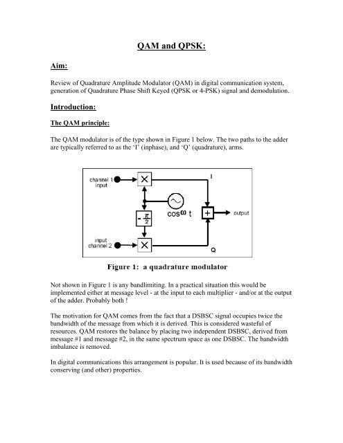
The <strong>QAM</strong> principle:<br />
The <strong>QAM</strong> modulator is of the type shown in Figure 1 below. The two paths to the adder<br />
are typically referred to as the ‘I’ (inphase), <strong>and</strong> ‘Q’ (quadrature), arms.<br />
Not shown in Figure 1 is any b<strong>and</strong>limiting. In a practical situation this would be<br />
implemented either at message level - at the input to each multiplier - <strong>and</strong>/or at the output<br />
of the adder. Probably both !<br />
The motivation for <strong>QAM</strong> comes from the fact that a DSBSC signal occupies twice the<br />
b<strong>and</strong>width of the message from which it is derived. This is considered wasteful of<br />
resources. <strong>QAM</strong> restores the balance by placing two independent DSBSC, derived from<br />
message #1 <strong>and</strong> message #2, in the same spectrum space as one DSBSC. The b<strong>and</strong>width<br />
imbalance is removed.<br />
In digital communications this arrangement is popular. It is used because of its b<strong>and</strong>width<br />
conserving (<strong>and</strong> other) properties.
It is not used for multiplexing two independent messages. Given an input binary sequence<br />
(message) at the rate of n bit/s, two sequences may be obtained by splitting the bit stream<br />
into two paths, each of n/2 bit/s. This is akin to a serial-to-parallel conversion.<br />
The two streams become the channel 1 <strong>and</strong> channel 2 messages of Figure 1.<br />
Because of the halved rate the bits in the I <strong>and</strong> Q paths are stretched to twice the input<br />
sequence bit clock period. The two messages are recombined at the receiver, which uses a<br />
<strong>QAM</strong>-type demodulator. The two bit streams would typically be b<strong>and</strong> limited <strong>and</strong>/or<br />
pulse shaped before reaching the modulator. A block diagram of such a system is shown<br />
in Figure 2 below.<br />
<strong>QAM</strong> becomes <strong>QPSK</strong>:<br />
The <strong>QAM</strong> modulator is so named because, in analog applications, the messages do in fact<br />
vary the amplitude of each of the DSBSC signals.<br />
In <strong>QPSK</strong> the same modulator is used, but with binary messages in both the I <strong>and</strong> Q<br />
channels, as describe above.<br />
Each message has only two levels, ±V volt. For a non-b<strong>and</strong>limited message this does not<br />
vary the amplitude of the output DSBSC. As the message changes polarity this is<br />
interpreted as a 180 0 phase shift, given to the DSBSC.<br />
Thus the signal in each arm is said to be undergoing a 1800 phase shift, or phase shift<br />
keying - or PSK. Because there are two PSK signals combined, in quadrature, the twochannel<br />
modulator gives rise to a quadrature phase shift keyed - <strong>QPSK</strong> - signal.
Constellation:<br />
Viewed as a phasor diagram (<strong>and</strong> for a non-b<strong>and</strong>limited message to each channel), the<br />
signal is seen to occupy any one of four point locations on the complex plane. These are<br />
at the corner of a square (a square lattice), at angles π/4, 3π/4, 5π/4 <strong>and</strong> 7π/4 to the real<br />
axis.<br />
M-PSK <strong>and</strong> M-<strong>QAM</strong>:<br />
The above has described digital-<strong>QAM</strong> or <strong>QPSK</strong>. This signal is also called 4-PSK or 4-<br />
<strong>QAM</strong>. More generally signals can be generated which are described as M-<strong>QAM</strong> or M-<br />
PSK. Here M = 2 L , where L = the number of levels in each of the I <strong>and</strong> Q arms. For the<br />
present experiment L = 2, <strong>and</strong> so M = 4. The ‘M’ defines the number of points in the<br />
signal constellation. For the cases M > 4 then M-PSK is not the same as M-<strong>QAM</strong>.<br />
The <strong>QAM</strong> Receiver:<br />
The <strong>QAM</strong> receiver follows the similar principles to those at the transmitter, <strong>and</strong> is<br />
illustrated in idealised from in the block diagram of Figure 3. It is idealised because it<br />
assumes the incoming signal has its two DSBSC precisely in phase quadrature. Thus only<br />
one phase adjustment is required.<br />
The parallel-to-serial converter block performs the following operations:<br />
1. regenerates the bit clock from the incoming data.<br />
2. regenerates a digital waveform from both the analog outputs of the I <strong>and</strong> Q arms.<br />
3. re-combines the I <strong>and</strong> Q signals, <strong>and</strong> outputs a serial data stream.
Not shown is the method of carrier acquisition. This ensures that the oscillator, which<br />
supplies the local carrier signal, is synchronized to the received (input) signal in both<br />
frequency <strong>and</strong> phase. In this experiment we will use a stole carrier to ensure that carrier<br />
signal in the transmitter <strong>and</strong> receiver are in synchronism with each other. (Please read<br />
about Costas Receiver to underst<strong>and</strong> more about carrier acquisition).<br />
In this experiment, two independent data sequences will be used at the input to the<br />
modulator, rather than having digital circuitry to split one data stream into two (the serialto-parallel<br />
converter). Two such independent data sequences, sharing a common bit clock<br />
(2.083 kHz), are available from a single SEQUENCE GENERATOR module. The data<br />
stream from which these two channels are considered to have been derived would have<br />
been at a rate of twice this - 4.167 kHz.<br />
Lowpass filter b<strong>and</strong>limiting <strong>and</strong> pulse shaping is not a subject of enquiry in this<br />
experiment. So a single b<strong>and</strong>pass filter at the ADDER (summer) output will suffice,<br />
providing it is of adequate b<strong>and</strong>width. A 100 kHz CHANNEL FILTERS module is<br />
acceptable (filter #3).<br />
Experimental Procedure:<br />
The <strong>QPSK</strong> transmitter:<br />
A model of the generator of Figure 1 is shown in Figure 4.<br />
The <strong>QAM</strong> modulator involves analog circuitry. Overload must be avoided, to prevent crosstalk<br />
between channels when they share a common path - the ADDER <strong>and</strong> output filter. In practice<br />
there would probably be a filter in the message path to each multiplier. Although these filters<br />
would be included for pulse shaping <strong>and</strong>/or b<strong>and</strong> limiting, a secondary purpose is to eliminate as<br />
many unwanted components at the multiplier (modulator) input as possible.<br />
T1 patch up the modulator according to Figure 4. Set the on-board switch SW1<br />
of the PHASE SHIFTER to HI. Select channel #3 of the 100 kHz<br />
CHANNEL FILTERS module (this is a b<strong>and</strong>pass filter of adequate b<strong>and</strong>width).
T2 there are no critical adjustments to be made. Set the signals from each input of the<br />
ADDER to be, say, 1 volt peak at the ADDER output.<br />
T3 for interest predict the waveforms (amplitude <strong>and</strong> shape) at all interfaces, then<br />
confirm by inspection.<br />
Constellation:<br />
You can display the four-point constellation for <strong>QPSK</strong>:<br />
T4 set the oscilloscope in X-Y mode. With no input, select equal gains per channel.<br />
Locate the ‘spot’ in the centre of the screen; then connect the two data streams entering<br />
the <strong>QAM</strong> to the scope X <strong>and</strong> Y inputs.<br />
The Demodulator:<br />
Modelling of the demodulator of Figure 3 is straightforward. But it consumes a lot of modules.<br />
Consequently only one of the two arms is shown in Figure 5.<br />
The PHASE SHIFTER can be used to select either channel from the <strong>QAM</strong> signal. If both<br />
channels required simultaneously, as in practice, then a second, identical demodulator must be<br />
provided.<br />
T5 patch up the single channel demodulator of Figure 5, including the z-mod facility of<br />
the DECISION MAKER.<br />
T6 while watching the ‘I’ channel at the transmitter, use the PHASE SHIFTER to match<br />
the demodulator output with it.<br />
T7 while watching the ‘Q’ channel at the transmitter, use the PHASE SHIFTER to match<br />
the demodulator output with it.
Tutorial Questions:<br />
1) Explain how a <strong>QAM</strong> system conserves b<strong>and</strong>width.<br />
2) The modulator used the quadrature 100 kHz outputs from the MASTER<br />
SIGNALS module. Did it matter if these were not precisely in quadrature ?<br />
Explain.<br />
3) Name one advantage of making the bit rate a sub-multiple of the carrier<br />
frequency.<br />
4) Why is there a need to eliminate as many unwanted components as possible<br />
into the modulator ?