Kmirror controller electronics.pdf - JACH
Kmirror controller electronics.pdf - JACH
Kmirror controller electronics.pdf - JACH

You also want an ePaper? Increase the reach of your titles
YUMPU automatically turns print PDFs into web optimized ePapers that Google loves.
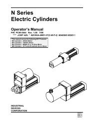
K Mirror for HARP-B<br />
K-Mirror Controller<br />
v2 - Feb 2012<br />
Compiled by TCC<br />
INDEX<br />
JacDocs Index 2012<br />
Photos<br />
Extract from ‘K-Mirror for HARP-B Operations Manual’<br />
Wiring Diagram<br />
Parts List<br />
Spares List<br />
K-Mirror Drive Rack S648 Instruction Manual - Cortex<br />
Data Sheets -<br />
Motion Controller - Galil DMC-1412<br />
PSU – Artesyn NFS110-7602P<br />
Incremental Encoder (2500 pulse/rev) – Hengstler RI 58-0/2500AS.41RB<br />
Limit/Home Switch – Burgess V3S Microswitch<br />
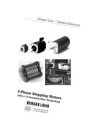
5-Phase Stepper Motor Drive Card – Cortex D450-B157 (Berger-Lahr D450<br />
equivalent)<br />
5-Phase Stepper Motor - Sig Positic (Berger-Lahr) VRDM 568/50 (1ph 1.5A, 1.6<br />
ohm)
K-Mirror JacDocs Index 2012
PHOTOS<br />
Controller
Drive Assembly<br />
Micro switches L-R :- -Ve Limit/ Home/ +Ve Limit<br />
Mirror in +Ve Limit
Extract from ‘K-Mirror for HARP-B Operations Manual’<br />
Mechanical stops are set at +/- 60º<br />
Limit switches act at +/- 58.7º<br />
EPICS control limits range to +/- 110º on sky (+/- 55º rotation)<br />
TCS limits demand to +/- 109.5º on sky<br />
2.5 deg/sec = 1700 motor steps/sec<br />
5 deg/sec = 3400 motor steps/sec<br />
Motor VRDM568/50 half step mode (1000 steps/rev)<br />
Motor Encoder 2500 lines/rev (10,000 encoder steps/rev)<br />
Intermediate gear (anti-backlash) 1:1, 54 teeth, metric module 1<br />
Worm metric module 2, (Tooth Pitch 6.283 mm)<br />
Wheel PCD 490 mm<br />
Worm/Wheel gear ratio 245:1<br />
K-Mirror rotation 1.469 deg/motor rev
End-stop pins on wormshaft set to lock-up at +/-60 degrees<br />
Home switch activated for ~1300 motor steps<br />
(1050 – 1360 motor steps, depending on mirco-switch positioning)<br />
Hysteresis ~32 steps
HARP- B<br />
HARP-B Project Document<br />
K Mirror for HARP-B : Operations Manual<br />
Ref.: HAR_KMI_DOC_0001<br />
Version: 1.1<br />
Page 25 of 64<br />
Date: 13.Dec.01<br />
Author: Ian Pain<br />
1.8 Control & Electronics<br />
1.8.1 Description<br />
The K-Mirror is driven by a double-ended Berger-Lahr 5-phase stepper motor. The motor is<br />
controlled by a drive box, which will be housed within the Receiver Cabin. Micro-switches<br />
are used to let the <strong>controller</strong> know if the mirror has hit a limit and to home the mirror. An<br />
encoder is also be used to verify the mirror has moved to the correct position. Cables run<br />
from the box to a connector panel close to the motor. Connections for the motor, Encoder<br />
and switches are made via this panel.<br />
RS232<br />
115V / 240V<br />
Interlock<br />
Switch<br />
Encoder I/P<br />
Power supply<br />
Switch I/Ps<br />
Galil 1412<br />
Motor<br />
Controller<br />
Step<br />
Dir<br />
De-pwr<br />
Motor<br />
Drive<br />
Motor<br />
Figure 16 : Motor Drive Box, schematic<br />
The motor drive box houses the motor <strong>controller</strong>, drive card and power supplies. A lockable<br />
mains switch is used to apply power to the box, thus enabling it to be locked off when work<br />
is being carried out on the mirror preventing it from being switched on.<br />
- 25 -
HARP- B<br />
HARP-B Project Document<br />
K Mirror for HARP-B : Operations Manual<br />
Ref.: HAR_KMI_DOC_0001<br />
Version: 1.1<br />
Page 26 of 64<br />
Date: 13.Dec.01<br />
Author: Ian Pain<br />
Figure 17 Motor Drive Box, front<br />
Figure 18 Motor Drive Box, rear<br />
- 26 -
HARP- B<br />
HARP-B Project Document<br />
K Mirror for HARP-B : Operations Manual<br />
Ref.: HAR_KMI_DOC_0001<br />
Version: 1.1<br />
Page 27 of 64<br />
Date: 13.Dec.01<br />
Author: Ian Pain<br />
1.8.2 Motor Controller<br />
The Galil 1412 motor <strong>controller</strong> is used to control the motion of the K-mirror. This is a<br />
single axis stand-alone <strong>controller</strong>, which accepts commands via an RS 232 port. The<br />
<strong>controller</strong> will send Direction and Step signals to the drive card. One of the digital outputs is<br />
also used to send a de-power signal to the drive card. The <strong>controller</strong> accepts inputs from the<br />
limit and home switches and the encoder. Input from the limit switches will cause the<br />
<strong>controller</strong> to stop the motor; it will then only allow the motor to be driven in the opposite<br />
direction away from the limit switch. The motor will only stop in the direction it is moving<br />
when the respective switch is hit. When moving forward it is only the forward limit switch<br />
that will stop motion.<br />
The <strong>controller</strong> will only stop the motor when the home switch is activated if it is looking for<br />
its home position through software control. The limit switches however act independently<br />
from the software.<br />
The commands for the <strong>controller</strong> are two letter, English like ASCII commands. For example<br />
“BG” command begins motion and “SP 2000” sets the speed at 2000.<br />
1.8.3 Motor Drive Card<br />
The Motor drive card has been designed by Cortex Controllers for use with the Berger-Lahr<br />
5-phase stepper motors. The card accepts TTL inputs from the <strong>controller</strong> to give direction<br />
and the step. It in turn produces the 5 phases to drive the motor. The De-power input<br />
removes power from all of the motor windings when it is active. This prevents the motor<br />
from heating or produce any noise when it is inactive. The card can be switched between<br />
full and half step modes and is set for half step operation.<br />
1.8.4 Encoder<br />
The incremental shaft encoder, see Figure 9 , Figure 25 will act as a check to see if the<br />
required position has been obtained, an error can be flagged if it does not match the<br />
requested move. It can also be used to create an error if the motor does not move. If a<br />
request has been sent to the motor but the software does not see the encoder change then an<br />
error can be flagged. The encoder phases have been swapped round to enable the increments<br />
to be in the same direction as the <strong>controller</strong>s step counts. Phase A+ on the encoder is<br />
connected to Phase B+ at the <strong>controller</strong>. Similarly A- to B-, B+ to A+ and B- to A-. There<br />
are ten encoder pulses for every step.<br />
1.8.5 Safety<br />
An emergency stop push button (ESPB) will remove power from the motor when pressed<br />
stopping the motor. Power will however remain on the motor <strong>controller</strong>. When the ESPB is<br />
pressed and power removed from the motor, the encoder continues to read if the system is<br />
moved by hand. However as this is an open loop system and the <strong>controller</strong> just uses the step<br />
count for its position it will think it is still at the position where it stopped. It may be<br />
possible for the software to allow the user to enter a new step count to match the encoder<br />
reading where the step count should be encoder reading / 10 provided they are both zeroed at<br />
the index position.<br />
The drive box is supplied with a lockable mains switch. This will allow any lock out, tag out<br />
procedures in place to be followed, locking off the power to the motor when any work is<br />
being carried out on or near when movement of the motor is unsafe.<br />
- 27 -
1 - FTP FEB 2001<br />
Encoder pin signals<br />
different, sig +/- wires may<br />
not be twisted together!<br />
No connection for Screen<br />
microswitches wired with<br />
+5v & gnd
2 - Doc CD DEC 2001<br />
Encoder pin signals<br />
different, sig +/- wires may<br />
not be twisted together!<br />
microswitches wired with<br />
+5v & gnd
3 - Modified JUN2006<br />
Encoder pin signals in<br />
sequence<br />
microswitches wired with<br />
filter on NC to gnd<br />
Details for Berger-Lahr card
1 - FTP FEB 2001<br />
Encoder pin signals in<br />
sequence<br />
Encoder color code for<br />
PTFE wire<br />
microswitches wired with<br />
+5v & gnd
2 - Doc CD DEC 2001<br />
Encoder pin signals<br />
different, sig +/- wires may<br />
not be twisted together!<br />
Encoder wired reverse<br />
phase<br />
microswitches wired with<br />
+5v & gnd
3 - Modified JUN2006<br />
Encoder pin signals in<br />
sequence<br />
microswitches wired with<br />
only gnd
Wiring<br />
Stepper Motor Connector<br />
Communication
Parts list for K-Mirror Motor drive<br />
Part Part Number Supplier Order number Price Quantity Total Delivery<br />
Motor V564/50 Sig Positec 12170 0151 00 £289.32 2 £579 4-6 weeks<br />
Encoder RI58-0 5vdc RS 260-3897 £117.00 1 £117 Next day<br />
Micro switches V3S RS 317-998 £8.10 6 £49 Next day<br />
Emegency stop RS 139-215 £27.72 1 £28 Next day<br />
Motor Drive Box Cortex Controllers £1,900.00 1 £1,900 6 weeks<br />
Motor Controller (Spare) DMC-1412 Naples Coombe £510.00 1 £510<br />
Drive card (Spare) Cortex Controllers £200.00 1 £200 6 weeks<br />
Test Software ActiveX Naples Coombe £500.00 1 £500<br />
Connector 97-3106A20-27P Electrospeed 7777-17826B £31.73 1 £32 1 week<br />
MS3116F14-12S Electrospeed 7777-17602B £27.05 1 £27 1 week<br />
MS3110F14-12P Electrospeed 7777-17764J £20.48 1 £20 1 week<br />
MS3116F14-15S Electrospeed 7777-17604J £25.81 1 £26 1 week<br />
MS3110F14-15P Electrospeed 7777-17766E £23.63 1 £24 1 week<br />
MS3116F12-10S Electrospeed 7777-17598L £28.45 1 £28 1 week<br />
MS3110F12-10P Electrospeed 7777-17760F £25.93 1 £26 1 week<br />
FGG 1B 2P (Lemo) Electrospeed 275-56104K £11.74 1 £12 1 week<br />
15 Way D-Type Plug Electrospeed 17-906640E £3.78 1 £4 1 week<br />
9 Way D-Type Plug Electrospeed 17-906639D £2.92 1 £3 1 week<br />
Cable Belden 9505 (30m) Arrow 027547G £57.15 1 £57 1 week<br />
Belden 9539 (30m) Arrow 075801D £51.20 1 £51 1 week<br />
Belden 9533 Arrow 009396D £26.54 1 £27 1 week<br />
Total £4,218
HARP K-Mirror Spares list: dated 27.MAY.02 v 1.1<br />
SPARES<br />
Part Part No. Quantity USED on Supplier<br />
HPC ABSI 54 ...54 teeth 1.0 Mod<br />
Gear (anti backlash)<br />
STS 303S22 1 HARP-021-003 HPC<br />
SPUR GEAR<br />
HPC G1 54 ... 54 TEETH 1.0<br />
MOD STS 303S22 1 HARP-021-003 HPC<br />
Bearing taper roller : 30302 SKF_30302 2 HARP-021-003 BSL<br />
ANG CONTACT Bearing 7301 7301_ANG_CONT 2 HARP-021-003 BSL<br />
STEPPER MOTOR VRDM 568/50 lam VRDM 568/50 lam 1 HARP-021-003 SIG POSITEC<br />
SHAFT ENCODER 256-483 256-484 1 HARP-021-003 RS<br />
COUPLING RS_3 25_8066 1 HARP-021-003 RS<br />
LOCK NUT KMT2 M15X1 KMT2 M15X2 1 HARP-021-003 BSL<br />
LOCKNUT KMT1 M12X1 KMT1 M12X2 1 HARP-021-003 BSL<br />
LOCK NUT KMT 0 1 HARP-021-003 BSL<br />
OILITE BUSH QFM12-16 FLANGED QFM12-16 FLANGED 4 HARP-021-003 BSL<br />
FELT SHEET 2mm<br />
500mm x 500mm HARP-021-003<br />
OILSEAL RST 25X42X7 1 HARP-021-003 BSL<br />
SPRING D22010 1 HARP-021-004 SPRINGMASTER<br />
SPIROL PIN DIA 3.0 10<br />
SPIROL INDUSTRIES<br />
LTD.<br />
BRAKE PAD 3 HARP-021-003<br />
M10 EYEBOLT 1 HARP-021-003<br />
M8 EYEBOLT 4 HARP-021-004<br />
DRIVE CARD 1<br />
GALIL BOARD GALIL DMC 1412 1<br />
SPECIAL TOOLS<br />
Part Quantity USED on Supplier Notes<br />
C-SPANNER FOR BEARING NUT<br />
TIGHTENING 1 SKF<br />
HANDLING TROLLEY EXP-021-008 1 EXPRESS Engineering<br />
ALIGNMENT COLLET N/A 1 K-MIRROR ALIGNMENT UK ATC<br />
ALIGNMENT JIG HARP-50A00A 1 K-MIRROR ALIGNMENT UK ATC<br />
CMM ALIGNMENT MOUNT EXP-021-007 NIL EXPRESS Engineering RETAINED AT ATC<br />
MIRROR DUMMY HARP-021-002-001 1 UK ATC<br />
MIRROR DUMMY HARP-021-002-002 1 UK ATC<br />
MIRROR DUMMY HARP-021-002-003 1 UK ATC<br />
K-MIRROR STATIC<br />
MOUNT/TELESCOPE SIMULATOR EXP-021-006 NIL EXPRESS Engineering RETAINED AT ATC<br />
(eg provided where prove out piece<br />
non-essential spares<br />
available etc)<br />
Part Quantity USED on Supplier Notes<br />
Mirror mount 1<br />
Mirror c-shaped shims EXP-021-004-018 NIL HARP-021-004<br />
Sized, stamped and marked as<br />
EXPRESS Engineering replacements for O shaped shims<br />
Gear sector blank NIL HARP-021-004 EXPRESS Engineering unmachined brass gear ring<br />
misc fasteners<br />
dowel pins<br />
cable<br />
short test cable<br />
OBSOLETE MIRROR CLAMPS EXP-021-002-001 4 EXPRESS Engineering SUPPLIED 'IN CASE USEFUL'<br />
OBSOLETE MIRROR CLAMPS EXP-021-002-002 2 EXPRESS Engineering SUPPLIED 'IN CASE USEFUL'<br />
OBSOLETE MIRROR CLAMPS EXP-021-002-003 2 EXPRESS Engineering SUPPLIED 'IN CASE USEFUL'<br />
OBSOLETE ALIGNMENT COLLET 1 EXPRESS Engineering SUPPLIED 'IN CASE USEFUL'<br />
CONNECTORS, AMPEHNOL<br />
1 each type
HARP_B Project Document<br />
HARP K- MIRROR<br />
Ref:- HAR -KMI-DOC-CORTEX-S648
BERGER-LAHR D450 STEPPER DRIVE CARD
BERGER-LAHR D450 STEPPER DRIVE CARD<br />
Stepper Motor<br />
VRDM566/50<br />
VRDM568/50
Data Sheets -<br />
Motion Controller - Galil DMC-1412<br />
PSU – Artesyn NFS110-7602P<br />
Incremental Encoder (2500 pulse/rev) – Hengstler RI 58-0/2500AS.41RB<br />
Limit/Home Switch – Burgess V3S Microswitch<br />
5-Phase Stepper Motor Drive Card – Cortex D450-B157 (Berger-Lahr D450<br />
equivalent)<br />
5-Phase Stepper Motor - Sig Positic (Berger-Lahr) VRDM 568/50 (1ph 1.5A, 1.6<br />
ohm)
FEATURES<br />
MOTION<br />
■ Modes of motion include jogging, point-to-point positioning, contouring, electronic gearing and ECAM<br />
■ Dual-loop control and backlash compensation<br />
■ Servo loop update rates as low as 375 microseconds—faster rates<br />
available as an option<br />
■ Encoder frequencies up to 8 MHz; Step motors up to 2 MHz<br />
■ Software PID control with velocity and acceleration feedforward,<br />
offsets and integration limits<br />
INPUTS/OUTPUTS<br />
■ Provides main and auxiliary encoder input<br />
■ 7 uncommitted TTL inputs and 3 TTL outputs<br />
■ Forward and Reverse limits and home input for each axis<br />
■ High-speed position capture<br />
PROGRAMMING<br />
■ On-board, non-volatile memory for storing<br />
parameters<br />
■ DMC-1412: On-board memory for storing<br />
application programs, variables and<br />
arrays<br />
■ Programmable event triggers including<br />
At Time, At Position, At Input, At Speed<br />
■ Multitasking for simultaneous execution of<br />
two applications programs<br />
■ Intuitive, English-like command language<br />
with over 200 commands directly executable<br />
by <strong>controller</strong><br />
■ Extensive DLLs and documentation for C/C++<br />
programmers<br />
■ Software tools for automatic servo tuning and analysis; ActiveX controls<br />
for Visual Basic<br />
■ Drivers for QNX, DOS, Windows 3.1, 95, 98, 2000, NT and CE<br />
FORMATS<br />
■ 1 1 / 2 axes<br />
MOTION CONTROLLERS<br />
■ ISA, PC/104, and RS232*<br />
■ DMC-1412 also available as packaged unit with internal power supply<br />
■ DMC-1414 packaged <strong>controller</strong> includes an internal servo amplifier and integrated screw terminals<br />
■ Controls step motors and servo motors<br />
■ On-board sinusoidal commutation for brushless motors available on DMC-1410 and DMC-1412<br />
ECONO SERIES<br />
DMC-1410, 1411, 1412, 1414<br />
DMC-1410<br />
ISA Bus<br />
DMC-1412<br />
RS232<br />
DMC-1411<br />
PC/104<br />
* Ethernet available on DMC-1415, DMC-1416, and DMC-1425 which are described in another section.<br />
www.galilmc.com • Galil Motion Control, Inc. • 33
MOTION CONTROLLERS<br />
ECONO SERIES<br />
DMC-1410, 1411, 1412, 1414<br />
DESCRIPTION<br />
Galil’s DMC-1400 Econo Series of single-axis <strong>controller</strong>s<br />
have proven to be the best choice for those requiring<br />
minimum cost and space. Not only are these <strong>controller</strong>s<br />
roughly half the size of multiaxis <strong>controller</strong>s—they are<br />
also half the price. Even so, performance is not sacrificed<br />
in the least. In fact, the Econo Series handle the most<br />
demanding applications with such features as an extra<br />
encoder input which is ideal for electronic gearing, program<br />
memory with multitasking, uncommitted I/O for<br />
synchronizing motion with external events, and userselectable<br />
stepper or servo motor control.<br />
Best of all, the Econo Series remain—like all Galil products—very<br />
easy to use. For example, upgrading is painless<br />
since the two-letter commands maintain the same format<br />
as prior generations. System setup and programming is easier<br />
than ever with such enhanced software tools as WSDK<br />
FUNCTIONAL ELEMENTS<br />
RS232<br />
for tuning and analysis, ActiveX Tool Kit for interface to<br />
Visual Basic, and a C-Programmers Tool Kit. Also, software<br />
is compatible with DOS, QNX, Windows 3.1, Windows<br />
95, Windows NT, Windows 98, and Windows 2000.<br />
Various options are available for the DMC-1400 series<br />
including the DMC-1410 ISA <strong>controller</strong>, DMC-1411<br />
PC/104 <strong>controller</strong>, and DMC-1412 stand-alone <strong>controller</strong><br />
with RS232. The DMC-1414 includes<br />
an integrated PWM amplifier for<br />
driving brush-type motors.<br />
Note: The Ethernet interface<br />
is included with the<br />
DMC-1415,<br />
DMC-1416,<br />
and DMC-1425<br />
Econo <strong>controller</strong>s<br />
which are described<br />
in another section.<br />
DMC-1412<br />
Stand-alone Box<br />
WATCHDOG TIMER<br />
DUAL UART<br />
FORWARD AND REVERSE LIMITS AND HOME INPUT<br />
DMC-1412<br />
DMC-1410/1411<br />
HIGH-SPEED<br />
COMMUNICATION<br />
INTERFACE<br />
256 BYTE FIFO<br />
68331<br />
MICROCOMPUTER<br />
WITH<br />
32 K RAM<br />
64 K EPROM<br />
256 K EEPROM<br />
HIGH-SPEED<br />
MOTOR/ ENCODER<br />
INTERFACE<br />
MAIN ENCODER<br />
AUXILIARY ENCODER<br />
±10 VOLT OUTPUT FOR SERVO MOTORS<br />
PULSE/DIRECTION OUTPUT FOR STEP MOTORS<br />
I/O INTERFACE<br />
PC BUS<br />
I/O ADDRESS<br />
HIGH-SPEED LATCH 7 PROGRAMMABLE 3 PROGRAMMABLE<br />
INPUTS<br />
OUTPUTS<br />
INTERRUPTS<br />
34 • Galil Motion Control, Inc. • www.galilmc.com
MOTION CONTROLLERS<br />
ECONO SERIES<br />
DMC-1410, 1411, 1412, 1414<br />
COMMAND LANGUAGE<br />
Galil’s command language is comprised of intuitive, twoletter,<br />
English-like ASCII commands designed to make<br />
programming as quick and easy as possible. For example,<br />
the “BG” command begins motion while the “SP 2000”<br />
command sets the speed of the X-axis as “2000.” Commands<br />
are included for system set-up, tuning, prescribing motion,<br />
error handling and applications programming. A complete<br />
set of commands is described in the following table.<br />
Custom commands can be created upon request.<br />
PID COMPENSATION<br />
Galil <strong>controller</strong>s provide a compensation function which<br />
includes a PID (Proportional-Integral-Derivative) filter.<br />
The compensation also includes velocity and acceleration<br />
feedforward. All filter parameters are adjustable, allowing<br />
servo system tuning for best performance. Dual loop control<br />
is provided for reducing the effect of backlash.<br />
PID Block Diagram<br />
S<br />
S<br />
K p<br />
FA<br />
FV<br />
Σ<br />
OF<br />
APPLICATIONS PROGRAMMING<br />
One of the more powerful features of all Galil <strong>controller</strong>s is<br />
their ability to store and execute complex application programs<br />
designed by the user. Such applications programs can<br />
be downloaded directly to the <strong>controller</strong> and executed without<br />
host intervention. The benefit of this is the freeing of<br />
the PC for system-level tasks. In fact, Galil <strong>controller</strong>s permit<br />
multitasking, which allows up to two programs to execute<br />
simultaneously. Also, special commands are available<br />
for application programming including event triggers, conditional<br />
jumps, subroutines, symbolic variables and arrays.<br />
Example—Change Speed on Input<br />
Move the x-axis forward a distance of 20000 counts at an<br />
initial speed of 50000 counts/sec and with an acceleration<br />
and deceleration of 1000000 counts/sec 2 . As soon as the<br />
motor activates the sensor connected to input 1, reduce the<br />
speed to 25000 counts/sec.<br />
PROGRAM<br />
INTERPRETATION<br />
#A Label<br />
PR 20000 Distance<br />
SP 50000 Initial speed<br />
AC 1000000 Acceleration rate<br />
DC 1000000 Deceleration rate<br />
BGX<br />
Start the motion<br />
AI 1<br />
Wait for the sensor input<br />
SP 25000 Reduce the speed<br />
EN<br />
End program<br />
R<br />
+<br />
–<br />
Σ<br />
K d• s<br />
Σ<br />
Σ<br />
Σ<br />
TL<br />
OUT<br />
VELOCITY<br />
K i<br />
s<br />
IL<br />
TIME<br />
INPUT 1<br />
www.galilmc.com • Galil Motion Control, Inc. • 35
MOTION CONTROLLERS<br />
ECONO SERIES<br />
DMC-1410, 1411, 1412, 1414<br />
MODES OF MOTION<br />
Point-to-Point Motion<br />
The Point-to-Point Motion mode allows the target position<br />
(PA or PR), slew speed (SP), acceleration (AC) and<br />
deceleration (DC) to be specified. Upon begin (BG), the<br />
<strong>controller</strong> generates a trapezoidal velocity profile where<br />
the speed and acceleration can be changed anytime during<br />
motion. For applications that require smooth motion<br />
without abrupt velocity transitions, a motion smoothing<br />
function (IT) is provided. The position (TP) and position<br />
error (TE) may be interrogated at anytime.<br />
Example—Jogging<br />
COMMAND<br />
JG 20000<br />
AC 1000000<br />
DC 1000000<br />
BG<br />
WT 5000<br />
JG 30000<br />
WT10000<br />
ST<br />
INTERPRETATION<br />
Specify jog speed and direction<br />
Specify acceleration<br />
Specify deceleration<br />
Begin motion<br />
Wait 5 seconds<br />
Increase X speed<br />
Wait 10 seconds<br />
Stop motion<br />
Example—Point-to-Point Motion<br />
COMMAND<br />
AC 1000000<br />
DC 1000000<br />
SP 20000<br />
PR 40000<br />
BG<br />
INTERPRETATION<br />
Specify acceleration rate<br />
Specify deceleration rate<br />
Specify slew speed<br />
Specify distance<br />
Begin motion<br />
Jogging<br />
In the jog mode, each axis is given a jog speed and direction<br />
(JG), acceleration (AC), and deceleration (DC). Upon begin<br />
(BG), the <strong>controller</strong> ramps up to the jog speed at the prescribed<br />
acceleration following a trapezoidal profile. A<br />
smoothing function (IT) is provided to smooth abrupt<br />
velocity transitions. The stop command (ST) stops the<br />
motion at the prescribed deceleration rate. The jog speed<br />
and direction, acceleration and deceleration may be changed<br />
at anytime during motion. The average speed can be interrogated<br />
at any time using the Tell Velocity (TV) command.<br />
Electronic Gearing<br />
The electronic gearing mode makes it easy for Galil <strong>controller</strong>s<br />
to simulate the motion of mechanical gears electronically.<br />
A slave axis can be geared to an external master<br />
at a prescribed gear ratio defined by the GR command.<br />
The gear ratio can be changed on-the-fly.<br />
Electronic CAM<br />
In the electronic CAM mode, the motor’s position can<br />
be linked to an external motor position, allowing simulation<br />
of a mechanical CAM. The CAM functions are specified<br />
by a table that allows complex profiles with varying<br />
gear ratios to be prescribed. The follower axis may be<br />
engaged or disengaged independently at specific points<br />
along a CAM cycle. This allows selecting the engagement<br />
and disengagement points as those where the speed<br />
change of the follower is minimal.<br />
The electronic CAM is an ideal mode for periodic<br />
operation, especially those requiring varying gear ratio<br />
along the motion cycle. Such applications include flying<br />
shears, rotating knives, and packaging systems.<br />
Contouring<br />
The contouring mode (CM) is extremely flexible and allows<br />
any arbitrary profile to be prescribed. Here, the user bypasses<br />
the <strong>controller</strong> profiler and inputs the position versus time<br />
trajectory directly. The trajectory is described as the position<br />
increment (CD) over a defined time period (DT). The <strong>controller</strong><br />
performs linear interpolation between prescribed<br />
points. The contour mode is useful for following complex,<br />
computer-generated paths or for “teaching” position paths.<br />
An automatic data-recording feature allows the <strong>controller</strong> to<br />
“learn” a path and then follow it in the contour mode.<br />
36 • Galil Motion Control, Inc. • www.galilmc.com
MOTION CONTROLLERS<br />
ECONO SERIES<br />
DMC-1410, 1411, 1412, 1414<br />
Error Handling<br />
Dedicated I/O is provided for safety controls: forward<br />
and reverse limit inputs, amplifier enable output, abort<br />
input and error output. In addition, the <strong>controller</strong> provides<br />
safety functions in software: upper and lower software<br />
travel limits, error limits, and automatic shut-off on<br />
excess error. In addition, program interrupts are provided<br />
for error and limit conditions. The program interrupts<br />
cause the program sequencer to automatically branch to<br />
an error handling subroutine. The error handling subroutine<br />
can be customized by the user to provide flexibility<br />
and system protection.<br />
Dual-Loop<br />
The dual-loop (DV) feature enables the <strong>controller</strong> to<br />
compensate for mechanical backlash. Typically, dual-loop<br />
systems use a rotary encoder on the motor and a linear<br />
encoder on the load (Galil <strong>controller</strong>s accept inputs from<br />
two encoders per axis as a standard feature). Dual-loop<br />
control changes the standard PID control and closes the<br />
position loop with the load encoder (“PI”) and derives<br />
the damping terms (“D”) from the motor encoder. This<br />
method provides smooth and accurate control along the<br />
motion path regardless of backlash.<br />
Dual-loop Block Diagram<br />
R<br />
OTHER FEATURES<br />
∑<br />
+<br />
-<br />
PI<br />
∑<br />
+<br />
-<br />
D<br />
AMP/MOTOR<br />
MOTOR<br />
ENCODER<br />
LOAD SENSOR<br />
BACKLASH<br />
LOAD<br />
Sinusoidal Commutation<br />
Sinusoidal commutation assures smooth motion and<br />
reduces torque ripple when using brushless motors. The<br />
DMC-1410, DMC-1412, and DMC-1414 stand-alone <strong>controller</strong><br />
includes a sinusoidal commutation feature that<br />
allows designers to use lower-cost servo drives. Sinusoidally<br />
commutated motion requires two DAC outputs that are<br />
phase shifted by 120º. The third commutation signal is<br />
generated by the servo amplifier. The commutation can be<br />
initialized with or without hall sensors.<br />
General Inputs and Outputs<br />
The <strong>controller</strong> provides general purpose I/O for direct<br />
interface with PLC’s, sensors, switches, and other devices.<br />
In addition, there are inputs and outputs dedicated for<br />
special features.<br />
Homing<br />
The <strong>controller</strong> provides a home input and an encoder index<br />
input. These inputs combined with Galil’s built-in homing<br />
commands, allow for quick and accurate homing.<br />
High-speed Position Capture<br />
Galil <strong>controller</strong>s provide a high-speed position capture<br />
input for each axis. This feature latches the exact position<br />
within .1 microsecond of the occurrence of an input.<br />
Position capture is crucial for applications requiring precise<br />
synchronization of position to external events such as<br />
coordinate measurement machines.<br />
Customization<br />
Contact Galil for any special hardware or software feature<br />
you need. We can create a custom mode of motion exactly<br />
to your specifications, design a circuit board with a special<br />
connector or design to fit space constraints. An experienced<br />
application engineer will help you develop a specification<br />
and provide you with a quotation for custom services.<br />
www.galilmc.com • Galil Motion Control, Inc. • 37
MOTION CONTROLLERS<br />
ECONO SERIES<br />
DMC-1410, 1411, 1412, 1414<br />
SPECIFICATIONS<br />
SYSTEM PROCESSOR<br />
■ Motorola 32-bit microcomputer<br />
COMMUNICATIONS INTERFACE<br />
■ DMC-1410: ISA with bi-directional, high speed FIFO buffer<br />
■ DMC-1411: PC/104 with bi-directional, high speed FIFO<br />
buffer<br />
■ DMC-1412: (2) daisy-chainable RS232 ports up to 38.4K baud<br />
■ DMC-1414: (2) daisy-chainable RS232/RS422 ports up to<br />
38.4K baud; RS485 option<br />
MODES OF MOTION:<br />
■ Point-to-point positioning<br />
■ Jogging<br />
■ Electronic Gearing<br />
■ Electronic Cam<br />
■ Contouring<br />
MEMORY<br />
■ Program memory size—250 lines × 40 characters<br />
■ 126 variables<br />
■ 1000 array elements in up to 6 arrays<br />
FILTER<br />
■ PID (proportional-integral-derivative) with velocity and<br />
acceleration feedforward<br />
■ Dual-loop control for backlash compensation<br />
■ Velocity smoothing to minimize jerk<br />
■ Integration limits<br />
■ Torque limits<br />
■ Offset adjustment<br />
KINEMATIC RANGES<br />
■ Position: 32 bit (±2.15 billion counts per move; automatic<br />
rollover; no limit in jog or vector modes)<br />
■ Velocity: Up to 8 million counts/sec for servo motors<br />
■ Acceleration: Up to 67 million counts/sec 2<br />
UNCOMMITTED DIGITAL I/O<br />
■ 7 TTL inputs<br />
■ 3 TTL outputs<br />
DEDICATED I/O<br />
■ Main encoder inputs—Channel A, A-, B,B-,I, I- (±12 V or TTL)<br />
■ Auxiliary encoder—Channel A, A-, B, B-<br />
■ Forward and reverse limit inputs<br />
■ Home input<br />
■ High-speed position latch input<br />
■ Analog motor command output with 16-bit DAC resolution<br />
■ Pulse and direction output for step motors<br />
■ Amplifier enable output<br />
■ Error output<br />
MINIMUM SERVO LOOP UPDATE RATE<br />
■ 375 microsecond<br />
MAXIMUM ENCODER FEEDBACK RATE<br />
■ 8 MHz<br />
MAXIMUM STEPPER RATE<br />
■ 2 MHz (Full, half or microstep)<br />
POWER REQUIREMENTS<br />
■ DMC-1410, DMC-1411, DMC-1412, DMC-1415 card:<br />
+5V 400mA<br />
-12V 40mA<br />
+12V 40mA<br />
■ DMC-1412 Box: plugs into 90–260 VAC<br />
■ DMC-1414: requires single 20–60 V DC supply<br />
ENVIRONMENTAL<br />
■ Operating temperature: 0–70º C<br />
■ Humidity: 20-95% RH, non-condensing<br />
MECHANICAL<br />
■ DMC-1410: 7" ISA<br />
■ DMC-1411: 4.4" × 4.15"<br />
■ DMC-1412: 6.4" × 4.7"<br />
■ DMC-1412 Box-level: 5.1" × 3.0" × 6.8"<br />
■ DMC-1414 Box-level: 6" × 8.5" × 2.9"<br />
HIGH SPEED POSITION LATCH<br />
■ Latches within .1 microsecond<br />
38 • Galil Motion Control, Inc. • www.galilmc.com
MOTION CONTROLLERS<br />
ECONO SERIES<br />
DMC-1410, 1411, 1412, 1414<br />
INSTRUCTION SET<br />
MOTION<br />
AB Abort motion<br />
AC Acceleration<br />
BG Begin motion<br />
CD Contour data<br />
CM Contour mode<br />
DC Deceleration<br />
DT Contour time interval<br />
EB Enable cam mode<br />
EG Start cam motion<br />
EM Modulus for cam<br />
EP Master counts per table entry<br />
EQ Stop cam motion<br />
ET Cam table entry<br />
FE Find edge<br />
FI Find index<br />
GR Gear ratio<br />
HM Home<br />
IP Increment position<br />
IT Smoothing time constant–independent<br />
JG Jog mode<br />
KS Stepper smoothing<br />
PA Position absolute<br />
PR Position relative<br />
SP Speed<br />
ST Stop<br />
PROGRAM FLOW<br />
AD Wait for specified distance<br />
AI Wait for specified input<br />
AM Wait for motion complete<br />
AP Wait for absolute position<br />
AR Wait for relative distance<br />
AS Wait for “At Speed”<br />
AT Wait for elapsed time<br />
EN End program<br />
HX Halt task<br />
IN Input variable<br />
II Input interrupt<br />
JP Jump to program location<br />
JS Jump to subroutine<br />
MG Message<br />
MC Wait for “In Position”<br />
MF Forward motion past position<br />
MR Reverse motion past position<br />
NO No operation<br />
RE Return from error subroutine<br />
RI Return from interrupt<br />
WC Wait for contour data<br />
WT Wait for elapsed time<br />
XQ Execute program<br />
ZS Zero subroutine stack<br />
TW Timeout for “In Position”<br />
CONFIGURATION<br />
AL Arm latch<br />
BN Save parameters in EEPROM<br />
BP Burn program (1412, 1414)<br />
BV Burn variables and array (1412, 1414)<br />
CB Clear output bit<br />
CC Configure 2nd RS232 port (1412, 1414)<br />
CE Configure encoder type<br />
CN Configure switches<br />
DA Deallocate arrays<br />
DE Define dual encoder position<br />
DL Download program<br />
DM Dimension arrays<br />
DP Define position<br />
ED Edit mode<br />
EI Enable ISA interrupts (1410, 1411)<br />
EO Echo off<br />
LS List program<br />
MO Motor off<br />
MT Motor type<br />
OB Define output bit<br />
OP Output port<br />
PF Position format<br />
QD Download array<br />
QU Upload array<br />
RA Record array<br />
RC Record<br />
RD Record data<br />
RS Reset<br />
SA Set address (1412, 1414)<br />
SB Set output bit<br />
UI User interrupt (1410, 1411)<br />
UL Upload program<br />
VF Variable format<br />
CONTROL FILTER SETTINGS<br />
DV Damping for dual loop<br />
FA Acceleration feedforward<br />
FV Velocity feedforward<br />
GN Gain<br />
IL Integrator limit<br />
KD Derivative constant<br />
KI Integrator constant<br />
KP Proportional constant<br />
OF Offset<br />
SH Servo here<br />
TL Torque limit<br />
TM Sample time<br />
ZR Zero<br />
STATUS<br />
RP<br />
RL<br />
SC<br />
TB<br />
TC<br />
TD<br />
TE<br />
TI<br />
TP<br />
TR<br />
TS<br />
TT<br />
TV<br />
Report command position<br />
Report latched position<br />
Stop code<br />
Tell status<br />
Tell error code<br />
Tell dual encoder position<br />
Tell position error<br />
Tell input<br />
Tell position<br />
Trace program<br />
Tell switches<br />
Tell torque<br />
Tell velocity<br />
ERROR AND LIMITS<br />
BL Reverse software limit<br />
ER Position error limit<br />
FL Forward software limit<br />
OE Off on error<br />
ARITHMETIC FUNCTIONS<br />
@SIN Sine<br />
@COS Cosine<br />
@ABS Absolute value<br />
@FRAC Fraction portion<br />
@INT Integer portion<br />
@RND Round<br />
@SQR Square root<br />
@IN Return digital input<br />
+ Add<br />
- Subtract<br />
* Multiply<br />
/ Divide<br />
& And<br />
| Or<br />
( ) Parentheses<br />
BRUSHLESS MOTOR COMMANDS<br />
BA Brushless axis<br />
BB Brushless phase<br />
BC Brushless calibration<br />
BD Brushless degrees<br />
BI Brushless inputs<br />
BM Brushless modulo<br />
BO Brushless offset<br />
BS Brushless setup<br />
www.galilmc.com • Galil Motion Control, Inc. • 39
MOTION CONTROLLERS<br />
ECONO SERIES<br />
DMC-1410, 1411, 1412, 1414<br />
HARDWARE ACCESSORIES<br />
■ ICM-1460<br />
The ICM-1460 Interconnect Module provides screw<br />
terminals for the 37-pin D-type cable from the DMC-1410<br />
or DMC-1412, for quick connection of system hardware.<br />
A 40-pin to 37-pin cable allows the ICM-1460 to<br />
be used with the DMC-1411. The ICM-1460 is contained<br />
in a metal enclosure with dimensions of 6.9" x<br />
4.9" x 2.6" and .2" diameter keyholes for mounting.<br />
The ICM is normally shipped configured for high amp<br />
enable, +5 V (-HAEN). For<br />
low amp enable, order<br />
ICM-1460-LAEN.<br />
ICM-1460<br />
Interconnect Module<br />
(shown with and<br />
without cover)<br />
■ AMP-1460<br />
The AMP-1460 series is an ICM module above with a<br />
PWM amplifier for a brush-type servo motor. The<br />
amplifier provides 6 amps continuous, 10 amps peak at<br />
up to 80 Volts. The gain of the amplifier is 1 A/V and<br />
requires an external DC supply from 20 to 80 Volts.<br />
The minimum motor inductance is 1 mH and the<br />
PWM frequency is 30 KHz.<br />
■ DMC-1414<br />
The DMC-1414 is a DMC-1412 <strong>controller</strong> packaged<br />
with a PWM amplifier for driving a brush-type servo<br />
motor. The amplifier provides 6 amps continuous at<br />
up to 60 volts and requires a single, external DC supply<br />
from 20 to 60 volts. The minimum motor inductance<br />
is 1 mH and the PWM frequency is 30 KHz. Screw<br />
terminals provide<br />
easy connection to<br />
external devices.<br />
DMC-1414<br />
■ ICM-1460 OPTO INPUT<br />
For applications requiring optoisolated inputs, the<br />
ICM-1460 option “OPTO INPUT” provides 5–24 V<br />
and 25 mA optoisolation on all general inputs, home<br />
inputs, and limits.<br />
■ ICM-1460-20W<br />
The ICM-1460-20W provides an internal 20-watt linear<br />
amplifier suitable for driving small servo motors or<br />
hydraulic valves. The ICM-1460-20W requires an<br />
external supply of ±10 V to ±30 V (for 200 mA or<br />
less, no additional supply is required). Care should be<br />
taken to ensure the average power dissipation across<br />
the amplifier is less than 20 watts.<br />
www.galilmc.com • Galil Motion Control, Inc. • 41
MOTION CONTROLLERS<br />
ECONO SERIES<br />
DMC-1410, 1411, 1412, 1414<br />
ORDERING INFORMATION<br />
PART NUMBER DESCRIPTION QUANTITY 1 QUANTITY 100<br />
DMC-1410.........................1-axis ISA...........................................................................................$ 595....................$ 395<br />
DMC-1411.........................1-axis PC/104....................................................................................$ 595....................$ 395<br />
DMC-1412.........................1-axis stand-alone with RS232........................................................$ 595....................$ 395<br />
DMC-1415.........................1-axis stand-alone with Ethernet & RS232....................................$ 595....................$ 395<br />
DMC-1412-box.................1-axis stand-alone in enclosure with power supply......................$ 795....................$ 545<br />
DMC-1414-box.................DMC-1412 with internal brush servo amplifier and<br />
screw terminals.................................................................................$ 995....................$ 795<br />
CABLE 37-pin D...............37-pin cable for DMC-1410, DMC-1412, DMC-1415............... $ 25<br />
CABLE 40-pin IDC..........40-pin to 37-pin cable for DMC-1411...........................................$ 25<br />
CABLE 9-pin D.................9-pin RS232 cable for DMC-1412................................................. $ 10<br />
ICM-1460...........................Interconnect Module for DMC-1400 series. Specify -HAEN<br />
for high amp enable or -LAEN for low amp enable....................$ 145....................$ 95<br />
ICM-1460-OPTO INPUTS.ICM with optoisolated inputs ....................................................... $ 195....................$ 145<br />
ICM-1460-20W................ICM-1460 with 20-watt amplifier.................................................. $ 220....................$ 145<br />
AMP-1460..........................ICM with on-board, PWM amplifier for 1 brush-type servo..... $ 495....................$ 345<br />
Galil Utilities......................Communication drivers, terminal, DMCWIN software.............$ 20<br />
CTOOLKIT........................DMCWIN with C/C++ documentation and examples.............Included with Utilities<br />
WSDK..................................Set-up, tuning and analysis software..............................................$ 195<br />
ActiveX Tool kit.................Custom controls for ActiveX software such as Visual Basic........$ 595<br />
Galil offers additional quantity discounts for purchases between 1 and 100. Consult Galil for a quotation.<br />
42 • Galil Motion Control, Inc. • www.galilmc.com
NFS110 Series<br />
Single and quad output<br />
LOW TO MEDIUM POWER AC/DC POWER SUPPLIES 80-110 W AC/DC Universal Input Switch Mode Power Supplies 1<br />
• 7.0 x 4.25 x 1.8 inch package<br />
• Overvoltage and short circuit protection<br />
• 110 W with 20 CFM<br />
• Adjustable outputs<br />
• EN55022, EN55011 conducted emissions level B<br />
• UL, VDE and CSA safety approvals<br />
• CE mark<br />
• Available RoHS compliant<br />
The NFS110 series is a 110 W universal input ac-dc power supply on a 7 x 4.25 inch<br />
card. The NFS110 series has four single and three quad output models and has proven<br />
itself to be highly reliable and versatile product for a wide range of communication and<br />
industrial applications, with a very high peak current capability on each output for drive<br />
and motor applications. The NFS110 provides 80 W of output power with free air<br />
convection cooling which can be boosted to 110 W with 20 CFM of air. Standard<br />
features include overvoltage and short circuit protection. The series, with full<br />
international safety approval and the CE mark, meets conducted emissions EN55022<br />
level B. The NFS110 series is designed for use in low power data networking,<br />
computer, telecom and industrial applications such as servers, thermal printers, storage<br />
devices, vending machines and POS equipment.<br />
All specifications are typical at nominal input, full load at 25 °C unless otherwise stated<br />
2 YEAR WARRANTY<br />
SPECIFICATIONS<br />
OUTPUT SPECIFICATIONS<br />
Voltage adjustability +5.1 V o/p on multi’s ±3.0%<br />
5.1 V single output ±3.0%<br />
12 V single output 12-14 V<br />
15 V single output 15-18 V<br />
24 V single output 24-30 V<br />
Line regulation LL to HL, FL ±0.1% max.<br />
All outputs on all units<br />
Overshoot/undershoot At turn-on 0%<br />
Temperature coefficient All outputs ±0.02%/°C<br />
Overvoltage protection Multi o/p 5.1 V only 6.25 V ±0.75 V<br />
5.1 V single 6.25 V ±0.75 V<br />
12 V single 15.75 V ±1.0 V<br />
15 V single 22 V ±1.5 V<br />
24 V single 33 V ±2.5 V<br />
Output power limit Primary power Pin max. 160 W<br />
limited<br />
Pout min. 110 W<br />
Minimum output current (See Note 13) 0 A<br />
Short circuit protection<br />
Burst mode operation<br />
INPUT SPECIFICATIONS<br />
Input voltage range<br />
85-264 Vac<br />
120-370 Vdc<br />
47-440 Hz<br />
Input frequency range<br />
Input surge current 230 Vac 35 A<br />
Safety ground 110 Vac, 50 Hz 0.2 mA, max.<br />
leakage current 230 Vac, 50 Hz 0.4 mA, max.<br />
EMC CHARACTERISTICS<br />
Conducted emissions EN55022, FCC part 15 Level B<br />
Radiated emissions EN55022, FCC part 15 Level A<br />
ESD air EN61000-4-2, level 3 Perf. criteria 1<br />
ESD contact EN61000-4-2, level 4 Perf. criteria 1<br />
Surge EN61000-4-5, level 3 Perf. criteria 1<br />
Fast transients EN61000-4-4, level 3 Perf. criteria 1<br />
Radiated immunity EN61000-4-3, level 3 Perf. criteria 2<br />
Conducted immunity EN61000-4-6, level 3 Perf. criteria 1<br />
GENERAL SPECIFICATIONS<br />
Hold-up time 110 Vac @ 80 W 35 ms<br />
110 Vac @ 110 W 17 ms<br />
230 Vac @ 80 W 140 ms<br />
230 Vac @ 110 W 100 ms<br />
Efficiency Multiple outputs 70% typical<br />
+5.1 V single 70% typical<br />
12 V and 15 V singles 72% typical<br />
24 V single 75% typical<br />
Isolation voltage Input/output 3000 Vac<br />
Input/chassis<br />
1500 Vac<br />
Switching frequency At 100 Watts output 20-70 kHz<br />
At zero load<br />
100-250 kHz<br />
Approvals and<br />
VDE0805, EN60950, IEC950<br />
standards<br />
IEC1010, UL1950<br />
(See Note 12) CSA C22.2 No. 950<br />
Weight Singles 550 g (19.4 oz)<br />
Multiple outputs 600 g (21.2 oz)<br />
MTBF (See Note 9) MIL-HDBK-217E 125,000 hours<br />
ENVIRONMENTAL SPECIFICATIONS<br />
Thermal performance Operating, see curve 0 °C to +70 °C<br />
(See Notes 9, 10) Non-operating –40 °C to +85 °C<br />
0 °C to +50 °C, 80 W<br />
amb. convection cooled<br />
+50 °C to +70 °C, Derate 2 W/°C<br />
amb. convection cooled<br />
0 °C to +50 °C, 110 W<br />
20 CFM forced air<br />
+50 °C to +70 °C, Derate<br />
20 CFM forced air 2.75 W/°C<br />
Peak, 0 °C to +50 °C,<br />
110 W<br />
max. 60 seconds<br />
Relative humidity Non-condensing 5% to 95% RH<br />
Altitude Operating 10,000 feet max.<br />
Non-operating 40,000 feet max.<br />
Vibration (See Note 11) 5-500 Hz 2.4 G approx.<br />
File Name: nfs110.<strong>pdf</strong> nls110.<strong>pdf</strong> Rev: 15 May 2006
NFS110 Series<br />
Single and quad output<br />
LOW TO MEDIUM POWER AC/DC POWER SUPPLIES 80-110 W AC/DC Universal Input Switch Mode Power Supplies 2<br />
For the most current data and application support visit www.artesyn.com/powergroup/products.htm<br />
OUTPUT<br />
OUTPUT CURRENTS<br />
RIPPLE (4) TOTAL<br />
VOLTAGE MAX (1) PEAK (2) FAN (3) REGULATION (5)<br />
MODEL NUMBERS (13,14,F)<br />
+5.1 V 8 A 20 A 10 A 50 mV ±2.0% NFS110-7601PJ<br />
+12 V 4.5 A 9 A 5 A 120 mV ±3.0%<br />
–12 V 0.5 A 1.5 A 1 A 120 mV ±3.0%<br />
–5 V 0.5 A 1.5 A 1 A 50 mV ±3.0%<br />
+5.1 V (I A ) 8 A 20 A 10 A 50 mV ±2.0% NFS110-7602PJ (6)<br />
+24 V (I B ) (6) 3.5 A 4.5 A 4.5 A 240 mV +10/–5.0%<br />
+12 V 4.5 A 9 A 5 A 120 mV ±3.0%<br />
–12 V 0.5 A 1.5 A 1 A 120 mV ±3.0%<br />
+5.1 V 8 A 20 A 10 A 50 mV ±2.0% NFS110-7604PJ<br />
+15 V 4 A 7.5 A 5 A 150 mV ±3.0%<br />
–15 V 0.5 A 1.5 A 1 A 150 mV ±3.0%<br />
–5 V 0.5 A 1.5 A 1 A 50 mV ±3.0%<br />
5.1 V 16 A 22 A 20 A 50 mV ±2.0% NFS110-7605J (7,8)<br />
12 V 7 A 9 A 9 A 120 mV ±2.0% NFS110-7612J (7,8)<br />
15 V 5 A 7.3 A 7.3 A 150 mV ±2.0% NFS110-7615J (7,8)<br />
24 V 3.5 A 4.5 A 4.5 A 240 mV ±2.0% NFS110-7624J (7,8)<br />
Notes<br />
1 Convection cooled, 80 W maximum.<br />
2 Peak outputs lasting less than 60 seconds with duty cycle less than 10%.<br />
Total peak power must not exceed 110 W.<br />
3 Forced air, 20 CFM at 1 atmosphere, 110 W maximum.<br />
4 Figure is peak-to-peak. Output ripple is measured across a 50 MHz<br />
bandwidth using a 12 inch twisted pair terminated with a 47 μF capacitor.<br />
5 Total regulation is defined as the static output regulation at 25 °C, including<br />
initial tolerance, line voltage within stated limits and output voltages<br />
adjusted to their factory settings.<br />
6 To achieve stated regulation on the 24 V output on the NFS110-7602PJ,<br />
the following load condition must be true: I A / I B ≤ 5, where:<br />
I A = +5.1 V output current, and<br />
I B = +24 V output current<br />
The +24 V output will maintain ±5.0% regulation under the following<br />
additional condition: I A ≤5 A.<br />
7 Single output models have floating outputs which may be referenced as<br />
either positive or negative. Higher voltage supplies may be adjusted over a<br />
wide output voltage range, as long as the total output power does not<br />
exceed 80 Watts (natural convection) or 110 Watts (forced air).<br />
8 Power fail detect not available on single output models.<br />
9 Derating curve is application specific for ambient temperatures >50 °C, for<br />
optimum reliability no part of the heatsink should exceed 90 ºC and no<br />
semiconductor case temperature should exceed 100 ºC.<br />
10 Caution: Allow a minimum of 1 second after disconnecting the power when<br />
making thermal measurements.<br />
11 Three orthogonal axes, random vibration, 10 minute test for each axis.<br />
12 This product is only for inclusion by professional installers within other<br />
equipment and must not be operated as a stand alone product.<br />
13 Artesyn Technologies recommends a minimum load of 11 W to achieve the<br />
design MTBF. See the derating curve on page 3.<br />
14 The ‘J’ suffix indicates that these parts are Pb-free (RoHS 6/6) compliant.<br />
TSE RoHS 5/6 (non Pb-free) compliant versions may be available on<br />
special request, please contact your local sales representative for details.<br />
15 NOTICE: Some models do not support all options. Please contact your<br />
local Artesyn representative or use the on-line model number search tool at<br />
http://www.artesyn.com/powergroup/products.htm to find a suitable<br />
alternative.<br />
TRANSIENT RESPONSE<br />
NFS110-7601PJ +5.1 V (7.5 A to 10 A) 150 mV peak,<br />
1 ms recovery<br />
+12 V (2.5 A to 5 A) 100 mV peak,<br />
0.5 ms recovery<br />
-12 V (0.5 A to 1 A) 100 mV peak,<br />
0.5 ms recovery<br />
-5 V (0.5 A to 1 A) 100 mV peak,<br />
0.5 ms recovery<br />
NFS110-7602PJ +5.1V (7.5 A to 10 A) 150 mV peak,<br />
1 ms recovery<br />
+24 V (1.5 A to 3 A) 300 mV peak,<br />
1 ms recovery<br />
+12 V (2.5 A to 5 A) 100 mV peak,<br />
0.5 ms recovery<br />
-12 V (0.5 A to 1 A) 100 mV peak,<br />
0.5 ms recovery<br />
NFS110-7604PJ +5.1 V (7.5 A to 10 A) 150 mV peak,<br />
1 ms recovery<br />
+15 V (2.5 A to 5 A) 100 mV peak,<br />
0.5 ms recovery<br />
-15 V (0.5 A to 1 A) 100 mV peak,<br />
0.5 ms recovery<br />
-5 V (0.5 A to 1 A) 100 mV peak,<br />
0.5 ms recovery<br />
NFS110-7605J +5.1 V (10 A to 20 A) 250 mV peak,<br />
1 ms recovery<br />
NFS110-7612J +12 V (4.5 A to 9 A) 360 mV peak,<br />
1 ms recovery<br />
NFS110-7615J +15 V (3.65 A to 7.3 A) 450 mV peak,<br />
1 ms recovery<br />
NFS110-7624J +24V (2.25 A to 4.5 A) 720 mV peak,<br />
1 ms recovery<br />
File Name: nfs110.<strong>pdf</strong> nls110.<strong>pdf</strong> Rev: 15 May 2006
NFS110 Series<br />
Single and quad output<br />
LOW TO MEDIUM POWER AC/DC POWER SUPPLIES 80-110W AC/DC Universal Input Switch Mode Power Supplies 3<br />
For the most current data and application support visit www.artesyn.com/powergroup/products.htm<br />
AC (J1) mating connector<br />
Molex 09-50-3051 or Molex 09-91-0500 mating connector with 2478 or<br />
equivalent crimp terminals.<br />
DC (J2) mating connector<br />
Molex 09-50-3131 or Molex 09-91-1300 mating connector with 2478 or<br />
equivalent crimp terminals.<br />
0.475<br />
±0.010<br />
(12.07)<br />
OPTIONAL POWER FAIL DETECT TIMING DIAGRAM<br />
AC INPUT<br />
4.75V<br />
5V OUTPUT<br />
LOW<br />
PFD SIGNAL<br />
0-0.4 MAX<br />
T1<br />
HIGH<br />
T2<br />
4.75V<br />
3.5V MIN<br />
DERATING CURVE (See Notes 9, 10)<br />
Output Power (Watts)<br />
T3<br />
Power fail detect signal (Note 8)<br />
50 ms≤T1≤200 ms<br />
T2 will vary with line and load<br />
T3≥3 ms<br />
Pout: 110 W<br />
PFD output is an open collector which<br />
will sink ≤40 mA in the low state.<br />
1.80 (45.72) MAX<br />
1.00<br />
±0.005<br />
(25.4)<br />
110W<br />
20 CFM FORCED AIR COOLING<br />
0.050 ±0.020<br />
(1.27)<br />
3.35 ±0.015 (85.09)<br />
1.55 ±0.005<br />
(39.37)<br />
6-32 UNC<br />
(4PL)<br />
80W<br />
Voltage Adjust<br />
PIN 1<br />
4.250<br />
±0.020<br />
(107.95)<br />
3.750<br />
±0.005<br />
(95.25)<br />
T1 T1<br />
Optional<br />
Power Fail<br />
Detect Circuit<br />
(Key = Pin 2)<br />
Pin 1<br />
J2<br />
PIN 1<br />
NATURAL<br />
CONVECTION<br />
COOLING<br />
55W<br />
40W<br />
L1<br />
0.250<br />
±0.010<br />
(6.35)<br />
0.250<br />
±0.010<br />
(6.35)<br />
C6<br />
6.50 ±0.005 (165.1)<br />
7.00 ±0.020 (177.8)<br />
ALL DIMENSIONS IN INCHES (mm)<br />
F1<br />
5A, 250 VAC<br />
J1<br />
0.156<br />
DIA. HOLE<br />
(4PL)<br />
Mechanical Notes<br />
A Metallic or non-metallic stand-offs (maximum diameter 5.4 mm) can be<br />
used in all four mounting holes without effecting safety approval.<br />
B The ground pad of the mounting hole near J1, allows system grounding<br />
through a metal stand-off to the system chassis.<br />
C The heat sink is grounded, and allows system grounding by mechanical<br />
connection to the system chassis.<br />
D The supply must be mechanically supported using the PCB mounting holes<br />
and may be additionally supported by the heatsink mounting holes.<br />
E It is always advisable to attach the power supply heat sink to another<br />
thermal dissipator (such as a chassis or finned heatsink etc). The resulting<br />
decrease in heat sink mounted component temperatures will improve<br />
power supply lifetime.<br />
F A standard L-bracket and cover is available for mounting which contains all<br />
screws, connectors and necessary mounting hardware. Two different kits<br />
are available, order part number ‘NFS110 COVER KIT’ or ‘NFS110C’.<br />
11W<br />
11W MINIMUM LOAD REQUIRED AT 230VAC<br />
0W<br />
0°C 10°C 20°C 30°C 40°C 50°C 60°C 70°C<br />
PIN CONNECTIONS<br />
J1 –7601PJ –7602PJ –7604PJ SINGLES<br />
Pin 1 AC Ground AC Ground AC Ground AC Ground<br />
Pin 2 AC Neutral AC Neutral AC Neutral AC Neutral<br />
Pin 3 AC Line AC Line AC Line AC Line<br />
J2<br />
Pin 1 +5.1 V +5.1 V +5.1 V V out<br />
Pin 2 +5.1 V +5.1 V +5.1 V V out<br />
Pin 3 +5.1 V +5.1 V +5.1 V V out<br />
Pin 4 Return Return Return Return<br />
Pin 5 Return Return Return Return<br />
Pin 6 Return Return Return Return<br />
Pin 7 Return Return Return Return<br />
Pin 8 +12 V +12 V +15 V V out<br />
Pin 9 +12 V +12 V +15 V V out<br />
International Safety Standard Approvals<br />
VDE0805/EN60950/IEC950/IEC1010 File No. 10401-3336-0049<br />
Licence No. 108333<br />
UL1950 File No. E136005<br />
CSA C22.2 No. 950 File No. LR41062C<br />
Pin 10 PFD PFD PFD N/C<br />
Pin 11 –12 V –12 V –15 V N/C<br />
Pin 12<br />
Removed for Key<br />
Pin 13 –5 V +24 V –5 V N/C<br />
N/C = no connection.<br />
Datasheet © Artesyn Technologies® 2006<br />
The information and specifications contained in this datasheet are believed to be correct at time of publication. However, Artesyn Technologies accepts no responsibility for consequences arising<br />
from printing errors or inaccuracies. Specifications are subject to change without notice. No rights under any patent accompany the sale of any such product(s) or information contained herein.<br />
www.artesyn.com<br />
File Name: nfs110.<strong>pdf</strong> nls110.<strong>pdf</strong> Rev: 15 May 2006
Installation instructions<br />
Incremental Shaft Encoder Type RI 58 / RI 59<br />
Item No. 2 522 480, Edition: 3290699hu Page 1 of 2<br />
Introduction<br />
These installation instructions are provided for the connection and starting<br />
procedure of your shaft encoder.<br />
For further informations see our Shaft Encoders Catalogue.<br />
Safety and Operating Instructions<br />
• The incremental shaft encoders of the type RI 58 / RI 59 model series are<br />
quality products manufactured in accordance with established electrical<br />
engineering standards.<br />
The units have been delivered from the factory in perfect conformance to<br />
safety regulations.<br />
To maintain this condition and to ensure trouble-free operation, please observe<br />
the technical specifications of this document.<br />
• Installation and mounting may only be performed by an electrotechnical<br />
expert!<br />
• The units may only be operated within the limits specified by the technical<br />
data.<br />
• Maximum operating voltages must not be exceeded!<br />
The units are designed complying with VDE 0160, protection class III.<br />
To prevent dangerous structure-borne currents, the equipment has to be run<br />
on safety extra-low voltage (SELV) and must be in an area of equipotential<br />
bonding.<br />
• Application: Industrial processes and control systems.<br />
Overvoltage at the connecting terminals must be limited to the values within<br />
overvoltage category II.<br />
• Please avoid shocks to the housing – especially to the encoder shaft – and<br />
axial or radial overload to the encoder shaft.<br />
• Maximum accuracy and durability of our shaft encoders is only granted<br />
when using suitable couplings.<br />
• The high-quality EMC-specifications are only valid together with standardtype<br />
cables and plugs. When using screened cables, the screen must broadly<br />
be connected with ground on both ends. Likewise, the voltage-supply cables<br />
should entirely be screened. If this is not possible you will have to take<br />
appropriate filtering measures.<br />
• Installation environment and wiring are influential on the encoder's EMC:<br />
Thus the installer must secure EMC of the whole facility (device).<br />
• Transient peaks on the power supply leads are to be limited by the preconnected<br />
power unit to a maximum of 1000 V.<br />
• In electrostaticly threatened areas please take care for neat ESD-protection<br />
of plug and connecting cable during installation work.<br />
Mechanical data<br />
Shaft diameter<br />
6 / 6.35 / 7 / 9.52 / 10 / 12 mm<br />
Absolute max. shaft load ∅ 12 mm radial 180 N (39 lbs)<br />
axial 140 N (30 lbs)<br />
∅ 7 … 10 mm radial 160 N (35 lbs)<br />
axial 107 N (24 lbs)<br />
∅ 6 mm / 6.35 mm radial 110 N (24 lbs)<br />
Maximum speed<br />
10,000 RPM<br />
axial 60 N (13 lbs)<br />
Torque ≤ 0.5 Ncm (IP 64)<br />
Moment of inertia<br />
synchro flange 14 gcm 2 approx.<br />
clamping flange 20 gcm 2 approx.<br />
Protection class<br />
housing/ball bearing IP 50/40, IP 65/64 1) , IP 67/67<br />
Operating temperature RI 58-O: –10 … +70 °C / RI 58-T: –25 … +100 °C<br />
Storing temperature RI 58-O: –25 … +85 °C / RI 58-T: –25 … +100 °C<br />
Vibration performance (IEC 68-2-6) 100 m/s 2 (10 … 2,000 Hz)<br />
Shock resistance (IEC 68-2-27)<br />
Connection<br />
Housing<br />
Flange 2)<br />
1,000 m/s 2 (6 ms)<br />
1.5 m cable or flange box<br />
RI 58: aluminium, RI 59: high-grade steel<br />
S = synchro flange, K, L = clamping flange,<br />
G, Q = square flange, M = synchro clamping flange<br />
Weight<br />
360 g approx.<br />
Bearing life<br />
1 x 10 10 revolutions (typ.) at 35% of full rated shaft load<br />
1 x 10 9 revolutions (typ.) at 75% of full rated shaft load<br />
1 x 10 8 revolutions (typ.) at 100% of full rated shaft load<br />
1)<br />
no standing water allowed at the shaft entrance or at the ball bearing<br />
2)<br />
S, L: use threads M4 for fastening<br />
K: use threads M3 for fastening<br />
M: use threads 10-32 UNF for fastening<br />
Electrical data<br />
Hengstler GmbH<br />
Postfach 11 51 Tel. 07424 – 890<br />
D-78550 Aldingen Fax 07424 – 89370<br />
General design<br />
as per DIN VDE 0160, protection class III,<br />
contamination level 2, overvoltage class II<br />
Screening<br />
connected to housing<br />
Noise emission as per EN 50081-2 (edition 1993)<br />
Noise immunity as per EN 50082-2 (edition 1995)<br />
Power consumption 40 mA (5 V DC), 30 mA (24 V DC), 60 mA (10 V DC)<br />
Supply voltage U B 5 V DC (SELV) ±10% 10 ... 30 V DC (SELV)<br />
Output circuit 1) PP PP RS422 PP PP compl. RS422<br />
Code letter K D R, T K I R<br />
Output load [mA] ±10 ±30 ±30 ±30 ±30 ±30<br />
Output level [V] High ≥2.5 ≥2.5 ≥2.5 U B -3 U B -3 ≥2.5<br />
Low ≤0.5 ≤0.5 ≤0.5 ≤2 ≤2 ≤0.5<br />
Pulse rise time [ns] 250 100 100 2000 2000 100<br />
Max. pulse frequency [kHz] 300 300 300 200 200 300<br />
Pole protection of U B yes no no yes yes yes<br />
Short circuit proof yes 1 chn. 1 channel yes yes yes<br />
Pulse duty factor 1 : 1<br />
Pulse width error ± 25° electrical<br />
Phase shift<br />
90° (distance from Channel A to B is at least<br />
0.45 μs, at 300 kHz)<br />
Pulse shape<br />
rectangular<br />
Alarm output<br />
Open Collector, NPN (5 mA, 24 V max. with U B =5 VDC;<br />
5 mA, 32 V max. with U B =10...30 VDC)<br />
1) PP=Push-pull; PP compl.=Push-pull complementary; RS422=Line driver<br />
Item No. 2 522 480, 3290699hu<br />
Technical specifications subject to change without notice.
DMC-1600<br />
normal or reversed quadrature
LIMIT SWITCHES<br />
Over travel – depress to case