5.5 Tool Wear and Tool Life
5.5 Tool Wear and Tool Life
5.5 Tool Wear and Tool Life

You also want an ePaper? Increase the reach of your titles
YUMPU automatically turns print PDFs into web optimized ePapers that Google loves.
Valery Marinov, Manufacturing Technology<br />
<strong>Tool</strong> <strong>Wear</strong> <strong>and</strong> <strong>Tool</strong> <strong>Life</strong> 77<br />
<strong>5.5</strong> TOOL WEAR AND TOOL LIFE<br />
Introduction<br />
The life of a cutting tool can be terminated by a number of means, although they fall broadly into<br />
two main categories:<br />
<br />
<br />
gradual wearing of certain regions of the face <strong>and</strong> flank of the cutting tool, <strong>and</strong><br />
abrupt tool failure.<br />
Considering the more desirable case the life of a cutting tool is therefore determined by the<br />
amount of wear that has occurred on the tool profile <strong>and</strong> which reduces the efficiency of cutting to an<br />
unacceptable level, or eventually causes tool failure (case ).<br />
When the tool wear reaches an initially accepted amount, there are two options,<br />
<br />
<br />
<strong>Wear</strong> zones<br />
to resharpen the tool on a tool grinder, or<br />
to replace the tool with a new one. This second possibility applies in two cases,<br />
(i) when the resource for tool resharpening is exhausted. or (ii) the tool does not allow<br />
for resharpening, e.g. in case of the indexable carbide inserts discussed in Section 5.8.<br />
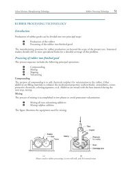
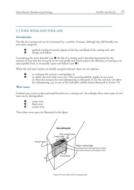
Gradual wear occurs at three principal location on a cutting tool. Accordingly, three main types of tool<br />
wear can be distinguished,<br />
<br />
<br />
<br />
crater wear<br />
flank wear<br />
corner wear<br />
These three wear types are illustrated in the figure:<br />
<strong>Tool</strong> cutting part<br />
Corner wear<br />
Chip contact area<br />
Crater wear<br />
Major cutting edge<br />
perfectly sharp at the beginning of cutting<br />
worn after cutting for some period of time<br />
VB<br />
Flank wear<br />
Types of wear observed in cutting tools
78 <strong>Tool</strong> <strong>Wear</strong> <strong>and</strong> <strong>Tool</strong> <strong>Life</strong><br />
Valery Marinov, Manufacturing Technology<br />
v Crater wear: consists of a concave section on the tool face formed by the action of<br />
the chip sliding on the surface. Crater wear affects the mechanics of the process<br />
increasing the actual rake angle of the cutting tool <strong>and</strong> consequently, making cutting<br />
easier. At the same time, the crater wear weakens the tool wedge <strong>and</strong> increases the<br />
possibility for tool breakage. In general, crater wear is of a relatively small concern.<br />
v Flank wear: occurs on the tool flank as a result of friction between the machined<br />
surface of the workpiece <strong>and</strong> the tool flank. Flank wear appears in the form of so-called<br />
wear l<strong>and</strong> <strong>and</strong> is measured by the width of this wear l<strong>and</strong>, VB, Flank wear affects to<br />
the great extend the mechanics of cutting. Cutting forces increase significantly with flank<br />
wear. If the amount of flank wear exceeds some critical value (VB > 0.5~0.6 mm), the<br />
excessive cutting force may cause tool failure.<br />
actual rake angle<br />
nominal rake angle<br />
chip<br />
tool<br />
crater wear<br />
flank wear l<strong>and</strong><br />
sharp tool profile<br />
VB<br />
workpiece<br />
Cross-section perpendicular to the major cutting<br />
edge of a worn cutting tool showing the effect of<br />
crater wear on the tool rake angle <strong>and</strong> the flank<br />
wear l<strong>and</strong><br />
v Corner wear: occurs on the tool corner. Can be considered as a part of the wear l<strong>and</strong><br />
<strong>and</strong> respectively flank wear since there is no distinguished boundary between the corner<br />
wear <strong>and</strong> flank wear l<strong>and</strong>. We consider corner wear as a separate wear type because<br />
of its importance for the precision of machining. Corner wear actually shortens the<br />
cutting tool thus increasing gradually the dimension of machined surface <strong>and</strong> introduc<br />
ing a significant dimensional error in machining, which can reach values of about<br />
0.03~0.05 mm.<br />
work surface<br />
actual<br />
part shape<br />
theoretical part shape<br />
if no corner wear<br />
V<br />
corner wear reduces<br />
tool length<br />
Dimensional error<br />
caused by tool<br />
corner wear<br />
feed<br />
Sharp cutting tool<br />
Top view showing the effect of tool corner wear on the dimensional<br />
precision in turning
Valery Marinov, Manufacturing Technology<br />
<strong>Tool</strong> life<br />
<strong>Tool</strong> <strong>Wear</strong> <strong>and</strong> <strong>Tool</strong> <strong>Life</strong> 79<br />
<strong>Tool</strong> wear is a time dependent process. As cutting proceeds, the amount of tool wear increases gradually.<br />
But tool wear must not be allowed to go beyond a certain limit in order to avoid tool failure. The most<br />
important wear type from the process point of view is the flank wear, therefore the parameter which has<br />
to be controlled is the width of flank wear l<strong>and</strong>, VB. This parameter must not exceed an initially set safe<br />
limit, which is about 0.4 mm for carbide cutting tools. The safe limit is referred to as allowable wear<br />
l<strong>and</strong> (wear criterion), VB k<br />
. The cutting time required for the cutting tool to develop a flank wear l<strong>and</strong> of<br />
width VB k<br />
is called tool life, T, a fundamental parameter in machining.<br />
The general relationship of VB versus cutting time is shown in the figure (so-called wear curve).<br />
Although the wear curve shown is for flank wear, a similar relationship occur for other wear types. The<br />
figure shows also how to define the tool life T for a given wear criterion VB k<br />
.<br />
VB, mm<br />
break-in<br />
period steady-state wear region failure region<br />
tool<br />
failure<br />
VB k <br />
T<br />
cutting time, min<br />
Flank wear as a function of cutting time. <strong>Tool</strong> life T is defined as the cutting time<br />
required for flank wear to reach the value of VB k<br />
The slope of the wear curve (that is the intensity of tool wear) depends on the same parameters, which<br />
affect the cutting temperature as the wear of cutting tool materials is a process extremely temperature<br />
dependent.<br />
Parameters, which affect the rate of tool wear are<br />
v cutting conditions (cutting speed V, feed f, depth of cut d)<br />
v cutting tool geometry (tool orthogonal rake angle)<br />
v properties of work material<br />
From these parameters, cutting speed is the most important one. As cutting speed is increased, wear rate<br />
increases, so the same wear criterion is reached in less time, i.e., tool life decreases with cutting speed:<br />
VB, mm<br />
cutting speed increases<br />
log T<br />
VB k <br />
V 1<br />
V 2 V 3<br />
T 3<br />
n<br />
VT = C<br />
T 2<br />
T 1<br />
<br />
T 1 T 2<br />
T 3<br />
cutting time, min<br />
V 3<br />
V 2 V 1<br />
log V<br />
(Left) Effect of cutting speed on wear l<strong>and</strong> width <strong>and</strong> tool life for three cutting speeds. (Right) Natural log-log plot of<br />
cutting speed versus tool life.
80 <strong>Tool</strong> <strong>Wear</strong> <strong>and</strong> <strong>Tool</strong> <strong>Life</strong><br />
Valery Marinov, Manufacturing Technology<br />
If the tool life values for the three wear curves are plotted on a natural log-log graph of cutting speed<br />
versus tool life as shown in the right figure, the resulting relationship is a straight line expressed in<br />
equation form called the Taylor tool life equation:<br />
VT n = C<br />
where n <strong>and</strong> C are constants, whose values depend on cutting conditions, work <strong>and</strong> tool material<br />
properties, <strong>and</strong> tool geometry. These constants are well tabulated <strong>and</strong> easily available.<br />
An exp<strong>and</strong>ed version of Taylor equation can be formulated to include the effect of feed, depth of cut<br />
<strong>and</strong> even work material properties.<br />
<strong>Wear</strong> control<br />
As it was discussed earlier, the rate of tool wear strongly depends on the cutting temperature, therefore,<br />
any measures which could be applied to reduce the cutting temperature would reduce the tool wear as<br />
well. The figure shows the process parameters that influence the rate of tool wear:<br />
Cutting tool wear as a function of basic process<br />
parameters<br />
Additional measures to reduce the tool wear include the application of advanced cutting tool materials,<br />
such as coated carbides, ceramics, etc., problem which is discussed in Section 5.8.