Project No. 10731 - Dunn County
Project No. 10731 - Dunn County
Project No. 10731 - Dunn County

You also want an ePaper? Increase the reach of your titles
YUMPU automatically turns print PDFs into web optimized ePapers that Google loves.
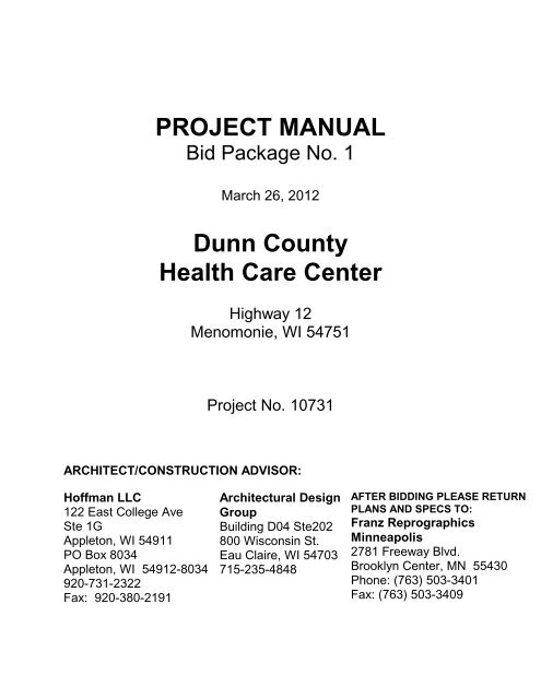
PROJECT MANUAL<br />
Bid Package <strong>No</strong>. 1<br />
March 26, 2012<br />
<strong>Dunn</strong> <strong>County</strong><br />
Health Care Center<br />
Highway 12<br />
Menomonie, WI 54751<br />
<strong>Project</strong> <strong>No</strong>. <strong>10731</strong><br />
ARCHITECT/CONSTRUCTION ADVISOR:<br />
Hoffman LLC<br />
122 East College Ave<br />
Ste 1G<br />
Appleton, WI 54911<br />
PO Box 8034<br />
Appleton, WI 54912-8034<br />
920-731-2322<br />
Fax: 920-380-2191<br />
Architectural Design<br />
Group<br />
Building D04 Ste202<br />
800 Wisconsin St.<br />
Eau Claire, WI 54703<br />
715-235-4848<br />
AFTER BIDDING PLEASE RETURN<br />
PLANS AND SPECS TO:<br />
Franz Reprographics<br />
Minneapolis<br />
2781 Freeway Blvd.<br />
Brooklyn Center, MN 55430<br />
Phone: (763) 503-3401<br />
Fax: (763) 503-3409
INDEX OF SECTIONS<br />
DIVISION 0 - BIDDING REQUIREMENTS, CONTRACT FORMS, AND CONDITIONS OF THE<br />
CONTRACT<br />
Invitation to Bid<br />
00 10 12 - Owner Direct Insurance Program<br />
00 21 13 - Instructions to Bidders<br />
00 31 00 - Available <strong>Project</strong> Information<br />
00 41 00 - Bid Form<br />
00 52 00 - Agreement Forms<br />
00 52 00a - Contract Rider “A” – Safety<br />
00 52 00b - Contract Rider “B” – Insurance<br />
00 52 00c - Contract Rider “C” – Trade Contractors<br />
00 61 13 - Performance and Payment Bonds<br />
00 72 00 - General Conditions<br />
00 73 00 - Supplementary Conditions<br />
00 73 43 - Wage Rates Requirements<br />
00 80 00 - Owner Direst Insurance Program<br />
DIVISION 1 - GENERAL REQUIREMENTS<br />
01 11 00 - Summary of Work<br />
01 11 23 - Owner Purchased Products<br />
01 21 00 - Allowances<br />
01 23 00 - Alternates<br />
01 31 13 - <strong>Project</strong> Coordination<br />
01 31 19 - <strong>Project</strong> Meetings<br />
01 31 26 - Mechanical and Electrical Coordination<br />
01 32 16 - Schedule<br />
01 33 00 - Submittal Procedures<br />
01 41 00 - Regulatory Requirements<br />
01 45 29 - Testing Laboratory Services<br />
01 50 00 - Temporary Facilities and Controls<br />
01 51 13 - Temporary Electricity and Lighting<br />
01 51 23 - Temporary Heating, Cooling, and Ventilating<br />
01 51 36 - Temporary Water and Saniarty Facilities<br />
01 58 00 - <strong>Project</strong> Identification<br />
01 60 00 - Product Requirements<br />
01 71 23 - Field Engineering<br />
01 73 29 - Cutting and Patching<br />
01 74 00 - Cleaning and Waste Management<br />
01 77 00 - Closeout Procedures<br />
01 78 23 - Operation and Maintenance Data<br />
01 78 36 - Warranties and Bonds<br />
01 78 39 - <strong>Project</strong> Record Documents<br />
DIVISION 2 - EXISTING CONDITIONS<br />
024000 - Demolition and Structure Moving<br />
DIVISION 3 - CONCRETE<br />
03 20 00 - Concrete Reinforcement<br />
03 30 00 - Cast-in-Place Concrete<br />
JOB# 10-731 INDEX OF SECTIONS 00100 - 1
DIVISION 4 - MASONRY<br />
04 05 11 - Masonry Mortaring and Gouting<br />
04 20 00 - Unit Masonry<br />
04 72 00 - Cast Stone Masonry<br />
DIVISION 5 - METALS<br />
05 12 00 - Structural Steel Framing<br />
05 40 00 - Cold Formed Metal Framing<br />
05 50 00 - Metal Fabrications<br />
DIVISION 6 – WOOD, PLASTICS, AND COMPOSITES<br />
06 10 00 - Rough Carpentry<br />
06 17 53 - Plate Connected Wood Trusses<br />
06 20 00 - Finish Carpentry<br />
06 41 00 - Architectural Wood Casework<br />
06 42 16 - Wood-Veneer Paneling<br />
06 63 10 - Vinyl Posts and Railings<br />
06 65 00 - Plastic Simulated Wood Trim<br />
06 82 05 - Fiberglass Reinforced Plastic Panels<br />
DIVISION 7 - THERMAL AND MOISTURE PROTECTION<br />
07 21 00 - Thermal Insulation<br />
07 21 19 - Foamed-In-Place Insulation<br />
07 21 26 - Blown Insulation<br />
07 31 13 - Asphalt Shingles<br />
07 31 30 - Stone Coated Metal Roof Shingle<br />
07 46 16 - Aluminum Soffit and Facia<br />
07 46 33 - Plastic Siding<br />
07 46 46 - Fiber Cement Siding<br />
07 53 00 - Elastomeric Membrane Roofing<br />
07 61 00 - Sheet Metal Roofing<br />
07 62 00 - Sheet Metal Flashing and Trim<br />
07 71 23 - Manufactured Gutters and Downspouts<br />
07 81 23 - Intumescent Mastic Fireproofing<br />
07 84 00 - Firestopping<br />
07 90 05 - Joint Sealers<br />
DIVISION 8 - OPENINGS<br />
08 11 13 - Hollow Metal Doors and Frames<br />
08 11 17 - Pre-Finished Steel Door Frames<br />
08 14 16 - Flush Wood Doors<br />
08 14 33 - Stile and Rail Wood Doors<br />
08 31 00 - Access Doors and Panels<br />
08 36 13 - Sectional Doors<br />
08 42 29 - Automatic Entrances<br />
08 43 13 - Aluminum-Framed Storefronts<br />
08 51 13 - Aluminum Windows<br />
08 52 00 - Wood Windows<br />
08 53 13 - Vinyl Windows<br />
08 62 23 - Tubular Skylights<br />
08 71 00 - Door Hardware<br />
JOB# 10-731 INDEX OF SECTIONS 00100 - 2
08 71 14 - Low-Energy Door Operators<br />
08 80 00 - Glazing<br />
08 83 00 - Mirrors<br />
DIVISION 9 - FINISHES<br />
09 21 16 - Gypsum Board Assemblies<br />
09 30 00 - Tiling<br />
09 51 00 - Acoustical Ceiling<br />
09 65 00 - Resilient Flooring<br />
09 68 00 - Carpeting<br />
09 91 00 - Painting<br />
DIVISION 10 - SPECIALTIES<br />
10 14 53 - Traffic Signage and Pavement Markings<br />
10 21 13.13 - Metal Toilet Compartments<br />
10 21 23 - Cubicles<br />
10 26 00 - Impact-Resistant Wall Protection<br />
10 28 00 - Toilet, Bath and Laundry Accessories<br />
10 31 00 - Manufactured Fireplaces<br />
10 44 00 - Fire Protection Specialties<br />
10 51 00 - Lockers<br />
10 56 17 - Wall Mounted Standards and Shelving<br />
10 75 00 - Flagpoles<br />
DIVISION 11 - EQUIPMENT<br />
11 40 00 - Food Service Equipment<br />
DIVISION 12 - FURNISHINGS<br />
12 35 30 - Residential Casework<br />
12 36 00 - Countertops<br />
DIVISION 21 – FIRE SUPPRESSION<br />
21 05 00 - General Fire Protection Requirements<br />
21 05 10 - Fire Protecting Piping<br />
21 13 13 - Wet-Pipe Sprinkler System<br />
21 13 16 - Dry-Pipe Sprinkler System<br />
DIVISION 22 - PLUMBING<br />
22 05 00 - General Plumbing Requirements<br />
22 05 03 - Pipe and Pipe Fittings<br />
22 05 23 - Valves<br />
22 05 29 - Supports & Anchors<br />
22 07 00 - Plumbing Insulation<br />
22 10 00 - Piping Specialties<br />
22 10 01 - Plumbing Specialties<br />
22 30 00 - Plumbing Equipment<br />
22 40 00 - Plumbing Fixtures<br />
JOB# 10-731 INDEX OF SECTIONS 00100 - 3
DIVISION 23 - HEATING, VENTILATING, AND AIR CONDITIONING<br />
23 05 00 - General HVAC Requirements<br />
23 05 03 - Piping and Fittings<br />
23 05 14 - Variable Frequency Drive<br />
23 05 15 - Piping Specialties<br />
23 05 23 - Valves<br />
23 05 29 - Supports and Anchors<br />
23 05 48 - Vibration Isolation<br />
23 05 93 - Testing, Adjusting and Balancing<br />
23 07 00 - Ductwork Insulation<br />
23 07 01 - HVAC Piping Insulation<br />
23 09 00 - Temperature Control<br />
23 20 00 - HVAC Pumps<br />
23 21 14 - Ground Loop Heat Exchanger System<br />
23 31 00 - Ductwork<br />
23 33 00 - Ductwork Accessories<br />
23 34 13 - Power Roof Ventilators<br />
23 37 00 - Air Outlets and Inlets<br />
23 52 34 - Boilers<br />
23 72 00 - Energy Recovery Units<br />
23 81 07 - Rooftop Heating, Cooling and Make-up Air Unit (Gas Fired)<br />
23 81 43 - Heat Pump Units<br />
23 82 00 - Terminal Heat Transfer Units<br />
23 84 15 - Humidifiers<br />
DIVISION 26 - ELECTRICAL<br />
26 00 10 - General Electrical Requirements<br />
26 00 20 - Temporary Service<br />
26 05 00 - Basic Electrical Materials and Methods<br />
26 05 03 - Wiring Connections<br />
26 05 19 - Building Wire and Cable<br />
26 05 33 - Raceway and Boxes<br />
26 09 23 - Occupancy Sensors<br />
26 13 44 - Communications Distribution<br />
26 24 16 - Panelboards<br />
26 27 15 - Electrical Utility Services<br />
26 27 26 - Wiring Devices<br />
26 28 19 - Enclosed Switches<br />
26 32 13 - Engine Generators and Transfer Switch<br />
26 50 00 - Lumiaries<br />
DIVISION 27 - COMMUNICATIONS<br />
27 05 11 - Requirements for Communications Installation<br />
27 10 00 - Telecommunications Cabling<br />
27 41 00 - TV Distribution<br />
27 52 23 - Emergency Call and Perimeter Alarm System<br />
27 52 24 - Emergency Call System<br />
DIVISION 28 – ELECTRONIC SAFETY AND SECURITY<br />
28 31 00 - Fire Alarm<br />
JOB# 10-731 INDEX OF SECTIONS 00100 - 4
DIVISION 31 - EARTHWORK<br />
31 10 00 - Site Clearing<br />
31 20 00 - Earth Moving<br />
31 25 00 - Eroision and Sediment Control<br />
31 37 00 - Riprap<br />
DIVISION 32 - EXTERIOR IMPROVEMENTS<br />
32 11 23 - Aggregate Base Courses<br />
32 12 00 - Flexible Paving<br />
32 13 13 - Concrete Paving<br />
32 13 14 - Concrete Sidewalks and Aprons<br />
32 16 00 - Curbs and Gutters<br />
32 17 23.13 - Painted Pavement Markings<br />
32 17 26 - Tactile Warning Surfacing<br />
32 31 23 - Plastic Fences and Gates<br />
32 92 00 - Turfs and Grasses<br />
32 93 00 - Plants<br />
DIVISION 33 - UTILITIES<br />
33 04 00 - Trenching and Site Utilities<br />
33 11 00 - Water Utilities<br />
33 31 00 - Sanitary Sewerage Utilities<br />
33 40 00 - Site Drainage Utilities<br />
END OF SECTION 00100<br />
JOB# 10-731 INDEX OF SECTIONS 00100 - 5
1<br />
2<br />
3<br />
4<br />
5<br />
6<br />
7<br />
8<br />
9<br />
10<br />
11<br />
12<br />
13<br />
14<br />
15<br />
16<br />
17<br />
18<br />
19<br />
20<br />
21<br />
22<br />
23<br />
24<br />
25<br />
26<br />
27<br />
28<br />
29<br />
30<br />
31<br />
32<br />
33<br />
34<br />
35<br />
36<br />
37<br />
38<br />
39<br />
40<br />
41<br />
42<br />
43<br />
44<br />
45<br />
46<br />
47<br />
48<br />
49<br />
50<br />
51<br />
52<br />
53<br />
54<br />
55<br />
56<br />
57<br />
58<br />
59<br />
INVITATION TO BID<br />
DUNN COUNTY NEW HEALTH CARE<br />
CENTER<br />
FOR<br />
DUNN COUNTY<br />
PURCHASING DEPT.<br />
800 WILSON AVE<br />
MENOMONIE, WI<br />
ARCHTECT:<br />
HOFFMAN, LLC<br />
CONSTRUCTION MANAGER:<br />
THE SAMUELS GROUP, INC.<br />
BIDS DUE: APRIL 12, 2012 at 2:00 PM LOCAL<br />
TIME. PUBLIC BID OPENING WILL FOLLOW<br />
A pre-bid meeting is scheduled for March 29 at<br />
10:00 am at the existing <strong>Dunn</strong> <strong>County</strong> Health Care<br />
Center, 3001 Highway 12 E., Menomonie, WI<br />
54751.<br />
Sealed Bids for the <strong>Project</strong> designated above will<br />
be received on behalf of the Owner by the<br />
Construction Manager, The Samuels Group, at the<br />
above location.<br />
All bids will be publicly opened and read at the<br />
specified time and date indicated above by the<br />
Owner or his designee.<br />
The Work includes construction of a new Health<br />
Care Center complex comprised of 12 new single<br />
story buildings located on one project site. Review<br />
bid documents and Bid Category description for<br />
full description of the work. Construction Schedule<br />
is Start May 2012 and Complete July 2013.<br />
Documents may be viewed at The Samuels Group<br />
in Wausau, WI; Isqft, Franz Reprographics Online<br />
Plan Room, Samuels Group FTP Site, Select<br />
Builders Exchanges in Wisconsin, Iowa and<br />
Minnesota.<br />
Copies of the above documents may be obtained<br />
on or after March 26, 2012<br />
You may view and order bid documents by going<br />
to the Franz Reprographics web site at<br />
www.franzrepro.com, and selecting the Franz<br />
Public Plan Room. A hard copy set of Bid<br />
documents will have a refundable deposit of<br />
$225. Deposit check to be made out to Franz<br />
Reprographics. A non-refundable fee of $60 will<br />
be due to Franz Reprographics for shipping. To<br />
60<br />
61<br />
62<br />
63<br />
64<br />
65<br />
66<br />
67<br />
68<br />
69<br />
70<br />
71<br />
72<br />
73<br />
74<br />
75<br />
76<br />
view the project click on “Pink” Guest View<br />
Button. Otherwise please complete the log-in<br />
registration form to establish an account which<br />
allows you to order the project plans and specs.<br />
Once you have selected the project, please<br />
review the Bid Details for information on<br />
ordering documents. To receive Bid<br />
Addendums, General <strong>No</strong>tifications etc, for this<br />
project you must place the following email<br />
address notice@plancommand.net in your<br />
list of Outlook Contacts and indicate that it is a<br />
Safe Sender: There is a ?Help button you can<br />
select for assistance with using the Online Plan<br />
Room. If you still have problems, please contact<br />
Franz Reprographics by phone at 763-503-<br />
3401/800-288-8541<br />
Bid Security in the amount of five (5) percent of the<br />
Bid must accompany each Bid in accord with the<br />
Instructions to Bidders.<br />
The Owner reserves the right to waive<br />
irregularities and to accept any bid, reject any and<br />
all bids, and upon acceptance of any bid, to<br />
thereafter accept revisions or modifications on<br />
such bid.<br />
Invitation to Bid<br />
00 11 16-1
1<br />
2<br />
3<br />
4<br />
5<br />
6<br />
7<br />
8<br />
9<br />
10<br />
11<br />
12<br />
13<br />
14<br />
15<br />
16<br />
17<br />
18<br />
19<br />
20<br />
21<br />
22<br />
23<br />
24<br />
25<br />
26<br />
27<br />
28<br />
29<br />
30<br />
31<br />
32<br />
33<br />
34<br />
35<br />
36<br />
37<br />
38<br />
39<br />
40<br />
41<br />
42<br />
43<br />
44<br />
45<br />
46<br />
47<br />
48<br />
49<br />
50<br />
51<br />
52<br />
53<br />
54<br />
55<br />
56<br />
57<br />
SECTION 00 21 13<br />
INSTRUCTIONS TO BIDDERS<br />
GENERAL<br />
To be considered, Bids must be made in accord with these Instructions to Bidders. Bidders should<br />
reference Section 01 11 00 Summary of Work to review the Bid Categories for this project.<br />
DOCUMENTS<br />
Contact the Architect or Construction Manager for instructions for obtaining bid documents.<br />
EXAMINATION<br />
Carefully examine the Procurement Documents which include the proposed Contract Documents and<br />
the construction site to obtain first-hand knowledge of existing conditions. Each Bidder, by submitting<br />
its bid, represents that Bidder has examined the Procurement Documents, inspected the site,<br />
understands the provisions of the Procurement Documents, and has become familiar with the local<br />
conditions under which the Work is to be performed. Bidders will not be entitled to extra payments or<br />
Contract Time extensions for conditions which could have been determined by carefully examining the<br />
site, subsurface information, and the Procurement Documents.<br />
Copies of standards referenced in the <strong>Project</strong> Manual are available for review at the Architect's office,<br />
or may be seen at College or University libraries.<br />
ADDENDA<br />
All changes in or interpretations of the Procurement Documents prior to the bid opening will be made by<br />
written addenda issued by the Architect to each recipient of the Procurement Documents recorded by<br />
the Architect. All addenda will be issued not later than 24 hours prior to bid opening.<br />
PROOF OF COMPETENCY OF BIDDER<br />
Any Bidder may be required to furnish evidence satisfactory to the Construction Manager that the<br />
Bidder have sufficient means, expertise, financial ability, and experience in the types of work Bid to<br />
assure completion of the Contract in a satisfactory manner.<br />
QUESTIONS<br />
Submit all questions about the Procurement Documents to the Architect, in writing, not later than 5 days<br />
prior to Bid Date. Replies will be issued to all Bidders of Record as Addenda to the Procurement<br />
Documents and will become part of the Contract. The Architect and Owner will not be responsible for<br />
oral clarification. Questions received after this time cannot be answered.<br />
SUBSTITUTIONS<br />
To obtain approval to use unspecified products, submit Substitution Request Form not later than 10<br />
days prior to Bid Date. Requests received after this time will not be considered. Utilize Substitution<br />
Request Form at the end of Section 01 60 00. If the Product is acceptable, the Architect will so indicate<br />
by Addendum issued to all Bidders of Record. Refer to Section 01 60 00 of the Specifications for<br />
additional information.<br />
PREPARATION OF BIDS<br />
Instructions to Bidders<br />
00 21 13-1
1<br />
2<br />
3<br />
4<br />
5<br />
6<br />
7<br />
8<br />
9<br />
10<br />
11<br />
12<br />
13<br />
14<br />
15<br />
16<br />
17<br />
18<br />
19<br />
20<br />
21<br />
22<br />
23<br />
24<br />
25<br />
26<br />
27<br />
28<br />
29<br />
30<br />
31<br />
32<br />
33<br />
34<br />
35<br />
36<br />
37<br />
38<br />
39<br />
40<br />
41<br />
42<br />
43<br />
44<br />
45<br />
46<br />
47<br />
48<br />
49<br />
50<br />
51<br />
52<br />
53<br />
54<br />
55<br />
56<br />
57<br />
58<br />
<strong>Dunn</strong> <strong>County</strong> is a governmental entity and is exempt from Wisconsin Sales and Use Taxes on certain<br />
purchases it makes.<br />
Subject to Contracting Requirements and administrative procedures set forth in Section 01 11 23:<br />
Owner Purchased Products, the <strong>County</strong> intends to purchase directly such materials, equipment, and/or<br />
other incidental services as designated in the Bid Form by Bidder as "Maximum cost to Owner for<br />
Owner-Direct Purchases".<br />
NOTE Include all materials and equipment specified in Section 11 40 00 - Foodservice Equipment in<br />
Part 2 of your Base Bid.<br />
The BASE BID is the stipulated sum to perform all the Work including a guaranteed maximum sum<br />
for Owner-Direct Purchases (including applicable Wisconsin Sales and Use Taxes).<br />
Enter in Part 1 of the Base Bid the guaranteed maximum sum for Owner-Direct Purchases including<br />
applicable Wisconsin Sales and Use Taxes.<br />
Enter in Part 2 of the Base Bid the stipulated sum for all other costs to perform all the Work including<br />
without limitation: labor, services, Contract Administration, all incidental materials and equipment<br />
(excluded from Part 1), and all costs associated with providing administrative assistance to the Owner<br />
to facilitate Owner-Direct Purchases as more fully described in the Procurement Documents. Include<br />
all Work of Section 11 40 00.<br />
Prepare Bids on unaltered Bid Forms bound in the <strong>Project</strong> Manual. Submit two copies. Bids shall be<br />
signed with name typed below signature. Where Bidder is a corporation, Bids must be signed with the<br />
legal name of the corporation followed by the name of the State of incorporation and the legal signature<br />
of an officer authorized to bind the corporation to Contract. Do not submit <strong>Project</strong> Manual with Bid.<br />
ALTERNATIVE BIDS<br />
Where Alternative Bids are required in the Bid Form, Bidders shall fill in each alternative bid with a bid<br />
price. There will be no division of awards between Base Bid and accepted alternative bids.<br />
Prepare the Alternative Bid in a similar manner as the Base Bid except identification of Parts 1 and 2 is<br />
not required, and all sales and use taxes must be included in the Alternative Bid. Should the Owner<br />
elect to accept the Alternative Bid, then any products the Owner elects to purchase directly, together<br />
with the applicable sales and use taxes will be credited to the Owner and the balance of the Alternative<br />
Bid added to the Contract Sum.<br />
UNIT PRICE ITEMS<br />
When unit price items are included in the Procurement Documents, the bidder shall indicate, in figures,<br />
a unit price for each separate item. The acceptance of bid unit prices shall be a condition of contract<br />
award.<br />
PRE-BID CONFERENCE<br />
The Architect and Construction Manager will hold a pre-bid conference on March 29 at 10:00 am at the<br />
existing <strong>Dunn</strong> <strong>County</strong> Health Care Center, 3001 Highway 12 E., Menomonie, WI 54751. The<br />
conference is open to all Bidders and Suppliers. Attendance is not mandatory. The conference will be<br />
held to determine that the Contract Documents, contract terms, and related matters are understood by<br />
the Bidders. Any misunderstanding as to work procedure, scope of the work, project schedules, and<br />
similar items are to be discussed and resolved. All pertinent agreements reached will become a part of<br />
the project by written addendum.<br />
Place and exact time of conference will be determined by the Architect and Construction Manager and<br />
will be communicated by telephone or letter.<br />
Instructions to Bidders<br />
00 21 13-2
1<br />
2<br />
3<br />
4<br />
5<br />
6<br />
7<br />
8<br />
9<br />
10<br />
11<br />
12<br />
13<br />
14<br />
15<br />
16<br />
17<br />
18<br />
19<br />
20<br />
21<br />
22<br />
23<br />
24<br />
25<br />
26<br />
27<br />
28<br />
29<br />
30<br />
31<br />
32<br />
33<br />
34<br />
35<br />
36<br />
37<br />
38<br />
39<br />
40<br />
41<br />
42<br />
43<br />
44<br />
45<br />
46<br />
47<br />
48<br />
49<br />
50<br />
51<br />
52<br />
53<br />
54<br />
55<br />
56<br />
57<br />
BID SECURITY<br />
Make Bid Security payable to <strong>Dunn</strong> <strong>County</strong> in the amount of five (5) percent of the total Bid Sum, not<br />
just Part 2. Security shall be either certified check or bid bond issued by surety licensed to conduct<br />
business in the State of Wisconsin. The successful Bidder's security will be retained until he has<br />
signed a Contract and furnished the required payment and performance bonds. The Owner will retain<br />
the security of all Bidders until the successful bidder enters into Contract or until 45 days after bid<br />
opening, whichever is the shorter. If any Bidder refuses to enter into a Contract, the Owner will retain<br />
his Bid Security as liquidated damages, but not as a penalty. Submit Bid Security with Bid.<br />
PERFORMANCE BOND AND LABOR AND MATERIALS PAYMENT BOND<br />
Each successful Bidder shall furnish and pay for a Performance Bond and Labor and Materials<br />
Payment Bond. See Subparagraph 11.5 of the Supplementary Conditions. Reference <strong>Dunn</strong> <strong>County</strong><br />
Code of Ordinances Chapter 7.<br />
SUBMITTAL<br />
Submit Bid and Bid Security in an opaque sealed envelope. Identify the envelope with <strong>Project</strong> name,<br />
and name of Bidder. Submit Bids in accord with the Invitation to Bid. Do not submit <strong>Project</strong> Manual<br />
with Bid. Facsimile bids not acceptable.<br />
MODIFICATION AND WITHDRAWAL<br />
Bids may not be modified after submittal. Bidders may withdraw Bids at any time before bid opening,<br />
but may not resubmit them. <strong>No</strong> Bid may be withdrawn or modified after the bid opening except where<br />
the award of Contracts has been delayed for more than 45 days from day of Bid opening.<br />
DISQUALIFICATION<br />
The Owner reserves the right to disqualify Bids, before or after opening upon evidence of collusion with<br />
intent to defraud or other illegal practices upon the part of the Bidder.<br />
OPENING<br />
Bids will be opened as announced in the Invitation to Bid.<br />
AWARD<br />
The Owner reserves the right to waive irregularities and accept any Bid, reject any and all Bids, and<br />
upon acceptance of any Bid, to thereafter accept revisions or modifications on such Bid.<br />
If two or more Bidders submit identical Bids, the Owner may make award to that Bidder of his choice,<br />
and such decision shall be final.<br />
Awards will not be made to any Bidder in default of a Contract with the Owner, or to any Bidder having<br />
as his agent or employee any individual previously in default or guilty of misrepresentation.<br />
Bid results may be published in construction periodicals.<br />
NOTICE TO PROCEED<br />
Written notice of award to a Bidder in the form of a letter from the Construction Manager mailed or<br />
delivered to the address shown on the Bid Form will be considered sufficient notice of acceptance of<br />
Bid, intent to award the Contract, and "<strong>No</strong>tice to Proceed" with the Work.<br />
EXECUTION OF AGREEMENT<br />
Instructions to Bidders<br />
00 21 13-3
1<br />
2<br />
3<br />
4<br />
5<br />
6<br />
7<br />
8<br />
9<br />
10<br />
11<br />
12<br />
13<br />
14<br />
15<br />
16<br />
17<br />
18<br />
19<br />
20<br />
21<br />
The Agreement Forms which the accepted Bidder, as Contractor, will be required to execute is<br />
indicated in the <strong>Project</strong> Manual.<br />
The accepted Bidder shall assist and cooperate with the Construction Manager in preparing the formal<br />
Agreement, and within ten days following its presentation shall execute same and return it to the<br />
Construction Manager. Failure to execute Agreement and return it to Construction Manager within time<br />
indicated shall be considered by Construction Manager as refusal by accepted Bidder to enter into the<br />
Contract.<br />
At or prior to delivery of the signed Agreement, the Contractor shall deliver to the Construction Manager<br />
the Performance Bond and Labor and Material Payment Bond and the policies of insurance or<br />
insurance certificates as required by the Contract Documents. All bonds and policies of insurance shall<br />
be approved by the Construction Manager before the accepted Bidder may proceed with the Work.<br />
Failure or refusal to furnish bonds or insurance policies or certificates in a timely manner and in a form<br />
satisfactory to the Construction Manager shall not serve to waive any requirements of the Contract<br />
Documents, including time of completion.<br />
End of Instructions to Bidders<br />
Instructions to Bidders<br />
00 21 13-4
1<br />
2<br />
3<br />
4<br />
5<br />
6<br />
7<br />
8<br />
9<br />
10<br />
11<br />
12<br />
13<br />
14<br />
15<br />
16<br />
17<br />
18<br />
19<br />
20<br />
21<br />
22<br />
23<br />
24<br />
25<br />
26<br />
27<br />
28<br />
29<br />
30<br />
31<br />
32<br />
33<br />
34<br />
35<br />
36<br />
37<br />
38<br />
39<br />
40<br />
41<br />
42<br />
43<br />
44<br />
45<br />
46<br />
47<br />
SECTION 00 31 00<br />
AVAILABLE PROJECT INFORMATION<br />
USING THE PROJECT MANUAL<br />
The information contained in this <strong>Project</strong> Manual has been organized utilizing MASTERFORMAT, 2004<br />
Edition, a publication jointly produced by the Constructions Specifications Institute (CSI) and<br />
Construction Specifications Canada (CSC).<br />
The <strong>Project</strong> Manual consists of three major parts:<br />
Procurement Requirements<br />
Contracting Requirements<br />
Specifications<br />
Specifications have been divided into 33 Divisions. <strong>No</strong>te that not all Divisions are necessarily used.<br />
The Divisions are further divided into Sections classifying work results.<br />
Work and requirements are specified in particular Divisions and Sections according to the TYPE of<br />
Work to be furnished NOT according to trade jurisdiction nor local practices.<br />
NOTICE TO BIDDERS<br />
The following information regarding site survey and subsurface conditions was obtained or otherwise<br />
acquired by the Owner for his use. It is presented here to aid the Bidder in the preparation of his bid.<br />
Neither Owner, Construction Manager, nor Architect warrant the accuracy of this information, which has<br />
been furnished or prepared by other parties. Bidders should verify this information prior to submitting<br />
their bid.<br />
SITE SURVEY<br />
The extent of site survey information available, is included in the bid documents.<br />
SUBSURFACE INVESTIGATION<br />
A geotechnical report has been conducted by Owner. The written report and soil boring report is bound<br />
immediately following this section.<br />
End of Available <strong>Project</strong> Information<br />
2006.07.00 Available <strong>Project</strong> Information<br />
00000 00 31 00-1
1<br />
2<br />
3<br />
4<br />
5<br />
6<br />
7<br />
8<br />
9<br />
10<br />
11<br />
12<br />
13<br />
14<br />
15<br />
16<br />
17<br />
18<br />
19<br />
20<br />
21<br />
22<br />
23<br />
24<br />
25<br />
26<br />
27<br />
28<br />
29<br />
30<br />
31<br />
32<br />
33<br />
34<br />
35<br />
36<br />
37<br />
38<br />
39<br />
40<br />
41<br />
42<br />
43<br />
44<br />
45<br />
46<br />
47<br />
48<br />
49<br />
50<br />
51<br />
52<br />
53<br />
54<br />
55<br />
56<br />
57<br />
58<br />
59<br />
60<br />
61<br />
62<br />
63<br />
64<br />
SECTION 00 41 00<br />
BID FORM<br />
PROJECT: DUNN COUNTY HEALTH CARE CENTER<br />
HIGHWAY 12<br />
MENOMONIE, WI 54751<br />
BIDS TO: DUNN COUNTY – PURCHASING DEPT.<br />
ATTN: PATTY ISAACSON<br />
800 WILSON AVE<br />
MENOMONIE, WI 54751<br />
I (We) ________________________________________________________________________________<br />
(A Corporation) (A Partnership) (An Individual)<br />
Strike out those that do not apply<br />
Of ___________________________________________________________________________________<br />
Street City State Zip<br />
______________________________________________________________________________________<br />
Telephone Number Fax Number Email<br />
a Bona Fide Prime Bidder, have received the Procurement Documents which include the <strong>Project</strong> Manual and<br />
Drawings prepared by Hoffman, LLC., dated _____________, 2012 for the above referenced project. I (We) have<br />
also received Addenda <strong>No</strong>s. ____________, and have included their provisions in this Bid.<br />
I (We) have examined the Procurement Documents noted above including all referenced AIA Documents, and<br />
agree to enter into and execute a Contract, if awarded, on the basis of this Bid, and to furnish guarantee bonds in<br />
accord with Article 11 of the General Conditions of the Contract for Construction.<br />
BASE BID<br />
I (We) will perform all the Work except for Work described in Alternatives, for the stipulated sum of<br />
__________________________________________________________________________________________<br />
____________________________ Dollars ($_____________________________________________).<br />
which is the sum of Parts 1 and 2 following:<br />
PART 1.<br />
Maximum cost to Owner for Owner-Direct Purchases Including applicable Wisconsin Sales and Use<br />
Taxes is ___________________________________________________________________________<br />
_____________________________________Dollars ($______________________________________ )<br />
PART 2.<br />
Stipulated sum for all other costs excluded from Part 1 above to perform all the Work is<br />
__________________________________________________________________________________<br />
_____________________________________Dollars ($______________________________________ )<br />
Bid Form<br />
00 41 00-1
1<br />
2<br />
3<br />
4<br />
5<br />
6<br />
7<br />
8<br />
9<br />
10<br />
11<br />
12<br />
13<br />
14<br />
15<br />
16<br />
17<br />
18<br />
19<br />
20<br />
21<br />
22<br />
23<br />
24<br />
25<br />
26<br />
27<br />
28<br />
29<br />
30<br />
31<br />
32<br />
33<br />
34<br />
35<br />
36<br />
37<br />
38<br />
39<br />
40<br />
41<br />
42<br />
43<br />
44<br />
45<br />
46<br />
47<br />
48<br />
49<br />
50<br />
51<br />
52<br />
53<br />
54<br />
55<br />
56<br />
57<br />
58<br />
59<br />
60<br />
61<br />
62<br />
63<br />
64<br />
ALTERNATIVE BIDS<br />
Alternative Bids are more fully described in Section 01 23 00 of the Specifications. All Prime Bidders must<br />
indicate the stipulated sum to be added to or deducted from their Base Bid or indicate "no change". A "no bid"<br />
entry, or failure to enter a sum will be considered a "no change" to the Base Bid.<br />
ALTERNATIVE BID NO. 1 – IN FLOOR HEAT<br />
If the Owner elects to accept this alternative, add to or deduct from my (our) Base Bid the stipulated sum of<br />
____________________________________________ Dollars ( $ _______________________________).<br />
ALTERNATIVE BID NO. 2 – SOLAR TUBES<br />
If the Owner elects to accept this alternative, add to or deduct from my (our) Base Bid the stipulated sum of<br />
____________________________________________ Dollars ( $ _______________________________).<br />
ALTERNATIVE BID NO. 3 – SEPARATE ENTRY DRIVE<br />
If the Owner elects to accept this alternative, add to or deduct from my (our) Base Bid the stipulated sum of<br />
____________________________________________ Dollars ( $ _______________________________).<br />
ALTERNATIVE BID NO. 4 – HARDWOOD WALL BASE<br />
If the Owner elects to accept this alternative, add to or deduct from my (our) Base Bid the stipulated sum of<br />
____________________________________________ Dollars ( $ _______________________________).<br />
ALTERNATIVE BID NO. 5 – LARGE CORE FRONT ELEVATION BRICK & FOUNDATION WALL<br />
If the Owner elects to accept this alternative, add to or deduct from my (our) Base Bid the stipulated sum of<br />
____________________________________________ Dollars ( $ _______________________________).<br />
ALTERNATIVE BID NO. 6 – CEMENT SIDING<br />
If the Owner elects to accept this alternative, add to or deduct from my (our) Base Bid the stipulated sum of<br />
____________________________________________ Dollars ( $ _______________________________).<br />
ALTERNATIVE BID NO. 7 – ODIP INSURANCE<br />
If the Owner elects to accept this alternative, add to or deduct from my (our) Base Bid the stipulated sum of<br />
____________________________________________ Dollars ( $ _______________________________).<br />
ALTERNATIVE BID NO. 8 – ENHANCED HVAC CONTROL SYSTEM<br />
If the Owner elects to accept this alternative, add to or deduct from my (our) Base Bid the stipulated sum of<br />
____________________________________________ Dollars ( $ _______________________________).<br />
ALTERNATIVE BID NO. 9 – ENHANCED ELOPEMENT SYSTEM<br />
If the Owner elects to accept this alternative, add to or deduct from my (our) Base Bid the stipulated sum of<br />
____________________________________________ Dollars ( $ _______________________________).<br />
ALTERNATIVE BID NO. 10 – VINYL CLAD WOOD WINDOWS<br />
If the Owner elects to accept this alternative, add to or deduct from my (our) Base Bid the stipulated sum of<br />
____________________________________________ Dollars ( $ _______________________________).<br />
ALTERNATIVE BID NO. 11 – ENHANCED NURSE CALL SYSTEM<br />
If the Owner elects to accept this alternative, add to or deduct from my (our) Base Bid the stipulated sum of<br />
____________________________________________ Dollars ( $ _______________________________).<br />
ALTERNATIVE BID NO. 12 – EXPAND GENERATOR SYSTEM<br />
If the Owner elects to accept this alternative, add to or deduct from my (our) Base Bid the stipulated sum of<br />
____________________________________________ Dollars ( $ _______________________________).<br />
Bid Form<br />
00 41 00-2
1<br />
2<br />
3<br />
4<br />
5<br />
6<br />
7<br />
8<br />
9<br />
10<br />
11<br />
12<br />
13<br />
14<br />
15<br />
16<br />
17<br />
18<br />
19<br />
20<br />
21<br />
22<br />
23<br />
24<br />
25<br />
26<br />
27<br />
28<br />
29<br />
30<br />
31<br />
32<br />
33<br />
34<br />
35<br />
36<br />
37<br />
38<br />
39<br />
40<br />
41<br />
42<br />
43<br />
44<br />
45<br />
46<br />
47<br />
48<br />
49<br />
50<br />
51<br />
52<br />
53<br />
54<br />
55<br />
56<br />
57<br />
58<br />
59<br />
60<br />
61<br />
62<br />
63<br />
64<br />
ALTERNATIVE BID NO. 13 – METAL STANDING SEAM ROOFING<br />
If the Owner elects to accept this alternative, add to or deduct from my (our) Base Bid the stipulated sum of<br />
____________________________________________ Dollars ( $ _______________________________).<br />
ALTERNATIVE BID NO. 14 – METAL SHAKE ROOFING<br />
If the Owner elects to accept this alternative, add to or deduct from my (our) Base Bid the stipulated sum of<br />
____________________________________________ Dollars ( $ _______________________________).<br />
ALTERNATIVE BID NO. 15 – OAK CHAIR RAIL<br />
If the Owner elects to accept this alternative, add to or deduct from my (our) Base Bid the stipulated sum of<br />
____________________________________________ Dollars ( $ _______________________________).<br />
ALTERNATIVE BID NO. 16 – PLANK STYLE VINYL FLOORING IN LIEU OF SHEET VINYL<br />
If the Owner elects to accept this alternative, add to or deduct from my (our) Base Bid the stipulated sum of<br />
____________________________________________ Dollars ( $ _______________________________).<br />
ALTERNATIVE BID NO. 17 – RE-USE GEOTHERMAL TEST WELL<br />
If the Owner elects to accept this alternative, add to or deduct from my (our) Base Bid the stipulated sum of<br />
____________________________________________ Dollars ( $ _______________________________).<br />
ALTERNATIVE BID NO. 18 – FLUSH WOOD DOORS<br />
If the Owner elects to accept this alternative, add to or deduct from my (our) Base Bid the stipulated sum of<br />
____________________________________________ Dollars ( $ _______________________________).<br />
ALLOWANCES<br />
I (We) have included all allowances as stated in the Contract Documents.<br />
SUBCONTRACTOR LIST<br />
I (We) understand that after Bid opening, to be considered for contract Award, I (we) must submit a list of<br />
Subcontractors in accordance with the Instructions to Bidders.<br />
WISCONSIN SALES/USE TAXES<br />
I (We) have included all Wisconsin Sales/Use Taxes applicable to this <strong>Project</strong> in accordance with current<br />
Wisconsin Statutes and regulations of the Wisconsin Department of Revenue.<br />
BID SECURITY<br />
I (We) have attached the required Bid Security to this Bid.<br />
__________________________________<br />
Firm Name<br />
By (Signature) __________________________________<br />
Printed Name and Title __________________________________<br />
Attested __________________________________<br />
(Authorized Corporate Officer)<br />
Dated , 20__ (Affix Corporate Seal Here)<br />
End of Bid Form<br />
Bid Form<br />
00 41 00-3
1<br />
2<br />
3<br />
4<br />
5<br />
6<br />
7<br />
8<br />
9<br />
10<br />
11<br />
12<br />
13<br />
14<br />
15<br />
16<br />
17<br />
18<br />
19<br />
20<br />
21<br />
22<br />
23<br />
24<br />
25<br />
26<br />
27<br />
28<br />
29<br />
30<br />
31<br />
32<br />
33<br />
SECTION 00 52 00<br />
AGREEMENT FORM<br />
REFERENCED STANDARD<br />
The "Standard Form of Agreement Between Owner and Contractor", AIA Document A101-2007, is not<br />
bound in this <strong>Project</strong> Manual, but is included by this reference; is a part of the Procurement Documents;<br />
and is incorporated herein as fully as if here set-forth. This Form of Agreement will be used between<br />
Owner and each Contractor.<br />
AIA Document A101-2007 as supplemented may be examined at the office of the Architect or at the<br />
Construction Manager's place of business.<br />
The following Riders will be made part of the Standard Form of Agreement between Owner and<br />
Contractor.<br />
1. Rider A – Safety<br />
2. Rider B – Insurance<br />
3. Rider C – Trade Contractors and Material Suppliers<br />
Copies of AIA Document A101-2007 may be purchased from:<br />
AIA Wisconsin<br />
321 S. Hamilton Street<br />
Madison, WI 53703<br />
Phone (608) 257-8477<br />
Fax (608) 257-0242<br />
Agreement Form<br />
00 52 00-1
00 52 00a<br />
NEW DUNN COUNTY HEALTH CARE CENTER<br />
RIDER A<br />
LABOR OR LABOR/MATERIAL SUPPLIERS ONLY<br />
SAFETY. The prevention of accidents or injuries on, about, or in the vicinity of the project site is the Trade<br />
Contractor's responsibility. The Trade Contractor, its Subcontractors, and Suppliers must perform their Work in a safe<br />
manner, must fully comply with safety measures initiated by the Owner or imposed by the Contract Documents, must adhere<br />
to the applicable laws, ordinances, rules, regulations, codes and orders of public authorities bearing upon the safety of<br />
persons or property or their protection from damages, injury or loss, and must abide with all Federal and State OSHA<br />
requirements relative to safety and the prevention of accidents or injuries.<br />
The Trade Contractor shall be solely responsible for the protection and safety of its employees, its Subcontractor's<br />
employees, and Supplier's employees, for the final selection of all safety methods and means, for required safety reports and<br />
records, for daily inspection of its Work area and its employees' safety equipment, and for the continual instruction of its<br />
employees on health and safety, including weekly safety meetings. The Trade Contractor must actively promote safe<br />
working performances and practices on the part of its employees, its Subcontractor's employees, and Supplier's employees.<br />
The Trade Contractor must establish and maintain a safety program implementing safety measures, policies and standards<br />
conforming, on a comprehensive basis, to its obligations under these paragraphs which safety program shall include<br />
provisions for selection of safety methods and means, conveyance of information and instruction with regard to those safety<br />
methods and means to its employees, Subcontractors, and Suppliers, safety meetings of its employees at least once a week,<br />
maintenance of required safety reports and records, periodic inspections of its Work area and equipment to detect and<br />
correct hazardous conditions, safety rule violations and unsafe work practices, and enforcement of corrective actions as<br />
required.<br />
The Trade Contractor shall stop any part of the Work which the Owner deems unsafe until proper corrective measures have<br />
been taken but failure on the part of the Owner to stop unsafe Work shall in no way relieve the Trade Contractor of its<br />
responsibility therefor. The Trade Contractor shall indemnify the Owner for fines, penalties, damages or expenses incurred<br />
by the Owner because of the Contractor's failure to comply with safety requirements.<br />
HARDHATS, PROTECTIVE CLOTHING AND EQUIPMENT. All personnel are to wear an approved<br />
hardhat, safety shoes and glasses and goggles and comply with OSHA clothing standards at all times while on this project.<br />
Failure to comply will result in that person being directed to leave the site.<br />
ASBESTOS. The Trade Contractor must notify the Owner if any material containing asbestos is encountered<br />
during performance of the Trade Contractor's Work. The Trade Contractor is prohibited from storing or installing any<br />
equipment or material containing asbestos on the project site. The Trade Contractor is solely responsible for the prevention<br />
of asbestos containing material or equipment to be installed as part of its Work.<br />
HAZARDOUS MATERIAL: The Trade Contractor must notify the Owner if any hazardous material is<br />
encountered during performance of the Trade Contractor's Work. The Trade Contractor is prohibited from distributing,<br />
removing or storing of any equipment or materials deemed to contain hazardous material. The Trade Contractor is solely<br />
responsible for prevention of hazardous materials being installed as part of its work. All Trade Contractors are responsible<br />
for all disposal of chemicals and containers used in the construction of their Work on this project. Each Trade Contractor<br />
will submit OSHA required material safety data sheets on all chemicals before work is started.<br />
OWNER: DUNN COUNTY<br />
By__________________________<br />
Its__________________________<br />
TRADE CONTRACTOR:<br />
By____________________________<br />
Its____________________________
SECTION 00 52 00<br />
CONTRACT RIDER B- INSURANCE<br />
Contractor shall obtain insurance with limits at least equal to those specified below:<br />
TYPE OF INSURANCE<br />
ALL LIMITS IN THOUSANDS__________<br />
General Liability<br />
Commercial Liability<br />
Comprehensive Form General Aggregate $2,000<br />
Premises/Operations Products Comp/OPS Aggregate $2,000<br />
Products/Completed Operations Personal & Advertising Injury $l,000<br />
Contractual Each Occurrence $l,000<br />
Damage to Rented Premises Each Occurrence $ 100<br />
Medical Expenses Each Occurrence $ 5<br />
Independent Contractors<br />
Comprehensive General Liability<br />
Broad Form Property Damage Bodily Injury $l,000<br />
Personal Injury Property Damage $l,000<br />
Explosion/Collapse/Underground (XCU) or CSL $l,000<br />
Automobile Liability<br />
Any Auto Bodily Injury (Per Person) $l,000<br />
All Owned Autos Bodily Injury (Per Accident) $l,000<br />
Hired Autos Property Damage $l,000<br />
<strong>No</strong>n-Owned Autos or CSL $l,000<br />
Umbrella Liability Per Contract<br />
All Subcontractors $5,000<br />
Workers' Compensation and<br />
Statutory<br />
Employer's Liability<br />
$l00 (Each Accident)<br />
$500 (Disease - Policy Limit)<br />
$l00 (Disease - Each Employee)<br />
This policy must include The Samuels Group, Inc., <strong>Dunn</strong> <strong>County</strong>, Hoffman, LLC. and others as required in the Contract<br />
Documents as Additional Insureds on General Liability, Waiver of Subrogation must be provided to certificate holder for all above<br />
policies. General Liability coverage must be primary and non-contributory. Form CG-2010 and CG-2037 or its equivalent must<br />
be attached., without recourse or contribution from similar insurance carried by The Samuels Group, Inc.<br />
It is understood and agreed that the insurance coverages and limits, required above, shall not be limited to the extent of the<br />
Subcontractor's responsibilities and liabilities specified within the Contract Documents or bylaw.<br />
The policies obtained and maintained to provide the specified insurance must provide that the required coverages and limits will not be<br />
altered, canceled, or allowed to expire without at least 30 days prior written notice to Construction Manager.<br />
Any deductible amounts which may occur as part of the Builder's Risk policy shall be borne by the named Trade Contractor<br />
making claims in direct proportion as their individual losses bear to the total loss and policy is to carry an appropriate rider to this<br />
effect.<br />
Before beginning any work under this trade contract, Trade Contractors and any Subcontractors will provide to the<br />
Construction Manager an insurance certificate and endorsements showing compliance with these insurance specifications. <strong>No</strong>n-<br />
Compliance with these specifications could result in the withholding of a payment.<br />
Construction Manager<br />
THE SAMUELS GROUP INC.<br />
By:________________________________<br />
Its:________________________________<br />
TRADE<br />
CONTRACTOR:___________________________<br />
By:_______________________________________<br />
Its:_______________________________________
SECTION 00 52 00<br />
NEW DUNN COUNTY HEALTH CARE CENTER<br />
RIDER "C"<br />
TRADE CONTRACTORS AND MATERIAL SUPPLIERS:<br />
Trade Contractors shall list labor percentage of the total Contract, all material suppliers,<br />
and all Subcontractors as a condition precedent to receipt of first payment. This form<br />
must be filled out and returned with the signed Contract. This list is not to be construed<br />
as a complete list.<br />
LIEN WAIVERS from each Subcontractors and supplier will be required for their<br />
portion of the previous months payment prior to release of the current payment.<br />
FINANCIAL INFORMATION. A balance sheet is required from Trade Contractors<br />
who have not worked for <strong>Dunn</strong> <strong>County</strong>. in the last three (3) years.<br />
Labor percentage of Contract = ___________________________%<br />
Listing of material suppliers and/or Subcontractors:<br />
COMPANY CONTACT NAME PHONE<br />
1.<br />
2.<br />
3.<br />
4.<br />
5.<br />
6.<br />
7.<br />
8.<br />
9.<br />
10.<br />
11.<br />
12.<br />
13.<br />
14.<br />
15.<br />
FIRM:_________________________<br />
BY:___________________________<br />
DATE:
1<br />
2<br />
3<br />
4<br />
5<br />
6<br />
7<br />
8<br />
9<br />
10<br />
11<br />
12<br />
13<br />
14<br />
15<br />
16<br />
17<br />
18<br />
19<br />
20<br />
21<br />
22<br />
23<br />
24<br />
25<br />
26<br />
27<br />
28<br />
29<br />
30<br />
SECTION 00 61 13<br />
PERFORMANCE AND PAYMENT BOND FORM<br />
REFERENCED STANDARD<br />
The "Public Improvement Performance/Labor and Material Payment Bond", Wisconsin AIA Document<br />
A312, August 1989 Edition, is not bound in the <strong>Project</strong> Manual, but is included by this reference; and is<br />
incorporated herein as fully as if here set-forth.<br />
Performance and Payment Bonds will be required for this project.<br />
This document may be examined at the office of the Architect or at the Owner's place of business.<br />
This document may be purchased from:<br />
AIA Wisconsin<br />
321 S. Hamilton Street<br />
Madison, WI 53703<br />
Phone (608) 257-8477<br />
Fax (608) 257-0242<br />
End of Performance/Labor and Material Payment Bond<br />
2006.07.00 Performance and Payment Bond Form<br />
00000 00 61 13-1
1<br />
2<br />
3<br />
4<br />
5<br />
6<br />
7<br />
8<br />
9<br />
10<br />
11<br />
12<br />
13<br />
14<br />
15<br />
16<br />
17<br />
18<br />
19<br />
20<br />
21<br />
22<br />
23<br />
24<br />
25<br />
26<br />
SECTION 00 72 00<br />
GENERAL CONDITIONS<br />
REFERENCE STANDARD<br />
The "General Conditions of the Contract for Construction", AIA Document A201/CMa - 1992, Articles 1<br />
thru 14 inclusive, is not bound in this <strong>Project</strong> Manual, but is included by this reference; is a part of the<br />
Procurement Documents; and is incorporated herein as fully as if here set-forth.<br />
AIA Document A201/CMa as supplemented may be examined at the office of the Architect or at the<br />
Construction Manager's place of business.<br />
Copies of AIA Document A201/CMa may be purchased from:<br />
AIA Wisconsin<br />
321 S. Hamilton Street<br />
Madison, WI 53703<br />
Phone (608) 257-8477<br />
Fax (608) 257-0242<br />
End of General Conditions<br />
General Conditions<br />
00 72 00-1
1<br />
2<br />
3<br />
4<br />
5<br />
6<br />
7<br />
8<br />
9<br />
10<br />
11<br />
12<br />
13<br />
14<br />
15<br />
16<br />
17<br />
18<br />
19<br />
20<br />
21<br />
22<br />
23<br />
24<br />
25<br />
26<br />
27<br />
28<br />
29<br />
30<br />
31<br />
32<br />
33<br />
34<br />
35<br />
36<br />
37<br />
38<br />
39<br />
40<br />
41<br />
42<br />
43<br />
44<br />
45<br />
46<br />
47<br />
48<br />
49<br />
50<br />
51<br />
52<br />
53<br />
54<br />
55<br />
56<br />
57<br />
58<br />
59<br />
SECTION 00 73 00<br />
SUPPLEMENTARY CONDITIONS<br />
GENERAL CONDITIONS<br />
The "General Conditions of the Contract for Construction", AIA Document A201/CMa - 1992, Articles 1<br />
thru 14 inclusive, is a part of The Procurement Documents, and is incorporated herein as fully as if here<br />
set-forth.<br />
SUPPLEMENTS<br />
The following supplements modify, change, delete from or add to the "General Conditions of the<br />
Contract for Construction", AIA Document A201/CMa - 1992. Where any Article of the General<br />
Conditions is modified or any Paragraph, Subparagraph or Clause thereof is modified or deleted by<br />
these supplements, the unaltered provisions of that Article, Paragraph, Subparagraph or Clause shall<br />
remain in effect.<br />
REFERENCE TO DIVISION 01 OF THE SPECIFICATIONS<br />
The following provisions of the General Conditions relate to project administrative and work-related<br />
requirements of the Contract and are deleted from the General Conditions. These provisions are<br />
covered in Division 01, General Requirements of the Specifications. The deleted Paragraphs are:<br />
3.4 LABOR AND MATERIALS<br />
3.6 TAXES<br />
3.7 PERMITS, FEES AND NOTICES<br />
3.8 ALLOWANCES<br />
3.10 CONTRACTOR'S CONSTRUCTION SCHEDULES<br />
3.11 DOCUMENTS AND SAMPLES AT THE SITE<br />
3.12 SHOP DRAWINGS, PRODUCT DATA AND SAMPLES<br />
3.13 USE OF SITE<br />
3.14 CUTTING AND PATCHING<br />
3.15 CLEANING UP<br />
9.2 SCHEDULE OF VALUES<br />
ARTICLE 1 GENERAL PROVISIONS<br />
1.1 BASIC DEFINITIONS<br />
1.1.2 THE CONTRACT<br />
Add the following Clauses 1.1.2.1 and 1.2.2.2<br />
1.1.2.1 Contract, Contract for Construction, and Owner-Contractor Agreement have the same meaning<br />
as used throughout the Contract Documents.<br />
1.1.2.2 The Contract does not include any products sold directly to Owner by separate contractors,<br />
subcontractors, vendors, and suppliers.<br />
1.1.3 THE WORK<br />
Add the following sentence at the end of the paragraph:<br />
The Work does not include furnishing any products purchased directly by Owner.<br />
1.1.6 THE SPECIFICATIONS<br />
Supplementary Conditions<br />
00 73 00-1
1<br />
2<br />
3<br />
4<br />
5<br />
6<br />
7<br />
8<br />
9<br />
10<br />
11<br />
12<br />
13<br />
14<br />
15<br />
16<br />
17<br />
18<br />
19<br />
20<br />
21<br />
22<br />
23<br />
24<br />
25<br />
26<br />
27<br />
28<br />
29<br />
30<br />
31<br />
32<br />
33<br />
34<br />
35<br />
36<br />
37<br />
38<br />
39<br />
40<br />
41<br />
42<br />
43<br />
44<br />
45<br />
46<br />
47<br />
48<br />
49<br />
50<br />
51<br />
52<br />
53<br />
54<br />
55<br />
56<br />
57<br />
Add the following Clause 1.1.6.1:<br />
1.1.6.1 Specifications are written in imperative and abbreviated form. This imperative language is<br />
directed at the Contractor, unless specifically noted otherwise. Incomplete sentences shall be<br />
completed by inserting "shall", "the Contractor shall", and "shall be", and similar mandatory phrases by<br />
inference in the same manner as they are applied to notes on the Drawings. The words "shall be" shall<br />
be supplied in inference where a colon (:) is used within sentences or phrases. Except as worded to<br />
the contrary, fulfill (perform) all indicated requirements whether stated imperatively or otherwise.<br />
Add the following Subparagraphs 1.1.8, 1.1.9, and 1.1.10:<br />
1.1.8 PROCUREMENT DOCUMENTS<br />
The Procurement Documents consists of all contents of the <strong>Project</strong> Manual, the separately bound<br />
Drawings, as listed in the Drawing Index, and Addenda relating to any of these, and the Contractor's<br />
Bid.<br />
1.1.9 MINOR CHANGE IN THE WORK<br />
A minor change in the Work shall be defined as a change not involving adjustment in the Contract Sum<br />
or extension of the Contract Time and not inconsistent with the intent of the Contract Documents,<br />
including clarifications, correction of minor dimensional errors, responses to Contractor's requests for<br />
information, and similar basic contract administrative procedures necessary for the successful<br />
completion of the <strong>Project</strong>.<br />
1.1.10 MISCELLANEOUS DEFINITIONS<br />
1.1.10.1 The term "product" or "Product" as used in the <strong>Project</strong> Manual includes materials, systems<br />
and equipment.<br />
1.1.10.2 The term "furnish" (materials) as used in the <strong>Project</strong> Manual means to supply and deliver to<br />
the project ready for installation and in operable condition.<br />
1.1.10.3 The term "install" (services or labor) as used in the <strong>Project</strong> Manual means to place in final<br />
position, complete, anchored, connected, and in operable condition.<br />
1.1.10.4 The term "provide" as used in the <strong>Project</strong> Manual in connection with labor, materials, and<br />
equipment means pay for, furnish, and install, complete; including connecting to utilities or service,<br />
complete anchorage and suspension, fastening or anchor devices, trim, finish and other related work,<br />
unless specifically specified otherwise.<br />
1.1.10.5 The use of the term "Approved, Satisfactory, Equal to, Proper, as Directed, and Similar<br />
Terms" is reserved solely to the A/E and means that the A/E's decision regarding this term shall be<br />
final and binding upon the Contractor.<br />
1.1.10.6 The term "<strong>No</strong>tice to Proceed" is a verbal or written notice by the CM, A/E or Owner to the<br />
Contractor to commence work of the Contract, issued either before or after execution of the Contract.<br />
If verbally given, and the Contractor requests, the <strong>No</strong>tice shall be confirmed in writing. In issuing the<br />
<strong>No</strong>tice, stipulations may be included as to time and other requirements that may condition<br />
commencement of the Work.<br />
1.1.10.7 The term "fabricated" pertains to items specifically assembled or made of selected materials<br />
or components to meet individual design requirements.<br />
1.1.10.8 The term "Manufactured" means standard units, usually mass produced by an established<br />
manufacturer of the respective item.<br />
Supplementary Conditions<br />
00 73 00-2
1<br />
2<br />
3<br />
4<br />
5<br />
6<br />
7<br />
8<br />
9<br />
10<br />
11<br />
12<br />
13<br />
14<br />
15<br />
16<br />
17<br />
18<br />
19<br />
20<br />
21<br />
22<br />
23<br />
24<br />
25<br />
26<br />
27<br />
28<br />
29<br />
30<br />
31<br />
32<br />
33<br />
34<br />
35<br />
36<br />
37<br />
38<br />
39<br />
40<br />
41<br />
42<br />
43<br />
44<br />
45<br />
46<br />
47<br />
48<br />
49<br />
50<br />
51<br />
52<br />
53<br />
54<br />
55<br />
56<br />
57<br />
58<br />
59<br />
1.1.10.9 The terms "Shop fabricated" or "shop made" refer to items made by the Contractor in his<br />
own shop.<br />
1.1.10.10 The following terms and their definitions as used in the <strong>Project</strong> Manual are listed below (see<br />
Drawing A001 for Abbreviations and additional definitions):<br />
Term<br />
Definition<br />
Contractor:<br />
Any individual, partnership, or corporation<br />
that submits a Bid to the Construction<br />
Manager for any portion or portions of the<br />
Work.<br />
Subcontractor:<br />
Any individual, partnership, or corporation<br />
that submits a Bid to the Contractor for any<br />
portion or portions of the Work.<br />
Major Contractor:<br />
Any and each of the following:<br />
PC, HC, EC, FPC<br />
1.2 EXECUTION, CORRELATION AND INTENT<br />
Delete entire Subparagraph 1.2.4 and substitute the following:<br />
1.2.4 The organization of the Specifications in the <strong>Project</strong> Manual into Divisions and Sections; and the<br />
arrangement, numbering, titling and location of the Drawings within a separately bound set shall not<br />
control the Construction Manager in dividing the Work among Contractors or in establishing the extent<br />
of the Work to be performed by any trade.<br />
Add the following Subparagraph 1.2.3.1: If there is an inconsistency in the quality of quantity of Work<br />
required by the Contract Documents, the greater quality or quantity of Work indicated, or lesser quality<br />
or quantity of Work indicated, shall be provided in accordance with the Architect’s interpretation, and no<br />
change in the Contract Sum will be permitted.<br />
Add the following Subparagraph 1.2.5.1: Where a number is used in the Contract Documents (as for<br />
gauges, weights, temperatures, amounts of time, etc.) interpret the number as that or better.<br />
Add the following Subparagraph 1.2.6:<br />
1.2.6 Specification Sections of Division 01 - General Requirements govern the execution of all Sections<br />
of the Specifications.<br />
Add the following Paragraph 1.6:<br />
1.6 REQUEST FOR ELECTRONIC DATA<br />
1.6.1 Prior to the A/E providing any Instruments of Service in electronic form to the Construction<br />
Manager, Contractor or a Subcontractor, Sub-subcontractor, manufacturer, supplier, or distributor, the<br />
A/E shall receive from the Construction Manager, Contractor or Subcontractor, Sub-subcontractor,<br />
manufacturer, supplier, or distributor a signed disclaimer letter furnished by the A/E and a base fee of<br />
$100.00 to cover services for preparation of the electronic data. In addition to the base fee, Potter<br />
Lawson charges a $20.00 fee for each drawing in electronic media format. The fees indicated above<br />
are subject to change based upon the fee assessed by the A/E’s consultants.<br />
1.6.2 The A/E cannot guarantee the accuracy or completeness of the electronic data provided. If there<br />
is a discrepancy between the electronic data and the hard copies, the hard copies govern. Any use of<br />
the A/E’s electronic data will be at the Construction Manager’s, Contractor’s or Subcontractor’s, Subsubcontractor’s,<br />
manufacturer’s, supplier’s, or distributor’s sole risk and without liability or legal<br />
exposure to the A/E. The Construction Manager, Contractor or Subcontractor, Sub-subcontractor,<br />
Supplementary Conditions<br />
00 73 00-3
1<br />
2<br />
3<br />
4<br />
5<br />
6<br />
7<br />
8<br />
9<br />
10<br />
11<br />
12<br />
13<br />
14<br />
15<br />
16<br />
17<br />
18<br />
19<br />
20<br />
21<br />
22<br />
23<br />
24<br />
25<br />
26<br />
27<br />
28<br />
29<br />
30<br />
31<br />
32<br />
33<br />
34<br />
35<br />
36<br />
37<br />
38<br />
39<br />
40<br />
41<br />
42<br />
43<br />
44<br />
45<br />
46<br />
47<br />
48<br />
49<br />
50<br />
51<br />
52<br />
53<br />
54<br />
55<br />
56<br />
57<br />
58<br />
59<br />
manufacturer, supplier, or distributor shall also agree to indemnify and hold harmless the A/E from all<br />
claims, damages, losses, and expenses, including attorney fees arising out of use of the electronic<br />
data.<br />
ARTICLE 2 OWNER<br />
2.1 DEFINITION<br />
Add the following Clause 2.1.1.1:<br />
2.1.1.1 The Owner as referenced in the Contract Documents is Green Lake <strong>County</strong>.<br />
2.4 OWNER'S RIGHT TO CARRY OUT THE WORK<br />
Add the following Clause 2.4.1.1:<br />
2.4.1.1 The Owner's actions pursuant to Subparagraph 2.4.1 shall not release any obligations of a<br />
Surety upon its Performance/Labor and Material Payment Bond.<br />
Add the following Paragraphs 2.5 and 2.6:<br />
2.5 OWNER'S RIGHT TO ORDER ACCELERATION<br />
If the Contractor fails to prosecute the work in accordance with the construction schedule, as provided<br />
by the Construction Manager pursuant to the terms of Division 01, the Owner may require him to<br />
increase the number of shifts or overtime operations, days of work, or number of construction workers,<br />
or all of them, without additional compensation.<br />
2.6 OWNER'S RIGHT TO PURCHASE PRODUCTS<br />
2.6.1 Owner is a governmental entity, exempt from Wisconsin Sales and Use Tax liability on direct<br />
purchases. To maintain exemption, Owner will make purchases directly, receive invoices directly, and<br />
make payments directly on all products Owner elects to purchase.<br />
2.6.2 Owner shall have the right to purchase certain products (as designated in Part 1 of the Base Bid)<br />
to be incorporated in the Work or rent equipment directly from separate contractors, subcontractors,<br />
vendors, and suppliers. Products to be purchased by Owner shall be identified prior to award of<br />
Contract and the Contract Sum shall be established accordingly. The Contract Sum does not include<br />
any products purchased by Owner directly from separate contractors, subcontractors, vendors, and<br />
suppliers.<br />
2.6.3 Owner will not purchase directly incidental materials such as shoring, formwork, fasteners, and<br />
other items necessary for installation of the Work. <strong>No</strong>r does Owner intend to purchase any item or<br />
aggregation of items from a single supplier where the total cost is less than $5,000.00.<br />
2.6.4 Owner may or may not purchase products relative to Change Orders, at its option.<br />
2.6.5 Ownership of directly purchased products shall remain with Owner at all times.<br />
2.6.6 All direct purchased products by Owner shall be used solely for benefit of Owner.<br />
2.6.7 Owner shall indemnify and hold Contractor harmless from and against any and all claims<br />
asserted against Contractor relating to the liability for Wisconsin Sales or Use Tax (including interest<br />
and penalties and, in the event of litigation, all reasonable expenses, including attorney's fees and<br />
accountant's fees incurred by Contractor in connection therewith) on any products purchased or rented<br />
directly by Owner, provided that (a) Contractor promptly tenders to Owner the defense, negotiation, or<br />
other handling of such claim, (b) Owner shall have the right, at its own expense, to assume the defense<br />
of the claim, and (c) Contractor shall cooperate fully with Owner in providing any and all information<br />
which Owner reasonably requests in connection with the defense of the claim.<br />
Supplementary Conditions<br />
00 73 00-4
1<br />
2<br />
3<br />
4<br />
5<br />
6<br />
7<br />
8<br />
9<br />
10<br />
11<br />
12<br />
13<br />
14<br />
15<br />
16<br />
17<br />
18<br />
19<br />
20<br />
21<br />
22<br />
23<br />
24<br />
25<br />
26<br />
27<br />
28<br />
29<br />
30<br />
31<br />
32<br />
33<br />
34<br />
35<br />
36<br />
37<br />
38<br />
39<br />
40<br />
41<br />
42<br />
43<br />
44<br />
45<br />
46<br />
47<br />
48<br />
49<br />
50<br />
51<br />
52<br />
53<br />
54<br />
55<br />
56<br />
57<br />
58<br />
59<br />
ARTICLE 3 CONTRACTOR<br />
3.1 DEFINITION<br />
Delete entire Subparagraph 3.1.1 and substitute the following:<br />
3.1.1 The Contractor is the person or entity identified as such in the Contract with the Owner, acting<br />
directly or through his lawful agents or employees, who is primarily liable for the acceptable<br />
performance of the work for which he has contracted, and also for the payment of all legal debts<br />
pertaining to the work. The Contractor is referred to throughout the Contract Documents as if singular<br />
in number, and masculine in gender. The term Contractor means the Contractor or his authorized<br />
representative.<br />
Add the following Subparagraph 3.1.3:<br />
3.1.3 The Contractor shall perform the Work in accordance with the Contract Documents.<br />
3.2 REVIEW OF CONTRACT DOCUMENTS AND FIELD CONDITIONS BY CONTRACTOR<br />
Add the following Clause 3.2.1.1:<br />
3.2.1.1 Utilize RFI form bound in this <strong>Project</strong> Manual following Section 01 33 00.<br />
Add the following Subparagraph 3.2.1.1.1.: On all <strong>Project</strong> Drawings, figures take precedence over<br />
measurements by scale, and any scaling is done at the Trade Contractor’s own risk. The Architect<br />
shall decide on questions that may arise regarding the meaning and intent of the Contract Documents<br />
however; except determinations involving Division One. Should any details or figures have been<br />
omitted which are necessary to a clear understanding of the work or should any error appear in or<br />
discrepancies be found in the Contract Documents, it is the duty of the Trade Contractor to notify the<br />
Architect, through the Construction Manager of such omissions, errors, or Discrepancies, and in no<br />
case proceed in uncertainty.<br />
3.4 LABOR AND MATERIALS<br />
Delete entire Paragraph. Refer to Specification Section 01 60 00, PRODUCT REQUIREMENTS, for<br />
provisions on this subject. References to Paragraph 3.4 elsewhere in the Contract Documents shall<br />
read as referring to Specification Section 01 60 00.<br />
3.5 WARRANTY<br />
Delete entire Subparagraph 3.5.1 and substitute the following:<br />
3.5.1 The Contractor warrants and represents to the Owner, Construction Manager and Architect that<br />
materials and equipment furnished under the Contract will be of good quality free of hazardous<br />
substances in any form, and new unless otherwise required or permitted by the Contract Documents,<br />
that the Work will be free from defects hot inherent in the quality required or permitted, and that the<br />
Work will conform with the requirements of the Contract Documents. Work not conforming to these<br />
requirements, including substitutions not properly approved and authorized, may be considered<br />
defective. The Contractor's warranty excludes remedy for damage and defect caused by abuse,<br />
modifications not executed by the Contractor, improper or insufficient maintenance, improper operation,<br />
or normal wear and tear under normal usage. If required by the Construction Manager or Architect, the<br />
Contractor shall furnish satisfactory evidence as to the kind and quality of materials and equipment.<br />
Add the following Clause 3.5.1.1:<br />
3.5.1.1 Hazardous substances referenced in Subparagraph 3.5.1 above include, but are not limited to:<br />
asbestos, asbestos products, polychlorinated biphenyl (PCB) or other substances defined as<br />
hazardous by Section 1004 of the Solid Waste Disposal Act or listed as hazardous by the U.S.<br />
Environmental Protection Agency.<br />
Supplementary Conditions<br />
00 73 00-5
1<br />
2<br />
3<br />
4<br />
5<br />
6<br />
7<br />
8<br />
9<br />
10<br />
11<br />
12<br />
13<br />
14<br />
15<br />
16<br />
17<br />
18<br />
19<br />
20<br />
21<br />
22<br />
23<br />
24<br />
25<br />
26<br />
27<br />
28<br />
29<br />
30<br />
31<br />
32<br />
33<br />
34<br />
35<br />
36<br />
37<br />
38<br />
39<br />
40<br />
41<br />
42<br />
43<br />
44<br />
45<br />
46<br />
47<br />
48<br />
49<br />
50<br />
51<br />
52<br />
53<br />
54<br />
55<br />
56<br />
57<br />
58<br />
59<br />
Add the following Subparagraph 3.5.2:<br />
3.5.2 The Contractor warrants and represents to the Owner that products, equipment and systems<br />
provided under the Contract have been tested and delivered so they will not malfunction or fail as a<br />
result of changes in the date, month or year and will continue to function in accordance with the<br />
specifications as they did when installed, tested and operated.<br />
3.6 TAXES<br />
Delete entire Paragraph. Refer to Specifications Section 01 41 00, REGULATORY REQUIREMENTS,<br />
for provisions on this subject. References to Paragraph 3.6 elsewhere in the Contract Documents shall<br />
read as referring to Specification Section 01 41 00.<br />
3.7 PERMITS, FEES AND NOTICES<br />
Delete entire Paragraph. Refer to Specification Section 01 41 00, REGULATORY REQUIREMENTS,<br />
for provisions on this subject. References to Paragraph 3.7 elsewhere in the Contract Documents shall<br />
read as referring to Specification Section 01 41 00.<br />
3.8 ALLOWANCES<br />
Delete entire Paragraph. Refer to Specification Section 01 21 00, ALLOWANCES, for provisions on<br />
this subject. References to Paragraph 3.8 elsewhere in the Contract Documents shall read as referring<br />
to Specification Section 01 21 00.<br />
3.9 SUPERINTENDENT<br />
Add the following Subparagraph 3.9.2:<br />
3.9.2 The Architect shall not be responsible for the acts or omissions of the Contractor's<br />
superintendent or assistants.<br />
Add the following Subparagraph 3.9.3: This superintendent or foreman shall not be removed from the<br />
project without prior approval of the Construction Manager.<br />
Add the following Subparagraph 3.9.4: The Construction Manager shall have the authority to remove<br />
any workman or employee of the Trade Contractor from the site if found unsatisfactory to the<br />
Construction Manager<br />
3.10 CONTRACTOR'S CONSTRUCTION SCHEDULE<br />
Delete entire Paragraph. Refer to Specification Section 01 33 00, SUBMITTAL PROCEDURES, for<br />
provisions on this subject. Reference to Paragraph 3.10 elsewhere in the Contract Documents shall<br />
read as referring to Specification Section 01 33 00.<br />
3.11 DOCUMENTS AND SAMPLES AT THE SITE<br />
Delete entire Paragraph. Refer to Specification Section 01 78 39, PROJECT RECORD DOCUMENTS,<br />
for provisions on this subject. Reference to Paragraph 3.11 elsewhere in the Contract Documents shall<br />
read as referring to Specification Section 01 78 39.<br />
3.12 SHOP DRAWINGS, PRODUCT DATA AND SAMPLES<br />
Delete entire Paragraph. Refer to Specification Section 01 33 00, SUBMITTAL PROCEDURES, for<br />
provisions on this subject. Reference to Paragraph 3.12 elsewhere in the Contract Documents shall<br />
read as referring to Specification Section 01 33 00.<br />
3.13 USE OF SITE<br />
Supplementary Conditions<br />
00 73 00-6
1<br />
2<br />
3<br />
4<br />
5<br />
6<br />
7<br />
8<br />
9<br />
10<br />
11<br />
12<br />
13<br />
14<br />
15<br />
16<br />
17<br />
18<br />
19<br />
20<br />
21<br />
22<br />
23<br />
24<br />
25<br />
26<br />
27<br />
28<br />
29<br />
30<br />
31<br />
32<br />
33<br />
34<br />
35<br />
36<br />
37<br />
38<br />
39<br />
40<br />
41<br />
42<br />
43<br />
44<br />
45<br />
46<br />
47<br />
48<br />
49<br />
50<br />
51<br />
52<br />
53<br />
54<br />
55<br />
56<br />
57<br />
58<br />
59<br />
Delete entire Paragraph. Refer to Specification Section 01 11 00, SUMMARY OF WORK, for<br />
provisions on this subject. References to Paragraph 3.13 elsewhere in the Contract Documents shall<br />
read as referring to Specification Section 01 11 00.<br />
3.14 CUTTING AND PATCHING OF WORK<br />
Delete entire Paragraph. Refer to Specification Section 01 73 29, CUTTING AND PATCHING, for<br />
provisions on this subject. References to Paragraph 3.14 elsewhere in the Contract Documents shall<br />
read as referring to Specification Section 01 73 29.<br />
3.15 CLEANING UP<br />
Delete entire Paragraph. Refer to Specification Section 01 74 00, CLEANING AND WASTE<br />
MANAGEMENT, for provisions on this subject. References to Paragraph 3.15 elsewhere in the<br />
Contract Documents shall read as referring to Specification Section 01 74 00.<br />
Add the following Subparagraph 3.15.1: If the Trade Contractor fails to maintain the premises or clean<br />
up as specified, the Construction Manager may do so after two (2) day written notice, with the cost paid<br />
for by the Trade Contractor.<br />
3.17 ROYALTIES AND PATENTS<br />
3.17.1 In the last sentence following Architect, delete the period and add: "and Owner.".<br />
Add the following Subparagraph 3.17.2:<br />
3.17.2 If the Contractor uses any design, device, or material covered by letters, patent or copyright, he<br />
shall provide for such use by suitable agreement with the Owner of such patented or copyrighted<br />
design, device or material. The contract prices shall include all royalties or costs arising from the use of<br />
such design, device or material, in any way involved in the work. The Contractor and his Sureties shall<br />
indemnify and save harmless the Owner from any and all claims for infringement by reason of the use<br />
of such patent or copyright in connection with Work, and shall indemnify the Owner for any cost,<br />
expense or damage which it may be obliged to pay by reason of such infringement at any time during<br />
the prosecution of the Work or after completion of the Work.<br />
ARTICLE 4 ADMINISTRATION OF THE CONTRACT<br />
4.1 ARCHITECT<br />
Add the following Clause 4.1.1.1:<br />
4.1.1.1 The Architect as referenced in the Contract Documents is POTTER LAWSON, INC. The<br />
Architect is referred to elsewhere in the Contract Documents as Engineer or A/E. Reference elsewhere<br />
in the Contract Documents as Engineer or A/E shall mean Architect or his authorized representative.<br />
4.2 CONSTRUCTION MANAGER<br />
Add the following Clause 4.2.1.1:<br />
4.2.1.1 The Construction Manager as referenced in the Contract Documents is The Samuels Group.<br />
The Construction Manager is referred to elsewhere in the Contract Documents as CM. Reference<br />
elsewhere in the Contract Documents as CM shall mean Construction Manager or his authorized<br />
representative.<br />
4.6 ADMINISTRATION OF THE CONTRACT<br />
4.6.5 In the first line delete the words at intervals appropriate to the stage of construction and insert in<br />
its place as agreed by the Owner and the Architect in the Owner and Architect Agreement.<br />
Supplementary Conditions<br />
00 73 00-7
1<br />
2<br />
3<br />
4<br />
5<br />
6<br />
7<br />
8<br />
9<br />
10<br />
11<br />
12<br />
13<br />
14<br />
15<br />
16<br />
17<br />
18<br />
19<br />
20<br />
21<br />
22<br />
23<br />
24<br />
25<br />
26<br />
27<br />
28<br />
29<br />
30<br />
31<br />
32<br />
33<br />
34<br />
35<br />
36<br />
37<br />
38<br />
39<br />
40<br />
41<br />
42<br />
43<br />
44<br />
45<br />
46<br />
47<br />
48<br />
49<br />
50<br />
51<br />
52<br />
53<br />
54<br />
55<br />
56<br />
57<br />
58<br />
4.6.10 Delete the first sentence entirely and substitute in its place the following:<br />
The Architect will have authority to advise the Owner to reject Work which does not conform to the<br />
Contract Documents, and to recommend that the Owner require additional inspection or testing, in<br />
accordance with Sections 13.5.2 and 13.5.3, whether or not such Work is fabricated, installed or<br />
completed, but will take such action only after notifying the Construction Manager.<br />
4.6.10 In the fourth sentence delete the word decisions and insert in its place recommendations. In<br />
the fifth sentence delete the word decision and insert in its place recommendation.<br />
Delete entire Subparagraph 4.6.12. Refer to Specification Section 01 33 00, SUBMITTALS<br />
PROCEDURES for provisions on this subject. References to Subparagraph 4.6.12 elsewhere in the<br />
Contract Documents shall read as referring to Specification Section 01 33 00.<br />
Delete Subparagraph 4.6.16 and substitute in its place the following:<br />
4.6.16 The Construction Manager will assist the Architect in conducting reviews to determine the dates<br />
of Substantial Completion and final completion, and will receive and forward to the Architect written<br />
warranties and related documents required by the Contract and assembled by the Contractor. The<br />
Construction Manager will forward to the Architect a final <strong>Project</strong> Application and <strong>Project</strong> Certificate for<br />
Payment upon compliance with the requirements of the Contract Documents. The Architect’s reviews<br />
will be conducted to check conformance of the visible Work with the requirements of the Contract<br />
Documents and to verify the accuracy and completeness of the list submitted by the Contractors of<br />
Work to be completed or corrected.<br />
4.6.18 Delete the first and second sentences entirely and substitute in its place the following:<br />
The Architect will interpret and make recommendations to the Owner concerning performance under<br />
and requirements of the Contract Documents on written request of the Construction Manager, Owner or<br />
Contractor. The Architect’s response to such requests will be made within a reasonable period of time.<br />
4.6.19 Delete the word decisions (3 locations) and insert in its place recommendations.<br />
4.7 CLAIMS AND DISPUTES<br />
4.7.2 Delete Decision of Architect and insert in its place Recommendation of Architect to the<br />
Owner. Delete the word decision (3 locations) and insert in its place recommendation to the Owner.<br />
4.7.6 At the end of the second to last sentence delete the word decision and insert in its place<br />
recommendation.<br />
4.8 RESOLUTION OF CLAIMS AND DISPUTES<br />
4.8.4 Delete the word decision (2 locations) and insert in its place recommendation to the Owner.<br />
4.9 ARBITRATION<br />
4.9.1 Delete the word decision (2 locations) and insert in its place recommendation to the Owner.<br />
Add the following Clause 4.9.2.1:<br />
4.9.2.1 General procedure for Arbitration shall conform to Wisconsin Law, or Construction Industry<br />
Arbitration Rules of the American Arbitration Association, as agreed upon by the parties involved.<br />
4.9.4 Delete the word decision (2 locations) and insert in its place recommendation to the Owner.<br />
4.9.4.1 Delete the word decision (8 locations) and insert in its place recommendation to the Owner.<br />
Supplementary Conditions<br />
00 73 00-8
1<br />
2<br />
3<br />
4<br />
5<br />
6<br />
7<br />
8<br />
9<br />
10<br />
11<br />
12<br />
13<br />
14<br />
15<br />
16<br />
17<br />
18<br />
19<br />
20<br />
21<br />
22<br />
23<br />
24<br />
25<br />
26<br />
27<br />
28<br />
29<br />
30<br />
31<br />
32<br />
33<br />
34<br />
35<br />
36<br />
37<br />
38<br />
39<br />
40<br />
41<br />
42<br />
43<br />
44<br />
45<br />
46<br />
47<br />
48<br />
49<br />
50<br />
51<br />
52<br />
53<br />
54<br />
55<br />
56<br />
57<br />
58<br />
59<br />
Delete Subparagraph 4.9.6 and substitute in its place the following:<br />
4.9.7 Judgment on Final Award: The award rendered by the arbitrator or arbitrators shall be final, and<br />
judgment may be entered upon it in accordance with the laws of the State of Wisconsin.<br />
ARTICLE 7 MISCELLANEOUS PROVISIONS<br />
Add the following Clauses 7.2.3.: Overhead and profit for all methods of contract sum adjustments<br />
shall be as follows:<br />
A. For work performed by the Trade Contractor’s own forces—10%.<br />
B. For Work performed by the Trade Subcontractors forces—5%.<br />
7.4 MINOR CHANGES IN THE WORK<br />
7.4.1 In the last line delete the period and add the following: as part of his normal administrative<br />
requirements.<br />
Add the following Clauses 7.4.1.1 and 7.4.1.2:<br />
7.4.1.1 Written orders referenced above are limited to Supplemental Instructions or Construction<br />
Bulletins issued on Architect's pre-printed forms.<br />
7.4.1.2 Minor changes in the Work is defined in Article 1.<br />
ARTICLE 8 TIME<br />
8.2 PROGRESS AND COMPLETION<br />
Delete Subparagraph 8.2.3 entirely and substitute the following:<br />
8.2.3 The Contractor shall proceed expeditiously with adequate forces and shall achieve Substantial<br />
Completion of the whole Work on or before the date stipulated.<br />
ARTICLE 9 PAYMENTS AND COMPLETION<br />
9.2 SCHEDULE OF VALUES<br />
Delete entire Paragraph. Refer to Specification Section 01 33 00, SUBMITTAL PROCEDURES, for<br />
provisions on this subject. References to Paragraph 9.2 elsewhere in the Contract Documents shall<br />
read as referring to Specification Section 01 33 00.<br />
9.3 APPLICATIONS FOR PAYMENT<br />
Add the following sentence to Subparagraph 9.3.1:<br />
The form of Application for Payment shall be AIA Document G702, APPLICATION and<br />
CERTIFICATION FOR PAYMENT, supported by AIA Document G703, Continuation Sheet. Use<br />
current editions of these documents. Contractor may utilize a computer generated form subject to A/E<br />
approval.<br />
Add the following Clause 9.3.2.1:<br />
9.3.2.1 If the Contractor elects to request payment for materials or equipment stored off site and if<br />
such request is approved by the Owner, the Contractor shall pay all costs incurred by the Owner to<br />
protect his interest, including costs to visit the place of storage and inventory the stored materials or<br />
equipment.<br />
Supplementary Conditions<br />
00 73 00-9
1<br />
2<br />
3<br />
4<br />
5<br />
6<br />
7<br />
8<br />
9<br />
10<br />
11<br />
12<br />
13<br />
14<br />
15<br />
16<br />
17<br />
18<br />
19<br />
20<br />
21<br />
22<br />
23<br />
24<br />
25<br />
26<br />
27<br />
28<br />
29<br />
30<br />
31<br />
32<br />
33<br />
34<br />
35<br />
36<br />
37<br />
38<br />
39<br />
40<br />
41<br />
42<br />
43<br />
44<br />
45<br />
46<br />
47<br />
48<br />
49<br />
50<br />
51<br />
52<br />
53<br />
54<br />
55<br />
56<br />
57<br />
58<br />
59<br />
9.4 CERTIFICATES FOR PAYMENT<br />
9.4.3 In the fifth line insert the word general between the words in and accordance.<br />
9.6 PROGRESS PAYMENTS<br />
9.6.1 Add the following Clauses 9.6.1.1, 9.6.1.2, 9.6.1.3, and 9.6.1.4:<br />
9.6.1.1 The Owner will retain, until the Work is 50 percent complete, 5 percent of the amount due the<br />
Contractor on account of progress payments. At the time the work is 50 percent completed or<br />
thereafter, if the manner of completion of the Work and its progress are and remain satisfactory to the<br />
Architect and Construction Manager, and in the absence of other good and sufficient reasons, the<br />
Architect shall (on presentation by the Contractor of Consent of Surety) recommend any remaining<br />
partial payments be paid in full.<br />
9.6.1.2 The full contract retainage may be reinstated if the manner of completion of the Work and its<br />
progress do not remain satisfactory to the Architect and Construction Manager or for other good and<br />
sufficient reasons (or if the Surety withholds his consent).<br />
9.6.1.3 Contractor shall submit one duly executed copy of Waiver of Lien Rights with each Application<br />
for Payment. The Waiver must be in the amount of the Application and may be contingent upon receipt<br />
of payment within thirty days of Application date. If a corporation, affix corporate seal.<br />
9.6.1.4 Progress payments by Owner to vendors for Direct-Owner Purchased will be made in the<br />
manner stated above in Subparagraph 9.6.1 and Clauses 9.6.1.1 and 9.6.1.2.<br />
9.6.3 In the first line delete the word will and insert in its place may.<br />
9.8 SUBSTANTIAL COMPLETION<br />
9.8.2 In the fourth sentence delete the words an inspection and insert in its place a review. In the<br />
fifth and sixth sentences delete the word inspection and insert in its place review.<br />
9.9 PARTIAL OCCUPANCY OR USE<br />
9.9.1 In the last sentence delete the word decision and insert in its place recommendation to the<br />
Owner.<br />
9.10 FINAL COMPLETION AND FINAL PAYMENT<br />
9.10.1 In the first and second sentence delete the word inspection and insert in its place review. In<br />
the third sentence delete the word inspections and insert in its place reviews.<br />
ARTICLE 10 PROTECTION OF PERSONS AND PROPERTY<br />
10.1 SAFETY PRECAUTIONS AND PROGRAMS<br />
Add the following Clause 10.1.2.1:<br />
10.1.2.1 Contractor's attention is directed to the Occupational Safety and Health Act (OSHA) in general<br />
and to Parts 1926.1101 and 1910.1001 - ASBESTOS and 1926.62 – LEAD in particular. Compliance<br />
with all possible applicable provisions is the Contractor's responsibility. Contractor's attention is also<br />
directed to Wisconsin Administrative Code, Chapter NR 157 relative to PCB's.<br />
ARTICLE 11 INSURANCE<br />
11.1 CONTRACTOR'S LIABILITY INSURANCE<br />
Delete entire Subparagraph 11.1.2 and substitute in its place the following:<br />
Supplementary Conditions<br />
00 73 00-10
1<br />
2<br />
3<br />
4<br />
5<br />
6<br />
7<br />
8<br />
9<br />
10<br />
11<br />
12<br />
13<br />
14<br />
15<br />
16<br />
17<br />
18<br />
19<br />
20<br />
21<br />
22<br />
23<br />
24<br />
25<br />
26<br />
27<br />
28<br />
29<br />
30<br />
31<br />
32<br />
33<br />
34<br />
35<br />
36<br />
37<br />
38<br />
39<br />
40<br />
41<br />
42<br />
43<br />
44<br />
45<br />
46<br />
47<br />
48<br />
49<br />
50<br />
51<br />
52<br />
53<br />
54<br />
55<br />
56<br />
57<br />
58<br />
59<br />
11.1.2 Contractor shall, at its own expense, maintain the following types of policies with Best’s B+ VII<br />
(or higher) rated insurer(s) which are licensed or approved by the State of Wisconsin. Coverage shall<br />
be maintained without interruption from the date of commencement of the Work until date of final<br />
payment and termination of any coverage required to be maintained after final payment. Coverage<br />
shall be written for not less than the limits of liability specified below or limits required by law, whichever<br />
is greater. Neither the Owner nor Architect warrant the adequacy of the types of insurance or the limits<br />
of liability required:<br />
11.1.2.1 WORKERS’ COMPENSATION AND EMPLOYERS’ LIABILITY<br />
Coverage A: Per State Statute<br />
Coverage B: $ 100,000 Each accident<br />
$ 500,000 Disease - Policy Limit<br />
$ 100,000 Disease - Each Employee<br />
11.1.2.2 COMMERCIAL GENERAL LIABILITY REFER TO SECTION 00 10 10 RIDER “B”<br />
Minimum Coverages: Operations of the Contractor<br />
Operations of Subcontractor (Contingent Liability)<br />
Products/Completed Operations (To be carried for two years after the Date<br />
of<br />
Substantial Completion of the Work.)<br />
Personal Injury including employee related claims<br />
Employees as Additional Insureds<br />
Property Damage Hazards of Explosion, Collapse, and Underground<br />
Contractual Liability to insure requirements of Paragraph 3.18<br />
Limits: $ 0,000,000 General Aggregate<br />
$ 0,000,000 Products/Completed Operations<br />
$ 0,000,000 Each Occurrence<br />
$ 0,000,000 Personal Injury<br />
11.1.2.3 COMMERCIAL AUTOMOBILE LIABILITY REFER TO SECTION 00 10 10 RIDER “B”<br />
Coverages: All owned automobiles<br />
All non-owned automobiles<br />
All hired automobiles<br />
Limits: $ 0,000,000 Combined single limit bodily injury and property damage<br />
11.1.2.4 UMBRELLA LIABILITY REFER TO SECTION 00 10 10 RIDER “B”<br />
Limits: $ 0,000,000 Each Claim<br />
$ 0,000,000 Annual Aggregate<br />
11.1.2.5 The General Aggregate Limit specified in Clause 11.1.2.2 above shall apply separately to this<br />
Work by attachment of “Amendments of Limits of Insurance-Designated <strong>Project</strong>s” Endorsement (ISO<br />
Form <strong>No</strong>. CG25011185) or “Amendment-Aggregate Limits of Insurance-Per <strong>Project</strong>” Endorsement (ISO<br />
Form CG25031185) or equivalent endorsement coverage.<br />
11.1.2.6 The Umbrella Liability shall provide excess limits over and above the Commercial General<br />
Liability, Employers’ Liability and Comprehensive Automobile Liability limits as stated in this Article 11.<br />
11.1.2.7 Employers’ Liability, Commercial General Liability, and Commercial Automobile Liability<br />
policies for the full limits required, or by a combination of underlying liability policies for lesser limits with<br />
the remaining limits provided by Umbrella Liability policy.<br />
Supplementary Conditions<br />
00 73 00-11
1<br />
2<br />
3<br />
4<br />
5<br />
6<br />
7<br />
8<br />
9<br />
10<br />
11<br />
12<br />
13<br />
14<br />
15<br />
16<br />
17<br />
18<br />
19<br />
20<br />
21<br />
22<br />
23<br />
24<br />
25<br />
26<br />
27<br />
28<br />
29<br />
30<br />
31<br />
32<br />
33<br />
34<br />
35<br />
36<br />
37<br />
38<br />
39<br />
40<br />
41<br />
42<br />
43<br />
44<br />
45<br />
46<br />
47<br />
48<br />
49<br />
50<br />
51<br />
52<br />
53<br />
54<br />
55<br />
56<br />
57<br />
58<br />
59<br />
11.1.2.8 Contractor shall require Subcontractor not protected under Contractor's insurance to take out<br />
and maintain Worker's Compensation insurance and insurance of the same kind as specified above,<br />
and in amounts that the Contractor considers appropriate for the proposed work. Contractor shall<br />
submit evidence of such insurance coverage to Owner.<br />
11.1.2.9 Contractor shall carry sufficient comprehensive insurance on his equipment at site of work<br />
and on route to and from site to fully protect him. Contractor shall require same coverage of his<br />
Subcontractors. It is expressly understood and agreed that Owner and/or Architect shall have no<br />
responsibility therefore.<br />
11.1.2.10 If policy includes a self insured retention or deductible sum, indicate sum on Certificate of<br />
Insurance. The sum is subject to approval by Owner.<br />
Add the following Clause 11.1.3.1:<br />
11.1.3.1 Contractor shall furnish Owner with one copy of the Certificate for each copy of Agreement<br />
(usually 3); specifically set forth evidence of all coverage required by the Contract Documents. The<br />
form of the Certificate shall be similar to ACORD Certificate Form 25-S or AIA Document G715 and<br />
shall contain the following special provisions:<br />
.1 Name and location of <strong>Project</strong>.<br />
.2 Indication that the Commercial General Liability Aggregate Limit will apply on a “Per <strong>Project</strong>”<br />
basis<br />
or will apply to this “Designated <strong>Project</strong>” only.<br />
.3 The policies certified shall not be canceled nor non-renewed without 30 days prior written<br />
notice to<br />
the Owner.<br />
.4 The following entities are listed as additional insureds as respects to Commercial General<br />
Liability and<br />
Umbrella Liability coverage:<br />
Green Lake <strong>County</strong><br />
Potter Lawson, Inc.<br />
The Samuels Group<br />
and their respective officers and employees.<br />
.5 “Any coverage afforded the additional insureds shall be primary and any other coverage<br />
additional<br />
insureds may have will be excess of the<br />
coverage provided by these policies.”<br />
11.3 PROPERTY INSURANCE<br />
11.3.1.1 Add the following sentence: The form of policy for this coverage shall be completed value.<br />
11.3.1.3 After the first sentence insert the following sentence: This property insurance shall be written<br />
with a deductible of $_________ any one loss. **(OBTAIN DOLLAR AMOUNT FROM CM)**<br />
Add the following Clause 11.3.1.6:<br />
11.3.1.6 Property to be insured includes materials stored on site to be incorporated in the work.<br />
Add the following Clause 11.3.7.1:<br />
11.3.7.1 Provisions of Subparagraph 11.3.7 shall not apply to insurance policies covering the<br />
completed <strong>Project</strong> unless permitted by insurer by endorsement or otherwise.<br />
11.4 PERFORMANCE BOND AND PAYMENT BOND<br />
Delete entire Subparagraph 11.4.1 and substitute the following:<br />
11.4.1 Contractor shall furnish a Performance Bond and Labor and Materials Payment Bond, each in<br />
the amount of 100 percent of Part 2 of the Base Bid, and each on forms indicated in the <strong>Project</strong><br />
Manual. All such bonds shall be issued by Surety acceptable to the Owner, and the Contractor shall<br />
pay all premiums. Deliver said bonds to the Owner not later than the date of execution of the Contract.<br />
Supplementary Conditions<br />
00 73 00-12
1<br />
2<br />
3<br />
4<br />
5<br />
6<br />
7<br />
8<br />
9<br />
10<br />
11<br />
12<br />
13<br />
14<br />
15<br />
16<br />
17<br />
18<br />
19<br />
20<br />
21<br />
22<br />
23<br />
24<br />
25<br />
26<br />
27<br />
28<br />
29<br />
30<br />
31<br />
32<br />
33<br />
34<br />
35<br />
36<br />
37<br />
38<br />
39<br />
40<br />
41<br />
42<br />
43<br />
44<br />
45<br />
46<br />
47<br />
48<br />
49<br />
50<br />
51<br />
52<br />
53<br />
54<br />
55<br />
Failure or neglecting to deliver said bonds as specified, shall be considered as having abandoned the<br />
Contract, and the Bid Security will be retained as liquidated damages. Utilize form indicated in the<br />
<strong>Project</strong> Manual.<br />
ARTICLE 12 UNCOVERING AND CORRECTION OF WORK<br />
12.2 CORRECTION OF WORK<br />
12.2.2 In the third line following the word "Documents", insert "whichever is the longer period".<br />
Add the following Paragraph 12.4<br />
12.4 REIMBURSEMENT AND COMPENSATION<br />
12.4.1 Where indicated in Paragraphs 12.1 and 12.2 of this Article 12 that Contractor “shall pay costs”,<br />
“bear costs”, and similar phrases, such costs shall include costs to Owner for Architect’s services and<br />
expenses made necessary thereby.<br />
ARTICLE 13 MISCELLANEOUS PROVISIONS<br />
13.1 GOVERNING LAW<br />
Add the following Clause 13.1.1.1:<br />
13.1.1.1 The provisions of the Contract are divisible and to the extent that any provision is determined<br />
to be void by reason of existing Wisconsin law such provision shall be void only to the extent necessary<br />
to make the balance of the Contract not void.<br />
Add the following Paragraph 13.8:<br />
13.8 USE OF ASBESTOS-CONTAINING MATERIALS PROHIBITED<br />
13.8.1 Terminology used in this Paragraph shall be as defined in Federal Register 40 CFR Part 763,<br />
Subpart E- Asbestos-Containing Materials in Schools.<br />
13.8.2 Use of asbestos-containing materials as part of the Work is expressly prohibited. Contractor<br />
shall notify Owner, in writing, as to conflicts with this Subparagraph and the Specifications so that<br />
substitute materials can be investigated and a directive can be issued per Article 7 of the General<br />
Conditions. In case of conflict, this Subparagraph shall govern.<br />
13.8.3 Contractor shall submit Material Safety Data Sheets (MSDS) in accordance with provisions of<br />
Specification Section 01 33 00 for all suspect products utilized as part of the Work.<br />
ARTICLE 14 TERMINATION OR SUSPENSION OF THE CONTRACT<br />
14.2 TERMINATION BY THE OWNER FOR CAUSE<br />
Add the following Subparagraph 14.2.5:<br />
14.2.5 The Owner's actions pursuant to terminating the Contract shall not release any obligation of the<br />
Contractor's Surety upon its Performance/Labor and Material Payment Bonds.<br />
End of Supplementary Conditions<br />
Supplementary Conditions<br />
00 73 00-13
1<br />
2<br />
3<br />
4<br />
5<br />
6<br />
7<br />
8<br />
9<br />
10<br />
11<br />
12<br />
13<br />
14<br />
15<br />
16<br />
17<br />
18<br />
19<br />
20<br />
21<br />
22<br />
23<br />
24<br />
SECTION 00 73 43<br />
WAGE RATE REQUIREMENTS<br />
PART 1 - GENERAL<br />
There are no prevailing wage rates for this project.<br />
PART 2 - PRODUCTS<br />
<strong>No</strong>t Used.<br />
PART 3 - EXECUTION<br />
<strong>No</strong>t Used.<br />
End of Section<br />
Wage Rate Requirements<br />
00 73 43-1
SECTION 00 80 00<br />
OWNER DIRECT INSURANCE PROGRAM (ALTERNATE NO. 7)<br />
The Owner may utilize an Owner Direct Insurance Purchase (ODIP) for this project. Under an ODIP,<br />
the Owner purchases the Worker’s Compensation for ALL contractors and sub-contractors on the<br />
project. The Owner is also responsible for purchasing the Builder's Risk Insurance for the project.<br />
This coverage will be provided by the Wisconsin <strong>County</strong> Mutual Insurance Corporation. This Workers<br />
Compensation coverage replaces their own Statutory Worker’s Compensation Insurance Policy for the<br />
duration of their involvement on this project.<br />
The TOTAL amount calculated for the Workers Compensation insurance should be quantified and<br />
listed on the Insurance Bid Sheet (Exhibit C) for the work your staff performs and the cost of the<br />
subcontractors providing service to your division(s) of work. The insurance amount listed on the<br />
Insurance Bid Sheet will be a deduct Alternate Bid from the base bid submitted.<br />
By supplying a bid for this project, the contractor and sub-contractors agree to the following:<br />
• Contractor acknowledges the use of ODIP for this project.<br />
• Contractor agrees to enroll and exchange necessary information to enroll.<br />
• <strong>No</strong> contractors will be allowed on site without a Workers' Compensation policy for this project<br />
issued from the Wisconsin <strong>County</strong> Mutual Insurance Corporation and an approved divided<br />
coverage order from the State Department of Workforce Development (DWD).<br />
• Contractor agrees to abide by the Safety Plan developed for the project and direction of the<br />
<strong>Project</strong> Safety Coordinator (PSC).<br />
• Contractor will keep payroll separate for this project, and will report its onsite payroll monthly to the<br />
owner’s insurer using the required payroll certification form. This will ensure that the ODIP onsite<br />
payroll is not used in the annual audit calculation, for the annual premium by their primary<br />
Worker’s Compensation carrier.<br />
• Workers' Compensation coverage under the ODIP does NOT cover "Punch list", “Warranty”,<br />
“Calibration”, “Balancing” or any other follow-up work. Work done after the Certificate of<br />
Substantial Completion has been issued is considered “Punch list” work unless determined<br />
otherwise by the owner and/or their construction representative. (i.e. Architect, Construction<br />
Manager) Contractor agrees to sign off of the ODIP coverage within seven days of completed<br />
work on the project site.<br />
• Contractor understands that hard hats and safety glasses will be required to be worn by all<br />
individuals on the jobsite at all times.<br />
• Contractor understands that all employees on the jobsite are subject to “post accident” drug<br />
screening within 32 hours of the reporting of any accident requiring medical attention and that the<br />
cost of this screening will be the responsibility of the ODIP insurer.<br />
• All employees working on the jobsite are expected to take part in an ODIP Safety Orientation<br />
given by a representative of the Wisconsin <strong>County</strong> Mutual Insurance Corporation.<br />
<strong>No</strong>te to: CONTRACTORS<br />
If you self perform any work on site, complete Worker’s Compensation “insurance worksheet”<br />
(blank sheet enclosed Exhibit B) for your work. An example form (Exhibit A) is provided for<br />
reference on the Workers Compensation deduct calculation.<br />
All of your sub-contractors should return a completed Worker’s Compensation “insurance<br />
worksheet” (blank sheet enclosed in bid document) to you, to be submitted. These worksheets<br />
should be included in your bid packet along with the Subcontractor list (Exhibit D).<br />
NOTE: Failure to provide the insurance costs as requested, will be considered by the Owner<br />
as an irregularity and can result in rejection of your bid.<br />
Owner Direct Insurance Program<br />
00 80 00-1
Wisconsin <strong>County</strong> Mutual Insurance Corporation<br />
Owner Direct Insurance Purchase<br />
• UPON COMPLETION OF THE CALCULATIONS, PLEASE INSERT DATA<br />
ON THE SUB-CONTRACTOR WORKSHEET<br />
• Feel free to contact Jo Reinke, or Vance Forrest if you have questions about the ODIP<br />
bidding process at 1-800-236-6885.<br />
Information<br />
The owner of the building project that you have bid on is requesting that ALL contractors and subcontractors<br />
remove their insurance costs for Worker's Compensation Insurance. The owner may utilize<br />
an Owner Direct Insurance Purchase (ODIP). This program is designed to allow the owner to control<br />
the cost of construction by purchasing the needed insurance through their own insurance company.<br />
The ODIP will NOT reduce any profit or income to any contractor or sub-contractor but rather, is a<br />
pass through of insurance expense. YOUR insurance carrier audits your actual payroll and/or sales at<br />
the end of your policy year. Contractors and sub-contractors will not have to count the payroll or sales<br />
for this project toward their own insurance programs at your annual audit.<br />
When your insurance carrier auditor calculates the actual payroll incurred during the year, the payroll<br />
dollars allocated to this project SHOULD NOT be included in your auditor’s calculation. We will<br />
review this in greater detail during the upcoming orientation meeting and give you official<br />
documentation to pass along to the auditor for your annual policy audit.<br />
Worker’s Compensation losses to your employee’s at this project site will be paid for by the ODIP<br />
purchased policy. However, the state still will track and maintain records of these losses to your<br />
employee’s to be used in your annual Experience Modifier used in your up coming policy year.<br />
If you are having a hard time understanding the following calculation, your insurance agent will most<br />
likely be able to help you calculate the information requested. They will need your estimated field<br />
hours in your bid (no shop hours) and the NET prevailing wage or union wage being applied.<br />
WORKER’S COMPENSATION CALCULATION<br />
(Estimated Field Hours x Net Prevailing/Union Wage*) x Rate** x Experience Modification<br />
Factor = WC Expense<br />
100<br />
* NET prevailing wage/union wage is: Overall hourly wage minus the portion of the wage that<br />
goes to the Pension benefits and the portion that goes to the Health benefits.<br />
** RATE is the Worker’s Compensation rate set by the states Worker’s Compensation Rating<br />
Bureau.<br />
Owner Direct Insurance Program<br />
00 80 00-2
Exhibit A<br />
EXAMPLE<br />
Worker’s Compensation<br />
CONTRACTOR or SUBCONTRACTOR<br />
CALCULATION WORKSHEET<br />
Masonry – Class Code 5022 / 16.38 (use current rate)<br />
Estimated Field Hours Prevailing wage 18.00<br />
Bricklayers 300 hrs. - 3.00 for Pension benefit<br />
Mason Tenders 200 hrs. - 2.00 for health benefit<br />
500 hrs. $13.00 Net Wage<br />
500 (Field Hours x $13.00 (Net prevailing wage) x 16.38 (rate) x .89 (EMF) = $947.58<br />
100<br />
Wisconsin <strong>County</strong> Mutual Insurance Corporation<br />
Owner Direct Insurance Purchase<br />
SUBCONTRACTOR INSURANCE COST WORKSHEET<br />
Worker’s Compensation<br />
Class Code Class Payroll (divided by 100) Rate Total<br />
5022 Masonry $65.00 16.38 $1,064.70<br />
Experience<br />
Modification .89<br />
Total Worker’s<br />
Compensation<br />
premium $947.58<br />
Owner Direct Insurance Program<br />
00 80 00-3
Wisconsin <strong>County</strong> Mutual Insurance Corporation<br />
Owner Direct Insurance Purchase<br />
(Submit with Subcontractor list)<br />
Contractor & Subcontractor Insurance Cost Worksheet<br />
Please complete the worksheets below to determine the amount of insurance costs associated<br />
with your bid. If you are a sub-contractor to a Prime Contractor, please return the completed<br />
worksheet to the entity for which you are bidding the project.<br />
Thorough instructions and explanations of this worksheet are included in the previous page.<br />
Subcontractor:<br />
___________________________________________________________________________<br />
<strong>Project</strong> Bid:<br />
___________________________________________________________________________<br />
Services Bid:<br />
___________________________________________________________________________<br />
Owner Direct Insurance Program<br />
00 80 00-4
Exhibit B<br />
FORM FOR YOUR USE<br />
Wisconsin <strong>County</strong> Mutual Insurance Corporation<br />
Owner Direct Insurance Purchase<br />
INSURANCE COST WORKSHEET<br />
Worker’s Compensation<br />
Contact Person:<br />
___________________________________________________________________________<br />
___<br />
Phone Number: ________________________________Fax<br />
Number:___________________________________<br />
Address:<br />
___________________________________________________________________________<br />
___________________________________________________________________________<br />
____________________________________<br />
Current Workers Compensation Policy Term Dates:<br />
Worker’s Compensation<br />
Class<br />
Code<br />
Class<br />
Estimated Field<br />
Hours<br />
Payroll<br />
(Divided by 100)<br />
Rate<br />
Total<br />
Experience Modification<br />
Total Worker’s<br />
Compensation PREMIUM<br />
Owner Direct Insurance Program<br />
00 80 00-5
Exhibit C<br />
INSURANCE BID WORKSHEET<br />
This is a DEDUCT for your previously submitted base bid.<br />
Should the owner not to utilize the Owner Direct Insurance Purchase (ODIP), your previously<br />
submitted base bid will be used.<br />
TOTAL INSURANCE COST<br />
Workers Compensation cost<br />
Exhibit D<br />
CONTRACOTR NAME<br />
$______________________<br />
SUBCONTRACTOR LIST<br />
TYPE OF WORK<br />
PERFORMED<br />
WORKERS<br />
COMPENSATION<br />
COST<br />
END OF SECTION<br />
Owner Direct Insurance Program<br />
00 80 00-6
SECTION 01 11 00<br />
SUMMARY OF WORK<br />
PART 1 - GENERAL<br />
1.01 DESCRIPTION<br />
A. General Contractors may bid all general construction categories as defined by Bid Category 1. Generals<br />
Contractors are requested to review and include in their proposals all items within the “Scope of Work” and<br />
the “Clarifications” included in the individual bid categories listed under Bid Category 1. A Bid Bond is<br />
required.<br />
B. Subcontractors may bid individual Bid Categories as a Prime Contractor to the Owner following the bidding<br />
procedures, and may also choose to provide a bid to any Bid Category 1 Bidder. A Bid Bond is required.<br />
C. This Section is intended to clarify the scope of work in each Bid Category. Each Bid Category includes all<br />
provisions of Division 1 Specifications.<br />
D. When "L&M" is referenced, it shall mean "Labor and Material", when "L" is referenced, it shall mean<br />
"Labor" and when "M" is referenced, it shall mean "Material".<br />
E. The Clarification's listed with some of the Bid Categories are included for the basic understanding of the<br />
Scope of Work within the Bid Category, and is not intended to define the limits of the Work for a complete<br />
installation. This shall not relieve any Trade Contractor of the requirements within the technical Sections<br />
as they are listed.<br />
1.02 BID CATEGORIES<br />
Bid Categories referenced in this Section are for work to be performed at the: <strong>Dunn</strong> <strong>County</strong> Healthcare<br />
Facility, Menomonie, Wisconsin<br />
1.03 SCOPE OF WORK<br />
A. The Bid Categories are constructed to follow as closely as possible the CSI format of the Contract<br />
Documents. However, some Bid Categories may contain more than one specification section and/or parts<br />
thereof.<br />
B. Local custom and trade-union jurisdictional settlements do not control the scope-of-work included in each<br />
Trade Contract. When a potential jurisdictional dispute or similar interruption of construction activities is<br />
first identified or threatened, the affected Contracts shall promptly negotiate a reasonable settlement to<br />
avoid or minimize the pending interruption and its delays.<br />
C. Unless noted otherwise, all labor, material and equipment for each specification section is to be included<br />
for each Bid Category.<br />
D. Each Trade Contractor will be responsible for their own cutting and patching, unless indicated differently in<br />
the drawings.<br />
E. <strong>Project</strong> Manager and Foreman are required to attend progress meetings starting 2 weeks prior to<br />
commencement of that Contractors work through completion of contractors work.<br />
F. All Contractors are bound to Division 00 and 01 Requirements.<br />
Summary of Work<br />
01 11 00-1
1.04 BID CATEGORIES<br />
BID CATEGORY NO. 1 – GENERAL CONSTRUCTION PACKAGE – COMBINED BID CATEGORIES<br />
AS INDICATED BELOW (All L&M)<br />
Bid Category <strong>No</strong>. 3 – Concrete<br />
Bid Category <strong>No</strong>. 4 – Masonry<br />
Bid Category <strong>No</strong>. 5A – Structural Steel – Material<br />
Bid Category <strong>No</strong>. 5B – Structural Steel – Erection<br />
Bid Category <strong>No</strong>.6A – Rough Carpentry<br />
Bid Category <strong>No</strong>. 6B – Finish Carpentry<br />
Bid Category <strong>No</strong>.7A – Insulation<br />
Bid Category <strong>No</strong>.7B – Asphalt Shingles<br />
Bid Category <strong>No</strong>. 7C – Stone Coated Metal Roof Shingle (Alternate)<br />
Bid Category <strong>No</strong>. 7D – Sheet Metal Roofing (Alternate)<br />
Bid Category <strong>No</strong>. 7E – Elastomeric Membrane Roofing<br />
Bid Category <strong>No</strong>. 7F – Plastic Siding<br />
Bid Category <strong>No</strong>.7G – Fiber Cement Siding (Alternate)<br />
Bid Category <strong>No</strong>. 7H – Manufactured Gutters and Downspouts<br />
Bid Category <strong>No</strong>. 8A – Doors/Frames/Hardware<br />
Bid Category <strong>No</strong>. 8B – Sectional Doors<br />
Bid Category <strong>No</strong>. 8C – Entrances/Storefronts/Skylights<br />
Bid Category <strong>No</strong>. 9A – Gypsum Board Assemblies<br />
Bid Category <strong>No</strong>. 9B – Tiling<br />
Bid Category <strong>No</strong>. 9C – Acoustical Ceiling<br />
Bid Category <strong>No</strong>. 9D – Resilient Flooring/Carpeting<br />
Bid Category <strong>No</strong>. 9E – Painting & Coatings<br />
Bid Category <strong>No</strong>. 10A – Mirrors/Metal Toilet Compartments/Toilet, Bath and Laundry<br />
Accessories/Fire Protection Specialties/Wall Mounted Standards<br />
And Shelving<br />
Bid Category <strong>No</strong>. 10B – Impact Resistant Wall Protection<br />
Bid Category <strong>No</strong>. 10D – Lockers<br />
Bid Category <strong>No</strong>. 10E – Flagpoles<br />
Bid Category <strong>No</strong>. 12 – Furnishings<br />
Bid Category <strong>No</strong>. 25 - Earthwork<br />
Bid Category <strong>No</strong>. 26 – Flexible Paving<br />
Bid Category <strong>No</strong>. 27 – Concrete Paving/Curb & Gutter/Sidewalks<br />
Bid Category <strong>No</strong>. 28 – Landscaping<br />
Bid Category <strong>No</strong>. 29 Fences and Gates<br />
Bid Category <strong>No</strong>. 30 – Utilities<br />
CLARIFICATIONS:<br />
All clarifications within each separate bid category pertain to Bid Category 1.<br />
Bid Categories not listed above will be separate prime bidders.<br />
Summary of Work<br />
01 11 00-2
BID CATEGORY NO. 3 - CONCRETE<br />
03 20 00 Concrete Reinforcement L&M<br />
03 30 00 Cast In Place Concrete L&M<br />
07 21 00 Thermal Insulation (as it pertains to this Bid Category) L&M<br />
07 13 00 Sheet Waterproofing (as it pertains to this Bid Category) L&M<br />
07 84 00 Firestopping L&M<br />
CLARIFICATIONS:<br />
Include all labor and materials for above Sections unless noted otherwise.<br />
Coordinate all work with other Trade Contractors as required.<br />
All temporary barricades, enclosures and protection are the Trade Contractors responsibility.<br />
Trade Contractor is responsible for their cleanup.<br />
Include all cutting and patching required to complete the work.<br />
Include all temporary heat and winter protection to protect work.<br />
Exterior Concrete (sidewalks, curb and gutter, concrete paving, bases, bollards, etc) and Interior<br />
Concrete Flatwork are part of Bid Category 32B.<br />
Trade Contractor is responsible to keep foundation trenches dry while work is in progress and until<br />
they are ready for backfill.<br />
Include all exterior and interior concrete poured walls including stoop walls. Stoop slabs are part of<br />
this Bid Category.<br />
Include grouting of structural steel column bases and beam bearing plates.<br />
Include setting all embed items including but not limited to, weld plates, sleeves, anchor bolts,<br />
dovetail anchor slots, expansion joint assembly frames and floor mat frames.<br />
All exterior bollards are by Bid Category 32B.<br />
Include all blockouts required.<br />
Include all reinforcement, including safety precautions. Safety caps on rebar are required.<br />
Vapor retarders for all concrete slab-on-grade are part of this Bid Category.<br />
Foundation insulation for all concrete foundations and concrete flatwork is part of this Bid<br />
Category, including inside coolers and freezers.<br />
Concrete bases are part of this Bid Category. Size and final location to be coordinated with MEP<br />
Contractors.<br />
Sealer for concrete floors is part of this Bid Category.<br />
Summary of Work<br />
01 11 00-3
BID CATEGORY NO. 4 MASONRY<br />
03 20 00 Concrete Reinforcement (as it pertains to this Bid Category) L&M<br />
04 05 11 Masonry Mortaring and Grouting L&M<br />
04 20 00 Unit Masonry L&M<br />
04 72 00 Cast Stone Masonry L&M<br />
07 21 00 Thermal Insulation (as it pertains to this Bid Category) L&M<br />
07 62 00 Sheet Metal Flashing and Trim (as it pertains to this Bid Category) L&M<br />
07 84 00 Firestopping L&M<br />
07 90 05 Joint Sealer (as it pertains to this Bid Category) L&M<br />
CLARIFICATIONS:<br />
Include all labor, materials and layout for above Sections unless noted otherwise.<br />
Include all layout for the above Bid Category.<br />
Coordinate all work with other Trade Contractors as required.<br />
All temporary barricades, enclosures and protection are this Trade Contractors responsibility.<br />
Trade Contractor is responsible for the removal of debris to an approved landfill.<br />
Trade Contractor is responsible for their cleanup.<br />
Protect all concrete floors while laying up walls. Many floors are to have exposed concrete finish.<br />
Include all temporary heat and winter protection to protect work<br />
Include all masonry reinforcement including safety precautions. Safety caps on all rebar are<br />
required.<br />
Drill all dowels from the concrete foundation or slab into the masonry walls.<br />
All mixing of mortar and grout will be performed outside of the building.<br />
Include all grouting of builder door frames that are in masonry walls.<br />
Include all cutting and patching required to complete the work.<br />
Include setting of loose steel lintels, angels and plates embedded in masonry walls, materials<br />
supplied by Bid Category 5A Trade Contractor.<br />
Include insulation for masonry/cavity walls.<br />
This Bid Category includes stone on the interior fireplaces.<br />
BID CATEGORY NO. 5A STRUCTURAL STEEL – MATERIAL<br />
05 12 00 Structural Steel Framing M<br />
05 40 00 Cold Formed Metal Framing M<br />
05 50 00 Metal Fabrications M<br />
09 90 00 Painting and Coating L&M<br />
Summary of Work<br />
01 11 00-4
CLARIFICATIONS:<br />
Include all materials for the above listed Sections. This is a materials only category.<br />
Include all anchor bolts for steel erection, to be installed by Bid Category 3 Contractor.<br />
Include the supply of paint required for the field touch up of all welds and bolted connections to be<br />
turned over to Bid Category 5B.<br />
All steel to be fireproofed. Intumencent paint to be provided and installed by Bid Category 5A.<br />
Include loose steel lintels, angles and plates that are built into masonry walls.<br />
Include bollards.<br />
BID CATEGORY NO. 5B STRUCTURAL STEEL – ERECTION<br />
05 12 00 Structural Steel Framing L<br />
05 40 00 Cold Formed Metal Framing L<br />
05 50 00 Metal Fabrications L<br />
CLARIFICATIONS:<br />
Include all labor for above Sections unless noted otherwise.<br />
Include all layout for the above Section.<br />
Include all hoisting, lifting and rigging for the above Sections.<br />
Due to the proximity of the airport, all Trade Contractors working on site using a crane or<br />
conducting drilling operations in the area must coordinate with Mr. Gary Dikkers<br />
(gary.dikkers@dot.state.wi.us) at the Bureau of Aeronautics and complete a FAA Form 7480.<br />
Coordinate all work with other Trade Contractor's as required.<br />
All temporary barricades, enclosures and protection are the Trade Contractor's responsibility.<br />
Trade Contractor is responsible for their cleanup and removal of all scrap materials generated<br />
from the installation of Work included in this Bid Category.<br />
Include any cutting and patching necessary to complete the specified work.<br />
Bid Category 5A will supply all structural steel. Trade Contractor to coordinate deliveries with Bid<br />
Category 5A. Contractor and provide labor and equipment to unload material.<br />
Trade Contractor is responsible for all alignment, shoring, scaffolding, equipment, etc. necessary<br />
to complete the work.<br />
Include field touch-up intumencent paint of all welds and bolted connections. Paint supplied by<br />
Bid Category 5A Trade Contractor.<br />
Exclude installation of loose steel lintels, angles and plates that are built into masonry walls.<br />
These will be installed by Bid Category 4 Trade Contractor.<br />
Exclude installation of bollards. These will be installed by Bid Category 32B Trade Contractor.<br />
Summary of Work<br />
01 11 00-5
BID CATEGORY NO. 6A ROUGH CARPENTRY<br />
06 10 00 Rough Carpentry L&M<br />
06 17 53 Plate Connected Wood Trusses L&M<br />
07 90 05 Joint Sealer (as it pertains to this Bid Category) L&M<br />
08 53 13 Vinyl Windows (Base Bid) L&M<br />
08 52 00 Wood Windows (Alternate) L&M<br />
CLARIFICATIONS:<br />
Include all labor and material for above Sections unless noted otherwise.<br />
Include all layout for the above Section.<br />
Coordinate all work with other Trade Contractors as required.<br />
All temporary barricades, enclosures and protection are the Trade Contractor's responsibility.<br />
Trade Contractor is responsible for their own cleanup.<br />
Due to the proximity of the airport, all Trade Contractors working on site using a crane or<br />
conducting drilling operations in the area must coordinate with Mr. Gary Dikkers<br />
(gary.dikkers@dot.state.wi.us) at the Bureau of Aeronautics and complete a FAA Form 7480.<br />
Include any cutting and patching necessary to complete the specified work.<br />
Includes rough carpentry blocking and backing concealed in drywall, ceilings, soffits and walls,<br />
ceiling mounted items, including but not limited to, toilet accessories, toilet partitions, grab bars,<br />
millwork/casework, shelving standards, and lockers.<br />
Include all rough carpentry associated with the project including that associated with the roofing<br />
above and below the roofline. Include rough carpentry associated with all rooftop equipment.<br />
Install roof curbs for mechanical equipment furnished by the mechanical contractor.<br />
Studs over 10’ feet need to be engineered studs.<br />
Window headers to be higher for truss support. Infill wall framing down to window.<br />
BID CATEGORY NO. 6B FINISH CARPENTRY<br />
06 20 00 Finish Carpentry L&M<br />
06 41 00 Architectural Woodwork L&M<br />
06 42 16 Wood Paneling L&M<br />
06 63 10 Vinyl Post and Railings L&M<br />
06 65 00 Plastic Simulated Wood Trim L&M<br />
06 82 05 Fiberglass Reinforced Plastic Panels L&M<br />
07 90 05 Joint Sealer (as it pertains to this Bid Category) L&M<br />
08 11 13 Hollow Metal Doors and Frames L<br />
08 11 17 Pre-Finished Steel Door Frames L<br />
08 14 16 Flush Wood Doors L<br />
08 14 33 Stile and Rail Wood Doors L<br />
08 71 00 Door Hardware L<br />
Summary of Work<br />
01 11 00-6
08 31 00 Access Doors and Panels L<br />
08 83 00 Mirrors L<br />
10 21 13.13 Metal Toilet Compartments L<br />
10 21 23 Cubicles L<br />
10 26 00 Impact Resistant Wall Protection L<br />
10 28 00 Toilet, Bath and Laundry Accessories L<br />
10 44 00 Fire Protection Specialties L<br />
10 31 00 Manufactured Fireplaces L<br />
10 56 17 Wall Mounted Standards and Shelving L<br />
12 35 30 Residential Casework L&M<br />
12 36 00 Countertops L&M<br />
CLARIFICATIONS:<br />
Include all labor for above Sections unless noted otherwise.<br />
Include all layout for the above Section.<br />
Coordinate all work with other Trade Contractors as required.<br />
All temporary barricades, enclosures and protection are the Trade Contractor's responsibility.<br />
Trade Contractor is responsible for their own cleanup.<br />
Include any cutting and patching necessary to complete the specified work.<br />
Includes all nail and fastener holes to be filled.<br />
Includes all finish caulking as required on all door frames, counter tops, cabinets, and trim.<br />
BID CATEGORY NO. 7A INSULATION<br />
07 21 00 Fluid-Applied Waterproofing L&M<br />
07 21 21 Sprayed Foam Insulation L&M<br />
07 21 26 Blown Insulation L&M<br />
07 25 00 Weather Barriers L&M<br />
CLARIFICATIONS:<br />
This Bid Category does not include Below Grade Rigid Insulation per Bid Category 3, and does<br />
not include sound batts in interior walls per Bid Category 9. This does include the remainder of<br />
labor and materials as specified in 07 21 00, 07 21 21, and 07 21 26 and as indicated on<br />
drawings.<br />
Include all labor and material for above Sections unless noted otherwise.<br />
Coordinate all work with other Trade Contractors as required.<br />
All temporary barricades, enclosures and protection are the Trade Contractor's responsibility.<br />
Trade Contractor is responsible for their own cleanup.<br />
Include any cutting and patching necessary to complete the specified work.<br />
Summary of Work<br />
01 11 00-7
BID CATEGORY NO. 7B BASE BID – ASPHALT SHINGLES<br />
07 31 13 Asphalt Shingles L&M<br />
07 62 00 Sheet Metal Flashing and Trim L&M<br />
CLARIFICATIONS:<br />
Include all labor and material for above Sections unless noted otherwise.<br />
Include all layout for the above Section.<br />
Due to the proximity of the airport, all Trade Contractors working on site using a crane or<br />
conducting drilling operations in the area must coordinate with Mr. Gary Dikkers<br />
(gary.dikkers@dot.state.wi.us) at the Bureau of Aeronautics and complete a FAA Form 7480.<br />
Coordinate all work with other Trade Contractors as required.<br />
All temporary barricades, enclosures and fall protection are the Trade Contractor's responsibility.<br />
Trade Contractor is responsible for their own cleanup.<br />
Include any cutting and patching necessary to complete the specified work.<br />
BID CATEGORY NO. 7C STONE COATED METAL ROOF SHINGLE (ALTERNATE <strong>No</strong>. 14)<br />
07 31 30 Stone Coated Metal Roof Shingle L&M<br />
07 62 00 Sheet Metal Flashing and Trim L&M<br />
CLARIFICATIONS:<br />
Include all labor and material for above Sections unless noted otherwise.<br />
Coordinate all work with other Trade Contractors as required.<br />
Due to the proximity of the airport, all Trade Contractors working on site using a crane or<br />
conducting drilling operations in the area must coordinate with Mr. Gary Dikkers<br />
(gary.dikkers@dot.state.wi.us) at the Bureau of Aeronautics and complete a FAA Form 7480.<br />
All temporary barricades, enclosures and fall protection are the Trade Contractor’s responsibility.<br />
Trade Contractor is responsible for their own cleanup.<br />
Include any cutting and patching necessary to complete the specified work.<br />
BID CATEGORY NO. 7D SHEET METAL ROOFING (ALTERNATE NO. 13)<br />
07 61 00 Sheet Metal Roofing L&M<br />
07 62 00 Sheet Metal Flashing and Trim L&M<br />
CLARIFICATIONS:<br />
Include all labor and material for above Sections unless noted otherwise.<br />
Coordinate all work with other Trade Contractors as required.<br />
Summary of Work<br />
01 11 00-8
Due to the proximity of the airport, all Trade Contractors working on site using a crane or<br />
conducting drilling operations in the area must coordinate with Mr. Gary Dikkers<br />
(gary.dikkers@dot.state.wi.us) at the Bureau of Aeronautics and complete a FAA Form 7480.<br />
All temporary barricades, enclosures and fall protection are the Trade Contractor’s responsibility.<br />
Trade Contractor is responsible for their own cleanup.<br />
Include any cutting and patching necessary to complete the specified work.<br />
BID CATEGORY NO. 7E ELASTOMERIC MEMBRANE ROOFING<br />
07 21 00 Thermal Insulation (as it pertains to this Bid Category) L&M<br />
07 53 00 Elastomeric Membrane Roofing L&M<br />
07 62 00 Sheet Metal Flashing and Trim (as it pertains to this Bid Category) L&M<br />
CLARIFICATIONS:<br />
Include all labor and material for above Sections unless noted otherwise.<br />
Due to the proximity of the airport, all Trade Contractors working on site using a crane or<br />
conducting drilling operations in the area must coordinate with Mr. Gary Dikkers<br />
(gary.dikkers@dot.state.wi.us) at the Bureau of Aeronautics and complete a FAA Form 7480.<br />
Coordinate all work with other Trade Contractors as required.<br />
All temporary barricades, enclosures and fall protection are the Trade Contractor’s responsibility.<br />
Trade Contractor is responsible for their own cleanup.<br />
Include any cutting and patching necessary to complete the specified work.<br />
BID CATEGORY NO. 7F BASE BID – PLASTIC SIDING<br />
07 46 16 Aluminum Soffit and Fascia L&M<br />
07 46 33 Plastic Siding L&M<br />
07 62 00 Sheet Metal Flashing and Trim L&M<br />
07 90 05 Joint Sealer (as it pertains to this Bid Category) L&M<br />
CLARIFICATIONS:<br />
Include all labor and material for above Sections unless noted otherwise.<br />
Coordinate all work with other Trade Contractors as required.<br />
All temporary barricades, enclosures and fall protection are the Trade Contractor’s responsibility.<br />
Trade Contractor is responsible for their own cleanup.<br />
Include any cutting and patching necessary to complete the specified work.<br />
Summary of Work<br />
01 11 00-9
BID CATEGORY NO. 7G FIBER CEMENT SIDING (ALTERNATE NO. 6)<br />
07 46 16 Aluminum Soffit and Fascia L&M<br />
07 46 46 Fiber Cement Siding L&M<br />
07 62 00 Sheet Metal Flashing and Trim L&M<br />
07 90 05 Joint Sealer (as it pertains to this Bid Category) L&M<br />
CLARIFICATIONS:<br />
Include all labor and material for above Sections unless noted otherwise.<br />
Coordinate all work with other Trade Contractors as required.<br />
All temporary barricades, enclosures and fall protection are the Trade Contractor’s responsibility.<br />
Trade Contractor is responsible for their own cleanup.<br />
Include any cutting and patching necessary to complete the specified work.<br />
BID CATEGORY NO. 7H MANUFACTURED GUTTERS AND DOWNSPOUTS<br />
07 71 23 Manufactured Gutters and Downspouts L&M<br />
CLARIFICATIONS:<br />
Include all labor and material for above Sections unless noted otherwise.<br />
Coordinate all work with other Trade Contractors as required.<br />
All temporary barricades, enclosures and protection are the Trade Contractor's responsibility.<br />
Trade Contractor is responsible for their own cleanup.<br />
BID CATEGORY NO. 8A DOORS/FRAMES/HARDWARE<br />
08 11 13 Standard Hollow Metal Doors and Frames M<br />
08 11 17 Pre-Finished Steel Door and Frames M<br />
08 14 16 Wood Doors M<br />
08 14 33 Stile and Rail Wood Doors M<br />
08 31 00 Access Doors and Panels M<br />
08 71 00 Door Hardware M<br />
CLARIFICATIONS:<br />
Coordinate all work with other Trade Contractors as required.<br />
Contractor is responsible for all field verifications.<br />
Include all finish hardware. This is to include finish hardware for aluminum entrances. All hardware<br />
associated with aluminum entrances to be installed by Bid Category 8C Trade Contractor.<br />
Summary of Work<br />
01 11 00-10
BID CATEGORY NO. 8B SECTIONAL DOORS<br />
08 36 13 Sectional Doors L&M<br />
CLARIFICATIONS:<br />
Include all labor and material for above Sections unless noted otherwise.<br />
Coordinate all work with other Trade Contractors as required.<br />
All temporary barricades, enclosures and protection are the Trade Contractor's responsibility.<br />
Trade Contractor is responsible for their own cleanup.<br />
Include field measurements.<br />
BID CATEGORY NO. 8C ENTRANCES/STOREFRONTS/SKYLIGHTS<br />
07 62 00 Sheet Metal Flashing and Trim L&M<br />
07 90 05 Joint Sealer (as it pertains to this Bid Category) L&M<br />
08 42 29 Automatic Entrances L&M<br />
08 43 13 Aluminum-Framed Storefronts L&M<br />
08 51 13 Aluminum Windows L&M<br />
08 62 23 Tubular Skylights L&M<br />
08 71 14 Low Energy Door Operators L&M<br />
08 80 00 Glazing L&M<br />
Aluminum Screen Assemblies<br />
L&M<br />
CLARIFICATIONS:<br />
Include all labor and material for above Sections unless noted otherwise.<br />
Include all layout for the above Section.<br />
Coordinate all work with other Trade Contractors as required.<br />
All temporary barricades, enclosures and protection are the Trade Contractor's responsibility.<br />
Trade Contractor is responsible for their own cleanup.<br />
Include field measurements.<br />
Include blocking and metal closure strips that are an integral part of the installation.<br />
BID CATEGORY NO. 9A GYPSUM BOARD ASSEMBLIES<br />
05 40 00 Cold-Formed Metal Framing L&M<br />
07 21 00 Thermal Insulation (as it pertains to this Bid Category) L&M<br />
07 25 00 Weather Barriers L&M<br />
07 84 00 Firestopping (as it pertains to this Bid Category) L&M<br />
07 90 05 Joint Sealer (as it pertains to this Bid Category) L&M<br />
09 21 16 Gypsum Board Assemblies L&M<br />
Summary of Work<br />
01 11 00-11
CLARIFICATIONS:<br />
Include all labor and material for above Sections unless noted otherwise.<br />
Include all layout for the above Section.<br />
Coordinate all work with other Trade Contractors as required.<br />
All temporary barricades, enclosures and protection are the Trade Contractor's responsibility.<br />
Trade Contractor is responsible for the removal of debris.<br />
Trade Contractor is responsible for their cleanup.<br />
Include all thermal and sound insulation concealed in drywall partitions, ceilings, soffits and fascias<br />
and at metal framed or furred exterior walls.<br />
Include firestopping, firesafing, and firecaulking as required by code.<br />
BID CATEGORY NO. 9B TILING<br />
09 30 00 Tiling L&M<br />
CLARIFICATIONS:<br />
Include all labor and material for above Sections unless noted otherwise.<br />
Include all layout for the above Section.<br />
Coordinate all work with other Trade Contractors as required.<br />
All temporary barricades, enclosures and protection are the Trade Contractor's responsibility.<br />
Trade Contractor is responsible for their own cleanup.<br />
Include filling and patching of minor floor imperfections and depressions where tile work is<br />
scheduled.<br />
Include all waterproofing and membranes as specified.<br />
BID CATEGORY NO. 9C ACOUSTICAL CEILING<br />
07 90 05 Joint Sealants (As it pertains to this Bid Category) L&M<br />
09 51 00 Acoustical Ceiling L&M<br />
CLARIFICATIONS:<br />
Include all labor and material for above Sections unless noted otherwise.<br />
Include all layout for the above Section.<br />
Coordinate all work with other Trade Contractors as required.<br />
Summary of Work<br />
01 11 00-12
ll temporary barricades, enclosures and protection are the Trade Contractor's responsibility.<br />
Trade Contractor is responsible for their own cleanup.<br />
Include any cutting and patching necessary to complete the specified work, including ceiling panel<br />
cuts to accommodate sprinkler heads, boxes for electrical devices, lights, etc.<br />
BID CATEGORY NO. 9D RESILIENT FLOORING/CARPETING<br />
09 65 00 Resilient Flooring L&M<br />
09 68 00 Carpeting L&M<br />
CLARIFICATIONS:<br />
Include all labor and material for above Sections unless noted otherwise.<br />
Coordinate all work with other Trade Contractors as required.<br />
All temporary barricades, enclosures and protection are the Trade Contractor's responsibility.<br />
Trade Contractor is responsible for their own cleanup.<br />
Include filling and patching of minor floor imperfections and depressions where resilient, sheet,<br />
VCT flooring and carpet are scheduled.<br />
BID CATEGORY NO. 9E PAINTING & COATINGS<br />
09 90 00 Painting and Coating L&M<br />
09 91 00 Painting L&M<br />
CLARIFICATIONS:<br />
Include all labor and material for above Sections unless noted otherwise.<br />
Coordinate all work with other Trade Contractors as required.<br />
All temporary barricades, enclosures and protection are the Trade Contractor's responsibility.<br />
Trade Contractor is responsible for their own cleanup.<br />
Include touch-up painting and repairs to finish painted surfaces where damaged by others prior to<br />
final acceptance.<br />
BID CATEGORY NO. 10A MIRRORS/METAL TOILET COMPARTMENTS/TOILET, BATH AND<br />
LAUNDRY ACCESSORIES/FIRE PROTECTION SPECIALTIES/WALL MOUNTED STANDARDS AND<br />
SHELVING<br />
08 83 00 Mirrors M<br />
10 21 13 Toilet Compartments M<br />
10 21 23 Cubicles M<br />
10 28 00 Toilet, Bath, and Laundry Accessories M<br />
10 44 00 Fire Protection Specialties M<br />
Summary of Work<br />
01 11 00-13
10 56 17 Wall Mounted Standards and Shelving M<br />
CLARIFICATIONS:<br />
Provide material for above Sections unless noted otherwise.<br />
Coordinate all work with other Trade Contractors as required.<br />
Include field measurements.<br />
BID CATEGORY NO. 10B IMPACT-RESISTANT WALL PROTECTION<br />
10 26 00 Impact-Resistant Wall Protection M<br />
CLARIFICATIONS:<br />
Include all labor and material for above Sections unless noted otherwise.<br />
Coordinate all work with other Trade Contractors as required.<br />
Include field measurements.<br />
BID CATEGORY NO. 10D LOCKERS<br />
10 51 00 Lockers L&M<br />
CLARIFICATIONS:<br />
Include all labor and material for above Sections unless noted otherwise.<br />
Coordinate all work with other Trade Contractors as required.<br />
All temporary barricades, enclosures and protection are the Trade Contractor's responsibility.<br />
Trade Contractor is responsible for their own cleanup.<br />
Include field measurements.<br />
BID CATEGORY NO. 10E FLAGPOLES<br />
10 75 00 Flagpoles M<br />
CLARIFICATIONS:<br />
Provide material for above Sections unless noted otherwise.<br />
Coordinate all work with other Trade Contractors as required.<br />
BID CATEGORY NO. 11 FOODSERVICE EQUIPMENT<br />
11 40 00 Food Service Equipment L&M<br />
CLARIFICATIONS:<br />
Summary of Work<br />
01 11 00-14
Include all labor and material for above Sections unless noted otherwise.<br />
Coordinate all work with other Trade Contractors as required.<br />
All temporary barricades, enclosures and protection are the Trade Contractor's responsibility.<br />
Furnish and install stainless steel wall panels<br />
Trade Contractor is responsible for their own cleanup.<br />
BID CATEGORY NO. 12 ARCHITECTURAL MILLWORK<br />
12 35 30 Residential Casework M<br />
12 36 00 Countertops M<br />
CLARIFICATIONS:<br />
Include all labor and material for above Sections unless noted otherwise.<br />
Coordinate all work with other Trade Contractors as required.<br />
BID CATEGORY NO. 21 FIRE SUPPRESSION<br />
07 84 00 Firestopping (as it pertains to this Bid Category) L&M<br />
21 05 03 General Fire Protection Requirements L&M<br />
21 05 30 Fire Protection Piping L&M<br />
21 13 13 Wet-Pipe Sprinkler System L&M<br />
21 13 16 Dry-Pipe Sprinkler System L&M<br />
CLARIFICATIONS:<br />
Include all labor and material for above Sections only as they pertain to the fire protection system<br />
specified in the Drawings and Specifications, unless noted otherwise.<br />
Coordinate all work with other Trade Contractors as required.<br />
All temporary barricades, enclosures and protection are the Trade Contractor's responsibility.<br />
Trade Contractor is responsible for their own cleanup.<br />
Contractor is responsible for work related firestopping/fire restive caulking per code.<br />
BID CATEGORY NO. 22 PLUMBING<br />
07 84 00 Firestopping (as it pertains to this Bid Category) L&M<br />
22 05 00 General Plumbing Requirements L&M<br />
22 05 03 Pipe and Pipe Fittings L&M<br />
22 05 23 Valves L&M<br />
22 05 29 Supports & Anchors L&M<br />
22 07 00 Plumbing Insulation L&M<br />
22 10 00 Piping Specialties L&M<br />
22 10 00 Plumbing Specialties L&M<br />
22 30 00 Plumbing Equipment L&M<br />
Summary of Work<br />
01 11 00-15
22 40 00 Plumbing Fixtures L&M<br />
CLARIFICATIONS:<br />
Include all labor and material for above Sections unless noted otherwise.<br />
Coordinate all work with other Trade Contractors as required.<br />
All temporary barricades, enclosures and protection are the Trade Contractor's responsibility.<br />
Trade Contractor is responsible for their own cleanup.<br />
Coordinate final connection of water and sanitary with Bid Category 33 Trade Contractor.<br />
Contractor is responsible for work related firestopping/fire restive caulking.<br />
.<br />
BID CATEGORY NO. 23 HVAC<br />
07 84 00 Firestopping (as it pertains to this Bid Category) L&M<br />
10 31 00 Manufactured Fireplaces L&M<br />
23 05 00 General HVAC Requirements L&M<br />
23 05 03 Piping and Fittings L&M<br />
23 05 15 Piping Specialties L&M<br />
23 05 29 Hangers and Supports for HVAC Piping and Equipment L&M<br />
23 05 23 Valves L&M<br />
23 05 29 Supports and Anchors L&M<br />
23 05 48 Vibration Isolation L&M<br />
23 05 93 Testing, Adjusting and Balancing for HVAC L&M<br />
23 07 00 Ductwork Insulation L&M<br />
23 07 01 HVAC Piping Insulation L&M<br />
23 09 23 Direct Digital Control System for HVAC L&M<br />
23 09 93 Sequence of Operations for HVAC Controls L&M<br />
23 20 00 HVAC Pumps L&M<br />
23 21 14 Ground Loop Heat Exchanger L&M<br />
23 31 00 Ductwork L&M<br />
23 33 00 Ductwork Accessories L&M<br />
23 34 13 Power Roof Ventilators L&M<br />
23 37 00 Air Outlets and Inlets L&M<br />
23 52 34 Boilers L&M<br />
23 51 00 Breechings, Chimneys and Stacks L&M<br />
23 72 00 Energy Recovery Equipment L&M<br />
23 81 43 Heat Pump Units L&M<br />
23 81 26 Split System Air Conditioning Units L&M<br />
23 82 00 Terminal Heat Transfer Units L&M<br />
23 82 16 Air Coils L&M<br />
23 84 15 Humidifiers L&M<br />
CLARIFICATIONS:<br />
Include all labor and material for above Sections unless noted otherwise.<br />
Coordinate all work with other Trade Contractors as required. Provide coordination drawings for all<br />
MEP trades.<br />
Trade Contractor to coordinate geothermal well drilling debris with Trade Contractor in Bid Category<br />
31.<br />
Summary of Work<br />
01 11 00-16
Due to the proximity of the airport, all Trade Contractors working on site using a crane or conducting<br />
drilling operations in the area must coordinate with Mr. Gary Dikkers (gary.dikkers@dot.state.wi.us)<br />
at the Bureau of Aeronautics and complete a FAA Form 7480.<br />
All temporary barricades, enclosures and protection are the Trade Contractor's responsibility.<br />
Contractor is responsible for their own cleanup.<br />
Contractor is responsible for work related firestopping/fire restive caulking.<br />
Contractor is responsible for all temporary heating – installation and maintenance.<br />
BID CATEGORY NO. 24 ELECTRICAL & LOW VOLTAGE SYSTEMS<br />
07 84 00 Firestopping (as it pertains to this Bid Category) L&M<br />
26 00 10 General Electrical Requirements L&M<br />
26 00 20 Temporary Service L&M<br />
26 05 00 Basic Electrical Materials and Methods L&M<br />
26 05 19 Building Wire and Cable L&M<br />
26 05 33 Raceway and Boxes L&M<br />
26 09 23 Occupancy Sensors L&M<br />
26 09 24 Low Voltage Switching L&M<br />
26 24 16 Panelboards L&M<br />
26 27 15 Electrical Utility Services L&M<br />
26 27 26 Wiring Devices L&M<br />
26 28 19 Enclosed Switches L&M<br />
26 32 13 Engine Generators and Transfer Switch L&M<br />
26 35 53 Transient Voltage Surge Suppressor L&M<br />
26 36 13 Manual Transfer Equipment L&M<br />
26 50 00 Luminaries L&M<br />
27 05 11 Requirements for Communications Installation L&M<br />
27 10 00 Telecommunications Cabling L&M<br />
27 13 44 Communications Distribution L&M<br />
27 41 00 TV Distribution L&M<br />
27 52 23 Emergency Call and Perimeter Alarm System L&M<br />
27 52 24 Emergency Call System L&M<br />
28 05 11 Requirements for Security Installation L&M<br />
28 16 00 Card Access System L&M<br />
28 31 00 Fire Alarm L&M<br />
CLARIFICATIONS:<br />
Trade Contractor is responsible for all layout of sight lighting.<br />
Trade Contractor is responsible for all site concrete related to this Bid Category.<br />
Include all labor and material for above Sections unless noted otherwise.<br />
Coordinate all work with other Trade Contractors as required.<br />
All temporary barricades, enclosures and protection are the Trade Contractor's responsibility.<br />
Trade Contractor is responsible for their own cleanup.<br />
Summary of Work<br />
01 11 00-17
Contractor is responsible for work related firestopping/fire restive caulking.<br />
Include all required Temporary Power panels and Temporary lighting.<br />
Include all labor and material for above Sections unless noted otherwise.<br />
Coordinate all work with other Trade Contractors as required.<br />
All temporary barricades, enclosures and protection are the Trade Contractor's responsibility.<br />
Trade Contractor is responsible for their own cleanup.<br />
Contractor is responsible for work related firestopping/fire restive caulking.<br />
BID CATEGORY NO. 25 EARTHWORK<br />
31 10 00 Site Clearing L&M<br />
31 20 00 Earth Moving L&M<br />
31 22 00 Grading L&M<br />
31 23 16 Excavation L&M<br />
31 23 16.13 Trenching L&M<br />
31 23 23 Fill L&M<br />
31 25 00 Erosion and Sediment Control L&M<br />
31 37 00 Riprap L&M<br />
32 11 23 Aggregate Base Courses L&M<br />
CLARIFICATIONS:<br />
Trade Contractor is responsible for all layout and surveying required for all buildings, roads, parking<br />
lots, ponds, etc.<br />
Upon completion of final grading and prior to final landscaping, Trade Contractor must provide written<br />
documentation from a certified surveyor showing correct grade elevations.<br />
Trade Contractor is responsible for all permits and applications pertaining to this Bid Category.<br />
Include all labor and materials for above Sections unless noted otherwise.<br />
Coordinate all excavation and backfilling with Bid Category 3.<br />
Coordinate all work with other Trade Contractors as required.<br />
All temporary barricades, enclosures and protection are the Trade Contractors responsibility.<br />
Trade Contractor is responsible for the removal of all debris created by the geothermal well drilling.<br />
Trade Contractor is responsible for their cleanup.<br />
Summary of Work<br />
01 11 00-18
Include all cutting and patching required to complete the work.<br />
Include protection of underground utilities; locate public and private underground utilities prior to<br />
excavation.<br />
Include necessary grading to allow for placement of seed and sod.<br />
Include earthwork related to building foundation, backfilling, slab on grade.<br />
Include earthwork and base for drives, parking lots, sidewalks, curbs and gutter and finish grading to<br />
+/- 1/10 foot.<br />
Include removal of all excess dirt within the shown construction limits from the site at the completion<br />
of the project.<br />
Install and maintain silt fence. Visit site to verify quantity and extent of work. After completion of<br />
project, remove and dispose of silt fence and stakes. Final grade as required.<br />
ECIP must be submitted within 10 days of the award of this Bid Category. Material will be temporarily<br />
stock piled on Airport Property and therefore Trade Contractor must coordinate and obtain all<br />
permits, applications, requirements from the property owner having jurisdiction.<br />
Include protection of underground utilities.<br />
Include all safety material necessary to protect personnel in and from open trenches or excavations.<br />
Excavations shall be closed as soon as possible.<br />
Install construction road as shown on drawings, road is to be installed approximately 800 feet long X<br />
20 feet wide and is to be placed beneath the final road base course.<br />
Due to the proximity of the airport, all Trade Contractors working on site using a crane or conducting<br />
drilling operations in the area must coordinate with Mr. Gary Dikkers (gary.dikkers@dot.state.wi.us)<br />
at the Bureau of Aeronautics and complete a FAA Form 7480.<br />
BID CATEGORY NO. 26 FLEXIBLE PAVING<br />
32 12 00 Flexible Paving L&M<br />
32 17 23.13 Painted Pavement Markings L&M<br />
CLARIFICATIONS:<br />
Include all labor and materials for above Sections unless noted otherwise.<br />
Include all surveying and/or layout for the above Section.<br />
Coordinate all work with other Trade Contractors as required.<br />
All temporary barricades, enclosures and protection are the Trade Contractors responsibility.<br />
Trade Contractor is responsible for the removal of debris.<br />
Trade Contractor is responsible for their cleanup.<br />
Include all cutting and patching required to complete the work.<br />
Summary of Work<br />
01 11 00-19
All activities must be coordinated with the Construction Manager.<br />
Include all painting of parking lot striping and symbols.<br />
Include subgrade preparation and test rolling. Bid Category 31 Trade Contractor to finish subgrade to<br />
+/- 1/10 foot.<br />
Include tie-in to existing pavement areas.<br />
Include sweeping base course prior to installation of wear course.<br />
BID CATEGORY NO. 27 CONCRETE PAVING/CURB & GUTTER/SIDEWALKS<br />
10 75 00 Flagpoles L<br />
05 50 00 Metal Fabrications (as it pertains to this Bid category) L<br />
32 13 14 Concrete Sidewalks and Aprons L&M<br />
32 16 00 Curbs and Gutters L&M<br />
32 17 26 Tactile Warning Surfacing L&M<br />
CLARIFICATIONS:<br />
Include all labor and materials for above Sections unless noted otherwise.<br />
Include all surveying and/or layout for the above Section.<br />
Coordinate all work with other Trade Contractors as required.<br />
All temporary barricades, enclosures and protection are the Trade Contractors responsibility.<br />
Trade Contractor is responsible for the removal of debris.<br />
Trade Contractor is responsible for their cleanup.<br />
Include all cutting and patching required to complete the work.<br />
All activities must be coordinated with the Construction Manager.<br />
Flag poles are installed by this Bid Category and Supplied Bid Category 10E.<br />
Includes all dumpster pads, generator pads, site signage and bases.<br />
Include signage foundations<br />
Include subgrade preparation and test rolling. Bid Category 31 Trade Contractor to finish subgrade to<br />
+/- 1/10 foot.<br />
BID CATEGORY NO. 28 LANDSCAPING<br />
32 92 00 Turf and Grasses L&M<br />
32 92 19 Seeding L&M<br />
32 93 00 Plants L&M<br />
CLARIFICATIONS:<br />
Include all labor and materials for above Sections unless noted otherwise.<br />
Summary of Work<br />
01 11 00-20
Coordinate all work with other Trade Contractors as required.<br />
Include all surveying and/or layout for the above Section.<br />
All temporary barricades, enclosures and protection are the Trade Contractors responsibility.<br />
Trade Contractor is responsible for the removal of debris.<br />
Trade Contractor is responsible for their cleanup.<br />
Include all cutting and patching required to complete the work.<br />
All activities must be coordinated with the Construction Manager.<br />
BID CATEGORY NO. 29 FENCES AND GATES<br />
32 31 23 Plastic Fences and Gates L&M<br />
32 31 31 Fences and Gates L&M<br />
CLARIFICATIONS:<br />
Include all labor and materials for above Sections unless noted otherwise.<br />
Coordinate all work with other Trade Contractors as required.<br />
Include all surveying and/or layout for the above Section.<br />
All temporary barricades, enclosures and protection are the Trade Contractors responsibility.<br />
Trade Contractor is responsible for the removal of debris.<br />
Trade Contractor is responsible for their cleanup.<br />
Include all cutting and patching required to complete the work.<br />
All activities must be coordinated with the Construction Manager.<br />
Include chain link fencing in interior locations.<br />
BID CATEGORY NO. 30 UTILITIES<br />
31 20 00 Earth Moving (for Utilities only) L&M<br />
33 04 00 Trenching and Site Utilities L&M<br />
33 11 00 Water Utilities L&M<br />
33 13 00 Disinfecting or Water Utility Distribution L&M<br />
33 31 00 Sanitary Sewerage Utilities L&M<br />
33 40 00 Site Drainage Utilities L&M<br />
CLARIFICATIONS:<br />
Include all labor and materials for above Sections unless noted otherwise.<br />
Include all excavation and backfill for all utilities in accordance with the standards established by<br />
specification Section 31 20 00.<br />
Summary of Work<br />
01 11 00-21
Trade Contractor is responsible for all layout and surveying required per Bid Category 33.<br />
Coordinate all work with other Trade Contractors as required.<br />
All temporary barricades, enclosures and protection are the Trade Contractors responsibility.<br />
Trade Contractor is responsible for the removal of debris to an approved landfill.<br />
Trade Contractor is responsible for their cleanup.<br />
Include all cutting and patching required to complete the work.<br />
Include protection of underground utilities; locate public and private underground utilities prior to<br />
excavation.<br />
Include all safety material necessary to protect personnel in and from open trenches or excavations.<br />
Excavations shall be closed as soon as possible.<br />
Coordinate final connection of water and sanitary with Bid Category 22 Trade Contractor.<br />
All interruptions of service must be coordinated with the Construction Manager.<br />
END OF SECTION<br />
Summary of Work<br />
01 11 00-22
1<br />
2<br />
3<br />
4<br />
5<br />
6<br />
7<br />
8<br />
9<br />
10<br />
11<br />
12<br />
13<br />
14<br />
15<br />
16<br />
17<br />
18<br />
19<br />
20<br />
21<br />
22<br />
23<br />
24<br />
25<br />
26<br />
27<br />
28<br />
29<br />
30<br />
31<br />
32<br />
33<br />
34<br />
35<br />
36<br />
37<br />
38<br />
39<br />
40<br />
41<br />
42<br />
43<br />
44<br />
45<br />
46<br />
47<br />
48<br />
49<br />
50<br />
51<br />
52<br />
53<br />
54<br />
55<br />
56<br />
57<br />
58<br />
SECTION 01 11 23<br />
OWNER PURCHASED PRODUCTS<br />
PART 1 - GENERAL<br />
DESCRIPTION<br />
Contractors shall comply with the process for Owner Direct Purchases so the Owner can realize tax<br />
savings. This process will be managed by the Construction Manager, through New Beginnings Material<br />
Acquisition, LLC (NBMA). NBMA will purchase materials on behalf of the Owner under their tax<br />
exempt status. Contractors will be responsible for the receipt of products at jobsite, unloading,<br />
handling, protecting, quantity verification, delivery inspection and storing on site until incorporated in the<br />
Work.<br />
RELATED WORK AND REQUIREMENTS<br />
Conditions of the Contract<br />
Section 01 11 00: Summary of Work<br />
Section 01 41 00: Regulatory Requirements<br />
Section 01 60 00: Product Requirements<br />
PRODUCTS SUBJECT TO OWNER PURCHASE<br />
In accordance with provisions of the Conditions of the Contract, the Owner may elect to purchase, and<br />
the Contractor shall incorporate in the Work, products specified in this <strong>Project</strong> Manual. See schedule in<br />
Part Two - Products. Products excluded from purchase by Owner include products manufactured or<br />
fabricated by Contractor, products which Contractor would be the vendor, products which would be<br />
furnished and installed by the same entity.<br />
PROCEDURES<br />
Under Wisconsin Law, the Contractor is required to pay all sales and/or use taxes on materials and<br />
equipment purchased by it for the work of construction described herein. Certain types of exempt<br />
organizations, however, may purchase materials and equipment without the payment of Wisconsin<br />
sales or use taxes, meaning that sales and use taxes can be saved with respect to the materials and<br />
equipment that the exempt entity, rather than the Contractor, purchases directly from suppliers.<br />
Because the Owner in this case has represented that it is an organization exempt from the payment of<br />
Wisconsin sales or use tax, the materials and equipment purchased directly by the NBMA will not be<br />
subject to Wisconsin sales and use tax.<br />
In Part Two of this section is set forth a list of items of materials and equipment that shall be purchased<br />
directly by the NBMA.<br />
Contractor shall submit to the CM a schedule of all purchases to be made by NMBA including the<br />
recommended supplier's name, a general description of the item(s) to be purchased, and the maximum<br />
price (excluding applicable sales or use taxes) for each item. NBMA will purchase from the suppliers<br />
recommended by the Contractor. Any discounts, saving rebates belong to NBMA.<br />
Contractor shall prepare a purchase order requisition draft for each of the purchase orders that should<br />
be issued to suppliers within two weeks of notice to proceed as required for delivery for incorporation in<br />
the Work.<br />
Suppliers and vendors shall invoice NBMA directly as purchaser, with a copy being sent to the<br />
responsible Contractor. Invoices must reference purchase order number. Contractor shall review all<br />
invoices and forward approved copies to the CM who will coordinate payment with NBMA.<br />
2006.07.00 Owner Purchased Products<br />
00000 01 11 23-1
1<br />
2<br />
3<br />
4<br />
5<br />
6<br />
7<br />
8<br />
9<br />
10<br />
11<br />
12<br />
13<br />
14<br />
15<br />
16<br />
17<br />
18<br />
19<br />
20<br />
21<br />
22<br />
23<br />
24<br />
25<br />
26<br />
27<br />
28<br />
29<br />
30<br />
31<br />
32<br />
33<br />
34<br />
35<br />
36<br />
37<br />
38<br />
39<br />
40<br />
41<br />
42<br />
43<br />
44<br />
45<br />
46<br />
47<br />
48<br />
49<br />
50<br />
51<br />
52<br />
53<br />
54<br />
55<br />
56<br />
57<br />
58<br />
59<br />
Contractor shall be responsible in contacting supplier or vendor to effect correction or adjustment of any<br />
defects, shortfalls, or other deficiencies, and obtaining and/or perfecting any warranties, express or<br />
implied, with regard to those products purchased directly by NBMA.<br />
As part of the consideration received under the Contract, Contractor shall install replacement products<br />
provided by vendors, suppliers or manufacturers within a period of two years after Substantial<br />
Completion. Such responsibility relates to installation only and, by agreeing to perform this service,<br />
Contractor does not assume any responsibility for defects or other deficiencies in the replacement<br />
products, unless such defect or deficiency is due to Contractor's handling and/or installation of the<br />
product.<br />
NBMA will issue purchase orders to each supplier with payment terms not less than Net 30 and not<br />
more than Net 60.<br />
QUALITY ASSURANCE<br />
Installer/erector of products purchased by NBMA shall have experience and qualifications as stated in<br />
the respective sections. Contractors are fully responsible for the quality of direct purchased material<br />
and equipment.<br />
SUBMITTALS<br />
Product Delivery Schedule:<br />
In conjunction with preparing the Construction Schedule as required by Section 01 33 00, prepare and<br />
submit to the CM a Product Delivery Schedule for products which NBMA has elected to purchase.<br />
Include the following:<br />
Time to place order.<br />
Time frame for shop drawing/sample review.<br />
Time frame for fabrication/manufacturer.<br />
Time for delivery to job site.<br />
Shop Drawings, Samples, and Product Data:<br />
Comply with requirements specified in Section 01 33 00 and referenced product sections.<br />
DELIVERY, STORAGE, AND HANDLING<br />
NBMA shall cause all direct-purchased products to be delivered to Contractor at the jobsite.<br />
As Owner's agent, Prime Contractor or designated Subcontractor of it's choice shall receive and unload<br />
products at the jobsite, and verify that the products delivered are in accordance with the purchase<br />
order. NBMA will furnish a copy of purchase order to Contractor. Contractor shall immediately report to<br />
CM any items found short, damaged, or not in accordance with the Contract Documents or approved<br />
shop drawings and purchase order. Contractor, as Owner's agent, will take immediate action to correct<br />
any discrepancy.<br />
After receipt, Contractor shall store, handle, and protect products from damage until incorporated in the<br />
Work.<br />
PART 2 - PRODUCTS<br />
Refer to referenced Sections for product specifications.<br />
The materials and equipment specified in Divisions 2 through Division 33 are being considered by the<br />
Owner for direct purchase in order to utilize the Owner's exemption from sales and/or use taxes.<br />
2006.07.00 Owner Purchased Products<br />
00000 01 11 23-2
1<br />
2<br />
3<br />
4<br />
5<br />
6<br />
7<br />
8<br />
9<br />
10<br />
11<br />
12<br />
13<br />
PART 3 - EXECUTION<br />
Refer to referenced Sections for inspection, preparation, installation and erection.<br />
All excess Owner purchased products shall remain property of Owner. Stockpile and bind/package in a<br />
neat manner and notify Owner to remove surplus products. If Owner does not want to retain the<br />
surplus products, then, upon written authorization by Owner, Prime Contractor shall assume ownership<br />
and remove from jobsite.<br />
End of Section<br />
2006.07.00 Owner Purchased Products<br />
00000 01 11 23-3
1<br />
2<br />
3<br />
4<br />
5<br />
6<br />
7<br />
8<br />
9<br />
10<br />
11<br />
12<br />
13<br />
14<br />
15<br />
16<br />
17<br />
18<br />
19<br />
20<br />
21<br />
22<br />
23<br />
24<br />
25<br />
26<br />
27<br />
28<br />
29<br />
30<br />
31<br />
32<br />
33<br />
34<br />
35<br />
36<br />
37<br />
38<br />
39<br />
40<br />
41<br />
42<br />
43<br />
44<br />
45<br />
46<br />
47<br />
48<br />
49<br />
50<br />
51<br />
52<br />
53<br />
54<br />
55<br />
56<br />
57<br />
58<br />
59<br />
SECTION 01 21 00<br />
ALLOWANCES<br />
PART 1 - GENERAL<br />
REQUIREMENTS INCLUDED<br />
Include in the Base Bid all allowances stated in the Contract Documents.<br />
RELATED REQUIREMENTS<br />
Conditions of the Contract<br />
Section :<br />
Section :<br />
UNIT COST ALLOWANCE FOR PRODUCTS<br />
Section :<br />
Include in the Base Bid a unit cost allowance of $ per of delivered to the job site.<br />
This allowance will be applied to the net cost of the to the Contractor, less discounts; delivery to<br />
the jobsite, and applicable taxes.<br />
In addition to the amount of this allowance, include in your Base Bid your costs for:<br />
Handling at the site; including unloading, uncrating, and storage.<br />
Protection from the elements and from damage.<br />
Labor for installation and finishing.<br />
Other expenses required to complete the installation.<br />
Contractor's and Subcontractor's overhead and profit.<br />
LUMP SUM ALLOWANCES FOR WORK OR PRODUCTS<br />
Section :<br />
Include in your Base Bid a lump sum allowance of $ for . Allowance shall include all<br />
necessary material, plus cost for delivery, installation, insurance, overhead, profit, and applicable taxes.<br />
The Owner will select<br />
in a timely manner for incorporation in the Work and notify the<br />
Contractor accordingly.<br />
CONTRACTOR RESPONSIBILITY FOR PURCHASE, DELIVERY, AND INSTALLATION<br />
<strong>No</strong>tify Owner sufficiently in advance of the time that materials and equipment will be incorporated in the<br />
Work to allow Owner to make timely selection.<br />
On notification of selection execute purchase agreement with designated supplier.<br />
Arrange for and process Shop Drawings, Product Data, and Samples as required.<br />
Make all arrangements for delivery.<br />
Upon delivery, promptly inspect products for damage or defects.<br />
Submit claims for transportation damage.<br />
Install and finish products in compliance with requirements of referenced Specification Sections.<br />
Allowances<br />
01 21 00-1
1<br />
2<br />
3<br />
4<br />
5<br />
6<br />
7<br />
8<br />
9<br />
10<br />
11<br />
12<br />
13<br />
14<br />
15<br />
16<br />
17<br />
18<br />
19<br />
20<br />
21<br />
22<br />
23<br />
24<br />
25<br />
26<br />
27<br />
28<br />
29<br />
30<br />
31<br />
32<br />
33<br />
ADJUSTMENT OF COSTS<br />
Should the new cost be more or less than the specified amount of the allowance, the Contract Sum will<br />
be adjusted accordingly by Change Order.<br />
The amount of the Change Order will recognize any changes in handling costs at the site, labor,<br />
installation costs, overhead, profit, and other expenses caused by the selection under the<br />
allowance. For products specified under a unit cost allowance, the unit cost shall apply to the<br />
quantities actually used with a nominal allowance for waste, as determined by receipt invoices, or<br />
by field measurement.<br />
Submit to A/E any claims for anticipated additional costs at the <strong>Project</strong> Site, or other expenses caused<br />
by the selection under the allowance, prior to execution of the Work.<br />
Failure to submit claims within the designated time will constitute a waiver of claims for additional costs.<br />
At Contract Closeout, reflect all approved changes in Contract amounts in the final statement of<br />
accounting.<br />
PART 2 - PRODUCTS<br />
<strong>No</strong>t Used<br />
PART 3 - EXECUTION<br />
<strong>No</strong>t Used<br />
End of Section<br />
Allowances<br />
01 21 00-2
SECTION 01 23 00<br />
PART 1 GENERAL<br />
ALTERNATES<br />
ALTERNATES<br />
To enable the Owner to compare total costs where alternate materials and methods might be used,<br />
Alternates have been established as described on the Drawings and in this Section of these<br />
Specifications.<br />
1.01 SECTION INCLUDES<br />
A. Alternate submission procedures.<br />
B. Documentation of changes to Contract Price and Contract Time.<br />
1.02 RELATED REQUIREMENTS<br />
A. Document 00 21 13 - Instructions to Bidders: Instructions for preparation of pricing for<br />
alternatives.<br />
B. Materials and methods to be used in the Base Bid and in the Alternatives are described on the<br />
Drawings and in pertinent Sections of these Specifications.<br />
C. Method for stating the Base Bid is described in the Bid Form.<br />
1.03 SUBMITTALS<br />
A. Proposals for all Alternates listed and described in this Section are required to be reflected on the<br />
Bid Form. Do not submit alternatives other than as described in this Section, unless requested<br />
by Addendum.<br />
1.04 PROCEDURE<br />
A. If the Owner elects to proceed on the basis of one or more of the described Alternatives, make all<br />
modifications to the Work required to provide the selected Alternative or Alternatives to the<br />
approval of the Architect and at no additional cost to the Owner other than as indicated on the<br />
Bid Form.<br />
1.03 ACCEPTANCE OF ALTERNATES<br />
A. Alternates quoted on Bid Forms will be reviewed and accepted or rejected at the Owner's<br />
option. Accepted alternates will be identified in the Agreement.<br />
B. Coordinate related work and modify surrounding work to integrate the Work of each alternate.<br />
C. Immediately following Contract award, prepare and distribute to each party involved, notification<br />
of the status of each alternate. Indicate whether alternates have been accepted, rejected, or<br />
deferred for consideration at a later date. Include a complete description of negotiated<br />
modifications to alternates.<br />
D. A schedule of Alternates follows. Affected contracts or purchase orders, referenced in the<br />
listing contain requirements for materials and methods necessary to achieve the Work<br />
described under each alternate.<br />
<strong>10731</strong> ALTERNATES 01 23 00-1
E. Include as part of each alternate, miscellaneous devices, accessory objects, and similar items<br />
incidental to or required for a complete installation whether or not mentioned as part of the<br />
alternate.<br />
1.04 SCHEDULE OF ALTERNATES<br />
A. See following:<br />
1) In floor heat in resident neighborhood resident room toilets and core Spa rooms.<br />
Provide in each resident neighborhood resident room toilet, an in-floor hydronic heating<br />
system. Each toilet room system to be sized by manufacturer and must include: Single<br />
½” tubing loop, oxygen barrier PEX tubing with aluminum core (spacing and configuration<br />
by manufacturer) tapped into the Low Temperature Loop supply and return mains<br />
currently shown on the base bid drawings. Provide a programmable thermostat and<br />
temperature actuated three-way diverting valve in supply to maintain water temperature<br />
to the floor heating system as selected by the manufacturer. The low temperature loop<br />
main is typically supplied at approx. 120-125 degrees F. System shall also include all<br />
isolation valves, balance valves, unions, transformers and relays necessary – system<br />
shall be completely stand-alone and complete/operational. HVAC Contractor must<br />
provide 3” foam board insulation below slab of the area served by the tubing. System<br />
shall be designed for 75 degrees max. interior design temperature. As manufactured by<br />
Rehau or equal.<br />
For each of the Core Spa rooms (3 total) provide an electric slab heating system<br />
comprised of electric floor heating cables, wall mounted programmable thermostat, and<br />
all necessary relays, transformers and miscellaneous hardware as necessary. Entire<br />
system to be designed by manufacturer and shall be capable of maintain 75 degrees F.<br />
interior design temperature. Suntouch SlabHeat or equal. Provide dedicated power<br />
circuits, wiring, GFI breakers, contactors and all necessary line voltage/electrical required<br />
for the system - coordinate all electrical work required with Electrical Contr. All line<br />
voltage wiring to be performed by the Electrical Contractor at HVAC Contractors expense<br />
- include all costs in the HVAC alternate bid. HVAC Contractor must provide 3” foam<br />
board insulation below slab of the area served by the cable.<br />
2) Provide (4) “Solar Tube” skylights in each neighborhood building. Approx. locations will<br />
be at inside corners of corridors 133, 134 & 136. Final locations to be determined. Shaft<br />
will be required to be 1 hr. rated. Bids will be on a per unit (install) with a pre-determined<br />
max. tube length. Tube shaft to be encased in 1hr rated shaft wall from roof deck to rated<br />
ceiling assembly.<br />
3) Separate site 24’-0” wide (with 2’ gravel shoulder) 4” asphalt entry drive with direct<br />
access for delivery trucks and visitors. See sheet LP-101 for location grades to be a min.<br />
of 2’-0” above existing with a maximum slope of 5%. Provide culvert size as required to<br />
maintain drainage in existing swale.<br />
4) Hardwood (red oak) wall base stained and varnished in lieu of vinyl cove base in all<br />
resident wings. #4 Substitute Wood Base, Stained, (similar to Ferche profile F275), in lieu<br />
of RB1-RB5 in all Resident Wings. Stain to match the wood sheet vinyl.<br />
5) Large Core building front elevation partial brick veneer with cast stone accents. See<br />
sheet AE-201a for alternate elevations.<br />
<strong>10731</strong> ALTERNATES 01 23 00-2
a) Provide a cost per lineal foot for 14” concrete foundations walls and 12”x2’-2”<br />
concrete footings with (2) #5 continuous reinforcing bars at brick locations.<br />
6) Cement board siding in lieu of vinyl siding on all buildings – see specifications for material<br />
information.<br />
7) <strong>County</strong> provided ODIP insurance vs. contractor supplied. The base bid would have each<br />
Contractor provide workers compensation insurance. This alternate would have workers<br />
compensation insurance provided and paid for by the Owner through an Owner Direct<br />
Insurance Program (ODIP). Refer to Section 00 80 00 for specific requirements of this<br />
program.<br />
8) Enhanced HVAC control system to tie into the existing <strong>County</strong> system.<br />
Provide for the entire new facility (12 buildings) a DDC system (LON or BACNET)<br />
replacing base bid controls. The Temperature Controls Contractor shall be a<br />
subcontractor to the HVAC Contractor – HVAC Contractor shall be responsible for all<br />
controls and all costs to be included in his bid. The Temperature Controls Contractor<br />
shall furnish and install a fully integrated temperature controls system incorporating direct<br />
digital control for equipment monitoring, set point adjustments, equipment control and<br />
failure alarms. The installation of the control system shall be performed under the direct<br />
supervision of the controls manufacturer with the shop drawings, flow diagrams, bill of<br />
materials, component designation or identification number and sequence of operation all<br />
bearing the name of the manufacturer. The installing contractor shall certify in writing,<br />
that the shop drawings have been prepared by the equipment manufacturer and that the<br />
equipment manufacturer has supervised their installation. In addition, the equipment<br />
manufacturer shall certify, in writing, that the shop drawings were prepared by their<br />
company and that all temperature control equipment was installed under their direct<br />
supervision. The DDC system shall be compatible with and capable of accepting the<br />
<strong>County</strong>’s current IT extended communication and control system in one or more of the<br />
<strong>County</strong>’s current facilities. Current facilities control system is a hybrid system of control<br />
with latest upgrades of a RZ mediator for communication. Current system does not have<br />
capacity to expand to accept the new facility and the product is no longer manufactured.<br />
All requirements to be verified as to communication options from existing to the new<br />
system. Provide any necessary translators or auxiliary equipment to existing systems<br />
required to extend into new system. The new system shall house all main control panels<br />
in each building – a data cable drop is provided for each panel by the IT system and is<br />
intended for necessary communication and export from new system to server as needed.<br />
The new system shall be web-based and final destination for residence of<br />
communication/IP addresses and server location shall be as determined by the <strong>County</strong> IT<br />
department – verify. Provide all necessary components, software, hardware and<br />
programming as necessary. All materials and equipment used shall be standard<br />
components, regularly manufactured for this and/or other systems and not custom<br />
designed specifically for this project. All systems and components shall have been<br />
thoroughly tested and proven in actual use for at least two years. Prior to acceptance of<br />
alternate controls bid, Temperature Controls must provide a sequence of operation for<br />
approval. Refer to base bid specifications for sequence of operation of base bid controls<br />
– where base bid indicates stand alone electric type controls, provide direct digital control<br />
upgrade to included necessary control points including, but not limited to, start/stop,<br />
heat/cool call, stages display, valve positions and status, fan status and alarms. DDC<br />
systems shall be as provided by Trane, Delta Controls, or Siemens.<br />
9) Enhanced elopement system (additional exit/entry point coverage). Addition to Base Bid<br />
to alarm doors designated on the drawings via pagers. Base Bid is local audible alarm<br />
only.<br />
<strong>10731</strong> ALTERNATES 01 23 00-3
10) Vinyl clad wood windows in lieu of vinyl in neighborhood wings – see specifications for<br />
material information.<br />
11) Enhanced Nurse Call system (wireless system with electronic communication). Addition<br />
to Base Bid to provide wireless nurse call system per Section 27 52 23. Base Bid is hard<br />
wired system per Section 27 52 24.<br />
12) Expand the emergency generator system to provide complete backup power to the<br />
entire facility instead of its current design. Current design provides power for the life<br />
safety branch and emergency power to select devices and equipment. The life safety<br />
branch of the emergency generator system shall remain as designed. Revise the size of<br />
the generators, breakers on the generator, load bank, distribution panels, feeders,<br />
panels and power distribution as required. Small core generator size shall be 350KW,<br />
large core generator size shall be 450KW, natural gas. It is acceptable to utilize parallel<br />
generators to provide the required KW rating.<br />
13) Metal standing seam roofing in lieu of asphalt shingles – see specifications for material<br />
information.<br />
14) Metal shake with aggregate coating in lieu of asphalt shingles – see specifications for<br />
material information.<br />
15) Oak chair rail (similar to wood base) in all Community Rooms, Chapels, Main Lobby and<br />
Board Room.<br />
16) “Plank” style vinyl “wood like” flooring in lieu of sheet “wood like” flooring.<br />
Substitute Mannington; Nature's Path Luxure Vinyl Plank Flooring in Lieu of SV1-SV5.<br />
Colors as indicated below;<br />
• SV1 - Heritage Cherry #12105 Natural<br />
• SV2 & SV5 - Heritage Cherry #12103 Select<br />
• SV3 & SV4 - Windsor Oak #12111 Honeytone<br />
17) Provide deduct for re-use of the existing 300’ geothermal test bore as noted in<br />
Specification 23 21 14 1.10 D and as identified in G0.1.<br />
18) Provide flush solid core oak doors at all resident neighborhood wings.<br />
PART 2 PRODUCTS - NOT USED<br />
PART 3 EXECUTION<br />
A. ADVANCE COORDINATION<br />
<strong>10731</strong> ALTERNATES 01 23 00-4
Immediately after award of the Contract, or as soon thereafter as the Owner has made a<br />
decision on which if any Alternatives will be selected, thoroughly and clearly advise all<br />
necessary personnel and suppliers as to the nature and extent of Alternatives selected by the<br />
Owner. Use all means necessary to alert those personnel and suppliers involved as to all<br />
changes in the Work caused by the Owner's selection or rejection of Alternatives.<br />
END OF SECTION<br />
<strong>10731</strong> ALTERNATES 01 23 00-5
1<br />
2<br />
3<br />
4<br />
5<br />
6<br />
7<br />
8<br />
9<br />
10<br />
11<br />
12<br />
13<br />
14<br />
15<br />
16<br />
17<br />
18<br />
19<br />
20<br />
21<br />
22<br />
23<br />
24<br />
25<br />
26<br />
27<br />
28<br />
29<br />
30<br />
31<br />
32<br />
33<br />
34<br />
35<br />
36<br />
37<br />
38<br />
39<br />
40<br />
41<br />
42<br />
43<br />
44<br />
45<br />
46<br />
47<br />
48<br />
49<br />
50<br />
51<br />
52<br />
53<br />
54<br />
55<br />
56<br />
57<br />
58<br />
59<br />
SECTION 01 31 13<br />
PROJECT COORDINATION<br />
PART 1 - GENERAL<br />
REQUIREMENTS INCLUDED<br />
Requirements of this Section are applicable to all Contractor and Subcontractors.<br />
Contractors are responsible for the cost to purchase construction documents for use during<br />
construction if awarded the project.<br />
The Construction Manager or Contractor designated by the CM shall assume and take responsible<br />
charge of the place of the <strong>Project</strong> and shall coordinate and expedite the Work of all Contractors and<br />
Subcontractors, to complete the <strong>Project</strong> in an orderly and timely manner.<br />
Each Contractor shall:<br />
Coordinate work of its own employees and Subcontractors.<br />
Expedite its Work to assure compliance with schedules.<br />
Coordinate its Work with that of the other Contractors and Subcontractors.<br />
RELATED REQUIREMENTS<br />
Conditions of the Contract<br />
All Sections of Division 01 - General Requirements<br />
COORDINATION PROCEDURES<br />
Comply with provisions of Section 01 31 26 and as further specified herein.<br />
Cooperate with the Owner, Construction Manager, A/E and all other persons of all trades engaged in<br />
the Work in such a manner and to such extent as will best facilitate the Work of each and the prompt<br />
completion of the Work.<br />
Inform yourself as to progress of the Work, order materials and let subcontracts promptly, and schedule<br />
and expedite work so as to avoid delay.<br />
<strong>No</strong>tify other Contractors, Subcontractors and trades whose Work is in any way connected to, combined<br />
with, or influenced by your Work, and allow them reasonable time to complete their Work.<br />
Carefully examine the Drawings and Specifications to ascertain the extent of the Work of all trades.<br />
Cooperate with the Owner's authorized representative.<br />
Coordinate access to and use of the site and storage of materials on the site.<br />
Neither A/E nor Owner will expedite the Work of the Contractors or their Subcontractors.<br />
Coordinate your Work with adjacent work and cooperate with all other trades so as to facilitate the<br />
general progress of the <strong>Project</strong>. Afford all other trades every reasonable opportunity for the installation<br />
of their work and for the storage of their material. In no case exclude from the premises or work, any<br />
other Contractor, Subcontractor or their employees; or interfere with any other Contractor and<br />
Subcontractor in the execution or installation of its Work.<br />
Perform your Work in proper sequence in relation to that of other trades. Pay all costs caused by<br />
defective or ill-timed Work.<br />
<strong>Project</strong> Coordination<br />
01 31 13-1
1<br />
2<br />
3<br />
4<br />
5<br />
6<br />
7<br />
8<br />
9<br />
10<br />
11<br />
12<br />
13<br />
14<br />
15<br />
16<br />
17<br />
Arrange your Work and dispose of your materials so as not to interfere with the Work or storage of<br />
materials of other Contractors and Subcontractors and join your work to that of others in accordance<br />
with the intent of the Drawings and Specifications.<br />
PART 2 - PRODUCTS<br />
<strong>No</strong>t Used.<br />
PART 3 - EXECUTION<br />
<strong>No</strong>t Used.<br />
End of Section<br />
<strong>Project</strong> Coordination<br />
01 31 13-2
1<br />
2<br />
3<br />
4<br />
5<br />
6<br />
7<br />
8<br />
9<br />
10<br />
11<br />
12<br />
13<br />
14<br />
15<br />
16<br />
17<br />
18<br />
19<br />
20<br />
21<br />
22<br />
23<br />
24<br />
25<br />
26<br />
27<br />
28<br />
29<br />
30<br />
31<br />
32<br />
33<br />
34<br />
35<br />
36<br />
37<br />
38<br />
39<br />
40<br />
41<br />
42<br />
43<br />
44<br />
45<br />
46<br />
47<br />
48<br />
49<br />
50<br />
51<br />
52<br />
53<br />
54<br />
55<br />
56<br />
57<br />
58<br />
SECTION 01 31 19<br />
PROJECT MEETINGS<br />
PART 1 - GENERAL<br />
REQUIREMENTS INCLUDED<br />
Pre-construction Meeting<br />
Periodic Progress Meetings<br />
Special Meetings<br />
GENERAL PROCEDURES<br />
Construction Manager shall:<br />
1. Distribute written notice of each meeting to all required attendees and parties to the contracts in<br />
advance of meeting date.<br />
2. Prepare agenda for meetings.<br />
3. Make physical arrangements for meetings.<br />
4. Preside at meetings.<br />
5. Record the minutes of the meeting; include significant proceedings and decisions.<br />
6. Reproduce and distribute copies of minutes within five days after each meeting to:<br />
Meeting attendees.<br />
All parties to the contracts.<br />
Others affected by decisions made at the meetings.<br />
Representatives of Contractors, Subcontractors, and suppliers attending meetings shall be qualified<br />
and authorized to act on behalf of the entity each represents.<br />
Owner may attend meetings to ascertain that Work is expedited consistent with Contract Documents<br />
and construction schedules.<br />
RELATED REQUIREMENTS<br />
Section 01 33 00: Submittal Procedures<br />
PRE-CONSTRUCTION MEETING<br />
The Construction Manager shall schedule and administer a pre-construction meeting.<br />
Location: TBD<br />
Attendance required by:<br />
1. Owner<br />
2. A/E and his professional consultants.<br />
3. All Contractors and their Superintendents.<br />
4. Major Subcontractors. (eg. Excavator)<br />
5. Major suppliers.<br />
6. Others as appropriate.<br />
PROGRESS MEETINGS<br />
Construction Manager shall schedule progress meetings at least Bi-Weekly or more frequently as<br />
required.<br />
Location of the Meetings: <strong>Project</strong> field office of Construction Manager.<br />
<strong>Project</strong> Meetings<br />
01 31 19-1
1<br />
2<br />
3<br />
4<br />
5<br />
6<br />
7<br />
8<br />
9<br />
10<br />
11<br />
12<br />
13<br />
14<br />
15<br />
16<br />
17<br />
18<br />
19<br />
20<br />
21<br />
22<br />
23<br />
24<br />
25<br />
26<br />
27<br />
28<br />
29<br />
30<br />
31<br />
32<br />
33<br />
34<br />
35<br />
36<br />
Attendance required by:<br />
1. Construction Manager.<br />
2. A/E and his professional consultants as needed.<br />
3. All Contractors and their Superintendents/Foreman<br />
4. Owner.<br />
5. Subcontractors as appropriate to the agenda<br />
6. Suppliers as appropriate to the agenda<br />
SPECIAL MEETINGS<br />
The Construction Manager shall schedule special meetings prior to the start of the following activities:<br />
1. Commencement of each Phase.<br />
2. Masonry work.<br />
3. Roofing.<br />
4. Interior finishing<br />
5. Prior to field installation of door hardware.<br />
6. MEP above ceiling coordination meetings with fire protection, plumbing, hvac, and electrical<br />
trades.<br />
7. Geothermal Pre-Drill Meeting. The meeting is to be scheduled after geothermal submittals are<br />
approved. Attendees shall include CM, A/E, Geothermal Contractor, HVAC Contractor,<br />
Earthwork Contractor, Local Municipal Engineer and WI DNR Representative.<br />
8. Other activities as requested by Owner or A/E or if specification sections indicate.<br />
PART 2 - PRODUCTS<br />
<strong>No</strong>t Used.<br />
PART 3 - EXECUTION<br />
<strong>No</strong>t Used.<br />
End of Section<br />
<strong>Project</strong> Meetings<br />
01 31 19-2
1<br />
2<br />
3<br />
4<br />
5<br />
6<br />
7<br />
8<br />
9<br />
10<br />
11<br />
12<br />
13<br />
14<br />
15<br />
16<br />
17<br />
18<br />
19<br />
20<br />
21<br />
22<br />
23<br />
24<br />
25<br />
26<br />
27<br />
28<br />
29<br />
30<br />
31<br />
32<br />
33<br />
34<br />
35<br />
36<br />
37<br />
38<br />
39<br />
40<br />
41<br />
42<br />
43<br />
44<br />
45<br />
46<br />
47<br />
48<br />
49<br />
50<br />
51<br />
52<br />
53<br />
54<br />
55<br />
56<br />
57<br />
58<br />
SECTION 01 31 26<br />
MECHANICAL AND ELECTRICAL COORDINATION<br />
PART 1 - GENERAL<br />
REQUIREMENTS INCLUDED<br />
Requirements of this Section are applicable to all Contractors and Subcontractors.<br />
Coordination procedures.<br />
Examination of Drawings.<br />
Installation and arrangement.<br />
Equipment Connections.<br />
RELATED REQUIREMENTS<br />
Conditions of the Contract<br />
Section 01 31 13: <strong>Project</strong> Coordination<br />
COORDINATION PROCEDURES<br />
Comply with provisions of Section 01 31 13 and as further specified herein.<br />
The Fire Protection, Plumbing, HVAC, Electrical, and Data/Communications Contractors, and any<br />
necessary Subcontracytors, shall cooperate with each other in the timely incorporation of their<br />
respective Work into the <strong>Project</strong> this will be done through a coordination meeting scheduled by the CM.<br />
Each Contractor and Subcontractor shall allow other Contractors and Subcontractors adequate time<br />
and area to fit their respective Work together. Be prepared to commence and continue Work in a<br />
timely manner so as to cause no unusual or unreasonable delay in the Work of any other Contractor<br />
and Subcontractor.<br />
Coordinate with each other in the location of hangers, supports, sleeves, inserts, and other devices<br />
necessary for the installation of the Work. Wherever possible, Contractors shall use common<br />
supports. If to be built-in to the Work of other Contractor and Subcontractor, furnish devices to that<br />
Contractor and Subcontractor in a timely manner for installation. Also furnish adequate information and<br />
supervision for the proper placement of all such devices. See Section 01 73 29 - Cutting and Patching.<br />
EXAMINATION OF DRAWINGS<br />
Examine all Drawings together with the Specifications applicable to all Contracts.<br />
The Drawings show the general arrangement, quantity, extent, and location of the Work of the <strong>Project</strong>.<br />
This arrangement and location may be modified to make portions of the Work fit together.<br />
After examination of the Contract Documents, bring to the attention of the Construction Manager and<br />
A/E any questions with regard to the intent of these Documents, in a timely manner, prior to<br />
commencing with the Work.<br />
Also notify the Construction Manager and A/E of any unforeseen conditions found in the field, including<br />
conflict in the arrangement and location of piping, conduits, ductwork, etc.<br />
Sprinkler Head Locations:<br />
Sprinkler heads are not necessarily indicated on the Drawings although some heads may be indicated<br />
on reflected ceiling plans. Locate heads in symmetrical patterns. Coordinate with other trades that<br />
require ceiling mounted or ceiling penetrated products. Center heads in acoustical ceiling panels and<br />
Mechanical and Electrical Coordination<br />
01 31 26-1
1<br />
2<br />
3<br />
4<br />
5<br />
6<br />
7<br />
8<br />
9<br />
10<br />
11<br />
12<br />
13<br />
14<br />
15<br />
16<br />
17<br />
18<br />
19<br />
20<br />
21<br />
22<br />
23<br />
24<br />
25<br />
26<br />
27<br />
28<br />
29<br />
30<br />
31<br />
32<br />
33<br />
34<br />
35<br />
36<br />
37<br />
38<br />
39<br />
40<br />
41<br />
42<br />
43<br />
44<br />
45<br />
46<br />
47<br />
48<br />
49<br />
50<br />
51<br />
52<br />
53<br />
54<br />
55<br />
56<br />
57<br />
58<br />
59<br />
tiles. When heads are located in ceilings other than acoustical panels or tiles the heads shall be<br />
located in a straight line.<br />
INSTALLATION AND ARRANGEMENT<br />
General:<br />
Install all Work to permit removal (without damage to other parts) of coils, heat exchanger bundles,<br />
boiler tubes, fan shafts and wheels, filters, belt guards, sheaves and drives, and all other parts requiring<br />
periodic replacement or maintenance.<br />
Arrange electrical raceways, pipes, ducts, and equipment to permit ready access to valves, cocks,<br />
traps, starters, motors, control components and to clear the openings of swinging and overhead doors,<br />
and access panels.<br />
Coordinate opening locations with Construction Manager.<br />
Adjustments in Locations:<br />
Adjust locations of pipes, ducts, electrical raceways, switches, panels, equipment, fixtures, etc., as may<br />
be required to accommodate work interferences.<br />
Prior to fabrication, determine routes and locations of electrical raceways, pipes, and ducts.<br />
Right-of-Way: Lines which pitch shall have right-of-way over those which do not pitch. For example:<br />
Condensate and plumbing drains shall normally have right-of-way. Lines whose elevations cannot be<br />
changed shall have right-of-way over lines whose elevations can be changed.<br />
Make offset transition and changes in direction in electrical raceways, pipes, and ducts as required to<br />
maintain headroom and pitch of sloping lines.<br />
Provide all traps, air vents, sanitary vents, etc., as required to affect these offsets, transitions and<br />
changes in direction.<br />
Access Panels: Where required for access to your Work in otherwise inaccessible space, each<br />
Contractor and Subcontractor shall furnish access panel, sized for purpose intended, suitable for<br />
location installed, to Contractor designated by the CM for installation by the trade in whose work panel<br />
is required. Verify size, type, and location with A/E prior to furnishing. Provide as specified in Divisions<br />
21, 22, 23, 26, 27 and 28.<br />
Ductwork: Change the cross-sectional dimensions of ductwork when required to meet job conditions,<br />
but maintain at least the same velocity and pressure drop for the new cross-sectional area. Secure the<br />
approval of Construction Manager and A/E prior to fabrication of ductwork requiring such changes.<br />
EQUIPMENT CONNECTIONS<br />
General: Equipment arrangements and connections shown on the Drawings are based upon the<br />
particular manufacturer as noted on the Drawings or in the Specifications. In some cases if so<br />
specified, other equivalent equipment may be furnished at the Contractor's option.<br />
Where such equipment requiring different arrangement or connections from those shown is used,<br />
install the equipment to operate and function with the intent of the system design. When requested by<br />
the Construction Manager or A/E, submit drawings showing the proposed revised installation.<br />
If the proposed installation is approved, make all incidental changes in piping, ductwork, supports,<br />
insulation, wiring heaters, panelboards, etc. Provide any additional motors, controllers, valves, fittings,<br />
and other additional equipment required for the proper operation of the system resulting from selection<br />
of equipment.<br />
Mechanical and Electrical Coordination<br />
01 31 26-2
1<br />
2<br />
3<br />
4<br />
5<br />
6<br />
7<br />
8<br />
9<br />
10<br />
11<br />
12<br />
13<br />
14<br />
15<br />
16<br />
17<br />
18<br />
19<br />
20<br />
21<br />
22<br />
23<br />
24<br />
25<br />
26<br />
27<br />
28<br />
29<br />
30<br />
31<br />
32<br />
33<br />
34<br />
35<br />
36<br />
37<br />
38<br />
39<br />
40<br />
41<br />
42<br />
43<br />
44<br />
45<br />
46<br />
47<br />
48<br />
49<br />
50<br />
<strong>No</strong>tify all other Contractors and Subcontractors who may be affected in a timely manner, and provide<br />
for any additional costs which may be caused by different arrangement or connection.<br />
SELECTED SPECIFIC DUTIES<br />
<strong>No</strong>te: These duties are indicated here as an aid to the Construction Manager in soliciting Sub-bids and<br />
are not mandatory.<br />
Plumbing Contractor (PC):<br />
Make final connections to the Work of fire/water, storm, and sanitary utility contractors.<br />
HVAC Contractor (HC):<br />
Make gas connections to equipment furnished by other Contractors and Subcontractors.<br />
Provide all external control wiring for your equipment unless provided otherwise in the Contract<br />
Documents. Coordinate opening locations with Construction Manager.<br />
Electrical Contractor (EC):<br />
Provide all wiring to motor operated equipment and motor control centers furnished by other<br />
Contractors and Subcontractors, and make final connections unless provided otherwise in the<br />
Contract Documents.<br />
Provide motor starters and disconnects unless integral with equipment. Size motor starters to<br />
equipment provided. Also, provide required accessories.<br />
Provide final line voltage (110V and greater) to motors; provide heaters, check amperage draw,<br />
and check motor rotation.<br />
All Contractors and Subcontractors Except EC:<br />
Provide wiring diagrams of all motorized equipment and deliver to EC. Prepare diagrams for the<br />
specific equipment installation.<br />
PART 2 - PRODUCTS<br />
<strong>No</strong>t Used.<br />
PART 3 - EXECUTION<br />
<strong>No</strong>t Used.<br />
End of Section<br />
Mechanical and Electrical Coordination<br />
01 31 26-3
ID Task Name Duration Start Finish<br />
1 SITEWORK 337 days Mon 4/23/12 Tue 8/6/13<br />
8<br />
9 BULINDING GROUP 2 178 days Mon 6/18/12 Wed 2/20/13<br />
10 Small Core (2A) 162 days Mon 6/18/12 Tue 1/29/13<br />
39<br />
40 Neighborhood 2B (16 Unit) 163 days Mon 6/25/12 Wed 2/6/13<br />
66<br />
67 Neighborhood 2C (14 Unit) 159 days Mon 7/2/12 Thu 2/7/13<br />
93<br />
94 Neighborhood 2D (16 Unit) 163 days Mon 7/9/12 Wed 2/20/13<br />
120<br />
121 BULINDING GROUP 1 257 days Mon 5/14/12 Tue 5/7/13<br />
122 Large Core (1A) 257 days Mon 5/14/12 Tue 5/7/13<br />
153<br />
154 Neighborhood 1B (16 Unit W/Ceiling T 172 days Mon 5/28/12 Tue 1/22/13<br />
181<br />
182 Neighborhood 1C (13 Unit) 168 days Mon 6/4/12 Wed 1/23/13<br />
208<br />
209 Neighborhood 1D (16 Unit) 176 days Mon 6/11/12 Mon 2/11/13<br />
235<br />
236 BULINDING GROUP 3 191 days Mon 7/16/12 Mon 4/8/13<br />
237 Small Core (3A) 162 days Mon 7/16/12 Tue 2/26/13<br />
266<br />
267 Neighborhood 3B (16 Unit) 163 days Mon 7/23/12 Wed 3/6/13<br />
293<br />
294 Neighborhood 3C (14 Unit) 164 days Mon 7/30/12 Thu 3/14/13<br />
320<br />
321 Neighborhood 3D (16 Unit) 176 days Mon 8/6/12 Mon 4/8/13<br />
347<br />
348 Punch, Test and Training 40 days Wed 5/8/13 Tue 7/2/13<br />
350<br />
351 Owner Starts Moving In 20 days Wed 7/10/13 Tue 8/6/13<br />
2013 201<br />
ter 2nd Quarter 3rd Quarter 4th Quarter 1st Quarter 2nd Quarter 3rd Quarter 4th Quarter 1st<br />
Mar Apr May Jun Jul Aug Sep Oct <strong>No</strong>v Dec Jan Feb Mar Apr May Jun Jul Aug Sep Oct <strong>No</strong>v Dec Jan<br />
BULINDING GROUP 2<br />
Small Core (2A)<br />
Neighborhood 2B (16 Unit)<br />
Neighborhood 2C (14 Unit)<br />
Neighborhood 2D (16 Unit)<br />
SITEWORK<br />
BULINDING GROUP 1<br />
Large Core (1A)<br />
Neighborhood 1B (16 Unit W/Ceiling Tracks)<br />
Neighborhood 1C (13 Unit)<br />
Neighborhood 1D (16 Unit)<br />
BULINDING GROUP 3<br />
Small Core (3A)<br />
Neighborhood 3B (16 Unit)<br />
Neighborhood 3C (14 Unit)<br />
Neighborhood 3D (16 Unit)<br />
Punch, Test and Training<br />
Owner Starts Moving In<br />
<strong>Project</strong>: 3-14-1-2012<br />
Date: Wed 3/14/12<br />
Task<br />
Split<br />
Progress<br />
Milestone<br />
Summary<br />
<strong>Project</strong> Summary<br />
External Tasks<br />
External Milestone<br />
Deadline<br />
Page 1
1<br />
2<br />
3<br />
4<br />
5<br />
6<br />
7<br />
8<br />
9<br />
10<br />
11<br />
12<br />
13<br />
14<br />
15<br />
16<br />
17<br />
18<br />
19<br />
20<br />
21<br />
22<br />
23<br />
24<br />
25<br />
26<br />
27<br />
28<br />
29<br />
30<br />
31<br />
32<br />
33<br />
34<br />
35<br />
36<br />
37<br />
38<br />
39<br />
40<br />
41<br />
42<br />
43<br />
44<br />
45<br />
46<br />
47<br />
48<br />
49<br />
50<br />
51<br />
52<br />
53<br />
54<br />
55<br />
56<br />
57<br />
SECTION 01 33 00<br />
SUBMITTAL PROCEDURES<br />
PART 1 - GENERAL<br />
CONSTRUCTION SCHEDULE<br />
Preparation: The Construction Manager shall prepare the construction schedule. Contractors shall<br />
adhere to the deadlines within the construction schedule.<br />
The CONSTRUCTION SCHEDULE shall be reviewed and up-dated monthly (or more frequently if<br />
requested by Owner) by the Construction Manager.<br />
SUBMITTALS SCHEDULE (for Shop Drawings, Product Data, Samples, and similar submittals):<br />
All Contractors shall prepare and submit a schedule to the CM of all contract required submittals within<br />
ten days of receiving contract or letter of intent. Arrange submittals by priority of need, allowing<br />
reasonable time for A/E review based upon complexity of submittal and potential additional time for<br />
resubmittals. Time for review shall commence on A/E’s receipt of submittal. Schedule is subject to<br />
approval of the CM.<br />
Indicate: Early and late start dates, float time if any, required onsite delivery dates to Maintain<br />
Construction Schedule as provide with the contract documents. Dates final approved submittals will be<br />
required from the A/E, including additional time for re-submittals.<br />
GENERAL<br />
Perform the Work in general accordance with the most recent schedules submitted to Owner and<br />
Architect.<br />
CONTRACTOR LIST<br />
All contractors are to submit to the CM a list of their Subcontractors, Suppliers and vendors within ten<br />
days of receiving their contract or letter of Intent.<br />
The Construction Manager shall submit list of all Contractors, Subcontractors, Sub-subcontractors and<br />
vendors to A/E and Owner within 21 days after contract award.<br />
BUILDING PERMIT<br />
See Section 01 41 00.<br />
SUBSTITUTIONS<br />
See Section 01 60 00.<br />
SHOP DRAWINGS, PRODUCT DATA, AND SAMPLES<br />
General:<br />
Shop Drawings are drawings, diagrams, schedules and other data specially prepared for the Work by<br />
Contractors, Subcontractors, Sub-subcontractors, manufacturers, suppliers or distributors to illustrate<br />
some portion of the Work.<br />
Submittal Procedures<br />
01 33 00-1
1<br />
2<br />
3<br />
4<br />
5<br />
6<br />
7<br />
8<br />
9<br />
10<br />
11<br />
12<br />
13<br />
14<br />
15<br />
16<br />
17<br />
18<br />
19<br />
20<br />
21<br />
22<br />
23<br />
24<br />
25<br />
26<br />
27<br />
28<br />
29<br />
30<br />
31<br />
32<br />
33<br />
34<br />
35<br />
36<br />
37<br />
38<br />
39<br />
40<br />
41<br />
42<br />
43<br />
44<br />
45<br />
46<br />
47<br />
48<br />
49<br />
50<br />
51<br />
52<br />
53<br />
54<br />
55<br />
56<br />
57<br />
58<br />
59<br />
Product Data are illustrations, standard schedules, performance charts, instructions, brochures,<br />
diagrams, and other information furnished by Contractors to illustrate materials or equipment for some<br />
portion of the Work.<br />
Samples are physical examples, which illustrate materials, equipment, or workmanship, and establish<br />
standards by which the Work will be judged.<br />
Shop Drawings, Product Data, Samples and similar submittals are not Contract Documents. The<br />
purpose of their submittal is to demonstrate for those portions of the Work for which submittals are<br />
required by the Contract Documents the way by which the Contractor proposes to conform to the<br />
information given and the design concept expressed in the Contract Documents. Review by the A/E is<br />
subject to the limitations of this Section. Informational submittals upon which the A/E is not expected to<br />
take responsive action may be so identified in the Contract Documents. Submittals that are not<br />
required by the Contract Documents may be returned without action.<br />
Contractors shall review for compliance with the Contract Documents, approve, and submit to the<br />
Construction Manager Shop Drawings, Product Data, Samples, and similar submittals required by the<br />
Contract Documents with reasonable promptness and in such sequence as to cause no delay in the<br />
Work or in the activities of the Owner or of separate contractors. Submittals that are not marked as<br />
reviewed for compliance with the Contract Documents and approved by Contractor will be returned by<br />
CM or A/E without action.<br />
By approving and submitting Shop Drawings, Product Data, Samples, and similar submittals, the<br />
Contractor represents that he has determined and verified materials, field measurements, and field<br />
construction criteria related thereto, or will do so, and has checked and coordinated the information<br />
contained within such submittals with the requirements of the Work, the <strong>Project</strong>, and the Contract<br />
Documents.<br />
Contractor shall perform no portion of the Work for which the Contract Documents require submittal<br />
and review of Shop Drawings, Product Data, Samples or similar submittals until the respective<br />
submittal has been reviewed by the CM and A/E.<br />
The Work shall be in accordance with approved submittals except that Contractor shall not be relieved<br />
of responsibility for deviations from requirements of the Contract Documents by the CM's and A/E's<br />
approval of Shop Drawings, Product Data, Samples, or similar submittals unless Contractor has<br />
specifically informed the CM and A/E in writing of such deviation at the time of submittal and (1) CM<br />
and A/E has given written approval to the specific deviation as a Minor Change in the Work, or (2) a<br />
Change Order or Construction Change Directive has been issued authorizing the deviation. Contractor<br />
shall not be relieved of responsibility for errors or omissions in Shop Drawings, Product Data, Samples,<br />
or similar submittals by the CM's and A/E's approval thereof.<br />
Contractor shall direct specific attention, in writing or on resubmitted Shop Drawings, Product Data,<br />
Samples, or similar submittals, to revisions other than those requested by the CM and A/E on previous<br />
submittals. In the absence of such written notice the CM's and A/E's approval of a resubmission shall<br />
not apply to such revisions.<br />
Contractor shall not be required to provide professional services which constitute the practice of<br />
architecture or engineering unless such services are specifically required by the Contract Documents<br />
for a portion of the Work or unless Contractor needs to provide such services in order to carry out<br />
Contractor's responsibilities for construction means, methods, techniques, sequences and procedures.<br />
Contractor shall not be required to provide professional services in violation of applicable law. If<br />
professional design services or certifications by a design professional related to systems, materials or<br />
equipment are specifically required of the Contractor by the Contract Documents, the Owner and A/E<br />
will specify all performance and design criteria that such services must satisfy. Contractor shall cause<br />
such services or certifications to be provided by a properly licensed design professional, whose<br />
signature and seal shall appear on all drawings, calculations, specifications, certifications, Shop<br />
Drawings and other submittals prepared by such design professional.<br />
Submittal Procedures<br />
01 33 00-2
1<br />
2<br />
3<br />
4<br />
5<br />
6<br />
7<br />
8<br />
9<br />
10<br />
11<br />
12<br />
13<br />
14<br />
15<br />
16<br />
17<br />
18<br />
19<br />
20<br />
21<br />
22<br />
23<br />
24<br />
25<br />
26<br />
27<br />
28<br />
29<br />
30<br />
31<br />
32<br />
33<br />
34<br />
35<br />
36<br />
37<br />
38<br />
39<br />
40<br />
41<br />
42<br />
43<br />
44<br />
45<br />
46<br />
47<br />
48<br />
49<br />
50<br />
51<br />
52<br />
53<br />
54<br />
55<br />
56<br />
57<br />
58<br />
59<br />
Shop Drawings and other submittals related to the Work designed or certified by such professionals, if<br />
prepared by others, shall bear such professional's written approval when submitted to CM. The CM,<br />
Owner and A/E shall be entitled to rely upon the adequacy, accuracy, and completeness of the<br />
services, certifications or approvals performed by such design professionals, provided the CM, Owner<br />
and A/E have specified to the Contractor all performance and design criteria that such services must<br />
satisfy. In accordance with the above, CM and A/E will review, approve or take other appropriate action<br />
on such submittals only for the limited purpose of checking for conformance with information given and<br />
the design concept expressed in the Contract Documents. Contractor shall not be responsible for the<br />
adequacy of the performance or design criteria required by the Contact Documents.<br />
The CM shall review all Shop Drawings, Product Data, Samples and other submittals from the<br />
Contractors. The CM shall coordinate submittals with information contained in related documents and<br />
transmit to the A/E those which have been approved by the CM. The CM's actions will be taken with<br />
such reasonable promptness as to cause no unreasonable delay in the Work or in the activities of the<br />
Owner or Contractors.<br />
A/E will review and approve or take other appropriate action upon Contractor's submittals such as Shop<br />
Drawings, Product Data and Samples, but only for the limited purpose of checking for conformance with<br />
information given and the design concept expressed in the Contract Documents. The A/E's action will<br />
be taken with such reasonable promptness as to cause no unreasonable delay in the Work or in the<br />
activities of the Owner, Contractor or separate contractors, while allowing sufficient time in the A/E's<br />
professional judgment to permit adequate review by A/E or its consultants as applicable. Review of<br />
such submittals is not conducted for the purpose of determining the accuracy and completeness of<br />
other details such as dimensions and quantities, or for substantiating instructions for installation or<br />
performance of equipment or systems, all of which remain the responsibility of Contractor as required<br />
by the Contract Documents. The A/E's review of the Contractor's submittals shall not relieve Contractor<br />
of the obligations under Paragraphs 3.3, and 3.5 of the General Conditions of the Contract for<br />
Construction (AIA Doc A201-1997), and this Section 01 33 00 of the Specifications. The A/E's review<br />
shall not constitute approval of safety precautions or, of any construction means, methods, techniques,<br />
sequences or procedures. The A/E's approval of a specific item shall not indicate approval of an<br />
assembly of which the item is a component.<br />
NOTE: A/E will review a single submittal and one resubmittal. Should additional resubmittals be<br />
required due to Contractor's failure to prepare a resubmittal in accordance with previously reviewed<br />
submittals or should Contractor fail to perform the obligations of Subparagraphs 3.2.1 and 3.2.2 of the<br />
General Conditions of the Contract for Construction (AIA Doc A201-1997) in the preparation of a<br />
correct resubmittal, Contractor shall pay such costs and damages to Owner as would have been<br />
avoided if Contractor had performed such obligations.<br />
Submittal Requirements:<br />
Submit all Shop Drawings, Product Data, Samples, and similar submittals to CM.<br />
Submit electronically and six hard copies of all Shop Drawings, Product Data, and similar submittals.<br />
After positive review, two copies will be retained by the A/E and four copies will be returned to the<br />
Construction Manager for his printing and distribution.<br />
When samples are required, submit at least 5 samples of finishes and materials unless otherwise noted<br />
in respective product specification. After positive review, two samples will be retained by the A/E and<br />
the remaining sample(s) will be returned to the Construction Manager. One sample will be retained by<br />
the CM and two samples will be returned to the Contractor.<br />
Submittals shall include: Date and subsequent revision dates; names of Contractor, Subcontractor,<br />
Supplier, CM, A/E and manufacturer; project title and number; identification of product or material;<br />
relations to adjacent structure or materials; field dimensions, clearly indicated as such; identification of<br />
deviations from Contract Documents; and the Contractor's stamp, initialed or signed, certifying to<br />
approval of the prepared submittal, verification of field conditions and measurements, and compliance<br />
with Contract Documents.<br />
Submittal Procedures<br />
01 33 00-3
1<br />
2<br />
3<br />
4<br />
5<br />
6<br />
7<br />
8<br />
9<br />
10<br />
11<br />
12<br />
13<br />
14<br />
15<br />
16<br />
17<br />
18<br />
19<br />
20<br />
21<br />
22<br />
23<br />
24<br />
25<br />
26<br />
27<br />
28<br />
29<br />
30<br />
31<br />
32<br />
33<br />
34<br />
35<br />
36<br />
37<br />
38<br />
39<br />
40<br />
41<br />
42<br />
43<br />
44<br />
45<br />
46<br />
47<br />
48<br />
49<br />
50<br />
51<br />
52<br />
53<br />
54<br />
55<br />
56<br />
57<br />
58<br />
59<br />
Contractor shall not submit any shop drawing that is simply a tracing or other copy of any of the<br />
Contract Documents. Each Shop Drawing must be prepared by the Contractor, or a subcontractor or<br />
supplier of the Contractor. A/E may reject any Shop Drawing that is not in conformance with this<br />
provision, and no extension of the Contract Time shall be considered on account of such rejection.<br />
Corrections or changes indicated on Shop Drawings shall not be considered as extra work order. <strong>No</strong><br />
Shop Drawings shall be used in the Work of the <strong>Project</strong> unless it bears stamp of the A/E's "Positive"<br />
review.<br />
Do not revise previously approved submittals. Prominently indicate on all submittals any changes that<br />
have been made other than those requested by the A/E or its consulting Engineer. Also so indicate on<br />
the USR form.<br />
MATERIAL SAFETY DATA SHEETS<br />
Where required by Owner or governmental and/or regulatory agencies submit Material Safety Data<br />
Sheets (MSDS) with Product Data. Utilize OSHA Form OSHA-20 for any item or items provided during<br />
the performance of the Work which may have toxic, hazardous, or infectious substances as defined by<br />
the Federal Occupational, Safety and Health Standards entitled "Subpart Z -Toxic and Hazardous<br />
Substances, Section 1910.1000-." Submit two copies with each Product Data copy.<br />
PROGRESS REVISIONS TO CONSTRUCTION AND SUBMITTALS SCHEDULE<br />
Indicate progress of each activity to date of submission.<br />
Show changes occurring since previous submission of Schedule:<br />
Major changes in scope.<br />
Activities modified since previous submission.<br />
Revised projections of progress and completion.<br />
Other identifiable changes.<br />
Provide a narrative report as needed to define:<br />
Problem areas, anticipated delays, and the impact on the Schedule.<br />
Corrective action recommended, and its effect.<br />
The effect of changes on schedules of other Major Subcontractors.<br />
Be prepared to present changes and report at <strong>Project</strong> Meetings. See Section 01 31 19.<br />
Prepare copies and distribute to all Contractors, Subcontractors, Owner, and A/E.<br />
Instruct recipients to report promptly in writing, any problems anticipated by the projections shown in the<br />
Schedules.<br />
SCHEDULE OF VALUES<br />
Before the first Application for Payment, the Contractor shall submit to the CM a schedule of values of<br />
the various portions of the Work, including quantities if required by the CM aggregating the total<br />
Contract Sum, divided so as to facilitate payments to Subcontractors.<br />
Prepare a schedule of values in such form and supported by such substantiating data as the CM and<br />
Owner may require. Each item in the schedule of values shall include its proper share of overhead and<br />
profit. This schedule, when approved by the CM, shall be used only as a basis for the Contractor's<br />
Applications for Payment.<br />
PART 2 - PRODUCTS<br />
Submittal Procedures<br />
01 33 00-4
1<br />
2<br />
3<br />
4<br />
5<br />
6<br />
7<br />
8<br />
9<br />
10<br />
11<br />
12<br />
13<br />
<strong>No</strong>t Used.<br />
PART 3 - EXECUTION<br />
<strong>No</strong>t Used.<br />
End of Section<br />
Submittal Procedures<br />
01 33 00-5
1<br />
2<br />
3<br />
4<br />
5<br />
6<br />
7<br />
8<br />
9<br />
10<br />
11<br />
12<br />
13<br />
14<br />
15<br />
16<br />
17<br />
18<br />
19<br />
20<br />
21<br />
22<br />
23<br />
24<br />
25<br />
26<br />
27<br />
28<br />
29<br />
30<br />
31<br />
32<br />
33<br />
34<br />
35<br />
36<br />
37<br />
38<br />
39<br />
40<br />
41<br />
42<br />
43<br />
44<br />
45<br />
46<br />
47<br />
48<br />
49<br />
50<br />
51<br />
52<br />
53<br />
54<br />
55<br />
56<br />
57<br />
58<br />
59<br />
SECTION 01 41 00<br />
REGULATORY REQUIREMENTS<br />
PART 1 - GENERAL<br />
REQUIREMENTS INCLUDED<br />
Unless otherwise specifically directed by Construction Manager, each Contractor, Subcontractor and<br />
Sub-subcontractor shall comply with provisions of this Section as required for proper execution and<br />
completion of their Work or portions thereof.<br />
PROCEDURES<br />
Comply with and give notices required by laws, regulations and lawful orders of public authorities having<br />
jurisdiction applicable to performance of the Work. Also comply with and give notices required by<br />
Owner's and Contractors' insurance companies, local utilities and labor regulations relating to the<br />
performance of the Work, the protection of adjacent property, and the maintenance of passage ways,<br />
guard fences or other protective facilities.<br />
Procure all certificates of inspection, use, and occupancy, and all permits and licenses, pay all charges<br />
and fees and give all notices necessary and incidental to the due and lawful prosecution of the Work.<br />
Certificates of inspection, use and occupancy shall be delivered to the Owner upon completion of the<br />
Work in sufficient time for occupation of the <strong>Project</strong> in accordance with the approved schedule for the<br />
Work. The costs of such procurement, payment and delivery shall be included within the Base Bid.<br />
Exercise precaution at all times for the protection of persons (including employees) and property.<br />
Observe the safety provisions of applicable laws, building and construction codes. Refer to the Manual<br />
of Accident Prevention in Construction, published by the Associated General Contractors of America.<br />
It is not Contractor's responsibility to ascertain that the Contract Documents are in accordance with<br />
applicable laws, statutes, ordinances, building codes, and rules and regulations. However, if Contractor<br />
observes that portions of the Contract Documents are at variance therewith, Contractor shall promptly<br />
notify CM, A/E and Owner in writing, and necessary changes shall be accomplished by appropriate<br />
Modification.<br />
If Contractor performs Work knowing it to be contrary to laws, statutes, ordinances, building codes, and<br />
rules and regulations without such notice to A/E and Owner, Contractor shall assume full responsibility<br />
for such Work and shall bear the costs attributable to correction.<br />
Refer to various Sections of the Work for referenced codes, standards, tests, etc., applicable to the<br />
Work.<br />
TAXES<br />
Pay sales, consumer, use and similar taxes required by law, including but not limited to unemployment,<br />
FICA; state, Federal, and local municipality sales; excise and manufacturer's taxes for the Work<br />
provided by Contractor which are legally enacted when bids are received or negotiations concluded,<br />
whether or not yet effective or merely scheduled to go into effect.<br />
If the tax laws are subsequently amended by legislation during the life of the Contract, necessary<br />
changes shall be accomplished by appropriate Modification.<br />
PERMITS<br />
Permits, Fees, Licenses, and Inspections: Unless otherwise provided in the Contract Documents,<br />
Contractor designated by the CM shall secure and pay for the building permit and other permits and<br />
governmental and utility fees, licenses, inspections, and approvals necessary for proper execution and<br />
Regulatory Requirements<br />
01 41 00-1
1<br />
2<br />
3<br />
4<br />
5<br />
6<br />
7<br />
8<br />
9<br />
10<br />
11<br />
12<br />
13<br />
14<br />
15<br />
16<br />
17<br />
18<br />
19<br />
20<br />
21<br />
22<br />
23<br />
24<br />
25<br />
26<br />
27<br />
28<br />
29<br />
30<br />
31<br />
32<br />
33<br />
completion of the Work which are customarily secured after execution of the Contract and which are<br />
legally required when bids are received or negotiations concluded.<br />
Owner will obtain plan approvals and pay all fees required by the Wisconsin Department of Commerce<br />
- Safety & Buildings.<br />
EC shall obtain all permits and pay all fees required by local utilities for permanent electric service.<br />
HC shall obtain all permits and pay all fees required by local utilities for permanent gas service.<br />
Each Contractor and Subcontractor shall furnish Construction Manager with copies of all required<br />
permits and certificates of inspection applicable to its work.<br />
Construction Manager shall furnish A/E with copy of all required permits and certificates.<br />
The New <strong>Dunn</strong> <strong>County</strong> Health Care Center will be near the <strong>County</strong> Airport RW 09 approach.<br />
Contractors will be responsible to coordinate with the <strong>County</strong>, Airport and Bureau of Aeronautics<br />
regarding crane operation on this jobsite. Contractors are required to coordinate with Mr. Gary Dikkers<br />
(gary.dikkers@dot.state.wi.us) at the Bureau of Aeronautics and completing FAA From 7480 and obtain<br />
the necessary approvals or permits prior to scheduled work with use of cranes.<br />
PART 2 - PRODUCTS<br />
<strong>No</strong>t Used.<br />
PART 3 - EXECUTION<br />
<strong>No</strong>t Used.<br />
End of Section<br />
Regulatory Requirements<br />
01 41 00-2
1<br />
2<br />
3<br />
4<br />
5<br />
6<br />
7<br />
8<br />
9<br />
10<br />
11<br />
12<br />
13<br />
14<br />
15<br />
16<br />
17<br />
18<br />
19<br />
20<br />
21<br />
22<br />
23<br />
24<br />
25<br />
26<br />
27<br />
28<br />
29<br />
30<br />
31<br />
32<br />
33<br />
34<br />
35<br />
36<br />
37<br />
38<br />
39<br />
40<br />
41<br />
42<br />
43<br />
44<br />
45<br />
46<br />
47<br />
48<br />
49<br />
50<br />
51<br />
52<br />
53<br />
54<br />
55<br />
56<br />
57<br />
58<br />
59<br />
SECTION 01 45 29<br />
TESTING LABORATORY SERVICES<br />
PART 1 - GENERAL<br />
REQUIREMENTS INCLUDED<br />
The Construction Manager will employ and pay for the services of an independent testing laboratory to<br />
perform specified services and testing.<br />
Testing Laboratory inspection, sampling and testing is required for, but not limited to, the following:<br />
Section 03 30 00: Cast-in-Place Concrete<br />
Section 05 12 00: Structural Steel Framing<br />
Section 05 40 00: Cold-Formed Steel Framing<br />
Section 31 20 00: Earth Moving<br />
Section 31 23 16: Excavation<br />
Section 31 23 16.13: Trenching<br />
Section 31 23 23: Fill<br />
Section 32 13 14: Concrete Paving<br />
RELATED REQUIREMENTS<br />
Conditions of the Contract: Inspections and testing required by laws, ordinances, rules, regulations,<br />
orders or approvals of public authorities.<br />
Related Requirements Specified in Other Sections:<br />
Division 22 and 23: Testing of Mechanical Systems<br />
Division 26: Testing of Electrical Systems<br />
QUALIFICATION OF LABORATORY<br />
Meet "Recommended Requirements of Independent Laboratory Qualification" published by American<br />
Council of Independent Laboratories.<br />
Meet basic requirements of ASTM E 329, "Standards of Recommended Practice for Inspection and<br />
Testing Agencies for Concrete and Steel as Used in Construction."<br />
Authorized to operate in State in which the <strong>Project</strong> is located.<br />
LABORATORY DUTIES<br />
Cooperate with A/E and Construction Manager; provide qualified personnel after due notice.<br />
Perform specified inspections, sampling and testing of materials and methods of construction:<br />
Comply with specified standards.<br />
Ascertain compliance of materials with requirements of Contract Documents.<br />
Promptly notify the A/E and Construction Manager of observed irregularities or deficiencies of work or<br />
products.<br />
Promptly submit written report of each test and inspection; one copy each to A/E, Consulting Engineer,<br />
Owner, and Construction Manager. Each report shall include:<br />
Date issued.<br />
<strong>Project</strong> Title and number.<br />
Testing laboratory name, address and telephone number.<br />
Name and signature of laboratory inspector.<br />
Testing Laboratory Services<br />
01 45 29-1
1<br />
2<br />
3<br />
4<br />
5<br />
6<br />
7<br />
8<br />
9<br />
10<br />
11<br />
12<br />
13<br />
14<br />
15<br />
16<br />
17<br />
18<br />
19<br />
20<br />
21<br />
22<br />
23<br />
24<br />
25<br />
26<br />
27<br />
28<br />
29<br />
30<br />
31<br />
32<br />
33<br />
34<br />
35<br />
36<br />
37<br />
38<br />
39<br />
40<br />
41<br />
42<br />
43<br />
44<br />
45<br />
46<br />
47<br />
48<br />
49<br />
50<br />
51<br />
52<br />
53<br />
54<br />
55<br />
56<br />
57<br />
58<br />
59<br />
Date and time of sampling or inspection.<br />
Record of temperature and weather conditions.<br />
Date of test.<br />
Identification of product and specification section.<br />
Location of sample or test in the <strong>Project</strong>.<br />
Type of inspection or test.<br />
Results of tests and compliance with Contract Documents.<br />
Interpretation of test results, when requested by CM, A/E or Consulting Engineer.<br />
Perform additional tests as required by CM, A/E or the Owner.<br />
LIMITATIONS OF AUTHORITY OF TESTING LABORATORY<br />
Laboratory is not authorized to:<br />
Release, revoke, alter, or enlarge on requirements of Contract Documents.<br />
Approve or accept any portions of the Work other than those portions of the Work scheduled for<br />
testing.<br />
Perform any duties of the Contractor.<br />
CONTRACTOR'S RESPONSIBILITIES<br />
Cooperate with laboratory personnel, provide access to Work and to manufacturer's operations.<br />
Secure and deliver to the laboratory, adequate quantities of representative samples of materials<br />
proposed to be used and which require testing. Submit concrete mix designs to CM and A/E for<br />
approval prior to pouring concrete.<br />
Provide to the laboratory the preliminary design mix proposed to be used for concrete, and other<br />
material mixes that require control by the testing laboratory.<br />
Furnish copies of Product test reports as required.<br />
Furnish incidental labor and facilities:<br />
To provide access to Work to be tested.<br />
To obtain and handle samples at the <strong>Project</strong> site or at the source of the product to be tested.<br />
To facilitate inspections and tests.<br />
For storage and curing of test samples.<br />
<strong>No</strong>tify laboratory sufficiently in advance of operations to allow for laboratory assignment of personnel<br />
and scheduling of tests.<br />
When tests or inspections cannot be performed after such notice, reimburse Owner for laboratory<br />
personnel and travel expenses incurred due to Contractor's negligence.<br />
Make arrangements with laboratory and pay for additional samples and tests required for Contractor's<br />
convenience.<br />
Employ and pay for the services of a separate, equally qualified independent testing laboratory to<br />
perform additional inspections, sampling and testing required when initial tests indicate work does not<br />
comply with Contract Documents.<br />
Temporarily halt the progress of the Work upon notification by the Owner or his designated<br />
representative that tested materials do not comply with Contract Documents.<br />
Remove and replace at no cost to the Owner, all defective materials discovered upon testing not to<br />
comply with Contract Documents.<br />
Testing Laboratory Services<br />
01 45 29-2
1<br />
2<br />
3<br />
4<br />
5<br />
6<br />
7<br />
8<br />
9<br />
10<br />
11<br />
12<br />
13<br />
14<br />
15<br />
16<br />
17<br />
18<br />
19<br />
20<br />
21<br />
22<br />
23<br />
24<br />
25<br />
26<br />
27<br />
28<br />
29<br />
30<br />
31<br />
32<br />
33<br />
34<br />
35<br />
36<br />
37<br />
38<br />
39<br />
40<br />
41<br />
42<br />
43<br />
44<br />
45<br />
46<br />
47<br />
48<br />
49<br />
50<br />
51<br />
52<br />
53<br />
54<br />
55<br />
56<br />
57<br />
58<br />
59<br />
SPECIFIC TEST, INSPECTIONS, AND METHODS REQUIRED<br />
Section 03 30 00: Cast-In-Place Concrete<br />
Secure samples of aggregates Contractor proposes to use and test for compliance with<br />
Specifications.<br />
Certify compliance with Specifications of cement proposed for use by the Contractor.<br />
Review and approve the Contractor's proposed concrete mix proportions for the required<br />
concrete strengths using materials Contractor proposes to use on the project. Incorporate<br />
specified admixtures and not less than amounts of cement specified.<br />
Perform appropriate laboratory tests, including compression tests of cylinders and slump test to<br />
substantiate mix designs.<br />
Inspect and test materials during concrete work to substantiate compliance with Specifications<br />
and mix requirements.<br />
Testing:<br />
Sample and test concrete in accordance with ASTM C 31, ASTM C 143, ASTM C 172, and ASTM C<br />
231.<br />
Perform slump tests in accord with ASTM C 143 from same concrete batch used for test cylinders and<br />
record results and comments on compression test reports.<br />
Perform compression tests in accordance with ASTM C 39.<br />
When air-entrained concrete is used, a minimum of one (1) air content test shall be performed in<br />
accordance with ASTM C 231 for each set of test cylinders taken.<br />
Identify all test cylinders with symbols to indicate location on the job where concrete test was made.<br />
Record on project record drawings.<br />
Strength tests shall be made for: each day's pour; each class of concrete; each change of supplies or<br />
sources; and for each 100 cubic yards of concrete or fraction thereof.<br />
One slump test shall be made for each set of test cylinders taken following the procedure in ASTM C<br />
143.<br />
Test Cylinders:<br />
All Concrete:<br />
Each test shall consist of a minimum of four cylinders.<br />
Make test cylinders in conformity with ASTM C 31.<br />
After 24 hours three cylinders to be carefully transported to the testing laboratory for moisture curing<br />
and one cylinder to be field cured.<br />
One laboratory cured and one field cured cylinder to be tested at 7 days and one laboratory cured<br />
cylinder to be tested at 28 days. Reserve one cylinder for further testing.<br />
The average of all strength tests representing each class of concrete, as well as the average of any<br />
three consecutive strength tests for each class of concrete, shall be equal to or greater than the<br />
specified strength.<br />
If the CM or A/E has reason to believe that cylinder strength tests are not representative of the strength<br />
of concrete in place, CM or A/E shall require drilled cores to be cut and tested at the Contractor’s<br />
Testing Laboratory Services<br />
01 45 29-3
1<br />
2<br />
3<br />
4<br />
5<br />
6<br />
7<br />
8<br />
9<br />
10<br />
11<br />
12<br />
13<br />
14<br />
15<br />
16<br />
17<br />
18<br />
19<br />
20<br />
21<br />
22<br />
23<br />
24<br />
25<br />
26<br />
27<br />
28<br />
29<br />
30<br />
31<br />
32<br />
33<br />
34<br />
35<br />
36<br />
37<br />
38<br />
39<br />
40<br />
41<br />
42<br />
43<br />
44<br />
45<br />
46<br />
47<br />
48<br />
49<br />
50<br />
51<br />
52<br />
53<br />
54<br />
55<br />
56<br />
57<br />
58<br />
expense. Coring and testing shall be in accordance with ASTM C 42 Standard Method of Obtaining<br />
and Testing Drilled Cores and Sawed Beams of Concrete.<br />
Section 05 12 00: Structural Steel Framing<br />
Welding:<br />
Provide inspection of shop and field welding in accordance with Section 6 of AWS D1.1.<br />
Visually inspect all welds, perform appropriate non-destructive tests on apparent defective welds.<br />
Verify conformance with Specifications.<br />
<strong>No</strong>n-destructive testing shall be performed on 20 percent of the total length of all full penetration welds.<br />
If a sufficient number of welds are deficient, additional testing may be performed at the discretion of the<br />
testing lab, at no cost to Owner.<br />
Bolting:<br />
Visually inspect all connections for proper number, size and type of bolt.<br />
Test all bolted connections for compliance with “snug tight” requirements of AISC.<br />
Where slip critical (SC) type bolts or fully tensioned bolts are required, test 10 percent of bolts or<br />
minimum of one per connection for proper torque. If tightness in not adequate, Contractor shall<br />
retighten all bolts on connection.<br />
Section 05 54 00: Cold Formed Steel Framing<br />
As directed by CM or A/E, Owner’s testing agency may inspect the maintenance of a quality control<br />
program including spot checking weldments and welding procedures in accordance with AWS<br />
standards.<br />
Section 31 20 00: Soil Compaction Control<br />
Section 31 23 16: Excavation<br />
Section 31 23 16.13 Trenching<br />
Section 31 23 23: Fill<br />
Soils Engineer to be on site during excavation operation.<br />
Visually inspect, test, and certify that exposed undisturbed underlying soil is suitable for required footing<br />
bearing capacity and placement of fills.<br />
Maximum and minimum density of fill soil for compaction percentage of relative density and<br />
moisture density shall be determined in accordance with ASTM Designation D 1557.<br />
Number of tests as follows:<br />
Subgrade, Undisturbed and Demolition Surfaces: Visual inspection and probe; test if required.<br />
Interior Fills: One test per 2,500 sq. ft. for each two foot or less lift.<br />
Exterior Fills: One test per 2,500 sq. ft. for each two foot or less lift.<br />
Utility Trenches: One test per 50 lineal feet for each two foot or less lift.<br />
Section 32 13 13: Concrete Paving<br />
Test concrete paving in the manner specified above for all concrete (Section 03 30 00).<br />
Testing Laboratory Services<br />
01 45 29-4
1<br />
2<br />
3<br />
4<br />
5<br />
6<br />
7<br />
8<br />
9<br />
10<br />
11<br />
12<br />
PART 2 - PRODUCTS<br />
<strong>No</strong>t Used.<br />
PART 3 - EXECUTION<br />
<strong>No</strong>t Used.<br />
End of Section<br />
Testing Laboratory Services<br />
01 45 29-5
1<br />
2<br />
3<br />
4<br />
5<br />
6<br />
7<br />
8<br />
9<br />
10<br />
11<br />
12<br />
13<br />
14<br />
15<br />
16<br />
17<br />
18<br />
19<br />
20<br />
21<br />
22<br />
23<br />
24<br />
25<br />
26<br />
27<br />
28<br />
29<br />
30<br />
31<br />
32<br />
33<br />
34<br />
35<br />
36<br />
37<br />
38<br />
39<br />
40<br />
41<br />
42<br />
43<br />
44<br />
45<br />
46<br />
47<br />
48<br />
49<br />
50<br />
51<br />
52<br />
53<br />
54<br />
55<br />
56<br />
57<br />
58<br />
59<br />
SECTION 01 50 00<br />
TEMPORARY FACILITIES AND CONTROLS<br />
PART 1 - GENERAL<br />
GENERAL<br />
Work and requirements of this Section are the responsibility of all Contractors as required for their<br />
work, unless specifically assigned to a Contractor designated by the CM or indicated otherwise in the<br />
Contract Documents.<br />
REQUIREMENTS INCLUDED<br />
General protective controls.<br />
Cold weather protection.<br />
Temporary communications systems.<br />
Temporary first aid facilities.<br />
Temporary fire protection.<br />
Fire apparatus access.<br />
Construction aids.<br />
Temporary enclosures.<br />
Protection against exposures.<br />
Removal of aids and enclosures.<br />
Barriers.<br />
Guardrails and Barricades.<br />
Security.<br />
Site access and control.<br />
Advertising.<br />
Field offices.<br />
Construction sanitary facilities.<br />
Environmental controls.<br />
Debris control.<br />
Pollution control.<br />
Temporary utility costs.<br />
RELATED WORK AND REQUIREMENTS<br />
Section 01 51 13: Temporary Electricity and Lighting<br />
Section 01 51 23: Temporary Heating, Cooling, and Ventilating<br />
Section 01 51 36: Temporary Water and Sanitary Facilities<br />
Section 01 74 00: Cleaning and Waste Management<br />
Section 01 78 39: <strong>Project</strong> Record Documents<br />
DEFINITIONS<br />
Permanent Enclosure: Permanent or temporary roofing is complete, insulated, and weathertight;<br />
exterior walls are insulated and weathertight; and all openings are closed with permanent construction<br />
or substantial temporary closures.<br />
GENERAL PROTECTIVE CONTROLS<br />
<strong>No</strong>tify adjacent owners of corporate or private property if their property interferes with your Work so that<br />
arrangements for proper protection can be made.<br />
Use all means necessary to protect the following:<br />
Existing site improvements indicated to remain.<br />
Temporary Facilities and Controls<br />
01 50 00-1
1<br />
2<br />
3<br />
4<br />
5<br />
6<br />
7<br />
8<br />
9<br />
10<br />
11<br />
12<br />
13<br />
14<br />
15<br />
16<br />
17<br />
18<br />
19<br />
20<br />
21<br />
22<br />
23<br />
24<br />
25<br />
26<br />
27<br />
28<br />
29<br />
30<br />
31<br />
32<br />
33<br />
34<br />
35<br />
36<br />
37<br />
38<br />
39<br />
40<br />
41<br />
42<br />
43<br />
44<br />
45<br />
46<br />
47<br />
48<br />
49<br />
50<br />
51<br />
52<br />
53<br />
54<br />
55<br />
56<br />
57<br />
58<br />
59<br />
Equipment, materials, apparatus, fixtures, etc., incorporated in the Work or stored on the site,<br />
free from injury or damage.<br />
Temporary or permanent openings in the structure.<br />
Existing trees indicated to remain.<br />
Keep <strong>Project</strong> site accessible at all times. Remove snow, ice, and water as necessary for safety and<br />
execution of the Work.<br />
COLD WEATHER PROTECTION<br />
Progress of the Work shall not be unreasonably delayed due to cold weather. Heating and covering<br />
protection required to protect building and materials from damage due to freezing and precipitation<br />
during construction period prior to permanent enclosure of building, shall be classified as "cold weather<br />
protection".<br />
Construction Manager or Contractor designated by the CM shall provide and pay for fuel.<br />
Electrical power shall not be used as a source of heat for heating units.<br />
Portable Heating Units: The use of stoves, salamanders, tar pots, etc., is prohibited. Temporary<br />
heating devices shall be substantially constructed, in good operating conditions, not readily overturned,<br />
and restricted to the use of oil or gas as source to produce heat. Provide means of venting units as<br />
required.<br />
Provide proper maintenance and supervision of portable heaters when being used to provide temporary<br />
heat. At the end of each working day the heater units and associated hoses and controls shall be<br />
checked by supervisory personnel to assure proper operating condition. Do not permit heaters to be<br />
left operating unattended.<br />
TEMPORARY COMMUNICATIONS SYSTEMS<br />
Construction Manager or Contractor designated by the CM shall provide the following:<br />
At least one fixed telephone line.<br />
A telephone answering device.<br />
A facsimile machine with separate telephone line.<br />
Pay all costs for installation, usage, and removal.<br />
Use of communication systems is limited to CM, Contractors, Owner, and A/E; and any other parties at<br />
the discretion of Construction Manager. Emergency use is exempted from any limitation.<br />
Contractors and Subcontractors may provide their own communication systems as required to expedite<br />
their work.<br />
TEMPORARY FIRST AID FACILITIES<br />
Construction Manager or Contractor designated by the CM shall provide and maintain first-aid<br />
equipment for construction personnel, readily available for emergency use. Post in a conspicuous<br />
place the telephone numbers and addresses of local police and fire departments and nearest hospital.<br />
TEMPORARY FIRE PROTECTION<br />
Provide and maintain in working order during the entire construction period, suitable fire extinguishers<br />
and such other fire protective equipment and devices in sufficient quantity for the <strong>Project</strong> size,<br />
necessary for any class or type of fire. Provide non-freeze type such as A-B-C rated dry chemical<br />
extinguishers of not less than 10 lb. capacity each. In addition, any Contractor or Subcontractor who<br />
maintains an enclosed shed on the premises shall provide and maintain in an accessible location, one<br />
or more similar non-freezing type fire extinguishers in each shed.<br />
Temporary Facilities and Controls<br />
01 50 00-2
1<br />
2<br />
3<br />
4<br />
5<br />
6<br />
7<br />
8<br />
9<br />
10<br />
11<br />
12<br />
13<br />
14<br />
15<br />
16<br />
17<br />
18<br />
19<br />
20<br />
21<br />
22<br />
23<br />
24<br />
25<br />
26<br />
27<br />
28<br />
29<br />
30<br />
31<br />
32<br />
33<br />
34<br />
35<br />
36<br />
37<br />
38<br />
39<br />
40<br />
41<br />
42<br />
43<br />
44<br />
45<br />
46<br />
47<br />
48<br />
49<br />
50<br />
51<br />
52<br />
53<br />
54<br />
55<br />
56<br />
57<br />
58<br />
59<br />
FIRE APPARATUS ACCESS<br />
In accordance with Wisconsin Enrolled Commercial Building Code COMM 62.0500, required fire lanes<br />
shall be provided prior to the placement of combustible materials at the building site, or the construction<br />
of any portion of the building above the footing and foundation.<br />
CONSTRUCTION AIDS<br />
Consult with Construction Manager, review site conditions and factors which affect construction<br />
procedures and construction aids, including adjacent properties and public facilities which may be<br />
affected by execution of the Work.<br />
Provide and maintain construction aids and equipment required by construction personnel, and to<br />
facilitate execution of the Work, scaffolds, staging, ladders, stairs, ramps, runways, platforms, railings,<br />
hoists, cranes, chutes, and other such facilities and equipment. Refer to respective Sections for<br />
particular requirements for each trade.<br />
When permanent stair framing is in place, provide temporary treads, platforms, and railings, for use by<br />
all construction personnel.<br />
Relocate construction aids as required by progress of Work, by storage or work requirements, and to<br />
accommodate reasonable access to the Work.<br />
TEMPORARY ENCLOSURES<br />
General: Temporary enclosures include the following:<br />
1. Enclosing exterior building envelope openings in new construction prior to permanent<br />
enclosure.<br />
Materials:<br />
Metal stud wall and ceiling framing, minimum 20 gauge for load bearing and 25 gauge for<br />
non-load bearing. Frame 24 inches o.c.<br />
Sheathing: Exterior Walls: Ship-lapped 1/2-inch plywood, weather resistant.<br />
Interior Walls: 5/8-inch GWB.<br />
Floor: 1/2-inch plywood, painted with non-slip aggregate.<br />
Insulation: Fiberglass batt, full depth of void.<br />
Miscellaneous: Paint, tape, self-closing doors, builders hardware as required, suitable for use<br />
intended.<br />
Provide all non-combustible materials or fire-retardant treated wood materials throughout.<br />
Installation:<br />
Provide temporary weather-tight enclosures of openings in building envelope for protection of<br />
construction, in progress and completed, as necessary to provide acceptable working conditions,<br />
weather protection for materials, effective temporary heating, and to prevent entry of unauthorized<br />
persons.<br />
Provide temporary doors with self-closing builders type hardware.<br />
Provide temporary locks where required to prevent unauthorized entry.<br />
PROTECTION AGAINST EXPOSURES<br />
Construction Manager shall supervise construction operations to ensure that no part of the<br />
construction, completed or in progress, is subject to harmful, dangerous, damaging, or otherwise<br />
deleterious exposure during the construction period. Where applicable, such exposures include, but<br />
are not limited to, the following:<br />
1. Excessive static or dynamic loading.<br />
2. Excessively high or low temperatures.<br />
Temporary Facilities and Controls<br />
01 50 00-3
1<br />
2<br />
3<br />
4<br />
5<br />
6<br />
7<br />
8<br />
9<br />
10<br />
11<br />
12<br />
13<br />
14<br />
15<br />
16<br />
17<br />
18<br />
19<br />
20<br />
21<br />
22<br />
23<br />
24<br />
25<br />
26<br />
27<br />
28<br />
29<br />
30<br />
31<br />
32<br />
33<br />
34<br />
35<br />
36<br />
37<br />
38<br />
39<br />
40<br />
41<br />
42<br />
43<br />
44<br />
45<br />
46<br />
47<br />
48<br />
49<br />
50<br />
51<br />
52<br />
53<br />
54<br />
55<br />
56<br />
57<br />
58<br />
59<br />
3. Excessively high or low humidity.<br />
4. Water or ice.<br />
5. Chemicals and solvents.<br />
6. Soiling, staining, and corrosion.<br />
7. Mold, mildew, fungus or other harmful microorganisms.<br />
8. Rodent and insect infestation.<br />
9. Unusual wear or other misuse.<br />
10. Contact between incompatible materials.<br />
11. Unprotected storage.<br />
Repair or remove and replace construction damaged by such exposures promptly to prevent further<br />
damage.<br />
REMOVAL OF AIDS AND ENCLOSURES<br />
Completely remove temporary materials, equipment and services when construction needs can be met<br />
by use of permanent construction and upon completion of <strong>Project</strong>.<br />
Clean, repair damage caused by installation or by use of temporary facilities. Remove foundations and<br />
underground installations for construction aids. Grade areas of site affected by temporary installations<br />
to required elevations and slopes, and clean the areas.<br />
BARRIERS<br />
Furnish, install and maintain suitable barriers as required to prevent public entry, and to protect the<br />
<strong>Project</strong>, existing trees and plants from construction operations. Remove when no longer needed, or at<br />
completion of <strong>Project</strong>.<br />
Materials shall be new or used, suitable for the intended purpose, but must not violate requirements of<br />
applicable codes and standards.<br />
Prior to start of Work at the <strong>Project</strong> site, install perimeter enclosure fence with suitably locked access<br />
gates. Provide minimum 6-foot high portable chain link fence or approved equivalent. Enclose the<br />
area around buildings or portions of the site determined sufficient to prevent public from easily entering<br />
the site.<br />
Install facilities of a neat and reasonable uniform appearance, structurally adequate for required<br />
purposes.<br />
Maintain barriers during entire construction period.<br />
Relocate barriers as required by progress of construction.<br />
Completely remove barriers, including foundations, when construction has progressed to the point that<br />
they are no longer needed, and when approved by the Construction Manager and Owner.<br />
Clean and repair damage caused by installation, fill and grade areas of the site to required elevations<br />
and slopes, and clean the area.<br />
GUARDRAILS AND BARRICADES<br />
Provide, erect and maintain planking, barricades, guardrails, temporary walkways, etc., of sufficient size<br />
and strength necessary for protection of material storage, sidewalks, curbs, streets, drives, adjoining<br />
property and the building as well as to afford protection to the public and construction personnel at the<br />
job site.<br />
Temporary Facilities and Controls<br />
01 50 00-4
1<br />
2<br />
3<br />
4<br />
5<br />
6<br />
7<br />
8<br />
9<br />
10<br />
11<br />
12<br />
13<br />
14<br />
15<br />
16<br />
17<br />
18<br />
19<br />
20<br />
21<br />
22<br />
23<br />
24<br />
25<br />
26<br />
27<br />
28<br />
29<br />
30<br />
31<br />
32<br />
33<br />
34<br />
35<br />
36<br />
37<br />
38<br />
39<br />
40<br />
41<br />
42<br />
43<br />
44<br />
45<br />
46<br />
47<br />
48<br />
49<br />
50<br />
51<br />
52<br />
53<br />
54<br />
55<br />
56<br />
57<br />
58<br />
SECURITY<br />
Watchmen will not be provided by the Owner. Provide such watchmen and take such precautionary<br />
measures as necessary to protect your interest.<br />
SITE ACCESS AND CONTROL<br />
Provide and maintain construction access as indicated on Drawings. Provide lockable construction<br />
gate across access road.<br />
Keep adjacent streets and parking areas free from all debris originating at the site, and comply with<br />
local ordinances relative to construction activity.<br />
ADVERTISING<br />
<strong>No</strong> individual advertising signs, plaques, or credits, temporary or permanent, will be permitted on the<br />
building or premises, except the name of the Contractor on his office or material shed.<br />
FIELD OFFICES<br />
Construction Manager shall provide and maintain a temporary field office for their use and the use of<br />
A/E and Owner. Provide of suitable size to accommodate a desk, 3-foot x 6-foot plan table, plan rack,<br />
2 chairs, one-4 drawer file and other required office equipment. Provide heat, AC (optional), and<br />
lighting and maintain weatherproof. If electrically heated and/or air conditioned provide separate meter<br />
and pay all costs for installation, consumption, and removal.<br />
Keep a complete set of all Contract Documents, State approved plans, approved shop drawings,<br />
change orders, and other modifications in office; see Section 01 78 39.<br />
CONSTRUCTION SANITARY FACILITIES<br />
Construction Manager or Contractor designated by the CM shall provide and maintain temporary toilets<br />
for the use of all construction personnel in sufficient number required for the force employed. The<br />
toilets shall comply with the requirements of regulatory agencies having jurisdiction and local<br />
regulations.<br />
Maintain the temporary toilets in a sanitary condition at all times, and supply toilet tissue.<br />
When construction has progressed sufficiently to utilize proposed toilet rooms within building, provide<br />
and maintain temporary toilet compartments for temporary toilet rooms. See Section 01 51 36. Provide<br />
with toilet tissue as above.<br />
ENVIRONMENTAL CONTROLS<br />
General:<br />
Provide and maintain methods, equipment, and temporary construction, as necessary to provide<br />
controls over environmental conditions at the construction site, and related areas under Contractor's<br />
control; remove physical evidence of temporary facilities at completion of Work.<br />
Erosion Control: Maintain erosion control measures provided by Earthwork Contractor for the duration<br />
of the project.<br />
Dust Control: Provide positive methods and apply dust control materials to minimize raising dust from<br />
construction operations, and provide positive means to prevent air-borne dust from dispersing into the<br />
atmosphere.<br />
Water Control: Provide drawing and obtain permit if required by local municipality.<br />
Temporary Facilities and Controls<br />
01 50 00-5
1<br />
2<br />
3<br />
4<br />
5<br />
6<br />
7<br />
8<br />
9<br />
10<br />
11<br />
12<br />
13<br />
14<br />
15<br />
16<br />
17<br />
18<br />
19<br />
20<br />
21<br />
22<br />
23<br />
24<br />
25<br />
26<br />
27<br />
28<br />
29<br />
30<br />
31<br />
32<br />
33<br />
34<br />
35<br />
36<br />
37<br />
38<br />
39<br />
40<br />
41<br />
42<br />
43<br />
44<br />
45<br />
46<br />
47<br />
48<br />
49<br />
50<br />
51<br />
52<br />
53<br />
54<br />
55<br />
56<br />
57<br />
Provide methods to control surface water to prevent damage to the <strong>Project</strong>, the site, or adjoining<br />
properties.<br />
Control fill, grading, and ditching to direct surface drainage away from excavations, pits, tunnels,<br />
and other construction areas; and to direct drainage to proper runoff.<br />
Provide, operate and maintain hydraulic equipment of adequate capacity to control surface and water.<br />
Dispose of drainage water in a manner to prevent flooding, erosion, or other damage to any portion of<br />
the site or to adjoining areas.<br />
DEBRIS CONTROL<br />
Maintain all areas of construction activity free of extraneous debris. See Section 01 74 00 - Cleaning<br />
and Waste Management.<br />
Initiate and maintain a specific program to prevent accumulation of debris at the <strong>Project</strong> site and along<br />
access roads and haul routes.<br />
Provide containers for deposit of debris.<br />
Prohibit overloading of containers to prevent spillages on access and haul routes.<br />
Provide periodic inspection of traffic areas to enforce requirements.<br />
Schedule periodic collection and disposal of debris as specified in Section 01 74 00. Provide additional<br />
collections and disposals of debris whenever the periodic schedule is inadequate to prevent<br />
accumulation.<br />
POLLUTION CONTROL<br />
Provide methods, means, and facilities required to prevent contamination of soil, water, or atmosphere<br />
by the discharge of noxious substances from construction operations.<br />
Provide equipment and personnel, perform emergency measures required to contain any spillages, and<br />
to remove contaminated materials or liquids.<br />
Take special measures to prevent harmful substances from entering public waters.<br />
Prevent disposal of wastes, effluents, chemicals, or other such substances adjacent to streams,<br />
or in sanitary or storm sewers.<br />
Provide systems for control of atmospheric pollutants.<br />
Prevent toxic concentrations of chemicals.<br />
Prevent harmful dispersal of pollutants into the atmosphere.<br />
All PCB materials and hazardous substances as defined in federal and state statutes, regulations, and<br />
orders, if any, shall be used, handled, stored, and disposed of in conformity with all state, federal, and<br />
local laws, regulations and orders. Submit data sheets on all hazardous substances prior to materials<br />
being delivered to Owner's property.<br />
TEMPORARY UTILITY COSTS<br />
Temporary Water: Usage costs paid by Construction Manager.<br />
Temporary Power: Electricity paid by Construction Manager.<br />
Temporary Heating: Fuel paid by Construction Manager.<br />
End of Section<br />
Temporary Facilities and Controls<br />
01 50 00-6
1<br />
2<br />
3<br />
4<br />
5<br />
6<br />
7<br />
8<br />
9<br />
10<br />
11<br />
12<br />
13<br />
14<br />
15<br />
16<br />
17<br />
18<br />
19<br />
20<br />
21<br />
22<br />
23<br />
24<br />
25<br />
26<br />
27<br />
28<br />
29<br />
30<br />
31<br />
32<br />
33<br />
34<br />
35<br />
36<br />
37<br />
38<br />
39<br />
40<br />
41<br />
42<br />
43<br />
44<br />
45<br />
46<br />
47<br />
48<br />
49<br />
50<br />
51<br />
52<br />
53<br />
54<br />
55<br />
56<br />
57<br />
58<br />
SECTION 01 51 13<br />
TEMPORARY ELECTRICITY AND LIGHTING<br />
PART 1 - GENERAL<br />
REQUIREMENTS INCLUDED<br />
Electrical Contractor shall install, pay for and maintain temporary electric power service and temporary<br />
lighting for construction needs throughout the construction period, remove on completion of the Work.<br />
RELATED WORK AND REQUIREMENTS<br />
Section 01 50 00: Temporary Facilities and Controls<br />
Section 01 51 23: Temporary Heating, Cooling, and Ventilating<br />
Section 01 60 00: Product Requirements<br />
Section 01 77 00: Closeout Procedures<br />
Applicable Sections of Division 26 - Electrical<br />
SERVICE REQUIREMENTS<br />
Power centers for miscellaneous tools and equipment used in the <strong>Project</strong>:<br />
Weatherproof distribution box with minimum of four 20 amp, 120 volt, GFI grounded outlets.<br />
Locate so that power is available at any point of use with not more than 100 ft. power cords.<br />
Circuit breaker protection for each outlet.<br />
Capacity of Service:<br />
Provide electrical service for construction needs.<br />
Minimum - 200 amp, 120/208 volts, 3 phase, 4 wire, 60 hertz or equivalent.<br />
<strong>No</strong>tify power company when unusually heavy loads, such as for welding and other equipment with<br />
special power requirements, will be connected.<br />
Any trade requiring service of capacity or characteristics other than that specified shall provide<br />
and pay for the additional service.<br />
Power Source:<br />
Local Utility<br />
Location: Adjacent to site. Verify exact location with utility.<br />
LIGHTING REQUIREMENTS<br />
Provide temporary artificial lighting in enclosed areas and for all areas when natural light does not meet<br />
minimum requirements for:<br />
Construction work. For work areas: Uniform illumination of 20 foot candles.<br />
Security. Locate as directed by CM.<br />
Temporary offices, storage, shop and other construction buildings. Include temporary electrical<br />
for two CM trailers and six additional trade contractor trailers.<br />
Temporary Electricity and Lighting<br />
01 51 13-1
1<br />
2<br />
3<br />
4<br />
5<br />
6<br />
7<br />
8<br />
9<br />
10<br />
11<br />
12<br />
13<br />
14<br />
15<br />
16<br />
17<br />
18<br />
19<br />
20<br />
21<br />
22<br />
23<br />
24<br />
25<br />
26<br />
27<br />
28<br />
29<br />
30<br />
31<br />
32<br />
33<br />
34<br />
35<br />
36<br />
37<br />
38<br />
39<br />
40<br />
41<br />
42<br />
43<br />
44<br />
45<br />
46<br />
47<br />
48<br />
49<br />
50<br />
51<br />
52<br />
53<br />
54<br />
55<br />
56<br />
57<br />
58<br />
59<br />
Illumination shall in all areas, meet or exceed State Code requirements or other more stringent State,<br />
local, or Federal requirements.<br />
USE OF PERMANENT SYSTEM<br />
Prior to use of permanent system for construction purposes, obtain written permission of CM and<br />
Owner.<br />
The use of the permanent system shall not serve to waive compliance with any requirements of the<br />
Contract Documents specified elsewhere.<br />
Maintain permanent system as specified for temporary facilities.<br />
COST OF INSTALLATION AND OPERATION<br />
Pay fees and charges for permits and applications.<br />
Pay cost of installation, maintenance and removal of temporary services and restoration of any<br />
permanent facilities used.<br />
Electrical consumption paid by Construction Manager. (See Section 01 50 00).<br />
PART 2 - PRODUCTS<br />
MATERIALS AND EQUIPMENT<br />
General:<br />
Comply with applicable requirements specified in Section of Division 26 - Electrical Work.<br />
Materials may be new or used, but must be adequate for required usage, and must not violate<br />
requirements of applicable codes and standards.<br />
RECEPTACLES, FIXTURES, CONTROLS<br />
Standard products, meeting UL standards.<br />
PART 3 - EXECUTION<br />
GENERAL<br />
Install all service equipment in temporary weatherproof lockable enclosure.<br />
Comply with applicable requirements specified in Section of Division 26 - Electrical Work.<br />
Maintain system to provide continuous service.<br />
Modify and extend service as work progress requires.<br />
COORDINATION<br />
Coordinate location of power centers and lighting fixtures with Construction Manager and Major<br />
Contractors.<br />
INSTALLATION<br />
Locate fixtures to provide full illumination of required areas.<br />
Temporary Electricity and Lighting<br />
01 51 13-2
1<br />
2<br />
3<br />
4<br />
5<br />
6<br />
7<br />
8<br />
9<br />
10<br />
11<br />
12<br />
13<br />
14<br />
15<br />
16<br />
17<br />
18<br />
19<br />
20<br />
21<br />
22<br />
23<br />
24<br />
25<br />
26<br />
27<br />
28<br />
29<br />
30<br />
Install distribution centers and power centers.<br />
Provide service and lighting to field offices of Construction Manager and Major Contractors.<br />
Make connections for temporary heating, ventilating and cooling equipment.<br />
Wire all safety devices specified for final operation of equipment. Verify proper operation of safety<br />
devices.<br />
OPERATION OF PERMANENT SYSTEMS<br />
Place operational areas of permanent electrical system in use sequentially as respective areas of<br />
<strong>Project</strong> are enclosed or as required to substantially complete designated portions of the <strong>Project</strong>.<br />
Prior to operation, verify that inspection has been made by proper authorities and installation has been<br />
approved for operation.<br />
REMOVAL<br />
Completely remove temporary materials and equipment:<br />
When construction and other needs can be met by use of permanent installation.<br />
At completion of <strong>Project</strong>.<br />
Restore permanent facilities used for temporary services to specified condition.<br />
Replace fixtures and other component parts that are damaged during the Work.<br />
End of Section<br />
Temporary Electricity and Lighting<br />
01 51 13-3
1<br />
2<br />
3<br />
4<br />
5<br />
6<br />
7<br />
8<br />
9<br />
10<br />
11<br />
12<br />
13<br />
14<br />
15<br />
16<br />
17<br />
18<br />
19<br />
20<br />
21<br />
22<br />
23<br />
24<br />
25<br />
26<br />
27<br />
28<br />
29<br />
30<br />
31<br />
32<br />
33<br />
34<br />
35<br />
36<br />
37<br />
38<br />
39<br />
40<br />
41<br />
42<br />
43<br />
44<br />
45<br />
46<br />
47<br />
48<br />
49<br />
50<br />
51<br />
52<br />
53<br />
54<br />
55<br />
56<br />
57<br />
58<br />
59<br />
SECTION 01 51 23<br />
TEMPORARY HEATING, COOLING, AND VENTILATING<br />
PART 1 - GENERAL<br />
REQUIREMENTS INCLUDED<br />
Heating Contractor shall furnish, install, and maintain temporary heating, ventilating, dehumidification<br />
and cooling systems as required to maintain specified environmental conditions in enclosed areas<br />
throughout the construction period. Remove when no longer required or upon completion of the<br />
<strong>Project</strong>. Provide temporary natural gas service and meter or provide permanent service.<br />
Electric resistance heating not permitted.<br />
RELATED WORK AND REQUIREMENTS<br />
Section 01 50 00: Temporary Facilities and Controls<br />
Section 01 51 13: Temporary Electricity and Lighting<br />
Section 01 60 00: Product Requirements<br />
Section 01 77 00: Closeout Procedures<br />
Applicable Sections of Division 23 - Heating Ventilating and Air Conditioning<br />
Section for each respective Product:<br />
Heating Requirements for Cold-Weather Installation and Protection of Materials.<br />
Ambient Temperatures and Humidities Required for Installation of Products.<br />
CONDITIONS REQUIRED<br />
See requirements of Products Specifications (Divisions 2 thru 33) for minimum temperatures to be<br />
maintained for the various trades. Unless otherwise specified, maintain a minimum inside temperature<br />
of 50 degrees F. in permanently enclosed portions of building for normal construction activities, and 65<br />
degrees F. for finishing activities and areas where finished Work has been installed.<br />
Provide and operate equipment required to control temperature and humidity, as necessary to facilitate<br />
progress of Work.<br />
Provide ventilating and cooling required to maintain adequate conditions:<br />
Ventilation Required:<br />
General: To prevent hazardous accumulations of dust, fumes, mists, vapors, or gasses in areas<br />
occupied during construction. Provide local exhaust ventilation to prevent harmful dispersal of<br />
hazardous substances into atmosphere of occupied areas. Dispose of exhaust materials in a<br />
manner that will not result in harmful exposure to persons. Ventilate storage spaces containing<br />
hazardous or volatile materials.<br />
Cooling Required:<br />
To control humidity, and to prevent condensation which would have an adverse affect on the<br />
products and finishes or which would affect application of materials. To cure installed materials<br />
and to protect installed construction from adverse effects of high humidity.<br />
TEMPORARY NATURAL GAS SERVICE<br />
Heating Contractor shall arrange for and provide connection to permanent gas service or provide<br />
temporary gas service. Take out in the name of the Construction Manager.<br />
Temporary Heating, Cooling, and Ventilating<br />
01 51 23-1
1<br />
2<br />
3<br />
4<br />
5<br />
6<br />
7<br />
8<br />
9<br />
10<br />
11<br />
12<br />
13<br />
14<br />
15<br />
16<br />
17<br />
18<br />
19<br />
20<br />
21<br />
22<br />
23<br />
24<br />
25<br />
26<br />
27<br />
28<br />
29<br />
30<br />
31<br />
32<br />
33<br />
34<br />
35<br />
36<br />
37<br />
38<br />
39<br />
40<br />
41<br />
42<br />
43<br />
44<br />
45<br />
46<br />
47<br />
48<br />
49<br />
50<br />
51<br />
52<br />
53<br />
54<br />
55<br />
56<br />
57<br />
58<br />
59<br />
USE OF PERMANENT SYSTEM<br />
Prior to use of permanent system, obtain written permission of CM and Owner, which will define:<br />
Conditions for use.<br />
Provisions relating to warranties on equipment.<br />
Also see Section 01 77 00.<br />
COSTS OF INSTALLATION AND OPERATION<br />
HC shall pay all costs of service, installation, operation, maintenance and removal of equipment. Costs<br />
of fuel and power consumed shall be paid by Construction Manager. (See Section 01 50 00).<br />
PART 2 - PRODUCTS<br />
MATERIALS<br />
Comply with Division 23: Sections applicable to HVAC Work.<br />
Materials may be new or used, but must be adequate for the purposes intended, and must not violate<br />
requirements of applicable codes and standards.<br />
EQUIPMENT<br />
Provide required facilities, including piping, wiring and controls as appropriate.<br />
Portable Heaters: Standard units, in compliance with applicable codes and regulations.<br />
PART 3 - EXECUTION<br />
GENERAL<br />
Comply with applicable Sections of Division 23 - Heating Ventilating and Air Conditioning.<br />
Modify and extend systems as work progress requires and as directed by Construction Manager.<br />
INSTALLATION<br />
Locate units to provide uniform distribution of heat and air movement.<br />
OPERATION OF PERMANENT EQUIPMENT<br />
Place operational zones of permanent HVAC system in use sequentially as respective areas of the<br />
<strong>Project</strong> become adequately enclosed for efficient operation.<br />
Prior to operation, verify that inspection has been made by proper authorities and installation has been<br />
approved for operation.<br />
Provide and maintain temporary filters for air handling units and for permanent ducts.<br />
Protect permanent radiation units, such as convectors for finned pipe.<br />
Provide operation and maintenance of systems.<br />
The use of the permanent system shall not serve to waive compliance with any requirements of the<br />
Contract Documents specified elsewhere.<br />
Temporary Heating, Cooling, and Ventilating<br />
01 51 23-2
1<br />
2<br />
3<br />
4<br />
5<br />
6<br />
7<br />
8<br />
9<br />
10<br />
11<br />
REMOVAL<br />
Completely remove temporary materials and equipment when use is no longer required.<br />
Restore permanent equipment used for temporary services to specified condition.<br />
Remove temporary filters and install new.<br />
End of Section<br />
Temporary Heating, Cooling, and Ventilating<br />
01 51 23-3
1<br />
2<br />
3<br />
4<br />
5<br />
6<br />
7<br />
8<br />
9<br />
10<br />
11<br />
12<br />
13<br />
14<br />
15<br />
16<br />
17<br />
18<br />
19<br />
20<br />
21<br />
22<br />
23<br />
24<br />
25<br />
26<br />
27<br />
28<br />
29<br />
30<br />
31<br />
32<br />
33<br />
34<br />
35<br />
36<br />
37<br />
38<br />
39<br />
40<br />
41<br />
42<br />
43<br />
44<br />
45<br />
46<br />
47<br />
48<br />
49<br />
50<br />
51<br />
52<br />
53<br />
54<br />
55<br />
56<br />
57<br />
58<br />
59<br />
SECTION 01 51 36<br />
TEMPORARY WATER AND SANITARY FACILITIES<br />
PART 1 - GENERAL<br />
REQUIREMENTS INCLUDED<br />
Plumbing Contractor shall provide and maintain temporary water service for construction and for<br />
sanitary needs throughout construction period, remove on completion of work.<br />
RELATED WORK AND REQUIREMENTS<br />
Section 01 50 00: Temporary Facilities and Controls<br />
Section 01 60 00: Product Requirements<br />
Section 01 77 00: Closeout Procedures<br />
Applicable Sections of Division 22 - Plumbing<br />
CONSTRUCTION WATER<br />
Provide adequate supply of water suitable for construction usage.<br />
Capacity of Service:<br />
Size water service to provide adequate volume for all anticipated construction uses, and to<br />
maintain minimum specified pressure when taps are in use.<br />
Water Source: Arrange with local utility for temporary water service.<br />
Maintain strict supervision of use of temporary water system:<br />
Protect against freezing, repair leaks.<br />
Use all means to conserve water at all times. Immediately report miss-use of water to the Owner.<br />
USE OF PERMANENT WATER SYSTEM<br />
Place operational zones of permanent systems in use sequentially as respective areas of <strong>Project</strong> are<br />
enclosed or as required to substantially complete designated portions of the <strong>Project</strong>.<br />
Prior to use of permanent system for construction purposes, obtain written permission of CM and<br />
Owner.<br />
Prior to use of system for drinking water:<br />
Disinfect piping.<br />
Obtain inspections and approval of governing authority.<br />
Extend system as necessary to comply with temporary water requirements.<br />
The use of the permanent system shall not serve to waive compliance with any requirements of the<br />
Contract Documents specified elsewhere.<br />
CONSTRUCTION SANITARY FACILITIES<br />
Portable Facilities:<br />
See Section 01 50 00 for sanitary facilities during initial stages of construction.<br />
Use of Permanent Facilities:<br />
Temporary Water and Sanitary Facilities<br />
01 51 36-1
1<br />
2<br />
3<br />
4<br />
5<br />
6<br />
7<br />
8<br />
9<br />
10<br />
11<br />
12<br />
13<br />
14<br />
15<br />
16<br />
17<br />
18<br />
19<br />
20<br />
21<br />
22<br />
23<br />
24<br />
25<br />
26<br />
27<br />
28<br />
29<br />
30<br />
31<br />
32<br />
33<br />
34<br />
35<br />
36<br />
37<br />
38<br />
39<br />
40<br />
41<br />
42<br />
43<br />
44<br />
45<br />
46<br />
47<br />
48<br />
49<br />
50<br />
51<br />
52<br />
53<br />
54<br />
55<br />
56<br />
Permanent sanitary facilities may not be used by construction personnel. Temporary facilities must be<br />
used at all times during the duration of the project.<br />
Water and sewer usage costs paid by Construction Manager. (See Section 01 50 00).<br />
PART 2 - PRODUCTS<br />
GENERAL<br />
Comply with Division 22: Sections applicable to Plumbing Work.<br />
Materials may be new or used, but must be adequate for purpose intended, and must not create<br />
unsanitary conditions nor violate code requirements.<br />
TOILET FACILITIES<br />
Temporary flush toilets and lavatories.<br />
Temporary compartments provided by Contractor designated by the CM. (See Section 01 50 00).<br />
PART 3 - EXECUTION<br />
GENERAL<br />
Comply with applicable requirements specified in Division 22 - Plumbing.<br />
Maintain water system to provide continuous service.<br />
Modify and extend service as work progress requires.<br />
WATER SYSTEM INSTALLATION<br />
When necessary to maintain pressure, provide temporary pumps, tanks, and compressors.<br />
REMOVAL<br />
Water System:<br />
Completely remove temporary materials and equipment when construction needs can be met by use of<br />
permanent installation and upon completion of <strong>Project</strong>.<br />
Clean and repair damage caused by installation or use of temporary facilities.<br />
Restore permanent facilities used for temporary services to specified condition.<br />
Completely remove temporary materials and equipment at completion of <strong>Project</strong>.<br />
Clean and repair areas used for temporary purposes; replace damaged fixtures, surfaces, and<br />
accessories.<br />
End of Section<br />
Temporary Water and Sanitary Facilities<br />
01 51 36-2
1<br />
2<br />
3<br />
4<br />
5<br />
6<br />
7<br />
8<br />
9<br />
10<br />
11<br />
12<br />
13<br />
14<br />
15<br />
16<br />
17<br />
18<br />
19<br />
20<br />
21<br />
22<br />
23<br />
24<br />
25<br />
26<br />
27<br />
28<br />
29<br />
30<br />
31<br />
32<br />
33<br />
34<br />
SECTION 01 58 00<br />
PROJECT IDENTIFICATION<br />
PART 1 - GENERAL<br />
DESCRIPTION<br />
Contractor designated by the CM shall provide <strong>Project</strong> Identification sign.<br />
<strong>No</strong> other signage permitted except Contractor's identification on storage sheds and trailers.<br />
PART 2 - PRODUCTS<br />
Provide project identification sign on minimum 4'-0" high by 8'-0" wide weather resistant rigid substrate.<br />
Sign will include an architectural colored rendering of the building as well as identification information<br />
for the Owner, Construction Manager, Architect, and Architect consultants.<br />
A/E will furnish an electronic document file to the Construction Manager for use by the sign company in<br />
the fabrication of the project identification sign.<br />
PART 3 - EXECUTION<br />
Erect sign on job site where indicated by Architect. Provide adequate bracing to maintain in erected<br />
position.<br />
Upon completion, remove from site.<br />
End of Section<br />
<strong>Project</strong> Identification<br />
01 58 00-1
1<br />
2<br />
3<br />
4<br />
5<br />
6<br />
7<br />
8<br />
9<br />
10<br />
11<br />
12<br />
13<br />
14<br />
15<br />
16<br />
17<br />
18<br />
19<br />
20<br />
21<br />
22<br />
23<br />
24<br />
25<br />
26<br />
27<br />
28<br />
29<br />
30<br />
31<br />
32<br />
33<br />
34<br />
35<br />
36<br />
37<br />
38<br />
39<br />
40<br />
41<br />
42<br />
43<br />
44<br />
45<br />
46<br />
47<br />
48<br />
49<br />
50<br />
51<br />
52<br />
53<br />
54<br />
55<br />
56<br />
57<br />
58<br />
SECTION 01 60 00<br />
PRODUCT REQUIREMENTS<br />
PART 1 - GENERAL<br />
REQUIREMENTS INCLUDED<br />
All labor and materials.<br />
Material and equipment incorporated into the Work:<br />
Conform to applicable specifications and standards.<br />
Comply with size, make, type and quality specified, or as specifically approved in writing by the<br />
A/E.<br />
Manufactured and fabricated Products:<br />
Design, fabricate and assemble in accord with the best engineering and shop practices.<br />
Manufacture like parts of duplicate units to standard sizes and gages, to be<br />
interchangeable.<br />
Two or more items of the same kind shall be identical, by the same manufacturer.<br />
Products shall be suitable for service conditions.<br />
Equipment capacities, sizes and dimensions shown or specified shall be adhered to unless<br />
variations are specifically approved in writing.<br />
Do not use material or equipment for any purpose other than that for which it is designed or is specified.<br />
RELATED REQUIREMENTS<br />
Conditions of the Contract.<br />
Section 01 11 00: Summary of Work<br />
Section 01 11 23: Owner Purchased Products<br />
Section 01 33 00: Submittal Procedures<br />
Section 01 51 13: Temporary Electricity and Lighting<br />
Section 01 51 23: Temporary Heating, Cooling, and Ventilating<br />
Section 01 51 36: Temporary Water and Sanitary Facilities<br />
Section 01 74 00: Cleaning and Waste Management<br />
Section 01 78 23: Operating and Maintenance Data<br />
LABOR AND MATERIALS<br />
Unless otherwise provided in the Contract Documents, provide and pay for labor, materials, equipment,<br />
tools, construction equipment and machinery, water, heat, utilities, transportation, and other facilities<br />
and services necessary for proper execution and completion of the Work, whether temporary or<br />
permanent and whether or not incorporated or to be incorporated in the Work.<br />
Enforce strict discipline and good order among your employees and other persons carrying out the<br />
Contract. Do not permit employment of unfit persons or persons not skilled in tasks assigned to them.<br />
ACCEPTABLE MANUFACTURERS<br />
In the Specifications there are listed acceptable manufacturers. They are listed because to the best of<br />
our knowledge and belief, they are capable of manufacturing the Product to the standards and<br />
requirements specified.<br />
The A/E will be the sole judge that the Product proposed by the contractor or manufacturer conforms to<br />
the standards and requirements specified.<br />
MANUFACTURER'S INSTRUCTIONS<br />
Product Requirements<br />
01 60 00-1
1<br />
2<br />
3<br />
4<br />
5<br />
6<br />
7<br />
8<br />
9<br />
10<br />
11<br />
12<br />
13<br />
14<br />
15<br />
16<br />
17<br />
18<br />
19<br />
20<br />
21<br />
22<br />
23<br />
24<br />
25<br />
26<br />
27<br />
28<br />
29<br />
30<br />
31<br />
32<br />
33<br />
34<br />
35<br />
36<br />
37<br />
38<br />
39<br />
40<br />
41<br />
42<br />
43<br />
44<br />
45<br />
46<br />
47<br />
48<br />
49<br />
50<br />
51<br />
52<br />
53<br />
54<br />
55<br />
56<br />
57<br />
58<br />
59<br />
When Contract Documents require that installation of Work shall comply with manufacturer's printed<br />
instructions, obtain and distribute copies of such instructions to parties involved in the installation,<br />
including two copies to the A/E.<br />
Maintain one set of complete instructions at the job site during installation and until completion.<br />
Handle, install, connect, clean, condition and adjust products in strict accord with such instructions, and<br />
in conformity with specified requirements.<br />
Should job conditions or specified requirements conflict with manufacturer's instructions, consult with<br />
A/E for further instructions.<br />
Do not proceed with Work without clear instructions.<br />
Perform Work in accord with manufacturer's instructions. Do not omit any preparatory step or<br />
installation procedure unless specifically modified or exempted by Contract Documents.<br />
TRANSPORTATION AND HANDLING<br />
Arrange deliveries of Products in accord with construction schedules, coordinate to avoid conflict with<br />
work and conditions at the site.<br />
Deliver Products in undamaged condition, in manufacturer's original containers or packaging, with<br />
identifying labels intact and legible.<br />
Immediately on delivery, inspect shipments to assure compliance with requirements of the Contract<br />
Documents and approved submittals, and that Products are properly protected and undamaged.<br />
Provide equipment and personnel to handle Products by methods to prevent soiling or damage to<br />
Products or packaging.<br />
Refer to Section 01 11 23 for transportation and handling of Owner Purchased Products.<br />
STORAGE AND PROTECTION<br />
Store products in accord with manufacturer's instructions, with seals and labels intact and legible.<br />
Store products subject to damage by the elements in weathertight enclosures.<br />
Maintain temperatures and humidity within the ranges required by manufacturer's instructions.<br />
Exterior Storage:<br />
Store fabricated Products above the ground, on blocking or skids, prevent soiling or staining. Cover<br />
products which are subject to deterioration with impervious sheet coverings, provide adequate<br />
ventilation to avoid condensation.<br />
Store loose granular materials in a well-drained area on solid surfaces to prevent mixing with foreign<br />
matter.<br />
Arrange storage in a manner to provide easy access for inspection. Make periodic inspections of<br />
stored Products to assure that Products are maintained under specified conditions, and free from<br />
damage or deterioration.<br />
Protection after Installation:<br />
Provide final protection and maintain conditions, including but not limited to environmental conditions,<br />
which ensure installed Work is without damage or deterioration at time of Substantial Completion.<br />
Remove when no longer needed.<br />
Product Requirements<br />
01 60 00-2
1<br />
2<br />
3<br />
4<br />
5<br />
6<br />
7<br />
8<br />
9<br />
10<br />
11<br />
12<br />
13<br />
14<br />
15<br />
16<br />
17<br />
18<br />
19<br />
20<br />
21<br />
22<br />
23<br />
24<br />
25<br />
26<br />
27<br />
28<br />
29<br />
30<br />
31<br />
32<br />
33<br />
34<br />
35<br />
36<br />
37<br />
38<br />
39<br />
40<br />
41<br />
42<br />
43<br />
44<br />
45<br />
46<br />
47<br />
48<br />
49<br />
50<br />
51<br />
52<br />
53<br />
54<br />
55<br />
56<br />
57<br />
58<br />
Comply with manufacturers written instructions for temperature and relative humidity.<br />
Repair and restore damaged finished Work to its original condition. Repairing includes replacing<br />
defective parts, refinishing damaged surfaces, touching up with matching materials, and properly<br />
adjusting operating equipment.<br />
Refer to Section 01 11 23 for storage and protection of Owner Purchased Products.<br />
PRODUCT LABELS<br />
Identifying product labels not permitted on products exposed to view in finished areas.<br />
BIDDERS AND SUB-BIDDERS REQUEST FOR SUBSTITUTE PRODUCT PRIOR TO RECEIPT OF<br />
BIDS<br />
For Products specified by naming one or more Products or manufacturer's and "or approved equal" or<br />
"approved equivalent", submit to A/E a Substitution Request Form for substitutions prior to bidding for<br />
any Product or manufacturer not specifically named. Utilize Substitution Request Form at end of this<br />
Section.<br />
Request for substitutions from any party other than the Bidder will not be considered.<br />
CONTRACTOR'S AND SUBCONTRACTOR'S PRODUCT SELECTION OPTIONS<br />
For Products specified only by reference standard, select any product meeting that standard.<br />
For Products specified by naming only one Product and manufacturer, no substitute product will be<br />
considered.<br />
For Products specified by naming several Products or manufacturers select any one of the products or<br />
manufacturers named, which complies with the specifications. <strong>No</strong> substitute product will be<br />
considered.<br />
SUBSTITUTIONS AFTER AWARD OF CONTRACT<br />
The Contractor may make substitutions only with the consent of the Owner, after evaluation by the A/E<br />
and in accordance with a Change Order.<br />
The Contractor shall submit a Substitution Request Form for each product, supported with complete<br />
data, with drawings and samples as appropriate, including:<br />
Comparison of qualities of the proposed substitutions with that specified.<br />
Changes required in other elements of the Work because of the substitution.<br />
Effect on the construction schedule.<br />
Cost data comparing the proposed substitution with the Product specified.<br />
Any required license fees or royalties.<br />
Availability of maintenance service and source of replacement materials.<br />
Contractor's Representation:<br />
A request for a substitution constitutes a representation that Contractor:<br />
Has investigated the proposed Product and determined that it is equal to or superior in all<br />
respects to that specified.<br />
Will provide the same warranties or bonds for the substitution as for the Product specified.<br />
Will coordinate the installation of an accepted substitution into the Work, and make such other<br />
changes as may be required to make the work complete in all respects.<br />
Product Requirements<br />
01 60 00-3
1<br />
2<br />
3<br />
4<br />
5<br />
6<br />
7<br />
8<br />
9<br />
10<br />
11<br />
12<br />
13<br />
14<br />
15<br />
16<br />
17<br />
18<br />
19<br />
20<br />
21<br />
22<br />
23<br />
24<br />
25<br />
26<br />
27<br />
28<br />
29<br />
30<br />
31<br />
32<br />
33<br />
34<br />
35<br />
36<br />
37<br />
38<br />
39<br />
40<br />
41<br />
42<br />
43<br />
44<br />
45<br />
46<br />
47<br />
48<br />
49<br />
50<br />
51<br />
52<br />
53<br />
Waive all claims for additional costs, under his responsibility, which may subsequently become<br />
apparent.<br />
A/E will evaluate requests for substitutions with reasonable promptness and notify Owner in writing of<br />
the A/E’s recommendation. The Owner shall be the judge of the acceptability of the proposed<br />
substitution.<br />
PRODUCT LISTS<br />
Submit to A/E a complete list of major products proposed to be used, with the name of the<br />
manufacturer and the installation subcontractor.<br />
Should the Contractor fail to submit a complete list, the A/E will select from any product, system or<br />
material specified or will select a Product to meet a referenced standard.<br />
Comply with provisions of Section 01 11 23.<br />
CONSTRUCTION EQUIPMENT<br />
In addition to the requirements in labor and materials above, comply with the following:<br />
Provide and maintain hoses and connections for water required in construction.<br />
Provide electrical power extension cords and provide temporary lighting if required in addition to that<br />
provided in Section 01 51 13.<br />
Provide independent source of power or special circuits for large electrical motors (1/3 HP and up) and<br />
welding equipment. Do not use temporary service system.<br />
USE OF MATERIALS AND EQUIPMENT INCORPORATED IN THE WORK<br />
Obtain Owner's written permission to use completed portions of the Work prior to "Substantial<br />
Completion" of the whole work.<br />
Limit such use to essential facilities required to expedite completion of the <strong>Project</strong>.<br />
Restore facilities used for temporary service to specified condition.<br />
If use of permanent completed sanitary facilities is desired, limit use to two rooms (one for each sex).<br />
Elevators may be used for material handling subject to Construction Manager and Owner approval.<br />
Permanent electrical service shall not be used for motors larger than fractional HP, or for welding<br />
equipment.<br />
End of Section<br />
Substitution Request Form follows this Section.<br />
Product Requirements<br />
01 60 00-4
1<br />
2<br />
3<br />
4<br />
5<br />
6<br />
7<br />
8<br />
9<br />
10<br />
11<br />
12<br />
13<br />
14<br />
15<br />
16<br />
17<br />
18<br />
19<br />
20<br />
21<br />
22<br />
23<br />
24<br />
25<br />
26<br />
27<br />
28<br />
29<br />
30<br />
31<br />
32<br />
33<br />
34<br />
35<br />
36<br />
37<br />
38<br />
39<br />
40<br />
41<br />
42<br />
43<br />
44<br />
45<br />
46<br />
47<br />
48<br />
49<br />
50<br />
51<br />
52<br />
53<br />
54<br />
55<br />
56<br />
57<br />
58<br />
SECTION 01 71 23<br />
FIELD ENGINEERING<br />
PART 1 - GENERAL<br />
REQUIREMENTS INCLUDED<br />
Contractor designated by the CM shall provide and pay for field engineering services required for<br />
building location:<br />
Land surveying services required to execute the Work, to include building location.<br />
RELATED REQUIREMENTS<br />
Conditions of the Contract<br />
PROCEDURES<br />
A property survey has been prepared for the Owner and has been bound with Contract Drawings.<br />
Surveys shall describe physical characteristics, legal limitations and utility locations for the site of the<br />
<strong>Project</strong>, and a legal description of the site. If information is incomplete, notify Owner to furnish<br />
additional information. Verify easement locations, front, side, and rear yard restrictions, if any; and<br />
property line locations. Verify control points, and establish bench marks.<br />
Verify locations of underground services, utilities, structures, etc., which may be encountered or<br />
affected by the Work.<br />
Protect control points prior to starting site work, and preserve all permanent reference points during<br />
construction.<br />
Make no changes or relocations without prior written notice to A/E. Report to A/E when any<br />
reference point is lost or destroyed or requires relocation because of necessary changes in<br />
grades or locations. Require land surveyor to replace <strong>Project</strong> control points which may be lost or<br />
destroyed and establish replacements based on original survey control.<br />
PROJECT SURVEY REQUIREMENTS<br />
If not already established, establish a minimum of two permanent bench marks on site, referenced to<br />
date, and established by survey control points. Record locations, with horizontal and vertical data, on<br />
<strong>Project</strong> Record Documents.<br />
Establish two grid lines and bench marks, locate and lay out, by instrumentation and similar appropriate<br />
means:<br />
From time to time, verify layouts by same methods.<br />
PART 2 - PRODUCTS<br />
<strong>No</strong>t Used.<br />
PART 3 - EXECUTION<br />
<strong>No</strong>t Used.<br />
End of Section<br />
Field Engineering<br />
01 71 23-1
1<br />
2<br />
3<br />
4<br />
5<br />
6<br />
7<br />
8<br />
9<br />
10<br />
11<br />
12<br />
13<br />
14<br />
15<br />
16<br />
17<br />
18<br />
19<br />
20<br />
21<br />
22<br />
23<br />
24<br />
25<br />
26<br />
27<br />
28<br />
29<br />
30<br />
31<br />
32<br />
33<br />
34<br />
35<br />
36<br />
37<br />
38<br />
39<br />
40<br />
41<br />
42<br />
43<br />
44<br />
45<br />
46<br />
47<br />
48<br />
49<br />
50<br />
51<br />
52<br />
53<br />
54<br />
55<br />
56<br />
57<br />
58<br />
SECTION 01 73 29<br />
CUTTING AND PATCHING<br />
PART 1 - GENERAL<br />
REQUIREMENTS INCLUDED<br />
Unless provided elsewhere in the Contract Documents, all Contractors and Subcontractors shall be<br />
responsible for cutting, patching, or fitting of their own Work as required to make its several parts fit<br />
together, or to receive the Work of other Contractors and Subcontractors as shown or reasonably<br />
implied by the Drawings and Specifications to complete the Work or to:<br />
Uncover portions of the Work to provide for installation of ill-timed work.<br />
Remove and replace defective Work.<br />
Remove and replace work not conforming to requirements of Contract Documents.<br />
Remove samples of installed work as specified for testing.<br />
The Contractors shall not damage or endanger a portion of the Work or fully or partially completed<br />
construction of the Owner’s separate contractors or of other Contractors by cutting, patching or<br />
otherwise altering such construction, or by excavation. Contractors and Subcontractors shall not cut or<br />
otherwise alter such construction by the Owner, Owner’s separate contractor or of other Contractors<br />
except with written consent of the CM, Owner and such other Contractors; such consent shall not be<br />
unreasonably withheld. Contractors and Subcontractors shall not unreasonably withhold from the other<br />
Contractors, Owner or a separate contractor the Contractor's and Subcontractors consent to cutting or<br />
otherwise altering the Work.<br />
Contractor designated by the CM shall provide required openings larger than six (6) inches in diameter<br />
in structural work for other Contractors and Subcontractors, including structural support; provided that<br />
Contractor and Subcontractor has furnished sizes, locations, sleeves, etc., prior to execution of the<br />
Work.<br />
Definition: Structural work includes load bearing walls and partitions, wood trusses, suspended slabs,<br />
beams, masonry partitions, floors and roofs.<br />
Contractors and Subcontractors shall provide openings for installation of their work, unless specified or<br />
indicated on the Drawings otherwise. Openings in masonry or concrete work less than six (6) inches in<br />
diameter shall be cored by Contractor or Subcontractor. Coring not permitted in locations that will<br />
endanger the capacity of the structure.<br />
Protection:<br />
Do no torch cutting adjacent to or within occupied areas of the <strong>Project</strong> without prior approval of the CM,<br />
A/E and Owner. Upon approval, use all means necessary to protect the occupants, from hazards.<br />
PART 2 - PRODUCTS<br />
MATERIALS<br />
Comply with specifications and standards for each specific product involved.<br />
PART 3 - EXECUTION<br />
INSPECTION<br />
Cutting and Patching<br />
01 73 29-1
1<br />
2<br />
3<br />
4<br />
5<br />
6<br />
7<br />
8<br />
9<br />
10<br />
11<br />
12<br />
13<br />
14<br />
15<br />
16<br />
17<br />
18<br />
19<br />
20<br />
21<br />
22<br />
23<br />
24<br />
25<br />
26<br />
27<br />
28<br />
29<br />
30<br />
31<br />
32<br />
33<br />
34<br />
35<br />
36<br />
37<br />
38<br />
39<br />
40<br />
41<br />
42<br />
43<br />
44<br />
45<br />
46<br />
47<br />
48<br />
49<br />
50<br />
Inspect existing conditions of <strong>Project</strong>, including elements subject to damage or to movement during<br />
cutting and patching.<br />
After uncovering Work, inspect conditions affecting installation of Products, or performance of Work.<br />
Report unsatisfactory or questionable conditions to the CM and A/E in writing; do not proceed with<br />
Work until CM and A/E has provided further instructions.<br />
PREPARATION<br />
Provide adequate temporary support as necessary to assure structural value or integrity of affected<br />
portion of Work.<br />
Provide devices and methods to protect other portions of <strong>Project</strong> from damage.<br />
Provide protection from elements for that portion of the <strong>Project</strong> that may be exposed by cutting and<br />
patching work, and maintain excavations free from water.<br />
PERFORMANCE<br />
Execute cutting and demolition by methods that will prevent damage to other work, and will provide<br />
proper surfaces to receive installation of repairs.<br />
Execute excavating and backfilling by methods that will prevent settlement or damage to other work,<br />
and will provide proper surfaces to receive installation of repairs.<br />
Employ original installer or fabricator to perform cutting and patching for:<br />
Weather-exposed or moisture-resistant elements.<br />
Sight-exposed finished surfaces.<br />
Execute fitting and adjustment of products to provide a finished installation to comply with specified<br />
products, functions, tolerances, and finishes.<br />
Restore work that has been cut or removed; install new products to provide completed Work in accord<br />
with requirements of Contract Documents.<br />
Fit work tightly to pipes, sleeves, ducts, conduit and other penetrations through surfaces. Firestop wall<br />
or floor fire separation penetrations with products specified in Section 07 84 00.<br />
Seal penetration perimeters in "sound insulated" partitions with acoustical sealant specified in Section<br />
09 29 00.<br />
Refinish entire surfaces as necessary to provide an even finish to match adjacent finishes:<br />
For continuous surfaces, refinish to nearest intersection.<br />
For an assembly, refinish entire unit.<br />
End of Section<br />
Cutting and Patching<br />
01 73 29-2
1<br />
2<br />
3<br />
4<br />
5<br />
6<br />
7<br />
8<br />
9<br />
10<br />
11<br />
12<br />
13<br />
14<br />
15<br />
16<br />
17<br />
18<br />
19<br />
20<br />
21<br />
22<br />
23<br />
24<br />
25<br />
26<br />
27<br />
28<br />
29<br />
30<br />
31<br />
32<br />
33<br />
34<br />
35<br />
36<br />
37<br />
38<br />
39<br />
40<br />
41<br />
42<br />
43<br />
44<br />
45<br />
46<br />
47<br />
48<br />
49<br />
50<br />
51<br />
52<br />
53<br />
54<br />
55<br />
56<br />
57<br />
58<br />
SECTION 01 74 00<br />
CLEANING AND WASTE MANAGEMENT<br />
PART 1 - GENERAL<br />
REQUIREMENTS INCLUDED<br />
Each Contractor and Subcontractor shall comply with requirements specified in this Section.<br />
Throughout the construction period, maintain the buildings and site in a standard of cleanliness as<br />
described in this Section.<br />
If Contractor or Subcontractor fails to clean up as provided in the Contract Documents, the CM may do<br />
so with the Owner’s approval and the cost thereof shall be charged to Contractor or Subcontractor.<br />
It is the intent of CM to recycle as much of the construction waste as possible. To do this, we need to<br />
have participation from everyone onsite Contractor and Subcontractor. This includes all contractors,<br />
subcontractors and suppliers that are onsite. The following items can be recycled to reduce the waste<br />
brought to local landfill.<br />
Concrete, block, and brick can be broken up and used as fill on site, or used for road base or fill on<br />
sights nearby. Contractors responsible for creating the debris are responsible to haul within the site to<br />
the designated stockpiling area. The Excavation Contractor will be responsible to haul this material<br />
offsite to the nearest recycling company.<br />
Steel and metals can be recycled. The CM will provide a steel dumpster.<br />
Paper/cardboard can be recycled. The CM will provide Paper/cardboard dumpster. The cardboard will<br />
have to be broken down as it is loaded into the dumpster.<br />
Plastic can be recycled. The CM an extra container to house the plastic. This includes bottles, plastic<br />
banding, and the clear wrap from packaging.<br />
Wood can be recycled. The CM will provide a separate dumpster.<br />
Drywall can be recycled.<br />
RELATED WORK AND REQUIREMENTS<br />
In addition to standards described in this Section, comply with all requirements for cleaning-up as<br />
described in other Sections of these Specifications.<br />
Section 01 50 00: Temporary Facilities and Controls; debris control<br />
QUALITY ASSURANCE<br />
Inspection: Conduct daily inspection of your Work areas, and more often if necessary, to verify that<br />
requirements of cleanliness are being met.<br />
Codes and Standards: In addition to the standards described in this Section, comply with all pertinent<br />
requirements of governmental agencies having jurisdiction.<br />
PART 2 - PRODUCTS<br />
CLEANING MATERIALS AND EQUIPMENT<br />
Cleaning and Waste Management<br />
01 74 00-1
1<br />
2<br />
3<br />
4<br />
5<br />
6<br />
7<br />
8<br />
9<br />
10<br />
11<br />
12<br />
13<br />
14<br />
15<br />
16<br />
17<br />
18<br />
19<br />
20<br />
21<br />
22<br />
23<br />
24<br />
25<br />
26<br />
27<br />
28<br />
29<br />
30<br />
31<br />
32<br />
33<br />
34<br />
35<br />
36<br />
37<br />
38<br />
39<br />
40<br />
41<br />
42<br />
43<br />
44<br />
45<br />
46<br />
47<br />
48<br />
49<br />
50<br />
51<br />
52<br />
53<br />
54<br />
55<br />
56<br />
57<br />
58<br />
59<br />
Provide all required personnel, equipment, and materials needed to maintain the specified standard of<br />
cleanliness.<br />
COMPATIBILITY<br />
Use only the cleaning materials and equipment that are compatible with the surface being cleaned, as<br />
recommended by the manufacturer of the material or as approved by the A/E.<br />
PART 3 - EXECUTION<br />
PROGRESS CLEANING<br />
General:<br />
Retain all stored items in an orderly arrangement allowing maximum access, not impeding drainage or<br />
traffic, and providing the required protection of materials.<br />
Do not allow the accumulation of scrap, debris, waste materials, and other items not required for<br />
construction of Work.<br />
At least weekly, and more often if necessary to maintain a clean and safe work site, completely remove<br />
all scraps, debris, and waste material from the designated holding area on the job site. Provide<br />
adequate storage for all items awaiting removal from the job site, and observe all requirements for fire<br />
protection and protection of the ecology.<br />
<strong>Project</strong> Site:<br />
Daily, and more often if necessary, inspect the site and pick up all scrap, debris, and waste material.<br />
Remove all such items to the designated recycling area.<br />
Weekly, and more often if necessary, inspect all arrangements of materials stored on the site; restack,<br />
tidy, or otherwise service all arrangements to meet the requirements noted above: (Progress cleaning<br />
general).<br />
Maintain the site in a neat and orderly condition at all times.<br />
Building Work Areas:<br />
Weekly, and more often if necessary, inspect work areas and pick up all scrap, debris, and waste<br />
material; remove to designated recycling area.<br />
Weekly, and more often if necessary, sweep all work areas clean. "Clean", for the purpose of this<br />
subparagraph, shall be interpreted as meaning free from dust and other material capable of being<br />
removed by use of reasonable effort and handheld broom.<br />
As required, preparatory to installation of succeeding material, clean the structures or pertinent portions<br />
thereof to the degree of cleanliness recommended by the manufacturer of the succeeding material,<br />
using all equipment and materials required to achieve the required cleanliness.<br />
Following the installation of finish floor materials, clean finish floors daily (and more often if necessary)<br />
at all times while work is being performed in the space in which finish materials have been installed.<br />
"Clean", for the purpose of this subparagraph, shall be interpreted as meaning free from all foreign<br />
material which, in the opinion of the A/E, may be injurious to the finish floor material.<br />
FINAL CLEANING<br />
Construction Manager or Contractor designated by the CM shall be responsible for final cleaning.<br />
Cleaning and Waste Management<br />
01 74 00-2
1<br />
2<br />
3<br />
4<br />
5<br />
6<br />
7<br />
8<br />
9<br />
10<br />
11<br />
12<br />
13<br />
14<br />
15<br />
16<br />
17<br />
18<br />
19<br />
20<br />
21<br />
22<br />
23<br />
24<br />
25<br />
26<br />
27<br />
28<br />
29<br />
30<br />
31<br />
32<br />
33<br />
34<br />
35<br />
36<br />
37<br />
38<br />
39<br />
40<br />
41<br />
42<br />
43<br />
44<br />
45<br />
46<br />
47<br />
48<br />
49<br />
50<br />
51<br />
52<br />
53<br />
Definition: Except as otherwise specifically provided, "clean" (for the purpose of this Paragraph) shall<br />
be interpreted as meaning the level of cleanliness generally provided by skilled cleaners using<br />
commercial quality building maintenance equipment and materials.<br />
General:<br />
Prior to completion of the Work, remove from the job site all tools, surplus materials, equipment, scrap,<br />
debris, and waste. Conduct final progress cleaning as described in PROGRESS CLEANING above.<br />
<strong>Project</strong> Site:<br />
Unless otherwise specifically directed by the A/E broom clean all paved areas on the site and all public<br />
paved areas directly adjacent to the site. Completely remove all resultant debris.<br />
Building Work Areas:<br />
Exterior: Visually inspect all exterior surfaces and remove all traces of soil, waste material, smudges,<br />
and other foreign matter. Remove all traces of splashed materials from adjacent surfaces. If<br />
necessary to achieve a uniform degree of exterior cleanliness, hose down the exterior of the structure.<br />
In the event of stubborn stains not removable with water, the A/E may require light sandblasting or other<br />
cleaning at no additional cost to the Owner.<br />
Interior: Visually inspect all interior surfaces and remove all traces of soil, waste, material, smudges,<br />
and other foreign matter. Remove all traces of splashed materials from adjacent surfaces. Remove all<br />
paint droppings, spots, stains, and dirt from finished surfaces. Use only the specified cleaning<br />
materials and equipment.<br />
Glass: Clean all glass, all faces.<br />
Polished Surfaces: To all surfaces requiring the routine application of buffed polish, apply the polish<br />
recommended by the manufacturer of the material being polished.<br />
Timing: Schedule final cleaning as approved by the A/E to enable the Owner to accept a completely<br />
clean project.<br />
Miscellaneous Cleaning:<br />
Clean all fixtures and equipment of every description, concealed or exposed to view, interior and<br />
exterior.<br />
Remove all markings, labels, and stickers not intended or suitable for permanent identification.<br />
Use whatever means necessary to thoroughly clean all piping, ductwork, tanks, pumps, fans, motors,<br />
and all equipment of every description provided as part of your Contract.<br />
Clean, drain, and flush all piping systems, connected accessories and equipment.<br />
Clean and polish or otherwise leave visible all identification plates, devices, etc.<br />
End of Section<br />
Cleaning and Waste Management<br />
01 74 00-3
1<br />
2<br />
3<br />
4<br />
5<br />
6<br />
7<br />
8<br />
9<br />
10<br />
11<br />
12<br />
13<br />
14<br />
15<br />
16<br />
17<br />
18<br />
19<br />
20<br />
21<br />
22<br />
23<br />
24<br />
25<br />
26<br />
27<br />
28<br />
29<br />
30<br />
31<br />
32<br />
33<br />
34<br />
35<br />
36<br />
37<br />
38<br />
39<br />
40<br />
41<br />
42<br />
43<br />
44<br />
45<br />
46<br />
47<br />
48<br />
49<br />
50<br />
51<br />
52<br />
53<br />
54<br />
55<br />
56<br />
57<br />
58<br />
59<br />
SECTION 01 77 00<br />
CLOSEOUT PROCEDURES<br />
PART 1 - GENERAL<br />
REQUIREMENTS INCLUDED<br />
Substantial completion.<br />
Final completion.<br />
Reinspection fees.<br />
Closeout submittals.<br />
Adjustment of accounts.<br />
Application for final payment.<br />
RELATED WORK AND REQUIREMENTS<br />
Section 01 74 00: Cleaning and Waste Management<br />
Section 01 78 23: Operation and Maintenance Data<br />
Section 01 78 36: Warranties and Bonds<br />
Section 01 78 39: <strong>Project</strong> Record Documents<br />
Respective Sections of Specifications: Closeout submittals for work of the Section.<br />
SUBSTANTIAL COMPLETION<br />
Contractors shall substantially complete and put into service portions of the Work as contractually<br />
required and/or as designated by the Owner in order to facilitate completion of the <strong>Project</strong> as a whole.<br />
For warranty conditions, refer to Section 01 78 36.<br />
Maintenance of equipment or component parts of equipment so placed into service shall be the<br />
responsibility of the Contractor until Substantial Completion of the whole Work of the Contract.<br />
Proceed as follows when Contractor considers the Work (or designated portion thereof) Substantially<br />
Complete:<br />
Contractor and Construction Manager shall jointly prepare and submit written notice to the A/E<br />
with a comprehensive list of items to be completed or corrected.<br />
Within a reasonable time, the A/E assisted by the CM will make a review to determine status of<br />
completion.<br />
Should CM or A/E determine that Work is not substantially complete, the CM will promptly notify<br />
Contractor in writing, giving the reasons therefore.<br />
Contractor shall remedy deficiencies, and send a second written notice of substantial completion,<br />
and A/E assisted by the CM will make another review of the Work.<br />
When A/E determines that Work is substantially complete, he will prepare a Certificate of<br />
Substantial Completion in accordance with the General Conditions.<br />
FINAL COMPLETION<br />
A/E will consider Closeout Submittals within 10 days after date of Substantial Completion of the whole<br />
Work.<br />
When Contractor considers Work is complete, he shall submit written certification that:<br />
Closeout Procedures<br />
01 77 00-1
1<br />
2<br />
3<br />
4<br />
5<br />
6<br />
7<br />
8<br />
9<br />
10<br />
11<br />
12<br />
13<br />
14<br />
15<br />
16<br />
17<br />
18<br />
19<br />
20<br />
21<br />
22<br />
23<br />
24<br />
25<br />
26<br />
27<br />
28<br />
29<br />
30<br />
31<br />
32<br />
33<br />
34<br />
35<br />
36<br />
37<br />
38<br />
39<br />
40<br />
41<br />
42<br />
43<br />
44<br />
45<br />
46<br />
47<br />
48<br />
49<br />
50<br />
51<br />
52<br />
53<br />
54<br />
55<br />
56<br />
57<br />
58<br />
59<br />
1. Contract Documents have been reviewed.<br />
2. Work has been inspected for compliance with Contract Documents.<br />
3. Work has been completed in accordance with Contract Documents, and deficiencies<br />
listed with Certificates of Substantial Completion have been corrected.<br />
4. Equipment and systems have been tested in presence of Owner's representative and are<br />
operational.<br />
5. Work is complete and ready for final inspection.<br />
A/E will review to verify status of completion with reasonable promptness.<br />
Should A/E determine that Work is incomplete or defective, he will promptly notify CM in writing, listing<br />
incomplete or defective work.<br />
Contractor shall take immediate steps to remedy deficiencies and send a second written certification<br />
that Work is complete, and A/E will review the Work.<br />
REINSPECTION FEES<br />
Should A/E perform additional reviews due to failure of Work to comply with claims made by the<br />
Contractor, Owner will compensate A/E for such additional services, and have the option to deduct the<br />
amount of such compensation from final payment to the Contractor.<br />
CLOSEOUT SUBMITTALS<br />
Evidence of compliance with requirements of governing authorities:<br />
1. Certificate of Occupancy.<br />
2. Certificates of Inspection.<br />
<strong>Project</strong> Record Documents: In accordance with Section 01 78 39.<br />
Operation and Maintenance Data, Instructions to Owner's Personnel: In accordance with Section<br />
01 78 23.<br />
Warranties and Bonds: In accordance with Section 01 78 36.<br />
Keys and Keying Schedule: In accordance with Section 08 71 00.<br />
Evidence of Payment of Debts and Claims and Release of Liens: Utilize AIA Documents G706 and<br />
G706A.<br />
Consent of Surety to Final Payment: Utilize AIA Document G707.<br />
Certificates of Insurance for Products and Completed Operations: In accordance with Supplementary<br />
Conditions.<br />
APPLICATION FOR FINAL PAYMENT<br />
Submit Application for Final Payment in accordance with procedures and requirements in Conditions of<br />
the Contract.<br />
PART 2 - PRODUCTS<br />
<strong>No</strong>t Used.<br />
PART 3 - EXECUTION<br />
Closeout Procedures<br />
01 77 00-2
1<br />
2<br />
3<br />
<strong>No</strong>t Used.<br />
End of Section<br />
Closeout Procedures<br />
01 77 00-3
1<br />
2<br />
3<br />
4<br />
5<br />
6<br />
7<br />
8<br />
9<br />
10<br />
11<br />
12<br />
13<br />
14<br />
15<br />
16<br />
17<br />
18<br />
19<br />
20<br />
21<br />
22<br />
23<br />
24<br />
25<br />
26<br />
27<br />
28<br />
29<br />
30<br />
31<br />
32<br />
33<br />
34<br />
35<br />
36<br />
37<br />
38<br />
39<br />
40<br />
41<br />
42<br />
43<br />
44<br />
45<br />
46<br />
47<br />
48<br />
49<br />
50<br />
51<br />
52<br />
53<br />
54<br />
55<br />
56<br />
57<br />
58<br />
59<br />
SECTION 01 78 23<br />
OPERATION AND MAINTENANCE DATA<br />
PART 1 - GENERAL<br />
REQUIREMENTS INCLUDED<br />
Contractors are to submit product data and related information appropriate for Owner's maintenance<br />
and operation of Products furnished under Contract to the Construction Manager. Prepare operating<br />
and maintenance data as specified in this Section and as referenced in other pertinent Sections of the<br />
Specifications. Construction Manager shall compile the information and turnover to the Owner.<br />
Construction Manager shall ensure Contractors instruct Owner's personnel in maintenance of Products,<br />
and in operation of equipment and systems.<br />
Contractors shall also submit all information required electronically to the Construction Manager.<br />
RELATED WORK AND REQUIREMENTS<br />
Section 01 33 00: Submittal Procedures<br />
Section 01 77 00: Closeout Procedures<br />
Section 01 78 36: Warranties and Bonds<br />
Section 01 78 39: <strong>Project</strong> Record Documents<br />
QUALITY ASSURANCE<br />
Preparation of data shall be done by personnel:<br />
Trained and experienced in maintenance and operation of described products.<br />
Familiar with requirements of this Section.<br />
Skilled as technical writer to the extent required to communicate essential data.<br />
Skilled as drafters competent to prepare required drawings.<br />
FORM OF SUBMITTALS<br />
Prepare and arrange product data and related information in form of an Instructional Manual for use by<br />
Owner's personnel.<br />
Manual Format:<br />
Size: 8-1/2 inches x 11 inches.<br />
Paper: 20 pound minimum, white for typed pages.<br />
Text: Manufacturer's printed data, or neatly typewritten.<br />
Drawings: Provide reinforced punched binder tab, bind in with text. Fold larger drawings to size<br />
of text pages.<br />
Provide fly-leaf for each separate product, or each piece of operating equipment.<br />
Provide indexed tabs.<br />
Cover:<br />
Identify each volume with typed or printed title "MATERIALS AND FINISHES", or "EQUIPMENT<br />
AND SYSTEMS", as applicable. List:<br />
Title of <strong>Project</strong>.<br />
Identity of general subject matter covered in Manual.<br />
Binders:<br />
Commercial quality three-ring binders with durable and cleanable plastic covers.<br />
‘D’ Ring Size: 1-inch minimum, 2-inch maximum.<br />
When multiple binders are used, correlate the data into related consistent groupings.<br />
Operation and Maintenance Data<br />
01 78 23-1
1<br />
2<br />
3<br />
4<br />
5<br />
6<br />
7<br />
8<br />
9<br />
10<br />
11<br />
12<br />
13<br />
14<br />
15<br />
16<br />
17<br />
18<br />
19<br />
20<br />
21<br />
22<br />
23<br />
24<br />
25<br />
26<br />
27<br />
28<br />
29<br />
30<br />
31<br />
32<br />
33<br />
34<br />
35<br />
36<br />
37<br />
38<br />
39<br />
40<br />
41<br />
42<br />
43<br />
44<br />
45<br />
46<br />
47<br />
48<br />
49<br />
50<br />
51<br />
52<br />
53<br />
54<br />
55<br />
56<br />
57<br />
58<br />
59<br />
Content Format:<br />
Neatly typewritten table of contents for each volume arranged in CSI/CSC MASTERFORMAT<br />
2004 Edition Major Division order.<br />
Construction Manager, name of responsible principal, address and telephone number.<br />
List each product required to be included, indexed to content of the volume.<br />
List, with each product, name, address and telephone number of:<br />
Contractor, Subcontractor, installer or maintenance contractor, as appropriate, and identify<br />
area of responsibility of each.<br />
Local source of supply for parts and replacement.<br />
Identify each product by product name and other identifying symbols as set forth in Contract<br />
Documents.<br />
Product Data:<br />
Include only those sheets that are pertinent to the specific product.<br />
Annotate each sheet to:<br />
Clearly identify specific product or part installed.<br />
Clearly identify data applicable to installation.<br />
Delete references to inapplicable information.<br />
Drawings:<br />
Supplement product data with drawings as necessary to clearly illustrate:<br />
Relations of component parts of equipment to systems.<br />
Control and flow diagrams.<br />
Coordinate drawings with information in <strong>Project</strong> Record Documents to assure correct illustration<br />
of completed installation.<br />
Do not use <strong>Project</strong> Record Documents as maintenance Drawings.<br />
Written text, as required to supplement product data for the particular installation:<br />
Organize in consistent format under separate headings for different procedures.<br />
Provide logical sequence of instructions for each procedure.<br />
Copy of each warranty, bond, and service contract issued.<br />
Provide information sheet for Owner's personnel give:<br />
Proper procedures in event of failure.<br />
Instances that might affect validity of warranties or bonds.<br />
MANUAL FOR MATERIALS AND FINISHES<br />
Submit to A/E three copies of completed manual in final form.<br />
Content - For architectural products, applied materials, and finishes:<br />
Manufacturer's data, giving full information on products.<br />
Catalog number, size, composition.<br />
Color and texture designations.<br />
Information required for re-ordering special manufactured products.<br />
Instructions for care and maintenance.<br />
Manufacturer's recommendation for types of cleaning agents and methods.<br />
Cautions against cleaning agents and methods that are detrimental to product.<br />
Recommended schedule for cleaning and maintenance.<br />
Content - For moisture-protection and weather-exposed products:<br />
Manufacturer's data, giving full information on products.<br />
Applicable standards.<br />
Chemical composition.<br />
Detail of installation.<br />
Operation and Maintenance Data<br />
01 78 23-2
1<br />
2<br />
3<br />
4<br />
5<br />
6<br />
7<br />
8<br />
9<br />
10<br />
11<br />
12<br />
13<br />
14<br />
15<br />
16<br />
17<br />
18<br />
19<br />
20<br />
21<br />
22<br />
23<br />
24<br />
25<br />
26<br />
27<br />
28<br />
29<br />
30<br />
31<br />
32<br />
33<br />
34<br />
35<br />
36<br />
37<br />
38<br />
39<br />
40<br />
41<br />
42<br />
43<br />
44<br />
45<br />
46<br />
47<br />
48<br />
49<br />
50<br />
51<br />
52<br />
53<br />
54<br />
55<br />
56<br />
57<br />
58<br />
59<br />
Instructions for inspection, maintenance, and repair.<br />
Additional requirements for maintenance data: Respective sections for Specifications.<br />
Provide complete information for products specified in the Specifications listed under your Contract.<br />
MANUAL FOR EQUIPMENT AND SYSTEMS<br />
Submit to A/E three copies of completed manual in final form.<br />
Content - For each unit of equipment and system, as appropriate:<br />
Description of unit and component parts.<br />
Function, normal operating characteristics, and limiting conditions.<br />
Performance curves, engineering data and tests.<br />
Complete nomenclature and commercial number of replaceable parts.<br />
Operating procedures:<br />
Start-up, break-in, routine and normal operating instructions.<br />
Regulations, control, stopping, shut-down and emergency instructions.<br />
Summer and winter operating instructions.<br />
Special operation instructions.<br />
Maintenance Procedures:<br />
Routine operations.<br />
Guide to "trouble-shooting"<br />
Disassembly, repair and reassembly.<br />
Alignment, adjusting and checking.<br />
Servicing and lubrication schedule.<br />
List of lubrication required.<br />
Manufacturer's printed operating and maintenance instructions.<br />
Description of sequence of operation by control manufacturer.<br />
Original manufacturer's parts list, illustrations, assembly drawings, and diagrams required for<br />
maintenance.<br />
Predicted life of parts subject to wear.<br />
Items recommended to be stocked as spare parts.<br />
As-installed control diagrams by controls manufacturer.<br />
Each contractor's coordination drawings.<br />
As-installed color coded piping diagrams.<br />
Charts of valve tag numbers, with location and function of each valve.<br />
List of original manufacturer's spare parts, manufacturers current prices, and recommended<br />
quantities to be maintained in storage.<br />
Other data as required under pertinent Sections of the Specifications.<br />
Content - For each electric and electronic system, as appropriate:<br />
Description of system and component parts.<br />
Function, normal operating characteristics, and limiting conditions.<br />
Performance curves, engineering data and tests.<br />
Complete nomenclature and commercial number of replaceable parts.<br />
Circuit directories of panelboards.<br />
Electrical service.<br />
Controls.<br />
Communications.<br />
As-installed color coded wiring diagrams.<br />
Operating Procedures:<br />
Routine and normal operating instructions.<br />
Sequences required.<br />
Special operating instructions.<br />
Maintenance Procedures:<br />
Routine operations.<br />
Guide to "trouble-shooting".<br />
Disassembly, repair, and reassembly.<br />
Adjustment and checking.<br />
Operation and Maintenance Data<br />
01 78 23-3
1<br />
2<br />
3<br />
4<br />
5<br />
6<br />
7<br />
8<br />
9<br />
10<br />
11<br />
12<br />
13<br />
14<br />
15<br />
16<br />
17<br />
18<br />
19<br />
20<br />
21<br />
22<br />
23<br />
24<br />
25<br />
26<br />
27<br />
28<br />
29<br />
30<br />
31<br />
32<br />
33<br />
34<br />
35<br />
36<br />
37<br />
38<br />
39<br />
40<br />
41<br />
42<br />
43<br />
44<br />
45<br />
46<br />
47<br />
48<br />
49<br />
50<br />
51<br />
Manufacturer's printed operating and maintenance instructions. List of original manufacturer's spare<br />
parts, manufacturer's current prices, and recommended quantities to be maintained in storage. Other<br />
data as required under pertinent Sections of Specifications.<br />
Prepare and include additional data when the need for such data becomes apparent during instruction<br />
of Owner's personnel.<br />
Additional requirements for operating and maintenance data: Respective Sections for Specifications.<br />
Provide complete information for products specified in the Specifications listed under your Contract.<br />
SUBMITTAL SCHEDULE<br />
Submit to A/E two copies of preliminary draft of proposed formats and outlines of contents prior to start<br />
of Work.<br />
A/E will review draft and return one copy with comments.<br />
Submit to A/E one copy of completed data in final form 15 days prior to final inspection or acceptance.<br />
Copy will be returned after final inspection or acceptance, with comments.<br />
Submit specified number of copies of approved product data in final form 10 days after final inspection<br />
or acceptance.<br />
INSTRUCTION OF OWNER'S PERSONNEL<br />
Prior to final inspection or acceptance, fully instruct Owner's designated operating and maintenance<br />
personnel in operation, adjustment and maintenance of products, equipment and systems.<br />
Operating and maintenance manual shall constitute the basis of instruction.<br />
Review contents of manual with personnel in full detail to explain all aspects of operations and<br />
maintenance.<br />
Refer to respective Sections of Specifications for more specific instruction procedures and<br />
requirements.<br />
PART 2 - PRODUCTS<br />
<strong>No</strong>t Used.<br />
PART 3 - EXECUTION<br />
<strong>No</strong>t Used.<br />
End of Section<br />
Operation and Maintenance Data<br />
01 78 23-4
1<br />
2<br />
3<br />
4<br />
5<br />
6<br />
7<br />
8<br />
9<br />
10<br />
11<br />
12<br />
13<br />
14<br />
15<br />
16<br />
17<br />
18<br />
19<br />
20<br />
21<br />
22<br />
23<br />
24<br />
25<br />
26<br />
27<br />
28<br />
29<br />
30<br />
31<br />
32<br />
33<br />
34<br />
35<br />
36<br />
37<br />
38<br />
39<br />
40<br />
41<br />
42<br />
43<br />
44<br />
45<br />
46<br />
47<br />
48<br />
49<br />
50<br />
51<br />
52<br />
53<br />
54<br />
55<br />
56<br />
57<br />
58<br />
SECTION 01 78 36<br />
WARRANTIES AND BONDS<br />
PART 1 - GENERAL<br />
REQUIREMENTS INCLUDED<br />
Construction Manager shall:<br />
Compile specified warranties and bonds.<br />
Compile specified service and maintenance contracts.<br />
Co-execute submittals when so specified.<br />
Review submittals to verify compliance with Contract Documents.<br />
Submit to A/E for review and transmittal to Owner.<br />
RELATED WORK AND REQUIREMENTS<br />
Instructions to Bidders: Bid Bonds will be required<br />
Conditions of the Contract:<br />
Performance Bond and Labor and Material Payment Bond will be required<br />
General Warranty of Construction<br />
Section 01 77 00: Closeout Procedures<br />
Section 01 78 23: Operation and Maintenance Data<br />
Each respective Section of the Specifications as listed below: Warranties and Bonds required for<br />
specific products, and duration.<br />
SUBMITTAL REQUIREMENTS<br />
Assemble warranties, bonds, and service and maintenance contracts, executed jointly or severally as<br />
specified by the Contractor, Subcontractor, Manufacturer, and Suppliers.<br />
Number of original signed copies required: Two each.<br />
Table of Contents: Neatly typed, in orderly sequence.<br />
Provide complete information for each item.<br />
1. Product or work items.<br />
2. Firm, with name of principal, address and telephone number.<br />
3. Scope.<br />
4. Date of beginning of warranty, bond, or service and maintenance contract.<br />
5. Duration of warranty, bond, or service maintenance contract.<br />
6. Provide information for Owner's personnel:<br />
Proper procedure in case of failure.<br />
Instances that might affect the validity of warranty or bond.<br />
7. Contractor, name of responsible principal, address, email address and telephone number.<br />
FORM OF SUBMITTALS<br />
Prepare in duplicate packets.<br />
Format:<br />
1. Digitally, and;<br />
2. Size 8-1/2 inches x 11 inches, punch sheets for standard 3 ring binder. Fold larger sheets to<br />
fit into binders.<br />
Warranties and Bonds<br />
01 78 36-1
1<br />
2<br />
3<br />
4<br />
5<br />
6<br />
7<br />
8<br />
9<br />
10<br />
11<br />
12<br />
13<br />
14<br />
15<br />
16<br />
17<br />
18<br />
19<br />
20<br />
21<br />
22<br />
23<br />
24<br />
25<br />
26<br />
27<br />
28<br />
29<br />
30<br />
31<br />
32<br />
33<br />
34<br />
35<br />
36<br />
37<br />
38<br />
39<br />
40<br />
3. Cover: Identify each packet with typed or printed title "WARRANTIES AND BONDS".<br />
4. List:<br />
Title of <strong>Project</strong><br />
Name of Contractor<br />
Binders: Commercial quality, three-ring (‘D’ type), with durable and cleanable plastic covers.<br />
SUBMITTAL PROCEDURE<br />
For equipment or component parts of equipment, put into service with Owner's permission during<br />
progress of Work.<br />
1. Submit documents within 10 days after inspection and the established Substantial Completion<br />
date of that portion of the Work.<br />
Otherwise make submittals within 10 days after Date of Substantial Completion of the whole Work, and<br />
prior to final request for payment.<br />
For portions of the Work, where final acceptance is unreasonably delayed through no fault of the Owner<br />
beyond Date of Substantial Completion, provide updated submittal within 10 days after acceptance,<br />
listing date of final acceptance as start of warranty period.<br />
SUBMITTAL REQUIRED<br />
Submit warranties, bonds, service and maintenance contracts as specified in respective Sections of the<br />
Specifications.<br />
PART 2 - PRODUCTS<br />
<strong>No</strong>t Used.<br />
PART 3 - EXECUTION<br />
<strong>No</strong>t Used.<br />
End of Section<br />
Warranties and Bonds<br />
01 78 36-2
1<br />
2<br />
3<br />
4<br />
5<br />
6<br />
7<br />
8<br />
9<br />
10<br />
11<br />
12<br />
13<br />
14<br />
15<br />
16<br />
17<br />
18<br />
19<br />
20<br />
21<br />
22<br />
23<br />
24<br />
25<br />
26<br />
27<br />
28<br />
29<br />
30<br />
31<br />
32<br />
33<br />
34<br />
35<br />
36<br />
37<br />
38<br />
39<br />
40<br />
41<br />
42<br />
43<br />
44<br />
45<br />
46<br />
47<br />
48<br />
49<br />
50<br />
51<br />
52<br />
53<br />
54<br />
55<br />
56<br />
57<br />
58<br />
SECTION 01 78 39<br />
PROJECT RECORD DOCUMENTS<br />
PART 1 - GENERAL<br />
REQUIREMENTS INCLUDED<br />
Construction Manager shall maintain at the site for the Owner, one record copy of:<br />
1. Drawings, <strong>Project</strong> Manual, Addenda, and Architect’s Supplemental Instructions<br />
2. Required State approved Documents.<br />
3. Construction schedule.<br />
4. Change Orders and other modifications to the Contract.<br />
5. A/E field orders or written instructions.<br />
6. Approved Shop Drawings, product data and samples.<br />
7. Field test records.<br />
Contractors shall maintain at the site for review by the Construction Manager, as it relates to their work,<br />
one record copy of:<br />
1. Drawings, <strong>Project</strong> Manual, Addenda, and Architect’s Supplemental Instructions<br />
2. Updated record drawings documenting as-built conditions<br />
3. Change Orders and other modifications to the Contract.<br />
4. A/E field orders or written instructions.<br />
5. Approved Shop Drawings, product data and samples<br />
6. Field test and inspection reports<br />
RELATED WORK AND REQUIREMENTS<br />
Section 01 33 00: Submittal Procedures<br />
Section 01 45 29: Testing Laboratory Services<br />
MAINTENANCE OF DOCUMENTS AND SAMPLES<br />
Store documents and samples in CM's field office apart from documents used for construction.<br />
1. Provide files and racks for storage of documents.<br />
2. Provide locked cabinet or secure storage space for storage of samples.<br />
File documents and samples using CSI/CSC MASTERFORMAT 2004 Edition numbering system.<br />
Maintain documents in a clean, dry, legible condition, and in good order. Do not use record documents<br />
for construction purposes.<br />
Make documents and samples available at all times for inspection by Owner, A/E, and A/E's<br />
Consultants.<br />
MARKING DEVICES<br />
Provide felt tip marking pens for recording information in the color code designated by A/E.<br />
RECORDING<br />
Label each document "PROJECT RECORD" in neat, large printed letters.<br />
Record information concurrently with construction progress.<br />
1. Do not conceal any work until required information is recorded.<br />
Drawings; Legibly mark to record actual construction:<br />
1. Depths of various elements of foundation in relation to finish first floor datum.<br />
<strong>Project</strong> Record Documents<br />
01 78 39-1
1<br />
2<br />
3<br />
4<br />
5<br />
6<br />
7<br />
8<br />
9<br />
10<br />
11<br />
12<br />
13<br />
14<br />
15<br />
16<br />
17<br />
18<br />
19<br />
20<br />
21<br />
22<br />
23<br />
24<br />
25<br />
26<br />
27<br />
28<br />
29<br />
30<br />
31<br />
32<br />
33<br />
34<br />
35<br />
36<br />
37<br />
38<br />
39<br />
2. Horizontal and vertical locations of underground utilities and appurtenances, referenced to<br />
permanent surface improvements.<br />
3. Location of internal utilities and appurtenances concealed in the construction, referenced to<br />
visible and accessible features of the structure.<br />
4. Field changes of dimension and detail.<br />
5. Changes made by Field Order or Change Order.<br />
6. Details not on original Contract Drawings.<br />
Specifications and Addenda; Legibly mark each Section to record:<br />
1. Manufacturer, trade name, catalog number, and Supplier of each Product and item of equipment<br />
actually installed.<br />
2. Changes made by Field Order or by Change Order.<br />
Post Construction Schedule.<br />
SUBMITTALS<br />
At Contract Closeout, deliver Record Documents to A/E for the Owner.<br />
Accompany submittal with transmittal letter in duplicate, containing:<br />
1. Date.<br />
2. <strong>Project</strong> title and number.<br />
3. Construction Manager's name and address.<br />
4. Title and number of each Record Document.<br />
5. Signature of Construction Manager or his authorized representative.<br />
PART 2 - PRODUCTS<br />
<strong>No</strong>t Used.<br />
PART 3 - EXECUTION<br />
<strong>No</strong>t Used.<br />
End of Section<br />
<strong>Project</strong> Record Documents<br />
01 78 39-2
SECTION 024000<br />
DEMOLITION AND STRUCTURE MOVING<br />
PART 1<br />
GENERAL<br />
1.1 SECTION INCLUDES<br />
A. Saw cutting, removal and off-site disposal of pavement.<br />
B. Demolition and disposal of miscellaneous structures.<br />
C. Remove and salvage or disposal of miscellaneous structures.<br />
D. Removal, salvage and reinstallation of miscellaneous structures.<br />
E. Utility line removal or abandonment.<br />
1.2 RELATED SECTIONS<br />
A. General Conditions<br />
B. Supplementary Conditions<br />
1.3 REFERENCES<br />
A. Wisconsin Department of Transportation Standard Specifications for Highway<br />
and Structure Construction, 2012 Edition (Here after referred to as WisDOT<br />
Sections).<br />
1. Section 201 - Clearing and Grubbing<br />
2. Section 203 - Removing Old Culverts and Bridges<br />
3. Section 204 - Removing or Abandoning Miscellaneous Structures<br />
1.4 MEASUREMENT AND PAYMENT<br />
A. Payment for all work in the Section will be included in the lump sum contract<br />
price and shall be full compensation for providing all labor, materials and<br />
equipment for all work in this Section.<br />
PART 2<br />
MATERIALS<br />
<strong>No</strong>t Used<br />
<strong>10731</strong> DEMOLITION AND STRUCTURE MOVING 024000-1
PART 3<br />
EXECUTION<br />
3.1 REMOVALS, ABANDONMENT, SALVAGING, AND REINSTALLATION<br />
A. Remove materials in accordance with WisDOT Section 204 except as modified<br />
or supplemented herein.<br />
1. Coordinate shutoff, capping, and continuation of utility services with the<br />
Engineer, Owner and Utility Company.<br />
2. All pipes, culverts, manholes, etc. designated for removal or which<br />
interfere with planned improvements shall be removed entirely, or if limits<br />
are designated on the plans, to such limits.<br />
3. Saw cut the edge of all pavements required to be removed. Wait to saw<br />
cut pavement until the new pavement is ready to be installed to prevent<br />
damage to the pavement's edge.<br />
4. When performing removals, the Contractor shall not disturb any material<br />
beyond required limits of work.<br />
5. Dispose of all materials off-site, unless otherwise noted, and in<br />
accordance with applicable authorities having jurisdiction. Materials shall<br />
not be buried on-site.<br />
6. Coordinate salvage and delivery with the Owner's Representatives.<br />
7. All disposals shall be performed in accordance with applicable authorities<br />
having jurisdiction.<br />
8. State regulations require that water service to the existing health care<br />
center can be shut down for a maximum of 4-hours. Water service to the<br />
existing health care center can only be shut down one time.<br />
9. Coordinate new water main installation and testing, connections to<br />
existing water mains, and removal of existing mains to ensure that the<br />
existing health care center is without water for no longer than 4-hours.<br />
3.2 SALVAGE AND REINSTALL<br />
A. Signs:<br />
1. In no case shall a traffic sign or street sign be removed or disturbed by<br />
Contractor without prior notification being given to Engineer and then only<br />
after satisfactory arrangements have been made for a temporary<br />
installation or its disposition.<br />
2. Remove and salvage all posts, A-frame angle brackets, stringers, nuts,<br />
bolts, and washers.<br />
<strong>10731</strong> DEMOLITION AND STRUCTURE MOVING 024000-2
3.4 PROTECTION<br />
3. Exercise reasonable care against damage to in-place signs during<br />
storage and installation.<br />
4. Remove signs damaged during construction and replace with new signs.<br />
A. Protecting adjacent structures and pavement from damage.<br />
3.5 CLEANING AND RESTORATION<br />
A. The Contractor shall be responsible for cleaning the construction area<br />
including all pavements and structures after completion of demolition work.<br />
B. Any damage to adjacent pavements or structures shall be repaired by the<br />
Contractor to the satisfaction of the Owner.<br />
END OF SECTION<br />
<strong>10731</strong> DEMOLITION AND STRUCTURE MOVING 024000-3
SECTION 04 72 00<br />
CAST STONE MASONRY<br />
PART 1 GENERAL<br />
1.01 SECTION INCLUDES<br />
A. Architectural cast stone.<br />
B. Units required are:<br />
1. Exterior wall units, including sills.<br />
2. Other items indicated on the drawings.<br />
1.02 RELATED REQUIREMENTS<br />
A. Section 04 05 11 - Masonry Mortaring and Grouting: Mortar for setting cast stone.<br />
B. Section 04 20 00 - Unit Masonry: Installation of cast stone in conjunction with masonry.<br />
C. Section 07 90 05 - Joint Sealers: Materials and execution methods for sealing soft joints in cast<br />
stone work.<br />
1.03 REFERENCE STANDARDS<br />
A. ACI 318 - Building Code Requirements for Structural Concrete and Commentary; American<br />
Concrete Institute International.<br />
B. ASTM A185/A185M - Standard Specification for Steel Welded Wire Reinforcement, Plain, for<br />
Concrete.<br />
C. ASTM A615/A615M - Standard Specification for Deformed and Plain Billet-Steel Bars for<br />
Concrete Reinforcement.<br />
D. ASTM C33 - Standard Specification for Concrete Aggregates.<br />
E. ASTM C150 - Standard Specification for Portland Cement.<br />
F. ASTM C270 - Standard Specification for Mortar for Unit Masonry.<br />
G. ASTM C494/C494M - Standard Specification for Chemical Admixtures for Concrete.<br />
H. ASTM C642 - Standard Test Method for Density, Absorption, and Voids in Hardened Concrete.<br />
I. ASTM C979 - Standard Specification for Pigments for Integrally Colored Concrete.<br />
J. ASTM C1364 - Standard Specification for Architectural Cast Stone.<br />
1.04 ADMINISTRATIVE REQUIREMENTS<br />
A. Preinstallation Meeting: Conduct a preinstallation meeting one week prior to the start of the<br />
work of this section.<br />
1.05 SUBMITTALS<br />
A. See Section 01 30 00 - Administrative Requirements, for submittal procedures.<br />
B. Product Data: Test results of cast stone components made previously by the manufacturer.<br />
C. Shop Drawings: To include the following:<br />
1. Piece numbers.<br />
2. Setting sequence, stone sizes and shapes.<br />
3. Joint locations and arrangement.<br />
4. Bonding details.<br />
5. Anchor and insert types and connections to supporting structure.<br />
6. Installation and anchoring methods.<br />
<strong>10731</strong> CAST STONE MASONRY 04 72 00-1
D. Mortar Color Selection Samples.<br />
E. Verification Samples: Pieces of actual cast stone components not less than 12 inches square,<br />
illustrating range of color and texture to be anticipated in components furnished for the project.<br />
F. Source Quality Control Test Reports.<br />
1.06 QUALITY ASSURANCE<br />
A. Manufacturer Qualifications: A current producer member of the Cast Stone Institute with a<br />
minimum of 5 years of experience in producing cast stone of the types required for project and:<br />
1. Adequate plant capacity to furnish quality, sizes, and quantity of cast stone required<br />
without delaying progress of the work.<br />
2. Products previously produced by plant and exposed to weather that exhibit satisfactory<br />
appearance.<br />
B. Mock-Up: Provide full size cast stone components for installation in mock-up of exterior wall.<br />
1. Approved mock-up will become standard for appearance and workmanship.<br />
2. Mock-up may remain as part of the completed work.<br />
3. Remove mock-up not incorporated into the work and dispose of debris.<br />
C. Source Quality Control: Test compressive strength and absorption of specimens selected at<br />
random from plant production.<br />
1. Test in accordance with ASTM C642.<br />
2. Select specimens at rate of 3 per 500 cubic feet, with a minimum of 3 per production week.<br />
3. Submit reports of tests by independent testing agency, showing compliance with<br />
requirements.<br />
D. Installer Qualifications: Minimum of 5 years successful experience in handling and installing<br />
cast stone units on projects of comparable size and scope.<br />
1.07 DELIVERY, STORAGE, AND HANDLING<br />
A. Deliver cast stone components secured to shipping pallets and protected from damage and<br />
discoloration. Protect corners from damage.<br />
B. Number each piece individually to match shop drawings and schedule.<br />
C. Store cast stone components and installation materials in accordance with manufacturer's<br />
instructions.<br />
D. Store cast stone components on pallets with nonstaining, waterproof covers. Ventilate under<br />
covers to prevent condensation. Prevent contact with dirt.<br />
E. Protect cast stone components during handling and installation to prevent chipping, cracking, or<br />
other damage.<br />
F. Store mortar materials where contamination can be avoided.<br />
G. Schedule and coordinate production and delivery of cast stone components with unit masonry<br />
work to optimize on-site inventory and to avoid delaying the work.<br />
1.08 ENVIRONMENTAL REQUIREMENTS<br />
A. Cold and Hot Weather Requirements: Comply with requirements of ACI 530.1/ASCE 6/TMS 602<br />
or applicable building code, whichever is more stringent.<br />
PART 2 PRODUCTS<br />
2.01 MANUFACTURERS<br />
A. Architectural Cast Stone:<br />
1. Continental Cast Stone Manufacturing, Inc., Shawnee, Kansas.<br />
<strong>10731</strong> CAST STONE MASONRY 04 72 00-2
2. Custom Cast Stone Inc., Westfield, IN.<br />
3. Edwards Precast Concrete Company, Dubuque, Iowa.<br />
4. Any current producer member of the Cast Stone Institute.<br />
2.02 ARCHITECTURAL CAST STONE<br />
A. Cast Stone: Architectural concrete product manufactured to simulate appearance of natural<br />
limestone, complying with ASTM C1364.<br />
1. Compressive Strength: As specified in ASTM C1364; calculate strength of pieces to be<br />
field cut at 80 percent of uncut piece.<br />
2. Freeze-Thaw Resistance: Demonstrated by field experience.<br />
3. Surface Texture: Fine grained texture, with no bugholes, air voids, or other surface<br />
blemishes visible from distance of 20 feet.<br />
4. Color: Selected by Hoffman LLC from manufacturer's full range.<br />
5. Color Variation:<br />
a. Viewing Conditions: Compare in direct sunlight at 10 feet, between components of<br />
similar age, subjected to comparable weathering conditions.<br />
6. Maximum Variation: ASTM D 2244:<br />
a. Hue: 2 units.<br />
b. Lightness, Chroma and Hue Combined: 6 units.<br />
7. Remove cement film from exposed surfaces before packaging for shipment.<br />
B. Shapes: Provide shapes indicated on drawings.<br />
1. Unless otherwise indicated on drawings, provide:<br />
a. Wash or slope of 1:12 on exterior horizontal surfaces.<br />
b. Drips on projecting components, wherever possible.<br />
c. Raised fillets at back of sills and at ends to be built in.<br />
C. Reinforcement: Provide reinforcement as required to withstand handling and structural stresses;<br />
comply with ACI 318.<br />
2.03 MATERIALS<br />
A. Portland Cement: ASTM C150.<br />
1. For Units: Type I, white or gray as required to match Hoffman LLC 's sample.<br />
2. For Mortar: Type I or II.<br />
B. Coarse Aggregate: ASTM C33, except for gradation; granite, quartz, or limestone.<br />
C. Fine Aggregate: ASTM C33, except for gradation; natural or manufactured sands.<br />
D. Pigments: ASTM C979, inorganic iron oxides; do not use carbon black.<br />
E. Admixtures: ASTM C494/C494M.<br />
F. Air Entrainment: Comply with ASTM C 260. Wet-cast mixtures shall contain 6% (+/-) 1% air<br />
entrainment where surfaces are exposed to freeze-thaw conditions.<br />
G. Water: Potable.<br />
H. Reinforcing Bars: ASTM A615/A615M deformed bars, galvanized.<br />
I. Steel Welded Wire Reinforcement: ASTM A185/A185M, galvanized.<br />
J. Embedded Anchors, Dowels, and Inserts: Type 304 stainless steel, of type and size as required<br />
for conditions.<br />
K. Mortar: Portland cement-lime, as specified in Section 04 05 11.<br />
L. Sealant: As specified in Section 07 90 05.<br />
M. Cleaner: General-purpose cleaner designed for removing mortar and grout stains, efflorescence,<br />
and other construction stains from new masonry surfaces without discoloring or damaging<br />
<strong>10731</strong> CAST STONE MASONRY 04 72 00-3
masonry surfaces; approved for intended use by cast stone manufacturer and by cleaner<br />
manufacturer for use on cast stone and adjacent masonry materials.<br />
2.04 FABRICATION<br />
A. Factory Fabrication: Comply with Cast Stone Institute recommended fabricating practices.<br />
B. Tolerances: Comply with Cast Stone Institute recommendations and the following:<br />
1. Height and Width: Plus 1/16 inch; minus 1/8 inch.<br />
2. Length:<br />
a. Up to 2 feet, 0 inches: Plus 1/16 inch; minus 1/8 inch.<br />
b. From 2 feet, 0 inches to 5 feet 0 inches: Plus 1/8 inch; minus 1/8 inch.<br />
c. From 5 feet, 0 inches to 10 feet 0 inches: Plus 1/8 inch; minus 3/16 inch.<br />
C. Design Mix: Compressive strength of 6,500 psi at 28 days, maximum 6 percent absorption.<br />
PART 3 EXECUTION<br />
3.01 EXAMINATION<br />
A. Examine construction to receive cast stone components. <strong>No</strong>tify Hoffman LLC if construction is<br />
not acceptable.<br />
B. Do not begin installation until unacceptable conditions have been corrected.<br />
3.02 INSTALLATION<br />
A. Install cast stone components in conjunction with masonry, complying with requirements of<br />
Section 04 20 00.<br />
B. Mechanically anchor cast stone units indicated; set remainder in mortar.<br />
C. Setting:<br />
1. Drench cast stone components with clear, running water immediately before installation.<br />
2. Set units in a full bed of mortar unless otherwise indicated.<br />
3. Fill vertical joints with mortar.<br />
4. Fill dowel holes and anchor slots completely with mortar or non-shrink grout.<br />
D. Joints: Make all joints 3/8 inch, except as otherwise detailed.<br />
1. Rake mortar joints 3/8 inch for sealant. Scrub face of each stone to remove excess mortar<br />
before it sets.<br />
2. Remove excess mortar from face of stone before pointing joints.<br />
E. Sealant Joints:<br />
1. Sealant Joints: Install sealants as specified in Section 07 90 05.<br />
2. Prime ends of Cast Stone components, insert properly sized foam backing rod, and install<br />
sealant using sealant gun.<br />
3.03 SETTTING TOLERANCES<br />
A. Variation from Plumb: <strong>No</strong>t more than 1/8 inch in 10 feet or 1/4 inch in 20 feet or more.<br />
B. Variation from Level: <strong>No</strong>t more than 1/8 inch in 10 feet or 1/4 inch in 20 feet, or 3/8 inch<br />
maximum.<br />
C. Variation in Joint Width: <strong>No</strong>t more than 1/8 inch in 36 inches or 1/4 of nominal joint width,<br />
whichever is less.<br />
D. Variation in Plane Between Adjacent Surfaces (Lipping): <strong>No</strong>t more than 1/16 inch difference<br />
between planes of adjacent units or adjacent surfaces indicated to be flush with units.<br />
E. Repairs: Repair chips and other surface damage noticeable when viewed in direct daylight at 20<br />
feet.<br />
<strong>10731</strong> CAST STONE MASONRY 04 72 00-4
1. Repair with matching touchup material provided by the manufacturer and in accordance<br />
with manufacturer's instructions.<br />
2. Repair methods and results subject to Hoffman LLC 's approval.<br />
3.04 FIELD QUALITY CONTROL<br />
A. Remove and replace work that does not meet the specified tolerances and appearance<br />
requirements.<br />
B. Any cast stone that is broken, chipped, stained, or otherwise damaged; work that does not<br />
match approved samples or mock-up; and any work containing defective joints shall be removed<br />
and replaced.<br />
3.05 CLEANING<br />
A. Clean completed exposed cast stone after mortar is thoroughly set and cured.<br />
1. Wet surfaces with water before applying cleaner.<br />
2. Apply cleaner to cast stone in accordance with manufacturer's instructions.<br />
3. Remove cleaner promptly by rinsing thoroughly with clear water.<br />
4. Do not use acidic cleaners.<br />
END OF SECTION<br />
<strong>10731</strong> CAST STONE MASONRY 04 72 00-5
SECTION 05 40 00<br />
COLD-FORMED METAL FRAMING<br />
PART 1 GENERAL<br />
1.01 SECTION INCLUDES<br />
A. Exterior wall sheathing.<br />
B. Bridging, bracing, clips, accessories, fasteners and other materials.<br />
C. Sealants.<br />
1.02 RELATED REQUIREMENTS<br />
A. Section 06 10 00 - Rough Carpentry: Wood blocking and miscellaneous framing.<br />
B. Section 07 21 00 - Thermal Insulation: Insulation within framing members.<br />
C. Section 07 90 05 - Joint Sealers.<br />
D. Section 09 21 16 - Gypsum Board Assemblies: Lightweight, non-load bearing metal stud<br />
framing.<br />
E. Section 09 21 16 - Gypsum Board Assemblies: Gypsum-based sheathing.<br />
1.03 REFERENCE STANDARDS<br />
A. AISI SG02-1 - <strong>No</strong>rth American Specification for the Design of Cold-Formed Steel Structural<br />
Members; American Iron and Steel Institute. (replaced SG-971)<br />
B. ASTM A153/A153M - Standard Specification for Zinc Coating (Hot-Dip) on Iron and Steel<br />
Hardware.<br />
C. ASTM A653/A653M - Standard Specification for Steel Sheet, Zinc-Coated (Galvanized) or<br />
Zinc-Iron Alloy-Coated (Galvannealed) by the Hot-Dip Process.<br />
D. ASTM C955 - Standard Specification for Load-Bearing (Transverse and Axial) Steel Studs,<br />
Runners (Tracks), and Bracing or Bridging for Screw Application of Gypsum Panel Products and<br />
Metal Plaster Bases.<br />
E. ASTM C1177/C1177M - Standard Specification for Glass Mat Gypsum Substrate for Use as<br />
Sheathing.<br />
F. AWS D1.1/D1.1M - Structural Welding Code - Steel; American Welding Society.<br />
G. AWS D1.3 - Structural Welding Code - Sheet Steel; American Welding Society.<br />
H. SSPC-Paint 20 - Zinc-Rich Primers (Type I, "Inorganic," and Type II, "Organic"); Society for<br />
Protective Coatings.<br />
1.04 ADMINISTRATIVE REQUIREMENTS<br />
A. Coordinate with work of other sections that is to be installed in or adjacent to the metal framing<br />
system, including but not limited to structural anchors, cladding anchors, utilities, insulation, and<br />
firestopping.<br />
B. Preinstallation Meeting: Conduct a preinstallation meeting one week prior to the start of the<br />
work of this section.<br />
C. Review the following as a minimum:<br />
1. Status of shop drawings and submittals.<br />
2. <strong>Project</strong> schedule and sequence.<br />
3. Local, state, and federal safety regulations.<br />
<strong>10731</strong> COLD-FORMED METAL FRAMING 05 40 00-1
4. Attachment of studs to structural framing systems.<br />
5. Attachment of gypsum wall sheathing.<br />
6. Coordination with other trades.<br />
7. Installation requirements for specified materials.<br />
1.05 SUBMITTALS<br />
A. See Section 01 30 00 - Administrative Requirements, for submittal procedures.<br />
B. Product Data: Provide data on standard framing members; describe materials and finish,<br />
product criteria, limitations.<br />
C. Product Data: Provide manufacturer's data on factory-made framing connectors, showing<br />
compliance with requirements.<br />
D. Shop Drawings: Indicate component details, bearing, anchorage, loading, and welds, and<br />
accessories or items required of related work.<br />
1. Indicate framing component layout.<br />
2. Describe method for securing studs to tracks and for welded framing connections.<br />
3. Provide Design Engineer's stamp on shop drawings.<br />
4. Provide calculations for loadings and stresses for structural members, stamped by a<br />
Professional Structural Engineer.<br />
5. Details of vertical movement devices and connection to framing and structure.<br />
6. Methods of fastening framing members to each other and to adjacent materials and<br />
structure.<br />
7. Bearing and anchor points and anchor details.<br />
8. Accessory products required for complete installation.<br />
9. Prefabricated assemblies and special details.<br />
E. Manufacturer's Installation Instructions: Indicate special procedures, conditions requiring special<br />
attention.<br />
F. Mill Certificates for each type structural framing member, indicating the following information:<br />
1. Bare metal thickness of steel, measured to 1/1000 inch.<br />
2. Yield strength of steel.<br />
3. Tensile strength of steel.<br />
4. Total elongation of steel in 2 inch gage length.<br />
5. Chemical analysis of steel.<br />
6. Thickness of galvanized coating, measured to 1/1000 inch.<br />
G. Welder Certificates: Certify welders employed on the Work, verifying AWS qualification within<br />
the previous 12 months.<br />
1.06 QUALITY ASSURANCE<br />
A. Designer Qualifications: Design framing system under direct supervision of a Professional<br />
Engineer experienced in design of this Work and licensed in State in which project is located.<br />
B. Manufacturer Qualifications: Company specializing in manufacturing the types of products<br />
specified in this section, and with minimum five years of documented experience.<br />
C. Installer Qualifications: Company specializing in performing the work of this section with<br />
minimum five years of experience.<br />
D. Code Requirements: Comply with pertinent codes and regulations of agencies having<br />
jurisdiction.<br />
1.07 DELIVERY, STORAGE, AND HANDLING<br />
A. Deliver materials in manufacturer's original, unopened, undamaged containers with identification<br />
labels intact.<br />
<strong>10731</strong> COLD-FORMED METAL FRAMING 05 40 00-2
B. Store materials protected from exposure to rain, snow or other harmful weather conditions, at<br />
temperature and humidity conditions.<br />
PART 2 PRODUCTS<br />
2.01 MANUFACTURERS<br />
A. Metal Framing, Connectors, and Accessories:<br />
1. Clark Steel Inc; www.clarksteel.com<br />
2. Dale Incor: www.daleincor.com<br />
3. Clarkwestern Dietrich Building Systems LLC: www.clarkdietrich.com.<br />
4. Marino\Ware: www.marinoware.com.<br />
5. Unimast, Inc: www.unimast.com.<br />
B. Substitutions: See Section 01 60 00 - Product Requirements.<br />
2.02 FRAMING SYSTEM<br />
A. Provide primary and secondary framing members, bridging, bracing, plates, gussets, clips,<br />
fittings, reinforcement, and fastenings as required to provide a complete framing system.<br />
B. Design Criteria: Provide completed framing system having the following characteristics:<br />
1. Design: Calculate structural characteristics of cold-formed steel framing members<br />
according to AISI <strong>No</strong>rth American Specification for the Design of Cold-Formed Steel<br />
Structural Members.<br />
2. Structural Performance: Design, engineer, fabricate, and erect to withstand specified design<br />
loads for project conditions within required limits.<br />
3. Design Loads: As indicated on the drawings.<br />
4. Live load deflection meeting the following, unless otherwise indicated:<br />
a. Exterior Walls: Maximum horizontal deflection under wind load of 1/600 of span.<br />
b. Design non-axial loadbearing framing to accommodate not less than 1/2 in vertical<br />
deflection.<br />
5. Able to tolerate movement of components without damage, failure of joint seals, undue<br />
stress on fasteners, or other detrimental effects when subject to seasonal or cyclic<br />
day/night temperature ranges.<br />
6. Able to accommodate construction tolerances, deflection of building structural members,<br />
and clearances of intended openings.<br />
C. Deliver to site in largest practical sections.<br />
D. Behind masonry veneer, studs shall be minimum 16 gage and 16" o.c.<br />
2.03 FRAMING MATERIALS<br />
A. Studs and Track: ASTM C955; studs formed to channel, "C", or "Sigma" shape with punched<br />
web; U-shaped track in matching nominal width and compatible height.<br />
1. Gage and depth: As required to meet specified performance levels, and as indicated on<br />
drawings.<br />
a. 18 gage and lighter: Minimum yield strength 33,000 psi.<br />
b. 16 gage and heavier: Minimum yield strength 50,000 psi.<br />
2. Galvanized in accordance with ASTM A653/A653M G90/Z275 coating.<br />
3. Studs to be continuously formed from single sections. <strong>No</strong> welded studs are permitted.<br />
B. Furring: ASTM C 955; formed hat channel.<br />
1. Gage and depth: As required to meet specified performance levels, and as indicated on<br />
drawings.<br />
a. 20 gage and lighter: Minimum yield strength 26,000 psi.<br />
2. Galvanized in accordance with ASTM A 653/A 653M G90/Z275 coating.<br />
3. Studs to be continuously formed from single sections. <strong>No</strong> welded studs are permitted.<br />
<strong>10731</strong> COLD-FORMED METAL FRAMING 05 40 00-3
2.04 WALL SHEATHING<br />
A. Wall Sheathing: Glass mat faced gypsum; ASTM C 1177/C 1177M, water-resistant core, square<br />
long edges, 5/8 inch Type X fire-resistant.<br />
1. Manufacturers:<br />
a. Dens-Glass Gold as manufactured by Georgia Pacific.<br />
b. GlasRoc as manufactured by BPB America, Inc.<br />
2. Size: Minimum 4'x8' panels.<br />
3. Flame Spread: ASTM E 84; 0 maximum.<br />
4. Smoke Developed: ASTM E 84; 0 maximum.<br />
5. Warranty: Exposure to weather; 6 months, and manufacturing defects; 5 years.<br />
2.05 ACCESSORIES<br />
A. Bracing, Furring, Bridging: Formed sheet steel, thickness determined for conditions<br />
encountered; finish to match framing components.<br />
B. Plates, Gussets, Clips: Formed sheet steel, thickness determined for conditions encountered;<br />
finish to match framing components.<br />
C. Touch-Up Primer for Galvanized Surfaces: SSPC-Paint 20, Type I - Inorganic, complying with<br />
VOC limitations of authorities having jurisdiction.<br />
D. Air Infiltration Barrier: Woven polyolefin sheet, 0.005 inch thick, with a moisture vapor<br />
transmission rate of 70 grams/sq. meter per ASTM E 96, procedure A and a flame spread not<br />
exceeding 25 per ASTM E 84.<br />
1. Provide the following:<br />
a. Tyvek HouseWrap, DuPont Tyvek<br />
E. Sill Gasket on Top of Foundation Wall: 1/4 inch thick, track width, closed cell plastic foam from<br />
continuous rolls.<br />
F. Wall Sheathing Joint Sealant: ASTM C 920, Type S, Grade NS silicone sealant, compatible<br />
with sheathing.<br />
1. Dow Corning 795 Building Sealant.<br />
G. Grout: Commercial, non-shrink cement grout; apply to bearing surfaces to ensure full contact of<br />
bearing flanges or track webs on supporting concrete or masonry surfaces.<br />
2.06 FASTENERS<br />
A. Self-Drilling, Self-Tapping Screws, Bolts, Nuts and Washers: Hot dip galvanized per ASTM<br />
A153/A153M.<br />
1. Sheathing Screws: Type S or S-12, 1-1/4 inch long, #6 bugle head, self-tapping screws.<br />
B. Anchorage Devices: Power actuated.<br />
C. Welding: In conformance with AWS D1.1.<br />
PART 3 EXECUTION<br />
3.01 EXAMINATION<br />
A. Examine supporting substrates and abutting structural framing for compliance with requirements,<br />
including installation tolerances and other conditions affecting performance of framing members.<br />
B. Verify that bearing surfaces and supporting structures are ready to receive the work.<br />
C. Verify that work by other trades is complete and accurate to the point where installation of the<br />
framing can begin.<br />
D. Verify that field measurements are as indicated in the drawings. <strong>No</strong>tify Hoffman LLC in writing of<br />
any deviation between the drawings and actual conditions prior to starting work.<br />
<strong>10731</strong> COLD-FORMED METAL FRAMING 05 40 00-4
E. Immediately notify Hoffman LLC of any discrepancies in the work, on the drawings or in the<br />
specification that will interfere with the work.<br />
F. Correct conditions detrimental to the timely and proper completion of the work.<br />
G. Do not proceed with installation until unsatisfactory conditions have been corrected.<br />
3.02 INSTALLATION - GENERAL<br />
A. Install components in accordance with requirements of Contract Documents, the manufacturer's<br />
instructions and recommendations, and approved shop drawings.<br />
B. Install framing to support design loads and to accommodate movement of the primary building<br />
structure and clearances of intended openings.<br />
C. Cut framing members by sawing or shearing; do not torch cut.<br />
1. Cut framing members square for attachment to perpendicular members.<br />
D. Field Welding: In accordance with AWS D1.3, and the following:<br />
1. Stud-to-track connections: 1/2 inch fillet weld, full length of inside flange dimension, inside<br />
each flange of stud onto track web, unless otherwise noted.<br />
2. All other connections: Flat, plug, butt, or seam.<br />
3. Minimum steel thickness for welded connections: 18 gage.<br />
E. Field Fastening: Use minimum 2 self-tapping metal screws per connection, unless otherwise<br />
indicated.<br />
F. Framing: Install components in accordance with manufacturer's instructions, shop drawings,<br />
and requirements of ASTM C 1007.<br />
1. Provide for erection stresses; provide temporary bracing as construction activities progress.<br />
2. Erect load bearing components in single piece full length; splicing of load bearing<br />
components is prohibited.<br />
3. Brace and reinforce load bearing assemblies as indicated or required for full design strength.<br />
G. Do not bridge building expansion joints and control joints with framing members; frame both<br />
sides of joints independently.<br />
H. Coordinate placement of insulation in multiple stud spaces made inaccessible after erection.<br />
I. Touch up damaged coating surfaces; use specified primer.<br />
3.03 EXTERIOR WALLS - NON-AXIALLY LOADED<br />
A. Install horizontal bridging, using the following:<br />
1. Cold-rolled steel channel, fastened to web of stud by a piece of angle of same thickness as<br />
the framing member.<br />
B. Space bridging as indicated but not less than 48 inches on center if no supporting calculations<br />
are provided.<br />
C. Structural Movement Isolation: Isolate wall framing from building structure to prevent transfer of<br />
vertical loads while providing lateral support, using one of the following methods attached to<br />
continuous angles or supplementary framing anchored to the building structure:<br />
1. Vertical slide clips.<br />
2. Deep leg slip track.<br />
3.04 WALL SHEATHING<br />
A. Install sheathing in accordance with ASTM C 1280 and manufacturer's written instructions.<br />
B. Wall Sheathing: Secure with long dimension perpendicular to wall studs, with ends over firm<br />
bearing and staggered, using self-tapping screws.<br />
<strong>10731</strong> COLD-FORMED METAL FRAMING 05 40 00-5
C. Secure gypsum wall sheathing with specified screws, at the following spacings:<br />
1. Panel Edges: 7 inches on center.<br />
2. Intermediate Supports: 7 inches on center.<br />
D. Apply fasteners so screw heads bear tightly against face of sheathing boards but do not cut into<br />
facing.<br />
E. Fit boards tightly against each other and around openings.<br />
F. Install solid metal blocking where end joints do not bear against framing sills or plates.<br />
3.05 JOINT AND PENETRATION TREATMENT<br />
A. Seal sheathing joints according to manufacturer's written recommendations for short term<br />
exposure.<br />
B. Seal all joints, penetrations, openings and cover all heads of fasteners with specified sealant.<br />
C. Trowel sealant flat so all joints, penetrations, openings and fasteners are completely covered.<br />
3.06 AIR INFILTRATION BARRIER<br />
A. Cover wall sheathing with air-infiltration barrier in compliance with manufacturer's printed<br />
directions.<br />
B. Apply air-infiltration barrier to cover window nailing flanges and upstanding flashing with 4-inch<br />
overlap.<br />
C. Weather lap edges and ends as recommended by manufacturer.<br />
D. Tape punctures and seams with tape acceptable to barrier manufacturer.<br />
3.07 CLEANUP<br />
A. Cleanup, remove from the site, and legally dispose of all materials related to work in this section.<br />
3.08 TOLERANCES<br />
A. Variation from Plumb: Maximum 1/8 inch in 10 feet.<br />
B. Variation from Level: Maximum 1/8 inch in 10 feet.<br />
C. Variation from True Plane: Maximum 1/8 inch in 10 feet.<br />
D. Maximum Variation from True Position: 1/4 inch.<br />
END OF SECTION<br />
<strong>10731</strong> COLD-FORMED METAL FRAMING 05 40 00-6
SECTION 05 50 00<br />
METAL FABRICATIONS<br />
PART 1 GENERAL<br />
1.01 SECTION INCLUDES<br />
A. Shop fabricated steel items.<br />
1.02 RELATED REQUIREMENTS<br />
A. Section 03 30 00 - Cast-in-Place Concrete: Placement of metal fabrications in concrete.<br />
B. Section 04 20 00 - Unit Masonry: Placement of metal fabrications in masonry.<br />
C. Section 05 12 00: Structural steel column anchor bolts.<br />
1.03 REFERENCE STANDARDS<br />
A. ASTM A36/A36M - Standard Specification for Carbon Structural Steel.<br />
B. ASTM A53/A53M - Standard Specification for Pipe, Steel, Black and Hot-Dipped, Zinc-Coated,<br />
Welded and Seamless.<br />
C. ASTM A123/A123M - Standard Specification for Zinc (Hot-Dip Galvanized) Coatings on Iron and<br />
Steel Products.<br />
D. ASTM A307 - Standard Specification for Carbon Steel Bolts and Studs, 60,000 PSI Tensile<br />
Strength.<br />
E. ASTM A325 - Standard Specification for Structural Bolts, Steel, Heat Treated, 120/105 ksi<br />
Minimum Tensile Strength.<br />
F. ASTM A325M - Standard Specification for Structural Bolts, Steel, Heat Treated 830 MPa Tensile<br />
Strength (Metric).<br />
G. ASTM A500/A500M - Standard Specification for Cold-Formed Welded and Seamless Carbon<br />
Steel Structural Tubing in Rounds and Shapes.<br />
H. AWS A2.4 - Standard Symbols for Welding, Brazing, and <strong>No</strong>ndestructive Examination;<br />
American Welding Society.<br />
I. AWS D1.1/D1.1M - Structural Welding Code - Steel; American Welding Society.<br />
J. SSPC-Paint 20 - Zinc-Rich Primers (Type I, "Inorganic," and Type II, "Organic"); Society for<br />
Protective Coatings.<br />
K. SSPC-SP 6 - Commercial Blast; Society for Protective Coatings (Part of Steel Structures<br />
Painting Manual, Vol. Two).<br />
L. SSPC (PM2) - Painting Manual, Vol. 2, Systems and Specifications; Steel Structures Painting<br />
Council.<br />
1.04 SUBMITTALS<br />
A. See Section 01 30 00 - Administrative Requirements, for submittal procedures.<br />
B. Shop Drawings: Indicate profiles, sizes, connection attachments, reinforcing, anchorage, size<br />
and type of fasteners, and accessories. Include erection drawings, elevations, and details<br />
where applicable.<br />
1. Indicate welded connections using standard AWS A2.4 welding symbols. Indicate net weld<br />
lengths.<br />
2. Submit manufacturer's data on primer.<br />
<strong>10731</strong> METAL FABRICATIONS 05 50 00-1
C. Welders' Certificates: Submit certification for welders employed on the project, verifying AWS<br />
qualification within the previous 12 months.<br />
1.05 QUALITY ASSURANCE<br />
A. Conform to local, state, and federal regulations for use of domestically produced materials when<br />
required.<br />
B. Fabricator Qualifications: Firm experienced in successfully producing metal fabrications similar<br />
to that shown on the drawings, with sufficient production capacity to produce required units<br />
without causing delay in the work.<br />
C. Qualify welding processes and welding operators in accordance with AWS D1.1 and D1.3.<br />
1.06 DELIVERY, STORAGE,AND HANDLING<br />
A. Deliver materials in original unopened packaging.<br />
B. Store materials in a protected area and in a manner to prevent damage.<br />
C. Do not install damaged materials. Remove damaged materials from site.<br />
1.07 PROJECT CONDITIONS<br />
A. Check actual locations of walls and other construction to which metal fabrications must fit, by<br />
accurate field measurements before fabrication; show recorded measurements on final shop<br />
drawings.<br />
B. Coordinate fabrication schedule with construction progress to avoid delay of work.<br />
C. Where field measurements cannot be made without delaying the work, guarantee dimensions<br />
and proceed with fabrication of products without field measurements. Coordinate construction<br />
to ensure that actual opening dimensions correspond to guaranteed dimensions. Allow for<br />
trimming and fitting.<br />
PART 2 PRODUCTS<br />
2.01 MATERIALS - STEEL<br />
A. Steel Sections: ASTM A36/A36M.<br />
B. Steel Tubing: ASTM A500, Grade B cold-formed structural tubing.<br />
C. Pipe: ASTM A53/A53M, Grade B Schedule 40, black finish.<br />
D. Bolts, Nuts, and Washers: ASTM A325 (ASTM A325M), Type 1.<br />
E. Welding Materials: AWS D1.1/D1.1M; type required for materials being welded.<br />
F. Shop and Touch-Up Primer: High solids, rust inhibitive, interior-exterior alkyd primer, 51%<br />
solids by volume, similar to Devguard 4160 as manufactured by ICI Devoe Coatings.<br />
G. Touch-Up Primer for Galvanized Surfaces: SSPC-Paint 20, Type I - Inorganic, complying with<br />
VOC limitations of authorities having jurisdiction.<br />
2.02 FABRICATION<br />
A. Fit and shop assemble items in largest practical sections, for delivery to site.<br />
B. Fabricate items with joints tightly fitted and secured.<br />
C. Continuously seal joined members by continuous welds.<br />
D. Grind exposed joints flush and smooth with adjacent finish surface. Make exposed joints butt<br />
tight, flush, and hairline. Ease exposed edges to small uniform radius.<br />
E. Exposed Mechanical Fastenings: Flush countersunk screws or bolts; unobtrusively located;<br />
<strong>10731</strong> METAL FABRICATIONS 05 50 00-2
A. Clean and strip primed steel items to bare metal where site welding is required.<br />
B. Supply setting templates to the appropriate entities for steel items required to be cast into<br />
concrete or embedded in masonry.<br />
3.03 INSTALLATION<br />
A. Install items plumb and level, accurately fitted, free from distortion or defects.<br />
B. Provide for erection loads, and for sufficient temporary bracing to maintain true alignment until<br />
completion of erection and installation of permanent attachments.<br />
C. Field weld components indicated on shop drawings.<br />
D. Perform field welding in accordance with AWS D1.1/D1.1M.<br />
E. Obtain approval prior to site cutting or making adjustments not scheduled.<br />
F. After erection, prime welds, abrasions, and surfaces not shop primed or galvanized, except<br />
surfaces to be in contact with concrete.<br />
3.04 TOLERANCES<br />
A. Maximum Variation From Plumb: 1/4 inch per story, non-cumulative.<br />
B. Maximum Offset From True Alignment: 1/4 inch.<br />
C. Maximum Out-of-Position: 1/4 inch.<br />
END OF SECTION<br />
<strong>10731</strong> METAL FABRICATIONS 05 50 00-4
SECTION 06 20 00<br />
FINISH CARPENTRY<br />
PART 1 GENERAL<br />
1.01 SECTION INCLUDES<br />
A. All finish carpentry items keynoted 06 20 00.<br />
B. Wood door frames, glazed frames.<br />
C. Wood casings and moldings.<br />
1.02 RELATED REQUIREMENTS<br />
A. Section 06 41 00 - Architectural Wood Casework: Shop fabricated custom cabinet work.<br />
B. Section 08 14 16 - Flush Wood Doors.<br />
C. Section 08 14 33 - Stile and Rail Wood Doors.<br />
D. Section 08 52 00 - Wood Windows.<br />
E. Section 08 80 00 - Glazing:<br />
F. Section 09 90 00 - Painting and Coating: Painting and finishing of finish carpentry items.<br />
G. Section 12 35 30 - Residential Casework: Shop fabricated cabinet work.<br />
1.03 REFERENCE STANDARDS<br />
A. ANSI A208.1 - American National Standard for Particleboard.<br />
B. BHMA A156.9 - American National Standard for Cabinet Hardware; Builders Hardware<br />
Manufacturers Association (ANSI/BHMA A156.9).<br />
C. HPVA HP-1 - American National Standard for Hardwood and Decorative Plywood; Hardwood<br />
Plywood & Veneer Association.<br />
D. NEMA LD 3 - High-Pressure Decorative Laminates; National Electrical Manufacturers<br />
Association.<br />
E. NHLA G-101 - Rules for the Measurement & Inspection of Hardwood & Cypress; National<br />
Hardwood Lumber Association.<br />
F. PS 1 - Structural Plywood.<br />
G. PS 20 - American Softwood Lumber Standard; National Institute of Standards and Technology<br />
(Department of Commerce).<br />
1.04 ADMINISTRATIVE REQUIREMENTS<br />
A. Coordinate the work with plumbing rough-in, electrical rough-in, and installation of associated<br />
and adjacent components.<br />
B. Sequence installation to ensure utility connections are achieved in an orderly and expeditious<br />
manner.<br />
1.05 SUBMITTALS<br />
A. See Section 01 30 00 - Administrative Requirements for submittal procedures.<br />
B. Product Data:<br />
1. Provide instructions for attachment hardware and finish hardware.<br />
C. Samples:<br />
<strong>10731</strong> FINISH CARPENTRY 06 20 00-1
1. Submit two samples of each type and species of wood trim 12 inch long, including finish.<br />
1.06 QUALITY ASSURANCE<br />
A. Grade materials in accordance with the following:<br />
1. Softwood Lumber: In accordance with rules certified by ALSC; www.alsc.org.<br />
2. Plywood: Certified by the American Plywood Association.<br />
3. Hardwood Lumber Grading: NHLA G-101.<br />
B. Fabricator Qualifications: Company specializing in fabricating the products specified in this<br />
section with minimum five years of documented experience.<br />
C. Fabricator: Company specializing in fabricating the products specified in this section with<br />
minimum three years of documented experience.<br />
1.07 DELIVERY, STORAGE, AND HANDLING<br />
A. Protect work from moisture damage.<br />
B. Store millwork and components in a ventilated space, with a relative humidity range of 20% to<br />
40%.<br />
PART 2 PRODUCTS<br />
2.01 FINISH CARPENTRY ITEMS<br />
A. Quality Grade: Unless otherwise indicated provide products of quality specified by<br />
AWI//AWMAC/WI Architectural Woodwork Standards for Premium Grade.<br />
B. Unless otherwise indicated provide products of quality specified by AWI Architectural Woodwork<br />
Quality Standards Illustrated for Premium grade.<br />
2.02 WOOD-BASED COMPONENTS<br />
A. Wood fabricated from old growth timber is not permitted.<br />
2.03 MATERIALS - GENERAL<br />
A. Lumber Standards: Comply with DOC PS 20, for lumber.<br />
B. Softwood Plywood: Comply with DOC PS 1.<br />
1. Core: Veneer.<br />
2. Grade: A-B.<br />
3. Face Species: Douglas fir.<br />
C. Hardwood Plywood: Comply with HPVA HP-1.<br />
1. Core: Veneer.<br />
2. Grade: A-B.<br />
3. Face Species: Maple.<br />
2.04 INTERIOR STANDING AND RUNNING TRIM<br />
A. Hardwood Trim: Provide finished lumber and moldings that comply the following:<br />
1. Species and Cut: Rift-sawn, clear, kiln-dried red oak, selected for compatible grain and<br />
color.<br />
2. Texture: Surfaced smooth, sanded.<br />
2.05 FASTENINGS<br />
A. Nails, Screws, and Other Anchoring Devices: Type, size, material, and finish required for<br />
application.<br />
B. Galvanized Fasteners: Provide galvanized anchors and fasteners in areas of high interior<br />
humidity and exterior applications.<br />
<strong>10731</strong> FINISH CARPENTRY 06 20 00-2
2.06 ACCESSORIES<br />
A. Lumber for Shimming and Blocking: Softwood lumber species.<br />
B. Primer: Alkyd primer sealer.<br />
C. Wood Filler: Solvent base, tinted to match surface finish color.<br />
2.07 FABRICATION<br />
A. Shop assemble work for delivery to site, permitting passage through building openings.<br />
B. Shop prepare and identify components for book match grain matching during site erection.<br />
C. When necessary to cut and fit on site, provide materials with ample allowance for cutting.<br />
Provide trim for scribing and site cutting.<br />
D. Ease edges of lumber less than 1 inch in nominal thickness to 1/16 inch radius.<br />
E. Ease edges of lumber 1 inch or more in nominal thickness to 1/8 inch radius.<br />
2.08 FINISHING<br />
A. Sand work smooth and set exposed nails and screws.<br />
B. Apply wood filler in exposed nail and screw indentations.<br />
C. On items to receive transparent finishes, use wood filler that matches surrounding surfaces and<br />
is of type recommended for the applicable finish.<br />
PART 3 EXECUTION<br />
3.01 EXAMINATION<br />
A. Verify adequacy of backing and support framing.<br />
B. Verify mechanical, electrical, and building items affecting work of this section are placed and<br />
ready to receive this work.<br />
C. Do not proceed with installations if unsatisfactory conditions exist. Start of work in this section<br />
indicates acceptance of substrate tolerances and conditions.<br />
3.02 PREPARATION<br />
A. Clean substrates of projections and substances detrimental to application.<br />
3.03 INSTALLATION - GENERAL<br />
A. Install work in accordance with AWI/AWMAC/WI Architectural Woodwork Standards<br />
requirements for grade indicated.<br />
B. Set and secure materials and components in place, plumb and level.<br />
C. Carefully scribe work abutting other components, with maximum gaps of 1/32 inch. Do not use<br />
additional overlay trim to conceal larger gaps.<br />
D. Do not use finish carpentry materials that are unsound, warped, improperly treated or finished,<br />
inadequately seasoned, or too small to fabricate with proper jointing arrangements.<br />
E. Countersink nails, fill surface flush, and sand where face nailing is required.<br />
F. Dowel plugs to be same species as required for components.<br />
G. Install hardware in accordance with manufacturer's instructions.<br />
3.04 INSTALLATION - STANDING AND RUNNING TRIM<br />
A. Install trim with a minimum number of joints as practical, using full length pieces from maximum<br />
<strong>10731</strong> FINISH CARPENTRY 06 20 00-3
lengths of lumber. Do not use pieces less than 24 inches long, except where necessary.<br />
B. Stagger joints in adjacent and related standing and running trim. Cope at returns and miter at<br />
corners to produce tight-fitting joints with full-surface contact across joint.<br />
C. Use scarf joints for end-to-end joints. Plane the backs of casings to provide uniform thickness<br />
across joints, if required.<br />
D. Install trim after gypsum board joint finishing operations are completed.<br />
E. Drill pilot holes in hardwood before fastening to prevent splitting. Fasten to prevent movement or<br />
warping.<br />
F. Match color and grain pattern across joints.<br />
3.05 PREPARATION FOR SITE FINISHING<br />
A. Set exposed fasteners. Apply wood filler in exposed fastener indentations. Sand work smooth.<br />
B. Site Finishing: See Section 09 90 00.<br />
C. Before installation, prime paint surfaces of items or assemblies to be in contact with<br />
cementitious materials.<br />
3.06 CLEANING<br />
A. Clean finish carpentry on exposed and semi-exposed surfaces. Touch up factory-applied<br />
finishes to restore damaged or soiled areas.<br />
3.07 PROTECTION<br />
A. Provide final protection and maintain conditions that ensure finish carpentry is without damage or<br />
deterioration at the time of Substantial Completion.<br />
3.08 TOLERANCES<br />
A. Maximum Variation from True Position: 1/16 inch.<br />
B. Maximum Offset from True Alignment with Abutting Materials: 1/32 inch.<br />
END OF SECTION<br />
<strong>10731</strong> FINISH CARPENTRY 06 20 00-4
SECTION 06 41 00<br />
ARCHITECTURAL WOOD CASEWORK<br />
PART 1 GENERAL<br />
1.01 SECTION INCLUDES<br />
A. Specially fabricated cabinet units.<br />
B. Cabinet hardware.<br />
C. Factory finishing.<br />
D. Preparation for installing utilities.<br />
1.02 RELATED REQUIREMENTS<br />
A. Section 01 61 16 - Volatile Organic Compound (VOC) Content Restrictions.<br />
B. Section 12 36 00 - Countertops.<br />
C. Section 06 20 00 - Finish Carpentry.<br />
D. Section 08 80 00 - Glazing: Glass for casework.<br />
1.03 DEFINITIONS<br />
A. Unit Body Open Interiors: Any storage unit surface without solid door or drawer fronts and units<br />
with glass sliding or glass framed doors.<br />
B. Unit Body Closed Interiors: Any storage unit surface behind solid door or drawer fronts.<br />
C. Unit Body Exposed Side: Any storage unit exterior side surface that is visible.<br />
D. Concealed Surfaces: Any surface not normally visible after installation.<br />
1.04 REFERENCE STANDARDS<br />
A. ANSI A135.4 - American National Standard for Basic Hardboard.<br />
B. AWI/AWMAC/WI (AWS) - Architectural Woodwork Standards.<br />
C. AWI P-200 - Architectural Woodwork Quality Standards; Architectural Woodwork Institute.<br />
D. BHMA A156.9 - American National Standard for Cabinet Hardware; Builders Hardware<br />
Manufacturers Association (ANSI/BHMA A156.9).<br />
E. GSA CID A-A-1936 - Adhesive, Contact, Neoprene Rubber; Federal Specifications and<br />
Standards.<br />
F. NEMA LD 3 - High-Pressure Decorative Laminates; National Electrical Manufacturers<br />
Association.<br />
G. PS 1 - Structural Plywood.<br />
H. PS 20 - American Softwood Lumber Standard; National Institute of Standards and Technology<br />
(Department of Commerce).<br />
1.05 ADMINISTRATIVE REQUIREMENTS<br />
A. Preinstallation Meeting: Convene a preinstallation meeting not less than one week before<br />
starting work of this section; require attendance by all affected installers.<br />
1.06 SUBMITTALS<br />
A. See Section 01 30 00 - Administrative Requirements, for submittal procedures.<br />
<strong>10731</strong> ARCHITECTURAL WOOD CASEWORK 06 41 00-1
B. Shop Drawings: Submit 5 sets of shop drawings for laminate clad casework and countertops<br />
showing layout, elevations, ends, cross-sections, service run spaces, and location of services.<br />
Show details and location of anchorages.<br />
1. Include layout of units with relation to surrounding walls, doors, windows, and other building<br />
components.<br />
2. Coordinate shop drawings with other work involved.<br />
C. Shop Drawings: Indicate materials, component profiles and elevations, assembly methods, joint<br />
details, fastening methods, accessory listings, hardware location and schedule of finishes.<br />
D. Product Data: Provide data for hardware accessories.<br />
E. Samples: Submit actual sample items of proposed pulls and hinges, demonstrating hardware<br />
design, quality, and finish.<br />
1.07 QUALITY ASSURANCE<br />
A. Perform work in accordance with quality.<br />
B. Manufacturer Qualifications: Company specializing in manufacturing the products specified in<br />
this section with minimum three years of documented experience.<br />
C. Installer Qualifications: Company specializing in performing the work of this section with a<br />
minimum of five years experience.<br />
1.08 MOCK-UP<br />
A. Provide mock-up of typical base cabinet and wall cabinet, including hardware.<br />
B. Locate where directed.<br />
C. Mock-up may remain as part of the Work.<br />
1.09 DELIVERY, STORAGE, AND HANDLING<br />
A. Protect units from moisture damage.<br />
B. Deliver laminate clad casework and countertops only after wet operations in building are<br />
completed.<br />
C. Store completed laminate clad casework and countertops in a ventilated place, protected from<br />
the weather, with relative humidity range of 20% to 50%.<br />
D. Protect finished surfaces from soiling and damage during handling and installation. Keep<br />
covered with a protective covering.<br />
1.10 FIELD CONDITIONS<br />
A. During and after installation of custom cabinets, maintain temperature and humidity conditions<br />
in building spaces at same levels planned for occupancy.<br />
1.11 WARRANTY<br />
A. All materials and workmanship covered by work in this section shall carry a three (3) year<br />
warranty from date of substantial completion.<br />
PART 2 PRODUCTS<br />
2.01 MANUFACTURERS<br />
A. Hinges:<br />
1. Blum.<br />
2. Salice.<br />
B. Adjustable Cabinet Shelf Supports:<br />
<strong>10731</strong> ARCHITECTURAL WOOD CASEWORK 06 41 00-2
1. Bainbridge.<br />
C. Adjustable Wall-Mounted Shelf Supports:<br />
1. Knape and Vogt Mfg. Co.<br />
D. Locks:<br />
1. National Cabinet Lock.<br />
2. Timberline.<br />
E. Substitutions: See Section 01 60 00 - Product Requirements.<br />
2.02 CABINETS<br />
A. Quality Grade: Unless otherwise indicated provide products of quality specified by<br />
AWI//AWMAC/WI Architectural Woodwork Standards for Premium Grade.<br />
2.03 WOOD-BASED COMPONENTS<br />
A. Wood fabricated from old growth timber is not permitted.<br />
2.04 PANEL MATERIALS<br />
A. Particleboard: ANSI A208.1; standard, composed of wood chips, density, made with; of grade<br />
to suit application; sanded faces, located as follows:<br />
B. Hardboard: Pressed wood fiber with resin binder, grade, thick, smooth sides, located as follows:<br />
2.05 LAMINATE MATERIALS<br />
A. Manufacturers:<br />
1. Formica Corporation: www.formica.com.<br />
2. Panolam Industries International, Inc\Nevamar: www.nevamar.com.<br />
3. Wilsonart International, Inc: www.wilsonart.com.<br />
4. Substitutions: See Section 01 60 00 - Product Requirements.<br />
B. High Pressure Decorative Laminate (HPDL): NEMA LD 3, types as recommended for specific<br />
applications.<br />
C. Provide specific types as scheduled.<br />
1. Horizontal Surfaces: HGS, 0.048 inch nominal thickness, through color, colors as<br />
scheduled, finish as scheduled.<br />
2. Vertical Surfaces: VGS, 0.028 inch nominal thickness, through color, colors as scheduled,<br />
finish as scheduled.<br />
3. Post-Formed Horizontal Surfaces: HGP, 0.039 inch nominal thickness, through color,<br />
colors as scheduled, finish as scheduled.<br />
4. Post-Formed Vertical Surfaces: VGP, 0.028 inch nominal thickness, through color, colors<br />
as scheduled, finish as scheduled.<br />
5. Cabinet Liner: CLS, 0.020 inch nominal thickness, through color, colors as scheduled,<br />
finish as scheduled.<br />
6. Laminate Backer: BKL, 0.020 inch nominal thickness, undecorated; for application to<br />
concealed backside of panels faced with high pressure decorative laminate.<br />
D. Plastic Edging:<br />
1. 3 mm PVC Banding: Machine applied with waterproof hot melt adhesive, edges machine<br />
profiled to 1/8" radius for safety.<br />
2. 2 mm PVC Banding: Machine applied with waterproof hot melt adhesive, edges machine<br />
profiled to 1/8" radius for safety.<br />
3. 1 mm PVC Banding: Machine applied with waterproof hot melt adhesive.<br />
4. Extruded PVC Plastic: Of design to hold and trim glass in framed doors.<br />
5. PVC Colors: Selected from Manufacturers standard and custom color range.<br />
2.06 ACCESSORIES<br />
<strong>10731</strong> ARCHITECTURAL WOOD CASEWORK 06 41 00-3
A. Adhesive: Type recommended by fabricator to suit application.<br />
B. Fasteners: Size and type to suit application.<br />
C. Countertop Supports: Brackets, legs and miscellaneous metal parts shall be furniture steel,<br />
welded, degreased, cleaned, treated and powder painted in color as selected.<br />
D. Rubber Bumpers: Provide resilient rubber bumpers on all doors and drawers to prevent<br />
laminate to laminate contact.<br />
E. Concealed Joint Fasteners: Threaded steel.<br />
F. Grommets: Standard plastic grommets for cut-outs, in color to match adjacent surface.<br />
G. Resins: <strong>No</strong> added urea-formaldehyde resins.<br />
2.07 HARDWARE<br />
A. Hinges: Blum, full overlay type with mounting plate for clip-on style hinge with 125 degree<br />
swing and self-closing. The number of hinges per door shall be as follows:<br />
1. Door Height 0"-36": 2 hinges per door.<br />
2. Door Height 37"-62": 3 hinges per door.<br />
3. Door Height 63"-80": 4 hinges per door.<br />
B. Adjustable Cabinet Shelf Supports:<br />
1. Injection molded polycarbonate, clear color to blend with selected interior finish, friction fit<br />
into cabinet end panels and vertical dividers, readily adjustable on 32mm centers.<br />
2. Each shelf support shall have two (2) integral support pins, 5mm diameter, to interface<br />
predrilled holes, and to prevent accidental rotation of support.<br />
3. The supports shall be automatically adaptable to 3/4 inch or 1 inch thick shelving and shall<br />
provide non-tip feature for shelving.<br />
4. Design supports that readily permit field fixing of shelf if desired.<br />
C. Drawer and Door Pulls: "U" shaped wire pull, bronze with satin finish, 4 inch centers.<br />
D. Cabinet Locks: Keyed cylinder, disc tumbler cylinder cam type for overlay cabinet construction,<br />
two keys per lock, master keyed, steel with chrome finish.<br />
1. Verify with Owner key schedule and cylinder designations.<br />
2. Key to be removable in locked and unlocked position.<br />
E. Catches: Magnetic.<br />
F. Drawer Slides:<br />
1. Type: Full extension.<br />
2. Static Load Capacity: Heavy Duty grade.<br />
3. Mounting: Side mounted.<br />
4. Stops: Integral type.<br />
5. Finish: Epoxy finish.<br />
6. Warranty: Life time warranty as offered by slide manufacturer.<br />
7. Pencil drawers shall be equipped with K.V. <strong>No</strong>. 8250 for under counter or support frame<br />
mounting.<br />
8. Features: Provide self closing/stay closed type.<br />
9. Manufacturers:<br />
a. Knape & Vogt Manufacturing Company; Product BS 430E: www.knapeandvogt.com.<br />
b. Substitutions: See Section 01 60 00 - Product Requirements.<br />
G. Heavy Duty Soft-Down Stay-Heavy Duty<br />
1. Heavy duty soft-down stay designed to securely latch a flap closed and hold it in the fully<br />
opened position.<br />
2. Downward-opening flap for use with butt hinge<br />
3. Made of plastic, & steel<br />
<strong>10731</strong> ARCHITECTURAL WOOD CASEWORK 06 41 00-4
4. Nickel finish<br />
5. Supplied with screws<br />
6. Designed to be used in pairs<br />
7. Torque calculation= door height x 1/2 x door weight<br />
8. Heavy duty for 216-260 lbs per inch/pair<br />
H. Concealed fasteners: Of type suitable for application at vanity valance.<br />
2.08 SITE FINISHING MATERIALS<br />
A. Stain, Shellac, Varnish and Finishing Materials: As specified in Section 09 90 00.<br />
2.09 FABRICATION - GENERAL<br />
A. Assembly: Shop assemble cabinets for delivery to site in units easily handled and to permit<br />
passage through building openings.<br />
B. Edging: Fit shelves, doors, and exposed edges with specified edging. Do not use more than<br />
one piece for any single length.<br />
C. Cap exposed plastic laminate finish edges with material of same finish and pattern.<br />
D. Fitting: When necessary to cut and fit on site, provide materials with ample allowance for<br />
cutting. Provide matching trim for scribing and site cutting.<br />
E. Plastic Laminate: Apply plastic laminate finish in full uninterrupted sheets consistent with<br />
manufactured sizes. Fit corners and joints hairline; secure with concealed fasteners. Slightly<br />
bevel arises. Locate counter butt joints minimum 2 feet from sink cut-outs.<br />
F. Apply laminate backing sheet to reverse side of plastic laminate finished surfaces.<br />
G. Provide cutouts for plumbing fixtures, inserts, outlet boxes, and fixtures and fittings. Verify<br />
locations of cutouts from on-site dimensions. Seal cut edges.<br />
2.10 FABRICATION - CABINETS<br />
A. General:<br />
1. Fabricate laminate clad casework to dimensions, profiles, and details shown.<br />
B. Cabinet Joinery:<br />
1. Tops and bottoms shall be joined to cabinet ends using a minimum of six (6) dowels at<br />
each joint for twenty-four (24) inch deep cabinets, and a minimum of four (4) dowels at<br />
each joint for twelve (12) inch deep cabinets.<br />
2. Dowels are to be industrial grade hardwood, laterally fluted, with chamfered ends and<br />
minimum diameter of ten (10) millimeters.<br />
3. Internal cabinet components such as fixed horizontals, rails and verticals are to be doweled<br />
in place.<br />
4. Dowels are to be securely glued and cabinets clamped under pressure during assembly to<br />
assure secure joints and cabinet squareness.<br />
C. Unit Door and Drawer Fronts:<br />
1. Match style specified for section 12 35 30 - Residential Casework.<br />
2. Fabricate using 3/4 inch thick particleboard.<br />
3. Laminate exposed surface with high pressure decorative laminate VGS.<br />
4. Laminate interior surfaces with cabinet liner CLS.<br />
5. All edges shall be finished with 3mm PVC.<br />
6. Double doors shall be used on all cabinets in excess of 24 inches in width.<br />
7. Clearance between doors and drawers shall be 1/8" maximum.<br />
D. Unit Body Open Interiors:<br />
1. Exposed Cabinet Sides:<br />
a. Fabricate from 3/4 inch thick particleboard.<br />
<strong>10731</strong> ARCHITECTURAL WOOD CASEWORK 06 41 00-5
. Laminate both sides with high pressure decorative laminate VGS.<br />
c. The front edge shall be edge-banded with 1 mm PVC to match the door and drawer<br />
front edge color.<br />
2. Unexposed Cabinet Sides:<br />
a. Fabricate from 3/4 inch thick particleboard.<br />
b. Laminate the interior with high pressure decorative laminate VGS and balanced with<br />
high pressure backer BKL.<br />
c. The front edge shall be edge-banded with 1 mm PVC to match the door and drawer<br />
front edge color.<br />
3. Unit Top or Sub-Top:<br />
a. Fabricate from 3/4 inch thick particleboard.<br />
b. Laminate with high pressure decorative laminate VGS and balanced with high pressure<br />
backer BKL.<br />
c. Front edge with 1mm PVC to match the door and drawer front edge color.<br />
d. All sub-tops shall be full depth.<br />
4. Bottom of Base:<br />
a. Fabricate from 3/4 inch thick particleboard.<br />
b. Laminate the interior with high pressure decorative laminate VGS, and balanced with<br />
high pressure backer BKL.<br />
c. Front edge with 1 mm PVC to match the door and drawer front edge color.<br />
5. Fixed Intermediates: Meeting the following:<br />
a. Fixed intermediates shall be 3/4 inch thick particleboard.<br />
b. Laminate both sides with high pressure decorative laminate VGS.<br />
c. Front edge with 1 mm PVC to match the door and drawer front edge color.<br />
d. An intermediate will be provided on all units over 36 inches wide.<br />
6. Exposed Back on Fixed or Movable Cabinets:<br />
a. Fabricate from 3/4 inch thick particleboard.<br />
b. Laminate with VGS on the interior and exterior.<br />
7. Adjustable Shelves: Meeting the following:<br />
a. Fabricate from 3/4 inch thick particleboard up to 27 inches wide and 1 inch thick<br />
particleboard over 27 inches wide.<br />
b. Laminate both sides with high pressure decorative laminate VGS.<br />
c. Shelves shall be front edged only with 1 mm PVC to match the shelf color.<br />
E. Unit Body Closed Interiors:<br />
1. Exposed Cabinet Sides:<br />
a. Fabricate from 3/4 inch thick particleboard.<br />
b. Laminate the exterior with high pressure decorative laminate VGS.<br />
c. Balance with high pressure cabinet liner CLS.<br />
d. The front edge shall be edge-banded with 1 mm PVC to match the door and drawer<br />
front edge.<br />
2. Unexposed Cabinet Sides:<br />
a. Fabricate from 3/4 inch thick particleboard.<br />
b. Laminate both sides with CLS in neutral color.<br />
c. The front edge shall be edge-banded with 1 mm PVC to match the door and drawer<br />
front edge color.<br />
3. Unit Top or Sub top:<br />
a. Fabricate from 3/4 inch thick particleboard.<br />
b. Laminate both sides with CLS.<br />
c. Front edge with 1 mm PVC to match the door and drawer front edge color.<br />
d. Sink base units shall have a 3/4" front and rear stretcher in lieu of full sub top. Depth<br />
of stretcher varies with sink size and location.<br />
4. Bottom of Base and Wardrobe Units:<br />
a. Fabricate from 3/4 inch thick particleboard.<br />
b. Laminate both sides with CLS.<br />
<strong>10731</strong> ARCHITECTURAL WOOD CASEWORK 06 41 00-6
c. Front edge with 1 mm PVC to match the door and drawer front edge color.<br />
d. Sink cabinet bottoms shall be laminated both sides with CLS.<br />
5. Fixed Intermediates:<br />
a. Fabricate from 3/4 inch thick particleboard.<br />
b. Laminate both sides with CLS.<br />
c. Front edge with 1 mm PVC to match the door and drawer front edge color.<br />
d. Provide an intermediate on all units over 36 inches wide.<br />
6. Cabinet Unit Backs:<br />
a. Fabricate with 3/8 inch thick particleboard.<br />
b. Laminate with CLS on both sides in neutral color.<br />
c. Exposed back on cabinet shall be 3/4 inch thick particleboard laminated with CLS on<br />
the interior to match side color and VGS on the exterior.<br />
d. Cabinet backs shall be fully housed into sides, top and bottom and recessed 7/8 inch<br />
from cabinet rear.<br />
e. Attach cabinet backs with waterproof hot melt adhesive.<br />
7. Adjustable Shelves: Meeting the following:<br />
a. Fabricate from 3/4 inch thick particleboard up to 27 inches wide and 1 inch thick<br />
particleboard over 27 inches wide.<br />
b. Laminate both sides with high pressure decorative laminate VGS.<br />
c. Shelves shall be front edged only with 2 mm PVC to match the shelf color.<br />
F. Wall Unit Bottom:<br />
1. Open Interiors:<br />
a. Units with open interiors shall be fabricated from 3/4 inch thick particleboard for units<br />
up to 27" wide. Fabricate from 1 inch thick particleboard for units over 27" wide.<br />
b. Laminate with high pressure decorative laminate VGS on the inside.<br />
c. Laminate the outside with CLS, neutral color to match adjacent unit bottom.<br />
2. Closed Interiors:<br />
a. Units with closed interiors shall be fabricated from 3/4 inch thick particleboard for units<br />
up to 27" wide. Fabricate from 1 inch thick particleboard for units over 27" wide.<br />
b. Laminate both sides with CLS in neutral color.<br />
3. Front Edges: Edge-banded with 1 mm PVC to match the door and drawer front edge color.<br />
4. Exposed Bottom Edge: Edge band each cabinet side with 1 mm PVC.<br />
G. Wall and Tall Unit Tops:<br />
1. The top edge of all wall and tall unit end panels shall be factory edged with 1 mm PVC in<br />
neutral color.<br />
2. Raw edges at top of wall and tall end panels shall not be permitted.<br />
3. Top shall be laminated with CLS in neutral color to match interior.<br />
H. Drawers:<br />
1. Sides, Back and Sub-Front:<br />
a. Fabricate from 1/2 inch thick particleboard.<br />
b. Laminate with CLS in neutral color.<br />
c. Back and sub-front are to be butt jointed, glued with melamine glue, and pinned.<br />
2. Drawer bottoms shall be 3/8 inch thick particleboard, laminated with CLS both sides in<br />
neutral color.<br />
3. Drawer bottom shall be fully housed in back, sub front and sides, recessed 1/2 inch, and<br />
attached with waterproof hot melt adhesive.<br />
4. Reinforce drawer bottoms with intermediate spreaders.<br />
5. Paper storage drawers constructed the same as noted above with retaining hood at the rear<br />
of each drawer.<br />
6. Painted finish on drawer sides and/or bottom will not be permitted.<br />
I. Bases:<br />
1. Shall be of ladder type construction at front, back and sides with intermediates to form<br />
<strong>10731</strong> ARCHITECTURAL WOOD CASEWORK 06 41 00-7
2.11 FACTORY FINISHING<br />
secure and level top and side surfaces to attach units.<br />
A. Sand work smooth and set exposed nails and screws.<br />
B. For opaque finishes, apply wood filler in exposed nail and screw indentations and sand smooth.<br />
C. On items to receive transparent finishes, use wood filler matching or blending with surrounding<br />
surfaces and of types recommended for applied finishes.<br />
D. Finish work in accordance with AWI P-200 - Section 1500 System #1.<br />
E. Seal, stain and varnish exposed to view surfaces. Spray apply only.<br />
F. Seal stain and varnish internal exposed to view and semi-concealed surfaces. Brush apply only.<br />
G. Seal internal surfaces of cabinets with one coat of shellac. Brush apply only.<br />
H. Prime paint surfaces in contact with cementitious materials.<br />
PART 3 EXECUTION<br />
3.01 EXAMINATION<br />
A. Verify adequacy of backing and support framing.<br />
B. Verify location and sizes of utility rough-in associated with work of this section.<br />
C. Do not proceed with installation if unsatisfactory conditions exist at project site and notify<br />
contractor in writing of conditions.<br />
3.02 PREPARATION<br />
A. Condition laminate clad casework to average prevailing humidity conditions in installation areas<br />
prior to installing.<br />
3.03 INSTALLATION - CABINETS<br />
A. Set and secure custom cabinets in place, assuring that they are rigid, plumb, and level.<br />
B. Use fixture attachments in concealed locations for wall mounted components.<br />
C. Use concealed joint fasteners to align and secure adjoining cabinet units.<br />
D. Carefully scribe casework abutting other components, with maximum gaps of 1/32 inch. Do not<br />
use additional overlay trim for this purpose.<br />
E. Secure cabinets to floor using appropriate angles and anchorages.<br />
F. Countersink anchorage devices at exposed locations. Conceal with solid wood plugs of species<br />
to match surrounding wood; finish flush with surrounding surfaces.<br />
3.04 ADJUSTING<br />
A. Adjust installed work.<br />
B. Adjust moving or operating parts to function smoothly and correctly.<br />
3.05 CLEANING<br />
A. Clean casework, counters, shelves, hardware, fittings, and fixtures.<br />
B. Protect installed work from subsequent construction operations.<br />
END OF SECTION<br />
<strong>10731</strong> ARCHITECTURAL WOOD CASEWORK 06 41 00-8
SECTION 06 42 16<br />
WOOD-VENEER PANELING<br />
PART 1 GENERAL<br />
1.01 SECTION INCLUDES<br />
A. Custom wood veneer paneling.<br />
B. Solid wood panel trim.<br />
C. Site finishing.<br />
1.02 RELATED REQUIREMENTS<br />
A. Section 01 61 16 - Volatile Organic Compound (VOC) Content Restrictions.<br />
1.03 REFERENCE STANDARDS<br />
A. AWI/AWMAC/WI (AWS) - Architectural Woodwork Standards.<br />
B. AWI/AWMAC (QSI) - Architectural Woodwork Quality Standards Illustrated; Architectural<br />
Woodwork Institute and Architectural Woodwork Manufacturers Association of Canada.<br />
1.04 ADMINISTRATIVE REQUIREMENTS<br />
A. Preinstallation Meeting: Convene a preinstallation meeting not less than one week before<br />
starting work of this section; require attendance by all affected installers.<br />
1.05 SUBMITTALS<br />
A. See Section 01 30 00 - Administrative Requirements, for submittal procedures.<br />
B. Samples: Submit two samples of finished plywood, 12 x 12 inch in size, illustrating wood grain<br />
and specified finish.<br />
C. Samples: Submit two samples of wood trim, 12 inch long.<br />
1.06 QUALITY ASSURANCE<br />
A. Paneling: In accordance with AWI P-200, Premium Grade.<br />
B. Fabricator Qualifications: Company specializing in fabricating the products specified in this<br />
section with minimum three years of documented experience.<br />
1.07 DELIVERY, STORAGE, AND HANDLING<br />
A. Protect work from moisture damage.<br />
1.08 ENVIRONMENTAL REQUIREMENTS<br />
A. Do not install paneling when temperature or humidity conditions may have a detrimental affect<br />
on paneling.<br />
PART 2 PRODUCTS<br />
2.01 PANELING<br />
A. Quality Grade: Unless otherwise indicated provide products of quality specified by<br />
AWI//AWMAC/WI Architectural Woodwork Standards for Premium Grade.<br />
2.02 WOOD-BASED MATERIALS - GENERAL<br />
A. Wood fabricated from old growth timber is not permitted.<br />
2.03 LUMBER MATERIALS<br />
<strong>10731</strong> WOOD-VENEER PANELING 06 42 16-1
A. Hardwood Lumber: Graded in accordance with AWI/AWMAC Quality Standards Illustrated,<br />
Custom quality; maple species, rift sawn, maximum moisture content of 6 percent; with flat<br />
grain, of quality suitable for transparent finish.<br />
2.04 SHEET MATERIALS<br />
A. Hardwood Plywood: Graded in accordance with AWI/AWMAC Quality Standards Illustrated,<br />
Custom quality; veneer core, type of glue recommended for application; oak face species, rift<br />
sliced; of grain quality suitable for transparent finish.<br />
2.05 FASTENERS<br />
A. Fasteners: Of size and type to suit application; galvanized finish in concealed locations and<br />
galvanized finish in exposed locations.<br />
B. Concealed Joint Fasteners: Threaded steel.<br />
2.06 ACCESSORIES<br />
A. Wood Filler: Tinted to match surface finish color.<br />
2.07 FABRICATION<br />
A. Fabricate to AWI/AWMAC Quality Standards Illustrated Custom quality, of Flush design.<br />
B. Fabricate panels with book matching between adjacent leaves.<br />
C. Shop prepare and identify panels for grain matching during site erection.<br />
D. Prepare panels for delivery to site, permitting passage through building openings.<br />
E. Finish exposed edges of panels as specified by grade requirements.<br />
F. Fit exposed sheet material edges with 3/8 inch matching hardwood edging. Use one piece for<br />
full length only.<br />
G. Grain match adjacent sheets to book matching.<br />
H. When necessary to cut and fit on site, provide materials with ample allowance for cutting and<br />
scribing.<br />
PART 3 EXECUTION<br />
3.01 EXAMINATION<br />
A. Verify adequacy of backing and support framing.<br />
B. Verify mechanical, electrical, and building items affecting work of this section are placed and<br />
ready to receive this work.<br />
3.02 INSTALLATION<br />
A. Install work in accordance with AWI/AWMAC/WI Architectural Woodwork Standards<br />
requirements for grade indicated.<br />
B. Do not begin installation until wood materials have been fully acclimated to interior conditions.<br />
C. Set and secure materials and components in place, plumb and level, using concealed fasteners<br />
wherever possible.<br />
D. Where necessary to cut and fit on site, scribe work abutting other components. Do not use<br />
additional overlay trim to conceal gaps.<br />
E. Coordinate the installation of firestopping behind paneling.<br />
3.03 PREPARATION FOR FIELD FINISHING<br />
<strong>10731</strong> WOOD-VENEER PANELING 06 42 16-2
A. Set exposed fasteners. Apply wood filler in exposed fastener indentations. Sand work smooth.<br />
B. Site Finishing: Refer to Section 09 90 00.<br />
3.04 TOLERANCES<br />
A. Maximum Variation from True Position: 1/16 inch.<br />
B. Maximum Offset from True Alignment with Abutting Materials: 1/32 inch.<br />
END OF SECTION<br />
<strong>10731</strong> WOOD-VENEER PANELING 06 42 16-3
SECTION 06 63 10<br />
VINYL POSTS AND RAILINGS<br />
PART 1 GENERAL<br />
1.01 SECTION INCLUDES<br />
A. Railing system.<br />
B. Posts.<br />
C. Accessories.<br />
1.02 RELATED SECTIONS<br />
A. Section 06 10 00 - Rough Carpentry: Blocking within walls for wall-mounted items.<br />
1.03 REFERENCES<br />
A. ASTM A 500 - Standard Specification for Cold-Formed Welded and Seamless Carbon Steel<br />
Structural Tubing in Rounds and Shapes; 2001a.<br />
1.04 SUBMITTALS<br />
A. See Section 01 30 00 - Administrative Requirements, for submittal procedures.<br />
B. Product Data: Manufacturer's data sheets on each product to be used, including: installation<br />
procedures.<br />
C. Shop Drawings: Show layout, elevation views, dimensions, details of wall and floor supports.<br />
D. Selection Samples: Two complete sets of color chips representing manufacturer's full range of<br />
available colors and patterns.<br />
1.05 DELIVERY, STORAGE, AND HANDLING<br />
A. Store products in manufacturer's unopened packaging until ready for installation.<br />
B. Store and dispose of solvent-based materials, and materials used with solvent-based materials,<br />
in accordance with requirements of local authorities having jurisdiction.<br />
1.06 PROJECT CONDITIONS<br />
A. Maintain environmental conditions (temperature, humidity and ventilation) within limits<br />
recommended by manufacturer for optimum results. Do not install products under<br />
environmental conditions outside manufacturer's absolute limits.<br />
1.07 WARRANTY<br />
A. See Section 01 78 00 - Closeout Submittals, for additional warranty requirements.<br />
B. Provide manufacturer's standard 25 year warranty against defects in material and workmanship.<br />
PART 2 PRODUCTS<br />
2.01 MANUFACTURERS<br />
A. Pacific Columns, Inc.: www.pacificcolumns.com<br />
B. Railing Dynamics Inc.: www.rdirail.com<br />
C. Royal Outdoor Products: www.royalcrownltd.com<br />
D. Superior Column: www.superioraluminum.com<br />
E. Substitutions: See Section 01 60 00 - Product Requirements.<br />
<strong>10731</strong> VINYL POSTS AND RAILINGS 06 63 10-1
2.02 RAILING<br />
A. Railing: Extruded vinyl, pre-assembled structural railing system.<br />
1. Assembly to include installation kit.<br />
B. Top Railing: Extruded vinyl with aluminum core insert.<br />
1. Style: Standard.<br />
2. Color: White.<br />
C. Bottom Railing: Section lengths of 8 feet, extruded vinyl with aluminum core insert.<br />
1. Color: White.<br />
D. Balusters: Extruded vinyl, 36 inches high.<br />
2.03 POSTS<br />
A. Intermediate Posts: Polyethylene shell surrounding galvanized steel pipe and polyurethane<br />
foam filling; durable; low maintenance; complies with ASTM A 500.<br />
1. Pacific Columns: Interior - "Endura-Craft" square non-tapered paneled profile - <strong>Project</strong> 3<br />
2. Exterior - "Endura-Craft square non-tapered paneled profile (on brick base) - <strong>Project</strong> 3<br />
3. Exterior - "Endura-Stone" Plain with pedestal base (freestanding porch column) - <strong>Project</strong> 2<br />
& 3<br />
4. Royal Outdoor Products: Interior - 5" Colonial Vinyl Column (2-4 interior porch location) -<br />
<strong>Project</strong> 1<br />
2.04 ACCESSORY MATERIALS<br />
A. Provide necessary hardware and fasteners for a complete installation of railing.<br />
1. Provide support blocks per manufacturer's recommendations.<br />
PART 3 EXECUTION<br />
3.01 EXAMINATION<br />
A. Do not begin installation until substrates have been properly prepared.<br />
B. If substrate preparation is the responsibility of another installer, notify Hoffman LLC of<br />
unsatisfactory preparation before proceeding.<br />
C. Verify correct location of built-in framing, anchorage, and bracing.<br />
D. Field measure spaces where units are to be installed.<br />
3.02 INSTALLATION<br />
A. Install in accordance with manufacturer's instructions.<br />
B. Install railing and post units level, plumb, and straight, securely and rigidly fastened, without<br />
visible evidence of cutting, drilling, or patching.<br />
C. Install units with minimal joints between components.<br />
3.03 PROTECTION<br />
A. Protect installed products until completion of project.<br />
B. Touch-up, repair or replace damaged products at the direction of the Architect before the date of<br />
Substantial Completion.<br />
END OF SECTION<br />
<strong>10731</strong> VINYL POSTS AND RAILINGS 06 63 10-2
SECTION 06 65 00<br />
PLASTIC SIMULATED WOOD TRIM<br />
PART 1 GENERAL<br />
1.01 SECTION INCLUDES<br />
A. PVC columns, brackets, louvers and accessories.<br />
1.02 RELATED SECTIONS<br />
A. Section 06 20 00 - Finish Carpentry.<br />
B. Section 09 90 00 - Painting and Coating.<br />
1.03 SUBMITTALS<br />
A. Submit under provisions of Section 01 30 00.<br />
B. Product Data: Submit manufacturer's product data including:<br />
1. Preparation instructions and recommendations.<br />
2. Storage and handling requirements and recommendations.<br />
3. Installation methods, including fastener types and nailing patterns.<br />
C. Samples: Submit verification samples for each profile specified, minimum 6 inches long,<br />
representing actual product and finish.<br />
D. Certification: Certify products meet or exceed specified requirements.<br />
1.04 DELIVERY, STORAGE, AND HANDLING<br />
A. Store products in manufacturer's unopened packaging until ready for installation.<br />
B. Handle materials to prevent damage to product edges and corners.<br />
C. Coordinate work with other operations and installation of trim to avoid damage to installed<br />
materials.<br />
1.05 PROJECT CONDITIONS<br />
A. Maintain environmental conditions within limits recommended by manufacturer for optimum<br />
results.<br />
1. Comply with manufacturer's written installation guidelines to accommodate thermal<br />
expansion and contraction.<br />
1.06 WARRANTY<br />
A. Warranted to the original Owner under normal and proper use to be free of manufacturing<br />
defects for the lifetime of the installation including labor for the first two years after installation.<br />
PART 2 PRODUCTS<br />
2.01 MANUFACTURERS<br />
A. Fypon - www.accentbuildingproducts.com/cgi-bin/accent/fypon/pvc-column-wraps.html<br />
B. First Class Building Products - www.firstclassbp.com<br />
C. HB&G PERMAWrap Columns - www.hbgcolumns.com<br />
D. Melton Classics - www.meltonclassics.com<br />
E. Pacific Columns, Inc. - www.pacificcolumns.com<br />
F. Spectis moulders Inc. - www.spectis.com<br />
<strong>10731</strong> PLASTIC SIMULATED WOOD TRIM 06 65 00-1
G. Requests for substitutions will be considered in accordance with provisions of Section 01 60 00.<br />
2.02 MATERIAL<br />
A. General: Free foam cellular PVC material produced from PVC resin with a small-cell<br />
microstructure and density of .55 grams/cm^3.<br />
B. Physical Properties:<br />
1. Density: 0.57 grams per cubic centimeter.<br />
2. Water Absorption: Less than or equal to 1 percent per ASTM D 570.<br />
3. Tensile Strength: 2256 psi per ASTM D 638.<br />
4. Tensile Modulus: 144,000 psi per ASTM D638.<br />
5. Flexural Strength: 3329 psi per ASTM D790<br />
6. Flexural Modulus: 144,219 psi per ASTM D 790.<br />
7. Nail Hold: 35 Lbf/in of penetration per ASTM D1761.<br />
8. Screw Hold: 680 Lbf/in of penetration per ASTM D1761.<br />
9. Coefficient of Linear Expansion: 3.2 x 10⁻⁵ in/in/degree F per ASTM D 696.<br />
10. Flame Spread Index: 25; self extinguishing; will not burn once active flame source is<br />
removed.<br />
C. Tolerances:<br />
1. Variation in Component Length: Minus 0.00 inches, plus 1.00 inch.<br />
2. Variation in Component Width: Plus or minus 1/32 inch.<br />
3. Variation in Component Thickness: Plus or minus 1/32 inch.<br />
4. Variation in Component Edge Cut: Plus or minus 2 degrees.<br />
5. Variation in Density: Minus 0 percent, plus 10 percent.<br />
2.03 PRODUCTS<br />
A. Architectural Closed Louvers:<br />
1. Profile: Per Plans.<br />
2.04 ADHESIVES AND FILLERS<br />
A. Adhesive:<br />
1. Approved Product: Cellular PVC adhesive/filler approved by manufacturer of trim<br />
components.<br />
a. Sandable and paintable.<br />
b. Work Time: Maximum of one hour.<br />
B. Sealants: Urethane, polyurethane or acrylic based sealants without silicone approved by<br />
manufacturer of trim components.<br />
C. Adhesive Caulk: Urethane or acrylic based, as approved by manufacturer.<br />
D. Filler: Provide exterior grade, flexible filler to fill nail holes and dents in PVC trimboard.<br />
1. Approved Product: Meeting the following properties.<br />
a. <strong>No</strong>n-structural.<br />
b. Cures within 24 hours.<br />
c. Sandable, paintable.<br />
d. Requires no primer.<br />
2.05 FASTENERS<br />
A. General: Fasteners shall have sufficient tensile strength in the shaft to resist bending during<br />
linear expansion and contraction.<br />
B. Type: Provide the following fasteners.<br />
1. Nails with smooth, thin shanks, blunt tips and full round heads (e.g.: wood siding nails, box<br />
nails) long enough to penetrate the substrate a minimum of 1-1/2 inches.<br />
2. Exterior grade, trim-head screws, minimum #7 gauge long enough to penetrate the<br />
<strong>10731</strong> PLASTIC SIMULATED WOOD TRIM 06 65 00-2
PART 3 EXECUTION<br />
3.01 EXAMINATION<br />
substrate a minimum of 1-1/2 inches.<br />
a. Material: Hot dip galvanized.<br />
b. Material: Stainless steel.<br />
A. Do not begin installation until substrates have been properly prepared.<br />
B. Prior to installation, verify governing dimensions and condition of substrate.<br />
C. If substrate preparation is the responsibility of another installer, notify Architect of unsatisfactory<br />
preparation before proceeding.<br />
3.02 PREPARATION<br />
A. Clean surfaces thoroughly prior to installation.<br />
B. Examine, clean, and repair as necessary any substrate conditions that would be detrimental to<br />
proper installation.<br />
C. Prepare surfaces using the methods recommended by manufactuer of trim components for<br />
achieving the best result for the substrate under the project conditions.<br />
3.03 INSTALLATION<br />
A. Install in accordance with manufacturer's written instructions.<br />
1. Comply with all terms necessary to maintain warranty coverage.<br />
2. Use trim details indicated on drawings.<br />
B. Cutting:<br />
1. Use conventional woodworking saws.<br />
2. Use carbide tipped blades designed to cut wood. Do not use fine-tooth metal-cutting<br />
blades.<br />
3. Avoid rough edges from cutting caused by: excessive friction, poor board support, worn<br />
saw blades or badly aligned tools.<br />
C. Drilling:<br />
1. Do not use bits made for rigid PVC.<br />
2. Avoid frictional build-up and remove shavings from the drill hole frequently as necessary.<br />
3. Drill with standard woodworking drill bits.<br />
D. Milling:<br />
1. Mill using standard milling machines used to mill lumber.<br />
2. Relief angle 20 to 30 degrees.<br />
3. Do not score material.<br />
4. Cutting speed to be optimized with the number of knives and feed rate.<br />
E. Routing:<br />
1. Rout using standard bits and the same tools used to rout lumber.<br />
2. Carbide tipped router bits are recommended.<br />
F. Edge Finishing:<br />
1. Edges can be finished sanding, grinding, or filling with traditional woodworking tools.<br />
G. Joints:<br />
1. Provide bevel or shiplapped joints for material subject to expansion and contraction. Do<br />
not use butt joints.<br />
2. Provide butt joints for corner units or T-joints, only.<br />
H. Heat Forming:<br />
1. Utilize convection air circulating oven, strip heater, or radiant heaters to heat material from<br />
<strong>10731</strong> PLASTIC SIMULATED WOOD TRIM 06 65 00-3
oth sides.<br />
2. Do not overheat material. Surface temperature shall not exceed 320 degrees F (160<br />
degree C) for more than 10 minutes.<br />
3. Secure pliable material around a template to obtain finished shape during cooling.<br />
4. Cool with natural air circulation, fans or compressed air.<br />
I. Thermal Expansion and Contraction:<br />
1. Expansion and contraction of trim material will occur with changes in temperature. Using<br />
the appropriate quantity of the proper fasteners along the entire length of component is<br />
essential to help minimize expansion and contraction.<br />
2. Follow manufacturer's guidelines for required gap width between trim pieces.<br />
J. Fastening:<br />
1. Fasteners shall be hand nailed, power nailed, or screwed.<br />
2. Pre-drill material when installing in low temperatures.<br />
3. Do not use ring shank nails.<br />
4. Fasteners should be long enough to penetrate a 1-1/2 inch (38 mm) solid wood substrate a<br />
minimum of 1-1/2 inch (38 mm).<br />
5. Staples, small brads and wire nails must not be used as fastening members.<br />
6. Fasten trim into a flat, solid wood substrate that is a minimum 1-1/2 inches (38 mm) thick.<br />
Do not fasten trim into hollow or uneven substrates.<br />
K. Fastener Schedule:<br />
1. Along Length of Board: Fasten at 16 inches on center, maximum.<br />
2. Within Width of Board: 4 inches on center, maximum.<br />
3. Distance from End of Each Board: <strong>No</strong>t more than 2 inches.<br />
L. Bonding:<br />
1. Follow adhesive manufacturer's guidelines.<br />
2. Glue joints shall be secured on each side of the joint to allow adequate bonding time.<br />
3. Surfaces to be glued should be clean and dry and in complete contact with each other.<br />
Smooth surfaces shall be sanded and cleaned prior to bonding.<br />
4. Use PVC adhesive when installing short runs of trim.<br />
M. Finishing:<br />
1. Correct dents and gouges before applying final coating.<br />
2. Provide paint materials and prepare surfaces as recommended by manufacturer. Paint as<br />
specified in Section 09 90 00.<br />
3. Clean material with a light detergent and warm water. Stubborn stains may be removed<br />
with denatured alcohol.<br />
3.04 PROTECTION<br />
A. Protect installed materials until completion of project.<br />
END OF SECTION<br />
<strong>10731</strong> PLASTIC SIMULATED WOOD TRIM 06 65 00-4
SECTION 06 82 05<br />
FIBERGLASS REINFORCED PLASTIC PANELS<br />
PART 1 GENERAL<br />
1.01 SECTION INCLUDES<br />
A. Fiberglass reinforced polyester panel system for adhesive mounting.<br />
B. Moldings, adhesive, and joint sealants.<br />
1.02 REFERENCES<br />
A. ASTM D 256 - Standard Test Methods for Determining the Izod Pendulum Impact Resistance of<br />
Plastics.<br />
B. ASTM D 570 - Standard Test Method for Water Absorption of Plastics.<br />
C. ASTM D 638 - Standard Test Method for Tensile Properties of Plastics.<br />
D. ASTM D 696 - Standard Test Method for Coefficient of Linear Thermal Expansion of Plastics<br />
Between -30 degrees C and 30 degrees C With a Vitreous Silica Dilatometer.<br />
E. ASTM D 790 - Standard Test Methods for Flexural Properties of Unreinforced and Reinforced<br />
Plastics and Electrical Insulating Materials.<br />
F. ASTM D 792 - Standard Test Methods for Density and Specific Gravity (Relative Density) of<br />
Plastics by Displacement.<br />
G. ASTM D 2583 - Standard Test Method for Indentation Hardness of Rigid Plastics by Means of a<br />
Barcol Impressor.<br />
H. ASTM E 84 - Standard Test Method for Surface Burning Characteristics of Building Materials.<br />
1.03 SUBMITTALS<br />
A. See Section 01 30 00 - Administrative Requirements, for submittal procedures.<br />
B. Product Data: Manufacturer's data sheets on each product to be used, including:<br />
1. Preparation instructions and recommendations.<br />
2. Storage and handling requirements and recommendations.<br />
3. Installation methods.<br />
C. Selection Samples: For each finish specified, two complete sets of color chips representing<br />
manufacturer's full range of available colors and patterns.<br />
D. Maintenance Instructions.<br />
1.04 DELIVERY, STORAGE, AND HANDLING<br />
A. Store products in manufacturer's unopened packaging until ready for installation.<br />
B. Store and dispose of solvent-based materials, and materials used with solvent-based materials,<br />
in accordance with requirements of local authorities having jurisdiction.<br />
1.05 PROJECT CONDITIONS<br />
A. Maintain environmental conditions (temperature, humidity, and ventilation) within limits<br />
recommended by manufacturer for optimum results. Do not install products under<br />
environmental conditions outside manufacturer's absolute limits.<br />
PART 2 PRODUCTS<br />
2.01 MANUFACTURERS<br />
<strong>10731</strong> FIBERGLASS REINFORCED PLASTIC PANELS 06 82 05-1
A. Manufacturer: Marlite; www.marlite.com<br />
B. Substitutions: See Section 01 60 00 - Product Requirements.<br />
2.02 APPLICATIONS<br />
A. Provide plastic panels at slop sinks. <br />
2.03 PANEL SYSTEM<br />
A. Plastic Panel System: Factory finished panels, trim, sealant, and accessories.<br />
B. Panels: Marlite FRP Panels; fiberglass reinforced polyester, USDA approved for incidental food<br />
contact.<br />
1. Surface Burning Characteristics: Flame spread index of 200 or less, smoke developed<br />
index of 450 or less, when tested in accordance with ASTM E 84 (Class C/III).<br />
2. Surface Texture: High-gloss, smooth.<br />
3. Color: White.<br />
4. Thickness: 3/32 inch, nominal.<br />
5. Width: 48 inches.<br />
6. Height: 96 inches.<br />
7. Flexural Strength: 17,000 psi, when tested in accordance with ASTM D 790.<br />
8. Flexural Modulus: 600,000 psi, when tested in accordance with ASTM D 790.<br />
9. Tensile Strength: 8,000 psi, when tested in accordance with ASTM D 638.<br />
10. Tensile Modulus: 9,430 psi, when tested in accordance with ASTM D 638.<br />
11. Barcol Hardness: 40, when tested in accordance with ASTM D 2583.<br />
12. Impact Resistance: 7 ft-lb/in, when tested in accordance with ASTM D 256, Izod method.<br />
13. Coefficient of Thermal Expansion: 0.0000157 in/in/degree F, measured in accordance with<br />
ASTM D 696.<br />
14. Water Absorption: 0.17 percent, when tested in accordance with ASTM D 570.<br />
15. Specific Gravity: 1.53, when tested in accordance with ASTM D 792.<br />
C. Panel Trim: Extruded PVC, in manufacturer's standard colors.<br />
1. Outside corners, inside corners, edge trim, and division molding.<br />
2. Base Molding: Design that simplifies installation and helps seal wall panel system, with<br />
factory made corners and splices.<br />
3. Borders: 4 inch wide decorative strips made of same material as panels.<br />
D. Sealant: Marlite Silicone Sealant; gunnable silicone rubber; clear.<br />
PART 3 EXECUTION<br />
3.01 EXAMINATION<br />
A. Do not begin installation until substrates have been properly prepared.<br />
B. If substrate preparation is the responsibility of another installer, notify Hoffman LLC of<br />
unsatisfactory preparation before proceeding.<br />
3.02 PREPARATION<br />
A. Take panels out of cartons and allow to acclimatize to room conditions for at least 48 hours prior<br />
to installation.<br />
B. Prepare surfaces using the methods recommended by the manufacturer for achieving the best<br />
result for the substrate under the project conditions.<br />
C. Clean surfaces thoroughly prior to installation.<br />
D. Protect existing surfaces from damage due to installation.<br />
3.03 INSTALLATION<br />
<strong>10731</strong> FIBERGLASS REINFORCED PLASTIC PANELS 06 82 05-2
A. Install in accordance with manufacturer's instructions.<br />
B. Use the adhesives recommended by the panel manufacturer unless prohibited by local<br />
regulations; obtain manufacturer's approval of alternative adhesives.<br />
C. Install continuous bead of silicone sealant in each joint and trim groove and between trim and<br />
adjacent construction, maintaining 1/8 inch expansion space.<br />
D. Avoid contamination of panel faces with adhesives, solvents, or cleaners; clean as necessary<br />
and replace if not possible to repair to original condition.<br />
E. Protect installed products until completion of project.<br />
F. Touch-up, repair or replace damaged products after Substantial Completion.<br />
END OF SECTION<br />
<strong>10731</strong> FIBERGLASS REINFORCED PLASTIC PANELS 06 82 05-3
SECTION 07 21 00<br />
THERMAL INSULATION<br />
PART 1 GENERAL<br />
1.01 SECTION INCLUDES<br />
A. Board insulation at perimeter foundation wall.<br />
B. Batt insulation and vapor retarder in exterior wall construction.<br />
C. Batt insulation for filling perimeter window and door shim spaces and crevices in exterior wall<br />
and roof.<br />
D. Visqueen vapor retarder.<br />
1.02 RELATED REQUIREMENTS<br />
A. Section 03 30 00 - Cast-In-Place Concrete.<br />
B. Section 05 40 00 - Cold-Formed Metal Framing: Board insulation as wall sheathing.<br />
C. Section 06 10 00 - Rough Carpentry: Supporting construction for batt insulation.<br />
D. Section 07 84 00 - Firestopping: Insulation as part of fire-rated through-penetration assemblies.<br />
E. Section 09 21 16 - Gypsum Board Assemblies: Acoustic insulation inside walls and partitions.<br />
1.03 REFERENCE STANDARDS<br />
A. ASTM C552 - Standard Specification for Cellular Glass Thermal Insulation.<br />
B. ASTM C578 - Standard Specification for Rigid, Cellular Polystyrene Thermal Insulation.<br />
C. ASTM C665 - Standard Specification for Mineral-Fiber Blanket Thermal Insulation for Light<br />
Frame Construction and Manufactured Housing.<br />
D. ASTM E84 - Standard Test Method for Surface Burning Characteristics of Building Materials.<br />
E. ASTM E136 - Standard Test Method for Behavior of Materials in a Vertical Tube Furnace At 750<br />
Degrees C.<br />
1.04 SUBMITTALS<br />
A. See Section 01 30 00 - Administrative Requirements, for submittal procedures.<br />
B. Product Data: Provide data on product characteristics, performance criteria, and product<br />
limitations.<br />
C. Manufacturer's Installation Instructions: Include information on special environmental conditions<br />
required for installation and installation techniques.<br />
PART 2 PRODUCTS<br />
2.01 APPLICATIONS<br />
A. Insulation at Perimeter of Foundation: Type IV extruded polystyrene board.<br />
B. Insulation in Wood Framed Walls: Batt insulation with separate vapor retarder.<br />
C. Insulation in Wood Framed Ceiling Structure: Batt insulation with separate vapor retarder.<br />
2.02 FOAM BOARD INSULATION MATERIALS<br />
A. Extruded Polystyrene Board Insulation: Type as noted Extruded polystyrene board with cut cell<br />
surfaces; with the following characteristics:<br />
<strong>10731</strong> THERMAL INSULATION 07 21 00-1
1. Flame Spread Index: 75 or less, when tested in accordance with ASTM E84.<br />
2. Smoke Developed Index: 450 or less, when tested in accordance with ASTM E84.<br />
3. Board Size: 48 x 96 inch.<br />
4. Board Thickness: 2 inches or as scheduled.<br />
5. Board Edges: Square.<br />
6. Thermal Conductivity (k factor) at 25 degrees F: 0.18.<br />
7. Water Absorption, maximum: 0.3 percent, volume.<br />
8. Type IV Board:<br />
a. Compressive Resistance: 25 psi.<br />
9. Manufacturers:<br />
a. Dow Chemical Co: www.dow.com.<br />
b. Owens Corning Corp: www.owenscorning.com.<br />
10. Substitutions: See Section 01 60 00 - Product Requirements.<br />
2.03 BATT INSULATION MATERIALS<br />
A. Where batt insulation is indicated, either glass fiber or mineral fiber batt insulation may be used,<br />
at Contractor's option.<br />
B. Glass Fiber Batt Insulation: Flexible preformed batt or blanket, complying with ASTM C665;<br />
friction fit.<br />
1. Flame Spread Index: 25 or less, when tested in accordance with ASTM E84.<br />
2. Smoke Developed Index: 450 or less, when tested in accordance with ASTM E84.<br />
3. Combustibility: <strong>No</strong>n-combustible, when tested in accordance with ASTM E136.<br />
4. Formaldehyde Content: Zero.<br />
5. Thermal Resistance: R of 19.<br />
6. Facing: Unfaced.<br />
7. Manufacturers:<br />
a. Johns Manville Corporation: www.jm.com.<br />
8. Substitutions: See Section 01 60 00 - Product Requirements.<br />
2.04 ACCESSORIES<br />
A. Sheet Vapor Retarder: Clear polyethylene film for above grade application, 6 mil thick, with a<br />
maximum permeance rating of 0.06 perms.<br />
B. Tape: Polyethylene self-adhering type, 2 inch wide.<br />
PART 3 EXECUTION<br />
3.01 EXAMINATION<br />
A. Verify that substrate, adjacent materials, and insulation materials are dry and that substrates are<br />
ready to receive insulation.<br />
B. Verify substrate surfaces are flat, free of honeycomb, fins, or irregularities.<br />
3.02 BOARD INSTALLATION AT FOUNDATION PERIMETER<br />
A. Install boards horizontally on foundation perimeter.<br />
1. Install in running bond pattern.<br />
2. Butt edges and ends tightly to adjacent boards and to protrusions.<br />
B. Cut and fit insulation tightly to protrusions or interruptions to the insulation plane.<br />
3.03 BATT INSTALLATION<br />
A. Install insulation and vapor retarder in accordance with manufacturer's instructions.<br />
B. Install in exterior wall and roof spaces without gaps or voids. Do not compress insulation.<br />
C. Trim insulation neatly to fit spaces. Insulate miscellaneous gaps and voids.<br />
<strong>10731</strong> THERMAL INSULATION 07 21 00-2
D. Fit insulation tightly in cavities and tightly to exterior side of mechanical and electrical services<br />
within the plane of the insulation.<br />
E. At wood framing, place vapor retarder on warm side of insulation by stapling at 6 inches on<br />
center. Lap and seal sheet retarder joints over member face.<br />
F. Tape seal tears or cuts in vapor retarder.<br />
G. Extend vapor retarder tightly to full perimeter of adjacent window and door frames and other<br />
items interrupting the plane of the membrane. Tape seal in place.<br />
3.04 VAPOR RETARDER INSTALLATION<br />
A. At wood framing, place vapor retarder on warm side of insulation by stapling at 6 inches on<br />
center. Lap sheet retarder joints over member face.<br />
B. Seal vertical joints in vapor retarders over framing by lapping not less than 2 wall studs.<br />
C. Tape seal tears or cuts in vapor retarder.<br />
D. Extend vapor retarder tightly to full perimeter of adjacent window and door frames and other<br />
items penetrating the plane of the membrane.<br />
E. Seal joints caused by pipes, conduits, electrical boxes, and similar items penetrating vapor<br />
retarders with tape of type recommended by manufacturer to create an airtight seal between<br />
penetrating objects and vapor retarder.<br />
3.05 PROTECTION<br />
A. Do not permit installed insulation to be damaged prior to its concealment.<br />
3.06 CLEANING<br />
A. Remove loose insulation residue.<br />
B. Remove and legally dispose of all materials related to work of this section.<br />
END OF SECTION<br />
<strong>10731</strong> THERMAL INSULATION 07 21 00-3
SECTION 07 21 19<br />
FOAMED-IN-PLACE INSULATION<br />
PART 1 GENERAL<br />
1.01 SECTION INCLUDES<br />
A. Foamed-in-place insulation.<br />
1. In masonry cavity walls.<br />
1.02 RELATED REQUIREMENTS<br />
A. Section 01 61 16 - Volatile Organic Compound (VOC) Content Restrictions.<br />
1.03 RELATED SECTIONS<br />
A. Section 04 20 00 - Unit Masonry.<br />
1.04 REFERENCE STANDARDS<br />
A. ASTM C518 - Standard Test Method for Steady-State Thermal Transmission Properties by<br />
Means of the Heat Flow Meter Apparatus.<br />
B. ASTM D2842 - Standard Test Method for Water Absorption of Rigid Cellular Plastics.<br />
C. ASTM E96/E96M - Standard Test Methods for Water Vapor Transmission of Materials.<br />
D. ASTM E2178 - Standard Test Method for Air Permeance of Building Materials.<br />
1.05 ADMINISTRATIVE REQUIREMENTS<br />
A. Preinstallation Meeting: Convene one week prior to commencing work of this section.<br />
1.06 SUBMITTALS<br />
A. See Section 01 30 00 - Administrative Requirements, for submittal procedures.<br />
B. Product Data: Manufacturer's data on products to be installed.<br />
1. Application or installation instructions.<br />
2. Listing, classification, and approval certifications.<br />
3. Safety and handling instructions for storage, handling and use of the materials.<br />
C. Product Certification: SPI/SPDF accreditation test for materials.<br />
D. Manufacturer's Installation Instructions: Indicate special procedures, and perimeter conditions<br />
requiring special attention.<br />
E. Shop Drawings: Show materials and details of fabrication of sheet metal, accessories, or other<br />
fabricated items.<br />
F. Applicator's Field Quality Control Procedures: Written description of procedures to be utilized to<br />
insure proper preparation and installation of foam and coatings, detail work and follow-up<br />
inspection.<br />
G. Maintenance Data: Manufacturers' recommended protection, cleaning, and repair procedures,<br />
including recommended frequency of inspection.<br />
1.07 QUALITY ASSURANCE<br />
A. Manufacturer Qualifications: Company specializing in manufacturing products of the type<br />
specified in this section, with not less than three years of documented experience.<br />
B. Applicator Qualifications: Company specializing in performing work of the type specified, with<br />
minimum three years of experience.<br />
<strong>10731</strong> FOAMED-IN-PLACE INSULATION 07 21 19-1
1.08 DELIVERY, STORAGE, AND HANDLING<br />
A. Provide materials packaged in the manufacturer's original, tightly sealed containers or unopened<br />
packages, clearly labelled with the manufacturer's name, product identification, safety<br />
information, and batch or lot numbers where appropriate. Where materials are covered by a<br />
referenced specification, the labels shall bear the specification number, type and class, as<br />
applicable.<br />
B. Store materials out of the weather and out of direct sunlight in locations where the temperatures<br />
are within the limits specified by the manufacturer.<br />
1.09 REGULATORY REQUIREMENTS<br />
A. Conform to applicable code for flame and smoke limitations.<br />
1.10 FIELD CONDITIONS<br />
A. Do not apply foam when temperature is below that specified by the manufacturer for ambient air<br />
and substrate.<br />
B. Do not apply foam when temperature is within 5 F of dew point.<br />
PART 2 PRODUCTS<br />
2.01 MANUFACTURERS<br />
A. Foamed-In-Place Insulation:<br />
1. BASF Polyurethane Foam Enterprises LLC: www.basf.us.<br />
2. Substitutions: See Section 01 60 00 - Product Requirements.<br />
2.02 MATERIALS<br />
A. Foamed-In-Place Insulation: Medium-density, rigid or semi-rigid, open or closed cell<br />
polyurethane foam; foamed on-site, using blowing agent of water or non-ozone-depleting gas.<br />
1. Aged Thermal Resistance (R-value): 5 (deg F hr sq ft)/Btu, minimum, when tested at 1<br />
inch thickness in accordance with ASTM C518 after aging for 180 days at 41 degrees F.<br />
2. Water Vapor Permeance: Vapor retarder; 1 perm, maximum, when tested at intended<br />
thickness in accordance with ASTM E96/E96M, dessicant method.<br />
3. Water Absorption: 1 percent by volume, maximum, when tested in accordance with ASTM<br />
D2842.<br />
4. Air Permeance: 0.004 cfm/sq ft, maximum, when tested at intended thickness in<br />
accordance with ASTM E2178 at 1.5 psf.<br />
5. Products:<br />
a. Tailored Chemical Products; Core Fill 500.<br />
b. Substitutions: See Section 01 60 00 - Product Requirements.<br />
PART 3 EXECUTION<br />
3.01 EXAMINATION<br />
A. Verify work within construction spaces or crevices is complete prior to insulation application.<br />
B. Verify that surfaces are clean, dry, and free of matter that may inhibit insulation or overcoat<br />
adhesion.<br />
3.02 PREPARATION<br />
A. Mask and protect adjacent surfaces from over spray or dusting.<br />
B. Apply primer in accordance with manufacturer's instructions.<br />
C. Grout, tape, or calk all joint openings that exceed 1/4 inch in width.<br />
3.03 APPLICATION<br />
<strong>10731</strong> FOAMED-IN-PLACE INSULATION 07 21 19-2
A. Apply insulation in accordance with manufacturer's instructions.<br />
B. Fill all open cells and voids in hollow concrete masonry walls where noted on drawings.<br />
C. Patch holes with mortar and finish to match adjacent surfaces.<br />
D. Patch damaged areas.<br />
3.04 FIELD QUALITY CONTROL<br />
A. Field inspections and tests will be performed by an independent testing agency under provisions<br />
of Section 01 40 00.<br />
3.05 PROTECTION<br />
A. Do not permit subsequent construction work to disturb applied insulation.<br />
END OF SECTION<br />
<strong>10731</strong> FOAMED-IN-PLACE INSULATION 07 21 19-3
SECTION 07 21 26<br />
BLOWN INSULATION<br />
PART 1 GENERAL<br />
1.01 SECTION INCLUDES<br />
A. Ceiling: Loose insulation pneumatically placed.<br />
1.02 RELATED REQUIREMENTS<br />
A. Section 01 61 16 - Volatile Organic Compound (VOC) Content Restrictions.<br />
B. Section 07 21 00 - Thermal Insulation.<br />
1.03 REFERENCE STANDARDS<br />
A. ASTM C764 - Standard Specification for Mineral Fiber Loose-Fill Thermal Insulation.<br />
B. ASTM C1015 - Standard Practice for Installation of Cellulosic and Mineral Fiber Loose-Fill<br />
Thermal Insulation.<br />
1.04 SYSTEM DESCRIPTION<br />
A. Materials of This Section: Provide continuity of thermal barrier at building enclosure elements.<br />
1.05 SUBMITTALS<br />
A. See Section 01 30 00 - Administrative Requirements, for submittal procedures.<br />
B. Product Data: Provide data on product characteristics, performance criteria, limitations.<br />
PART 2 PRODUCTS<br />
2.01 MANUFACTURERS<br />
A. Blown Insulation:<br />
1. CertainTeed Corporation: www.certainteed.com.<br />
2. Johns Manville Corporation: www.jm.com.<br />
3. Substitutions: See Section 01 60 00 - Product Requirements.<br />
2.02 MATERIALS<br />
A. Loose Fill Insulation: ASTM C764, glass fiber type, bulk for pneumatic placement.<br />
1. Thermal Conductivity: 0.27 BTU in/(hr sq ft deg F).<br />
2. Total Thermal Resistance: 44 (deg F hr sq ft)/Btu.<br />
B. Ventilation Baffles: Formed plastic.<br />
PART 3 EXECUTION<br />
3.01 EXAMINATION<br />
A. Verify that substrate, adjacent materials, and insulation are dry and ready to receive insulation.<br />
B. Verify that light fixtures have thermal cut-out device to restrict over-heating in soffit or ceiling<br />
spaces.<br />
C. Verify spaces are unobstructed to allow placement of insulation.<br />
3.02 INSTALLATION<br />
A. Install insulation and ventilation baffle in accordance with ASTM C1015 and manufacturer's<br />
instructions.<br />
B. Place insulation pneumatically to completely fill joist and rafter spaces.<br />
<strong>10731</strong> BLOWN INSULATION 07 21 26-1
C. Place insulation against baffles. Do not impede natural attic ventilation to soffit.<br />
D. Place against and behind mechanical and electrical services within the plane of insulation.<br />
E. Completely fill intended spaces. Leave no gaps or voids.<br />
3.03 CLEANING<br />
A. Remove loose insulation residue.<br />
END OF SECTION<br />
<strong>10731</strong> BLOWN INSULATION 07 21 26-2
SECTION 07 31 13<br />
ASPHALT SHINGLES<br />
PART 1 GENERAL<br />
1.01 SECTION INCLUDES<br />
A. Asphalt shingle roofing.<br />
B. Flexible sheet membranes for eave protection, underlayment, and valley protection.<br />
C. Associated metal flashings and accessories.<br />
D. Roof vents<br />
1.02 RELATED REQUIREMENTS<br />
A. Section 06 10 00 - Rough Carpentry: Roof sheathing.<br />
B. Section 07 62 00 - Sheet Metal Flashing and Trim: Edge and cap flashings.<br />
C. Section 07 71 23 - Manufactured Gutters and Downspouts.<br />
1.03 REFERENCE STANDARDS<br />
A. ASTM D1970 - Standard Specification for Self-Adhering Polymer Modified Bituminous Sheet<br />
Materials Used as Steep Roofing Underlayment for Ice Dam Protection.<br />
B. ASTM D3462 - Standard Specification for Asphalt Shingles Made From Glass Felt and Surfaced<br />
With Mineral Granules.<br />
C. ASTM D4586 - Standard Specification for Asphalt Roof Cement, Asbestos-Free.<br />
D. ASTM D4869 - Standard Specification for Asphalt-Saturated Organic Felt Underlayment Used in<br />
Steep Slope Roofing.<br />
E. NRCA MS104 - The NRCA Steep Roofing Manual; National Roofing Contractors Association.<br />
F. SMACNA (ASMM) - Architectural Sheet Metal Manual; Sheet Metal and Air Conditioning<br />
Contractors' National Association.<br />
1.04 ADMINISTRATIVE REQUIREMENTS<br />
A. Preinstallation Meeting: Conduct a preinstallation meeting one week prior to the start of the<br />
work of this section; require attendance by all affected installers.<br />
B. Review the following:<br />
1. Roofing schedule.<br />
2. Review methods and procedures related to roofing installation, including manufacturer's<br />
written instructions.<br />
3. Review loading limitations of decking during and after roofing.<br />
4. Review flashings, special roofing details, roof drainage, roof penetrations, equipment curbs,<br />
and condition of other construction that will affect roofing.<br />
5. Review governing regulations and requirements for safety, fall protection, and covering of<br />
roof openings.<br />
6. Review temporary protection requirements for roofing system during and after installation.<br />
Also review roof observation and repair procedures after roofing installation.<br />
1.05 SUBMITTALS<br />
A. See Section 01 30 00 - Administrative Requirements, for submittal procedures.<br />
B. Product Data: Provide data indicating material characteristics.<br />
<strong>10731</strong> ASPHALT SHINGLES 07 31 13-1
C. Shop Drawings: For metal flashings, indicate specially configured metal flashings and<br />
installation details.<br />
D. Samples: Submit two samples of each shingle color indicating color range and finish<br />
texture/pattern.<br />
E. Manufacturer's Instructions: Indicate installation criteria and procedures.<br />
F. Maintenance Materials: Furnish the following for Owner's use in maintenance of project.<br />
1. See Section 01 60 00 - Product Requirements, for additional provisions.<br />
1.06 QUALITY ASSURANCE<br />
A. Perform Work in accordance with the recommendations of NRCA Steep Roofing Manual.<br />
B. Manufacturer Qualifications: Company specializing in manufacturing the products specified in<br />
this section with minimum five years of documented experience.<br />
C. Applicator Qualifications: Company specializing in performing the work of this section with<br />
minimum five years experience and approved by manufacturer.<br />
1.07 MOCK-UP<br />
A. Provide mock-up of 16 sq ft, including underlayment.<br />
B. Locate where directed.<br />
1.08 WARRANTY<br />
A. See Section 01 78 00 - Closeout Submittals, for additional warranty requirements<br />
1. Manufacturer's Warranty: Furnish shingle manufacturer's 40 year material replacement<br />
warranty.<br />
PART 2 PRODUCTS<br />
2.01 SHINGLES<br />
A. Manufacturers:<br />
1. Elk; Product Prestique® Cool Color Series.<br />
B. Other acceptable Manufacturers:<br />
1. GAF Materials Corp.<br />
2. Owens Corning Corp: www.owenscorning.com.<br />
3. Certainteed Corporation.<br />
4. Substitutions: See Section 01 60 00 - Product Requirements.<br />
C. Asphalt Shingles: Asphalt-coated glass felt, mineral granule surfaced, complying with ASTM<br />
D3462; Class A fire resistance.<br />
1. Weight: 250 lb/100 sq ft.<br />
2. Self-sealing type.<br />
3. Style: Laminated overlay.<br />
4. Basis of Design: Prestique High Definition as manufactured by Elk Corporation.<br />
5. Color: Elk Prestique Cool Color: Barkwood.<br />
2.02 SHEET MATERIALS<br />
A. Eave Protection Membrane: Self-adhering polymer-modified asphalt sheet complying with<br />
ASTM D1970; 40 mil total thickness; with strippable treated release paper and mineral granule<br />
top surface.<br />
1. Manufacturer's:<br />
a. Certainteed Corporation, Winterguard Waterproofing Shingle Underlayment.<br />
b. W.R. Grace, Ice and Water Shield.<br />
<strong>10731</strong> ASPHALT SHINGLES 07 31 13-2
B. Underlayment: Asphalt-saturated fiberglass felt underlayment, complying with ASTM D 4869 13<br />
lb/100 sq ft (Type II).<br />
2.03 ACCESSORIES<br />
A. Nails: Standard round wire shingle type, of hot-dipped zinc coated steel, 12 gage, 0.105 inch<br />
shank diameter, 3/8 inch head diameter, of sufficient length to penetrate through roof sheathing<br />
or 3/4 inch into roof sheathing or decking.<br />
B. Plastic Cement: ASTM D4586, asphalt roof cement.<br />
C. Ridge Vents: Molded plastic with wind baffle, weather filter, and vent openings that do not<br />
permit direct water or weather entry; flanged to receive shingles; Shinglevent II-12 manufactured<br />
by Air Vent Inc..<br />
D. Roof Louver; Equal to Famco (www.famcomfg.com) model number JV10CL. <strong>No</strong>minal 80 sq.<br />
inches of free vent area per louver. Factory painted, color to be selected.<br />
2.04 METAL FLASHINGS<br />
A. Metal Flashings: Provide sheet metal eave edge, gable edge, ridge, and wall flashing.<br />
1. Form flashings to profiles indicated on Drawings.<br />
2. Form sections square and accurate to profile, in maximum possible lengths, free from<br />
distortion or defects detrimental to appearance or performance.<br />
3. Hem exposed edges of flashings minimum 1/4 inch on underside.<br />
B. Sheet Metal: Prefinished aluminum, 0.024" thick; PVC coating, color as selected.<br />
PART 3 EXECUTION<br />
3.01 EXAMINATION<br />
A. Verify existing conditions prior to beginning work.<br />
B. Verify that deck is of sufficient thickness to accept fasteners.<br />
C. Verify that roof penetrations and plumbing stacks are in place and flashed to deck surface.<br />
D. Verify roof openings are correctly framed.<br />
E. Verify deck surfaces are dry, free of ridges, warps, or voids.<br />
3.02 PREPARATION<br />
A. At areas where eave protection membrane is to be adhered to substrate, cover knot holes with<br />
sheet metal.<br />
B. Broom clean deck surfaces before installing underlayment or eave protection.<br />
C. Install eave edge flashings tight with fascia boards. Weather lap joints 2 inches and seal with<br />
plastic cement. Secure flange with nails spaced 8 inches on center.<br />
3.03 INSTALLATION - EAVE PROTECTION MEMBRANE<br />
A. Install eave protection membrane from eave edge to minimum 2 ft up-slope beyond interior face<br />
of exterior wall.<br />
B. Install eave protection membrane in accordance with manufacturer's instructions.<br />
3.04 INSTALLATION - UNDERLAYMENT<br />
A. At Roof Slopes Less Than 4:12 : Install two layers of underlayment over entire roof area, with<br />
ends and edges weather lapped minimum 4 inches. Stagger end laps of each consecutive layer.<br />
B. At Roof Slopes Greater Than 4:12 : Install underlayment perpendicular to slope of roof, with<br />
ends and edges weather lapped minimum 4 inches. Stagger end laps of each consecutive<br />
<strong>10731</strong> ASPHALT SHINGLES 07 31 13-3
layer. Weather lap minimum 4 inches over eave protection.<br />
C. Secure felt to sheathing with staples as needed of sufficient length to maintain weathertight<br />
enclosure.<br />
D. Items projecting through or mounted on roof: Weather lap and seal watertight with plastic<br />
cement.<br />
3.05 INSTALLATION - VALLEY PROTECTION<br />
A. Install two plies of eave protection membrane, minimum 36" wide each, centered over valleys for<br />
a total width of 69" with a 3" lap.<br />
3.06 INSTALLATION - METAL FLASHING AND ACCESSORIES<br />
A. Install flashings in accordance with NRCA requirements.<br />
B. Weather lap joints minimum 2 inches and seal weather tight with plastic cement.<br />
C. Secure in place with nails at 8 inches on center. Conceal fastenings.<br />
D. Items <strong>Project</strong>ing Through or Mounted on Roofing: Flash and seal weather tight with plastic<br />
cement.<br />
E. At exposed valleys install one layer of sheet metal flashing, minimum 24 inches wide, centered<br />
over open valley with center splash diverter or rib. Weahther lap joints a minimum 8 inches.<br />
F. Strip in the flanges on either side of the metal valley with a 9 to 12 inch strip of self-adhering<br />
underlayment material.<br />
3.07 INSTALLATION - SHINGLES<br />
A. Install shingles in accordance with manufacturer's instructions.<br />
1. Fasten individual shingles using 2 nails per shingle, or as required by code, whichever is<br />
greater.<br />
2. Fasten strip shingles using 4 nails per strip, or as required by code, whichever is greater.<br />
B. Fasten shingles with specified nails at spacing and pattern recommended by shingle<br />
manufacturer. Do not use staples.<br />
C. Place shingles in straight coursing pattern with 5 inch weather exposure to produce double<br />
thickness over full roof area. Provide double course of shingles at eaves.<br />
D. <strong>Project</strong> first course of shingles 3/4 inch beyond fascia boards.<br />
E. Extend shingles 1/4 inch beyond face of gable edge fascia boards.<br />
F. Cap hips with individual shingles, maintaining 5 inch weather exposure. Place to avoid exposed<br />
nails.<br />
G. Coordinate installation of roof mounted components or work projecting through roof with weather<br />
tight placement of counterflashings.<br />
H. Complete installation to provide weather tight service.<br />
3.08 PROTECTION<br />
A. Do not permit traffic over finished roof surface.<br />
END OF SECTION<br />
<strong>10731</strong> ASPHALT SHINGLES 07 31 13-4
SECTION 07 31 30<br />
STONE COATED METAL ROOF SHINGLE<br />
PART 1 - GENERAL<br />
1.01 SECTUION ICLUDES<br />
A. Section Includes: Formed metal roofing panels with colored stone chip finish.<br />
1. Associated metal flashings.<br />
B. Related Sections:<br />
1. Division 6 Section “Rough Carpentry” for framing and sheathing.<br />
2. Division 7 Section "Sheet Metal Flashing and Trim" for metal flashing, gutters, and<br />
downspouts.<br />
3. Division 7 Section "Roof Accessories" for roof ventilators.<br />
4. Division 7 Section "Joint Sealants" for field-applied sealants.<br />
5. Division 9 Section “Painting” for painting of roof accessories.<br />
1.02 RELATED SECTIONS<br />
A. Section 06 10 00 - “Rough Carpentry” for framing and sheathing.<br />
B. Section 07 62 00 - "Sheet Metal Flashing and Trim" for metal flashing, gutters, and downspouts.<br />
C. Section 07 90 05 - "Joint Sealants" for field-applied sealants.<br />
D. Section 09 90 00 - “Painting”.<br />
1.03 SUBMITTALS<br />
A. Submit under provisions of Section 01 30 00.<br />
B. Product Data: Include construction details, material descriptions, dimensions of individual<br />
components and profiles, finishes, fasteners, accessories, and manufacturers written installation<br />
instructions.<br />
C. Shop Drawings: Include roof plans and elevations; sections at hips, ridges, gables, valleys, and<br />
eaves; and details of components, accessories, and attachments to other work.<br />
D. Samples for Initial Selection: Manufacturer's color charts and samples consisting of units or<br />
sections of units showing the full range of colors, textures, and patterns available for each type<br />
DECRA Shingle indicated.<br />
1.04 QUALITY ASSURANCE<br />
A. Regulatory Requirements:<br />
1. Conform to applicable building code for roof assembly fire hazard requirements.<br />
2. Conform to building code for minimum wind uplift resistance.<br />
1.05 REFERENCES<br />
A. Fire-Test-Response Characteristics: Provide DECRA Shingle with fire-test-response<br />
characteristics indicated, as determined per test method ASTM E108 - Test for Fire Resistance<br />
of Roof Covering Materials, for application and slopes indicated.<br />
1. Fire-Test Exposure: Class A.<br />
B. ASTM A792/A792M: Sheet Steel, Aluminum-Zinc Alloy Coated by the Hot Dip Process,<br />
Structural (physical) Quality.<br />
C. UL 1897 and UL 580: Wind Uplift Resistance of Roof Assemblies.<br />
D. ASTM C920: Specification for Elastomeric Joint Sealants.<br />
<strong>10731</strong> STONE COATED METAL ROOF SHINGLE 07 31 30-1
E. Impact Resistance: UL 2218, Class 4.<br />
F. Appraisal Certificates:<br />
1. International Code Council (ICC), Whittier California, Report <strong>No</strong>. ESR 1483.<br />
2. Underwriters Laboratories, Inc., <strong>No</strong>rthbrook, Illinois, USA File <strong>No</strong>. R14710.<br />
3. Canadian Construction Materials Center, Ottawa, Ontario, CCMC#13085-R.<br />
G. [Texas Department of Insurance Report RC-280 - Wind Resistance]<br />
1.06 DELIVERY, STORAGE, AND HANDLING<br />
A. Store and handle roofing materials to ensure dryness. Store in a dry, well-ventilated, weather<br />
tight place. Protect from corrosion, staining and traffic and wind damage. Store rolls of felt and<br />
other sheet materials on end on pallets or another raised surface.<br />
1.07 WARRANTY<br />
A. Manufacturing Warranty: Written, transferable, limited warranty provided by DECRA Roofing<br />
Systems, covering manufacturing defects/excessive granule loss. Refer to warranty for specifics.<br />
1. Warranty Period: 50 years from date of Substantial Completion.<br />
2. Wind Warranty: 120 mph winds, full warranty period.<br />
3. Hail Penetration: full warranty period.<br />
PART 2 - PRODUCTS<br />
2.01 MANUFACTURER<br />
A. DECRA Roofing Systems, Inc., 1230 Railroad Street, Corona, CA 92882 (951-272-8180),<br />
(951-272-4476 FAX); www.decra.com.<br />
2.02 MATERIALS<br />
A. Metal Shingle: DECRA Shingle formed interlocking panels resembling dimensional roofing<br />
shingles.<br />
1. Material: Rolled and pressure formed, Aluminum-Zinc Alloy Coated Steel with three vertical<br />
ribs forming three flat steps, each of which shall have raised and lowered pan sections.<br />
2. Finish: Ceramic coated colored stone chip finish.<br />
3. Thickness: 26 Gauge, .0179 inches.<br />
4. Size: 21” wide by 52” long.<br />
5. Exposure: 19-3/4” wide by 49” long.<br />
6. Weight: 125 pounds per square.<br />
7. Color: [Canyon Brown] [Fawn Grey] [Midnight Eclipse] [Vintage Slate] [Woodland Green].<br />
B. Flashing:<br />
1. Valley: DECRA Roofing Systems, Inc., Shingle Valley, Aluminum-Zinc Alloy coated Steel<br />
sheet 26 Gauge, . Pressure formed into a valley with a stone coated valley cap. Finish:<br />
Match upper exposed stone coated surface of the valley cap to the shingle material.<br />
2. Fascia Metal: DECRA Roofing Systems, Inc., Shingle Starter Clip w/ Drip Edge,<br />
Aluminum-Zinc Alloy Coated Steel sheet, 26 Gauge. Pressure formed to fit along the<br />
leading edge of roof panels at eave/fascia.<br />
3. Rake / Gable Channel: DECRA Roofing Systems, Inc., Shingle Rake/Gable Channel,<br />
Aluminum-Zinc Alloy Coated Steel sheet, 26 Gauge. Pressure formed to match roofing<br />
material, color, and finish to be applied along rakes and gables.<br />
4. Short Course Clip: DECRA Roofing Systems, Inc., Shingle Short Course Clip,<br />
Aluminum-Zinc Alloy Coated Steel sheet, 26 Gauge. Pressure formed for use with starting<br />
a short course or when Shingle Edge Clip w/ Drip Edge will not conform to existing<br />
eave/fascia.<br />
5. Pipe Jack Flashing: 26 Gauge, Galvanized or Aluminum-Zinc Alloy Coated Steel, clean,<br />
prime and paint to match roof material.<br />
6. Underpan: DECRA Roofing Systems, Inc., DECRA Shingle Underpan: Aluminum-Zinc Alloy<br />
<strong>10731</strong> STONE COATED METAL ROOF SHINGLE 07 31 30-2
Coated Steel sheet, 26 Gauge, pressure formed to counter flash roof penetrations matching<br />
Shingle material profile.<br />
C. Hip & Ridge: Shingle Hip & Ridge covers hips and ridges matching shingle material, color, and<br />
finish.<br />
1. Hips / Ridges: DECRA Roofing Systems, Inc., DECRA Shingle Hip & Ridge,<br />
Aluminum-Zinc Alloy Coated Steel sheet, 26 Gauge. Pressure formed to match roofing<br />
material, color, and finish to be applied along hips and ridges.<br />
2. Fasteners: Corrosion Resistant Screws: Minimum <strong>No</strong>. 8, of sufficient length to penetrate<br />
substrate 1/2 inch minimum, black or color coordinated to match the panels.<br />
2.03 ACCESSORIES<br />
A. Sheet Metal Materials: Aluminum-Zinc Alloy Coated Steel sheet: ASTM A 792/A 792M, Class<br />
AZ50 (AZ150) coating designation; minimum Grade 37 (Grade 255).<br />
B. Felt Underlayment: ASTM D 226, Type I, <strong>No</strong>.15 or ASTM D 226, Type II, <strong>No</strong>.30, non-perforated,<br />
asphalt-saturated organic felt.<br />
C. Perimeter Underlayment: ASTM D 1970; self-adhering, polymer-modified, bituminous sheet<br />
underlayment; 40 mils thick. Provide primer when recommended by underlayment manufacturer.<br />
D. Sealant: One-part elastomeric polyurethane, sealant as recommended in writing by panel<br />
manufacturer. Where sealant will be exposed, provide in color to match panels.<br />
1. Standard: ASTM C920-86.<br />
E. Fasteners: Corrosion resistant screws.<br />
1. Screws: Minimum <strong>No</strong>. 8, hex head, of sufficient length to penetrate substrate 1/2 inch<br />
minimum see manufacturer's instructions for fastening positions. Recommended length is<br />
1-1/2 inch long.<br />
PART 3 - EXECUTION<br />
3.01 EXAMINATION<br />
A. Examine substrate and conditions for compliance with requirements for maximum moisture<br />
content, soundness of roof deck and other conditions affecting performance of DECRA metal<br />
roofing. Damaged, rotted or loose roofing materials shall be removed and the substrate corrected<br />
for re-roofing applications. Proceed with installation only after unsatisfactory conditions have<br />
been corrected.<br />
3.02 PREPARATION<br />
A. Clean substrate of any projections and substances detrimental to metal panel roofing. Cover<br />
knotholes or other minor voids in substrate with sheet metal flashing secured with roofing nails.<br />
B. Coordinate installation of metal shingles with roof deck, flashing and other adjoining work to<br />
ensure proper sequencing. Do not install roofing until vent stacks and other penetrations through<br />
roofing have been installed, are securely fastened and flashing is in place.<br />
3.03 INSTALLATION<br />
A. General: Comply with manufacturer's written instructions for products and applications indicated,<br />
unless more stringent requirements apply.<br />
B. Underlayment: Apply number of plies required by governing code, but at least one ply, with each<br />
ply overlapping the ply below at least 6 inches and ends lapped at least 18 inches.<br />
C. Perimeter Underlayment: Apply minimum 36 inches wide layer of perimeter underlayment along<br />
entire perimeter of surface to receive metal shingles, including at eaves, ridges, edges, hips,<br />
valley, skylights, dormers, and around projections through roof. Extend perimeter underlayment<br />
a minimum of 36 inches inside exterior wall line at edges.<br />
<strong>10731</strong> STONE COATED METAL ROOF SHINGLE 07 31 30-3
D. Valleys: Install in accordance with manufacturer's instructions with a minimum 6 inch overlap in<br />
direction of flow.<br />
E. Shingle Panels: Install DECRA Shingle, accessories, flashing, and hip & ridge level and plumb.<br />
Use fasteners per above specifications.<br />
1. Using the recommended offset, the first course of panels lock into the Shingle Starter Clip<br />
w/ Drip Edge.<br />
2. The second course of panels start at the rake edge, valley or hip with a panel that is 28<br />
inches in length, panel exposure is 25 inches, measured from the left side of the panel.<br />
3. Position the panel into the top clip of the panels on the course below. The center of each<br />
field panel will be placed directly above the overlap of the panels on the previous course.<br />
4. Make sure the top clips of each panel are flush. The maximum allowable gap should be<br />
3/16 inches.<br />
5. Once the panel is in position, firmly push (by hand or foot) on the panel in the area that<br />
overlaps the joint of the two panels below. This will help position the panel for fastener<br />
placement.<br />
6. After positioning the panel, firmly push (by hand or foot) on the left side of the panel until it<br />
is locked firmly into the clip-lock of the panel on the course below. Install a fastener in the<br />
upper left corner straight down through the panel.<br />
7. Firmly push (by hand or foot) on the right side of the panel and make sure it is locked into<br />
the previously installed panel. Install a fastener in the upper right portion of the panel.<br />
Placing this fastener at a slight upward angle (45°) will help draw the shingle panel into the<br />
proper locking position. Complete the installation with 2 additional fastners straight down<br />
into the panel.<br />
8. Fasten each panel with minimum [4] fasteners along top edge of panel.<br />
9. Cut and slot DECRA panels that will terminate at the Rake/Gable Channel or at the Valley<br />
in accordance with the manufacturer's instructions.<br />
F. Hip & Ridge: Install Shingle Hip & Ridge along hips, ridges and rakes as indicated on approved<br />
submittals and in accordance with manufacturers written instructions. Bend and fold exposed<br />
ends of hips ridges and neatly, cap with an end cap or a piece of similar material.<br />
3.04 CLEANING AND PROTECTION<br />
A. Damaged Units: Replace panels and other components of the work that have been dented,<br />
damaged or have deteriorated beyond successful repair by finish touchup with acrylic coating<br />
and stone chip granules.<br />
B. Cleaning: After completing installation, remove any debris from the roof.<br />
C. Foot Traffic: Avoid walking on side laps.<br />
END OF SECTION 07313<br />
<strong>10731</strong> STONE COATED METAL ROOF SHINGLE 07 31 30-4
SECTION 07 46 16<br />
ALUMINUM SOFFIT AND FASCIA<br />
PART 1 GENERAL<br />
1.01 SECTION INCLUDES<br />
A. Aluminum soffit and fascia.<br />
B. Aluminum break metal trim.<br />
C. Accessories.<br />
1.02 RELATED SECTIONS<br />
A. Section 06 10 00 - Rough Carpentry: Framing and Sheathing.<br />
B. Section 07 46 33 - Plastic Siding<br />
C. Section 07 90 05 - Joint Sealers.<br />
1.03 REFERENCES<br />
A. AAMA 1402 - Standard Specifications for Aluminum Siding, Soffit, and Fascia; American<br />
Architectural Manufacturers Association.<br />
1.04 SUBMITTALS<br />
A. See Section 01 30 00 - Administrative Requirements, for submittal procedures.<br />
B. Product Data: Manufacturer's standard printed product data and installation instructions for<br />
specified products.<br />
C. Selection Samples: Submit color chips of manufacturer's full range of colors.<br />
D. Maintenance Instructions: Printed instructions for maintaining aluminum products.<br />
1.05 DELIVERY, STORAGE, AND HANDLING<br />
A. Deliver products to project site in original packaging.<br />
B. Store siding and soffit products in original packaging, on flat surface under cover, stacked no<br />
more than 12 boxes high; do not store in location where temperatures may exceed 130 degrees<br />
F.<br />
1.06 WARRANTY<br />
A. See Section 01 78 00 - Closeout Submittals, for additional warranty requirements.<br />
B. Manufacturer's standard limited lifetime, 50-year non-prorated warranty, transferable to new<br />
owner.<br />
PART 2 PRODUCTS<br />
2.01 MATERIALS<br />
A. Aluminum Soffit: 3105 aluminum sheet.<br />
1. Minimum Tensile Strength: 26,000 psi.<br />
2. Minimum Yield Strength: 22,000 psi.<br />
3. Conform to AAMA 1402.<br />
4. Joint Sealers: Specified in Section 07900.<br />
B. Pre-Finished Aluminum break metal: ASTM B 209 (ASTM B 209M); 0.040 inch thick; plain<br />
finish shop pre coated with modified silicone coating of color as selected. Color to match<br />
windows.<br />
<strong>10731</strong> ALUMINUM SOFFIT AND FASCIA 07 46 16-1
1. Modified Silicone Polyester Coating: Pigmented Organic Coating System, AAMA 2603;<br />
baked enamel finish system; color as scheduled.<br />
2.02 ALUMINUM SOFFIT AND TRIM<br />
A. Aluminum Soffit: Soffit; polyester finish.<br />
1. Product Description: Double V-groove profile, 16 inch exposure; nominal 12' piece length.<br />
2. Center vented.<br />
3. Thickness:<br />
a. Soffit and Accessories: 0.032 inch nominal.<br />
b. Fascia: 0.024 inch nominal.<br />
4. Color: As selected from manufacturer's full range of available colors. Color to match<br />
windows.<br />
B. Aluminum Soffit: Soffit; polyester finish.<br />
1. Product Description: Double V-groove profile, 16 inch exposure; nominal 12' piece length.<br />
2. Fully vented. Where indicated on plans.<br />
3. Thickness:<br />
a. Soffit and Accessories: 0.032 inch nominal.<br />
b. Fascia: 0.024 inch nominal.<br />
4. Color: As selected from manufacturer's full range of available colors.<br />
C. Soffit Trim: Supply trim items indicated or required for installation of soffit in accordance with<br />
manufacturer's printed instructions, including, but not limited to the following:<br />
1. Soffit J-Channel: 1-1/2 inch nailing leg, 1/2 inch channel width.<br />
2. Except for items specified otherwise and items available in one color and texture only,<br />
supply trim items of same color and texture as adjacent soffit.<br />
2.03 ACCESSORIES<br />
A. Accessory Components: Fascias of same material and finish as soffit.<br />
B. Fasteners: Aluminum nails, alloy 5056 or 6010, having minimum tensile strength 63,000 psi.<br />
C. Joint Sealers: Specified in Section 07 90 05.<br />
PART 3 EXECUTION<br />
3.01 EXAMINATION<br />
A. Examine substrate conditions before beginning installation of siding; verify dimensions and<br />
acceptability of substrate.<br />
B. Do not proceed with installation until unacceptable conditions have been corrected.<br />
3.02 INSTALLATION - SOFFIT AND FASCIA<br />
A. Install in accordance with manufacturer's printed installation instructions.<br />
B. Attach products to substrate for weathertight installation; ensure that horizontal components are<br />
installed true to level, that vertical components are installed true to plumb.<br />
C. Coordinate installation of soffit components with electrical and mechanical trades.<br />
3.03 INSTALLATION TOLERANCES<br />
A. Maximum Variation From Plumb and Level: 1/4 inch per 10 feet.<br />
B. Maximum Offset From Joint Alignment: 1/16 inch.<br />
3.04 CLEANING<br />
A. Clean dirt from surface of installed products, using mild soap and water.<br />
<strong>10731</strong> ALUMINUM SOFFIT AND FASCIA 07 46 16-2
B. After completing installation, remove from project site excess materials and debris resulting from<br />
installation.<br />
END OF SECTION<br />
<strong>10731</strong> ALUMINUM SOFFIT AND FASCIA 07 46 16-3
SECTION 07 46 33<br />
PLASTIC SIDING<br />
PART 1 GENERAL<br />
1.01 SECTION INCLUDES<br />
A. Vinyl siding and trim.<br />
B. Thermoplastic polyolefin shakes.<br />
1.02 RELATED REQUIREMENTS<br />
A. Section 06 10 00 - Rough Carpentry: Siding substrate.<br />
B. Section 07 62 00 - Sheet Metal Flashing and Trim.<br />
C. Section 07 90 05 - Joint Sealers.<br />
1.03 REFERENCE STANDARDS<br />
A. ASTM D 1929 - Standard Test Method for Determing Ignition Temperature of Plastics.<br />
B. ASTM E84 - Standard Test Method for Surface Burning Characteristics of Building Materials.<br />
C. ASTM E 119 - Standard Test Methods for Fire Tests of Building Construction and Materials.<br />
D. VSI (INST) - Vinyl Siding Installation Manual; Vinyl Siding Institute, Society of the Plastics<br />
Industry.<br />
1.04 PERFORMANCE REQUIREMENTS<br />
A. Fire Characteristics of PVC: Provide vinyl siding products that meet or exceed the following:<br />
1. Flame spread index of 20 or less, smoke developed index of 360 or less; when tested in<br />
accordance with ASTM E 84.<br />
2. Minimum self-ignition temperature of 824 degrees F, per ASTM D 1929.<br />
3. Effect on Fire Restistance of Wall Assembly: <strong>No</strong> reduction in endurance of 1 hour rated<br />
assembly, when tested in accordance with ASTM E 119.<br />
1.05 SUBMITTALS<br />
A. See Section 01 30 00 - Administrative Requirements, for submittal procedures.<br />
B. Product Data: Manufacturer's data sheets on each product to be used, including:<br />
1. Preparation instructions and recommendations.<br />
2. Storage and handling requirements and recommendations.<br />
3. Installation methods.<br />
C. Samples: Provide samples in colors specified, not less than 12 inches in length.<br />
D. Color Charts: Where colors are not specified, provide samples of manufacturer's entire color<br />
line for selection.<br />
1.06 QUALITY ASSURANCE<br />
A. Installer Qualifications: <strong>No</strong>t less than three years of experience with products specified.<br />
1.07 DELIVERY, STORAGE, AND HANDLING<br />
A. Store products in manufacturer's unopened packaging until ready for installation.<br />
B. Store and dispose of solvent-based materials, and materials used with solvent-based materials,<br />
in accordance with requirements of local authorities having jurisdiction.<br />
1.08 WARRANTY<br />
<strong>10731</strong> PLASTIC SIDING 07 46 33-1
A. Provide manufacturer's standard lifetime limited warranty on siding products, transferable to new<br />
owners.<br />
PART 2 PRODUCTS<br />
2.01 MANUFACTURERS<br />
A. Alcoa Home Exteriors, Inc: www.alcoahomes.com.<br />
B. Ashland-Davis.<br />
C. CertainTeed Corporation: www.certainteed.com.<br />
D. Georgia-Pacific.<br />
E. Variform: www.variform.com<br />
F. Substitutions: See Section 01 60 00 - Product Requirements.<br />
2.02 MATERIALS<br />
A. Polyvinyl Chloride: Provide siding materials made of PVC compound with cell classification of<br />
13344, as defined by ASTM D 4216, meeting or exceeding the following properties:<br />
1. Impact strength: 2.20 ft-lbs per inch at test temperature of 73 degrees F, and 1.30 ft-lbs<br />
per inch at test temperature of 32 degrees F, per ASTM D 256.<br />
2. Tensile strength: 7,344 psi.<br />
3. Flexural modulus of elasticity in tension: 455,750 psi.<br />
4. Deflection temperature under load of 264 psi: 168 degrees F.<br />
5. Coefficient of expansion: 0.000034 in/in/degree F.<br />
6. Chemical resistance: Excellent.<br />
B. Vinyl Components: Provide products made of extruded polyvinyl chloride compound as<br />
specified in this section and manufactured to comply with requirements of ASTM D 3679.<br />
1. Provide elongated nailing slots on nailing flanges to allow for movement.<br />
2. Factory-notch ends of horizontal panels to form overlapping joints.<br />
3. Provide products that meet weathering requirements of ASTM D 3679 using methods<br />
outlined in ASTM D 1435.<br />
C. Horizontal Vinyl Siding:<br />
1. Profile: Clapboard, Double 5-Inch; 5 inches wide; 10 inch exposure.<br />
2. Thickness: 0.044 inch, minimum.<br />
3. Length: 12 feet, minimum.<br />
4. Nailing Hem: Single layer, with 1-1/8 inch long nail holes at maximum 18 inches on center.<br />
5. Finish: Woodgrain.<br />
6. Color: As selected by Hoffman LLC from manufacturers full range of available colors.<br />
7. Color: As selected from manufacturer's full range of available colors. Each building to have<br />
different color scheme.<br />
D. Shakes: Injection molded simulated cedar shingles made from thermoplastic polyolefin,<br />
complying with ASTM D3679 except for material composition.<br />
1. Thickness: 0.10 inch, minimum.<br />
2. Nailing Hem: Single layer, with 1-1/8 inch long nail holes at maximum 18 inches on center.<br />
3. Color: As selected from manufacturer's full range of available colors. Each building to have<br />
different color scheme.<br />
E. Accessories: Provide coordinating accessories made of same material as required for complete<br />
and proper installation whether or not specifically shown on the drawings.<br />
1. Color: Contrasting color, to be selected.<br />
2. Length:<br />
a. Corner Posts: 10 feet, minimum.<br />
b. Other Trim: 12.5 feet, minimum.<br />
<strong>10731</strong> PLASTIC SIDING 07 46 33-2
3. Profiles: Provide the following accessories:<br />
4. Starter Strip: Single-row nailing hem with elongated nailing holes 1-1/4 inches long at 18<br />
inches on center, with 1/4 inch base projection.<br />
5. J-Channel Trim: 3/8 inches.<br />
6. Corner Posts:<br />
a. Outside: Universal.<br />
b. Outside Corner Width: 4 inches].<br />
7. Window and Door Surround: 3-1/2 inches wide.<br />
8. Other Linear Trim: 3-1/2 inches wide unless otherwise indicated.<br />
9. Back Plate: Universal.<br />
10. Drip Cap.<br />
F. Fasteners: Aluminum nails, alloy 5056 or 6110, with minimum tensile strength of 63,000 pounds<br />
per square inch; length as required to penetrate framing at least 3/4 inch.<br />
G. Straight Flashing - Self-Adhering: Self-adhering straight flashing tape, butyl adhesive, textured<br />
polyethylene laminate barrier, 30 mil thickness, with 1 piece siliconized paper, width as required.<br />
1. Similar to StraightFlash as manufactured by DuPont.<br />
H. Joint Sealers: As specified in Section 07 90 05.<br />
PART 3 EXECUTION<br />
3.01 EXAMINATION<br />
A. Examine substrate conditions before beginning installation; verify dimensions and acceptability<br />
of substrate.<br />
B. Do not proceed with installation until unacceptable conditions have been corrected.<br />
C. If substrate preparation is the responsibility of another installer, notify Hoffman LLC of<br />
unsatisfactory preparation before proceeding.<br />
3.02 INSTALLATION<br />
A. Install siding, soffit, and trim in accordance with manufacturer's printed installation instructions<br />
and Vinyl Siding Institute's Installation Manual.<br />
B. Attach securely to framing, not sheathing, with horizontal components true to level and vertical<br />
components true to plumb, providing a weather resistant installation.<br />
C. Nailing: Drive nails straight, leaving 1/16 inch space between nail head and flange of panel.<br />
1. Nail horizontal panels by placing nail in center of slot.<br />
D. Install joint sealers between siding/soffit/trim and adjacent construction, using procedures<br />
specified in Section 07 90 05.<br />
E. Allow space between both ends of siding panels and trim for thermal movement.<br />
F. Overlap horizontal panel ends one-half the width of factory pre-cut notches.<br />
G. Joints in Horizontal Siding: Stagger lap joints in uniform pattern as successive courses of siding<br />
are installed.<br />
H. Clean dirt from surface of installed products, using mild soap and water.<br />
3.03 CLEANING<br />
A. At completion of work, remove debris caused by siding installation from project site.<br />
3.04 PROTECTION<br />
A. Protect installed products until completion of project.<br />
<strong>10731</strong> PLASTIC SIDING 07 46 33-3
B. Touch-up, repair or replace damaged products before Substantial Completion.<br />
END OF SECTION<br />
<strong>10731</strong> PLASTIC SIDING 07 46 33-4
SECTION 07 46 46<br />
FIBER CEMENT SIDING<br />
PART 1 GENERAL<br />
1.01 SECTION INCLUDES<br />
A. Wood-fiber cement siding.<br />
1.02 RELATED REQUIREMENTS<br />
A. Section 06 10 00 - Rough Carpentry: Siding substrate.<br />
B. Section 07 90 05 - Joint Sealers.<br />
C. Section 09 90 00 - Painting and Coating: Field painting.<br />
1.03 REFERENCE STANDARDS<br />
A. ASTM C1186 - Standard Specification for Flat Fiber Cement Sheets.<br />
1.04 SUBMITTALS<br />
A. See Section 01 30 00 - Administrative Requirements, for submittal procedures.<br />
B. Product Data: Manufacturer's data sheets on each product to be used, including:<br />
1. Manufacturer's requirements for related materials to be installed by others.<br />
2. Preparation instructions and recommendations.<br />
3. Storage and handling requirements and recommendations.<br />
4. Installation methods, including nail patterns.<br />
C. Maintenance Instructions: Periodic inspection recommendations and maintenance procedures.<br />
D. Warranty: Submit copy of manufacturer’s warranty, made out in Owner’s name, showing that it<br />
has been registered with manufacturer.<br />
1.05 QUALITY ASSURANCE<br />
A. Installer Qualifications: Company specializing in performing work of the type specified in this<br />
section with minimum 3 years of experience.<br />
1.06 PRE-INSTALLATION MEETING<br />
A. Convene one week before starting work of this section.<br />
B. Review the following:<br />
1. Siding installation schedule.<br />
2. Review methods and procedures related to siding and soffit installation, including<br />
manufacturer's written instructions.<br />
3. Review flashings, special details, penetrations, and condition of other construction that will<br />
affect siding.<br />
4. Review governing regulations and requirements for safety, fall protection, and scaffolding.<br />
5. Review temporary protection requirements for siding system during and after installation.<br />
1.07 DELIVERY, STORAGE, AND HANDLING<br />
A. Store products under waterproof cover and elevated above grade, on a flat surface.<br />
PART 2 PRODUCTS<br />
2.01 SIDING<br />
A. Lap Siding: Individual horizontal boards made of cement and cellulose fiber formed under high<br />
pressure with integral surface texture, complying with ASTM C1186 Type A Grade II; with<br />
<strong>10731</strong> FIBER CEMENT SIDING 07 46 46-1
machined edges, for nail attachment.<br />
1. Style: Standard lap style.<br />
2. Texture: Simulated cedar grain.<br />
3. Length: 12 ft, nominal.<br />
4. Width (Height): 5-1/4 inches (exposed).<br />
5. Thickness: 5/16 inch, nominal.<br />
6. Color: As selected from manufacturer's standard range.<br />
7. Warranty: 50 year limited; transferable.<br />
8. Lap Siding Manufacturers:<br />
a. CertainTeed Corporation: www.certainteed.com.<br />
b. James Hardie Building Products, Inc: www.jameshardie.com.<br />
c. Substitutions: See Section 01 60 00 - Product Requirements.<br />
2.02 ACCESSORIES<br />
A. Furring Strips: Galvanized metal channels.<br />
B. Trim: Same material and texture as siding.<br />
C. Fasteners: Galvanized or corrosion resistant; length as required to penetrate minimum 1-1/4<br />
inch.<br />
D. Joint Sealer: As specified in Section 07 90 05.<br />
PART 3 EXECUTION<br />
3.01 PREPARATION<br />
A. Examine substrate and clean and repair as required to eliminate conditions that would be<br />
detrimental to proper installation.<br />
B. Do not begin until unacceptable conditions have been corrected.<br />
C. If substrate preparation is the responsibility of another installer, notify Hoffman LLC of<br />
unsatisfactory preparation before proceeding.<br />
3.02 INSTALLATION<br />
A. Install in accordance with manufacturer's instructions and recommendations.<br />
1. Read warranty and comply with all terms necessary to maintain warranty coverage.<br />
2. Use trim details indicated on drawings.<br />
3. Touch up all field cut edges before installing.<br />
4. Pre-drill nail holes if necessary to prevent breakage.<br />
B. Joints in Horizontal Siding: Avoid joints in lap siding except at corners; where joints are<br />
inevitable stagger joints between successive courses.<br />
C. Do not install siding less than 6 inches from surface of ground nor closer than 1 inch to roofs,<br />
patios, porches, and other surfaces where water may collect.<br />
D. After installation, seal all joints except lap joints of lap siding. Seal around all penetrations.<br />
Paint all exposed cut edges.<br />
3.03 PROTECTION<br />
A. Protect installed products until completion of project.<br />
B. Touch-up, repair or replace damaged products before Substantial Completion.<br />
END OF SECTION<br />
<strong>10731</strong> FIBER CEMENT SIDING 07 46 46-2
SECTION 07 53 00<br />
ELASTOMERIC MEMBRANE ROOFING<br />
PART 1 GENERAL<br />
1.01 SECTION INCLUDES<br />
A. Elastomeric roofing membrane, adhered conventional application.<br />
B. Insulation, flat and tapered.<br />
C. Base flashings.<br />
D. Roofing stack boots.<br />
E. Walkway pads.<br />
F. Related accessories.<br />
1.02 RELATED REQUIREMENTS<br />
A. Section 06 10 00 - Rough Carpentry: Wood nailers and curbs.<br />
B. Section 07 62 00 - Sheet Metal Flashing and Trim: Counterflashings.<br />
1.03 REFERENCE STANDARDS<br />
A. ASTM D412 - Standard Test Methods for Vulcanized Rubber and Thermoplastic Elastomers-<br />
Tension.<br />
B. ASTM D448 - Standard Classification for Sizes of Aggregate for Road and Bridge Construction.<br />
C. ASTM D570 - Standard Test Method for Water Absorption of Plastics.<br />
D. ASTM D624 - Standard Test Method for Tear Strength of Conventional Vulcanized Rubber and<br />
Thermoplastic Elastomers.<br />
E. ASTM D746 - Standard Test Method for Brittleness Temperature of Plastics and Elastomers by<br />
Impact.<br />
F. ASTM D4637 - Standard Specification for EPDM Sheet Used in Single-Ply Roof Membrane.<br />
G. ASTM E96/E96M - Standard Test Methods for Water Vapor Transmission of Materials.<br />
H. FM P7825 - Approval Guide; Factory Mutual Research Corporation.<br />
I. FM DS 1-28 - Wind Design; Factory Mutual Research Corporation.<br />
J. NRCA ML104 - The NRCA Roofing and Waterproofing Manual; National Roofing Contractors<br />
Association.<br />
K. SPRI RP-4 - Wind Design Standard for Ballasted Single-Ply Roofing Systems; Single Ply<br />
Roofing Institute (ANSI/SPRI RP-4).<br />
L. UL (RMSD) - Roofing Materials and Systems Directory; Underwriters Laboratories Inc..<br />
M. UL (FRD) - Fire Resistance Directory; Underwriters Laboratories Inc..<br />
1.04 ADMINISTRATIVE REQUIREMENTS<br />
A. Coordinate with installation of associated counterflashings installed under other sections.<br />
B. Preinstallation Meeting: Convene a preinstallation meeting one week before starting work of this<br />
section.<br />
C. Attendees:<br />
<strong>10731</strong> ELASTOMERIC MEMBRANE ROOFING 07 53 00-1
1. Architect/Engineer.<br />
2. Owner.<br />
3. <strong>Project</strong> Superintendent.<br />
4. Roofing Manufacturer's representative.<br />
5. Roofing Contractor's Foreman and <strong>Project</strong> Manager.<br />
6. Independent Testing Agency (ITA).<br />
D. Review the following:<br />
1. Roofing schedule including where project will start and how the installation will proceed.<br />
2. Review methods and procedures related to roofing installation, including manufacturer's<br />
written instructions.<br />
3. Review loading limitations of decking during and after roofing.<br />
4. Review flashings, special roofing details, roof drainage, roof penetrations, equipment curbs,<br />
and condition of other construction that will affect roofing.<br />
5. Review governing regulations and requirements for safety, fall protection, and covering of<br />
roof openings.<br />
6. Review temporary protection requirements for roofing system during and after installation.<br />
7. Review roof observation and repair procedures after roofing installation.<br />
8. Review debris removal and cleanup procedures.<br />
1.05 SUBMITTALS<br />
A. See Section 01 30 00 - Administrative Requirements, for submittal procedures.<br />
B. Product Data: Provide data indicating membrane materials, flashing materials, insulation, and<br />
surfacing.<br />
C. Shop Drawings: Indicate joint or termination detail conditions, conditions of interface with other<br />
materials, mechanical fastener layout, and paver layout.<br />
D. Samples of Aggregate: Submit one one lb. container of aggregate ballast.<br />
E. Samples of Pavers: Submit one.<br />
F. Manufacturer's Installation Instructions: Indicate membrane seaming precautions and perimeter<br />
conditions requiring special attention.<br />
G. Manufacturer's Field Reports: Indicate procedures followed, ambient temperatures, and<br />
supplementary instructions given.<br />
H. Maintenance Data: Submit a set of instructions detailing preventative maintenance and noting a<br />
list of harmful substances which may damage the roofing membrane.<br />
I. Warranty: Submit manufacturer warranty and ensure forms have been completed in Owner's<br />
name and registered with manufacturer.<br />
1.06 QUALITY ASSURANCE<br />
A. Perform work in accordance with NRCA Roofing and Waterproofing Manual and manufacturer's<br />
instructions.<br />
B. Classifications and Code Requirements:<br />
1. Roofing system used on metal decks shall meet the requirements of FM Approved<br />
Standard for Class I Insulated Steel Deck Roofs.<br />
2. <strong>No</strong>n-ballasted roofs shall be designed for a wind uplift pressures required by current codes<br />
and as calculated by ASCE-7.<br />
C. UL Listing: Class A Fire Hazard Classification.<br />
D. Qualifications:<br />
1. Manufacturer Qualifications: Company specializing in manufacturing the products specified<br />
in this section with minimum five years of documented experience.<br />
<strong>10731</strong> ELASTOMERIC MEMBRANE ROOFING 07 53 00-2
2. Applicator Qualifications: Company specializing in performing the work of this section with<br />
minimum five years experience and approved by manufacturer.<br />
3. Roofing components shall be provided from a single manufacturer source or approved by<br />
the manufacturer to assure compatibility and conformance to manufacturer's warranty<br />
conditions.<br />
4. Review methods and procedures related to roofing installation, including manufacturer's<br />
written instructions.<br />
1.07 DELIVERY, STORAGE, AND HANDLING<br />
A. Deliver products in manufacturer's original containers, dry, undamaged, with seals and labels<br />
intact.<br />
B. Store products in weather protected environment, clear of ground and moisture.<br />
C. Handle and store roofing materials and equipment in a manner to avoid permanent deflection or<br />
damage of decking.<br />
D. Flammable materials shall be stored in a cool, dry area away from sparks and open flames.<br />
Follow all precautions as outlined in manufacturer's Material Safety Data Sheets.<br />
E. Materials having been determined by the Architect to be damaged, shall be immediately<br />
removed from the construction site and replaced at no cost to Hoffman or the Owner.<br />
1.08 FIELD CONDITIONS<br />
A. Do not apply roofing membrane during unsuitable weather.<br />
B. Do not apply roofing membrane when ambient temperature is below 32 degrees F or above 90<br />
degrees F.<br />
C. Do not apply roofing membrane to damp or frozen deck surface or when precipitation is expected<br />
or occurring.<br />
D. Do not expose materials vulnerable to water or sun damage in quantities greater than can be<br />
weatherproofed the same day.<br />
E. Maintain continuous temporary protection to interior of building prior to and during installation of<br />
new roofing system.<br />
1.09 WARRANTY<br />
A. See Section 01 78 00 - Closeout Submittals, for additional warranty requirements.<br />
B. Correct defective Work within a two year period after Date of Substantial Completion.<br />
C. Warranty for Full Replacement Value (no dollar limit or NDL) of completed installation signed<br />
by manufacturer warranting against water infiltration and defects of materials and workmanship<br />
for a period of 10 years. Warranty shall be complete for labor, materials, repair of defects, and<br />
other items necessary to obtain watertight roofing system for full specified time period.<br />
D. Warranty is not intended to cover products specified under Section 07 62 00.<br />
E. The warranty shall not deprive the Owner of other rights the Owner may have under other<br />
provisions of the Contract Documents and will be in addition to and run concurrent with other<br />
warranties made by the Contractor under the requirements of the Contract Documents.<br />
PART 2 PRODUCTS<br />
2.01 MANUFACTURERS<br />
A. EPDM Membrane Manufacturer and Systems:<br />
1. Product: Sure-Seal EPDM as manufactured by Carlisle SynTec Incorporated:<br />
www.carlisle-syntec.com.<br />
<strong>10731</strong> ELASTOMERIC MEMBRANE ROOFING 07 53 00-3
2. Product: Rubberguard FR EPDM as manufactured by Firestone Building Products Co:<br />
www.firestonebpco.com.<br />
3. Product: JM EPDM FR as manufactured by Johns Manville Corporation: www.jm.com<br />
4. Substitutions: See Section 01 60 00 - Product Requirements.<br />
2.02 ROOFING - UNBALLASTED APPLICATIONS<br />
A. Elastomeric Membrane Roofing: One ply membrane, fully adhered, over insulation.<br />
B. Roofing Assembly Requirements:<br />
1. Roof Covering External Fire-Resistance Classification: UL Class A.<br />
2. Factory Mutual Classification: Class I and windstorm resistance of I-60, in accordance with<br />
FM DS 1-28.<br />
C. Water Diverters and Crickets:<br />
1. Use tapered isocyanurate at minimum 1/2 inch per foot taper.<br />
2.03 MEMBRANE AND ASSOCIATED MATERIALS<br />
A. Membrane: Ethylene-propylene-diene-terpolymer (EPDM); non-reinforced; complying with<br />
minimum properties of ASTM D 4637.<br />
1. Thickness: 0.045 inch.<br />
2. Thickness: 0.060 inch.<br />
3. Sheet Width: 144 inch, minimum; factory-fabricate into largest sheets possible.<br />
4. Color: White.<br />
5. Tensile Strength: 1305 psi, measured in accordance with ASTM D412.<br />
6. Ultimate Elongation: 300 percent, measured in accordance with ASTM D412.<br />
7. Tear Strength: 150 lbf/in, measured in accordance with ASTM D624.<br />
8. Water Absorption: 4 percent increase in weight, maximum, measured in accordance with<br />
ASTM D570, 24 hour immersion.<br />
9. Water Vapor Permeability: 2.0 perm inch, measured in accordance with ASTM E96/E96M.<br />
10. Brittleness Temperature: -75 deg F., measured in accordance with ASTM D746.<br />
B. Seaming Materials: Three inch wide self-adhesive tape compatible with membrane.<br />
C. Flexible Flashing Material: Same material as membrane; conforming to the following:<br />
1. Thickness: 60 mil.<br />
2. Maximum Perm Rate: 2.0.<br />
3. Tensile Strength: 1,200 psi.<br />
4. Elasticity: 50 percent with full recovery without set.<br />
5. Color: Black.<br />
2.04 ACCESSORIES<br />
A. Stack Boots: Prefabricated flexible boot and collar for pipe stacks through membrane; same<br />
material as membrane.<br />
B. Termination Bar: 0.100" thick, 3003-H14, aluminum, pre-punched at 4" o.c. with slotted holes.<br />
C. Termination Bar Anchors: Use stainless steel Zamac Nailin manufactured by the Rawlplug Co.<br />
for anchoring SPM holding bars to concrete or masonry.<br />
D. Membrane Adhesive: A VOC compliant, solvent based contact bonding adhesive as<br />
recommended by membrane manufacturer.<br />
E. Thinners and Cleaners: As recommended by adhesive manufacturer, compatible with<br />
membrane.<br />
F. Roofing Nails: Galvanized, hot dipped type, size and configuration as required to suit<br />
application.<br />
G. Night Seal: Compatible with materials with which it is used, furnished by membrane<br />
<strong>10731</strong> ELASTOMERIC MEMBRANE ROOFING 07 53 00-4
manufacturer.<br />
H. Sealants: As recommended by membrane manufacturer.<br />
PART 3 EXECUTION<br />
3.01 EXAMINATION<br />
A. Verify that surfaces and site conditions are ready to receive work.<br />
B. Verify deck is supported and secure.<br />
C. Verify deck is clean and smooth, flat, free of depressions, waves, or projections, properly sloped<br />
and suitable for installation of roof system.<br />
D. Verify deck surfaces are dry and free of snow or ice.<br />
E. Verify that roof openings, curbs, and penetrations through roof are solidly set, and cant strips<br />
are in place.<br />
3.02 PREPARATION<br />
A. Wood Deck Preparation<br />
1. Verify flatness and tightness of joints of wood decking. Fill knot holes with latex filler.<br />
3.03 MEMBRANE INSTALLATION<br />
A. Cut sheets to maximum size possible to minimize seams.<br />
B. Roll out membrane, free from wrinkles or tears. Place sheet into place without stretching and<br />
allow to relax.<br />
C. Shingle joints on sloped substrate in direction of drainage.<br />
D. Install membrane as required to minimize wrinkles and bubbles.<br />
E. Fully Adhered Application: Apply adhesive to substrate at rate required by manufacturer . Fully<br />
embed membrane in adhesive except in areas directly over or within 3 inches of expansion<br />
joints. Fully adhere one roll before proceeding to adjacent rolls.<br />
F. Overlap edges and ends and seal seams by contact tape, minimum 3 inches. Seal permanently<br />
waterproof. Apply uniform bead of sealant to joint edge.<br />
G. Continue membrane up vertical surfaces minimum 8 inches above top of cant or edge strip<br />
unless otherwise noted. Fasten top of membrane with devices and at locations and frequency<br />
as recommended by manufacturer.<br />
3.04 FLASHING INSTALLATION<br />
A. Install flashings as indicated and recommended by manufacturer. Use longest pieces practical.<br />
B. At intersections with vertical surfaces:<br />
1. Extend membrane up a minimum of 8 inches onto vertical surfaces.<br />
2. Fully adhere flexible flashing over membrane and up to nailing strips.<br />
3. Secure flashing to nailing strips at 8 inches on center.<br />
C. At gravel stops, extend membrane under gravel stop and to the outside face of the wall.<br />
D. Around roof penetrations, seal flanges and flashings with factory prefabricated pipe seals or field<br />
fabricated pipe seals.<br />
E. Coordinate installation of roof drains and related flashings.<br />
3.05 SEALANT INSTALLATION<br />
A. Apply authorized sealant(s) at locations as required by manufacturer and per project<br />
<strong>10731</strong> ELASTOMERIC MEMBRANE ROOFING 07 53 00-5
equirements. Sealant(s) are to shed water.<br />
B. Use primer when recommended by manufacturer.<br />
3.06 TEMPORARY SEALS<br />
A. At the end of each working day or at the sign of rain, install temporary, 100% watertight seals<br />
where the completed new roofing adjoins the uncovered deck or existing roof surface.<br />
B. If water is allowed to enter beneath the newly completed roofing, the affected areas shall be<br />
removed and replaced at no additional expense.<br />
C. Prior to the commencement of work, cut out and remove all contaminated membrane, insulation,<br />
roof cement or sealant and properly dispose off site.<br />
3.07 FIELD QUALITY CONTROL<br />
A. See Section 01 40 00 - Quality Requirements, for general requirements for field quality control<br />
and inspection.<br />
B. Manufacturer's Field Services:<br />
1. <strong>No</strong>tify manufacturer in timely manner to arrange for manufacturer's technical<br />
representative's site visits to ensure proper installation, verify work is in accordance with<br />
manufacturer's requirements, and warranty requirements have been met.<br />
2. Manufacturer's Qualified Technical Representative: Monitor activities and advise applicator<br />
of proper installation procedures and precautions.<br />
3. Minimum Site Visits:<br />
a. Pre-Installation meeting.<br />
b. First week of roofing work on site including acceptance of substrate conditions.<br />
c. Monthly during roofing installation.<br />
d. Inspection and acceptance of completed roofing.<br />
4. Submit reports; include site observations, instructions, and monitoring activities.<br />
3.08 CLEANING<br />
A. Remove bituminous markings from finished surfaces.<br />
B. In areas where finished surfaces are soiled by work of this section, consult manufacturer of<br />
surfaces for cleaning advice and conform to their documented instructions.<br />
C. Repair or replace defaced or damaged finishes caused by work of this section.<br />
D. Remove all debris from roof and legally dispose of.<br />
3.09 PROTECTION<br />
A. Protect installed roofing and flashings from construction operations.<br />
B. Where traffic must continue over finished roof membrane, protect surfaces using durable<br />
materials.<br />
END OF SECTION<br />
<strong>10731</strong> ELASTOMERIC MEMBRANE ROOFING 07 53 00-6
SECTION 07 61 00<br />
SHEET METAL ROOFING<br />
PART 1 GENERAL<br />
1.01 SECTION INCLUDES<br />
A. Sheet metal roofing, associated flashings, and underlayment.<br />
B. Counterflashings.<br />
C. Snow guards.<br />
1.02 RELATED REQUIREMENTS<br />
A. Section 05 12 00 - Structural Steel Framing: Steel framing.<br />
B. Section 05 31 00 - Steel Decking: Steel deck substrate.<br />
C. Section 06 10 00 - Rough Carpentry: Wood nailers.<br />
D. Section 07 62 00 - Sheet Metal Flashing and Trim.<br />
E. Section 07 90 05 - Joint Sealers: Sealants and Caulking.<br />
1.03 REFERENCE STANDARDS<br />
A. AAMA 2605 - Voluntary Specification, Performance Requirements and Test Procedures for<br />
Superior Performing Organic Coatings on Aluminum Extrusions and Panels.<br />
B. ASTM A653/A653M - Standard Specification for Steel Sheet, Zinc-Coated (Galvanized) or<br />
Zinc-Iron Alloy-Coated (Galvannealed) by the Hot-Dip Process.<br />
C. ASTM D4586 - Standard Specification for Asphalt Roof Cement, Asbestos-Free.<br />
D. SMACNA (ASMM) - Architectural Sheet Metal Manual; Sheet Metal and Air Conditioning<br />
Contractors' National Association.<br />
1.04 SYSTEM DESCRIPTION<br />
A. Finish Performance Requirements:<br />
1. Color change and fade resistance: <strong>No</strong> cracking, peeling, blistering, or loss of adhesion<br />
when tested in accordance with ASTM G 90; color change, after removal of surface<br />
deposits such as dirt or chalk, maximum 5 NBS units.<br />
2. Humidity resistance: <strong>No</strong> blistering, peeling, or loss of adhesion, after 1,000 hours testing in<br />
accordance with ASTM D 2247.<br />
1.05 SUBMITTALS<br />
A. Product Data: Manufacturer's descriptive literature for roof system, including each specified<br />
component.<br />
B. Shop Drawings:<br />
1. Indicate products/materials required for construction activities of this section not supplied<br />
by manufacturer of products of this section.<br />
2. Plans: Dimensioned drawings indicating the following:<br />
a. Indicate layout of panels and panel sizes, including custom-fabricated panels if<br />
required.<br />
b. Fastener types and locations.<br />
c. Locations and spacings for snow hooks, including installation recommendations and<br />
details.<br />
d. Locations of gutters, downspouts, and connections to roof drainage piping; indicate<br />
slopes for correct drainage.<br />
<strong>10731</strong> SHEET METAL ROOFING 07 61 00-1
e. Locations of trim and other sheet metal items.<br />
3. Details: Dimensioned drawings indicating the following:<br />
a. Profile of each type trim and other sheet metal item.<br />
b. Interface of roof panel system with adjacent construction.<br />
4. Selection Samples: Two sets of color chips representing manufacturer's full range of<br />
available colors and finishes.<br />
5. Verification Samples: Two samples, minimum size 6 inches square, of each selected color<br />
and finish, representing actual color and finish of products to be installed.<br />
6. Quality Assurance Submittals:<br />
a. Design Data: Structural design calculations, bearing seal and signature of<br />
professional structural engineer licensed to practice in State in which project is<br />
located.<br />
b. Test Reports: Certified reports documenting testing and compliance of roof panel<br />
system to specified wind uplift requirements.<br />
c. Certificates:<br />
1) Contractor 's certification that manufacturer of roof panel system meets specified<br />
qualifications.<br />
2) Manufacturer's certification that installer is approved.<br />
d. Manufacturer's Instructions: Printed installation instructions for each roof panel<br />
system component, including product storage requirements.<br />
7. Closeout Submittals: Warranty documents specified in WARRANTY Article of PART 1 of<br />
this section.<br />
C. See Section 01 30 00 - Administrative Requirements, for submittal procedures.<br />
1.06 QUALITY ASSURANCE<br />
A. Perform work in accordance with SMACNA Architectural Sheet Metal Manual requirements and<br />
standard details, except as otherwise noted.<br />
B. Underwriters Labratories (UL) wind uplift resistance classification: Roof assembly shall be<br />
classified as class UL 90 as defined by UL 580 Specifications.<br />
C. Field measurements will be taken prior to fabrication to assure symmetry.<br />
D. Installer Qualifications: Company specializing in performing sheet metal roof installations with<br />
minimum 10 years of experience.<br />
1.07 DELIVERY, STORAGE, AND HANDLING<br />
A. Stack material to prevent twisting, bending, or abrasion, and to provide ventilation. Slope metal<br />
sheets to ensure drainage.<br />
B. Prevent contact with materials that could cause discoloration or staining.<br />
1.08 WARRANTY<br />
A. See Section 01 78 00 - Closeout Submittals, for additional warranty requirements.<br />
B. Special Warranty:<br />
1. Contractor shall warrant roof panel system, as installed, to be in accord with the Contract<br />
Documents and free from leaks, faults, and defects in materials and installation for a period<br />
of three years.<br />
2. Have warranty countersigned by representative of roofing system manufacturer and<br />
installer of work of this section.<br />
C. Manufacturer's Warranty: Manufacturer's warranties against defects in products as follows:<br />
1. Failure of roof panel due to rupture, structural failure, or perforation: 20 years.<br />
2. Fluorocarbon paint finish: 25 years against blistering, peeling, cracking, flaking, checking,<br />
or chipping; 20 years against color change in excess of 5 NBS units when tested in<br />
<strong>10731</strong> SHEET METAL ROOFING 07 61 00-2
accordance with ASTM D 2244, or chalking rating less than 8 when tested in accordance<br />
with ASTM D 4214.<br />
3. Water leakage: 10 year installed system warranty against water leakage.<br />
PART 2 PRODUCTS<br />
2.01 MANUFACTURERS<br />
A. Metal Roofing:<br />
1. AEP Span: High Seam.<br />
2. Copper Sales, Inc. Una-Clad.<br />
3. Fabral.<br />
4. MBCI.<br />
5. Merchant and Evans, Inc.<br />
6. Petersen Aluminum Corporation.<br />
7. Pac-Clad<br />
8. Substitutions: See Section 01 60 00 - Product Requirements.<br />
2.02 MATERIALS<br />
A. Sheet Metal Roofing:<br />
1. Galvanized Steel Sheet: ASTM A653/A653M, with G90/Z275 zinc coating; 24 gage core<br />
steel.<br />
2.03 COMPONENTS<br />
A. Sheet Metal Roofing: Field formed panels fabricated on site using portable roll former.<br />
1. Profile: Standing seams at 16 inches on center with two minor stiffening beads, with<br />
installed sealant or gasket at seam, similar to Snap-Clad Panels manufactured by<br />
Pac-Clad.<br />
2. Seam Height: 1-3/4" inches<br />
3. Panel Seams: Continuous interlock.<br />
4. Panel Length: As indicated on drawings, fabricated in one continuous length.<br />
5. Texture: Smooth, dull matte specular gloss 25 to 35 percent at 60 degrees F.<br />
6. Color: To be selected by Architect from manufacturer's standard colors.<br />
7. Protective Film: Strippable vinyl film applied during panel fabrication and finishing.<br />
B. Installation Clips: Manufacturer's standard clips for concealed securement of panels.<br />
2.04 ACCESSORIES<br />
A. Fasteners: Galvanized steel, non-penetrating type, as required to achieve uplift rating., with soft<br />
neoprene washers.<br />
B. Primer: Zinc molybdate type.<br />
C. Protective Backing Paint: Zinc molybdate alkyd.<br />
D. Plastic Cement: ASTM D4586, Type I.<br />
E. Membrane Underlayment: Rubberized asphalt bonded to sheet polyethylene, 40 mil total<br />
thickness, with strippable treated release paper.<br />
F. Ice and Snow Hooks: As manufactured by Sno-Gem.<br />
G. Gaskets: Manufacturer's standard type suitable for use with system, permanently resilient;<br />
ultraviolet and ozone resistant.<br />
H. Sealants: Specified in Section 07900. Manufacturer's standard type suitable for use with<br />
installation of system; non-staining; color as selected.<br />
I. Field Touch-up Paint: As recommended by panel manufacturer.<br />
<strong>10731</strong> SHEET METAL ROOFING 07 61 00-3
2.05 FABRICATION<br />
A. Form sections true to shape, accurate in size, square, and free from distortion or defects.<br />
B. Fabricate cleats of same material as sheet, same gage as roofing sheet, minimum ____ inches<br />
wide, interlockable with sheet.<br />
C. Fabricate starter strips, interlockable with sheet.<br />
D. Form pieces in longest practical lengths.<br />
E. Hem exposed edges on underside 1/2 inch; miter and seam corners.<br />
F. Fabricate corners from one piece with minimum 18 inch long legs; seam for rigidity, seal with<br />
sealant.<br />
G. Fabricate vertical faces with bottom edge formed outward 1/4 inch and hemmed to form drip.<br />
H. Fabricate flashings to allow toe to extend 2 inches over roofing gravel. Return and brake edges.<br />
2.06 FACTORY FINISHING<br />
A. PVDF (Polyvinylidene Fluoride) Coating: Superior Performance Organic Finish, AAMA 2605;<br />
multiple coat, thermally cured fluoropolymer finish system; color as scheduled.<br />
B. Primer Coat: On coated sheets, finish concealed side of sheet with primer compatible with finish<br />
system as recommended by finish system manufacturer.<br />
PART 3 EXECUTION<br />
3.01 EXAMINATION<br />
A. Examine surfaces to receive sheet metal roofing. <strong>No</strong>tify the Architect in writing of any<br />
deficiencies encountered.<br />
B. Inspect roof deck to verify deck is clean and smooth, free of depressions, waves, or projections,<br />
properly sloped to drains.<br />
C. Verify deck is dry and free of snow or ice. Verify joints in wood deck are solidly supported and<br />
fastened.<br />
D. Verify correct placement of wood nailers and insulation positioning between nailers.<br />
E. Verify roof openings, curbs, pipes, sleeves, ducts, or vents through roof are solidly set, reglets<br />
are in place, and nailing strips located.<br />
F. Verify roofing termination and base flashings are in place, sealed, and secure.<br />
G. Correct defective conditions before beginning work. Starting work shall constiture acceptance of<br />
such conditions.<br />
3.02 PREPARATION<br />
A. Obtain field measurements prior to completion of fabrication and roll forming.<br />
B. Install starter and edge strips, and cleats before starting installation.<br />
C. Back paint concealed metal surfaces and surfaces in contact with dissimilar metals with<br />
protective backing paint to a minimum dry film thickness of 15 mil.<br />
3.03 INSTALLATION - EAVE (ICE DAM) PROTECTION<br />
A. Apply eave protection sheet in accordance with manufacturer's instructions.<br />
B. Install membrane over sheathing or insulation below all sheet metal roofing.<br />
3.04 INSTALLATION - STANDING SEAM ROOFING<br />
<strong>10731</strong> SHEET METAL ROOFING 07 61 00-4
A. Lay sheets with long dimension perpendicular to eaves. Apply pans beginning at eaves.<br />
B. Lock cleats into seams and flatten.<br />
C. At eaves and gable ends, terminate roofing by hooking over edge strip.<br />
D. Finish standing seams 1-3/4 inch high on flat surfaces<br />
E. Fold lower ends of seams at eaves over at 45 degree angle.<br />
F. Terminate standing seams at ridge and hips by turning down with tapered fold.<br />
3.05 INSTALLATION - FLASHINGS<br />
A. Secure flashings in place using concealed fasteners. Use exposed fasteners only where<br />
permitted.<br />
B. Cleat and seam all joints.<br />
C. Apply plastic cement compound between metal flashings and felt flashings.<br />
D. Fit flashings tight in place. Make corners square, surfaces true and straight in planes, and lines<br />
accurate to profiles.<br />
E. Seal metal joints watertight.<br />
3.06 INSTALLATION-ICE AND SNOW HOOKS<br />
A. Contractor to install ice and snow hooks in pattern shown on approved shop drawings from<br />
manufacturer of snow hook. Minimum design should include two rows of hooks centered on<br />
each panel at ends.<br />
B. Install hooks at middle of each roof panel per manufacturer's specifications using adhesive or<br />
tape.<br />
C. Color to match roof panels.<br />
3.07 CLEANING<br />
A. Remove strippable coating from panels and trim, when provided, and perform dry wipe-down<br />
cleaning of panels as installed.<br />
B. Remove site cuttings from finish surfaces.<br />
C. Clean and wash prefinished surfaces with mild soap and water; rinse with clean water.<br />
D. Remove all debris from roof and legally dispose of.<br />
3.08 PROTECTION<br />
A. Do not permit traffic over unprotected roof surface.<br />
B. Replace products having damage other than minor finish scratches.<br />
C. Repair minor finish scratches in accordance with panel manufacturer's recommendations;<br />
replace panels that cannot be repaired so that no damage is visible from a distance of 5 feet.<br />
D. Hoffman LLC shall be sole judge of acceptability of repair to damaged finishes; replace products<br />
having rejected repairs.<br />
3.09 TOLERANCES<br />
A. Panel Width: , 6 inches +/- 1/8 inch.<br />
B. Seam Height: 1-3/4" inches +/- 1/8 inch.<br />
END OF SECTION<br />
<strong>10731</strong> SHEET METAL ROOFING 07 61 00-5
SECTION 07 62 00<br />
SHEET METAL FLASHING AND TRIM<br />
PART 1 GENERAL<br />
1.01 SECTION INCLUDES<br />
A. Fabricated sheet metal items, including flashings, counterflashings, and other items indicated in<br />
Schedule.<br />
B. Reglets and accessories.<br />
1.02 RELATED REQUIREMENTS<br />
A. Section 04 20 00 - Unit Masonry: Through-wall flashings in masonry.<br />
B. Section 06 10 00 - Rough Carpentry: Wood nailers for roofing.<br />
C. Section 07 31 13 - Asphalt Shingles: Flashings associated with shingle roofing.<br />
D. Section 07 53 00 - Elastomeric Membrane Roofing: Roofing system.<br />
E. Section 07 71 23 - Manufactured Gutters and Downspouts.<br />
F. Section 07 90 05 - Joint Sealers.<br />
1.03 REFERENCE STANDARDS<br />
A. AAMA 2605 - Voluntary Specification, Performance Requirements and Test Procedures for<br />
Superior Performing Organic Coatings on Aluminum Extrusions and Panels.<br />
B. ASTM A653/A653M - Standard Specification for Steel Sheet, Zinc-Coated (Galvanized) or<br />
Zinc-Iron Alloy-Coated (Galvannealed) by the Hot-Dip Process.<br />
C. ASTM D4586 - Standard Specification for Asphalt Roof Cement, Asbestos-Free.<br />
D. SMACNA (ASMM) - Architectural Sheet Metal Manual; Sheet Metal and Air Conditioning<br />
Contractors' National Association.<br />
1.04 ADMINISTRATIVE REQUIREMENTS<br />
A. Preinstallation Meeting: Convene one week before starting work of this section.<br />
1.05 SUBMITTALS<br />
A. See Section 01 30 00 - Administrative Requirements, for submittal procedures.<br />
B. Shop Drawings: Include the following:<br />
1. Material profiles and jointing patterns.<br />
2. Jointing details, fastening methods and terminations.<br />
3. All installation details.<br />
4. Material gauges.<br />
C. Samples: Submit two samples 6 x 6 inch in size illustrating metal finish color and sheet metal<br />
gauge.<br />
1.06 QUALITY ASSURANCE<br />
A. Perform work in accordance with SMACNA Architectural Sheet Metal Manual requirements and<br />
standard details, except as otherwise indicated.<br />
B. Fabricate and install perimeter flashings and components in accordance with the most current<br />
edition of FM 1-49 Loss Prevention Data Sheet.<br />
C. Fabricator and Installer Qualifications: Company specializing in sheet metal work with 3 years of<br />
<strong>10731</strong> SHEET METAL FLASHING AND TRIM 07 62 00-1
documented experience.<br />
D. Field measurement shall be taken by the installer prior to fabrication.<br />
E. Do not begin fabrication of sheet metal components until shop drawings have been submitted<br />
and approved by Architect.<br />
1.07 DELIVERY, STORAGE, AND HANDLING<br />
A. Stack material to prevent twisting, bending, and abrasion, and to provide ventilation. Slope<br />
metal sheets to ensure drainage.<br />
B. Prevent contact with materials that could cause discoloration or staining.<br />
C. Protect all materials and installations from damage by other trades.<br />
D. Coping, fascia or gravel stop with strippable film shall not be exposed to direct sunlight or<br />
extreme heat. All strippable film should be removed immediately after installation is complete.<br />
1.08 WARRANTY<br />
A. See Section 01 78 00 - Closeout Submittals, for additional warranty requirements.<br />
B. Correct defective Work within a two year period after Date of Substantial Completion.<br />
C. Contractor shall warrant installed system to be free of leaks and free from defects in materials<br />
and workmanship for two years.<br />
D. Factory Finish: 20-year Warranty stating finish will be:<br />
1. Free of fading or color change in excess of 5 Delta E units; ASTM D 2244.<br />
2. Will not chalk in excess of numeral rating of 8 for colors and 6 for whites; ASTM D 4214.<br />
PART 2 PRODUCTS<br />
2.01 SHEET MATERIALS<br />
A. Pre-Finished Galvanized Steel: ASTM A653/A653M, with G90/Z275 zinc coating; minimum 0.02<br />
inch thick base metal, shop pre-coated with PVDF coating.<br />
1. PVDF (Polyvinylidene Fluoride) Coating: Superior Performance Organic Finish, AAMA<br />
2605; multiple coat, thermally cured fluoropolymer finish system.<br />
2. PVDF (Polyvinylidene Fluoride) Coating: Superior Performance Organic Finish, AAMA<br />
2605; multiple coat, thermally cured fluoropolymer finish system; color as selected from<br />
manufacturer's standard colors.<br />
3. Thickness: As scheduled, but not lighter than 24 gauge.<br />
4. Texture: Smooth finish.<br />
2.02 ACCESSORIES<br />
A. Fasteners: Galvanized steel, with soft neoprene washers where noted.<br />
B. Primer: Zinc chromate type.<br />
C. Protective Backing Paint: Zinc molybdate alkyd.<br />
D. Sealant: Type specified in Section 07 90 05.<br />
E. Plastic Cement: ASTM D4586, Type I.<br />
2.03 FABRICATION<br />
A. Shop fabricate components to maximum extent possible to minimize site fabrication.<br />
B. Fabricate to allow for adjustments in field for proper anchoring and joining.<br />
C. Form sections true to shape, accurate in size, square, and free from distortion or defects.<br />
<strong>10731</strong> SHEET METAL FLASHING AND TRIM 07 62 00-2
D. Fabricate cleats and starter strips interlockable with coping and counterflashing in accordance<br />
with SMACNA or NRCA recommendations.<br />
E. Form pieces in longest possible lengths.<br />
F. Hem exposed edges on underside 1/2 inch; miter and seam corners.<br />
G. Form material with flat lock seams, except where otherwise indicated. At moving joints, use<br />
sealed lapped, bayonet-type or interlocking hooked seams.<br />
H. Fabricate corners from one piece with minimum 18 inch long legs; seam for rigidity, seal with<br />
sealant.<br />
I. Fabricate vertical faces with bottom edge formed outward 3/4 inch and hemmed to form drip.<br />
J. Fabricate flashings to allow toe to extend 2 inches over roofing gravel. Return and brake edges.<br />
PART 3 EXECUTION<br />
3.01 EXAMINATION<br />
A. Verify roof openings, curbs, pipes, sleeves, ducts, and vents through roof are solidly set, reglets<br />
in place, and nailing strips located.<br />
B. Verify roofing termination and base flashings are in place, sealed, and secure.<br />
3.02 PREPARATION<br />
A. Install starter and edge strips, and cleats before starting installation.<br />
B. Install surface mounted reglets true to lines and levels. Seal top of reglets with sealant.<br />
C. Back paint concealed metal surfaces with protective backing paint to a minimum dry film<br />
thickness of 15 mil.<br />
3.03 INSTALLATION<br />
A. Insert flashings into reglets to form tight fit. Secure in place with plastic wedges. Seal flashings<br />
into reglets with sealant.<br />
B. Conform to standards set forth in the SMACNA Architectural Sheet Metal Manuals.<br />
C. Coordinate installation of components of this section with installation of roofing membrane and<br />
base flashing.<br />
D. Fabricate and install continuous cleats at all flashings, copings, and fascias.<br />
E. Secure flashings in place using concealed fasteners. Use exposed fasteners only where<br />
permitted.<br />
F. Apply plastic cement compound between metal flashings and felt flashings.<br />
G. Fit flashings tight in place. Make corners square, surfaces true and straight in planes, and lines<br />
accurate to profiles.<br />
H. Seal metal joints watertight.<br />
I. Sheet metal joint covers shall be a minimum of 6 inches in width and set in two continuous<br />
beads of sealant.<br />
3.04 FIELD QUALITY CONTROL<br />
A. See Section 01 40 00 - Quality Requirements, for field inspection requirements.<br />
B. Inspection will involve surveillance of work during installation to ascertain compliance with<br />
specified requirements.<br />
<strong>10731</strong> SHEET METAL FLASHING AND TRIM 07 62 00-3
3.05 SCHEDULE<br />
A. Through-Wall Flashing in Masonry:<br />
1. Material: Prefinished galvanized steel.<br />
2. Thickness: 24 ga.<br />
B. Coping, Cap, Parapet, Sill and Ledge Flashings:<br />
1. Material: Prefinished galvanized steel.<br />
2. Thickness: 24 ga.<br />
C. Counterflashings at Roofing Terminations (over roofing base flashings):<br />
1. Material: Prefinished galvanized steel.<br />
2. Thickness: 24 ga.<br />
D. Counterflashings at Curb-Mounted Roof Items, including skylights and roof hatches:<br />
1. Material: Prefinished galvanized steel.<br />
2. Thickness: 24 ga.<br />
E. Roofing Penetration Flashings, for Pipes, Structural Steel, and Equipment Supports:<br />
1. Material: Prefinished galvanized steel.<br />
2. Thickness: 24 ga.<br />
F. Continuous Cleats:<br />
1. Material: Galvanized steel.<br />
2. Thickness: 22 ga.<br />
END OF SECTION<br />
<strong>10731</strong> SHEET METAL FLASHING AND TRIM 07 62 00-4
SECTION 07 71 23<br />
MANUFACTURED GUTTERS AND DOWNSPOUTS<br />
PART 1 GENERAL<br />
1.01 SECTION INCLUDES<br />
A. Pre-finished aluminum gutters and downspouts.<br />
B. Precast concrete splash pads.<br />
1.02 RELATED REQUIREMENTS<br />
A. Section 33 41 11 - Site Storm Utility Drainage Piping: Connection of downspouts to storm<br />
sewer.<br />
1.03 REFERENCE STANDARDS<br />
A. AAMA 2604 - Voluntary Specification, Performance Requirements and Test Procedures for High<br />
Performance Organic Coatings on Aluminum Extrusions and Panels.<br />
B. ASTM B209 - Standard Specification for Aluminum and Aluminum-Alloy Sheet and Plate.<br />
C. ASTM B209M - Standard Specification for Aluminum and Aluminum-Alloy Sheet and Plate<br />
[Metric].<br />
D. SMACNA (ASMM) - Architectural Sheet Metal Manual; Sheet Metal and Air Conditioning<br />
Contractors' National Association.<br />
1.04 DESIGN REQUIREMENTS<br />
A. Conform to SMACNA Architectural Sheet Metal Manual for sizing components for rainfall<br />
intensity determined by a storm occurrence of 1 in 5 years.<br />
B. Conform to applicable code for size and method of rain water discharge.<br />
1.05 SUBMITTALS<br />
A. See Section 01 30 00 - Administrative Requirements, for submittal procedures.<br />
B. Product Data: Provide data on prefabricated components.<br />
1.06 DELIVERY, STORAGE, AND HANDLING<br />
A. Stack material to prevent twisting, bending, or abrasion, and to provide ventilation. Slope to<br />
drain.<br />
B. Prevent contact with materials that could cause discoloration, staining, or damage.<br />
PART 2 PRODUCTS<br />
2.01 MATERIALS<br />
A. Pre-Finished Aluminum Sheet: ASTM B209 (ASTM B209M); 0.032 inch thick.<br />
1. Finish: Plain, shop pre-coated with modified silicone coating.<br />
2. Color: As selected from manufacturer's standard colors.<br />
B. Protective Backing Paint: Zinc molybdate alkyd.<br />
2.02 COMPONENTS<br />
A. Gutters: Profile as indicated. 6"<br />
B. Downspouts: SMACNA Rectangular profile.<br />
C. Anchors and Supports: Profiled to suit gutters and downspouts.<br />
<strong>10731</strong> MANUFACTURED GUTTERS AND DOWNSPOUTS 07 71 23-1
1. Anchoring Devices: In accordance with CDA requirements.<br />
2. Gutter Supports: Brackets.<br />
3. Downspout Supports: Brackets.<br />
D. Fasteners: Aluminum, with soft neoprene washers.<br />
2.03 ACCESSORIES<br />
A. Splash Pads: Precast concrete type, size and profiles indicated; minimum 3000 psi at 28 days,<br />
with minimum 5 percent air entrainment.<br />
2.04 FABRICATION<br />
A. Form gutters and downspouts of profiles and size indicated.<br />
B. Fabricate with required connection pieces.<br />
C. Form sections square, true, and accurate in size, in maximum possible lengths, free of<br />
distortion or defects detrimental to appearance or performance. Allow for expansion at joints.<br />
D. Hem exposed edges of metal.<br />
E. Fabricate gutter and downspout accessories; seal watertight.<br />
2.05 FACTORY FINISHING<br />
A. Fluoropolymer Coating: High Performance Organic Finish, AAMA 2604; multiple coat, thermally<br />
cured fluoropolymer finish system; color as scheduled.<br />
B. Primer Coat: Finish concealed side of metal sheets with primer compatible with finish system,<br />
as recommended by finish system manufacturer.<br />
PART 3 EXECUTION<br />
3.01 EXAMINATION<br />
A. Verify existing conditions before starting work.<br />
B. Verify that surfaces are ready to receive work.<br />
3.02 PREPARATION<br />
A. Paint concealed metal surfaces and surfaces in contact with dissimilar metals with protective<br />
backing paint to a minimum dry film thickness of 15 mil.<br />
3.03 INSTALLATION<br />
A. Install gutters, downspouts, and accessories in accordance with manufacturer's instructions.<br />
B. Sheet Metal: Join lengths with formed seams sealed watertight. Flash and seal gutters to<br />
downspouts and accessories.<br />
C. Slope gutters 1/8 inch per foot.<br />
D. Connect downspouts to storm sewer system. Seal connection watertight.<br />
E. Set splash pads, specified in section 33 41 11 under downspouts.<br />
END OF SECTION<br />
<strong>10731</strong> MANUFACTURED GUTTERS AND DOWNSPOUTS 07 71 23-2
SECTION 07 81 23<br />
INTUMESCENT MASTIC FIREPROOFING<br />
PART 1 GENERAL<br />
1.01 SECTION INCLUDES<br />
A. Thin-film intumescent fire-resistive coatings for exposed structural steel.<br />
1.02 RELATED REQUIREMENTS<br />
A. Section 05 12 00 - Structural Steel Framing.<br />
B. Section 09 90 00 - Painting and Coating: Field-applied paints matching intumescent fireproofing.<br />
1.03 REFERENCE STANDARDS<br />
A. ASTM D2240 - Standard Test Method for Rubber Property -- Durometer Hardness.<br />
B. ASTM E84 - Standard Test Method for Surface Burning Characteristics of Building Materials.<br />
C. ASTM E119 - Standard Test Methods for Fire Tests of Building Construction and Materials.<br />
D. SSPC-PA 2 - Measurement of Dry Coating Thickness with Magnetic Gages.<br />
1.04 SUBMITTALS<br />
A. See Section 01 30 00 - Administrative Requirements, for submittals procedures.<br />
B. Product Data: Manufacturer's data sheets on each product to be used, including:<br />
1. Performance characteristics and test results.<br />
2. Preparation instructions and recommendations.<br />
3. Storage and handling requirements and recommendations.<br />
4. Installation methods.<br />
C. Selection Samples: For decorative top coat, color chips representing manufacturer's full range of<br />
available colors and sheens.<br />
D. Test Reports: Published fire-resistive designs for structural elements of the types required for<br />
the project, indicating hourly ratings of each assembly.<br />
E. Certificates: Certify that intumescent fireproofing provided for this project meets or exceeds<br />
specified requirements in all respects.<br />
1.05 QUALITY ASSURANCE<br />
A. Manufacturer Qualifications: Company that specializes in manufacturing the type of products<br />
specified, with minimum of 10 years of documented experience.<br />
B. Installer Qualifications: Approved, certified, or supervised by manufacturer of intumescent<br />
fireproofing, with not less than 5 years of documented experience.<br />
1.06 DELIVERY, STORAGE, AND HANDLING<br />
A. Deliver materials in manufacturer’s original, unopened containers with identification labels and<br />
testing agency markings intact and legible.<br />
B. Store products in manufacturer's unopened packaging until ready for installation.<br />
1. Store at temperatures not less than 50 degrees F in dry, protected area.<br />
2. Protect from freezing, and do not store in direct sunlight.<br />
3. Dispose of any materials that have come into contact with contaminants of any kind prior<br />
to application.<br />
C. Dispose of solvent-based materials, and materials used with solvent-based materials, in<br />
<strong>10731</strong> INTUMESCENT MASTIC FIREPROOFING 07 81 23-1
accordance with requirements of local authorities having jurisdiction.<br />
1.07 FIELD CONDITIONS<br />
A. Protect areas of application from windblown dust and rain.<br />
B. Maintain environmental conditions (temperature, humidity, and ventilation) within limits<br />
recommended by manufacturer for optimum results. Do not install products under<br />
environmental conditions outside manufacturer's absolute limits.<br />
1. Provide temporary enclosures as required to control environmental conditions.<br />
2. Do not apply intumescent fireproofing when ambient temperatures are below 50 degrees F<br />
without specific approval from manufacturer.<br />
3. Maintain relative humidity between 40 and 60 percent in areas of application.<br />
4. Maintain ventilation in enclosed spaces during application and for not less than 72 hours<br />
afterward.<br />
PART 2 PRODUCTS<br />
2.01 MANUFACTURERS<br />
A. Intumescent Fireproofing:<br />
1. Albi Manufacturing Division of StanChem Inc: www.albi.com.<br />
2. Carboline Company; A/D Firefilm III: www.carboline.com.<br />
3. Isolatek International; CAFCO SprayFilm WB5 5 (interior): www.isolatek.com.<br />
4. Substitutions: See Section 01 60 00 - Product Requirements.<br />
2.02 SYSTEM REQUIREMENTS<br />
A. Fireproofing: Provide intumescent thin-film fire-resistive coating systems tested by an<br />
independent testing agency in accordance with ASTM E119 and acceptable to authorities having<br />
jurisdiction.<br />
1. Provide assemblies listed by UL or FM.<br />
B. Structural Steel Columns: Fire resistance rating of 1 hour.<br />
2.03 MATERIALS<br />
A. Fire-Resistive Coating System: Thin film intumescent coating system for the fire protection of<br />
structural steel.<br />
1. Surface Burning Characteristics, when tested in accordance with ASTM E84:<br />
a. Flame Spread Index: 25, maximum.<br />
b. Smoke Developed Index: 50, maximum.<br />
2. For Interior Use:<br />
a. Use only water-based products.<br />
b. Hardness: 65, minimum, when tested in accordance with ASTM D2240, Type D<br />
durometer.<br />
B. Sealers and Primer: As required by tested and listed assemblies, and as recommended by<br />
fireproofing manufacturer to suit specific substrate conditions.<br />
C. Reinforcement: Glass fiber fabric matching type used in tested and listed assemblies.<br />
D. Labels: Red and white self-adhesive label.<br />
PART 3 EXECUTION<br />
3.01 EXAMINATION<br />
A. Examine substrates to determine if they are in satisfactory condition to receive intumescent<br />
fireproofing. Verify that they are clean and free of oil, grease, incompatible primers, or other<br />
foreign substances capable of impairing bond to fireproofing system.<br />
B. Do not begin installation until substrates have been properly prepared. If substrate preparation is<br />
<strong>10731</strong> INTUMESCENT MASTIC FIREPROOFING 07 81 23-2
the responsibility of another installer, notify Hoffman LLC of unsatisfactory preparation before<br />
proceeding.<br />
3.02 PREPARATION<br />
A. Thoroughly clean surfaces to receive fireproofing.<br />
B. Repair substrates to remove surface imperfections that could affect uniformity of texture and<br />
thickness of fireproofing system. Remove minor projections and fill voids that could telegraph<br />
through the finished work.<br />
C. Cover or otherwise protect other work that might be damaged by fallout or overspray of<br />
fireproofing system. Provide temporary enclosures as necessary to confine operations and<br />
maintain required environmental conditions.<br />
3.03 INSTALLATION<br />
A. Comply with manufacturer's instructions for particular conditions of installation in each case.<br />
B. Apply manufacturer’s recommended primer to required coating thickness.<br />
C. Apply fireproofing to full thickness over entire area of each substrate to be protected. Apply<br />
coats at manufacturer’s recommended rate to achieve dry film thickness required for fire<br />
resistance ratings designated for each condition.<br />
D. Apply intumescent fireproofing by spraying to maximum extent possible. If necessary, complete<br />
coverage by roller application or other method acceptable to manufacturer.<br />
E. Achieve uniform finished appearance complying with approved samples.<br />
3.04 FIELD QUALITY CONTROL<br />
A. Perform field inspection and testing in accordance with Section 01 40 00.<br />
1. Arrange for testing of installed intumescent fireproofing by an independent testing<br />
laboratory using magnetic thickness gage, in accordance with SSPC-PA 2.<br />
2. Submit test reports promptly to Contractor and Hoffman LLC.<br />
B. Repair or replace fireproofing at locations where test results indicate fireproofing does not meet<br />
specified requirements.<br />
3.05 CLEANING<br />
A. Immediately after installation of fireproofing in each area, remove overspray and fallout from<br />
other surfaces and clean soiled areas.<br />
3.06 PROTECTION<br />
A. Protect installed intumescent fireproofing from damage due to subsequent construction<br />
activities, so fireproofing is without damage or deterioration at time of Substantial Completion.<br />
B. Touch-up, repair or replace damaged products before Date of Substantial Completion.<br />
3.07 IDENTIFICATION<br />
A. Identify through-penetration firestop systems with pressure-sensitive, self-adhesive, preprinted<br />
vinyl labels. Attach labels permanently to surfaces of penetrated construction on both sides of<br />
each firestop system installation where labels will be visible to anyone seeking to remove or<br />
damage intumescent mastic system. Include the following information on labels:<br />
1. The Words: "Warning - Intumescent Mastic Firestop System - Do <strong>No</strong>t Disturb. <strong>No</strong>tify<br />
Building Management of Any Damage.<br />
2. Contractor's name, address, and phone number.<br />
3. Mastic firestop system designation of applicable testing and inspecting agency.<br />
4. Date of installation.<br />
<strong>10731</strong> INTUMESCENT MASTIC FIREPROOFING 07 81 23-3
5. System manufacturer's name.<br />
6. Installer's Name.<br />
END OF SECTION<br />
<strong>10731</strong> INTUMESCENT MASTIC FIREPROOFING 07 81 23-4
SECTION 07 84 00<br />
FIRESTOPPING<br />
PART 1 GENERAL<br />
1.01 SECTION INCLUDES<br />
A. Firestopping systems.<br />
B. Firestopping of all joints and penetrations in fire-resistance rated and smoke-resistant<br />
assemblies, whether indicated on drawings or not.<br />
1.02 RELATED REQUIREMENTS<br />
A. Section 01 61 16 - Volatile Organic Compound (VOC) Content Restrictions.<br />
B. Section 01 70 00 - Execution and Closeout Requirements: Cutting and patching.<br />
C. Section 03 30 00 - Cast-In-Place Concrete.<br />
D. Section 04 20 00 - Unit Masonry.<br />
E. Section 09 21 16 - Gypsum Board Assemblies: Gypsum wallboard fireproofing.<br />
F. Section 21 00 00 - Fire Suppression.<br />
G. Section 22 00 00 - Plumbing.<br />
H. Section 23 00 00 - Heating, Ventilating, and Air-Conditioning.<br />
I. Section 26 00 00 - Electrical.<br />
1.03 DEFINITIONS<br />
A. Firestopping: Material or combination of materials used to retain integrity of fire-rated<br />
construction by maintaining an effective barrier against the spread of flame, smoke, and hot<br />
gases through penetrations in, or construction joints between, fire rated wall and floor<br />
assemblies.<br />
1.04 REFERENCE STANDARDS<br />
A. ASTM E119 - Standard Test Methods for Fire Tests of Building Construction and Materials.<br />
B. ASTM E814 - Standard Test Method for Fire Tests of Through-Penetration Fire Stops.<br />
C. FM 4991 - Approval of Firestop Contractors; Factory Mutual Research Corporation.<br />
D. FM P7825 - Approval Guide; Factory Mutual Research Corporation.<br />
E. SCAQMD 1168 - South Coast Air Quality Management District Rule <strong>No</strong>.1168; www.aqmd.gov.<br />
F. UL (FRD) - Fire Resistance Directory; Underwriters Laboratories Inc..<br />
G. NFPA 101 - Life Safety Code.<br />
H. NFPA 70 - National Electrical Code.<br />
1.05 ADMINISTRATIVE REQUIREMENTS<br />
A. Coordination: Coordinate the installation of firestopping with other trades and construction.<br />
B. Preinstallation Meeting: Conduct a preinstallation meeting one week prior to the start of the<br />
work of this section; require attendance by all affected installers.<br />
1. Review preparation and installation procedures and coordinating and scheduling required<br />
with related work.<br />
<strong>10731</strong> FIRESTOPPING 07 84 00-1
1.06 SUBMITTALS<br />
A. See Section 01 30 00 - Administrative Requirements, for submittal procedures.<br />
B. Schedule of Firestopping: List each type of penetration, fire rating of the penetrated assembly,<br />
and firestopping test or design number.<br />
C. Product Data: Provide data on product characteristics, performance ratings, and limitations.<br />
D. Manufacturer's Installation Instructions: Indicate preparation and installation instructions.<br />
E. Manufacturer's Certificate: Certify that products meet or exceed specified requirements.<br />
F. Certificate from authority having jurisdiction indicating approval of materials used.<br />
G. Material Safety Data Sheets (MSDS): Submit MSDS for each firestop product.<br />
H. Shop Drawings: Show typical installation details for methods of installation. Indicate which<br />
firestop materials will be used where.<br />
I. Submit Manufacturer's engineering judgement identification number and drawing details when no<br />
qualified tested system is available for an application. Engineering judgement must include both<br />
project name and contractor's name who will install firestop system as described in document.<br />
1.07 QUALITY ASSURANCE<br />
A. Fire Testing: Provide firestopping assemblies of designs that provide the specified fire ratings<br />
when tested in accordance with ASTM E 814 and ASTM E 119.<br />
1. Listing in the current-year classification or certification books of UL or FM will be considered<br />
as constituting an acceptable test report.<br />
2. Submission of actual test reports is required for assemblies for which none of the above<br />
substantiation exists.<br />
B. Manufacturer Qualifications: Company specializing in manufacturing the products specified in<br />
this section with minimum five years documented experience.<br />
C. Installer Qualifications: Company specializing in performing the work of this section who is<br />
certified, licensed, or otherwise qualified by the firestopping manufacturer as having been<br />
provided the necessary training to install manufacturer's products per specified requirements and<br />
meeting at least one of the following qualifications:<br />
1. Approved by Factory Mutual Research under FM Standard 4991, Approval of Firestop<br />
Contractors.<br />
2. UL Approved Contractor.<br />
3. Manufacturer Accredited Fire Stop Specialty Contractor.<br />
4. Licensed by authority having jurisdiction.<br />
D. Single-Source Responsibility: Provide firestop systems for all conditions from a single<br />
manufacturer.<br />
E. Proposed firestop materials and methods shall conform to applicable governing codes having<br />
local jurisdiction.<br />
F. For those firestop applications that exist for which no qualified tested system is available<br />
through a manufacturer, an Engineering Judgement (EJ) derived from similar qualified tested<br />
system designs or other tests will be submitted to local authorities having jurisdiction for their<br />
review and approval prior to installation. Engineering judgement documents must follow<br />
requirements set forth by the International Firestop Council.<br />
1.08 MOCK-UP<br />
A. Install one firestopping assembly representative of each fire rating design required on project.<br />
1. Where one design may be used for different penetrating items or in different wall or floor<br />
constructions, install one assembly for each different combination.<br />
<strong>10731</strong> FIRESTOPPING 07 84 00-2
2. Where firestopping is intended to fill a linear opening, install minimum of 1 linear ft.<br />
B. Obtain approval of authority having jurisdiction, Architect or Field Quality Manager before<br />
proceeding.<br />
C. If accepted, mock-up will represent minimum standard for the Work.<br />
D. If accepted, mock-up may remain as part of the Work. Remove and replace mock-ups not<br />
accepted.<br />
1.09 FIELD CONDITIONS<br />
A. Comply with firestopping manufacturer's recommendations for temperature and conditions during<br />
and after installation. Maintain minimum temperature before, during, and for 3 days after<br />
installation of materials.<br />
B. Provide firestopping products containing no detectable asbestos, as determined by the method<br />
specified in 40 CFR Par 763, Subpart F, Appendix A, Section 1, "Polarized Light Microscopy."<br />
C. Firestopping shall be free of PCB's, ethylene glycol and lead.<br />
D. Do not use any products containing solvents or that required hazardous waste disposal.<br />
E. During installation, provide masking and drop cloths to prevent firestopping materials from<br />
contaminating any adjacent surfaces.<br />
1.10 DELIVERY, STORAGE, AND HANDLING<br />
A. Deliver material in the manufacturer's original, unopened containers or packages with<br />
manufacturers name, product identification, lot numbers, UL-Labels, and mixing and installation<br />
instructions, as applicable.<br />
B. Store materials in the original, unopened containers or packages, and under conditions<br />
recommended by manufacturers.<br />
C. Do not use damaged or expired materials.<br />
D. All Firestop materials shall be installed prior to expiration of shelf life.<br />
1.11 COORDINATION<br />
A. Coordinate construction of openings and penetrating items to ensure that through-penetration<br />
firestop systems are installed according to specified requirements.<br />
B. Coordinate sizing of sleeves, openings, core-drilled holes or cut openings to accommodate<br />
through-penetration firestop systems.<br />
C. Schedule installation of firestopping after completion of penetrating item installation but prior to<br />
covering or concealing of openings.<br />
D. Do not cover up firestopping installations until Architect or Authorities Having Jurisdiction have<br />
examined each installation.<br />
PART 2 PRODUCTS<br />
2.01 MANUFACTURERS<br />
A. Manufacturers: Any listed manufacturer is acceptable provided that the proposed<br />
through-penetration fire stop system provided by the manufacturer is listed by Underwriters<br />
Laboratories or Approved by Factory Mutual.<br />
1. Hilti, Inc.<br />
2. 3M Fire Protection Products.<br />
3. Specified Technologies, Inc: www.stifirestop.com.<br />
4. Tremco.<br />
<strong>10731</strong> FIRESTOPPING 07 84 00-3
5. Thermafiber, LLC<br />
6. Substitutions: See Section 01 60 00 - Product Requirements.<br />
2.02 FIRESTOPPING - GENERAL<br />
A. Fire Ratings: Use any system listed by UL or FM or that has F Rating equal to fire rating of<br />
penetrated assembly and minimum T Rating Equal to F Rating and that meets all other specified<br />
requirements.<br />
B. Provide firestopping composed of components that are compatible with each other, the<br />
substrates forming openings, and the items, if any, penetrating the firestopping under conditions<br />
of service and application, as demonstrated by the firestopping manufacturer based on testing<br />
and field experience.<br />
C. Provide components for each firestopping system that are needed to install fill material. Use<br />
only components specified by the firestopping manufacturer and approved by the qualified<br />
testing agency for the designated fire-resistance-rated systems.<br />
D. Firestopping Materials are either "cast-in-place" or "post installed". Provide cast-in-place<br />
firestop devices prior to concrete placement.<br />
2.03 MATERIALS<br />
A. Firestopping Sealants: Provide only products having lower volatile organic compound (VOC)<br />
content than required by South Coast Air Quality Management District Rule <strong>No</strong>.1168.<br />
B. Latex Based Intumescent Sealant: Single component, intumescent, latex formulation,<br />
conforming to the following:<br />
1. Surface Burning Characteristics: Maximum flame spread and smoke developed values of<br />
0 and 10, as determined per ASTM E 84.<br />
2. Formulation: <strong>No</strong>-sag, nonhalogen formula; fast drying, paintable.<br />
C. Acrylic Latex Based Endothermic Sealant: Single component, intumescent, latex formulation,<br />
conforming to the following:<br />
1. Surface Burning Characteristics: Maximum flame spread and smoke developed values of<br />
0 and 5, as determined per ASTM E 84.<br />
2. Formulation: High flow rate, no-sag formula, low shrinkage, paintable.<br />
D. Intumescent Wrap Strip: Single component, elastomeric sheet with foil one side, re-enterable,<br />
conforming to the following:<br />
1. Surface Burning Characteristics: Maximum flame spread and smoke developed values of<br />
17 and 190, as determined per ASTM E 84.<br />
E. Elastomeric Silicone Firestopping: Single component silicone elastomeric compound and<br />
compatible silicone sealant; conforming to the following:<br />
1. Material Description: <strong>No</strong>nslump for floor and wall openings, self-leveling for floor openings.<br />
2. Elongation: 15 to 31 percent.<br />
3. Durability and Longevity: Permanent.<br />
4. Color: Black, dark gray, or red.<br />
5. Manufacturers:<br />
a. 3M Fire Protection Products: www.3m.com/firestop.<br />
b. Hilti, Inc: www.us.hilti.com.<br />
c. Substitutions: See Section 01 60 00 - Product Requirements.<br />
F. Firestopping Spray: Water based, capable of drying to a tough elastomeric coating, paintable.<br />
1. Compression/Extension Recovery: +/- 25% of original joint width.<br />
2. Manufacturers:<br />
a. Hilti, Inc: www.us.hilti.com.<br />
G. Foam Firestoppping: Multiple component foam compound; foams in place when mixed,<br />
<strong>10731</strong> FIRESTOPPING 07 84 00-4
conforming to the following:<br />
1. Cure Time: 1 - 5 minutes to form an elastic compression seal.<br />
2. Electrical Characteristics: <strong>No</strong> ampacity derating of cables.<br />
3. Durability and Longevity: Permanent.<br />
4. Manufacturers:<br />
a. 3M Fire Protection Products: www.3m.com/firestop.<br />
b. Hilti, Inc: www.us.hilti.com.<br />
c. Substitutions: See Section 01 60 00 - Product Requirements.<br />
H. Fiber Packing Material: Mineral wool fiber packing insulation; conforming to the following:<br />
1. Density: 4.0 lb/cu ft.<br />
2. Asbestos Content: <strong>No</strong>ne.<br />
3. Moisture Absorption:
2.04 ACCESSORIES<br />
A. Primer: Type recommended by firestopping manufacturer for specific substrate surfaces and<br />
suitable for required fire ratings.<br />
B. Dam Material: Where a dam material will be a permanent part of the installation, use dam<br />
material as required by the manufacturer or the tested assembly.<br />
C. Installation Accessories: Provide clips, straps, collars, fasteners, temporary stops or dams, and<br />
other devices required to position and retain materials in place.<br />
D. Labels: Red and white self-adhesive label.<br />
PART 3 EXECUTION<br />
3.01 EXAMINATION<br />
A. Verify openings are ready to receive the work of this section.<br />
B. Examine the areas and conditions where firestops are to be installed and notify the Architect of<br />
conditions detrimental to the proper and timely completion of the work. Do not proceed with the<br />
work until unsatisfactory conditions have been corrected by the contractor.<br />
3.02 PREPARATION<br />
A. Clean substrate surfaces of dirt, dust, grease, oil, loose material, or other matter that could<br />
adversely affect bond of firestopping materials.<br />
B. Prime substrates where recommended by firestopping manufacturer using that manufacturer's<br />
recommended products and methods. Confine primers to areas of bond. Do not allow spillage<br />
and migration onto exposed surfaces.<br />
C. Remove incompatible materials that could adversely affect bond.<br />
D. Install backing materials to arrest liquid material leakage.<br />
E. Mask or temporary cover adjacent areas to prevent soiling by firestopping materials.<br />
3.03 COORDINATION<br />
A. Coordinate location and proper selection of cast-in-place Firestop Devices with trade responsible<br />
for the work. Ensure device is installed before placement of concrete.<br />
B. Responsible trades to provide adequate spacing of field run pipes to allow for installation of<br />
cast-in-place firestop devices without interferences.<br />
C. Coordinate with plumbing, mechanical, electrical and other trades to assure that all pipe,<br />
conduit, cable and other items that penetrate fire rated construction have been permanently<br />
installed prior to installation of Firestops.<br />
D. Schedule and sequence the work to assure that partitions and other construction is not erected<br />
prior to the installation of Firestops.<br />
3.04 INSTALLING THROUGH-PENETRATION FIRESTOPS<br />
A. Install materials in manner described in fire test report and in accordance with manufacturer's<br />
instructions, completely closing openings.<br />
B. Do not cover installed firestopping until inspected by authority having jurisdiction.<br />
C. Install labelling required by code.<br />
3.05 INSTALLING FIRE-RESISTIVE JOINT SEALANTS<br />
A. Install materials in manner described in fire test report and in accordance with manufacturer's<br />
instructions, completely closing openings.<br />
<strong>10731</strong> FIRESTOPPING 07 84 00-6
B. Do not cover installed firestopping until inspected by authority having jurisdiction.<br />
C. Install joint fillers to provide support of sealants during application and at a position required to<br />
produce the cross-sectional shapes and depths of installed sealants relative to joint widths that<br />
allow optimum sealant movement capability and develop fire-resistance rating required.<br />
D. Install sealants using techniques that result in sealants directly contacting and fully wetting joint<br />
substrates, completely filling recesses provided for each joint.<br />
E. Tool nonsag sealants immediately after sealant application and prior to the time skinning or<br />
curing begins. Form smooth, uniform beads of configurations indicated or required to produce<br />
fire-resistance rating.<br />
3.06 INSTALLING PERIMETER FIRE BARRIER SYSTEMS<br />
A. Install fire barrier systems and other accessories in accordance with manufacturers written<br />
instructions.<br />
B. Install metal framing, curtain wall insulation, mechanical attachments, safing materials and<br />
firestop materials as applicable within the system design.<br />
3.07 FIELD QUALITY CONTROL<br />
A. Examine sealed penetration areas to ensure proper installation before concealing or enclosing<br />
areas.<br />
B. Keep areas of work accessible until inspection by applicable code authorities.<br />
C. Perform under this section patching and repairing of firestopping caused by cutting or<br />
penetrating of existing firestop systems already installed by other trades.<br />
3.08 IDENTIFICATION<br />
A. Identify through-penetration firestop systems with pressure-sensitive, self-adhesive, preprinted<br />
vinyl labels. Attach labels permanently to surfaces of penetrated construction on both sides of<br />
each firestop system installation where labels will be visible to anyone seeking to remove<br />
penetrating items or firestop systems. Include the following information on labels:<br />
1. The Words: "Warning - Through Penetration Firestop System - Do <strong>No</strong>t Disturb. <strong>No</strong>tify<br />
Building Management of Any Damage.<br />
2. Contractor's name, address, and phone number.<br />
3. Through-Penetration firestop system designation of applicable testing and inspecting<br />
agency.<br />
4. Date of installation.<br />
5. Through-Penetration firestop system manufacturer's name.<br />
6. Installer's Name.<br />
3.09 CLEANING<br />
A. Clean adjacent surfaces of firestopping materials.<br />
B. Remove equipment, materials and debris, leaving area in undamaged, clean condition.<br />
3.10 PROTECTION<br />
A. Protect adjacent surfaces from damage by material installation.<br />
B. Protect firestopping during and after curing period from contact with contaminating substances<br />
or from damage resulting from construction operations.<br />
C. Repair or replace any deteriorated or damaged firestopping as required to produce firestopping<br />
complying with specified requirements.<br />
3.11 SCHEDULE<br />
<strong>10731</strong> FIRESTOPPING 07 84 00-7
A. For use with non-combustible items including steel pipe, copper pipe, rigid steel conduit and<br />
electrical metallic tubing (EMT), the following products are acceptable:<br />
1. Intumescent firestop sealant.<br />
2. Self-leveling firestop sealant.<br />
3. Fire foam.<br />
4. Flexible firestop sealant.<br />
5. Elastomeric firestop sealant.<br />
B. For use with sheet metal ducts, the following products are acceptable:<br />
1. Intumescent firestop sealant.<br />
2. Flexible firestop sealant.<br />
3. Elastomeric firestop sealant.<br />
C. For use with fire-rated construction joints and other gaps, the following products are acceptable:<br />
1. Spray firestopping.<br />
2. Self-leveling firestop sealant.<br />
3. Flexible firestop sealant.<br />
4. Elastomeric firestop sealant.<br />
D. For use with flutes of metal deck profile and gap between top of wall and precast or metal deck<br />
profile; as a backer for spray material, the following product is acceptable:<br />
1. Pre-formed or batt mineral wool.<br />
E. For use with combustible items (penetrants consumed by high heat and flame) including<br />
insulated metal pipe, PVC jacketed, flexible cable or cable bundles and plastic pipe, the<br />
following products are acceptable:<br />
1. Intumescent firestop sealant.<br />
F. For use with flexible cable or cable bundles, the following products are acceptable:<br />
1. Intumescent firestop sealant.<br />
2. Firestop putty.<br />
3. Fire foam.<br />
4. Flexible firestop sealant.<br />
5. Elastomeric firestop sealant.<br />
G. For use with flexible cable or cable bundles, non-curing, re-penetrable, the following products are<br />
acceptable:<br />
1. Firestop putty.<br />
H. For use with U.L. listed metallic and specified nonmetallic outlet boxes, the following products<br />
are acceptable:<br />
1. Firestop putty.<br />
I. For use with devices attached to assembly around combustible plastic pipe (closed and open<br />
piping systems), the following products are acceptable:<br />
1. Firestop collar.<br />
2. Firestop wrap strips.<br />
J. For use with complex penetrations made to accommodate cable trays, multiple steel and copper<br />
pipes, electrical busways in raceways, the following products are acceptable:<br />
1. Fire foam.<br />
2. Fire pillows.<br />
END OF SECTION<br />
<strong>10731</strong> FIRESTOPPING 07 84 00-8
SECTION 07 90 05<br />
JOINT SEALERS<br />
PART 1 GENERAL<br />
1.01 SECTION INCLUDES<br />
A. Sealants and joint backing.<br />
B. Precompressed foam sealers.<br />
1.02 RELATED REQUIREMENTS<br />
A. Section 01 61 16 - Volatile Organic Compound (VOC) Content Restrictions.<br />
B. Section 04 20 00 - Unit Masonry<br />
C. Section 07 84 00 - Firestopping: Firestopping sealants.<br />
D. Section 08 80 00 - Glazing: Glazing sealants and accessories.<br />
E. Section 09 21 16 - Gypsum Board Assemblies: Acoustic sealant.<br />
F. Section 09 30 00 - Tiling: Sealant used as tile grout.<br />
1.03 REFERENCE STANDARDS<br />
A. ASTM C834 - Standard Specification for Latex Sealants.<br />
B. ASTM C919 - Standard Practice for Use of Sealants in Acoustical Applications.<br />
C. ASTM C920 - Standard Specification for Elastomeric Joint Sealants.<br />
D. ASTM C1193 - Standard Guide for Use of Joint Sealants.<br />
E. ASTM D1056 - Standard Specification for Flexible Cellular Materials--Sponge or Expanded<br />
Rubber.<br />
F. ASTM D1667 - Standard Specification for Flexible Cellular Materials--Poly(Vinyl Chloride) Foam<br />
(Closed-Cell).<br />
1.04 ADMINISTRATIVE REQUIREMENTS<br />
A. Coordinate the work with other sections referencing this section.<br />
1.05 SUBMITTALS<br />
A. See Section 01 30 00 - Administrative Requirements, for submittal procedures.<br />
B. Product Data: Provide data indicating sealant chemical characteristics.<br />
C. Samples: Submit two samples, 3/8 x 4 inch in size illustrating sealant colors for selection.<br />
D. Manufacturer's Installation Instructions: Indicate special procedures, surface preparation, and<br />
perimeter conditions requiring special attention.<br />
1.06 QUALITY ASSURANCE<br />
A. Manufacturer Qualifications: Company specializing in manufacturing the Products specified in<br />
this section with minimum five years documented experience.<br />
B. Applicator Qualifications: Company specializing in performing the work of this section with<br />
minimum 5 years experience.<br />
1.07 MOCK-UP<br />
A. Provide mock-up of sealant joints in conjunction with wall under provisions of Section 01 40 00.<br />
<strong>10731</strong> JOINT SEALERS 07 90 05-1
B. Construct mock-up with specified sealant types and with other components noted.<br />
C. Locate where directed by Architect.<br />
D. Mock-up may not remain as part of the Work.<br />
1.08 FIELD CONDITIONS<br />
A. Maintain temperature and humidity recommended by the sealant manufacturer during and after<br />
installation.<br />
1.09 WARRANTY<br />
A. See Section 01 78 00 - Closeout Submittals, for additional warranty requirements.<br />
B. Correct defective work within a five year period after Date of Substantial Completion.<br />
C. Warranty: Include coverage for installed sealants and accessories which fail to achieve airtight<br />
seal, exhibit loss of adhesion or cohesion, or do not cure.<br />
PART 2 PRODUCTS<br />
2.01 MANUFACTURERS<br />
A. Silicone Sealants:<br />
1. Bostik Inc: www.bostik-us.com.<br />
2. Dow Corning Corp.<br />
3. Momentive Performance Materials, Inc (formerly GE Silicones): www.momentive.com.<br />
4. Pecora Corporation: www.pecora.com.<br />
5. BASF Construction Chemicals-Building Systems: www.chemrex.com.<br />
6. Tremco, Inc.<br />
7. Substitutions: See Section 01 60 00 - Product Requirements.<br />
B. Polyurethane Sealants:<br />
1. Bostik Inc: www.bostik-us.com.<br />
2. Pecora Corporation: www.pecora.com.<br />
3. BASF Construction Chemicals-Building Systems: www.chemrex.com.<br />
4. Sika.<br />
5. Tremco, Inc.<br />
6. Substitutions: See Section 01 60 00 - Product Requirements.<br />
C. Acrylic Sealants (ASTM C920):<br />
1. Tremco Global Sealants: www.tremcosealants.com.<br />
2. Substitutions: See Section 01 60 00 - Product Requirements.<br />
D. Butyl Sealants:<br />
1. Bostik Inc: www.bostik-us.com.<br />
2. Pecora Corporation: www.pecora.com.<br />
3. Tremco, Inc.<br />
4. Substitutions: See Section 01 60 00 - Product Requirements.<br />
E. Acrylic Emulsion Latex Sealants:<br />
1. Bostik Inc: www.bostik-us.com.<br />
2. Pecora Corporation: www.pecora.com.<br />
3. BASF Construction Chemicals-Building Systems: www.chemrex.com.<br />
4. Tremco, Inc.<br />
5. Substitutions: See Section 01 60 00 - Product Requirements.<br />
2.02 SEALANTS<br />
A. Sealants and Primers - General: Provide products having volatile organic compound (VOC)<br />
content as specified in Section 01 61 16.<br />
<strong>10731</strong> JOINT SEALERS 07 90 05-2
B. General Purpose Exterior Sealant: Polyurethane; ASTM C920, Grade NS, Class 25, Uses M,<br />
G, and A; single, or multi- component.<br />
1. Color: Standard colors matching finished surfaces as selected by Architect.<br />
2. Applications: Use for:<br />
a. Control, expansion, and soft joints in masonry.<br />
b. Joints between concrete and other materials.<br />
c. Joints between metal frames and other materials.<br />
d. Other exterior joints for which no other sealant is indicated.<br />
C. Exterior Metal Lap Joint Sealant: Butyl or polyisobutylene, nondrying, nonskinning, noncuring.<br />
1. Applications: Use for:<br />
a. Concealed sealant bead in sheet metal work.<br />
b. Concealed sealant bead in siding overlaps.<br />
c. Color: As selected by Architect.<br />
D. General Purpose Interior Sealant: Acrylic emulsion latex; ASTM C834, Type OP, Grade NF<br />
single component, paintable.<br />
1. Color: NEMA LD 3, Style ________, Type ________, Grade ________, Class ________;<br />
by Architect.<br />
2. Applications: Use for:<br />
a. Interior wall and ceiling control joints.<br />
b. Joints between door and window frames and wall surfaces.<br />
c. Other interior joints for which no other type of sealant is indicated.<br />
E. Bathtub/Tile Sealant: White silicone; ASTM C920, Uses I, M and A; single component, mildew<br />
resistant.<br />
1. Applications: Use for:<br />
a. Joints between plumbing fixtures and floor and wall surfaces.<br />
b. Joints between kitchen and bath countertops and wall surfaces.<br />
F. Acoustical Sealant for Concealed Locations: Permanently tacky non-hardening butyl sealant.<br />
1. Applications: Use for concealed locations only:<br />
a. Sealant bead between top stud runner and structure and between bottom stud track<br />
and floor.<br />
G. Interior Floor Joint Sealant: Polyurethane, self-leveling; ASTM C920, Grade P, Class 25, Uses<br />
T, M and A; single component.<br />
1. Approved by manufacturer for wide joints up to 1-1/2 inches.<br />
2. Color: Colors as selected by Architect.<br />
3. Applications: Use for:<br />
a. Expansion joints in floors.<br />
H. Interior Floor Joint Filler: Semi-rigid, two-part epoxy, for joints up to 3/8 inches in width.<br />
1. Applications: Use for construction and control joints in exposed concrete slabs.<br />
2. Color: Colors as selected by Architect.<br />
3. Product: Similar to Euco 700 as manufactured by the Euclid Chemical Company.<br />
I. Concrete Paving Joint Sealant: Polyurethane, self-leveling; ASTM C920, Class 25, Uses T, I, M<br />
and A; single component.<br />
1. Color: Gray.<br />
2. Product: Similar to Sikaflex - 1 CSL manufactured by Sika.<br />
3. Applications:<br />
a. Joints in sidewalks and vehicular paving.<br />
2.03 ACCESSORIES<br />
A. Primer: <strong>No</strong>n-staining type, recommended by sealant manufacturer to suit application.<br />
B. Joint Cleaner: <strong>No</strong>n-corrosive and non-staining type, recommended by sealant manufacturer;<br />
<strong>10731</strong> JOINT SEALERS 07 90 05-3
compatible with joint forming materials.<br />
C. Joint Backing: Round foam rod compatible with sealant; ASTM D 1667, closed cell PVC;<br />
oversized 30 to 50 percent larger than joint width.<br />
D. Bond Breaker: Pressure sensitive tape recommended by sealant manufacturer to suit<br />
application.<br />
PART 3 EXECUTION<br />
3.01 EXAMINATION<br />
A. Verify that substrate surfaces are ready to receive work.<br />
B. Verify that joint backing and release tapes are compatible with sealant.<br />
3.02 PREPARATION<br />
A. Remove loose materials and foreign matter that could impair adhesion of sealant.<br />
B. Clean and prime joints in accordance with manufacturer's instructions.<br />
C. Perform preparation in accordance with manufacturer's instructions and ASTM C1193.<br />
D. Protect elements surrounding the work of this section from damage or disfigurement.<br />
3.03 INSTALLATION<br />
A. Perform work in accordance with sealant manufacturer's requirements for preparation of surfaces<br />
and material installation instructions.<br />
B. Perform installation in accordance with ASTM C1193.<br />
C. Perform acoustical sealant application work in accordance with ASTM C919.<br />
D. Measure joint dimensions and size joint backers to achieve width-to-depth ratio, neck<br />
dimension, and surface bond area as recommended by manufacturer.<br />
E. Install bond breaker where joint backing is not used.<br />
F. Install sealant free of air pockets, foreign embedded matter, ridges, and sags.<br />
G. Apply sealant within recommended application temperature ranges. Consult manufacturer when<br />
sealant cannot be applied within these temperature ranges.<br />
H. Tool joints concave.<br />
3.04 CLEANING<br />
A. Clean adjacent soiled surfaces.<br />
3.05 PROTECTION<br />
A. Protect sealants until cured.<br />
END OF SECTION<br />
<strong>10731</strong> JOINT SEALERS 07 90 05-4
SECTION 08 11 13<br />
HOLLOW METAL DOORS AND FRAMES<br />
PART 1 GENERAL<br />
1.01 SECTION INCLUDES<br />
A. <strong>No</strong>n-fire-rated steel doors and frames.<br />
B. Steel frames for wood doors.<br />
C. Fire-rated steel doors and frames.<br />
D. Thermally insulated steel doors.<br />
E. Steel glazing frames.<br />
F. Accessories, including glazing.<br />
1.02 RELATED REQUIREMENTS<br />
A. Section 04 05 11 - Masonry Mortaring and Grouting: Masonry grout fill for hollow metal frames.<br />
B. Section 04 20 00 - Unit Masonry.<br />
C. Section 06 10 00 - Rough Carpentry.<br />
D. Section 08 14 16 - Flush Wood Doors.<br />
E. Section 08 71 00 - Door Hardware.<br />
F. Section 08 80 00 - Glazing: Glass for doors and borrowed lites.<br />
G. Section 09 21 16 - Gypsum Board Assemblies.<br />
H. Section 09 90 00 - Painting and Coating: Field painting.<br />
1.03 REFERENCE STANDARDS<br />
A. ANSI/ICC A117.1 - American National Standard for Accessible and Usable Buildings and<br />
Facilities; International Code Council.<br />
B. ANSI A250.8 - SDI-100 Recommended Specifications for Standard Steel Doors and Frames.<br />
C. ANSI A250.10 - Test Procedure and Acceptance Criteria for Prime Painted Steel Surfaces for<br />
Steel Doors and Frames.<br />
D. ASTM A653/A653M - Standard Specification for Steel Sheet, Zinc-Coated (Galvanized) or<br />
Zinc-Iron Alloy-Coated (Galvannealed) by the Hot-Dip Process.<br />
E. BHMA A156.115 - Hardware Preparation in Steel Doors and Steel Frames.<br />
F. NAAMM HMMA 840 - Guide Specifications for Installation and Storage of Hollow Metal Doors<br />
and Frames; The National Association of Architectural Metal Manufacturers.<br />
G. NAAMM HMMA 861 - Guide Specifications for Commercial Hollow Metal Doors and Frames;<br />
The National Association of Architectural Metal Manufacturers.<br />
H. NFPA 80 - Standard for Fire Doors and Other Opening Protectives.<br />
I. UL (BMD) - Building Materials Directory; Underwriters Laboratories Inc..<br />
J. UL 10C - Standard for Positive Pressure Fire Tests of Door Assemblies.<br />
1.04 SUBMITTALS<br />
A. See Section 01 30 00 - Administrative Requirements for submittal procedures.<br />
<strong>10731</strong> HOLLOW METAL DOORS AND FRAMES 08 11 13-1
B. Product Data: Materials and details of design and construction, hardware locations,<br />
reinforcement type and locations, anchorage and fastening methods, and finishes.<br />
C. Shop Drawings: Details of each opening, showing elevations, glazing, frame profiles, and<br />
identifying location of different finishes, if any.<br />
D. Installation Instructions: Manufacturer's published instructions, including any special installation<br />
instructions relating to this project.<br />
E. Warranty: Submit manufacturer's warranty and ensure forms have been completed in Owner's<br />
name and registered with manufacturer's.<br />
1.05 QUALITY ASSURANCE<br />
A. Manufacturer Qualifications: Company specializing in manufacturing the products specified in<br />
this section with minimum three years documented experience.<br />
B. Hardware Coordination: Coordinate with hardware supplier for the proper placement and<br />
preparation for door hardware with door and frame fabrication. Secure necessary hardware<br />
templates and hardware information from hardware supplier.<br />
C. Maintain at the project site a copy of all reference standards dealing with installation.<br />
D. The hollow metal supplier must be a member in good standing of the Door and Hardware<br />
Institute (DHI), employing at least one Certified Door Consultant (CDC) currently participating in<br />
DHI's continuing education program (CEP). The supplier shall assemble and supply products in<br />
accordance with NAAMM standards, and complying with all fire labeling requirements of a third<br />
party certification agency.<br />
1.06 DELIVERY, STORAGE, AND HANDLING<br />
A. Marking: Mark each item with appropriate heading and door number in accordance with drawings<br />
and approved shop drawings.<br />
B. Inspection: Accept doors and frames on site in manufacturer's packaging. Inspect for damage.<br />
Minor damages may be repaired provided that the refinished items are equal in all respects to<br />
new work and acceptable to Architect, otherwise, remove and replace damaged items.<br />
C. Store in accordance with NAAMM HMMA 840.<br />
1. Store doors at building site under cover on minimum 4-inch high wood blocking.<br />
2. Avoid use of non-vented plastic or canvas shelters which would create a humidity chamber.<br />
3. If cardboard wrapper on door becomes wet, remove carton immediately. Provide minimum<br />
1/4" spaces between stacked doors to promote air circulation.<br />
D. Protect with resilient packaging; avoid humidity build-up under coverings; prevent corrosion.<br />
1. Protect against damage in shipping.<br />
2. If wrapped in plastic, break plastic seals on site to permit ventilation.<br />
PART 2 PRODUCTS<br />
2.01 MANUFACTURERS<br />
A. Steel Doors and Frames:<br />
1. Assa Abloy Ceco or Curries: www.assaabloydss.com.<br />
2. Pioneer Industries, Inc.<br />
3. Windsor Republic Doors: www.republicdoor.com.<br />
4. Steelcraft: www.steelcraft.com.<br />
5. Amweld Building Products: www.amweld.com<br />
6. Substitutions: See Section 01 60 00 - Product Requirements.<br />
2.02 DOORS AND FRAMES<br />
A. Requirements for All Doors and Frames:<br />
<strong>10731</strong> HOLLOW METAL DOORS AND FRAMES 08 11 13-2
1. Accessibility: Comply with ANSI/ICC A117.1.<br />
2. Door Top Closures: Flush with top of faces and edges.<br />
3. Door Edge Profile: Beveled on both edges.<br />
4. Door Texture: Smooth faces.<br />
5. Glazed Lights: <strong>No</strong>n-removable stops on non-secure side; sizes and configurations as<br />
indicated on drawings.<br />
6. Hardware Preparation: In accordance with BHMA A156.115, with reinforcement welded in<br />
place, in addition to other requirements specified in door grade standard.<br />
7. Galvanizing Exterior doors and units in wet areas: All components hot-dipped zinc-iron<br />
alloy-coated (galvannealed), A40/ZF120.<br />
8. Finish: Factory primed, for field finishing.<br />
B. Combined Requirements: If a particular door and frame unit is indicated to comply with more<br />
than one type of requirement, comply with all the specified requirements for each type; for<br />
instance, an exterior door that is also indicated as being sound-rated must comply with the<br />
requirements specified for exterior doors and for sound-rated doors; where two requirements<br />
conflict, comply with the most stringent.<br />
2.03 STEEL DOORS<br />
A. Exterior Doors:<br />
1. Grade: ANSI A250.8 Level 3, physical performance Level A, Model 1, full flush.<br />
2. Core: Polystyrene foam.<br />
3. Galvanizing: All components hot-dipped zinc-iron alloy-coated (galvannealed) in<br />
accordance with ASTM A653/A653M, with A40/ZF120 coating.<br />
4. Weatherstripping: Separate, see Section 08 71 00.<br />
B. Interior Doors, <strong>No</strong>n-Fire-Rated:<br />
1. Grade: ANSI A250.8 Level 2, physical performance Level B, Model 1, full flush.<br />
2. Core: Cardboard honeycomb.<br />
3. Thickness: 1-3/4 inches.<br />
C. Interior Doors, Fire-Rated:<br />
1. Grade: ANSI A250.8 Level 2, physical performance Level B, Model 1, full flush.<br />
2. Fire Rating: As indicated on Door and Frame Schedule, tested in accordance with UL 10C<br />
("positive pressure").<br />
a. Provide units listed and labeled by UL.<br />
b. Attach fire rating label to each fire rated unit.<br />
3. Core: Manufacturer's standard.<br />
D. Embossed Wood Grain Metal Doors.<br />
E. 1. Match level and model for corresponding location as indicated above.<br />
2.04 STEEL FRAMES<br />
A. General:<br />
1. Comply with the requirements of grade specified for corresponding door, except:<br />
a. ANSI A250.8 Level 2 Doors: 16 gage frames.<br />
b. ANSI A250.8 Level 3 Doors: 14 gage frames.<br />
c. Frames for Wood Doors: Comply with frame requirements specified in ANSI A250.8<br />
for Level 2, 16 gage<br />
2. Finish: Same as for door.<br />
3. Provide mortar guard boxes for hardware cut-outs in frames to be installed in masonry or to<br />
be grouted.<br />
4. Frames in Masonry Walls: Size to suit masonry coursing with head member 4 inches high<br />
to fill opening without cutting masonry units.<br />
5. Frames Wider than 48 Inches: Reinforce with steel channel fitted tightly into frame head,<br />
flush with top.<br />
<strong>10731</strong> HOLLOW METAL DOORS AND FRAMES 08 11 13-3
B. Exterior Door Frames: Fully welded.<br />
1. Galvanizing: All components hot-dipped zinc-iron alloy-coated (galvannealed) in<br />
accordance with ASTM A653/A653M, with A40/ZF120 coating.<br />
2. Weatherstripping: Separate, see Section 08 71 00.<br />
C. Interior Door Frames, <strong>No</strong>n-Fire-Rated: Knock-down type.<br />
1. Drywall slip-on type at drywall partitions.<br />
D. Interior Door Frames, Fire-Rated: Knock-down type where allowed.<br />
1. Fire Rating: Same as door, labeled.<br />
2. Drywall slip-on type at drywall partitions.<br />
E. Mullions for Pairs of Doors: Fixed, except where removable is indicated, of profile similar to<br />
jambs.<br />
F. Frames for Interior Glazing or Borrowed Lights: Construction and face dimensions to match<br />
door frames, and as indicated on drawings.<br />
G. Transom Bars: Fixed, of profile same as jamb and head.<br />
2.05 ACCESSORY MATERIALS<br />
A. Glazing: As specified in Section 08 80 00.<br />
B. Removable Stops: Formed sheet steel, mitered corners; prepared for countersink style tamper<br />
proof screws.<br />
C. Astragals for Double Doors: Specified in Section 08 71 00.<br />
1. Fire-Rated Doors: Steel, shape as required to accomplish fire rating.<br />
D. Grout for Frames: Portland cement grout of maximum 4-inch slump for hand troweling; thinner<br />
pumpable grout is prohibited.<br />
E. Silencers: Resilient rubber, fitted into drilled hole; 3 on strike side of single door, 3 on center<br />
mullion of pairs, and 2 on head of pairs without center mullions.<br />
F. Temporary Frame Spreaders: Provide for all factory- or shop-assembled frames.<br />
2.06 FINISH MATERIALS<br />
A. Primer: Rust-inhibiting, complying with ANSI A250.10, door manufacturer's standard.<br />
PART 3 EXECUTION<br />
3.01 EXAMINATION<br />
A. Verify existing conditions before starting work.<br />
B. Verify that opening sizes and tolerances are acceptable.<br />
3.02 INSTALLATION<br />
A. Install in accordance with the requirements of the specified door grade standard and NAAMM<br />
HMMA 840.<br />
B. In addition, install fire rated units in accordance with NFPA 80.<br />
C. Coordinate frame anchor placement with wall construction.<br />
D. Grout frames in masonry construction, using hand trowel methods; brace frames so that<br />
pressure of grout before setting will not deform frames.<br />
E. Coordinate installation of hardware.<br />
F. Coordinate installation of glazing.<br />
<strong>10731</strong> HOLLOW METAL DOORS AND FRAMES 08 11 13-4
G. Coordinate installation of electrical connections to electrical hardware items.<br />
3.03 TOLERANCES<br />
A. Maximum Diagonal Distortion: 1/16 in measured with straight edge, corner to corner.<br />
3.04 ADJUSTING<br />
A. Adjust for smooth and balanced door movement.<br />
3.05 SCHEDULE<br />
A. Refer to Door and Frame Schedule on the drawings.<br />
END OF SECTION<br />
<strong>10731</strong> HOLLOW METAL DOORS AND FRAMES 08 11 13-5
PART 1<br />
1.01 SUMMARY<br />
GENERAL<br />
SECTION 08 11 17<br />
PRE-FINISHED STEEL DOOR FRAMES<br />
A. Section Includes: This Section specifies knocked down, site assembled, prefinished metal,<br />
non-fire rated and fire-rated frames for:<br />
1. Doors with wood trim.<br />
B. Related Requirements:<br />
1. Section 06 20 00 - Finish Carpentry.<br />
2. Section 08 71 00 - Door Hardware.<br />
1.02 REFERENCES<br />
A. Reference Standards:<br />
1. ASTM International (ASTM):<br />
a. ASTM A366 Standard Specification for Commercial Steel (CS) Sheet, Carbon (0.15<br />
Maximum Percent) Cold-Rolled.<br />
2. National Fire Protection Association (NFPA):<br />
a. NFPA 80 Standard for Fire Doors and Other Opening Protectives.<br />
b. NFPA 252 Standard Methods of Fire Tests of Door Assemblies.<br />
3. Underwriters Laboratories, Inc. (UL):<br />
a. UL 10C Positive Pressure Fire Tests of Door Assemblies.<br />
1.03 SUBMITTALS<br />
A. See Section 01 30 00 - Administrative Requirements for submittal procedures.<br />
B. Product Data: Submit specified products as follows:<br />
1. Manufacturer's product data.<br />
2. Manufacturer's installation instructions.<br />
3. Catalog pages illustrating products to be incorporated into project.<br />
4. Material Safety Data Sheets (MSDS).<br />
C. Shop Drawings: Indicate information on shop drawings as follows:<br />
1. Frame elevations.<br />
2. Details of frame anchorage.<br />
3. Details of reinforcements.<br />
4. Rough opening requirements.<br />
5. Locations of hardware embosses.<br />
6. Finishes.<br />
7. Samples: Submit as follows:<br />
a. Frame samples illustrating each finish specified.<br />
1.04 QUALITY ASSURANCE<br />
A. Manufacturer Qualifications: Company specializing in manufacturing the products specified in<br />
this section with minimum three years documented experience.<br />
B. Hardware Coordination: Coordinate with hardware supplier for the proper placement and<br />
preparation for door hardware with door and frame fabrication. Secure necessary hardware<br />
templates and hardware information from the hardware supplier.<br />
C. Maintain at the project site a copy of all reference standards dealing with installation.<br />
1.05 DELIVERY, STORAGE & HANDLING<br />
A. Delivery and Acceptance Requirements:<br />
<strong>10731</strong> PRE-FINISHED STEEL DOOR FRAMES 08 11 17-1
1. Deliver material in accordance with in accordance with manufacturer's written instructions.<br />
2. Deliver materials in manufacturer's original packaging with identification labels intact and in<br />
sizes to suit project.<br />
3. Marking: Mark each item with appropriate heading and door number in accordance with<br />
drawings and approved shop drawings.<br />
4. Inspection: Accept frames on site in manufacturer's packaging. Inspect for damage.<br />
Minor damages may be repaired provided that the refinished items are equal in all respects<br />
to new work and acceptable to Architect, otherwise, remove and replace damaged items.<br />
B. Storage and Handling Requirements:<br />
1. Store materials protected from exposure to harmful weather conditions and at temperature<br />
conditions recommended by manufacturer.<br />
1.06 WARRANTY<br />
A. Manufacturer's Warranty: Submit for Owner's acceptance manufacturer's standard warranty<br />
document executed by authorized company official. Manufacturer's warranty is in addition to,<br />
and does not limit, other rights Owner may have under other Contract Documents.<br />
PART 2 PRODUCTS<br />
2.01 MANUFACTURER:<br />
A. Timely Industries, 10241 <strong>No</strong>rris Avenue, Pacoima, CA 91331-2218; Telephone: 800-247-6242;<br />
Fax: 818-492-3530; E-mail: sales@timelyframes.com ;<br />
Website: www.timelyframes.com .<br />
1. Single Source Responsibility: Provide all frames from single manufacturer.<br />
2. Substitution Limitations:<br />
a. Substitutions: See Section 01 60 00 - Product Requirements<br />
2.02 FRAMES:<br />
A. Frame Material:<br />
1. Cold rolled steel to ASTM A366.<br />
B. Frame Throat Opening: As indicated on drawings.<br />
C. Size: As indicated on drawings.<br />
D. Frame Profile:<br />
1. “S” Series: Standard 0.9 mm (20 gauge) thick.<br />
2. "P" Series: 1.2 mm (18 gauge) thick; for pocket door trim only.<br />
E. Frame Casings:<br />
1. Wood casings provided by Section 06 20 00 - Finish Carpentry.<br />
F. Regulatory Requirements:<br />
1. Fire-rated Frame Construction: Conform to ASTM E152, NFPA 252 and 10C.<br />
2. Installed Frame Assembly: Conform to NFPA 80.<br />
G. Compatibility:<br />
1. Ensure components and materials are compatible with specified accessories and adjacent<br />
materials.<br />
H. Fabrication:<br />
1. Cut, notch and fabricate frames at manufacturer's facility.<br />
2. Provide minimum 14 gauge hinge reinforcement plate, tapped for machine screws supplied<br />
with hinges. Mechanically attach hinge plate to hinge emboss on frame.<br />
3. Casing Clips: Fabricate frames with factory applied, heat treated clips to prevent deflection<br />
in the clip upon application or removal of casing. Attachment clips may not be of same<br />
material as frame.<br />
<strong>10731</strong> PRE-FINISHED STEEL DOOR FRAMES 08 11 17-2
4. Provide notches and tabs or stops (or both) for positive alignment of frame parts at all<br />
corners.<br />
5. <strong>No</strong>tch mullions to provide tight joints.<br />
6. Provide manufacturer's standard mullion brackets for positive connection of frame and<br />
mullion parts.<br />
7. Prepare frames for ASA 4 7/8 inch (124 mm) strikes, where required. Provide minimum 1/4<br />
inch (6.35 mm) depth of threads in factory tapped screw holes.<br />
8. Provide corner alignment clips.<br />
I. Finishes:<br />
1. Steel, Colonial Steel and Galvanized Steel:<br />
a. Standard Color: Primer Electro Galvanized.<br />
2.03 ACCESSORIES<br />
A. Frame Reinforcements for Site Installation: Manufacturer's standard reinforcements for<br />
hardware as indicated in Section 08 71 00, Door Hardware.<br />
B. Adjustable strikes: Emboss frames for TA-1 strike for cylindrical lock. Provide TA-1 strike in<br />
finish compatible with hardware finish.<br />
C. Silencers: TA-5 vinyl, clear stick-on type.<br />
PART 3 EXECUTION<br />
3.01 EXAMINATION<br />
A. Verification of Conditions: Verify that conditions of substrates previously installed under other<br />
sections or contracts are acceptable for product installation in accordance with manufacturer's<br />
instructions prior to door frame installation.<br />
3.02 INSTALLATION<br />
A. Coordinate frame work with work of other trades for proper time and sequence to avoid<br />
construction delays.<br />
B. Install frame in accordance with manufacturer's instructions.<br />
C. Install frame plumb and level.<br />
D. Accurately fit, align, securely fasten and install free from distortion or defects.<br />
3.03 PROTECTION<br />
A. Protect installed product from damage during construction.<br />
B. Repair damage to adjacent materials caused by door frame installation.<br />
END OF SECTION<br />
<strong>10731</strong> PRE-FINISHED STEEL DOOR FRAMES 08 11 17-3
SECTION 08 14 16<br />
FLUSH WOOD DOORS<br />
PART 1 GENERAL<br />
1.01 SECTION INCLUDES<br />
A. Flush wood doors; flush configuration; fire rated and non-rated.<br />
1.02 RELATED REQUIREMENTS<br />
A. Section 06 20 00 - Finish Carpentry.<br />
B. Section 08 11 13 - Hollow Metal Doors and Frames<br />
C. Section 08 11 17 - Pre- finished Steel Door Frames.<br />
D. Section 08 71 00 - Door Hardware.<br />
E. Section 08 80 00 - Glazing.<br />
F. Section 09 90 00 - Painting and Coating: Site finishing of doors.<br />
1.03 REFERENCE STANDARDS<br />
A. ANSI A135.4 - American National Standard for Basic Hardboard.<br />
B. ASTM E413 - Classification for Rating Sound Insulation.<br />
C. AWI P-200 - Architectural Woodwork Quality Standards; Architectural Woodwork Institute.<br />
D. ICC (IBC) - International Building Code.<br />
E. HPVA HP-1 - American National Standard for Hardwood and Decorative Plywood; Hardwood<br />
Plywood & Veneer Association.<br />
F. ITS (DIR) - Directory of Listed Products; Intertek Testing Services NA, Inc..<br />
G. NFPA 80 - Standard for Fire Doors and Other Opening Protectives.<br />
H. NFPA 252 - Standard Methods of Fire Tests of Door Assemblies; National Fire Protection<br />
Association.<br />
I. UL (BMD) - Building Materials Directory; Underwriters Laboratories Inc..<br />
J. UL 10C - Standard for Positive PressureFiore Tests of Door Assemblies.<br />
K. WDMA I.S.1-A - Architectural Wood Flush Doors; Window and Door Manufacturers Association.<br />
1.04 SUBMITTALS<br />
A. See Section 01 30 00 - Administrative Requirements for submittal procedures.<br />
B. Product Data: Indicate door core materials and construction; veneer species, type and<br />
characteristics, styles and edge banding.<br />
C. Specimen warranty.<br />
D. Shop Drawings: Illustrate door opening criteria, elevations, sizes, types, swings, undercuts<br />
required, special blocking for hardware, factory machining criteria, factory finishing criteria,<br />
identify cutouts for glazing and louvers.<br />
E. Selection samples: Submit samples of door veneer, 6 x 6 inch in size illustrating available wood<br />
grain, stain color, and sheen.<br />
F. Manufacturer's Installation Instructions: Indicate special installation instructions.<br />
<strong>10731</strong> FLUSH WOOD DOORS 08 14 16-1
G. Warranty, executed in Owner's name.<br />
1.05 QUALITY ASSURANCE<br />
A. Perform work in accordance with AWI Architectural Woodwork Quality Standards Illustrated,<br />
Section 1300, Premium Grade.<br />
B. Finish doors in accordance with AWI Quality Standards, Section 1500.<br />
C. Manufacturer Qualifications: Company specializing in manufacturing the products specified in<br />
this section with minimum ten years of documented experience.<br />
D. Obtain doors from a single manufacturer.<br />
E. The wood door supplier must be a member in good standing of the Door and Hardware Institute<br />
(DHI) employing at least one Certified Dooe Consultant (CDC) participating in DHI's continuing<br />
education program (CEP).<br />
1.06 REGULATORY REQUIREMENTS<br />
A. Fire Door Construction: Conform to NFPA 252.<br />
1. Listed and classified by UL as suitable for the purpose specified and indicated.<br />
B. Installed Fire Rated Door Assembly: Conform to NFPA 80 for fire rated class as scheduled.<br />
1.07 DELIVERY, STORAGE, AND HANDLING<br />
A. Package, deliver and store doors in accordance with specified quality standard.<br />
B. Protect doors during transit, storage and handling to prevent damage, soiling and deterioration.<br />
Comply with recommendations of WDMA - NWWDA pamphlet "How to Store, Handle, Finish,<br />
Install, and Maintain Wood Doors", as well as manufacturer's instructions.<br />
C. Accept doors on site in manufacturer's packaging. Inspect for damage.<br />
D. Protect doors with resilient packaging sealed with heat shrunk plastic. Do not store in damp or<br />
wet areas; or in areas where sunlight might bleach veneer. Seal top and bottom edges with<br />
tinted sealer if stored more than one week. Break seal on site to permit ventilation.<br />
E. Identify each door with individual opening numbers which correlate with designation system used<br />
on shop drawings for doors, frames, and hardware, using temporary, removable markings.<br />
F. Do not deliver or install doors until conditions for temperature and relative humidity have been<br />
stabilized and will be maintained in storage and installation areas during remainder of<br />
construction period to comply with AWI quality standard including Section 100-S-3 "Moisture<br />
Content".<br />
1.08 WARRANTY<br />
A. See Section 01 78 00 - Closeout Submittals for additional warranty requirements.<br />
B. Interior Doors: Provide manufacturer's warranty for the life of the installation.<br />
C. Include coverage for delamination of veneer, warping beyond specified installation tolerances,<br />
defective materials, and telegraphing core construction.<br />
D. Warranty shall include all doors provided by manufacturer for referenced project.<br />
E. Warranty shall include reinstallation labor which may be required due to repair or replacement of<br />
defective doors where defect was not apparent prior to hanging.<br />
PART 2 PRODUCTS<br />
2.01 MANUFACTURERS<br />
A. Wood Veneer Faced Doors:<br />
<strong>10731</strong> FLUSH WOOD DOORS 08 14 16-2
B. Wood Veneer Faced Doors:<br />
1. Algoma Hardwoods, Inc.<br />
2. Eggers Industries: www.eggersindustries.com.<br />
3. VT Industries.<br />
4. Marshfield DoorSystems, Inc: www.marshfielddoors.com.<br />
5. Substitutions: See Section 01 60 00 - Product Requirements.<br />
2.02 DOORS<br />
A. All Doors: See drawings for locations and additional requirements.<br />
1. Quality Level: Premium Grade, in accordance with AWI/AWMAC Architectural Woodwork<br />
Quality Standards Illustrated, Section 1300.<br />
2. Wood Veneer Faced Doors: 5-ply unless otherwise indicated.<br />
B. Interior Doors: 1-3/4 inches thick unless otherwise indicated; flush construction.<br />
1. Provide solid core doors at all locations except provide hollow core doors at Resident<br />
Bathrooms.<br />
2. Fire Rated Doors: Tested to ratings indicated on drawings in accordance with International<br />
Building Code ("positive pressure"); UL or WH (ITS) labeled without any visible seals when<br />
door is open.<br />
3. Wood veneer facing with factory transparent finish.<br />
2.03 DOOR AND PANEL CORES<br />
A. <strong>No</strong>n-Rated Solid Core and 20 Minute Rated Doors: Type particleboard core (PC), plies and<br />
faces as indicated above.<br />
B. Fire Rated Doors: Mineral core, Type FD, plies and faces as indicated above; with core blocking<br />
as required to provide adequate anchorage of hardware without through-bolting.<br />
C. Hollow Core Doors: Type Standard (SHC/FSHC); plies and faces as indicated above.<br />
2.04 DOOR FACINGS<br />
A. Wood Veneer Facing for Transparent Finish: Oak, veneer grade as specified by quality<br />
standard, plain sliced, book veneer match, center balance assembly match; unless otherwise<br />
indicated.<br />
1. Vertical Edges: Same species as face veneer.<br />
2. Pairs: Pair match each pair; set match single and pairs within 10 feet of each other when<br />
doors are closed.<br />
B. Facing Adhesive: Type I - waterproof.<br />
2.05 ACCESSORIES<br />
A. Glazing Stops: Wood with metal clips for rated doors, mitered corners; prepared for countersink<br />
style tamper proof screws.<br />
1. Wood, of same species as door veneer<br />
2.06 DOOR CONSTRUCTION<br />
A. Fabricate doors in accordance with door quality standard specified.<br />
B. Cores Constructed with stiles and rails:<br />
C. Fabricate fire rated doors in accordance with UL requirements. Attach fire rating label to door.<br />
D. Astragals for <strong>No</strong>n-Rated Double Doors: Steel, T shaped, overlapping and recessed at face edge.<br />
E. Astragals for Fire Rated Double Doors: Steel, T shaped, overlapping and recessed at face<br />
edge, specifically for double doors.<br />
F. Provide solid blocks at lock edge and top of door for closer for hardware reinforcement.<br />
<strong>10731</strong> FLUSH WOOD DOORS 08 14 16-3
1. Provide solid blocking for other throughbolted hardware.<br />
G. Vertical Exposed Edge of Stiles - Veneer Faces: Of same species as veneer facing. Minimum<br />
5/16" thick<br />
H. Fit door edge trim to edge of stiles after applying veneer facing.<br />
I. Bond edge banding to cores.<br />
J. Factory machine doors for hardware other than surface-mounted hardware, in accordance with<br />
hardware requirements and dimensions.<br />
K. Factory fit doors for frame opening dimensions identified on shop drawings, with edge<br />
clearances in accordance with specified quality standard.<br />
1. Exception: Doors to be field finished.<br />
L. Provide edge clearances in accordance with the quality standard specified.<br />
2.07 FACTORY FINISHING - WOOD VENEER DOORS<br />
A. Factory finish doors in accordance with approved sample.<br />
B. Seal door top edge with color sealer to match door facing.<br />
PART 3 EXECUTION<br />
3.01 EXAMINATION<br />
A. Verify existing conditions before starting work.<br />
B. Verify that opening sizes and tolerances are acceptable.<br />
C. Do not install doors in frame openings that are not plumb or are out-of-tolerance for size or<br />
alignment.<br />
3.02 INSTALLATION<br />
A. Install doors in accordance with manufacturer's instructions and specified quality standard.<br />
B. Install fire-rated doors in accordance with NFPA 80 requirements.<br />
C. Factory-Finished Doors: Do not field cut or trim; if fit or clearance is not correct, replace door.<br />
D. Adjust width of non-rated doors by cutting equally on both jamb edges.<br />
1. Trim fire-rated doors in strict compliance with fire rating limitations.<br />
E. Trim door height by cutting bottom edges to a maximum of 3/4 inch (19 mm).<br />
F. Trim fire door height at bottom edge only, in accordance with fire rating requirements.<br />
G. Use machine tools to cut or drill for hardware.<br />
H. Coordinate installation of doors with installation of frames and hardware.<br />
I. Coordinate installation of glazing.<br />
J. Install door louvers plumb and level.<br />
3.03 TOLERANCES<br />
A. Conform to specified quality standard for fit and clearance tolerances.<br />
B. Conform to specified quality standard for telegraphing, warp, and squareness.<br />
C. Maximum Diagonal Distortion (Warp): 1/8 inch measured with straight edge or taut string,<br />
corner to corner, over an imaginary 36 by 84 inches surface area.<br />
D. Maximum Vertical Distortion (Bow): 1/8 inch measured with straight edge or taut string, top to<br />
<strong>10731</strong> FLUSH WOOD DOORS 08 14 16-4
ottom, over an imaginary 36 by 84 inches surface area.<br />
E. Maximum Width Distortion (Cup): 1/8 inch measured with straight edge or taut string, edge to<br />
edge, over an imaginary 36 by 84 inches surface area.<br />
3.04 ADJUSTING<br />
A. Adjust doors for smooth and balanced door movement.<br />
B. Adjust closers for full closure.<br />
3.05 SCHEDULE - See Drawings<br />
END OF SECTION<br />
<strong>10731</strong> FLUSH WOOD DOORS 08 14 16-5
SECTION 08 14 33<br />
STILE AND RAIL WOOD DOORS<br />
PART 1 GENERAL<br />
1.01 SECTION INCLUDES<br />
A. Wood doors, stile and rail design.<br />
1.02 RELATED REQUIREMENTS<br />
A. Section 06 20 00 - Finish Carpentry: Wood door frames.<br />
B. Section 08 11 13 - Hollow Metal Doors and Frames.<br />
C. Section 08 11 17 - Pre-Finished Steel Door Frames<br />
D. Section 08 71 00 - Door Hardware.<br />
1.03 REFERENCE STANDARDS<br />
A. AWI P-200 - Architectural Woodwork Quality Standards; Architectural Woodwork Institute.<br />
1.04 SUBMITTALS<br />
A. See Section 01 30 00 - Administrative Requirements for submittal procedures.<br />
B. Product Data: Indicate stile and rail core materials and construction; veneer species, type and<br />
characteristics.<br />
C. Specimen warranty.<br />
D. Shop Drawings: Illustrate door opening criteria, elevations, sizes, types, swings, undercuts<br />
required, special beveling, factory machining criteria, factory finishing criteria, identify cutouts for<br />
glazing and louvers.<br />
E. Selection samples: Submit samples of door veneer, 6 x 6 inch in size illustrating available wood<br />
grain, stain color, and sheen<br />
F. Samples: Submit two samples of door construction, 12 x 12 inch in size cut from top corner of<br />
door.<br />
G. Manufacturer's Installation Instructions: Indicate special installation instructions.<br />
H. Warranty, executed in Owner's name.<br />
1.05 QUALITY ASSURANCE<br />
A. Manufacturer Qualifications: Company specializing in manufacturing the Products specified in<br />
this section with minimum three years of documented experience.<br />
B. The wood door supplier must be a mamber in good standing of The Door and Hardware Insitute<br />
(DHI) employing at least one Certified Door Consultant (CDC) participating in DHI's contiuing<br />
education program (CEP).<br />
1.06 DELIVERY, STORAGE, AND HANDLING<br />
A. Package, deliver and store doors.<br />
B. Protect doors with resilient packaging sealed with heat shrunk plastic. Do not store in damp or<br />
wet areas; or in areas where sunlight might bleach veneer. Seal top and bottom edges with<br />
tinted sealer if stored more than one week. Break seal on site to permit ventilation.<br />
1.07 WARRANTY<br />
A. See Section 01 78 00 - Closeout Submittals for additional warranty requirements.<br />
<strong>10731</strong> STILE AND RAIL WOOD DOORS 08 14 33-1
B. Include coverage for delamination of veneer, warping beyond specified installation tolerances,<br />
defective materials, and telegraphing core construction.<br />
PART 2 PRODUCTS<br />
2.01 MANUFACTURERS<br />
A. Stile and Rail Wood Doors:<br />
1. Eggers Industries: www.eggersindustries.com.<br />
2. Maiman Company: www.maiman.com.<br />
3. Algoma Hardwoods Inc.<br />
4. VTI Industries.<br />
B. Substitutions: See Section 01 60 00 - Product Requirements.<br />
2.02 DOORS<br />
A. Quality Level: Premium Grade, in accordance with AWI/AWMAC/WI Architectural Woodwork<br />
Standards.<br />
B. Interior Doors: 1-3/4 inches thick unless otherwise indicated; solid lumber construction;<br />
mortised and tenoned joints.<br />
2.03 DOOR FACINGS<br />
A. Interior Doors: Wood veneer, oak species, plain sliced, with book matched grain, for transparent<br />
finish.<br />
B. Adhesive: Type I - waterproof.<br />
2.04 DOOR CONSTRUCTION<br />
A. Fabricate in accordance with AWI/AWMAC Quality Standards Illustrated, Section 1400,<br />
Premium grade.<br />
B. Astragals for Double Doors: Steel, veneer wrapped, overlapping and recessed at face edge,<br />
specifically for double doors.<br />
C. Vertical Exposed Edge of Stiles: Of same species as veneer facing.<br />
D. Fit door edge trim to edge of stiles after applying veneer facing.<br />
E. Factory machine doors for finish hardware in accordance with hardware requirements and<br />
dimensions. Do not machine for surface hardware.<br />
F. Factory fit doors for frame opening dimensions identified on shop drawings.<br />
2.05 FACTORY FINISHING<br />
A. Finish work in accordance with AWI/AWMAC/WI Architectural Woodwork Standards, Section 5 -<br />
Finishing for Grade specified and as follows:<br />
B. Factory finish doors in accordance with AWI Quality Standards Section 1500:<br />
1. Transparent Finish: Transparent catalyzed polyurethane, Custom quality, semi-gloss<br />
sheen.<br />
PART 3 EXECUTION<br />
3.01 EXAMINATION<br />
A. Verify existing conditions before starting work.<br />
B. Verify that opening sizes and tolerances are acceptable.<br />
C. Do not install doors in frame openings that are not plumb or are out of tolerance for size or<br />
alignment.<br />
<strong>10731</strong> STILE AND RAIL WOOD DOORS 08 14 33-2
3.02 INSTALLATION<br />
A. Install doors in accordance with manufacturer's instructions and AWI/AWMAC Quality Standards<br />
requirements.<br />
B. Trim door width by cutting equally on both jamb edges.<br />
C. Trim door height by cutting bottom edges to a maximum of 3/4 inch.<br />
D. Machine cut for hardware.<br />
E. Coordinate installation of doors with installation of frames and hardware.<br />
3.03 TOLERANCES<br />
A. Conform to specified quality standard for fit, clearance, and joinery tolerances.<br />
B. Maximum Diagonal Distortion (Warp): 1/8 inch measured with straight edge or taut string,<br />
corner to corner, over an imaginary 36 x 84 inch surface area.<br />
C. Maximum Vertical Distortion (Bow): 1/8 inch measured with straight edge or taut string, top to<br />
bottom, over an imaginary 36 x 84 inch surface area.<br />
D. Maximum Width Distortion (Cup): 1/8 inch measured with straight edge or taut string, edge to<br />
edge, over an imaginary 36 x 84 inch surface area.<br />
3.04 ADJUSTING<br />
A. Adjust doors for smooth and balanced door movement.<br />
B. Adjust closers for full closure.<br />
3.05 SCHEDULE - See Drawings<br />
END OF SECTION<br />
<strong>10731</strong> STILE AND RAIL WOOD DOORS 08 14 33-3
SECTION 08 31 00<br />
ACCESS DOORS AND PANELS<br />
PART 1 GENERAL<br />
1.01 SECTION INCLUDES<br />
A. Access door and frame units, fire-rated, non-fire-rated, and exterior, in wall, and ceiling locations.<br />
1.02 RELATED REQUIREMENTS<br />
A. Section 04 20 00 - Unit Masonry: Openings in masonry.<br />
B. Section 08 71 00 - Door Hardware: Cylinders.<br />
C. Section 09 21 16 - Gypsum Board Assemblies: Openings in partitions.<br />
D. Section 09 90 00 - Painting and Coating: Field paint finish.<br />
E. Section 23 33 00 - Air Duct Accessories: Access doors in ductwork.<br />
1.03 REFERENCE STANDARDS<br />
1.04 SUBMITTALS<br />
A. See Section 01 30 00 - Administrative Requirements, for submittal procedures.<br />
B. Product Data: Provide sizes, types, finishes, hardware, scheduled locations, and details of<br />
adjoining work.<br />
C. Shop Drawings: Indicate exact position of all access door units.<br />
D. Manufacturer's Installation Instructions: Indicate installation requirements.<br />
E. <strong>Project</strong> Record Documents: Record actual locations of all access units.<br />
PART 2 PRODUCTS<br />
2.01 MANUFACTURERS<br />
A. Access Doors:<br />
1. Milcor Inc.<br />
2. Babcock-Davis, Inc.<br />
3. JL Industries: www.jlindustries.com<br />
B. Substitutions: See Section 01 60 00 - Product Requirements.<br />
2.02 ACCESS DOORS AND PANELS<br />
A. All Units: Factory fabricated, fully assembled units with corner joints welded, filled, and ground<br />
flush; square and without rack or warp; coordinate requirements with assemblies units are to be<br />
installed in. Prepare all units to receive mortise cylinder supplied by Section 08 71 00 - Door<br />
Hardware.<br />
B. Units in Fire Rated Assemblies: Fire rating equivalent to the fire rated assembly in which they<br />
are to be installed.<br />
C. Exterior panels: Weather-resistant flush access panel, 16 ga. frame, 2" thick insulated .040<br />
aluminum door, locking.<br />
PART 3 EXECUTION<br />
3.01 EXAMINATION<br />
A. Verify that rough openings are correctly sized and located.<br />
<strong>10731</strong> ACCESS DOORS AND PANELS 08 31 00-1
3.02 INSTALLATION<br />
A. Install units in accordance with manufacturer's instructions.<br />
B. Install frames plumb and level in openings. Secure rigidly in place.<br />
C. Position units to provide convenient access to the concealed work requiring access.<br />
END OF SECTION<br />
<strong>10731</strong> ACCESS DOORS AND PANELS 08 31 00-2
SECTION 08 36 13<br />
SECTIONAL DOORS<br />
PART 1 GENERAL<br />
1.01 SECTION INCLUDES<br />
A. Overhead sectional doors, electrically operated.<br />
B. Operating hardware and supports.<br />
C. Electrical controls.<br />
1.02 RELATED REQUIREMENTS<br />
A. Section 06 10 00 - Rough Carpentry: Rough wood framing for door opening.<br />
B. Section 07 90 05 - Joint Sealers: Perimeter sealant and backup materials.<br />
C. Section 08 71 00 - Door Hardware: Cylinders.<br />
D. Section 08 71 00 - Door Hardware: Lock cylinders.<br />
E. Section 26 05 34 - Conduit: Empty conduit from control units to door operator.<br />
F. Section 26 27 17 - Equipment Wiring.<br />
G. Section 26 10 00 - Electrical Distribution: Electrical service to disconnect located near door<br />
operator.<br />
1.03 REFERENCE STANDARDS<br />
A. ASTM A653/A653M - Standard Specification for Steel Sheet, Zinc-Coated (Galvanized) or<br />
Zinc-Iron Alloy-Coated (Galvannealed) by the Hot-Dip Process.<br />
B. ASTM E330 - Standard Test Method for Structural Performance of Exterior Windows, Doors,<br />
Skylights and Curtain Walls by Uniform Static Air Pressure Difference.<br />
C. DASMA 102 - American National Standard Specifications for Sectional Overhead Type Doors;<br />
Door & Access Systems Manufacturers' Association, International.<br />
D. NEMA MG 1 - Motors and Generators; National Electrical Manufacturers Association.<br />
E. NFPA 70 - National Electrical Code; National Fire Protection Association.<br />
1.04 PERFORMANCE REQUIREMENTS<br />
A. Design and size components to withstand dead loads and positive and negative wind loads of<br />
design pressure of 20 lb/sq ft as measured in accordance with ASTM E 330.<br />
1.05 SUBMITTALS<br />
A. See Section 01 30 00 - Administrative Requirements, for submittal procedures.<br />
B. Shop Drawings: Indicate Indicate opening dimensions and required tolerances, connection<br />
details, anchorage method and spacing, hardware locations, installation details and schedule.<br />
C. Product Data: Provide component construction and hardware.<br />
D. Manufacturer's Installation Instructions: Include any special procedures required by project<br />
conditions.<br />
E. Operation Data: Include normal operation, troubleshooting, and adjusting.<br />
F. Maintenance Data: Include data for motor and transmission, shaft and gearing, lubrication<br />
frequency, and spare part sources.<br />
<strong>10731</strong> SECTIONAL DOORS 08 36 13-1
G. Warranty: Submit manufacturer warranty and ensure forms have been completed in Owner's<br />
name and registered with manufacturer.<br />
1.06 QUALITY ASSURANCE<br />
A. Manufacturer Qualifications: Company specializing in manufacturing the products specified in<br />
this section with minimum three years of documented experience.<br />
B. Installer: Company specializing in performing the work of this section with minimum three years<br />
of experience.<br />
C. Conform to applicable code for motor and motor control requirements.<br />
D. Products Requiring Electrical Connection: Listed and classified by Underwriters Laboratories<br />
Inc., as suitable for the purpose specified.<br />
1.07 WARRANTY<br />
A. See Section 01 78 00 - Closeout Submittals for warranty requirements.<br />
B. Correct defective Work within a two year period after Date of Substantial Completion.<br />
C. Warranty: Include coverage for electric motor and transmission.<br />
D. Provide two year manufacturer warranty for electric operating equipment.<br />
PART 2 PRODUCTS<br />
2.01 MANUFACTURERS<br />
A. Overhead Door Corporation.<br />
B. Other Acceptable Manufacturers:<br />
1. Ceco/Windsor Door.<br />
2. Raynor Garage Doors Company.<br />
3. Substitutions: See Section 01 60 00 - Product Requirements.<br />
2.02 STEEL DOOR COMPONENTS<br />
A. Steel Doors: Flush steel, insulated; standard lift operating style with track and hardware;<br />
complying with DASMA 102, Commercial application.<br />
1. Door <strong>No</strong>minal Thickness: 2 inches thick.<br />
2. Exterior Finish: Pre-finished with baked enamel of color as selected.<br />
3. Interior Finish: Pre-finished with baked enamel of color as selected.<br />
4. Glazed Lights: Full panel width, one row; set in place with resilient glazing channel.<br />
5. Operation: Electric.<br />
B. Door Panels: Flush steel construction; outer steel sheet of 0.058 inch thick, flat profile; inner<br />
steel sheet of 0.058 inch thick, flat profile; core reinforcement of 0.058 inch thick sheet steel roll<br />
formed to channel shape, rabbeted weather joints at meeting rails; insulated.<br />
C. Glazing: Type as specified for door orientation specified in Section 08 80 00.<br />
2.03 DOOR COMPONENTS<br />
A. Track: Rolled galvanized steel, 0.090 inch thick; 2 inch wide, continuous one piece per side;<br />
galvanized steel mounting brackets 1/4 inch thick.<br />
B. Hinge and Roller Assemblies: Heavy duty hinges and adjustable roller holders of galvanized<br />
steel; floating hardened steel bearing rollers, located at top and bottom of each panel, each side.<br />
C. Lift Mechanism: Torsion spring on cross head shaft, with braided galvanized steel lifting cables.<br />
1. For Manual Operation: Requiring maximum exertion of 25 lbs force to open.<br />
D. Sill Weatherstripping: Resilient hollow rubber strip, one piece; fitted to bottom of door panel, full<br />
<strong>10731</strong> SECTIONAL DOORS 08 36 13-2
length contact.<br />
E. Jamb Weatherstripping: Roll formed steel section full height of jamb, fitted with resilient<br />
weatherstripping, placed in moderate contact with door panels.<br />
F. Head Weatherstripping: EPDM rubber seal, one piece full length.<br />
G. Panel Joint Weatherstripping: Neoprene foam seal, one piece full length.<br />
H. Lock: Inside center mounted, adjustable keeper, spring activated latch bar with feature to retain<br />
in locked or retracted position; interior and exterior handle.<br />
2.04 MATERIALS<br />
A. Sheet Steel: Hot-dipped galvanized steel sheet, ASTM A653/A653M, with G60/Z180 coating,<br />
stucco embossed surface.<br />
B. Insulation: Rigid polyurethane, bonded to facing.<br />
1. Same thickness as core framing members.<br />
2.05 ELECTRICAL OPERATION<br />
A. Electrical Characteristics:<br />
1. 1/3 hp; manually operable in case of power failure, transit speed of 12 inches per second.<br />
2. Refer to Section 26 27 17 - Equipment Wiring: Electrical connections.<br />
B. Motor: Comply with requirements of Section 22 05 13.<br />
C. Wiring Terminations: Provide terminal lugs to match branch circuit conductor quantities, sizes,<br />
and materials indicated. Enclose terminal lugs in terminal box sized to NFPA 70.<br />
D. Disconnect Switch: Factory mount disconnect switch in control panel.<br />
E. Electric Operator: Side mounted on cross head shaft, adjustable safety friction clutch; brake<br />
system actuated by independent voltage solenoid controlled by motor starter; enclosed gear<br />
driven limit switch; enclosed magnetic cross line reversing starter; mounting brackets and<br />
hardware.<br />
F. Safety Edge: At bottom of door panel, full width; electro-mechanical sensitized type, wired to<br />
stop door upon striking object; hollow neoprene covered to provide weatherstrip seal.<br />
G. Control Station: Standard three button (open-close-stop) momentary type control for each<br />
electric operator.<br />
1. 24 volt circuit.<br />
2. Surface mounted.<br />
3. Locate at inside door jamb.<br />
H. Radio Control Antenna Detector:<br />
I. Hand Held Transmitter: Digital control, resettable. Qty. of four (4) per door.<br />
PART 3 EXECUTION<br />
3.01 EXAMINATION<br />
A. Verify that wall openings are ready to receive work and opening dimensions and tolerances are<br />
within specified limits.<br />
B. Verify that electric power is available and of the correct characteristics.<br />
3.02 PREPARATION<br />
A. Prepare opening to permit correct installation of door unit to perimeter air and vapor barrier seal.<br />
B. Apply primer to wood frame.<br />
<strong>10731</strong> SECTIONAL DOORS 08 36 13-3
3.03 INSTALLATION<br />
A. Install door unit assembly in accordance with manufacturer's instructions.<br />
B. Anchor assembly to wall construction and building framing without distortion or stress.<br />
C. Securely brace door tracks suspended from structure. Secure tracks to structural members<br />
only.<br />
D. Fit and align door assembly including hardware.<br />
E. Coordinate installation of electrical service. Complete power and control wiring from disconnect<br />
to unit components.<br />
F. Coordinate installation of sealants and backing materials at frame perimeter as specified in<br />
Section 07 90 05.<br />
G. Install perimeter trim.<br />
3.04 TOLERANCES<br />
A. Maximum Variation from Plumb: 1/16 inch.<br />
B. Maximum Variation from Level: 1/16 inch.<br />
C. Longitudinal or Diagonal Warp: Plus or minus 1/8 inch from 10 ft straight edge.<br />
D. Maintain dimensional tolerances and alignment with adjacent work.<br />
3.05 ADJUSTING<br />
A. Adjust door assembly for smooth operation and full contact with weatherstripping.<br />
B. Have manufacturer's field representative present to confirm proper operation and identify<br />
adjustments to door assembly for specified operation.<br />
3.06 PROTECTION<br />
A. Protect installed products from damage during subsequent construction.<br />
B. Do not permit construction traffic through overhead door openings after adjustment and cleaning.<br />
END OF SECTION<br />
<strong>10731</strong> SECTIONAL DOORS 08 36 13-4
SECTION 08 42 29<br />
AUTOMATIC ENTRANCES<br />
PART 1 GENERAL<br />
1.01 SECTION INCLUDES<br />
A. Automatic sliding doors, with frames.<br />
B. Actuators and safety devices.<br />
C. Handrails adjacent to doors.<br />
1.02 RELATED REQUIREMENTS<br />
A. Section 26 27 17 - Equipment Wiring.<br />
1.03 REFERENCE STANDARDS<br />
A. BHMA A156.10 - American National Standard for Power Operated Pedestrian Doors; Builders<br />
Hardware Manufacturers Association (ANSI/BHMA A156.10).<br />
B. BHMA A156.19 - American National Standard for Power Assist and Low Energy Power Operated<br />
Doors; Builders Hardware Manufacturers Association (ANSI/BHMA A156.19).<br />
C. NEMA MG 1 - Motors and Generators; National Electrical Manufacturers Association.<br />
D. NFPA 70 - National Electrical Code; National Fire Protection Association.<br />
E. UL (ECMD) - Electrical Construction Materials Directory; Underwriters Laboratories Inc..<br />
F. UL 325 - Standard for Door, Drapery, Gate, Louver, and Window Operators and Systems;<br />
Underwriters Laboratories Inc..<br />
1.04 SUBMITTALS<br />
A. See Section 01 30 00 - Administrative Requirements, for submittal procedures.<br />
B. Shop Drawings:<br />
1. Indicate layout and dimensions; head, jamb, and sill conditions; elevations; components,<br />
anchorage, recesses, materials, and finishes, electrical characteristics and connection<br />
requirements.<br />
2. Identify installation tolerances required, assembly conditions, routing of service lines and<br />
conduit, and locations of operating components and boxes.<br />
C. Product Data: Provide data on system components, sizes, features, and finishes.<br />
D. Manufacturer's Installation Instructions: Indicate special procedures, perimeter conditions<br />
requiring special attention, and manufacturer's hardware and component templates.<br />
E. <strong>Project</strong> Record Documents: Record actual locations of concealed equipment, services, and<br />
conduit.<br />
F. Maintenance Data: Include manufacturer's parts list and maintenance instructions for each type<br />
of hardware and operating component.<br />
G. Warranty: Submit manufacturer warranty and ensure that forms have been completed in<br />
Owner's name and registered with manufacturer.<br />
1.05 QUALITY ASSURANCE<br />
A. Products Requiring Electrical Connection: Listed and classified by Underwriters Laboratories<br />
Inc., as suitable for the purpose specified and indicated.<br />
B. Manufacturer Qualifications: Company specializing in manufacturing products specified in this<br />
<strong>10731</strong> AUTOMATIC ENTRANCES 08 42 29-1
section, with not less than three years of documented experience.<br />
C. Installer Qualifications: Company specializing in performing the work of this section with<br />
minimum three years of experience.<br />
1.06 WARRANTY<br />
A. See Section 01 78 00 - Closeout Submittals, for additional warranty requirements.<br />
B. Correct defective Work within a five year period after Date of Substantial Completion.<br />
C. Provide five year manufacturer warranty for motor and compressor and operating unit.<br />
PART 2 PRODUCTS<br />
2.01 AUTOMATIC ENTRANCE DOORS<br />
A. Automatic Sliding Door: Single leaf track-mounted, electric operation, extruded aluminum<br />
glazed door, with frame, and operator concealed overhead.<br />
1. Operation: Power open, spring close operation.<br />
2. Actuator(s): As indicated on drawings.<br />
3. "Outside" Side Actuator: Mat switch.<br />
4. "Inside" Side Actuator: Mat switch.<br />
5. Hold Open: Toggle switch at inside head of doors.<br />
6. Door and Frame Finish: Anodized, _____.<br />
2.02 DOOR OPERATORS<br />
A. Door Operators - General Requirements: Comply with BHMA A156.10, BHMA A156.19, and UL<br />
325, as applicable.<br />
1. Select equipment to accommodate light pedestrian traffic and weight of doors.<br />
2. Provide equipment capable of operating, holding open, and closing doors under positive and<br />
negative wind pressures calculated in accordance with applicable code.<br />
3. Operating Temperature Range: Minus 20 to plus 140 degrees F ambient.<br />
4. Provide operators that are fully adjustable for opening and closing speeds, checking<br />
speeds, and hold-open time.<br />
5. Sliding Door Operators: Provide for manual open, close, and break-away operation of door<br />
leaves in the event of power failure. Maximum Force for Break-Away Function: ____ lbf.<br />
6. Conform to applicable code for automatic release of control drive unit to permit manual<br />
opening of doors.<br />
7. Finish exposed components to match door and door hardware finish.<br />
2.03 ACTUATORS<br />
A. Exit; Mat Switch Actuator: Surface hermetically sealed molded vinyl, 1/4 inch thick with two<br />
plate contact sheet, low voltage operation.<br />
1. Size: as indicated on plans.<br />
2. Surface Mat: color as selected.<br />
B. Entry; Photo-Electric Actuator: Horizontal multiple ray device, with aluminum housing for light<br />
source and relay units.<br />
2.04 ELECTRICAL CHARACTERISTICS AND COMPONENTS<br />
A. Electrical Characteristics:<br />
B. Motors: NEMA MG 1.<br />
C. Wiring Terminations: Provide terminal lugs to match branch circuit conductor quantities, sizes,<br />
and materials indicated. Enclose terminal lugs in terminal box sized to NFPA 70.<br />
D. Disconnect Switch: Factory mount disconnect switch in control panel.<br />
<strong>10731</strong> AUTOMATIC ENTRANCES 08 42 29-2
2.05 ACCESSORIES<br />
A. Steel Clips, Supports, and Steel Anchors: Galvanized to 1.25 oz/sq ft.<br />
PART 3 EXECUTION<br />
3.01 EXAMINATION<br />
A. Verify that surfaces are ready to receive work and dimensions are as indicated on shop drawings.<br />
B. Verify that electric power is available and is of the correct characteristics.<br />
3.02 INSTALLATION<br />
A. Install equipment in accordance with manufacturer's instructions.<br />
B. Provide for thermal expansion and contraction of door and frame units and live and dead loads<br />
that may be transmitted to operating equipment.<br />
C. Provide for dimensional distortion of components during operation.<br />
D. Coordinate installation of components with related and adjacent work; level and plumb.<br />
3.03 ADJUSTING<br />
A. Adjust door equipment for correct function and smooth operation.<br />
3.04 CLEANING<br />
A. Remove temporary protection, clean exposed surfaces.<br />
3.05 CLOSEOUT ACTIVITIES<br />
A. Demonstrate operation, operating components, adjustment features, and lubrication<br />
requirements.<br />
END OF SECTION<br />
<strong>10731</strong> AUTOMATIC ENTRANCES 08 42 29-3
SECTION 08 43 13<br />
ALUMINUM-FRAMED STOREFRONTS<br />
PART 1 GENERAL<br />
1.01 SECTION INCLUDES<br />
A. Aluminum-framed storefront, with vision glass.<br />
B. Aluminum-framed screened enclosure, with door.<br />
C. Aluminum doors and frames.<br />
D. Weatherstripping.<br />
E. Perimeter sealant.<br />
1.02 RELATED REQUIREMENTS<br />
A. Section 05 50 00 - Metal Fabrications: Steel attachment devices.<br />
B. Section 07 25 00 - Weather Barriers: Perimeter air and vapor seal between glazing system and<br />
adjacent construction.<br />
C. Section 07 84 00 - Firestopping: Firestop at system junction with structure.<br />
D. Section 07 90 05 - Joint Sealers: Perimeter sealant and back-up materials.<br />
E. Section 08 42 29 - Automatic Entrances.<br />
F. Section 08 51 13 - Aluminum Windows:<br />
G. Section 08 71 00 - Door Hardware: Hardware items other than specified in this section.<br />
H. Section 08 80 00 - Glazing: Glass and glazing accessories.<br />
1.03 REFERENCE STANDARDS<br />
A. AAMA CW-10 - Care and Handling of Architectural Aluminum From Shop to Site; American<br />
Architectural Manufacturers Association.<br />
B. AAMA 501 - Methods of Test for Exterior Walls; American Architectural Manufacturers<br />
Association.<br />
C. AAMA 1503 - Voluntary Test Method for Thermal Transmittance and Condensation Resistance<br />
of Windows, Doors and Glazed Wall Sections; American Architectural Manufacturers<br />
Association.<br />
D. AAMA 2604 - Voluntary Specification, Performance Requirements and Test Procedures for High<br />
Performance Organic Coatings on Aluminum Extrusions and Panels.<br />
E. ASCE 7 - Minimum Design Loads for Buildings and Other Structures; American Society of Civil<br />
Engineers.<br />
F. ASTM A36/A36M - Standard Specification for Carbon Structural Steel.<br />
G. ASTM A123/A123M - Standard Specification for Zinc (Hot-Dip Galvanized) Coatings on Iron and<br />
Steel Products.<br />
H. ASTM B221 - Standard Specification for Aluminum and Aluminum-Alloy Extruded Bars, Rods,<br />
Wire, Profiles, and Tubes.<br />
I. ASTM B221M - Standard Specification for Aluminum and Aluminum-Alloy Extruded Bars, Rods,<br />
Wire, Profiles, and Tubes [Metric].<br />
J. ASTM E283 - Standard Test Method for Determining the Rate of Air Leakage Through Exterior<br />
<strong>10731</strong> ALUMINUM-FRAMED STOREFRONTS 08 43 13-1
Windows, Curtain Walls, and Doors Under Specified Pressure Differences Across the Specimen.<br />
K. ASTM E330 - Standard Test Method for Structural Performance of Exterior Windows, Doors,<br />
Skylights and Curtain Walls by Uniform Static Air Pressure Difference.<br />
L. ASTM E331 - Standard Test Method for Water Penetration of Exterior Windows, Skylights,<br />
Doors, and Curtain Walls by Uniform Static Air Pressure Difference.<br />
M. ASTM E 1105 - Standard Test Method for Field Determination of Water Penetration of Installed<br />
Exterior Windows, Curtain Walls, and Doors by Uniform or Cyclic Static Air Pressure Difference.<br />
N. SSPC-Paint 20 - Zinc-Rich Primers (Type I, "Inorganic," and Type II, "Organic"); Society for<br />
Protective Coatings.<br />
O. SSPC-Paint 25 - Zinc Oxide, Alkyd, Linseed Oil Primer for Use Over Hand Cleaned Steel, Type<br />
I and Type II; Society for Protective Coatings.<br />
1.04 ADMINISTRATIVE REQUIREMENTS<br />
A. Coordinate with installation of other components that comprise the exterior enclosure.<br />
B. Preinstallation Meeting: Conduct a preinstallation meeting one week before starting work of this<br />
section; require attendance by all affected installers.<br />
1.05 PERFORMANCE REQUIREMENTS<br />
A. Design and size components to withstand the following load requirements, as measured in<br />
accordance with ASTM E 330:<br />
1. Wind loads: Comply with requirements of ASCE 7.<br />
2. Deflection normal to the plane of the wall: Test pressures required to measure deflection of<br />
framing members normal to the plane of the wall shall be equivalent to the wind specified<br />
above. Deflection shall not exceed 1/175 of the clear span, when subjected to uniform load<br />
deflection test.<br />
3. Deflection parallel to the plane of the wall: Test pressures required to measure deflection of<br />
framing members parallel to the plane of the wall shall be equal to 1.5 times the wind<br />
pressures specified above. Deflection of any member carrying its full dead load shall not<br />
exceed an amount that will reduce the edge clearance between the member and the fixed<br />
panel, glass or other fixed member above to less than 1/8 inch. The clearance between the<br />
member and an operable door or window shall be at least 1/16 inch.<br />
B. Movement: Accommodate movement between storefront and perimeter framing and deflection of<br />
lintel, without damage to components or deterioration of seals.<br />
C. Thermal Resistance: Provide framing systems that have an overall U-value of not more than<br />
0.65 BTU/(hr. x sq. ft. x deg. F) at 15 mph exterior wind velocity when tested in accordance with<br />
AAMA1503.1.<br />
D. Air Infiltration: Limit air infiltration through assembly to 0.06 cu ft/min/sq ft of wall area,<br />
measured at a reference differential pressure across assembly of 1.57 psf as measured in<br />
accordance with ASTM E 283.<br />
E. Condensation Resistance Factor: CRF of not less than 45 when measured in accordance with<br />
AAMA 1503.1.<br />
F. Water Leakage: <strong>No</strong>ne, when measured in accordance with ASTM E 331 with a test pressure<br />
difference of 2.86 lbf/sq ft.<br />
G. System Internal Drainage: Drain to the exterior by means of a weep drainage network any water<br />
entering joints, condensation occurring in glazing channel, and migrating moisture occurring<br />
within system.<br />
H. Air and Vapor Seal: Maintain continuous air barrier and vapor retarder throughout assembly,<br />
<strong>10731</strong> ALUMINUM-FRAMED STOREFRONTS 08 43 13-2
primarily in line with inside pane of glass and heel bead of glazing compound.<br />
I. Expansion/Contraction: Provide for expansion and contraction within system components<br />
caused by cycling temperature range of 170 degrees F over a 12 hour period without causing<br />
detrimental effect to system components, anchorages, and other building elements.<br />
1.06 SUBMITTALS<br />
A. See Section 01 30 00 - Administrative Requirements, for submittal procedures.<br />
B. Product Data: Provide component dimensions, describe components within assembly,<br />
anchorage and fasteners, glass and infill, internal drainage details.<br />
C. Shop Drawings: Indicate system dimensions, framed opening requirements and tolerances,<br />
affected related Work, expansion and contraction joint location and details, and field welding<br />
required.<br />
D. Samples: Submit one 24 inch x 24 inch sample illustrating framing, glass and glazing materials<br />
for each type specified.<br />
E. Manufacturer's Certificate: Certify that the products supplied meet or exceed the specified<br />
requirements.<br />
F. Warranty: Submit manufacturer warranty and ensure forms have been completed in Owner's<br />
name and registered with manufacturer.<br />
1.07 QUALITY ASSURANCE<br />
A. Designer Qualifications: Design structural support framing components under direct supervision<br />
of a Professional Structural Engineer experienced in design of this Work and licensed at State in<br />
which project is located.<br />
B. Manufacturer Qualifications: Company specializing in manufacturing aluminum glazing systems<br />
with minimum five years of documented experience.<br />
C. Installer: Company specializing in performing the work of this section with minimum three years<br />
of experience.<br />
D. Source Limitations: Obtain each type of store front system from one source from a single<br />
manufacturer.<br />
1.08 DELIVERY, STORAGE, AND HANDLING<br />
A. Handle products of this section in accordance with AAMA CW-10.<br />
B. Protect finished aluminum surfaces with wrapping. Do not use adhesive papers or sprayed<br />
coatings that bond to aluminum when exposed to sunlight or weather.<br />
C. Store aluminum components in a clean dry location away from uncured masonry or concrete.<br />
Cover components with waterproof paper, tarpaulin or polyethylene sheeting in a manner to<br />
permit circulation of air.<br />
D. Stack framing components in a manner that will prevent bending and avoid significant or<br />
permanent damage.<br />
1.09 FIELD CONDITIONS<br />
A. Field Measurements: Check openings by accurate field measurement prior to fabrication. Show<br />
recorded measurements on shop drawings.<br />
B. Schedule: Coordinate fabrication schedule with construction progress to avoid delay of the<br />
Work.<br />
C. Do not install sealants when ambient temperature is less than 40 degrees F. Maintain this<br />
<strong>10731</strong> ALUMINUM-FRAMED STOREFRONTS 08 43 13-3
minimum temperature during and 48 hours after installation.<br />
1.10 WARRANTY<br />
A. See Section 01 78 00 - Closeout Submittals, for additional warranty requirements.<br />
B. Correct defective Work within a one year period after Date of Substantial Completion.<br />
C. Provide five year manufacturer warranty against failure of glass seal on insulating glass units,<br />
including interpane dusting or misting. Include provision for replacement of failed units.<br />
D. Provide five year manufacturer warranty against excessive degradation of exterior finish. Include<br />
provision for replacement of units with excessive fading, chalking, or flaking.<br />
PART 2 PRODUCTS<br />
2.01 MANUFACTURERS<br />
A. Aluminum storefront system; Kawneer <strong>No</strong>rth America Model 451T.<br />
B. Other Acceptable Manufacturers:<br />
1. Curtainwall Systems.<br />
2. Efco.<br />
3. Special-Lite, Inc.<br />
4. Tubelite.<br />
5. United States Aluminum Corp: www.usalum.com.<br />
6. Oldcastle BuildingEnvelope: www.oldcastlebe.com.<br />
C. Aluminum screened enclosure system equal to 'Riviera Screen Room' by Styeline.<br />
www.styleline.biz.<br />
D. Substitutions: See Section 01 60 00 - Product Requirements.<br />
2.02 STOREFRONT<br />
A. Aluminum-Framed Storefront: Factory fabricated, factory finished aluminum framing members<br />
with infill, and related flashings, anchorage and attachment devices. Provide for flush glazing<br />
store front from the exterior on all sides without projecting stops. Shop fabricate and<br />
preassemble frame components where possible. Provide store front sections without exposed<br />
seams.<br />
1. Glazing Position: Front-set.<br />
2. Water Leakage Test Pressure Differential: ____ lbf/sq ft.<br />
3. Air Infiltration Test Pressure Differential: 1.57 psf.<br />
4. Finish: Class I color anodized, white.<br />
2.03 MATERIALS<br />
A. Extruded Aluminum: ASTM B221 (ASTM B221M).<br />
B. Structural Steel Sections: ASTM A36/A36M; galvanized in accordance with requirements of<br />
ASTM A123/A123M.<br />
C. Exposed Flashings: 0.032 inch thick aluminum sheet; finish to match framing members.<br />
D. Concealed Flashings: 0.018 inch thick stainless steel or 0.026 inch thick minimum extruded<br />
aluminum. Material shall be warranted by the manufacturer to be noncorrosive and compatible<br />
other components.<br />
E. Perimeter Sealant: Type specified in Section 07 90 05.<br />
F. Glass: As specified in Section 08 80 00.<br />
G. Concrete and Masonry Inserts: Cast iron, malleable iron, or hot-dip galvanized steel inserts<br />
complying with ASTM A 123.<br />
<strong>10731</strong> ALUMINUM-FRAMED STOREFRONTS 08 43 13-4
H. Glazing Accessories: As specified in Section 08 80 00.<br />
I. Compression Weatherstripping: Standard replaceable compressible weatherstripping gaskets<br />
of molded neoprene complying with ASTM D 2000 or molded PVC complying with ASTM D 2287.<br />
J. Sliding Weatherstripping: Standard replaceable weatherstripping of wool, polypropylene, or<br />
nylon woven pile, with nylon fabric or aluminum strip backing, complying with AAMA 701.2.<br />
K. Shop and Touch-Up Primer for Steel Components: SSPC-Paint 25, zinc oxide, alkyd, linseed<br />
oil primer.<br />
L. Touch-Up Primer for Galvanized Steel Surfaces: SSPC-Paint 20, zinc rich.<br />
M. Screened Enclosure Framing Members: Aluminum extrusions: 6063-T5 or 6063-T6 members<br />
complying with ASTM B 221 (ASTM B 221M). Dimensions: 1.75" wide by 1.75" depth, 1/8" wall<br />
thickness.<br />
1. Retainer shall be two piece polyurethane extruded vinyl frame. Back member with screen<br />
spline reciever concealed and trim snap cover with concealed fasteners.<br />
2. Fabricate framing with shear block corner joinery.<br />
3. Insect Screens: Woven aluminum mesh; 14/18 mesh size. Color gray.<br />
N. Screened Enclosure Door: Larson full lite screen door, Model 350-48, with bottom sweep and<br />
locking hardware. Color as selected from manufacturers standard colors.<br />
2.04 FINISHES<br />
A. High Performance Organic Finish: AAMA 605.2; multiple coats, thermally cured fluoropolymer<br />
system; color as scheduled.<br />
B. Touch-Up Materials: As recommended by coating manufacturer for field application.<br />
2.05 FABRICATION<br />
A. Fabricate components with minimum clearances and shim spacing around perimeter of<br />
assembly, yet enabling installation and dynamic movement of perimeter seal.<br />
B. Accurately fit and secure joints and corners. Make joints flush, hairline, and weatherproof.<br />
C. Prepare components to receive anchor devices. Fabricate anchors.<br />
D. Coat concealed metal surfaces that will be in contact with cementitious materials or dissimilar<br />
metals with bituminous paint.<br />
E. Arrange fasteners and attachments to conceal from view.<br />
F. Reinforce framing members for imposed loads.<br />
G. Finishing: Apply factory finish to all surfaces that will be exposed in completed assemblies.<br />
1. Touch-up surfaces cut during fabrication so that no natural aluminum is visible in<br />
completed assemblies, including joint edges.<br />
PART 3 EXECUTION<br />
3.01 EXAMINATION<br />
A. Verify dimensions, tolerances, and method of attachment with other work.<br />
B. Verify that wall openings and adjoining air and vapor seal materials are ready to receive work of<br />
this section.<br />
3.02 INSTALLATION<br />
A. Install wall system in accordance with manufacturer's instructions.<br />
B. Attach to structure to permit sufficient adjustment to accommodate construction tolerances and<br />
<strong>10731</strong> ALUMINUM-FRAMED STOREFRONTS 08 43 13-5
other irregularities.<br />
C. Provide alignment attachments and shims to permanently fasten system to building structure.<br />
D. Align assembly plumb and level, free of warp or twist. Maintain assembly dimensional<br />
tolerances, aligning with adjacent work.<br />
E. Provide thermal isolation where components penetrate or disrupt building insulation.<br />
F. Install sill flashings. Turn up ends and edges; seal to adjacent work to form water tight dam.<br />
G. Where fasteners penetrate sill flashings, make watertight by seating and sealing fastener heads<br />
to sill flashing.<br />
H. Coordinate attachment and seal of perimeter air and vapor barrier materials.<br />
I. Pack fibrous insulation in shim spaces at perimeter of assembly to maintain continuity of<br />
thermal barrier.<br />
J. Set thresholds in a bed of sealant to provide for a weathertight construction.<br />
K. Install glass and infill panels in accordance with Section 08 80 00, using glazing method required<br />
to achieve performance criteria.<br />
L. Install perimeter sealant in accordance with Section 07 90 05.<br />
M. Touch-up minor damage to factory applied finish; replace components that cannot be<br />
satisfactorily repaired.<br />
3.03 TOLERANCES<br />
A. Maximum Variation from Plumb: 0.06 inches every 3 ft non-cumulative or 1/16 inches per 10 ft,<br />
whichever is less.<br />
B. Maximum Misalignment of Two Adjoining Members Abutting in Plane: 1/32 inch.<br />
3.04 FIELD QUALITY CONTROL<br />
A. See Section 01 40 00 - Quality Requirements, for independent testing and inspection<br />
requirements. Inspection will monitor quality of installation and glazing.<br />
3.05 CLEANING<br />
A. Remove protective material from pre-finished aluminum surfaces.<br />
B. Wash down surfaces with a solution of mild detergent in warm water, applied with soft, clean<br />
wiping cloths. Take care to remove dirt from corners. Wipe surfaces clean.<br />
C. Remove excess sealant by method acceptable to sealant manufacturer.<br />
END OF SECTION<br />
<strong>10731</strong> ALUMINUM-FRAMED STOREFRONTS 08 43 13-6
SECTION 08 51 13<br />
ALUMINUM WINDOWS<br />
PART 1 GENERAL<br />
1.01 SCOPE<br />
A. This specification section has USGBC LEED point ramifications. Contractor(s) will execute all<br />
work in full compliance to LEED requirements associated with this and related specification<br />
sections. The LEED project manual has been included as a part of the general and special<br />
requirements of this specification and applies to this and all other sections of the specification.<br />
Where discrepancies exist between specification references, the most stringent shall apply.<br />
1.02 SECTION INCLUDES<br />
A. Extruded aluminum windows with fixed sash, operating sash, and infill panels.<br />
B. Factory glazing.<br />
C. Operating hardware.<br />
D. Insect screens.<br />
1.03 RELATED REQUIREMENTS<br />
A. Section 05 50 00 - Metal Fabrications: Steel lintels.<br />
B. Section 06 10 00 - Rough Carpentry: Rough opening framing.<br />
C. Section 07 90 05 - Joint Sealers: Perimeter sealant and back-up materials.<br />
D. Section 08 43 13 - Aluminum-Framed Storefronts: Operable sash within framing system.<br />
E. Section 08 80 00 - Glazing.<br />
F. Section 08 44 13 - Glazed Aluminum Curtain Walls: Operable sash within framing system.<br />
1.04 REFERENCE STANDARDS<br />
A. AAMA/WDMA/CSA 101/I.S.2/A440 - Voluntary Specifications for Aluminum, Vinyl (PVC) and<br />
Wood Windows and Glass Doors; American Architectural Manufacturers Association.<br />
B. AAMA 611 - Voluntary Specification for Anodized Architectural Aluminum; American<br />
Architectural Manufacturers Association.<br />
C. AAMA CW-10 - Care and Handling of Architectural Aluminum From Shop to Site; American<br />
Architectural Manufacturers Association.<br />
D. ASCE 7 - Minimum Design Loads for Buildings and Other Structures; American Society of Civil<br />
Engineers.<br />
E. ASTM A123/A123M - Standard Specification for Zinc (Hot-Dip Galvanized) Coatings on Iron and<br />
Steel Products.<br />
F. ASTM B221 - Standard Specification for Aluminum and Aluminum-Alloy Extruded Bars, Rods,<br />
Wire, Profiles, and Tubes.<br />
G. ASTM B221M - Standard Specification for Aluminum and Aluminum-Alloy Extruded Bars, Rods,<br />
Wire, Profiles, and Tubes [Metric].<br />
H. ASTM E283 - Standard Test Method for Determining the Rate of Air Leakage Through Exterior<br />
Windows, Curtain Walls, and Doors Under Specified Pressure Differences Across the Specimen.<br />
I. ASTM E330 - Standard Test Method for Structural Performance of Exterior Windows, Doors,<br />
Skylights and Curtain Walls by Uniform Static Air Pressure Difference.<br />
<strong>10731</strong> ALUMINUM WINDOWS 08 51 13-1
J. ASTM E1105 - Standard Test Method for Field Determination of Water Penetration of Installed<br />
Exterior Windows, Skylights, Doors, and Curtain Walls, by Uniform or Cyclic Static Air Pressure<br />
Difference.<br />
K. SSPC-Paint 20 - Zinc-Rich Primers (Type I, "Inorganic," and Type II, "Organic"); Society for<br />
Protective Coatings.<br />
L. SSPC-Paint 25 - Zinc Oxide, Alkyd, Linseed Oil Primer for Use Over Hand Cleaned Steel, Type<br />
I and Type II; Society for Protective Coatings.<br />
M. Design and size windows to withstand the following load requirements, as measured in<br />
accordance with ASTM E 330:<br />
1. Wind loads: Comply with requirements of ASCE 7.<br />
1.05 ADMINISTRATIVE REQUIREMENTS<br />
A. Preinstallation Meeting: Convene one week before starting work of this section.<br />
1.06 SUBMITTALS<br />
A. See Section 01 30 00 - Administrative Requirements, for submittal procedures.<br />
B. Product Data: Provide component dimensions, information on glass and glazing, internal<br />
drainage details, and descriptions of hardware and accessories.<br />
C. Shop Drawings: Indicate opening dimensions, elevations of different types, framed opening<br />
tolerances, method for achieving air and vapor barrier seal to adjacent construction, anchorage<br />
locations, and installation requirements.<br />
D. Manufacturer's Installation Instructions: Include complete preparation, installation, and cleaning<br />
requirements.<br />
E. Warranty: Submit manufacturer's warranty and ensure forms have been completed in Owner's<br />
name and registered with manufacturer's.<br />
1.07 QUALITY ASSURANCE<br />
A. Manufacturer and Installer Qualifications: Company specializing in fabrication of residential<br />
aluminum windows of types required, with not fewer than three years of experience.<br />
B. Provide aluminum window units from one source and produced by a single manufacturer.<br />
1.08 DELIVERY, STORAGE, AND HANDLING<br />
A. Comply with requirements of AAMA CW-10.<br />
B. Protect finished surfaces with wrapping paper or strippable coating during installation. Do not<br />
use adhesive papers or sprayed coatings that bond to substrate when exposed to sunlight or<br />
weather.<br />
1.09 FIELD CONDITIONS<br />
A. Do not install sealants when ambient temperature is less than 40 degrees F.<br />
B. Maintain this minimum temperature during and 24 hours after installation of sealants.<br />
1.10 PROJECT CONDITIONS<br />
A. Field Measurements: Check actual openings in field prior to fabrication. Proceed with<br />
fabrication without field measurements, and coordinate fabrication tolerances to ensure a proper<br />
fit of window units.<br />
1.11 WARRANTY<br />
A. See Section 01 78 00 - Closeout Submittals, for additional warranty requirements.<br />
<strong>10731</strong> ALUMINUM WINDOWS 08 51 13-2
B. Correct defective Work within a five year period after Date of Substantial Completion.<br />
C. Provide five year manufacturer warranty against failure of glass seal on insulating glass units,<br />
including interpane dusting or misting. Include provision for replacement of failed units.<br />
D. Provide five year manufacturer warranty against excessive degradation of exterior finish. Include<br />
provision for replacement of units with excessive fading, chalking, or flaking.<br />
PART 2 PRODUCTS<br />
2.01 MANUFACTURERS<br />
A. Basis of Design: Kawneer; Product 451T.<br />
B. Aluminum Windows:<br />
1. Curtainwall Systems; Product 4500T.<br />
2. Traco; Product TR-7850.<br />
3. Special-Lite; Product SL-450T.<br />
4. United States Aluminum Corporation; Product 1T451.<br />
5. Vistawall; Product HP-175<br />
6. EFCO; Product 403T<br />
7. Tubelite; Product VersaTherm.<br />
8. Substitutions: See Section 01 60 00 - Product Requirements.<br />
2.02 WINDOWS<br />
A. Windows: Tubular aluminum sections, factory fabricated, factory finished, thermally broken,<br />
vision glass, related flashings, anchorage and attachment devices.<br />
1. Frame Depth: _______________.<br />
2. Air Infiltration: Limit air infiltration through assembly to ____ cu ft/min/sq ft of wall area,<br />
measured at a specified differential pressure across assembly in accordance with ASTM<br />
E283.<br />
3. Water Infiltration Test Pressure Differential: pounds per square foot.<br />
B. Fixed, <strong>No</strong>n-Operable Type:<br />
1. Construction: Thermally broken.<br />
2. Glazing: Double; clear; low-e; tempered.<br />
3. Exterior Finish: Class I natural anodized.<br />
4. Interior Finish: Class I natural anodized.<br />
C. Outswinging Awning Type:<br />
1. Screens: Aluminum.<br />
2. Glazing: Double; clear; low-e; tempered.<br />
3. Exterior Finish: Class I natural anodized.<br />
2.03 COMPONENTS<br />
A. Frames: 2 inch wide x 4-1/2 inch deep profile; thermally broken with interior portion of frame<br />
insulated from exterior portion; flush glass stops of snap-on type.<br />
B. Reinforced Mullion: 2 inch profile of extruded aluminum with integral reinforcement of shaped<br />
steel structural section.<br />
C. Insect Screen Frame: Rolled aluminum frame of rectangular sections; fit with adjustable<br />
hardware; nominal size similar to operable glazed unit.<br />
D. Insect Screens: Woven aluminum mesh; 14/18 mesh size.<br />
E. Operable Sash Weatherstripping: Wool pile; permanently resilient, profiled to achieve effective<br />
weather seal.<br />
F. Fasteners: Stainless steel.<br />
<strong>10731</strong> ALUMINUM WINDOWS 08 51 13-3
G. Glass and Glazing Materials: As specified in Section 08 80 00.<br />
H. Sealant and Backing Materials: As specified in Section 07 90 05.<br />
2.04 MATERIALS<br />
A. Extruded Aluminum: ASTM B221 (ASTM B221M), 6063 alloy, T6 temper.<br />
B. Concealed Steel Items: Profiled to suit mullion sections; galvanized in accordance with ASTM<br />
A123/A123M.<br />
2.05 HARDWARE<br />
A. Sash lock: Lever handle with cam lock.<br />
B. <strong>Project</strong>ing Sash Arms: Cadmium plated steel, friction pivot joints with nylon bearings,<br />
removable pivot clips for cleaning.<br />
C. Limit Stops: Resilient rubber.<br />
2.06 FABRICATION<br />
A. Fabricate components with smallest possible clearances and shim spacing around perimeter of<br />
assembly that will enable window installation and dynamic movement of perimeter seal.<br />
B. Accurately fit and secure joints and corners. Make joints flush, hairline, and weatherproof.<br />
C. Prepare components to receive anchor devices.<br />
D. Arrange fasteners and attachments to ensure concealment from view.<br />
E. Prepare components with internal reinforcement for operating hardware.<br />
F. Provide steel internal reinforcement in mullions as required to meet loading requirements.<br />
G. Provide internal drainage of glazing spaces to exterior through weep holes.<br />
H. Assemble insect screen frames with mitered and reinforced corners. Secure wire mesh tautly in<br />
frame. Fit frame with four, spring loaded steel pin retainers.<br />
I. Double weatherstrip operable units.<br />
J. Factory glaze window units.<br />
2.07 FINISHES<br />
A. Class I Natural Anodized Finish: AAMA 611 AA-M12C22A41 Clear anodic coating not less than<br />
0.7 mils thick.<br />
B. Shop and Touch-Up Primer for Steel Components: SSPC-Paint 25, zinc oxide, alkyd, linseed<br />
oil primer.<br />
C. Touch-Up Primer for Galvanized Steel Surfaces: SSPC-Paint 20, zinc rich.<br />
PART 3 EXECUTION<br />
3.01 EXAMINATION<br />
A. Verify that wall openings and adjoining air and vapor seal materials are ready to receive<br />
aluminum windows.<br />
3.02 INSTALLATION<br />
A. Install windows in accordance with manufacturer's instructions.<br />
B. Install window assembly in accordance with AAMA/WDMA/CSA 101/I.S.2/A440.<br />
C. Attach window frame and shims to perimeter opening to accommodate construction tolerances<br />
<strong>10731</strong> ALUMINUM WINDOWS 08 51 13-4
and other irregularities.<br />
D. Align window plumb and level, free of warp or twist. Maintain dimensional tolerances and<br />
alignment with adjacent work.<br />
E. Install sill and sill end angles.<br />
F. Provide thermal isolation where components penetrate or disrupt building insulation. Pack<br />
fibrous insulation in shim spaces at perimeter of assembly to maintain continuity of thermal<br />
barrier.<br />
G. Coordinate attachment and seal of perimeter air barrier and vapor retarder materials.<br />
H. Install operating hardware not pre-installed by manufacturer.<br />
I. Install glass and infill panels in accordance with requirements specified in Section 08 80 00.<br />
J. Install perimeter sealant in accordance with requirements specified in Section 07 90 05.<br />
3.03 TOLERANCES<br />
A. Maximum Variation from Level or Plumb: 1/16 inches every 3 ft non-cumulative or 1/8 inches<br />
per 10 ft, whichever is less.<br />
3.04 FIELD QUALITY CONTROL<br />
A. Test installed windows for compliance with performance requirements for water penetration, in<br />
accordance with ASTM E1105 using uniform pressure and the same pressure difference as<br />
specified for laboratory testing.<br />
1. Test one window of each type, as directed by Hoffman LLC.<br />
2. If any window fails, test additional windows at Contractor's expense.<br />
B. Replace windows that have failed field testing and retest until performance is satisfactory.<br />
3.05 CLEANING<br />
A. Remove protective material from factory finished aluminum surfaces.<br />
B. Wash surfaces by method recommended and acceptable to sealant and window manufacturer;<br />
rinse and wipe surfaces clean.<br />
C. Remove excess sealant by moderate use of mineral spirits or other solvent acceptable to<br />
sealant and window manufacturer.<br />
END OF SECTION<br />
<strong>10731</strong> ALUMINUM WINDOWS 08 51 13-5
SECTION 08 52 00<br />
WOOD WINDOWS<br />
PART 1 GENERAL<br />
1.01 SECTION INCLUDES<br />
A. Factory fabricated plastic clad wood windows and doors with fixed, and operating sash.<br />
B. Operating hardware.<br />
C. Perimeter sealant.<br />
D. Window flashings.<br />
1.02 RELATED REQUIREMENTS<br />
A. Section 06 10 00 - Rough Carpentry: Rough opening framing.<br />
B. Section 07 25 00 - Weather Barriers: Perimeter air and vapor seal between window frame and<br />
adjacent construction.<br />
C. Section 07 90 05 - Joint Sealers: Perimeter sealant and back-up materials.<br />
D. Section 08 80 00 - Glazing.<br />
E. Section 09 90 00 - Painting and Coating: Site finishing wood surfaces.<br />
1.03 REFERENCE STANDARDS<br />
A. AAMA/WDMA/CSA 101/I.S.2/A440 - Voluntary Specifications for Aluminum, Vinyl (PVC) and<br />
Wood Windows and Glass Doors; American Architectural Manufacturers Association.<br />
B. ASCE 7 - Minimum Design Loads for Buildings and Other Structures; American Society of Civil<br />
Engineers.<br />
C. ASTM E283 - Standard Test Method for Determining the Rate of Air Leakage Through Exterior<br />
Windows, Curtain Walls, and Doors Under Specified Pressure Differences Across the Specimen.<br />
D. ASTM E331 - Standard Test Method for Water Penetration of Exterior Windows, Skylights,<br />
Doors, and Curtain Walls by Uniform Static Air Pressure Difference.<br />
E. ASTM F588 - Standard Test Methods for Measuring the Forced Entry Resistance of Window<br />
Assemblies, Excluding Glazing Impact.<br />
F. WDMA I.S.4 - Water-Repellent Preservative <strong>No</strong>n-Pressure Treatment for Millwork; National<br />
Wood Window and Door Association.<br />
1.04 PERFORMANCE REQUIREMENTS<br />
A. Design and size windows to withstand dead loads and positive and negative wind loads acting<br />
normal to plane of wall calculated in accordance with local code as measured in accordance with<br />
ASTM E 330.<br />
B. Deflection: Limit member deflection to flexure limit of glass with full recovery of glazing<br />
materials.<br />
C. Air Infiltration: Limit air leakage through assembly to of wall area, measured at a reference<br />
differential pressure across assembly of as measured in accordance with ASTM E 283.<br />
D. Water Leakage: <strong>No</strong>ne, when measured in accordance with ASTM E 331.<br />
E. Air and Vapor Seal: Maintain continuous air and vapor barrier throughout assembly, primarily in<br />
line with pane of glass inside and heel bead of glazing compound.<br />
<strong>10731</strong> WOOD WINDOWS 08 52 00-1
F. Forced Entry Resistance: Conform to ASTM F 588 requirements for performance level 10 for<br />
window type A.<br />
1.05 ADMINISTRATIVE REQUIREMENTS<br />
A. Preinstallation Meeting: Convene one week before starting work of this section.<br />
1.06 SUBMITTALS<br />
A. See Section 01 30 00 - Administrative Requirements, for submittal procedures.<br />
B. Product Data: Show component dimensions, anchorage and fasteners, glass, and window<br />
flashings.<br />
C. Shop Drawings: Indicate opening dimensions, framed opening tolerances, and installation<br />
requirements. elevations of different types, operating hardware and standard details.<br />
D. Warranty: Submit manufacturer's warranty and ensure forms have been completed in Owner's<br />
name and registered with manufacturer's.<br />
E. Manufacturer's Certificate: Certify that products furnished meet or exceed specified<br />
requirements.<br />
1.07 QUALITY ASSURANCE<br />
A. Manufacturer Qualifications: Company specializing in manufacturing commercial wood windows<br />
with minimum three years of documented experience.<br />
1.08 DELIVERY, STORAGE, AND HANDLING<br />
A. Protect factory finished surfaces with wrapping. Do not use adhesive papers or sprayed<br />
coatings that bond when exposed to sunlight or weather.<br />
1.09 FIELD CONDITIONS<br />
A. Do not install sealants when ambient temperature is less than 40 degrees F.<br />
B. Maintain this minimum temperature during and after installation of sealants.<br />
1.10 WARRANTY<br />
A. See Section 01 78 00 - Closeout Submittals, for additional warranty requirements.<br />
B. Correct defective Work within a two year period after Date of Substantial Completion.<br />
C. Provide ten year manufacturer warranty for insulated glass units from seal failure, interpane<br />
dusting or misting, and replacement of same.<br />
D. Warranty: Include coverage for:<br />
1. Degradation of color finish.<br />
2. Delamination or separation of finish cladding from window member.<br />
PART 2 PRODUCTS<br />
2.01 MANUFACTURERS<br />
A. Anderson Windows Corp.<br />
B. Other Acceptable Manufacturers:<br />
1. Pella Corp: www.pella.com.<br />
2. Weather Shield Manufacturing, Inc: www.weathershield.com.<br />
3. Marvin Windows and Doors: www.marvin.com.<br />
C. Substitutions: See Section 01 60 00 - Product Requirements.<br />
2.02 WOOD WINDOWS<br />
<strong>10731</strong> WOOD WINDOWS 08 52 00-2
A. Windows: Wood frame and sash, factory fabricated and assembled.<br />
1. Performance Requirements: AAMA/NWWDA 101/I.S. 2-97 R15<br />
2. Exterior Finish: Unfinished, for transparent finish.<br />
3. Interior Finish: Same as exterior.<br />
4. Exterior Surfaces: Plastic clad, Color selected from standard colors.<br />
5. Interior Surfaces: Unfinished, for transparent finish specified in Section 09 90 00.<br />
6. Configuration: As indicated on drawings.<br />
7. Factory glazed; wet-dry glazing method.<br />
8. Frame and Sash Members: Mortise and tenon joints. Glue and steel pin joints to hairline<br />
fit, weather tight.<br />
9. Weather Stop Flange: Continuous at perimeter of unit.<br />
10. Clearances and Shim Spacing: Minimum required for installation and dynamic movement<br />
of perimeter seal.<br />
11. Internal Drainage of Glazing Spaces to Exterior: Weep holes.<br />
2.03 MATERIALS<br />
A. Wood: Clear pine, clear preservative treated in accordance with WDMA I.S.4 using treatment<br />
type suitable for transparent or opaque finish.<br />
B. Plastic Cladding: Extruded PVC, low sheen surface, factory fit to profile of wood members.<br />
C. Glass and Glazing Materials: As specified in Section 08 80 00.<br />
D. Sealant and Backing Materials: As specified in Section 07 90 05 .<br />
2.04 HARDWARE<br />
A. Double Hung Sash: Metal and nylon spiral friction slide cylinder, each sash, each jamb.<br />
B. Sash lock: Lever handle with cam lock.<br />
2.05 ACCESSORIES<br />
A. Fasteners: Galvanized or stainless steel.<br />
B. Insulating Foam Sealant: Low pressure, polyurethane window and door insulating foam sealant.<br />
C. Straight Flashing - Self-Adhering: Self-adhering straight flashing tape, butyl adhesive, textured<br />
polyethylene laminate barrier, 30 mil thickness, with 1 piece siliconized paper, width as required.<br />
1. Similar to StraightFlash as manufactured by DuPont.<br />
2.06 FABRICATION<br />
A. Fabricate frame and sash members with doweled joints. Glue joints to hairline fit, weather tight.<br />
B. Provide weather stop flange at entire perimeter of unit.<br />
C. Fabricate components with minimum clearances and shim spacing around perimeter of<br />
assembly, yet allowing installation and dynamic movement of perimeter seal.<br />
D. Arrange fasteners to be concealed from view.<br />
E. Provide internal drainage of glazing spaces to exterior through weep holes.<br />
PART 3 EXECUTION<br />
3.01 EXAMINATION<br />
A. Verify wall openings and adjoining air and vapor seal materials are ready to receive work of this<br />
section.<br />
B. <strong>No</strong>tify Architect in writing of conditions that would adversely affect installation or subsequent<br />
use. Do not proceed with installation until unsatisfactory conditions are corrected.<br />
<strong>10731</strong> WOOD WINDOWS 08 52 00-3
3.02 INSTALLATION - WINDOWS<br />
A. Install in accordance with manufacturer's instructions and approved shop drawings.<br />
B. Attach frames and shims to perimeter opening to accommodate construction tolerances and<br />
other irregularities.<br />
C. Align windows and doors plumb and level, free of warp or twist. Maintain dimensional tolerances<br />
and alignment with adjacent work.<br />
D. Install sills and aprons.<br />
E. Set head and jamb flanges in continuous bead of sealant, as required by window manufacturer.<br />
F. Place interior seal around door perimeter to maintain continuity of building thermal and air barrier<br />
using insulating-foam sealant.<br />
G. Coordinate attachment and seal of perimeter air and vapor barrier materials.<br />
H. Install operating hardware.<br />
I. Install glass and infill panels in accordance with Section 08 80 00.<br />
J. Install perimeter sealant and backing materials in accordance with Section 07 90 05.<br />
3.03 INSTALLATION - FLASHING<br />
A. <strong>No</strong>n-Flanged Window:<br />
1. Position air barrier head flap across head flashing. Adhere using straight flashing over the<br />
45-degree seams.<br />
2. Tape top of window in accordance with manufacturer recommendations.<br />
B. Flanged Window:<br />
1. Apply 4 inch wide strips of straight flashing at jambs overlapping entire mounting flange.<br />
Extend jamb flashing 1 inch above top of rough opening and below bottom edge of sill<br />
flashing.<br />
2. Apply 4 inch wide strip of straight flashing as head flashing overlapping the mounting<br />
flange. Head flashing should extend beyond outside edges of both jamb flashings.<br />
3. Position air barrier head flap across head flashing. Adhere using straight flashing over the<br />
45-degree seams.<br />
4. Tape head flap in accordance with manufacturer recommendations.<br />
3.04 TOLERANCES<br />
A. Maximum Variation from Level or Plumb: 1/16 inches every 3 ft non-cumulative or 1/8 inches<br />
per 10 ft, whichever is less.<br />
3.05 ADJUSTING<br />
A. Adjust hardware for smooth operation and secure weathertight closure.<br />
3.06 CLEANING<br />
A. Remove protective material from factory finished surfaces.<br />
B. Wash surfaces by method recommended and acceptable to sealant and window manufacturer;<br />
rinse and wipe surfaces clean.<br />
C. Remove excess sealant by moderate use of mineral spirits or other solvent acceptable to<br />
sealant manufacturer.<br />
D. Remove labels and visible markings.<br />
3.07 PROTECTION<br />
<strong>10731</strong> WOOD WINDOWS 08 52 00-4
A. Protect installed doors to ensure that, except for normal weathering, doors will be without<br />
damage or deterioration at time of substantial completion.<br />
END OF SECTION<br />
<strong>10731</strong> WOOD WINDOWS 08 52 00-5
SECTION 08 53 13<br />
VINYL WINDOWS<br />
PART 1 GENERAL<br />
1.01 SECTION INCLUDES<br />
A. Factory fabricated tubular extruded plastic windows with fixed and operating sash.<br />
B. Factory glazed including infill panels.<br />
C. Operating hardware.<br />
D. Insect screens.<br />
E. Perimeter insulation and sealant.<br />
F. Window flashings.<br />
1.02 RELATED REQUIREMENTS<br />
A. Section 06 10 00 - Rough Carpentry.<br />
B. Section 07 90 05 - Joint Sealers: Perimeter sealant and back-up materials.<br />
C. Section 08 80 00 - Glazing.<br />
1.03 REFERENCE STANDARDS<br />
A. AAMA/WDMA/CSA 101/I.S.2/A440 - Voluntary Specifications for Aluminum, Vinyl (PVC) and<br />
Wood Windows and Glass Doors; American Architectural Manufacturers Association.<br />
B. ASTM E330 - Standard Test Method for Structural Performance of Exterior Windows, Doors,<br />
Skylights and Curtain Walls by Uniform Static Air Pressure Difference.<br />
C. ASTM F588 - Standard Test Methods for Measuring the Forced Entry Resistance of Window<br />
Assemblies, Excluding Glazing Impact.<br />
1.04 PERFORMANCE REQUIREMENTS<br />
A. Performance Requirements: As specified in PART 2, with the following additional requirements:<br />
B. Forced Entry Resistance: Conform to ASTM F588 requirements for performance level 10.<br />
C. System Design: Design and size components to withstand dead and live loads caused by<br />
pressure and suction of wind acting normal to plane of window.<br />
1. Calculate design pressures in accordance with applicable code<br />
2. Measure performance of units by testing in accordance with ASTM E330, using test<br />
pressure equal to 1.5 times the design wind pressure and 10 second duration of maximum<br />
load.<br />
D. Deflection: Limit member deflection to 1/200 of the longer dimension with full recovery of glazing<br />
materials.<br />
E. Assembly: To accommodate, without damage to components or deterioration of seals,<br />
movement between window and perimeter framing, deflection of lintel.<br />
F. Vapor Seal: <strong>No</strong> vapor seal failure at interior static pressure of 1 inch, 72 degrees F, and 40<br />
percent relative humidity.<br />
G. System Internal Drainage: Drain water entering joints, condensation occurring in glazing<br />
channels, or migrating moisture occurring within system, to the exterior by a weep drainage<br />
network.<br />
H. Air and Vapor Seal: Maintain continuous air barrier and vapor retarder throughout assembly,<br />
<strong>10731</strong> VINYL WINDOWS 08 53 13-1
primarily in line with inside pane of glass and heel bead of glazing compound. Position thermal<br />
insulation on exterior surface of air barrier and vapor retarder.<br />
I. Thermal Movement: Design sections to permit movement caused by thermal expansion and<br />
contraction of plastic to suit glass, infill, and perimeter opening construction.<br />
1.05 ADMINISTRATIVE REQUIREMENTS<br />
A. Preinstallation Meeting: Convene one week week before starting work of this section.<br />
1.06 SUBMITTALS<br />
A. See Section 01 30 00 - Administrative Requirements, for submittal procedures.<br />
B. Product Data: Provide component dimensions, anchorage and fasteners, glass, internal<br />
drainage details.<br />
C. Shop Drawings: Indicate opening dimensions, framed opening tolerances, affected related work,<br />
installation requirements.<br />
D. Samples: Submit two sections, 24 x 24 inch in size, illustrating window frame section, mullion<br />
section, and screen and frame.<br />
E. Submit two samples of operating hardware.<br />
F. Manufacturer's Certificate: Certify that products of this section meet or exceed specified<br />
requirements.<br />
G. Warranty: Submit manufacturer warranty and ensure that forms have been completed in<br />
Owner's name and registered with manufacturer.<br />
1.07 QUALITY ASSURANCE<br />
A. Manufacturer Qualifications: Company specializing in manufacturing products specified in this<br />
section, with not less than three years of documented experience.<br />
B. Installer Qualifications: Company specializing in performing the work of this section with<br />
minimum three years of experience.<br />
1.08 DELIVERY, STORAGE, AND HANDLING<br />
A. Protect finished surfaces with wrapping. Do not use adhesive papers or sprayed coatings that<br />
bond when exposed to sunlight or weather.<br />
B. Jig, brace, and box the window frame assemblies for transport to minimize flexing of members or<br />
joints.<br />
C. Do not use non-vented plastic or canvas shelters; provide 1/4 inch space between units to<br />
promote air circulation.<br />
1.09 FIELD CONDITIONS<br />
A. Do not install sealants when ambient temperature is less than 40 degrees F.<br />
B. Maintain this minimum temperature during and after installation of sealants.<br />
1.10 WARRANTY<br />
A. See Section 01 78 00 - Closeout Submittals, for additional warranty requirements.<br />
B. Correct defective Work within a five year period after Date of Substantial Completion.<br />
C. Provide five year manufacturer warranty for insulated glass units from seal failure, interpane<br />
dusting or misting, and replacement of same. Include coverage for degradation of color finish.<br />
PART 2 PRODUCTS<br />
<strong>10731</strong> VINYL WINDOWS 08 53 13-2
2.01 MANUFACTURERS<br />
A. Tubular Plastic Windows:<br />
1. Alside, Inc: www.alside.com.<br />
2. Silver Line Building Products Corp: www.silverlinewindow.com.<br />
3. Substitutions: See Section 01 60 00 - Product Requirements.<br />
2.02 COMPONENTS<br />
A. Windows: Extruded, hollow, tubular, ultra-violet resistant polyvinyl chloride (PVC) with integral<br />
color; factory fabricated; with vision glass, related flashings, anchorage and attachment devices.<br />
1. Performance Requirements: AAMA/WDMA/CSA 101/I.S.2/A440 R15.<br />
2. Configuration: Fixed, non-operable and double hung sash.<br />
3. Color: White.<br />
B. Insect Screen Frame: Rolled aluminum frame of rectangular sections; fit with adjustable<br />
hardware; nominal size similar to operable glazed unit.<br />
C. Insect Screens: Woven aluminum mesh; 14/18 mesh size.<br />
1. Color: Black.<br />
D. Operable Sash Weather Stripping: Wool pile; permanently resilient, profiled to effect weather<br />
seal.<br />
E. Fasteners: Stainless steel.<br />
2.03 GLASS AND GLAZING MATERIALS<br />
A. Glass and Glazing Materials: As specified in Section 08 80 00 of Types described below:<br />
2.04 SEALANT MATERIALS<br />
A. Perimeter Sealant and Backing Materials: Type as specified in Section 07 90 05.<br />
2.05 HARDWARE<br />
A. Double Hung Sash: Metal and nylon spiral friction slide cylinder, each sash, each jamb.<br />
B. Sash lock: Lever handle with cam lock.<br />
2.06 ACCESSORIES<br />
A. Fasteners: Galvanized or stainless steel.<br />
B. Insulating Foam Sealant: Low pressure, polyurethane window and door insulating foam sealant.<br />
C. Straight Flashing - Self-Adhering: Self-adhering straight flashing tape, butyl adhesive, textured<br />
polyethylene laminate barrier, 30 mil thickness, with 1 piece siliconized paper, width as required.<br />
1. Similar to StraightFlash as manufactured by DuPont.<br />
2.07 FABRICATION<br />
A. Fabricate framing, mullions and sash members with fusion welded corners and joints, in a rigid<br />
jig. Supplement frame sections with internal reinforcement where required for structural rigidity.<br />
B. Form sills and stools in one piece. Slope sills for wash.<br />
C. Form snap-in glass stops, closure molds, weather stops, and flashings of extruded PVC for tight<br />
fit into window frame section.<br />
D. Form weather stop flange to perimeter of unit.<br />
E. Fabricate components with minimum clearances and shim spacing around perimeter of<br />
assembly, yet enabling installation and dynamic movement of perimeter seal.<br />
F. Arrange fasteners to be concealed from view.<br />
<strong>10731</strong> VINYL WINDOWS 08 53 13-3
G. Permit internal drainage weep holes and channels to migrate moisture to exterior. Provide<br />
internal drainage of glazing spaces to exterior through weep holes.<br />
H. Assemble insect screen frame, miter and reinforced frame corners. Fit mesh taut into frame and<br />
secure. Fit frame with four spring loaded steel pin retainers.<br />
I. Double weatherstrip operable units.<br />
J. Factory glaze window units.<br />
PART 3 EXECUTION<br />
3.01 EXAMINATION<br />
A. Installer shall verify that project conditions are acceptable before beginning installation of<br />
products. Correct unacceptable conditions before proceeding with installation.<br />
B. Verify wall openings and adjoining air and vapor seal materials are ready to receive work of this<br />
Section.<br />
3.02 INSTALLATION - WINDOWS<br />
A. Install window units, window frames, glass and glazing, and hardware in accordance with<br />
manufacturers instructions.<br />
B. Attach window frame and shims to perimeter opening to accommodate construction tolerances<br />
and other irregularities.<br />
C. Align window plumb and level, free of warp or twist. Maintain dimensional tolerances and<br />
alignment with adjacent work.<br />
D. Provide thermal isolation where components penetrate or disrupt building insulation. Pack<br />
fibrous insulation in shim spaces at perimeter of assembly to maintain continuity of thermal<br />
barrier.<br />
E. Coordinate attachment and seal of perimeter air and vapor barrier materials.<br />
F. Install operating hardware.<br />
G. Install glass in accordance with Section 08 80 00, to glazing method required to achieve<br />
performance criteria.<br />
H. Install perimeter sealant and backing materials in accordance with Section 07 90 05.<br />
3.03 INSTALLATION - FLASHING<br />
A. <strong>No</strong>n-Flanged Window:<br />
1. Position air barrier head flap across head flashing. Adhere using straight flashing over the<br />
45-degree seams.<br />
2. Tape top of window in accordance with manufacturer recommendations.<br />
B. Flanged Window:<br />
1. Apply 4 inch wide strips of straight flashing at jambs overlapping entire mounting flange.<br />
Extend jamb flashing 1 inch above top of rough opening and below bottom edge of sill<br />
flashing.<br />
2. Apply 4 inch wide strip of straight flashing as head flashing overlapping the mounting<br />
flange. Head flashing should extend beyond outside edges of both jamb flashings.<br />
3. Position air barrier head flap across head flashing. Adhere using straight flashing over the<br />
45-degree seams.<br />
4. Tape head flap in accordance with manufacturer recommendations.<br />
3.04 TOLERANCES<br />
A. Maximum Variation from Level or Plumb: 0.06 inches every 3 ft non-cumulative or 0.5 inches<br />
<strong>10731</strong> VINYL WINDOWS 08 53 13-4
3.05 ADJUSTING<br />
per 100 ft, whichever is less.<br />
A. Adjust hardware for smooth operation and secure weathertight closure.<br />
3.06 CLEANING<br />
A. Remove protective material from pre-finished surfaces.<br />
B. Wash surfaces by method recommended and acceptable to sealant and window manufacturer;<br />
rinse and wipe surfaces clean.<br />
C. Remove excess sealant by moderate use of mineral spirits or other solvent acceptable to<br />
sealant manufacturer.<br />
END OF SECTION<br />
<strong>10731</strong> VINYL WINDOWS 08 53 13-5
SECTION 08 62 23<br />
TUBULAR SKYLIGHTS<br />
PART 1 GENERAL<br />
1.01 SECTION INCLUDES<br />
A. Tubular skylights, consisting of skylight dome, reflective tube, and diffuser assembly;<br />
configuration as indicated on the drawings.<br />
B. Accessories.<br />
1.02 RELATED REQUIREMENTS<br />
A. Section 07 31 13 - Asphalt Shingles: Flashing-in of skylight base.<br />
B. Section 07 31 16 - Metal Shingles: Flashing-in of skylight base.<br />
C. Section 07 53 00 - Elastomeric Membrane Roofing: Flashing-in of skylight base.<br />
1.03 REFERENCE STANDARDS<br />
A. ASTM B209 - Standard Specification for Aluminum and Aluminum-Alloy Sheet and Plate.<br />
B. ASTM B209M - Standard Specification for Aluminum and Aluminum-Alloy Sheet and Plate<br />
[Metric].<br />
C. ASTM D635 - Standard Test Method for Rate of Burning and/or Extent and Time of Burning of<br />
Plastics in a Horizontal Position.<br />
D. ASTM D1929 - Standard Test Method for Determining Ignition Temperature of Plastics.<br />
E. ASTM E84 - Standard Test Method for Surface Burning Characteristics of Building Materials.<br />
F. ASTM E108 - Standard Test Methods for Fire Tests of Roof Coverings.<br />
G. ASTM E283 - Standard Test Method for Determining the Rate of Air Leakage Through Exterior<br />
Windows, Curtain Walls, and Doors Under Specified Pressure Differences Across the Specimen.<br />
H. ASTM E330 - Standard Test Method for Structural Performance of Exterior Windows, Doors,<br />
Skylights and Curtain Walls by Uniform Static Air Pressure Difference.<br />
I. ASTM E331 - Standard Test Method for Water Penetration of Exterior Windows, Skylights,<br />
Doors, and Curtain Walls by Uniform Static Air Pressure Difference.<br />
J. UL 790 - Standard for Standard Test Methods for Fire Tests of Roof Coverings.<br />
1.04 SUBMITTALS<br />
A. See Section 01 30 00 - Administrative Requirements, for submittal procedures.<br />
B. Product Data: Manufacturer's data sheets on each product to be used, including:<br />
1. Preparation instructions and recommendations.<br />
2. Storage and handling requirements and recommendations.<br />
3. Installation methods.<br />
C. Shop Drawings.<br />
1.05 QUALITY ASSURANCE<br />
A. Manufacturer Qualifications: Engaged in manufacture of tubular skylights for minimum of 10<br />
years.<br />
1.06 DELIVERY, STORAGE, AND HANDLING<br />
A. Store products in manufacturer's unopened packaging until ready for installation.<br />
<strong>10731</strong> TUBULAR SKYLIGHTS 08 62 23-1
B. Store and dispose of solvent-based materials, and materials used with solvent-based materials,<br />
in accordance with requirements of local authorities having jurisdiction.<br />
1.07 FIELD CONDITIONS<br />
A. Maintain environmental conditions (temperature, humidity, and ventilation) within limits<br />
recommended by manufacturer for optimum results. Do not install products under<br />
environmental conditions outside manufacturer's absolute limits.<br />
1.08 WARRANTY<br />
A. See Section 01 78 00 - Closeout Submittals, for additional warranty requirements.<br />
B. Skylights: Manufacturer's standard warranty for 10 years.<br />
PART 2 PRODUCTS<br />
2.01 MANUFACTURERS<br />
A. DayLite, Natural Lighting Technologies: www.dayliteco.com.<br />
B. Solatube International, Inc: www.solatube.com.<br />
C. Tubular Skylight Inc: www.tubular-skylight.com.<br />
D. Substitutions: See Section 01 60 00 - Product Requirements.<br />
2.02 TUBULAR SKYLIGHTS<br />
A. Tubular Skylights: Transparent roof-mounted skylight dome and curb, reflective tube, and<br />
ceiling level diffuser assembly, transferring sunlight to interior spaces.<br />
1. All components made and assembled by one manufacturer.<br />
2. Design to withstand the following loads without breakage or permanent damage to any<br />
parts, when tested in accordance with ASTM E330:<br />
a. Positive and negative wind load of 10 psf.<br />
b. <strong>No</strong> permanent deflection in excess of 0.2 percent of span.<br />
c. Live load of 100 psf on dome with safety factor of 3.<br />
3. Air Infiltration: Maximum 0.10 cfm per foot of crack length at 6.24 psf pressure differential<br />
when tested in accordance with ASTM E283.<br />
4. Water Resistance: <strong>No</strong> uncontrolled water leakage at 6.24 psf pressure differential with<br />
water rate of 5 gallons/h/sf, when tested in accordance with ASTM E331; design to ensure<br />
that water will not accumulate inside assembly.<br />
5. Thermal Movement: Fabricate to allow for thermal movement resulting from temperature<br />
differential from minus 30 to 180 degrees F.<br />
6. Flammability: <strong>No</strong>n-metal parts complying with the following:<br />
a. Roof-Top Components: Class B when tested in accordance with ASTM E108 or UL<br />
790.<br />
b. Self-Ignition Temperature: Greater than 650 degrees F, when tested in accordance<br />
with ASTM D1929.<br />
c. Smoke Developed Index: Maximum of 450, when tested in accordance with ASTM<br />
E84; or maximum rating of 75, when tested in accordance with ASTM D2843.<br />
d. Combustibility - Light Transmitting Parts: Burning extent of 1 inch or less (ICC Class<br />
CC-1), when tested in accordance with ASTM D635 in the thickness intended for use.<br />
e. Combustibility - <strong>No</strong>n-Light Transmitting Parts: Minimum 2.5 inches/min (ICC Class<br />
CC-2), when tested in accordance with ASTM D635.<br />
B. Roof Assemblies: Transparent, UV and impact resistant dome with flashing base supporting<br />
dome and top of tube.<br />
1. Glazing: Polycarbonate plastic, 0.125 inch minimum thickness.<br />
2. Dome Ring: Attached to top of base section; 0.090 inch nominal thickness injection molded<br />
high impact ABS; to prevent thermal bridging between base flashing and tubing and<br />
<strong>10731</strong> TUBULAR SKYLIGHTS 08 62 23-2
channel condensed moisture out of tubing; weather seal of medium density pile weather<br />
stripping.<br />
C. Reflective Tube: ASTM B209 (ASTM B209M) aluminum sheet, thickness between 0.015 inch<br />
and 0.020 inch.<br />
D. Diffuser Assemblies: Supporting light transmitting surface at bottom termination of tube, with<br />
compression seal to minimize condensation and bug or dirt infiltration.<br />
1. Ceiling Ring: Edge trim for ceiling opening; injection molded high impact ABS.<br />
2. Diffuser Trim: Edge and attachment trim for diffuser lens; injection molded high impact ABS.<br />
3. Lens: Flush frosted lens.<br />
4. Lens Material: Polycarbonate plastic<br />
5. Visible Light Transmission: Minimum 90 percent.<br />
6. Seal: Closed cell EPDM foam rubber<br />
2.03 ACCESSORIES<br />
A. Fasteners: Same material as metals being fastened, non-magnetic steel, non-corrosive metal of<br />
type recommended by manufacturer, or injection molded nylon.<br />
B. Joint Sealant: As specified in Section 07 90 05..<br />
PART 3 EXECUTION<br />
3.01 EXAMINATION<br />
A. Do not begin installation until substrates have been properly prepared.<br />
B. If substrate preparation is the responsibility of another installer, notify Hoffman LLC of<br />
unsatisfactory preparation before proceeding.<br />
3.02 PREPARATION<br />
A. Clean surfaces thoroughly prior to installation.<br />
B. Prepare surfaces using the methods recommended by the manufacturer for achieving the best<br />
result for the substrate under the project conditions.<br />
3.03 INSTALLATION<br />
3.04 .<br />
A. Install in accordance with manufacturer's printed instructions.<br />
B. Seal joints exposed to weather using procedures specified in Section 07 90 05.<br />
C. Conduct field test for water tightness; conduct water test in presence of Hoffman LLC. Correct<br />
defective work and re-test until satisfactory.<br />
3.05 PROTECTION<br />
A. Protect installed products until completion of project.<br />
B. Touch-up, repair or replace damaged products before Substantial Completion.<br />
END OF SECTION<br />
<strong>10731</strong> TUBULAR SKYLIGHTS 08 62 23-3
SECTION 08 71 00<br />
DOOR HARDWARE<br />
PART 1 GENERAL<br />
1.01 SECTION INCLUDES<br />
A. Hardware for wood, hollow steel, and aluminum doors.<br />
B. Hardware for fire-rated doors.<br />
C. Electrically operated and controlled hardware.<br />
D. Lock cylinders for doors for which hardware is specified in other sections.<br />
E. Thresholds.<br />
F. Weatherstripping, seals and door gaskets.<br />
1.02 RELATED REQUIREMENTS<br />
A. Section 06 62 00 - Finish Carpentry: Wood door frames.<br />
B. Section 07 90 05 - Joint Sealers.<br />
C. Section 08 11 13 - Hollow Metal Doors and Frames.<br />
D. Section 08 14 16 - Flush Wood Doors.<br />
E. Section 08 14 33 - Stile and Rail Wood Doors.<br />
F. Section 08 36 13 - Sectional Doors: Hardware for same, except cylinders; installation of<br />
cylinders.<br />
G. Section 08 43 13 - Aluminum-Framed Storefronts: except cylinders; installation of cylinders.<br />
H. Section 23 10 00 - Electrical: Power supply to electric hardware devices.<br />
I. Section 28 31 05 - Fire Alarm System Equipment: Electrical connection to release magnetic<br />
holders.<br />
1.03 REFERENCE STANDARDS<br />
A. ANSI/ICC A117.1 - American National Standard for Accessible and Usable Buildings and<br />
Facilities; International Code Council.<br />
B. BHMA A156.1 - American National Standard for Butts and Hinges; Builders Hardware<br />
Manufacturers Association, Inc. (ANSI/BHMA A156.1).<br />
C. BHMA A156.2 - American National Standard for Bored and Preassembled Locks & Latches;<br />
Builders Hardware Manufacturers Association (ANSI/BHMA A156.2).<br />
D. BHMA A156.3 - American National Standard for Exit Devices; Builders Hardware Manufacturers<br />
Association (ANSI/BHMA A156.3).<br />
E. BHMA A156.4 - American National Standard for Door Controls - Closers; Builders Hardware<br />
Manufacturers Association, Inc. (ANSI/BHMA A156.4).<br />
F. BHMA A156.5 - American National Standard for Auxiliary Locks & Associated Products;<br />
Builders Hardware Manufacturers Association (ANSI/BHMA A156.5).<br />
G. BHMA A156.6 - American National Standard for Architectural Door Trim; Builders Hardware<br />
Manufacturers Association (ANSI/BHMA A156.6).<br />
H. BHMA A156.7 - American National Standard for Template Hinge Dimensions; Builders Hardware<br />
Manufacturers Association (ANSI/BHMA A156.7).<br />
<strong>10731</strong> DOOR HARDWARE 08 71 00-1
I. BHMA A156.8 - American National Standard for Door Controls - Overhead Stops and Holders;<br />
Builders Hardware Manufacturers Association, Inc. (ANSI/BHMA A156.8).<br />
J. BHMA A156.14 - American National Standard for Sliding & Folding Door Hardware; Builders<br />
Hardware Manufacturers Association (ANSI/BHMA A156.14).<br />
K. BHMA A156.15 - American National Standard for Release Devices - Closer Holder,<br />
Electromagnetic and Electromechanical; Builders Hardware Manufacturers Association<br />
(ANSI/BHMA A156.15).<br />
L. BHMA A156.16 - American National Standard for Auxiliary Hardware; Builders Hardware<br />
Manufacturers Association (ANSI/BHMA A156.16).<br />
M. BHMA A156.17 - American National Standard for Self Closing Hinges & Pivots; Builders<br />
Hardware Manufacturers Association, Inc. (ANSI/BHMA A156.17).<br />
N. BHMA A156.18 - American National Standard for Materials and Finishes; Builders Hardware<br />
Manufacturers Association, Inc. (ANSI/BHMA A156.18).<br />
O. BHMA A156.21 - American National Standard for Thresholds; Builders Hardware Manufacturers<br />
Association (ANSI/BHMA A156.21).<br />
P. BHMA A156.23 - American National Standard for Electromagnetic Locks; Builders Hardware<br />
Manufacturers Association, Inc. (ANSI/BHMA A156.23).<br />
Q. BHMA A156.24 - American National Standard for Delayed Egress Locks; Builders Hardware<br />
Manufacturers Association (ANSI/BHMA A156.24).<br />
R. DHI (LOCS) - Recommended Locations for Architectural Hardware for Standard Steel Doors and<br />
Frames; Door and Hardware Institute.<br />
S. DHI WDHS.3 - Recommended Locations for Architectural Hardware for Flush Wood Doors; Door<br />
and Hardware Institute.<br />
T. NFPA 80 - Standard for Fire Doors and Other Opening Protectives.<br />
U. NFPA 101 - Code for Safety to Life from Fire in Buildings and Structures; National Fire<br />
Protection Association.<br />
V. UBC Std 7-2, Part II - Test Standard for Smoke- and Draft-control Assemblies; International<br />
Conference of Building Officials.<br />
W. NFPA 252 - Standard Methods of Fire Tests of Door Assemblies; National Fire Protection<br />
Association.<br />
X. UL (BMD) - Building Materials Directory; Underwriters Laboratories Inc..<br />
1.04 ADMINISTRATIVE REQUIREMENTS<br />
A. Coordinate the manufacture, fabrication, and installation of products onto which door hardware<br />
will be installed.<br />
B. Furnish templates for door and frame preparation to manufacturers and fabricators of products<br />
requiring internal reinforcement for door hardware.<br />
C. Convey Owner's keying requirements to manufacturers.<br />
D. Preinstallation Meeting: Convene a preinstallation meeting one week prior to commencing work<br />
of this section; require attendance by all affected installers.<br />
E. Sequence installation to ensure utility connections are achieved in an orderly and expeditious<br />
manner.<br />
1.05 SUBMITTALS<br />
<strong>10731</strong> DOOR HARDWARE 08 71 00-2
A. See Section 01 30 00 - Administrative Requirements, for submittal procedures.<br />
B. Shop Drawings:<br />
1. Indicate locations and mounting heights of each type of hardware, vertical schedules,<br />
catalog cuts, electrical characteristics and connection requirements, and point to point<br />
custom wiring diagrams.<br />
2. Submit manufacturer's parts lists and templates.<br />
C. Manufacturer's Installation Instructions: Indicate special procedures, perimeter conditions<br />
requiring special attention.<br />
D. <strong>Project</strong> Record Documents:<br />
1. Record actual locations of concealed equipment, services, and conduit.<br />
2. Record actual locations of installed cylinders and their master key code.<br />
3. Key biting schedule.<br />
E. Maintenance Data: Include data on operating hardware, lubrication requirements, and inspection<br />
procedures related to preventative maintenance.<br />
F. Hardware Schedules shall be kept currentwith all changes to the project. If changes occur,<br />
project hardware schedules shall be maintained to reflect the changes as they are approved.<br />
Omitted items shall be deleted from openings, added and replaced items shall be included.<br />
Installation submittals shall be kept currentas changes occur. Upon request, a complete<br />
updated hardware schedule shall be provided to the contractor. Supplemental submittals that<br />
include only the changed openings wil not be acceptable.<br />
G. Prior to final payment, provide a record copy of hardware schedules, including all revisions and<br />
updates. All openings will be listed to reflect the final installed configuration only.<br />
H. Keys: Deliver with identifying tags to Owner by security shipment direct from hardware supplier.<br />
I. Warranty: Submit manufacturer's warranty and ensure that forms have been completed in<br />
Owner's name and registered with manufacturer.<br />
J. Maintenance Materials and Tools: Furnish the following for Owner's use in maintenance of<br />
project.<br />
1. See Section 01 60 00 - Product Requirements, for additional provisions.<br />
2. Extra Lock Cylinders: One for each master keyed group.<br />
3. Tools: One set of all special wrenches or tools applicable to each different or special<br />
hardware component, whether supplied by the hardware component manufacturer or not.<br />
1.06 QUALITY ASSURANCE<br />
A. Perform work in accordance with the following requirements:<br />
1. NFPA 101.<br />
2. NFPA 80.<br />
3. NFPA 252.<br />
B. Manufacturer Qualifications: Company specializing in manufacturing the products specified in<br />
this section with minimum three years of documented experience.<br />
C. Hardware Supplier Qualifications: The hardware supplier must be a corporate member, in good<br />
standing, of The Door and Hardware Institute (DHI) employing at least one Architectural<br />
Hardware Consultant (AHC) who is currently participating in DHI's continuing education program<br />
(CEP)..<br />
D. Fire-Rated Door Asemblies: Where fire-rated door assemblies are indicated, provide door<br />
hardware rated for use in assemblies complying with NFPA 80that are listed and labeled by a<br />
qualified testing agency for fire protection ratings indicated, based on testing at positive<br />
pressureaccording to NFPA 252 or UL 10C, unless otherwise indicated. Provide positive latching<br />
and self closing , reguardless if specified in sets.<br />
<strong>10731</strong> DOOR HARDWARE 08 71 00-3
E. Items of hardware not definitely specified but neccessary for completion of the workshall be<br />
provided. Such items shall be of type and quality suitable to the service required and compatible<br />
to the adjacent hardware. Where size and shape of members is such as to prvent the use of<br />
types specified, hardware shall be furnished of suitable types having as nearly as practical the<br />
same operationand quality as the type specified.Sizes shall be adequate for the service required.<br />
F. Include such nuances as strike type, strike lip length, raised barrel hinges, mounting brackets,<br />
blade stop spacers, and coordination between conflicting products. All doors shall be provided<br />
with a stop.<br />
G.<br />
1.07 REGULATORY REQUIREMENTS<br />
A. Conform to applicable code for requirements applicable to fire rated doors and frames.<br />
B. All Hardware on Fire-Rated Doors: Listed and classified by UL as suitable for the purpose<br />
specified and indicated.<br />
C. Products Requiring Electrical Connection: Listed and classified by UL as suitable for the<br />
purpose specified and indicated.<br />
1.08 DELIVERY, STORAGE, AND HANDLING<br />
A. Package hardware items individually; label and identify each package with door opening code to<br />
match hardware schedule.<br />
1.09 WARRANTY<br />
A. See Section 01 78 00 - Closeout Submittals, for additional warranty requirements.<br />
B. Provide ten year warranty for door closers.<br />
C. Provide three year warranty for door locks and latches.<br />
1.10 PERSONNEL INSTRUCTION<br />
A. Upon completion of installation, instruct owner's designated personnel in the proper operation<br />
and maintenance of all operating hardware. Train owner's personnel in procedures to follow in<br />
identifying sources of operational failures or malfunctions.<br />
1. Coordinate date and time of instruction with construction manager.<br />
2. Instruction to include recommended maintenance intervals and procedures on all hardware<br />
with moving parts.<br />
PART 2 PRODUCTS<br />
2.01 MANUFACTURERS<br />
A. Substitutions: See Section 01 60 00 - Product Requirements. Locksets and cylinders to be<br />
"Best Lock", voluntary alternates will be accepted. All others hardware can be bid as specified<br />
"or equal".<br />
2.02 DOOR HARDWARE - GENERAL<br />
A. Provide all hardware specified or required to make doors fully functional, compliant with<br />
applicable codes, and secure to the extent indicated.<br />
B. Provide all items of a single type of the same model by the same manufacturer.<br />
C. Provide products that comply with the following:<br />
1. Applicable provisions of federal, state, and local codes.<br />
2. Fire-Rated Doors: NFPA 80.<br />
3. All Hardware on Fire-Rated Doors: Listed and classified by UL as suitable for the purpose<br />
specified and indicated.<br />
<strong>10731</strong> DOOR HARDWARE 08 71 00-4
2.03 HINGES<br />
4. Hardware for Smoke and Draft Control Doors (Indicated as "S" on Drawings): Provide<br />
hardware that enables door assembly to comply with air leakage requirements of the<br />
applicable code.<br />
A. Hinges:<br />
B. Hinges: Provide hinges on every swinging door.<br />
1. Provide five-knuckle full mortise butt hinges unless otherwise indicated.<br />
2. Provide ball-bearing hinges at all doors having closers.<br />
3. Provide hinges in the quantities indicated.<br />
4. Provide non-removable pins on exterior outswinging doors.<br />
5. Where electrified hardware is mounted in door leaf, provide power transfer hinges.<br />
2.04 LOCKS AND LATCHES<br />
A. Locks: Provide a lock for every door, unless specifically indicated as not requiring locking.<br />
1. Hardware Sets indicate locking functions required for each door.<br />
2. If no hardware set is indicated for a swinging door provide an office lockset.<br />
3. Trim: Provide lever handle or pull trim on outside of all locks unless specifically stated to<br />
have no outside trim.<br />
4. Lock Cylinders: Provide key access on outside of all locks unless specifically stated to<br />
have no locking or no outside trim.<br />
B. Lock Cylinders: Manufacturer’s standard tumbler type, six-pin standard core.<br />
1. Provide cams and/or tailpieces as required for locking devices required.<br />
C. Keying: Grand master keyed.<br />
D. Latches: Provide a latch for every door that is not required to lock, unless specifically indicated<br />
"push/pull" or "not required to latch".<br />
2.05 GENERAL REQUIREMENTS FOR DOOR HARDWARE PRODUCTS<br />
A. Provide products that comply with the following:<br />
1. Applicable provisions of Federal, State, and local codes.<br />
2. ANSI/ICC A117.1, American National Standard for Accessible and Usable Buildings and<br />
Facilities.<br />
3. Applicable provisions of NFPA 101, Life Safety Code.<br />
4. Fire-Rated Doors: NFPA 80.<br />
5. All Hardware on Fire-Rated Doors: Listed and classified by UL as suitable for the purpose<br />
specified and indicated.<br />
6. Hardware for Smoke and Draft Control Doors (Indicated as "S" on Drawings): Provide<br />
hardware that enables door assembly to comply with air leakage requirements of the<br />
applicable code.<br />
7. Products Requiring Electrical Connection: Listed and classified by UL as suitable for the<br />
purpose specified and indicated.<br />
B. Finishes: Identified in Finishes paragraph.<br />
2.06 CYLINDERS<br />
A. Best interchangable core cylinders keyed per owners requirements.<br />
B. Construct lock cylinder parts and keys from brass or bronze; stainless steel or nickel silver.<br />
C. Furnish rim or mortise cylinders as required for access panels, special interior doors, and roll-up<br />
doors.<br />
2.07 KEYING<br />
<strong>10731</strong> DOOR HARDWARE 08 71 00-5
A. Door Locks: Comply with owner's instructions for keying. Verify all lock functions and keying<br />
with owner's representative.<br />
1. Include construction keying for each lock cylinder.<br />
2. Unless otherwise indicated, provide individual change key for each lock that is not<br />
designated to be keyed alike with a group of related locks.<br />
3. Provide new master keying system.<br />
B. Keys:<br />
1. Supply keys in the following quantities:<br />
a. 5 master keys.<br />
b. 5 grand master keys.<br />
c. 5 construction keys.<br />
d. 2 control keys.<br />
e. 3 change keys for each lock.<br />
2. Permanently inscribe each key with manufacturer's key symbol lock number and notation:<br />
DO NOT DUPLICATE.<br />
3. Tag keys with room designation consisting of door number and name of room which door<br />
enters into, as given in Room Finish Schedule, unless otherwise directed by Architect.<br />
4. Keying to be done by lock manufacturer at factory and permanent keying records kept.<br />
5. Provide keys of nickel silver only.<br />
2.08 KEY CABINET<br />
A. Cabinet Construction: Sheet steel construction, piano hinged door with cam type lock master<br />
keyed to building system.<br />
B. Cabinet Size: Size for project keys plus 10 percent growth.<br />
C. Hooks for 200 keys.<br />
D. Horizontal metal strips for key hook labelling with clear plastic strip cover over labels.<br />
E. Finish: Baked enamel, color as selected.<br />
2.09 FINISHES<br />
A. In general, finish shall be satin Chrome 626; materials shall be as follows:<br />
1. Locks and latches; 626.<br />
2. Dead locks; 626.<br />
3. Exit devices; 630.<br />
4. Push, Pulls; 630.<br />
5. Kick plates; 630.<br />
6. Door Closers: Powder coat to match.<br />
7. Door Butts: <strong>No</strong>nferrous for exterior, toilet, bath, locker, and other wet areas; 630. Ferrous<br />
for other doors; 652.<br />
8. Door Stops and Holders: 626.<br />
9. Miscellaneous Items: 626/630 as shown in sets.<br />
2.10 LOCK, LATCHES, AND BOLTS<br />
A. Strikes: Manufacturer's standard wrought box strike with curved lip to protect frame; finish to<br />
match hardware set.<br />
1. Recess type top strike for bolts locking into head frames.<br />
2. Dust-proof strikes for foot bolts except where threshold provides non-recessed bolt strike.<br />
B. Lock Throws: Provide the following:<br />
1. 1/2 inch minimum throw for bored and preassembled lock types.<br />
2. 5/8 inch minimum throw for pairs of doors.<br />
3. 1 inch minimum throw for dead bolts.<br />
4. Comply with UL requirements for rated assemblies.<br />
<strong>10731</strong> DOOR HARDWARE 08 71 00-6
C. Cylindrical Locks and Latch Sets; Trim Style:<br />
1. Best Access Systems: 14D style lever.<br />
D. Provide rabbeted front on lock/latch units and bolts where door stiles are rabbeted.<br />
E. Acceptable Manufacturers: Best locks, a Stanley Security Solutions Company. <strong>No</strong> Substitutions<br />
2.11 BUTT HINGES<br />
A. Ball bearing, non-rising loose pin, flat button tip, unless otherwise specified.<br />
B. Provide three butts per door (four for dutch doors and for door 7-6 up to 10-0 high).<br />
C. Butt Size Requirements:<br />
1. Interior doors up to 37 inches wide: 4-1/2 x 4-1/2.<br />
2. Interior doors over 37 inches wide: 5 x 4-1/2.<br />
3. Exterior doors: 5 x 4-1/2.<br />
4. 2" thick doors: 5 x 5.<br />
D. Door butt legend: (unless noted otherwise in Schedule):<br />
1. Exterior doors: BB1199 NRP.<br />
2. Interior Doors up to 37 inches wide: BB1279.<br />
3. Interior doors 37 inches wide and over: BB1168.<br />
E. Furnish UL approved butts on labeled doors.<br />
F. Acceptable Manufacturers:<br />
1. Hager Companies<br />
2. Stanley Commercial Hardware.<br />
3. Mckinney Hardware, an ASSA Abloy Company.<br />
2.12 STOPS AND BUMPERS<br />
A. Wall Stops: Rockwood 409 as indicated.<br />
B. Coordination: Verify that wall stop locations have proper blocking in partition at wall attachment<br />
location.<br />
C. Roller Type: Provide roller bumper 272W or273W as required where two door swings interfere<br />
with each other.<br />
D. Application: Use wood screws for attachment into wood blocking behind wall finish.<br />
2.13 PUSH/PULL UNITS AND PLATES<br />
A. Exposed Fasteners: Provide manufacturer's standard exposed fasteners for installations, thru<br />
bolted only for matched pairs.<br />
B. Plates: Provide 16 gauge (0.050 inch) plates, with beveled sides and countersunk screw holes<br />
at intervals of not over 6 inches on all four sides. Provide stainless steel oval head screws.<br />
C. Plate Legend: Provide Push / Pull plates and Pull bars in the following sizes:<br />
1. Push Plates: 4" x 16".<br />
2. Pull Plates: 4" x 16".<br />
3. Pull Bars: 3/4" diameter on 8" centers.<br />
D. Provide concealed fasteners and back-to-back mountings at all bar-type pushes and pulls.<br />
E. Factory drill all push and pull plates as required for locks and cylinders.<br />
2.14 CLOSURES AND DOOR CONTROL DEVICES<br />
A. Unit Size: Unless otherwise indicated, comply with the manufacturer's recommendations for<br />
size of door control unit depending on the size of the door, exposure to weather, and anticipated<br />
<strong>10731</strong> DOOR HARDWARE 08 71 00-7
frequency of use:<br />
1. Where parallel arms are indicated for closers, provide closer unit one size larger than<br />
recommended for use with standard arms.<br />
B. Door Closers with Hold opens: Provide units to the following:<br />
1. Designed to hold door in open position under normal usage when door is moved to 87<br />
degrees open.<br />
2. Hold open to release without undue effort to close door.<br />
C. Combination Door Closers and Holders: Provide units to the following:<br />
1. Designed to hold door in open position when door is moved to engage contact.<br />
2. Hold open to release without undue effort to close door and to release and close door<br />
automatically under fire conditions.<br />
3. Provide an integral electromagnetic holder mechanism designed for use with UL listed fire<br />
detectors, provided with normally closed switching contacts.<br />
D. Adjustments: Provide key adjusting device on closers; provide six adjusting keys to owner.<br />
E. Mounting: Mount to provide maximum door swing opening permitted by building construction<br />
and equipment. <strong>No</strong>te on submittal schedule the maximum swing per location for other trades<br />
involved in reinforcement and installation.<br />
F. Exterior Doors: Provide the following:<br />
1. Closers of full rack and pinion construction, including two speed closing adjustment,<br />
adjustable hydraulic backcheck, and fully adjustable spring power plus reversible shoe<br />
feature. Of type and function listed in the Hardware Schedule.<br />
2. ALL WEATHER type fluid not subject to normal temperature changes.<br />
3. Solid forged-type parallel arms.<br />
G. Interior Vestibule Doors: Same as exterior doors.<br />
H. Uniformity: Provide all door closers similar in design and appearance to those listed in<br />
Hardware Schedule and, of one manufacturer. Furnish special arms and applications as<br />
indicated in Hardware Schedule, as indicated by structural considerations, and as required by<br />
local code requirements.<br />
I. Labeling: Provide UL approved door closers at labeled fire doors. Provide thru-bolts to mineral<br />
core doors.<br />
J. Multiple Units: Provide each door leaf with closers, unless noted otherwise.<br />
K. Acceptable Manufacturers:<br />
1. Stanley Closers, a Stanley Security Solutions Company. <strong>No</strong> substitutions.<br />
2.15 DOOR TRIM UNITS<br />
A. Fasteners: Provide manufacturer's standard exposed fasteners for door trim units consisting of<br />
either machine screws or self-tapping screws.<br />
B. Fabricate edge trim of stainless steel to fit door thickness in standard lengths or to match height<br />
of protection plates.<br />
C. Plate Legend: Provide kick, mop, and armor plates in the following sizes:<br />
1. Kick Plate Height: 10".<br />
2. Mop Plate Height: 6".<br />
3. Armor Plate Height: 36".<br />
D. Fabricate protection plates not more than 1-1/2 inches less than door width on hinge side, not<br />
more than 1/2 inch less than door width on pull side, and by height indicated.<br />
E. Factory notch all plates and edge trim as required for use with hinges, locks, and other door<br />
hardware.<br />
<strong>10731</strong> DOOR HARDWARE 08 71 00-8
2.16 WEATHER STRIPPING AND SEALS<br />
A. General: Provide continuous weatherstripping on exterior doors; and smoke, light or sound<br />
seals on interior doors where indicated or scheduled. Provide non-corrosive fasteners for<br />
exterior applications and elsewhere as indicated.<br />
B. Replaceable Seal Strips: Provide units where resilient or flexible seal strip are easily<br />
replaceable and readily available from stocks maintained by the owner.<br />
C. Weatherstripping at Heads and Jambs: Provide bumper-type, resilient insert and metal retainer<br />
strips, surface applied, unless shown as mortised or semi-mortised, and of the following metal,<br />
finish, and resilient bumper material, unless otherwise scheduled:<br />
1. Extruded aluminum with color anodized finish, 0.062 inch minimum thickness main walls<br />
and flanges.<br />
2. Brush pile insert of polypropylene or nylon woven pile and aluminum strip backing<br />
complying with AAMA 701.2.<br />
D. Weatherstripping at Door Bottoms: Provide threshold consisting of contact-type resilient insert<br />
and metal housing of design and size shown and of metal, finish, and resilient seal strip<br />
matching jambs and head weatherstripping.<br />
E. Weatherstrip Legend:<br />
1. Jamb Seal: 160.<br />
2. Sweep: 200N.<br />
3. Rain Drip: 16AD.<br />
4. Automatic door bottom: NGP 423N<br />
5. Sound and smoke seal: 5050<br />
2.17 THRESHOLDS<br />
A. Provide standard 5 inch deep x 1/2 inch high metal threshold unit of type, size, and profile as<br />
shown or scheduled.<br />
B. Set thresholds in continuous beads of sealant to weatherproof. Seal joints at mullions and/or<br />
jambs.<br />
C. Cope threshold around mullions as required.<br />
2.18 DOOR SILENCERS<br />
A. Provide 3 for single door; 2 for each leaf of double doors.<br />
2.19 EXIT DEVICES<br />
A. Strikes: Manufacturer's standard strike for device type; finish to match hardware set.<br />
1. Recess type top strike for vertical rods locking into head frames.<br />
2. Dust-proof strikes for bottom vertical rods except where threshold provides non-recessed<br />
bolt strike.<br />
B. Provide function as noted in hardware groups and specified in "locks, latches and bolts".<br />
C. Additional requirements:<br />
1. Vandal resistant breakaway lever.<br />
D. Trim Style:<br />
1. Provide lever to match lockset lever style.<br />
E. Provide thru-bolts where required for proper application to wood doors. Function as noted in<br />
hardware group schedule.<br />
F. Coordinate wiring and interfacing of all electrical exit devices including alarm kit and electronic<br />
latch retraction with other trades. Provide system wiring diagrams where required for proper<br />
installation of systems.<br />
<strong>10731</strong> DOOR HARDWARE 08 71 00-9
G. Acceptable Manufacturers:<br />
1. Precision Exit Devices, a Stanley Security Solutions Company. <strong>No</strong> substitutions.<br />
2.20 MISCELLANEOUS<br />
A. Sealant: As specified in Section 07 90 05.<br />
PART 3 EXECUTION<br />
3.01 EXAMINATION<br />
A. Verify that doors and frames are ready to receive work; labeled, fire-rated doors and frames are<br />
present and properly installed, and dimensions are as indicated on shop drawings.<br />
B. Verify that electric power is available to power operated devices and of the correct<br />
characteristics.<br />
3.02 INSTALLATION<br />
A. Install hardware in accordance with manufacturer's instructions and applicable codes.<br />
B. Use templates provided by hardware item manufacturer.<br />
C. Install hardware on fire-rated doors and frames in accordance with code and NFPA 80.<br />
D. Mounting heights for hardware from finished floor to center line of hardware item:<br />
1. Locksets: 40-5/16 inch.<br />
2. Push/Pulls: 42 inch.<br />
3. Dead Locks: 47 inch.<br />
4. Exit Devices: 40-5/16 inch.<br />
3.03 HARDWARE GROUPS<br />
A. General: Schedule of hardware included at the end of this section shall be considered as a<br />
guide only. Hardware supplier is responsible to furnish required hardware, including UL listed<br />
hardware required to meet door and frame manufacturer's labeling requirements for labeled<br />
doors.<br />
B. Conflicts: Doors indicated by number on drawings but not included in the hardware schedule<br />
shall be provided with hardware appropriate for that location, function, size, and labelling as<br />
indicated on drawings.<br />
C. Items of hardware not definitely specified herein but necessary for completion of the work shall<br />
be provided. Such items shall be of type and quality suitable to the service required and<br />
comparable to the adjacent hardware. Where size and shape of members is such as to prevent<br />
the use of types specified, hardware shall be furnished of suitable types having as nearly as<br />
practical the same operation and quality as the type specified. Sizes shall be adequate for the<br />
service required. Include such nuances as strike type, strike lip, raised barrel hinges, mounting<br />
brackets, fasteners, shims, and coordination between conflicting products. All doors shall be<br />
provided with a stop.<br />
3.04 FIELD QUALITY CONTROL<br />
A. Field inspection and testing will be performed under provisions of Section 01 40 00.<br />
3.05 ADJUSTING<br />
A. Adjust work under provisions of Section 01 70 00.<br />
B. Adjust hardware for smooth operation.<br />
3.06 PROTECTION<br />
A. Protect finished Work under provisions of Section 01 70 00.<br />
<strong>10731</strong> DOOR HARDWARE 08 71 00-10
B. Do not permit adjacent work to damage hardware or finish.<br />
3.07 SCHEDULE<br />
END OF SECTION<br />
<strong>10731</strong> DOOR HARDWARE 08 71 00-11
SECTION 08 71 00<br />
DOOR HARDWARE<br />
Manufacturer Abbreviations:<br />
HAG – Hager Company<br />
BES – Best; a Stanley Security Solutions Company<br />
STA – Stanley; a Stanley Security Solutions Company<br />
PHI – Precision; a Stanley Security Solutions Company<br />
ROC – Rockwood Manufacturing; an ASSA Abloy Company<br />
NGP – National Guard Products, Inc.<br />
GLY – Glynn Johnson; an Ingersoll Rand Company<br />
ACC – Accurate Lock and Hardware Company<br />
SEC – Securitron; an ASSA Abloy Company<br />
GE – General Electric<br />
Hardware Finishes:<br />
626 (US26D) – satin chrome<br />
630 (US32D) – satin stainless steel<br />
652 (US26D) – satin chrome<br />
689 – aluminum painted<br />
C – charcoal<br />
CLR / AL – clear anodized<br />
MIL – aluminum mill finish<br />
WHT – white<br />
SET 01<br />
Qty. Product Description Part Number Finish Manufacturer<br />
EA HINGES AS SPECIFIED 652 HAG<br />
1 EA PRIVACY LOCK 73KC L x 14D 626 BES<br />
1 EA CLOSER D-4550 689 STA<br />
1 EA WALL STOP 409 630 ROC<br />
1 EA KICK PLATE 10” x 2” LDW 630 ROC<br />
1 EA SEAL 5050 C NGP<br />
SET 02<br />
Qty. Product Description Part Number Finish Manufacturer<br />
EA HINGES AS SPECIFIED 652 HAG<br />
1 EA STOREROOM LOCK 73KC D x 14D 626 BES<br />
1 EA CLOSER D-4550 EDA 689 STA<br />
1 EA WALL STOP 409 630 ROC<br />
1 EA KICK PLATE 10” x 2” LDW 630 ROC<br />
1 EA SEAL 5050 C NGP<br />
SET 03<br />
Qty. Product Description Part Number Finish Manufacturer<br />
EA HINGES AS SPECIFIED 652 HAG<br />
1 EA STOREROOM LOCK 73KC D x 14D 626 BES<br />
1 EA CLOSER D-4550 S 689 STA<br />
1 EA KICK PLATE 10” x 2” LDW 630 ROC<br />
1 EA SEAL 5050 C NGP<br />
SET 04<br />
Qty. Product Description Part Number Finish Manufacturer<br />
EA HINGES AS SPECIFIED 652 HAG<br />
1 EA STOREROOM LOCK 73KC D x 14D 626 BES<br />
<strong>10731</strong> DOOR HARDWARE 08 71 00 - 12
SECTION 08 71 00<br />
DOOR HARDWARE<br />
1 EA CLOSER D-4550 689 STA<br />
1 EA OVERHEAD STOP 410 630 GLY<br />
1 EA KICK PLATE 10” x 2” LDW 630 ROC<br />
SET 05<br />
Qty. Product Description Part Number Finish Manufacturer<br />
EA HINGES AS SPECIFIED 652 HAG<br />
1 EA STOREROOM LOCK 73KC D x 14D 626 BES<br />
2 EA FLUSH BOLT 557 626 ROC<br />
1 EA DUST STRIKE 570 626 ROC<br />
2 EA OVERHEAD STOP 410 630 GLY<br />
SET 06<br />
Qty. Product Description Part Number Finish Manufacturer<br />
EA HINGES AS SPECIFIED 652 HAG<br />
1 EA PASSAGE LATCH 73KC N x 14D 626 BES<br />
1 EA WALL STOP 409 630 ROC<br />
1 EA SEAL 5050 C NGP<br />
SET 07<br />
Qty. Product Description Part Number Finish Manufacturer<br />
1 SET POCKET TRACK SET PDC150N-00-48 AL STA<br />
2 EA PULLS 111 630 ROC<br />
* PULLS TO BE MOUNTED BACK-TO-BACK. DOOR WILL BE HELD OUT OF POCKET AT<br />
LEAST 4”.<br />
SET 08<br />
Qty. Product Description Part Number Finish Manufacturer<br />
1 SET POCKET TRACK SET PDC150N-00-36 AL STA<br />
2 EA FLUSH CUP PULL 860 630 ROC<br />
1 EA EDGE PULL 880 626 ROC<br />
* PULLS TO BE MOUNTED BACK-TO-BACK.<br />
SET 09<br />
Qty. Product Description Part Number Finish Manufacturer<br />
EA HINGES AS SPECIFIED 652 HAG<br />
1 EA CLASSROOM LOCK 73KC R x 14D 626 BES<br />
1 EA OVERHEAD STOP 410 630 GLY<br />
1 EA SEAL 5050 C NGP<br />
SET 10<br />
Qty. Product Description Part Number Finish Manufacturer<br />
1 EA CONTINUOUS HINGE 780-224HD CLR HAG<br />
1 EA EXIT DEVICE 2103 630 PHI<br />
1 EA CYLINDER AS REQUIRED 626 BES<br />
1 EA PULL BF158 630 ROC<br />
1 EA CLOSER D-4550 EDA 689 STA<br />
1 EA OVERHEAD STOP 100 630 GLY<br />
<strong>10731</strong> DOOR HARDWARE 08 71 00 - 13
SECTION 08 71 00<br />
DOOR HARDWARE<br />
1 EA WEATHERSTRIP 160S AL NGP<br />
1 EA SWEEP 200N AL NGP<br />
1 EA THRESHOLD 425 MIL NGP<br />
2 EA KEYPAD BY SECTION 27 52 23<br />
1 EA DOOR POS. SWITCH BY SECTION 27 52 23<br />
* INTERIOR KEYPAD WITH INTEGRAL SOUNDER, EXTERIOR KEYPAD, CENTRAL POWER<br />
SUPPLY AND DOOR POSITION SWITCH PROVIDED UNDER SECTION 27 52 23.<br />
* DOORS IN UNIT 14 ARE TO HAVE WANDER GUARD SYSTEM IN ADDITION TO THE<br />
MATERIAL SPECIFIED ABOVE. THIS INCLUDES A DELAYED EGRESS MAGNETIC LOCK<br />
AND POWER SUPPLY FURNISHED UNDER SECTION 27 52 23.<br />
SET 11<br />
Qty. Product Description Part Number Finish Manufacturer<br />
2 EA CONTINUOUS HINGE 780-224HD x UL-STUD CLR HAG<br />
2 EA EXIT DEVICE FL 2201 630 PHI<br />
2 EA CLOSER D-4550 689 STA<br />
2 EA WALL STOP 409 630 ROC<br />
4 EA ARMOR PLATE 36” x 1” LDW x UL 630 ROC<br />
1 EA SEAL 5050 C NGP<br />
2 EA MAGNETIC LOCK BY SECTION 27 52 23<br />
2 EA DOOR POS. SWITCH BY SECTION 27 52 23<br />
2 EA KEYPAD BY SECTION 27 52 23<br />
* DELAYED EGRESS MAGNETIC LOCK, POWER SUPPLY, DOOR POSITION SWITCH AND<br />
KEYPAD TO BE PROVIDED AS PART OF WANDER GUARD SYSTEM IN SECTION 27 52 23.<br />
SET 12<br />
Qty. Product Description Part Number Finish Manufacturer<br />
EA HINGES AS SPECIFIED 652 HAG<br />
1 EA DUMMY TOUCHBAR 671DR-4 630 PHI<br />
1 EA PULL BF158 630 ROC<br />
1 EA CLOSER D-4550 EDA 689 STA<br />
1 EA OVERHEAD STOP 100 630 GLY<br />
SET 13<br />
Qty. Product Description Part Number Finish Manufacturer<br />
EA HINGES AS SPECIFIED 652 HAG<br />
1 EA CLASSROOM LOCK 73KC R x 14D 626 BES<br />
1 EA OVERHEAD STOP 410 630 GLY<br />
SET 14<br />
Qty. Product Description Part Number Finish Manufacturer<br />
EA HINGES AS SPECIFIED 652 HAG<br />
1 EA CLASSROOM LOCK 73KC R x 14D 626 BES<br />
1 EA WALL STOP 409 630 ROC<br />
1 EA SEAL 5050 C NGP<br />
SET 15<br />
<strong>10731</strong> DOOR HARDWARE 08 71 00 - 14
SECTION 08 71 00<br />
DOOR HARDWARE<br />
Qty. Product Description Part Number Finish Manufacturer<br />
EA HINGES AS SPECIFIED 652 HAG<br />
1 EA CLASSROOM LOCK 73KC R x 14D 626 BES<br />
1 EA OVERHEAD STOP 410 630 GLY<br />
1 EA SEAL 5050 C NGP<br />
SET 16<br />
Qty. Product Description Part Number Finish Manufacturer<br />
EA HINGES AS SPECIFIED 652 HAG<br />
1 EA OFFICE LOCK 73KC AB x 14D 626 BES<br />
1 EA WALL STOP 409 630 ROC<br />
SET 17<br />
Qty. Product Description Part Number Finish Manufacturer<br />
EA HINGES AS SPECIFIED 652 HAG<br />
1 EA OFFICE LOCK 73KC AB x 14D 626 BES<br />
1 EA OVERHEAD STOP 410 630 GLY<br />
SET 18<br />
Qty. Product Description Part Number Finish Manufacturer<br />
EA HINGES AS SPECIFIED 652 HAG<br />
1 EA PASSAGE LATCH 73KC N x 14D 626 BES<br />
1 EA OVERHEAD STOP 410 630 GLY<br />
SET 19<br />
Qty. Product Description Part Number Finish Manufacturer<br />
EA HINGES AS SPECIFIED 652 HAG<br />
1 EA CLASSROOM LOCK 73KC R x 14D 626 BES<br />
1 EA CLOSER D-4550 689 STA<br />
1 EA WALL STOP 409 630 ROC<br />
1 EA KICK PLATE 10” x 2” LDW 630 ROC<br />
1 EA SEAL 5050 C NGP<br />
SET 20<br />
Qty. Product Description Part Number Finish Manufacturer<br />
EA HINGES AS SPECIFIED 652 HAG<br />
1 EA EXIT DEVICE FL 2203 x 4903 630 PHI<br />
1 EA EXIT DEVICE FL 2201 630 PHI<br />
1 EA CYLINDER AS REQUIRED 630 BES<br />
2 EA CLOSER D-4550 S 689 STA<br />
2 EA KICK PLATE 10” x 1” LDW 630 ROC<br />
1 EA SEAL 5050 C NGP<br />
1 SET ASTRAGAL 125N (SET) AL NGP<br />
SET 21<br />
Qty. Product Description Part Number Finish Manufacturer<br />
EA HINGES AS SPECIFIED 652 HAG<br />
1 EA STOREROOM LOCK 73KC D x 14D 626 BES<br />
1 EA CLOSER D-4550 x DROP PLATE 689 STA<br />
1 EA OVERHEAD STOP 410 630 GLY<br />
1 EA KICK PLATE 10” x 2” LDW 630 ROC<br />
<strong>10731</strong> DOOR HARDWARE 08 71 00 - 15
SECTION 08 71 00<br />
DOOR HARDWARE<br />
1 EA SEAL 5050 C NGP<br />
SET 22<br />
Qty. Product Description Part Number Finish Manufacturer<br />
EA HINGES AS SPECIFIED 652 HAG<br />
1 EA STOREROOM LOCK 73KC D x 14D 626 BES<br />
1 EA CLOSER D-4550 689 STA<br />
1 EA WALL STOP 409 630 ROC<br />
1 EA KICK PLATE 10” x 2” LDW 630 ROC<br />
1 EA SEAL 5050 C NGP<br />
SET 23<br />
Qty. Product Description Part Number Finish Manufacturer<br />
EA HINGES AS SPECIFIED 652 HAG<br />
1 EA STOREROOM LOCK 73KC D x 14D 626 BES<br />
1 SET FLUSH BOLT 1842 / 1942 630 ROC<br />
1 EA DUST STRIKE 570 626 ROC<br />
2 EA CLOSER D-4550 x DROP PLATE 689 STA<br />
1 EA COORDINATOR 1600-SERIES PC ROC<br />
2 EA OVERHEAD STOP 410 630 GLY<br />
2 EA KICK PLATE 10” x 1” LDW 630 ROC<br />
1 EA SEAL 5050 C NGP<br />
1 SET ASTRAGAL 125N (SET) AL NGP<br />
SET 24<br />
Qty. Product Description Part Number Finish Manufacturer<br />
1 EA CYLINDER AS REQUIRED 626 BES<br />
* REMAINING HARDWARE BY DOOR SUPPLIER<br />
SET 25<br />
Qty. Product Description Part Number Finish Manufacturer<br />
1 EA CONTINUOUS HINGE 780-224HD CLR HAG<br />
1 EA STOREROOM LOCK 93K D x 14D 626 BES<br />
1 EA CLOSER D-4550 EDA 689 STA<br />
1 EA OVERHEAD STOP 100 630 GLY<br />
1 EA WEATHERSTRIP 160S AL NGP<br />
1 EA SWEEP 200N AL NGP<br />
1 EA THRESHOLD 425 MIL NGP<br />
SET 26<br />
Qty. Product Description Part Number Finish Manufacturer<br />
EA HINGES AS SPECIFIED 652 HAG<br />
1 EA CLASSROOM LOCK 73KC R x 14D 626 BES<br />
1 SET FLUSH BOLT 1842 / 1942 630 ROC<br />
1 EA DUST STRIKE 570 626 ROC<br />
1 EA CLOSER D-4550 689 STA<br />
1 EA CLOSER D-4550 x DROP PLATE 689 STA<br />
1 EA COORDINATOR 1600-SERIES PC ROC<br />
1 EA OVERHEAD STOP 410 630 GLY<br />
1 EA WALL STOP 409 630 ROC<br />
2 EA KICK PLATE 10” x 1” LDW 630 ROC<br />
<strong>10731</strong> DOOR HARDWARE 08 71 00 - 16
SECTION 08 71 00<br />
DOOR HARDWARE<br />
1 EA SEAL 5050 C NGP<br />
1 SET ASTRAGAL 125N (SET) AL NGP<br />
SET 27<br />
Qty. Product Description Part Number Finish Manufacturer<br />
EA HINGES AS SPECIFIED 652 HAG<br />
1 EA STOREROOM LOCK 73KC D x 14D 626 BES<br />
1 EA WALL STOP 409 630 ROC<br />
SET 28<br />
Qty. Product Description Part Number Finish Manufacturer<br />
EA HINGES AS SPECIFIED 652 HAG<br />
1 EA CLASSROOM LOCK 73KC R x 14D 626 BES<br />
1 EA CLOSER D-4550 H x DROP PLATE 689 STA<br />
1 EA OVERHEAD STOP 410 630 GLY<br />
1 EA ARMOR PLATE 36” x 2” LDW 630 ROC<br />
1 EA SEAL 5050 C NGP<br />
SET 29<br />
Qty. Product Description Part Number Finish Manufacturer<br />
EA HINGES AS SPECIFIED 652 HAG<br />
1 EA CLASSROOM LOCK 73KC R x 14D 626 BES<br />
1 EA CLOSER D-4550 x DROP PLATE 689 STA<br />
1 EA OVERHEAD STOP 410 630 GLY<br />
1 EA KICK PLATE 10” x 2” LDW 630 ROC<br />
1 EA SEAL 5050 C NGP<br />
SET 30<br />
Qty. Product Description Part Number Finish Manufacturer<br />
EA HINGES AS SPECIFIED 652 HAG<br />
1 EA CLASSROOM LOCK 73KC R x 14D 626 BES<br />
1 EA WALL STOP 409 630 ROC<br />
SET 31<br />
Qty. Product Description Part Number Finish Manufacturer<br />
EA HINGES AS SPECIFIED 652 HAG<br />
1 EA OFFICE LOCK 73KC AB x 14D 626 BES<br />
1 EA WALL STOP 409 630 ROC<br />
1 EA SEAL 5050 C NGP<br />
SET 32<br />
Qty. Product Description Part Number Finish Manufacturer<br />
EA HINGES AS SPECIFIED 652 HAG<br />
1 EA STOREROOM LOCK 73KC D x 14D 626 BES<br />
1 EA WALL STOP 409 630 ROC<br />
1 EA SEAL 5050 C NGP<br />
SET 33<br />
Qty. Product Description Part Number Finish Manufacturer<br />
EA HINGES AS SPECIFIED 652 HAG<br />
1 EA CLASSROOM LOCK 73KC R x 14D 626 BES<br />
1 EA OVERHEAD STOP 410 630 GLY<br />
<strong>10731</strong> DOOR HARDWARE 08 71 00 - 17
SECTION 08 71 00<br />
DOOR HARDWARE<br />
SET 34<br />
Qty. Product Description Part Number Finish Manufacturer<br />
EA HINGES AS SPECIFIED 652 HAG<br />
1 EA STOREROOM LOCK 73KC D x 14D 626 BES<br />
1 EA OVERHEAD STOP 410 630 GLY<br />
1 EA SEAL 5050 C NGP<br />
SET 35<br />
Qty. Product Description Part Number Finish Manufacturer<br />
EA HINGES AS SPECIFIED 652 HAG<br />
1 EA PASSAGE LATCH 73KC N x 14D 626 BES<br />
1 EA CLOSER D-4550 689 STA<br />
1 EA WALL STOP 409 630 ROC<br />
1 EA KICK PLATE 10” x 2” LDW 630 ROC<br />
1 EA SEAL 5050 C NGP<br />
SET 36<br />
Qty. Product Description Part Number Finish Manufacturer<br />
EA HINGES AS SPECIFIED 652 HAG<br />
1 EA OFFICE LOCK 73KC AB x 14D 626 BES<br />
1 EA OVERHEAD STOP 410 630 GLY<br />
1 EA SEAL 5050 C NGP<br />
SET 37<br />
Qty. Product Description Part Number Finish Manufacturer<br />
EA HINGES AS SPECIFIED 652 HAG<br />
1 EA PRIVACY LOCK 73KC L x 14D 626 BES<br />
1 EA OVERHEAD STOP 410 630 GLY<br />
1 EA KICK PLATE 10” x 2” LDW 630 ROC<br />
SET 38<br />
Qty. Product Description Part Number Finish Manufacturer<br />
EA HINGES AS SPECIFIED 652 HAG<br />
1 EA STOREROOM LOCK 73KC D x 14D 626 BES<br />
2 EA FLUSH BOLT 557 626 ROC<br />
1 EA DUST STRIKE 570 626 ROC<br />
2 EA WALL STOP 409 630 ROC<br />
1 EA SEAL 5050 C NGP<br />
1 SET ASTRAGAL 125N (SET) AL NGP<br />
SET 39<br />
Qty. Product Description Part Number Finish Manufacturer<br />
EA HINGES AS SPECIFIED 652 HAG<br />
1 EA CLASSROOM LOCK 73KC R x 14D 626 BES<br />
1 SET FLUSH BOLT 1842 / 1942 630 ROC<br />
1 EA DUST STRIKE 570 626 ROC<br />
2 EA CLOSER D-4550 689 STA<br />
1 EA COORDINATOR 1600-SERIES PC ROC<br />
2 EA WALL STOP 409 630 ROC<br />
2 EA KICK PLATE 10” x 1” LDW 630 ROC<br />
1 EA SEAL 5050 C NGP<br />
1 SET ASTRAGAL 125N (SET) AL NGP<br />
<strong>10731</strong> DOOR HARDWARE 08 71 00 - 18
SECTION 08 71 00<br />
DOOR HARDWARE<br />
SET 40<br />
Qty. Product Description Part Number Finish Manufacturer<br />
EA HINGES AS SPECIFIED 652 HAG<br />
1 EA STOREROOM LOCK 73KC D x 14D 626 BES<br />
2 EA FLUSH BOLT 557 626 ROC<br />
1 EA DUST STRIKE 570 626 ROC<br />
2 EA WALL STOP 409 630 ROC<br />
SET 41<br />
Qty. Product Description Part Number Finish Manufacturer<br />
1 EA CONTINUOUS HINGE 780-224HD CLR HAG<br />
1 EA EXIT DEVICE 2103 630 PHI<br />
1 EA CYLINDER AS REQUIRED 626 BES<br />
1 EA PULL BF158 630 ROC<br />
1 EA CLOSER D-4550 EDA 689 STA<br />
1 EA OVERHEAD STOP 100 630 GLY<br />
1 EA WEATHERSTRIP 160S AL NGP<br />
1 EA SWEEP 200N AL NGP<br />
1 EA THRESHOLD 425 MIL NGP<br />
SET 42<br />
Qty. Product Description Part Number Finish Manufacturer<br />
EA HINGES AS SPECIFIED 652 HAG<br />
2 EA EXIT DEVICE FL 2208 x 4908 630 PHI<br />
2 EA CYLINDER AS REQUIRED 626 BES<br />
2 EA CLOSER D-4550 689 STA<br />
2 EA WALL STOP 409 630 ROC<br />
2 EA KICK PLATE 10” x 1” LDW 630 ROC<br />
1 EA SEAL 5050 C NGP<br />
1 EA ASTRAGAL 125N (SET) AL NGP<br />
SET 43<br />
Qty. Product Description Part Number Finish Manufacturer<br />
EA HINGES AS SPECIFIED 652 HAG<br />
1 EA STOREROOM LOCK 73KC D x 14D 626 BES<br />
2 EA FLUSH BOLT 555 626 ROC<br />
1 EA DUST STRIKE 570 626 ROC<br />
1 EA WALL STOP 409 630 ROC<br />
1 EA OVERHEAD STOP 410 630 GLY<br />
SET 44<br />
Qty. Product Description Part Number Finish Manufacturer<br />
EA HINGES AS SPECIFIED 652 HAG<br />
1 EA PASSAGE LATCH 73KC N x 14D 626 BES<br />
1 EA WALL STOP 409 630 ROC<br />
SET 45<br />
Qty. Product Description Part Number Finish Manufacturer<br />
EA HINGES AS SPECIFIED 652 HAG<br />
1 EA STOREROOM LOCK 73KC D x 14D 626 BES<br />
2 EA FLUSH BOLT 557 626 ROC<br />
1 EA WALL STOP 409 630 ROC<br />
1 EA OVERHEAD STOP 410 630 GLY<br />
<strong>10731</strong> DOOR HARDWARE 08 71 00 - 19
SECTION 08 71 00<br />
DOOR HARDWARE<br />
SET 46<br />
Qty. Product Description Part Number Finish Manufacturer<br />
EA HINGES AS SPECIFIED 652 HAG<br />
1 EA STOREROOM LOCK 73KC D x 14D 626 BES<br />
2 EA FLUSH BOLT 557 626 ROC<br />
1 EA DUST STRIKE 570 626 ROC<br />
2 EA WALL STOP 409 630 ROC<br />
1 EA SEAL 5050 C NGP<br />
1 EA ASTRAGAL 125N (SET) AL NGP<br />
SET 47<br />
Qty. Product Description Part Number Finish Manufacturer<br />
EA HINGES AS SPECIFIED 652 HAG<br />
1 EA PRIVACY LOCK 73KC L x 14D 626 BES<br />
1 EA WALL STOP 409 630 ROC<br />
1 EA KICK PLATE 10” x 2” LDW 630 ROC<br />
SET 48<br />
Qty. Product Description Part Number Finish Manufacturer<br />
1 EA CONTINUOUS HINGE 780-224HD CLR HAG<br />
1 EA PUSH/PULL BF15847 630 ROC<br />
1 EA AUTO. OPERATOR BY SECTION 08 71 14<br />
2 EA ACTUATOR BY SECTION 08 71 14<br />
1 EA OVERHEAD STOP 100 630 GLY<br />
1 EA MAGNETIC LOCK BY SECTION 27 52 23<br />
1 EA DOOR POS. SWITCH BY SECTION 27 52 23<br />
1 EA KEYPAD BY SECTION 27 52 23<br />
* DELAYED EGRESS MAGNETIC LOCK, POWER SUPPLY, DOOR POSITION SWITCH AND<br />
KEYPAD TO BE PROVIDED AS PART OF WANDER GUARD SYSTEM IN SECTION 27 52 23.<br />
* AUTOMATIC OPERATOR TO HAVE AN INTERLOCK COMPONENT WHEREBY THE<br />
OPERATOR IS DISABLED WHEN THE WANDER GUARD SYSTEM IS ACTIVATED.<br />
SET 49<br />
Qty. Product Description Part Number Finish Manufacturer<br />
EA HINGES AS SPECIFIED 652 HAG<br />
1 EA COMM. LOCK 93K S x 14D 626 BES<br />
1 EA CLOSER D-4550 x DROP PLATE 689 STA<br />
1 EA OVERHEAD STOP 100 630 GLY<br />
1 EA WEATHERSTRIP 160S AL NGP<br />
1 EA SWEEP 200N AL NGP<br />
1 EA THRESHOLD 425 MIL NGP<br />
SET 50<br />
Qty. Product Description Part Number Finish Manufacturer<br />
1 SET POCKET TRACK SET PDC150N-00-36 AL STA<br />
1 EA POCKET LOCK SD SET S – 2002-3 626 ACC<br />
1 EA CYLINDER AS REQUIRED 626 BES<br />
SET 51<br />
Qty. Product Description Part Number Finish Manufacturer<br />
1 EA CONTINUOUS HINGE 780-224HD CLR HAG<br />
1 EA PUSH/PULL BF15847 630 ROC<br />
1 EA AUTO. OPERATOR BY SECTION 08 71 14<br />
<strong>10731</strong> DOOR HARDWARE 08 71 00 - 20
SECTION 08 71 00<br />
DOOR HARDWARE<br />
2 EA ACTUATOR BY SECTION 08 71 14<br />
1 EA OVERHEAD STOP 100 630 GLY<br />
SET 52<br />
Qty. Product Description Part Number Finish Manufacturer<br />
1 EA CONTINUOUS HINGE 780-224HD CLR HAG<br />
1 EA EXIT DEVICE 2108 x 4908 630 PHI<br />
1 EA CYLINDER AS REQUIRED 626 BES<br />
1 EA CLOSER D-4550 EDA 689 STA<br />
1 EA OVERHEAD STOP 100 630 GLY<br />
1 EA WEATHERSTRIP 160S AL NGP<br />
1 EA SWEEP 200N AL NGP<br />
1 EA THRESHOLD 425 MIL NGP<br />
2 EA KEYPAD BY SECTION 27 52 23<br />
1 EA DOOR POS. SWITCH BY SECTION 27 52 23<br />
* INTERIOR KEYPAD WITH INTEGRAL SOUNDER, EXTERIOR KEYPAD, CENTRAL POWER<br />
SUPPLY AND DOOR POSITION SWITCH PROVIDED UNDER SECTION 27 52 23.<br />
SET 53<br />
Qty. Product Description Part Number Finish Manufacturer<br />
1 EA CONTINUOUS HINGE 780-224HD CLR HAG<br />
1 EA EXIT DEVICE 2108 x 4908 630 PHI<br />
1 EA CYLINDER AS REQUIRED 626 BES<br />
1 EA CLOSER D-4550 EDA 689 STA<br />
1 EA OVERHEAD STOP 100 630 GLY<br />
1 EA WEATHERSTRIP 160S AL NGP<br />
1 EA SWEEP 200N AL NGP<br />
1 EA THRESHOLD 425 MIL NGP<br />
SET 54<br />
Qty. Product Description Part Number Finish Manufacturer<br />
1 EA CONTINUOUS HINGE 780-224HD CLR HAG<br />
1 EA EXIT DEVICE 2108 x 4908 630 PHI<br />
1 EA CYLINDER AS REQUIRED 626 BES<br />
1 EA CLOSER D-4550 EDA 689 STA<br />
1 EA OVERHEAD STOP 100 630 GLY<br />
1 EA WEATHERSTRIP 160S AL NGP<br />
1 EA SWEEP 200N AL NGP<br />
1 EA THRESHOLD 425 MIL NGP<br />
1 EA MAGNETIC LOCK BY SECTION 27 52 23<br />
1 EA DOOR POS. SWITCH BY SECTION 27 52 23<br />
1 EA KEYPAD BY SECTION 27 52 23<br />
<strong>10731</strong> DOOR HARDWARE 08 71 00 - 21
SECTION 08 71 00<br />
DOOR HARDWARE<br />
* DELAYED EGRESS MAGNETIC LOCK, POWER SUPPLY (FOR MAGNETIC LOCK), DOOR<br />
POSITION SWITCH AND KEYPAD TO BE PROVIDED AS PART OF WANDER GUARD<br />
SYSTEM IN SECTION 27 52 23.<br />
SET 55<br />
Qty. Product Description Part Number Finish Manufacturer<br />
EA HINGES AS SPECIFIED 652 HAG<br />
1 EA PRIVACY LOCK 73KC L x 14D 626 BES<br />
1 EA CLOSER D-4550 S 689 STA<br />
1 EA KICK PLATE 10” x 2” LDW 630 ROC<br />
1 EA SEAL 5050 C NGP<br />
SET 56<br />
Qty. Product Description Part Number Finish Manufacturer<br />
EA HINGES AS SPECIFIED 652 HAG<br />
1 EA STOREROOM LOCK 73KC D x 14D 626 BES<br />
2 EA FLUSH BOLT 557 626 ROC<br />
1 EA DUST STRIKE 570 626 ROC<br />
2 EA OVERHEAD STOP 410 630 GLY<br />
1 EA SEAL 5050 C NGP<br />
1 SET ASTRAGAL 125N (SET) AL NGP<br />
SET 57<br />
Qty. Product Description Part Number Finish Manufacturer<br />
EA HINGES AS SPECIFIED 652 HAG<br />
1 EA CLASSROOM LOCK 73KC R x 14D 626 BES<br />
2 EA FLUSH BOLT 557 626 ROC<br />
1 EA DUST STRIKE 570 626 ROC<br />
2 EA OVERHEAD STOP 410 630 GLY<br />
SET 58<br />
Qty. Product Description Part Number Finish Manufacturer<br />
* ALL HARDWARE BY DOOR SUPPLIER<br />
SET AL1<br />
Qty. Product Description Part Number Finish Manufacturer<br />
1 EA CONTINUOUS HINGE 780-112HD x EPT PREP CLR HAG<br />
1 EA POWER TRANSFER CEPT-10 630 SEC<br />
1 EA EXIT DEVICE ELR CD 2403 630 PHI<br />
2 EA CYLINDER AS REQUIRED 626 BES<br />
1 EA PULL BF158 630 ROC<br />
1 EA POWER SUPPLY ELR151 GRY PHI<br />
1 EA AUTO. OPERATOR BY SECTION 08 71 14<br />
2 EA ACTUATOR BY SECTION 08 71 14<br />
1 EA KEY SWITCH 653-04-L2 630 SCH<br />
1 EA CYLINDER AS REQUIRED 626 BES<br />
1 EA DOOR POS. SWITCH 1076 WHT GE<br />
1 EA OVERHEAD STOP 100 630 GLY<br />
1 EA SWEEP 200N AL NGP<br />
1 EA THRESHOLD 425 AL NGP<br />
<strong>10731</strong> DOOR HARDWARE 08 71 00 - 22
SECTION 08 71 00<br />
DOOR HARDWARE<br />
* SEALS BY DOOR SUPPLIER<br />
* KEY SWITCH DEACTIVATES OUTSIDE ACTUATOR<br />
SET AL2<br />
Qty. Product Description Part Number Finish Manufacturer<br />
1 EA CONTINUOUS HINGE 780-112HD x EPT PREP CLR HAG<br />
1 EA POWER TRANSFER CEPT-10 630 SEC<br />
1 EA EXIT DEVICE ELR CD 2403 630 PHI<br />
2 EA CYLINDER AS REQUIRED 626 BES<br />
1 EA PULL BF158 630 ROC<br />
1 EA POWER SUPPLY ELR151 GRY PHI<br />
1 EA AUTO. OPERATOR BY SECTION 08 71 14<br />
2 EA ACTUATOR BY SECTION 08 71 14<br />
1 EA KEY SWITCH 653-04-L2 630 SCH<br />
1 EA CYLINDER AS REQUIRED 626 BES<br />
1 EA OVERHEAD STOP 100 630 GLY<br />
1 EA SWEEP 200N AL NGP<br />
1 EA THRESHOLD 425 AL NGP<br />
1 EA MAGNETIC LOCK BY SECTION 27 52 23<br />
1 EA DOOR POS. SWITCH BY SECTION 27 52 23<br />
1 EA KEYPAD BY SECTION 27 52 23<br />
* DELAYED EGRESS MAGNETIC LOCK, POWER SUPPLY (FOR MAGNETIC LOCK), DOOR<br />
POSITION SWITCH AND KEYPAD TO BE PROVIDED AS PART OF WANDER GUARD<br />
SYSTEM IN SECTION 27 52 23.<br />
* AUTOMATIC OPERATOR TO HAVE AN INTERLOCK COMPONENT WHEREBY THE<br />
OPERATOR IS DISABLED WHEN THE WANDER GUARD SYSTEM IS ACTIVATED.<br />
* SEALS BY DOOR SUPPLIER<br />
* KEY SWITCH DEACTIVATES OUTSIDE ACTUATOR<br />
SET AL3<br />
Qty. Product Description Part Number Finish Manufacturer<br />
1 EA CONTINUOUS HINGE 780-112HD CLR HAG<br />
1 EA PUSH/PULL UNIT BF15847 630 ROC<br />
1 EA DEADLATCH 4900 628 ADA<br />
1 EA PADDLE 4591 628 ADA<br />
1 EA CYLINDER AS REQUIRED 626 BES<br />
1 EA CLOSER D-4550 EDA x DP x BSS 689 STA<br />
1 EA OVERHEAD STOP 100 630 GLY<br />
1 EA SWEEP 200N AL NGP<br />
1 EA THRESHOLD 425 MIL NGP<br />
* SEALS BY DOOR SUPPLIER<br />
END OF SECTION<br />
<strong>10731</strong> DOOR HARDWARE 08 71 00 - 23
SECTION 08 71 14<br />
LOW-ENERGY DOOR OPERATORS<br />
PART 1 GENERAL<br />
1.01 SCOPE<br />
1.02 SECTION INCLUDES<br />
A. Electro-mechanical low energy powered door operators, opening force not exceeding 8.5 lb-force.<br />
1.03 RELATED SECTIONS<br />
A. Section 08410 - Metal-Framed Storefronts: Aluminum doors and frames.<br />
B. Section 08710 - Door Hardware: Closers<br />
C. Division 26 Electrical: 115 VAC, single-phase, 15 amp fused circuit to door headers, two 24<br />
VAC Class II wires between door headers and remote activation devices, 1/2 inch (12 mm)<br />
conduit and electrical boxes at activators.<br />
1.04 REFERENCES<br />
A. BHMA A156.19 - American National Standard for Power Assist and Low Energy Power Operated<br />
Doors; Builders Hardware Manufacturers Association (ANSI/BHMA A156.19).<br />
B. UL 325 - Standard for Door, Drapery, Gate, Louver, and Window Operators and Systems;<br />
Underwriters Laboratories Inc.<br />
1.05 SUBMITTALS<br />
A. See Section 01 30 00 - Administrative Requirements, for submittal procedures.<br />
B. Product Data: Manufacturer's catalog data, detail sheets, and specifications.<br />
C. Shop Drawings: Prepared specifically for this project; show dimensions of operators and<br />
interface with other products.<br />
D. Operating and Maintenance Data: Operating and maintenance instructions, parts lists, and<br />
wiring diagrams.<br />
E. Warranty: Submit manufacturer warranty and ensure that forms have been completed in Owner's<br />
name and registered with manufacturer.<br />
1.06 QUALITY ASSURANCE<br />
A. Installer Qualifications: Factory-trained, with minimum 3 years of experience.<br />
PART 2 PRODUCTS<br />
2.01 MANUFACTURERS<br />
A. Acceptable manufacturer:<br />
1. Dor-O-Matic<br />
2. Stanley Magic-Access; www.stanleyworks.com<br />
B. Substitutions: See Section 01 60 00 - Product Requirements.<br />
C. Provide all door operators from a single manufacturer.<br />
2.02 OPERATORS<br />
A. Operators: Comply with BHMA A156.19 and UL 325.<br />
1. Operation: Push button, push plate, switch actuator, manual or field programmable<br />
manual/electric power assisted Push-N-Go opening with power boost closing and holding.<br />
<strong>10731</strong> LOW-ENERGY DOOR OPERATORS 08 71 14-1
2. Close and center door against stop after each cycle, and hold against drafts, winds, and<br />
stack pressure.<br />
3. Make door safely stop and reverse if an object is encountered in the opening or closing<br />
cycle.<br />
4. Manual opening force: 8.5 lb-force maximum.<br />
5. Closing force: 5 lb-force.<br />
6. Factory-set door hold-open voltage.<br />
7. Manual "On-Off-Hold Open" switch.<br />
8. Fail safe: In event of power failure, make door operate manually with controlled spring<br />
close as though equipped with a manual door closer, without damage to operator<br />
components.<br />
9. Provide adjustment by microprocessor control for opening speed, back check, hold open,<br />
from 5 to 30 seconds, closing speed, opening force (torque limiting), and acceleration<br />
during opening and recycling, for soft start.<br />
B. Equipment: Completely electro-mechanical; comply with BHMA A156.19 and UL 325.<br />
1. Control box and motor/gear box: Contained in aluminum housing; precision-machined<br />
gears and bearing seats and all-weather lubricant, mounted on vibration isolators.<br />
2. Gears: Manufactured by operator manufacturer specifically for operators.<br />
3. Motor: DC permanent magnet motor with shielded ball bearings. Stop motor when door<br />
stops or is fully open and when break-away is operated.<br />
4. Door operating arm: Forged steel, attached at natural pivot point of door; do not use slide<br />
block in top of door.<br />
5. "On-Off-Hold Open" switch: Three-position toggle or rocker type.<br />
6. Control circuits for actuators and safeties: Low voltage, NEC Class II.<br />
7. Service conditions: Satisfactory operation between minus 30 degrees F and 160 degrees F.<br />
8. Power supply required: 115 VAC.<br />
9. Microprocessor control: 115 VAC. Do not use microswitches. Mount control in snap-in<br />
type control box.<br />
C. Enclosure: Extruded aluminum header color to match door hardware, concealing all operating<br />
parts except arms and manual control switches.<br />
1. Provide bottom loading header for access to controls and removable components without<br />
removal of door or operator.<br />
2. <strong>No</strong> exposed fasteners.<br />
3. Finish of Exposed Headers: Anodized aluminum.<br />
4. Color: To match door.<br />
2.03 ACTIVATORS<br />
A. Jamb-Mounted Push Button Switch: <strong>No</strong>. 1211-900; two required per opening.<br />
B. Push Plate: Formed metal plate, satin finish; approximately 5 inches square with depressed<br />
marking; two required per opening.<br />
1. Material: Stainless steel.<br />
2. Marking: Handicapped symbol, filled blue.<br />
2.04 MARKINGS<br />
A. Decals: Visible from either side, instructing the user as to the operation and function of the door.<br />
PART 3 EXECUTION<br />
3.01 EXAMINATION<br />
A. Verify that door openings and doors are properly installed and ready for installation of door<br />
operators.<br />
B. Verify that electrical service is available, properly located, and of proper type.<br />
<strong>10731</strong> LOW-ENERGY DOOR OPERATORS 08 71 14-2
3.02 INSTALLATION<br />
A. Install in accordance with manufacturer's instructions; comply with BHMA A156.19.<br />
B. Verify that electrical connections are made correctly and with dedicated grounding.<br />
3.03 ADJUST AND CLEAN<br />
A. Adjust door operators for proper operation, without binding or scraping and without excessive<br />
noise.<br />
END OF SECTION<br />
<strong>10731</strong> LOW-ENERGY DOOR OPERATORS 08 71 14-3
SECTION 08 80 00<br />
GLAZING<br />
PART 1 GENERAL<br />
1.01 SECTION INCLUDES<br />
A. Glass.<br />
B. Glazing compounds and accessories.<br />
1.02 RELATED REQUIREMENTS<br />
A. Section 07 25 00 - Weather Barriers.<br />
B. Section 07 90 05 - Joint Sealers: Sealant and back-up material.<br />
C. Section 08 11 13 - Hollow Metal Doors and Frames: Glazed doors and borrowed lites.<br />
D. Section 08 36 13 - Sectional Doors.<br />
E. Section 08 43 13 - Aluminum-Framed Storefronts.<br />
F. Section 08 52 00 - Wood Windows and Doors: Glazed windows.<br />
1.03 REFERENCE STANDARDS<br />
A. 16 CFR 1201 - Safety Standard for Architectural Glazing Materials.<br />
B. ANSI Z97.1 - American National Standard for Safety Glazing Materials Used in Buildings, Safety<br />
Performance Specifications and Methods of Test.<br />
C. ASTM C 669 - Standard Specification for Glazing Compounds for Back Bedding and Face<br />
Glazing of Metal Sash.<br />
D. ASTM C864 - Standard Specification for Dense Elastomeric Compression Seal Gaskets, Setting<br />
Blocks, and Spacers.<br />
E. ASTM C920 - Standard Specification for Elastomeric Joint Sealants.<br />
F. ASTM C1036 - Standard Specification for Flat Glass.<br />
G. ASTM C1048 - Standard Specification for Heat-Treated Flat Glass--Kind HS, Kind FT Coated<br />
and Uncoated Glass.<br />
H. ASTM C1193 - Standard Guide for Use of Joint Sealants.<br />
I. ASTM E 773 - Standard Test Methods for Seal Durability of Sealed Insulating Glass Units.<br />
J. ASTM E 774 - Standard Specification for Sealed Insulating Glass Units.<br />
K. ASTM E1300 - Standard Practice for Determining Load Resistance of Glass in Buildings.<br />
L. ASTM E2190 - Standard Specification for Insulating Glass Unit Performance and Evaluation.<br />
M. GANA (GM) - GANA Glazing Manual; Glass Association of <strong>No</strong>rth America.<br />
N. GANA (SM) - FGMA Sealant Manual; Glass Association of <strong>No</strong>rth America.<br />
1.04 ADMINISTRATIVE REQUIREMENTS<br />
A. Preinstallation Meeting: Convene a preinstallation meeting one week before starting work of this<br />
section; require attendance by all affected installers.<br />
1.05 SUBMITTALS<br />
A. See Section 01 30 00 - Administrative Requirements, for submittal procedures.<br />
<strong>10731</strong> GLAZING 08 80 00-1
B. Product Data on Glass Types: Provide structural, physical and environmental characteristics,<br />
size limitations, special handling or installation requirements.<br />
C. Product Data on Glazing Compounds: Provide chemical, functional, and environmental<br />
characteristics, limitations, special application requirements. Identify available colors.<br />
D. Samples: Submit two samples, 12x12 inch of glass units, showing coloration and components.<br />
E. Maintenance Materials: Furnish the following for Owner's use in maintenance of project.<br />
1. See Section 01 60 00 - Product Requirements, for additional provisions.<br />
2. Extra Insulating Glass Units: One of each glass size and each glass type.<br />
F. Warranty: Submit manufacturer warranty and ensure that forms have been completed in Owner's<br />
name and registered with manufacturer.<br />
1.06 QUALITY ASSURANCE<br />
A. Perform Work in accordance with GANA Glazing Manual and FGMA Sealant Manual for glazing<br />
installation methods.<br />
1. Safety Glass: Products complying with ANSI Z97.1 and testing requirements of 16 CFR<br />
Part 1201 for Category II materials.<br />
2. Fire-Resistive Glazing Products for Door Assemblies: Products identical to those tested<br />
according to ASTM E 152, labeled and listed by UL.<br />
3. Fire-Resistive Glazing Products for Window Assemblies: Products identical to those<br />
tested according to ASTM E 163, labeled and listed by UL.<br />
B. Installer Qualifications: Company specializing in performing the work of this section with<br />
minimum five years documented experience.<br />
C. Single-Source Responsibility: Obtain glass and glazing products from one source for each type<br />
of product specified.<br />
1.07 DELIVERY, STORAGE, AND PROTECTION<br />
A. Protect glazing materials in accordance with manufacturer's requirements and as needed to<br />
prevent damage to glass and glazing materials from condensation, sun exposure, temperature<br />
changes, or other causes.<br />
1.08 FIELD CONDITIONS<br />
A. Environmental Conditions: Do not proceed with glazing when ambient and substrate<br />
temperature conditions are outside the limits permitted by glazing materials manufacturer or<br />
when glazing channel substrates are wet from rain, frost, condensation, or other causes.<br />
B. Do not install glazing when ambient temperature is less than 50 degrees F.<br />
C. Maintain minimum ambient temperature before, during and 24 hours after installation of glazing<br />
compounds.<br />
1.09 WARRANTY<br />
A. See Section 01 78 00 - Closeout Submittals, for additional warranty requirements.<br />
B. Sealed Insulating Glass Units: Provide a ten (10) year warranty to include coverage for seal<br />
failure, interpane dusting or misting, including replacement of failed units.<br />
C. Laminated Glass: Provide a ten (10) year warranty to include coverage for delamination,<br />
including replacement of failed units.<br />
PART 2 PRODUCTS<br />
2.01 GLAZING TYPES<br />
A. Type IG-1 - Sealed Insulating Glass Units: Vision glazing.<br />
<strong>10731</strong> GLAZING 08 80 00-2
1. Application(s): Units for typical view glazing and all non-shaded clerestory except north<br />
facing.<br />
2. Outboard Lite: Annealed float glass, 1/4 inch thick, minimum.<br />
a. Tint: Gray.<br />
3. Inboard Lite: Fully tempered float glass, 1/4 inch thick, minimum.<br />
a. Tint: Clear.<br />
b. Coating: Low-E type, on #3 surface.<br />
4. Total Thickness: 1 inch.<br />
5. Total Visible Light Transmittance: 18-25 percent, maximum.<br />
6. Total Solar Heat Gain Coefficient: 0.26 percent, maximum.<br />
7. Winter U Value: Less than 0.36 at center glass.<br />
8. Glazing Method: Gasket glazing.<br />
B. Type IG-2 - Sealed Insulating Glass Units: Vision glazing.<br />
1. Application(s): Units for north facing clerestory and shaded clerestory.<br />
2. Outboard Lite: Annealed float glass, 1/4 inch thick, minimum.<br />
a. Tint: Clear.<br />
b. Coating: Low-E type, on #2 surface.<br />
3. Inboard Lite: Fully tempered float glass, 1/4 inch thick, minimum.<br />
a. Tint: Clear.<br />
4. Total Thickness: 1 inch.<br />
5. Total Visible Light Transmittance: 35-40 percent, maximum.<br />
6. Total Solar Heat Gain Coefficient: 0.34 percent, maximum.<br />
7. Winter U Value: Less than 0.36 at center glass.<br />
8. Glazing Method: Gasket glazing.<br />
C. Type IG-7 - Sealed Insulating Glass Units: Safety glazing:<br />
1. Applications: Provide this type of glazing in the following locations:<br />
a. Glazed lites in exterior doors.<br />
b. Glazed sidelights and panels next to doors.<br />
c. Other locations required by applicable federal, state, and local codes and regulations.<br />
d. Other locations indicated on the drawings.<br />
2. Type: Same as other vision glazing except use fully tempered float glass for both outboard<br />
and inboard lites.<br />
D. Type S-1 - Single Vision Glazing:<br />
1. Applications: All interior glazing unless otherwise indicated.<br />
2. Type: Annealed float glass.<br />
3. Tint: Clear.<br />
4. Thickness: 1/4 inch.<br />
E. Type S-2 - Fire-Rated Safety Glazing:<br />
1. Applications: Provide this type of glazing in the following locations:<br />
a. Glazed lites in fire doors.<br />
b. Fire windows.<br />
c. Sidelights, borrow lites, and other glazed openings in partitions indicated as having an<br />
hourly fire rating.<br />
d. Other locations indicated on the drawings.<br />
2. Fire Rating: As indicated on the drawings.<br />
3. Type: Glass-ceramic safety glazing.<br />
4. Thickness: 1/4 inch.<br />
5. Glazing Method: As required for fire rating.<br />
F. Type S-3 - Single Safety Glazing: <strong>No</strong>n-fire-rated.<br />
1. Applications: Provide this type of glazing in the following locations:<br />
a. Glazed lites in doors, except fire doors.<br />
b. Sliding glass doors.<br />
<strong>10731</strong> GLAZING 08 80 00-3
c. Glazed sidelights to doors, except in fire-rated walls and partitions.<br />
d. Other locations required by applicable federal, state, and local codes and regulations.<br />
e. Other locations indicated on the drawings.<br />
2. Type: Fully tempered float glass as specified.<br />
3. Tint: Clear.<br />
4. Thickness: 1/4 inch.<br />
G. Type S-1 - Glass Shelves:<br />
1. Application: Locations indicated on the drawings.<br />
2. Type: Fully tempered float glass with ground edges and corners.<br />
3. Thickness: 1/4 inch.<br />
2.02 EXTERIOR GLAZING ASSEMBLIES<br />
A. Structural Design Criteria: Select type and thickness to withstand dead loads and wind loads<br />
acting normal to plane of glass at design pressures calculated in accordance with ________<br />
code.<br />
1. Use the procedure specified in ASTM E1300 to determine glass type and thickness.<br />
2. Limit glass deflection to 1/200 or flexure limit of glass, whichever is less, with full recovery<br />
of glazing materials.<br />
3. Thicknesses listed are minimum.<br />
B. Air and Vapor Seals: Provide completed assemblies that maintain continuity of building<br />
enclosure vapor retarder and air barrier:<br />
1. In conjunction with vapor retarder and joint sealer materials described in other sections.<br />
2. To utilize the inner pane of multiple pane sealed units for the continuity of the air barrier<br />
and vapor retarder seal.<br />
3. To maintain a continuous air barrier and vapor retarder throughout the glazed assembly<br />
from glass pane to heel bead of glazing sealant.<br />
C. Provide glazing systems that are produced, fabricated, and installed to withstand normal thermal<br />
movement, wind loading, and impact (where applicable), without failure including loss or glass<br />
breakage attributable to the following:<br />
1. Defective manufacture, fabrication, and/or installation.<br />
2. Failure of sealants or gaskets to remain watertight and airtight.<br />
3. Deterioration in glazing materials and other defects in construction.<br />
D. Tinted and heat-absorbing glass thicknesses for each tint indicated shall be the same<br />
throughout the project.<br />
E. Minimum glass thicknesses of lites, whether composed of annealed or heat treated glass, shall<br />
be selected so that the worst-case probability of failure does not exceed the following:<br />
1. 8 lites per 1000 for lites set vertically or not over 15 degrees off vertical and under wind<br />
action. Determine minimum thickness of monolithic annealed glass according to ASTM E<br />
1300. For other than monolithic annealed glass, determine thickness according to glass<br />
manufacturer's standard method of analysis including applying adjustment factors to ASTM<br />
E 1300 based on type of glass.<br />
F. <strong>No</strong>rmal thermal movement results from the following maximum change (range) in ambient and<br />
surface temperatures acting on glass-framing members and glazing components. Base<br />
engineering calculations on materials' actual surface temperatures due to both solar heat gain<br />
and night time heat loss.<br />
1. Temperature change (range): 120 deg F, ambient; 180 deg F, material surfaces.<br />
2.03 GLASS MATERIALS<br />
A. Float Glass Manufacturers:<br />
1. AGC Flat Glass <strong>No</strong>rth America, Inc: www.afgglass.com.<br />
2. Guardian Industries Corp: www.sunguardglass.com.<br />
<strong>10731</strong> GLAZING 08 80 00-4
3. Pilkington <strong>No</strong>rth America Inc: www.pilkington.com/na.<br />
4. PPG Industries, Inc: www.ppgglazing.com.<br />
5. Viracon, Inc.<br />
6. Substitutions: Refer to Section 01 60 00 - Product Requirements.<br />
B. Float Glass: All glazing is to be float glass unless otherwise indicated.<br />
1. Annealed Type: ASTM C1036, Type I, transparent flat, Class 1 clear, Quality Q3 (glazing<br />
select).<br />
2. Heat-Strengthened and Fully Tempered Types: ASTM C1048.<br />
3. Tinted Types: Color and performance characteristics as indicated.<br />
4. Thicknesses: As indicated; for exterior glazing comply with specified requirements for wind<br />
load design regardless of specified thickness.<br />
C. Glass-Ceramic Safety Glazing: UL- or WH-listed as fire-protection-rated glazing and complying<br />
with 16 CFR 1201 test requirements for Category II without the use of a surface-applied film.<br />
2.04 SEALED INSULATING GLASS UNITS<br />
A. Manufacturers:<br />
1. Any of the manufacturers specified for float glass.<br />
2. Substitutions: Refer to Section 01 60 00 - Product Requirements.<br />
B. Sealed Insulating Glass Units: Types as indicated.<br />
1. Durability: Certified by an independent testing agency to comply with ASTM E2190.<br />
2. Edge Spacers: Aluminum, bent and soldered corners.<br />
3. Edge Seal: Glass to elastomer with supplementary silicone sealant.<br />
4. Purge interpane space with dry hermetic air.<br />
C. Insulated Glass Units for typical view glazing and all non-shaded clerestory except north<br />
facing.: Double pane with glass to elastomer edge seal.<br />
1. Outer pane of 1/4" glass, inner pane of 1/4" tempered glass.<br />
2. Place low E coating on <strong>No</strong>.2 surface within the unit.<br />
3. Durability: Certified by an independent testing agency to comply with ASTM E 2190.<br />
4. Purge interpane space with dry hermetic air.<br />
5. Total unit thickness of 1 inch.<br />
6. light transmittance at center glass of 18-25 percent, solar heat gain coefficient of less than<br />
0.26.<br />
7. Winter U value at center glass of less than 0.36<br />
D. Insulated Glass Units for lighter view glass and doors if desired: Double pane with glass to<br />
elastomer edge seal.<br />
1. Outer pane of 1/4" glass, inner pane of 1/4" tempered glass.<br />
2. Place low E coating on <strong>No</strong>.2 surface within the unit.<br />
3. Comply with ASTM E 774 and E 773, Class CBA.<br />
4. Purge interpane space with dry hermetic air.<br />
5. Total unit thickness of 1 inch.<br />
6. light transmittance at center glass of 25-34 percent, solar heat gain coefficient of less than<br />
0.32.<br />
7. Winter U value at center glass of less than 0.36.<br />
E. Insulated Glass Units for residential living units: Double pane with glass to elastomer edge seal.<br />
1. Outer pane of 2mm or greater than 1/4" glass, inner pane of 2mm or greater than 1/4" glass.<br />
2. Place low E coating on [ <strong>No</strong>.2 or <strong>No</strong>.3] surface within the unit.<br />
3. Purge interpane space with dry hermetic air.<br />
4. Total unit thickness of 5/8 to 1 inch.<br />
5. light transmittance at center glass of 30-50 percent, solar heat gain coefficient less than or<br />
equal to 0.45. For large or extensive areas of east and west facing windows visual light<br />
transmittance at center glass less than or equal to 30-40 percent, solar heat gain coefficient<br />
<strong>10731</strong> GLAZING 08 80 00-5
less than 0.40.<br />
6. Winter U value at center glass of less than 0.36.<br />
2.05 GLAZING COMPOUNDS<br />
A. Manufacturers:<br />
1. Dow Corning Corp.<br />
2. Pecora Corporation: www.pecora.com.<br />
3. Substitutions: Refer to Section 01 60 00 - Product Requirements.<br />
B. Butyl Sealant: Single component; Shore A hardness of 10 to 20; black color; non-skinning.<br />
C. Acrylic Sealant: Single component, solvent curing, non-bleeding; cured Shore A hardness of 15<br />
to 25; color as selected.<br />
D. Silicone Sealant: Single component; chemical curing; capable of water immersion without loss<br />
of properties; non-bleeding, non-staining; cured Shore A hardness of 15 to 25; color as selected.<br />
2.06 GLAZING ACCESSORIES<br />
A. Manufacturers:<br />
1. <strong>No</strong>rton Performance Plastics Corp.<br />
2. Pecora Corp.<br />
3. Tremco, Inc.<br />
4. Substitutions: Refer to Section 01 60 00 - Product Requirements.<br />
B. Setting Blocks: Neoprene, 80 to 90 Shore A durometer hardness, ASTM C864 Option I.<br />
Length of 0.1 inch for each square foot of glazing or minimum 4 inch x width of glazing rabbet<br />
space minus 1/16 inch x height to suit glazing method and pane weight and area.<br />
C. Edge Blocks: Neoprene of hardness required to limit glass lateral movement (side walking).<br />
D. Spacer Shims: Neoprene, 50 to 60 Shore A durometer hardness, ASTM C 864 Option I.<br />
Minimum 3 inch long x one half the height of the glazing stop x thickness to suit application, self<br />
adhesive on one face.<br />
E. Glazing Tape: Closed cell polyvinyl chloride foam, coiled on release paper over adhesive on two<br />
sides, maximum water absorption by volume of 2 percent, designed for compression of 25<br />
percent to effect an air barrier and vapor retarder seal.<br />
F. Glazing Gaskets: Resilient silicone extruded shape to suit glazing channel retaining slot; ASTM<br />
C864 Option I; black color.<br />
G. Glazing Clips: Manufacturer's standard type.<br />
PART 3 EXECUTION<br />
3.01 EXAMINATION<br />
A. Verify that openings for glazing are correctly sized and within tolerance.<br />
B. Verify that surfaces of glazing channels or recesses are clean, free of obstructions that may<br />
impede moisture movement, weeps are clear, and ready to receive glazing.<br />
3.02 PREPARATION<br />
A. Clean contact surfaces with solvent and wipe dry.<br />
B. Seal porous glazing channels or recesses with substrate compatible primer or sealer.<br />
C. Prime surfaces scheduled to receive sealant.<br />
D. Install sealants in accordance with ASTM C1193 and FGMA Sealant Manual.<br />
E. Install sealant in accordance with manufacturer's instructions.<br />
<strong>10731</strong> GLAZING 08 80 00-6
3.03 INSTALLATION - EXTERIOR/INTERIOR DRY METHOD (GASKET GLAZING)<br />
A. Place setting blocks at 1/4 points with edge block no more than 6 inches from corners.<br />
B. Rest glazing on setting blocks and push against fixed stop with sufficient pressure on gasket to<br />
attain full contact.<br />
C. Install removable stops without displacing glazing gasket; exert pressure for full continuous<br />
contact.<br />
3.04 INSTALLATION - EXTERIOR DRY METHOD (TAPE AND GASKET SPLINE GLAZING)<br />
A. Cut glazing spline to length; install on glazing pane. Seal corners by butting tape and sealing<br />
junctions with butyl sealant.<br />
B. Place setting blocks at 1/4 points with edge block no more than 6 inches from corners.<br />
C. Rest glazing on setting blocks and push against fixed stop with sufficient pressure to attain full<br />
contact.<br />
D. Install removable stops without displacing glazing spline. Exert pressure for full continuous<br />
contact.<br />
E. Trim protruding tape edge.<br />
3.05 MANUFACTURER'S FIELD SERVICES<br />
A. Glass and Glazing product manufacturers to provide field surveillance of the installation of their<br />
products.<br />
B. Monitor and report installation procedures and unacceptable conditions.<br />
3.06 CLEANING<br />
A. Remove glazing materials from finish surfaces.<br />
B. Remove labels after Work is complete.<br />
C. Clean glass and adjacent surfaces.<br />
3.07 PROTECTION<br />
A. After installation, mark pane with an 'X' by using removable plastic tape and held away from<br />
glass; do not mark heat absorbing or reflective glass units. Do not apply markers to glass<br />
surface.<br />
B. Protect glass from contact with contaminating substances resulting from construction operations<br />
including weld splatter. If contaminating substances do come into contact with glass, remove<br />
them immediately as recommended by glass manufacturer.<br />
C. Examine glass surfaces adjacent to or below exterior concrete and other masonry surfaces at<br />
frequent intervals during construction, but not less than once a month, for build-up of dirt, alkali<br />
deposits, or stains and remove as recommended by glass manufacturer.<br />
D. Remove and replace glass that is broken, chipped, cracked, abraded, or damaged in any way,<br />
including natural causes, accidents and vandalism, during the construction period.<br />
END OF SECTION<br />
<strong>10731</strong> GLAZING 08 80 00-7
SECTION 08 83 00<br />
MIRRORS<br />
PART 1 GENERAL<br />
1.01 SECTION INCLUDES<br />
A. Glass mirrors.<br />
1.02 RELATED REQUIREMENTS<br />
A. Section 10 28 00 - Toilet, Bath, and Laundry Accessories: Metal-framed mirrors.<br />
1.03 REFERENCE STANDARDS<br />
A. ASTM C1036 - Standard Specification for Flat Glass.<br />
B. ASTM C1193 - Standard Guide for Use of Joint Sealants.<br />
C. GANA (GM) - GANA Glazing Manual; Glass Association of <strong>No</strong>rth America.<br />
D. GANA (SM) - FGMA Sealant Manual; Glass Association of <strong>No</strong>rth America.<br />
E. GANA (TIPS) - Mirrors Handle with Extreme Care: Tips For the Professional on the Care and<br />
Handling of Mirrors; National Association of Mirror Manufacturers<br />
(http://www.mirrorlink.org/members/technical.htm).<br />
1.04 SUBMITTALS<br />
A. See Section 01 30 00 - Administrative Requirements, for submittal procedures.<br />
B. Product Data on Mirror Types: Provide structural, physical and environmental characteristics,<br />
size limitations, special handling or installation requirements.<br />
C. Warranty: Submit manufacturer warranty and ensure that forms have been completed in<br />
Owner's name and registered with manufacturer.<br />
1.05 QUALITY ASSURANCE<br />
A. Perform Work in accordance with GANA Glazing Manual for glazing installation methods.<br />
B. Provide products obtained from one source for each type of mirror indicated.<br />
C. Fabricate, store, transport, receive, install, and clean mirrors in accordance with<br />
recommendations of GANA (TIPS) "Mirrors Handle with Extreme Care: Tips For the Professional<br />
on the Care and Handling of Mirrors."<br />
1.06 FIELD CONDITIONS<br />
A. Do not install mirrors when ambient temperature is less than 50 degrees F.<br />
B. Maintain minimum ambient temperature before, during and 24 hours after installation of glazing<br />
compounds.<br />
1.07 WARRANTY<br />
A. See Section 01 78 00 - Closeout Submittals, for additional warranty requirements.<br />
B. Provide five year manufacturer warranty for reflective coating on mirrors and replacement of<br />
same.<br />
PART 2 PRODUCTS<br />
2.01 MANUFACTURERS<br />
A. Mirrors:<br />
<strong>10731</strong> MIRRORS 08 83 00-1
2.02 MATERIALS<br />
1. Binswanger Mirror/ACI Distribution: www.binswangerglass.com.<br />
2. Carolina Mirror Co.<br />
3. Lenoir Mirror Co: www.lenoirmirror.com.<br />
4. Messer Industries.<br />
5. Virginia Mirror Company., Inc.<br />
6. Substitutions: See Section 01 60 00 - Product Requirements.<br />
A. Mirror Glass - General: Select materials and/or provide supports as required to limit mirrored<br />
glass deflection to 1/200 or flexure limit of glass with full recovery of glazing materials,<br />
whichever is less.<br />
B. Mirror Glass: ASTM C1036, Type 1 transparent flat, Class 1 clear, Quality Q1 (mirror select);<br />
silvering, protective coating and physical characteristics complying with ASTM C1503; 6.0 mm<br />
minimum thick.<br />
1. Beveled edge.<br />
2. Size as indicated on drawings.<br />
2.03 GLAZING ACCESSORIES<br />
A. Glazing Clips: Manufacturer's standard type.<br />
B. Mirror Attachment Accessories: Stainless steel clips.<br />
C. Mirror Adhesive: Chemically compatible with mirror coating and wall substrate.<br />
PART 3 EXECUTION<br />
3.01 EXAMINATION<br />
A. Verify that openings for mirrored glazing are correctly sized and within tolerance.<br />
B. Verify that surfaces of glazing channels or recesses are clean, free of obstructions, and ready to<br />
receive mirrors.<br />
3.02 PREPARATION<br />
A. Clean contact surfaces with solvent and wipe dry.<br />
B. Seal porous glazing channels or recesses with substrate compatible primer or sealer. Prime<br />
surfaces scheduled to receive sealant.<br />
C. Perform installation in accordance with ASTM C1193 for solvent release sealants. Install<br />
sealant in accordance with manufacturer's instructions.<br />
3.03 INSTALLATION - GENERAL<br />
A. Install mirrors in accordance with GANA recommendations.<br />
B. Set mirrors plumb and level, free of optical distortion.<br />
C. Set mirrors with edge clearance free of surrounding construction including countertops or<br />
backsplashes.<br />
3.04 CLEANING<br />
A. Remove wet glazing materials from finish surfaces.<br />
B. Remove labels after work is complete.<br />
C. Clean mirrors and adjacent surfaces.<br />
3.05 PROTECTION<br />
A. After installation, mark pane with an 'X' by using removable plastic tape or paste.<br />
<strong>10731</strong> MIRRORS 08 83 00-2
B. Protect mirrored glass from breakage and contaminating substances resulting from construction<br />
operations.<br />
C. Wash glass by methods recommended in NAMM document and by manufacturer. Use water or<br />
glass cleaners free of deleterious substances capable of damaging mirror.<br />
END OF SECTION<br />
<strong>10731</strong> MIRRORS 08 83 00-3
SECTION 09 21 16<br />
GYPSUM BOARD ASSEMBLIES<br />
PART 1 GENERAL<br />
1.01 SECTION INCLUDES<br />
A. Performance criteria for gypsum board assemblies.<br />
B. Metal channel ceiling framing.<br />
C. Acoustic insulation.<br />
D. Cementitious backing board.<br />
E. Gypsum wallboard.<br />
F. Joint treatment and accessories.<br />
G. Textured finish system.<br />
H. Acoustic sealant.<br />
1.02 RELATED REQUIREMENTS<br />
A. Section 06 10 00 - Rough Carpentry: Concealed wood blocking for support of wall mounted<br />
components.<br />
B. Section 07 21 00 - Thermal Insulation: Insulation.<br />
C. Section 07 84 00 - Firestopping: Firestopping and fire-rated joint sealants.<br />
D. Section 07 90 05 - Joint Sealers: Acoustic sealant.<br />
1.03 REFERENCE STANDARDS<br />
A. ANSI A108.11 - American National Standard for Interior Installation of Cementitious Backer Units.<br />
B. ANSI A118.9 - American National Standard Specifications for Test Methods and Specifications<br />
for Cementitious Backer Units.<br />
C. ASTM C475/C475M - Standard Specification for Joint Compound and Joint Tape for Finishing<br />
Gypsum Board.<br />
D. ASTM C514 - Standard Specification for Nails for the Application of Gypsum Board.<br />
E. ASTM C557 - Standard Specification for Adhesives for Fastening Gypsum Wallboard to Wood<br />
Framing.<br />
F. ASTM C754 - Standard Specification for Installation of Steel Framing Members to Receive<br />
Screw-Attached Gypsum Panel Products.<br />
G. ASTM C840 - Standard Specification for Application and Finishing of Gypsum Board.<br />
H. ASTM C954 - Standard Specification for Steel Drill Screws for the Application of Gypsum Panel<br />
Products or Metal Plaster Bases to Steel Studs From 0.033 in. (0.84 mm) to 0.112 in. (2.84 mm)<br />
in Thickness.<br />
I. ASTM C1002 - Standard Specification for Steel Self-Piercing Tapping Screws for the Application<br />
of Gypsum Panel Products or Metal Plaster Bases to Wood Studs or Steel Studs.<br />
J. ASTM C1047 - Standard Specification for Accessories for Gypsum Wallboard and Gypsum<br />
Veneer Base.<br />
K. ASTM C1325 - Standard Specification for <strong>No</strong>n-Asbestos Fiber-Mat Reinforced Cement Substrate<br />
Sheets.<br />
<strong>10731</strong> GYPSUM BOARD ASSEMBLIES 09 21 16-1
L. ASTM C1396/C1396M - Standard Specification for Gypsum Board.<br />
M. ASTM D3273 - Standard Test Method for Resistance to Growth of Mold on the Surface of<br />
Interior Coatings in an Environmental Chamber.<br />
N. ASTM E84 - Standard Test Method for Surface Burning Characteristics of Building Materials.<br />
O. ASTM E90 - Standard Test Method for Laboratory Measurement of Airborne Sound<br />
Transmission Loss of Building Partitions and Elements.<br />
P. ASTM E413 - Classification for Rating Sound Insulation.<br />
Q. GA-216 - Application and Finishing of Gypsum Board; Gypsum Association.<br />
R. GA-600 - Fire Resistance Design Manual; Gypsum Association.<br />
S. UL (FRD) - Fire Resistance Directory; Underwriters Laboratories Inc..<br />
1.04 ADMINISTRATIVE REQUIREMENTS<br />
A. Coordination: Coordinate the installation of openings with size, location and installation of<br />
service utilities.<br />
B. Preinstallation Meeting: Conduct a preinstallation meeting one week prior to the start of the<br />
work of this section; require attendance by all affected installers.<br />
C. Sequencing: Ensure that utility connections are achieved in an orderly and expeditious manner.<br />
1.05 SUBMITTALS<br />
A. See Section 01 30 00 - Administrative Requirements, for submittal procedures.<br />
B. Product Data and Sample: Provide data and sample on metal framing, gypsum board,<br />
accessories, acoustical products, acoustical products, accessories, and joint finishing system.<br />
C. Product Data: Provide manufacturer's data on partition head to structure connectors, showing<br />
compliance with requirements.<br />
D. Samples: Submit five samples of gypsum board finished with proposed texture application, 12<br />
by 12 inches in size, illustrating finish color and texture.<br />
1.06 QUALITY ASSURANCE<br />
A. Installer Qualifications: Company specializing in performing gypsum board application and<br />
finishing, with minimum three years of documented experience.<br />
B. Single-Source Responsibility: Obtain finishing products from same manufacturer of gypsum<br />
board or panel products, or from a manufacturer acceptable to gypsum board manufacturer.<br />
1.07 DELIVERY, STORAGE, AND PROTECTION<br />
A. Deliver materials in original packages, containers, or bundles bearing the brand name and<br />
product identification of manufacturer.<br />
B. Store materials inside under cover and keep dry. Neatly stack gypsum panels flat to prevent<br />
sagging off the ground of slab.<br />
C. Stack gypsum board were directed by Hoffman representative. Space stacks across floor. Do<br />
not exceed live load capacity of floor system.<br />
D. Handle gypsum board to prevent damage to edges, ends, and surfaces. Do not bend or<br />
otherwise damage metal corner beads and trim.<br />
1.08 PROJECT CONDITIONS<br />
A. Do not install or finish gypsum board unless environmental conditions comply with ASTM C 840<br />
<strong>10731</strong> GYPSUM BOARD ASSEMBLIES 09 21 16-2
or with gypsum board manufacturer's recommendations.<br />
B. Ventilate spaces as required for drying joint and finish materials. Avoid drafts to prevent<br />
finishing materials from drying too rapidly.<br />
PART 2 PRODUCTS<br />
2.01 GYPSUM BOARD ASSEMBLIES<br />
A. Provide completed assemblies complying with ASTM C840 and GA-216.<br />
B. Interior Partitions: Provide completed assemblies with the following characteristics:<br />
1. Acoustic Attenuation: STC of 45-49 calculated in accordance with ASTM E413, based on<br />
tests conducted in accordance with ASTM E90.<br />
C. Fire Rated Assemblies: Provide completed assemblies complying with applicable code.<br />
2.02 METAL FRAMING MATERIALS<br />
A. Manufacturers - Metal Framing, Connectors, and Accessories:<br />
1. Clarkwestern Dietrich Building Systems LLC: www.clarkdietrich.com.<br />
2. Dietrich Metal Framing: www.dietrichindustries.com.<br />
3. Marino\Ware: www.marinoware.com.<br />
4. Unimast Inc.<br />
5. Substitutions: See Section 01 60 00 - Product Requirements.<br />
B. Ceiling Hangers: Type and size as specified in ASTM C754 for spacing required.<br />
2.03 BOARD MATERIALS<br />
A. Manufacturers - Gypsum-Based Board:<br />
1. CertainTeed Corporation: www.certainteed.com.<br />
2. National Gypsum Company: www.nationalgypsum.com.<br />
3. USG Corporation: www.usg.com.<br />
4. Substitutions: See Section 01 60 00 - Product Requirements.<br />
B. Gypsum Wallboard: Paper-faced gypsum panels as defined in ASTM C1396/C1396M; sizes to<br />
minimize joints in place; ends square cut.<br />
1. Application: Use for vertical surfaces and ceilings, unless otherwise indicated.<br />
2. Mold Resistance: Score of 10, when tested in accordance with ASTM D3273.<br />
a. Mold-resistant board is required whenever board is being installed before the building<br />
is enclosed and conditioned.<br />
3. At Assemblies Indicated with Fire-Rating: Use type required by indicated tested assembly;<br />
if no tested assembly is indicated, use Type X board, UL or WH listed.<br />
4. Thickness:<br />
a. Vertical Surfaces: 1/2 inch.<br />
b. Ceilings: 5/8 inch.<br />
5. Mold-Resistant Paper-Faced Products:<br />
a. CertainTeed Corporation; ProRoc Brand Moisture & Mold Resistant Gypsum Board.<br />
b. National Gypsum Company; Gold Bond Brand XP Gypsum Board.<br />
c. National Gypsum Company; Gold Bond Hi-Abuse Brand XP Wallboard.<br />
d. USG Corporation; Sheetrock Brand Mold Tough Gypsum Panels.<br />
e. Substitutions: See Section 01 60 00 - Product Requirements.<br />
C. Backing Board For Wet Areas:<br />
1. Application: Surfaces behind tile in wet areas including tub and shower surrounds and<br />
shower ceilings.<br />
2. Mold Resistance: Score of 10, when tested in accordance with ASTM D3273.<br />
3. ANSI Cement-Based Board: <strong>No</strong>n-gypsum-based; aggregated Portland cement panels with<br />
glass fiber mesh embedded in front and back surfaces complying with ANSI A118.9 or<br />
<strong>10731</strong> GYPSUM BOARD ASSEMBLIES 09 21 16-3
ASTM C1325.<br />
a. Thickness: 5/8 inch.<br />
b. Products:<br />
1) Custom Building Products; Wonderboard.<br />
2) National Gypsum Company; PermaBase Brand Cement Board.<br />
3) USG Corporation; Durock Brand Cement Board.<br />
4) Substitutions: See Section 01 60 00 - Product Requirements.<br />
D. Ceiling Board: Special sag-resistant gypsum ceiling board as defined in ASTM C1396/C1396M;<br />
sizes to minimize joints in place; ends square cut.<br />
1. Application: Ceilings, unless otherwise indicated.<br />
2. Thickness: 5/8 inch.<br />
3. Edges: Tapered.<br />
4. Products:<br />
a. American Gypsum; Interior Ceiling Board.<br />
b. CertainTeed Corporation; ProRoc Interior Ceiling.<br />
c. Georgia-Pacific Gypsum LLC; ToughRock CD Ceiling Board.<br />
d. Lafarge <strong>No</strong>rth America Inc; Sagcheck.<br />
e. National Gypsum Company; High Strength Brand Ceiling Board.<br />
f. Pacific Coast Building Products, Inc; PABCO Ceiling Board.<br />
g. Temple-Inland Inc; Span24 Ceiling Board.<br />
h. USG Corporation; Sheetrock Brand Sag-Resistant Interior Gypsum Ceiling Board.<br />
i. Substitutions: See Section 01 60 00 - Product Requirements.<br />
2.04 ACCESSORIES<br />
A. Acoustic Insulation - Interior Fire Rated Partition Walls: Mineral fiber blanket thermal insulation,<br />
preformed, friction fit, unfaced rock wool, similar to Thermafiber Sound Attenuation Fire Blanket<br />
(SAFB) as manufactured by Thermafiber, Inc.<br />
1. Density: 2.5 pcf (nominal).<br />
B. Acoustic Insulation - Interior Partition Walls: Mineral fiber blanket thermal insulation, preformed,<br />
friction fit, unfaced rock wool, similar to Thermafiber FS 15 as manufactured by Thermafiber, Inc.<br />
1. Density: 3.0 pcf (nominal).<br />
C. Acoustical Sealant: Butyl or acrylic sealant; ASTM C 920, Grade NS, Class 12-1/2, Uses M<br />
and A; single component, solvent release curing, non-skinning.<br />
1. Applications: Use for concealed locations only:<br />
a. Sealant bead between top stud runner and structure and between bottom stud track<br />
and floor.<br />
D. Finishing Accessories: ASTM C1047, galvanized steel or rolled zinc, unless otherwise indicated.<br />
1. Types: As detailed or required for finished appearance.<br />
2. Special Shapes: In addition to conventional cornerbead and control joints, provide U-bead<br />
at exposed panel edges.<br />
3. Manufacturers - Finishing Accessories:<br />
a. Same manufacturer as framing materials.<br />
b. Substitutions: See Section 01 60 00 - Product Requirements.<br />
E. Trim Accessories: Paper faced metal bead and trim unless otherwise noted.<br />
1. Corner Beads: Paper faced, similar to B1 series by USG.<br />
2. Corner Reinforcement: Galvanized steel, similar to Dur-A-Bead manufactured by USG.<br />
3. Control Joint: Bent zinc sheet formed with V shaped slot, covered with plastic tape, with<br />
perforated flanges and complying with ASTM C 1047.<br />
a. Width as required or detailed.<br />
F. Trim: ASTM C 840; Bead type Bead type(s) as detailed.<br />
G. Joint Materials: ASTM C475 and as recommended by gypsum board manufacturer for project<br />
<strong>10731</strong> GYPSUM BOARD ASSEMBLIES 09 21 16-4
conditions.<br />
1. Tape: 2 inch wide, creased paper tape for joints and corners.<br />
2. Ready-mixed vinyl-based joint compound.<br />
3. Powder-type vinyl-based joint compound.<br />
H. High Build Drywall Surfacer: Vinyl acrylic latex-based coating for spray application, designed to<br />
take the place of skim coating and separate paint primer in achieving Level 5 finish.<br />
I. Textured Finish Materials: Latex-based compound; Unaggregated texture coating.<br />
J. Screws for Attachment to Steel Members Less Than 0.03 inch In Thickness, to Wood Members,<br />
and to Gypsum Board: ASTM C1002; self-piercing tapping type; cadmium-plated for exterior<br />
locations.<br />
K. Screws for Attachment to Steel Members From 0.033 to 0.112 Inch in Thickness: ASTM C954;<br />
steel drill screws for application of gypsum board to loadbearing steel studs.<br />
L. Nails for Attachment to Wood Members: ASTM C514.<br />
M. Hanger Wire: 8 gauge, galvanized wire.<br />
N. Tie Wire: 18 gauge, galvanized wire.<br />
PART 3 EXECUTION<br />
3.01 EXAMINATION<br />
A. Verification of Conditions:<br />
1. Prepared spaces are sized and located in accordance with drawings.<br />
2. Framing, reinforcement, and anchoring devices are correct type and are located in<br />
accordance with shop drawings.<br />
B. Installer's Examination:<br />
1. Examine conditions under which installation is to be performed; submit written notification if<br />
such conditions are unacceptable.<br />
2. Installation activities before unacceptable conditions have been corrected is prohibited.<br />
3. Installation indicates installer's acceptance of conditions.<br />
3.02 FRAMING INSTALLATION<br />
A. Metal Framing: Install in accordance with ASTM C754 and manufacturer's instructions.<br />
B. Suspended Ceilings and Soffits: Space framing and furring members as indicated.<br />
C. Door Openings: Reinforce openings as required for weight of doors or operable panels, using<br />
not less than double studs at jambs.<br />
1. At all doors openings, install two studs at each jamb, unless otherwise noted. One stud<br />
each side shall be minimum 20 gauge.<br />
2. For heavy doors 200 to 300 lbs and up to 48 inches in width, install two 20 gauge studs<br />
each side of opening.<br />
3. Design framing for door more than 48 inches wide, double doors, and extra heavy doors to<br />
meet loading conditions.<br />
4. Extend jamb studs through suspended ceilings and attach to underside of overhead<br />
structure.<br />
D. Other Framed Openings: Frame openings other than door openings the same as required for<br />
door openings, unless otherwise indicated. Install framing below sills of openings to match<br />
framing required above door heads.<br />
E. Standard Wall Furring: Install at masonry walls scheduled to receive gypsum board, not more<br />
than 4 inches from floor and ceiling lines and abutting walls. Secure in place on alternate<br />
channel flanges at maximum 24 inches on center.<br />
<strong>10731</strong> GYPSUM BOARD ASSEMBLIES 09 21 16-5
1. Orientation: Horizontal.<br />
2. Spacing: At 24 inches on center, unless otherwise noted.<br />
F. Acoustic Furring: Install resilient channels at maximum 24 inches on center. Locate joints over<br />
framing members.<br />
G. Furring for Fire Ratings: Install as required for fire resistance ratings indicated and to GA-600<br />
requirements.<br />
3.03 ACOUSTIC ACCESSORIES INSTALLATION<br />
A. Acoustic Insulation: Place tightly within spaces, around cut openings, behind and around<br />
electrical and mechanical items within partitions, and tight to items passing through partitions.<br />
B. Acoustic Sealant: Install in accordance with manufacturer's instructions.<br />
1. Place one bead continuously on substrate before installation of perimeter framing members.<br />
2. Place continuous bead at perimeter of each layer of gypsum board.<br />
3. In non-fire-rated construction, seal around all penetrations by conduit, pipe, ducts, and<br />
rough-in boxes.<br />
3.04 BOARD INSTALLATION<br />
A. Comply with ASTM C 840. Install to minimize butt end joints, especially in highly visible<br />
locations.<br />
B. Single-Layer <strong>No</strong>n-Rated: Install gypsum board in most economical direction, with ends and<br />
edges occurring over firm bearing.<br />
C. Single-Layer Fire-Rated: Install gypsum board vertically, with edges and ends occurring over<br />
firm bearing.<br />
D. Fire-Rated Construction: Install gypsum board in strict compliance with requirements of<br />
assembly listing.<br />
E. Cementitious Backing Board: Install over steel framing members where indicated, in<br />
accordance with ANSI A108.11 and manufacturer's instructions.<br />
F. Installation on Metal Framing: Use screws for attachment of all gypsum board except face layer<br />
of non-rated double-layer assemblies, which may be installed by means of adhesive lamination.<br />
G. Installation on Wood Framing: For rated assemblies, comply with requirements of listing<br />
authority. For non-rated assemblies, install as follows:<br />
1. Single-Layer Applications: Screw attachment.<br />
H. Moisture Protection: Treat cut edges and holes in moisture resistant gypsum board and exterior<br />
gypsum soffit board with sealant.<br />
3.05 INSTALLATION OF TRIM AND ACCESSORIES<br />
A. Control Joints: Place control joints where noted on drawings or as follows:<br />
1. Where partitions, furring, or column fireproofing abuts a structural element or dissimilar wall<br />
or ceiling (except floors).<br />
2. Ceiling or soffit abuts a structural element, dissimilar wall or partition, or other vertical<br />
penetration.<br />
3. <strong>No</strong>t more than 30 feet for walls and partitions.<br />
4. <strong>No</strong>t more than 50 feet in either direction for ceilings with perimeter relief, 30 feet without<br />
relief.<br />
5. At locations of control joints that occur in the building.<br />
6. Wings of "L", "U", and "T" shaped ceilings areas that are common or joined.<br />
7. Construction changes within the plane of a partition or ceiling.<br />
B. Corner Beads: Install at external corners, using longest practical lengths.<br />
<strong>10731</strong> GYPSUM BOARD ASSEMBLIES 09 21 16-6
C. Edge Trim: Install at locations where gypsum board abuts dissimilar materials and as indicated.<br />
3.06 JOINT TREATMENT<br />
A. Paper Faced Gypsum Board: Use paper joint tape, bedded with ready-mixed vinyl-based joint<br />
compound and finished with ready-mixed vinyl-based joint compound.<br />
B. Finish gypsum board in accordance with levels defined in ASTM C840, as follows:<br />
1. Level 4: Walls and ceilings to receive flat or eggshell paint finish or wall coverings, unless<br />
otherwise indicated.<br />
2. Level 4: Walls to receive light textured wall finish.<br />
3. Level 5: Walls and ceilings to receive semi-gloss or gloss paint finish and other areas<br />
specifically indicated.<br />
4. Level 1: Wall and fire rated wall areas above finished ceilings, whether or not accessible in<br />
the completed construction, unless a higher level of finish is needed.<br />
5. Level 0: Temporary partitions and surfaces indicated to be finished in later stage of project.<br />
C. Tape, fill, and sand exposed joints, edges, and corners to produce smooth surface ready to<br />
receive finishes.<br />
1. Feather coats of joint compound so that camber is maximum 1/32 inch.<br />
D. Where Level 5 finish is indicated, spray apply high build drywall surfacer over entire surface after<br />
joints have been properly treated; achieve a flat and tool mark-free finish.<br />
E. Tape and finish wallboard for a minimum of 6" above finish ceiling elevation.<br />
F. Apply joint tape over gypsum board joints except those with trim or accessories having<br />
concealed face flanges not requiring taping to prevent cracks from occuring..<br />
G. Fill and finish joints and corners of cementitious backing board as recommended by<br />
manufacturer.<br />
3.07 TEXTURE FINISH<br />
A. Apply finish texture coating by means of spraying apparatus in accordance with manufacturer's<br />
instructions and to match approved sample. Provide Spatter Knock-down for wall and ceiling as<br />
indicated on drawings.<br />
B. Prevent texture finishes from coming into contact with surfaces not scheduled to receive texture<br />
finishes. Cover with visqueen or other masking agents as required.<br />
C. Finish shall extend a minimum of 6" above finish ceiling elevation.<br />
D. Immediately remove finish materials from surfaces note scheduled to receive finish to prevent<br />
damage.<br />
3.08 CLEANUP<br />
A. Cleanup, remove from the site, and legally dispose of all materials related to work in this section.<br />
3.09 TOLERANCES<br />
A. Maximum Variation of Finished Gypsum Board Surface from True Flatness: 1/8 inch in 10 feet<br />
in any direction.<br />
END OF SECTION<br />
<strong>10731</strong> GYPSUM BOARD ASSEMBLIES 09 21 16-7
SECTION 09 30 00<br />
PART 1 - GENERAL<br />
1.01 SECTION INCLUDES<br />
A. Tile for Floor & Wall applications<br />
B. Tile Adhesives & Grout<br />
C. Ceramic Accessories<br />
TILING<br />
1.02 REFERENCES<br />
A. ANSI A108 Series/AII8 Series/A136.1 American National Standard Specifications for the<br />
Installation of Ceramic Tile<br />
B. TCA (HB) – Handbook for Ceramic Tile Installation; Tile Council of America, Inc.<br />
C. Floor Tiles: Static coefficient of friction not less than 0.6 for level surfaces, per<br />
ASTM C 1028.<br />
1.03 EXTRA MATERIALS<br />
A. Provide 15 sq. ft. of each size and color of tile specified.<br />
1.04 SUBMITTALS<br />
A. Product Data<br />
B. Samples.<br />
1. Full Size Tile and Trim Samples<br />
2. Grout Color Samples<br />
3. Sealant Color Samples<br />
C. Maintenance Data: Include procedures, recommended maintenance materials, and<br />
suggested schedule for cleaning<br />
1.05 ENVIRONMENTAL REQUIREMENTS<br />
A. Use low VOC adhesives, grouts, and setting materials as recommended by the product<br />
manufacturers and as required to meet LEED criteria for Indoor Environmental Quality Credit<br />
low emitting materials; adhesives and sealants.<br />
B. Maintain ambient and substrate temperature of 50 degrees F (10 degrees C) during tiling and<br />
for a minimum of 7 days after completion.<br />
1.06 QUALITY ASSURANCE<br />
A. Installer shall have a minimum of five (5) years commercial tile installation experience<br />
1.07 DELIVERY, STORAGE, & HANDLING<br />
A. Deliver and store products in manufacturer's unopened packaging until ready for installation<br />
B. Protect setting materials from freezing or overheating in accordance with manufacturer's<br />
instructions<br />
<strong>10731</strong> TILING 09 30 00 - 1
C. Store tile and setting materials on elevated platforms, under cover and in a dry location and<br />
protect from contamination, dampness, freezing or overheating.<br />
PART 2 - PRODUCTS<br />
2.01 CERAMIC TILE<br />
A. Ceramic tile that complies with standard grade requirements in ANSI A137.1, "Specifications<br />
for Ceramic Tile."<br />
B. FLOOR TILE: PORCELAIN TILE<br />
1. Products: PT1/PTB1<br />
a. American Olean; Unglazed Mosaics<br />
2. Facial Dimensions:<br />
a. PT1 - 2" x 2"<br />
3. Thickness: 1/4 inches.<br />
4. Color: As selected.<br />
5. Trim/Base PTB1: MT6; 3 rows built-up 2x2 base, same as floor tile<br />
C. FLOOR TILE: PORCELAIN TILE<br />
1. Products: PT2/PTB2/WT1/WT2<br />
a. Crossville: Vista Americana<br />
2. Facial Dimensions:<br />
a. PT2 - 12" x 12" (11 3/4" x 11 3/4" actual)<br />
b. Accent Tile - 2"x2" mosaic tile, sheet mounted<br />
3. Thickness: 3/8 inches.<br />
4. Color: As selected.<br />
5. Trim/Base PTB2: 6" x 12" Cove Base & 4" x 12" Bullnose<br />
D. FLOOR TILE: PORCELAIN TILE<br />
1. Products: PT3<br />
a. TBD, Similar to PT2<br />
2. Facial Dimensions:<br />
a. PT3 - 12" x 12"<br />
3. Thickness: 3/8 inches.<br />
4. Color: As selected.<br />
E. FLOOR TILE: QUARRY TILE<br />
1. Products: QT/QTB<br />
a. Dal: Quarry Tile<br />
2. Facial Dimensions: 6" x 6"<br />
3. Thickness: 1/2"<br />
4. Color: As Selected<br />
<strong>10731</strong> TILING 09 30 00 - 2
5. Trim/Base: 5" x 6" Cove Base<br />
F. WALL TILE: PORCELAIN TILE<br />
1. Products: WT3, WT4<br />
a. Crossville: Palais<br />
2. Facial Dimensions: 12" x 12" (11 3/4" x 11 3/4" actual)<br />
3. Thickness: 3/8"<br />
4. Color: As selected.<br />
5. Trim: 4" x 12" Bullnose<br />
6. Accent Tile: Chair rail - 1 3/4" x 7 13/16" & Decorative Inserts - 4" x 4"<br />
2.02 INSTALLATION MATERIALS<br />
A. Setting and Grouting Materials: Comply with material standards in ANSI's "Specifications for<br />
the Installation of Ceramic Tile" that apply to materials and methods indicated.<br />
B. Products shall comply with LEED criteria for Indoor Environmental Quality Credit 4.1 low<br />
emitting materials; adhesives and sealants and shall not exceed 65 g/l VOC Limit<br />
a. Submit Material Safety Data Sheets for any products not specifically listed in this<br />
specification for approval.<br />
1. Thin-Set Mortar Type: Portland cement<br />
a. Approved Products:<br />
1) Mapei Ultraflex 2 Professional Grade Polymer-Modified Mortar<br />
2) Mapei Ultracontact Premium Full Contact Tile Mortar<br />
3) TEC Full Flex Latex Modified Thin Set Mortar<br />
2. Grout Type: Standard cementitious grout (sanded and unsanded) is to be used throughout<br />
per ANSI 118.6 with the exception of grout for commercial kitchen quarry tile which shall be;<br />
Water-cleanable epoxy for kitchen quarry tile per ANSI 118.3.<br />
a. Approved Products:<br />
1) Cementitious Grout - Hydroment Ceramic Tile Grout (sanded) & Hydroment<br />
Dry Tile Grout (unsanded)<br />
2) Epoxy Grout - Bostik EzPoxy Mortar & Grout<br />
3. Grout Color: As selected<br />
C. Setting-Bed Accessories: ANSI A108.1A.<br />
D. Cementitious Backer Units: Complying with ANSI A118.9, of thickness indicated.<br />
E. Waterproofing Membranes for Thin-Set Installations: ANSI A118.10<br />
F. Tub & Shower Locations: Contractor is to caulk all perimeter edges and seal around<br />
bathtubs and shower enclosures with Tub & Tile Caulk in colors coordinating with adjacent<br />
wall, tile, and grout colors.<br />
1. Approved Products: Bostik CeramaSeal Tub & Tile Caulk<br />
G. Grout Sealer: Contractor is to Seal all standard cementitious grout joints with grout sealant<br />
1. Approved Products: Aqua Mix Sealer's Choice Gold<br />
<strong>10731</strong> TILING 09 30 00 - 3
H. Silicone Caulk: Contracter is to seal all drains and plumbing penetrations with pure silicone<br />
caulk.<br />
1. Approved Products: Bostik Pure Silicone Caulk<br />
PART 3 - EXECUTION<br />
3.01 INSTALLATION<br />
A. Comply with tile installation standards in ANSI's "Specifications for the Installation of Ceramic<br />
Tile" that apply to materials and methods indicated.<br />
B. Comply with TCA's "Handbook for Ceramic Tile Installation."<br />
C. Floor Tile Installation Methods:<br />
1. Over Concrete Subfloors: Install in accordance with TCA Handbook method F112,<br />
cement mortar bed bonded to concrete slab & F113, thin-set mortar bonded to concrete<br />
slab.<br />
2. Over Wood Subfloors: Install in accordance with TCA Handbook method F142, organic<br />
adhesive over wood subfloor.<br />
D. Wall Tile Installation Methods:<br />
1. Over Gypsum Board on Wood or Metal Studs: Install in accordance with TCA Handbook<br />
method W243, thin set with dry set or latex-portland cement bond coat, unless otherwise<br />
indicated.<br />
2. Over Cementitious Backer Units: Install in accordance with TCA Handbook Method<br />
W223, organic adhesive.<br />
E. At showers, tubs, and where indicated, provide cementitious backer units and treat joints to<br />
comply with ANSI A108.11.<br />
F. Lay tile in grid pattern, unless otherwise indicated. Align joints where adjoining tiles on floor,<br />
base, walls, and trim are the same size.<br />
G. Perform cutting and drilling of tile without marring visible surfaces. Carefully grind cut edges<br />
of tile abutting trim, finish, or built-in items for straight aligned joints. Fit tile closely to<br />
electrical outlets, piping, fixtures, and other penetrations so plates, collars, or covers overlap<br />
tile.<br />
H. Level existing substrate surfaces to acceptable flatness tolerances.<br />
I. Place tile joints uniform in width, subject to variance in tolerance allowed in tile size. Keep<br />
joints as narrow as possible with the larger tile sizes. Make joints watertight, without voids,<br />
cracks, excess mortar, or excess grout.<br />
J. Form internal angles coved, and external angles bullnosed.<br />
K. Keep expansion joints free of adhesive or grout. Apply sealant to joints.<br />
L. Allow tile to set for a minimum of 48 hours prior to grouting.<br />
M. Apply sealant to junction of tile and dissimilar materials and junction of dissimilar planes.<br />
N. Clean tile and grout surfaces and leave finished tile work clean and free of chipped, broken,<br />
unbonded, or otherwise defective tile work.<br />
O. Do not permit traffic over finished floor surface for 7 days after installation.<br />
END OF SECTION<br />
<strong>10731</strong> TILING 09 30 00 - 4
SECTION 09 51 00<br />
ACOUSTICAL CEILINGS<br />
PART 1 GENERAL<br />
1.01 SECTION INCLUDES<br />
A. Suspended metal grid ceiling system.<br />
B. Acoustical units.<br />
1.02 RELATED REQUIREMENTS<br />
A. Section 01 61 16 - Volatile Organic Compound (VOC) Content Restrictions.<br />
B. Section 07 90 05 - Joint Sealers: Acoustical sealant.<br />
C. Section 28 31 00 - Fire Detection and Alarm: Fire alarm components in ceiling system.<br />
D. Section 21 13 00 - Fire-Suppression Sprinkler Systems: Sprinkler heads in ceiling system.<br />
E. Section 23 37 00 - Air Outlets and Inlets: Air diffusion devices in ceiling.<br />
F. Section 26 51 00 - Interior Lighting: Light fixtures in ceiling system.<br />
G. Section 27 51 17 - Public Address Systems: Speakers in ceiling system.<br />
1.03 REFERENCE STANDARDS<br />
A. ASTM C635 - Standard Specification for the Manufacture, Performance, and Testing of Metal<br />
Suspension Systems for Acoustical Tile and Lay-in Panel Ceilings.<br />
B. ASTM C636/C636M - Standard Practice for Installation of Metal Ceiling Suspension Systems for<br />
Acoustical Tile and Lay-in Panels.<br />
C. ASTM E1264 - Standard Classification for Acoustical Ceiling Products.<br />
D. UL (FRD) - Fire Resistance Directory; Underwriters Laboratories Inc..<br />
1.04 ADMINISTRATIVE REQUIREMENTS<br />
A. Sequence work to ensure acoustical ceilings are not installed until building is enclosed, sufficient<br />
heat is provided, dust generating activities have terminated, and overhead work is completed,<br />
tested, and approved.<br />
B. Do not install acoustical units until after interior wet work is dry.<br />
1.05 SUBMITTALS<br />
A. See Section 01 30 00 - Administrative Requirements, for submittal procedures.<br />
B. Shop Drawings: Indicate grid layout and related dimensioning and junctions with other ceiling<br />
finishes.<br />
C. Product Data: Provide data on suspension system components and acoustical units.<br />
D. Samples: Submit two full size samples illustrating material and finish of acoustical units.<br />
E. Samples: Submit two samples each, 24 inches long, of suspension system main runner, cross<br />
runner, and perimeter molding.<br />
F. Manufacturer's Installation Instructions: Indicate special procedures.<br />
G. Maintenance Materials: Furnish the following for Owner's use in maintenance of project.<br />
1. See Section 01 60 00 - Product Requirements, for additional provisions.<br />
2. Extra Acoustical Units: Quantity equal to 5 percent of total installed.<br />
<strong>10731</strong> ACOUSTICAL CEILINGS 09 51 00-1
1.06 QUALITY ASSURANCE<br />
A. Single-Source Responsibility: Provide acoustical panel units and grid components by a single<br />
manufacturer.<br />
B. Suspension System Manufacturer Qualifications: Company specializing in manufacturing the<br />
products specified in this section with minimum three years documented experience.<br />
C. Acoustical Unit Manufacturer Qualifications: Company specializing in manufacturing the<br />
products specified in this section with minimum three years documented experience.<br />
D. Coordination of Work: Coordinate acoustical ceiling work with installers of related work<br />
including, but not limited to building insulation, gypsum board, light fixtures, mechanical<br />
systems, electrical systems, and fire protection systems.<br />
1.07 DELIVERY, STORAGE, AND HANDLING<br />
A. Deliver acoustical ceiling units to project site in original, unopened packages and store them in a<br />
fully enclosed space where they will be protected against damage from moisture, direct sunlight,<br />
surface contamination, and other causes.<br />
B. Before installing acoustical ceiling units, permit them to reach room temperature and a stabilized<br />
moisture content.<br />
C. Handle acoustical ceiling units carefully to avoid chipping edges or damaged units in any way.<br />
1.08 FIELD CONDITIONS<br />
A. Maintain uniform temperature of minimum 60 degrees F, and maximum humidity of 40 percent<br />
prior to, during, and after acoustical unit installation.<br />
PART 2 PRODUCTS<br />
2.01 ACOUSTICAL UNITS<br />
A. Manufacturers:<br />
1. Armstrong World Industries, Inc.<br />
2. Celotex Corp.<br />
3. USG Interiors, Inc.<br />
4. Substitutions: See Section 01 60 00 - Product Requirements.<br />
B. Acoustical Units - General: ASTM E1264, Class A.<br />
C. Acoustical Panels Type AT1: ASTM E 1264 Type III, Painted mineral fiber, conforming to the<br />
following:<br />
1. Size: 24 x 24 inches.<br />
2. Thickness: 3/4 inches.<br />
3. Composition: Water felted.<br />
4. Light Reflectance: 86 percent, determined as specified in ASTM E1264.<br />
5. NRC Range: 0.70 to 0.75, determined as specified in ASTM E1264.<br />
6. Sag Resistance: Provide 10 year warranty.<br />
7. STC Range: 35 to 39.<br />
8. Edge: Beveled.<br />
9. Surface Color: White.<br />
10. Surface Pattern: <strong>No</strong>n-directional fissured.<br />
11. Product: Cirrus Tegular by Armstrong World Industries, Inc.<br />
12. Suspension System: Exposed grid, 9/16 inches.<br />
D. Acoustical Panels Type AT2: ASTM E1264 Type IV,Vinyl faced gypsum, conforming to the<br />
following:<br />
1. Size: 24 x 24 inches.<br />
2. Thickness: 1/2 inches.<br />
<strong>10731</strong> ACOUSTICAL CEILINGS 09 51 00-2
3. Edge: Square.<br />
4. Surface Color: White.<br />
5. Surface Pattern: Embossed stipple pattern.<br />
6. Product: Sheetrock, ClimaPlus by USG Interiors, Inc.<br />
7. Suspension System: Exposed grid Type DX, 15/16".<br />
E. Acoustical Panels Type AT3: ASTM E 1264 Type III, Painted mineral fiber, conforming to the<br />
following:<br />
1. Size: 24 x 24 inches.<br />
2. Thickness: 5/8 inches.<br />
3. Composition: Water felted.<br />
4. Light Reflectance: 83 percent, determined as specified in ASTM E 1264.<br />
5. NRC Range: 0.50 to 0.55, determined as specified in ASTM E 1264.<br />
6. Sag Resistance: Provide 10 year warranty.<br />
7. STC Range: 30 to 34.<br />
8. Edge: Square.<br />
9. Surface Color: White.<br />
10. Surface Pattern: <strong>No</strong>n-directional fissured.<br />
11. Product: Dune by Armstrong World Industries, Inc.<br />
12. Suspension System: Exposed grid, 15/16 inches.<br />
2.02 SUSPENSION SYSTEM<br />
A. Manufacturers:<br />
1. Armstrong World Industries, Inc: www.armstrong.com.<br />
2. CertainTeed Corporation: www.certainteed.com.<br />
3. Chicago Metallic Corporation: www.chicagometallic.com.<br />
4. USG: www.usg.com.<br />
5. Substitutions: See Section 01 60 00 - Product Requirements.<br />
B. Suspension Systems - General: ASTM C635; die cut and interlocking components, with<br />
stabilizer bars, clips, splices, perimeter moldings, and hold down clips as required.<br />
C. Interior Exposed Steel Suspension System: Formed galvanized steel, commercial quality cold<br />
rolled; Intermediate-duty.<br />
1. Profile: Tee; 9/16 inch and 15/16 inch wide face.<br />
2. Construction: Double web.<br />
3. Finish: White painted.<br />
2.03 ACCESSORIES<br />
A. Support Channels and Hangers: Galvanized steel; size and type to suit application, seismic<br />
requirements, and ceiling system flatness requirement specified.<br />
B. Perimeter Moldings: Same material and finish as grid or the ceiling system specified.<br />
1. At Exposed Grid: Provide L-shaped molding for mounting at same elevation as face of grid.<br />
C. Touch-up Paint: Type and color to match acoustical and grid units.<br />
PART 3 EXECUTION<br />
3.01 EXAMINATION<br />
A. Verify existing conditions before starting work.<br />
B. Verify that layout of hangers will not interfere with other work.<br />
C. Do not proceed with installation until all wet work such as concrete, terrazzo, plastering and<br />
painting has been completed and thoroughly dried out, unless expressly permitted by<br />
manufacturer's printed recommendation.<br />
<strong>10731</strong> ACOUSTICAL CEILINGS 09 51 00-3
3.02 INSTALLATION - SUSPENSION SYSTEM<br />
A. Install suspension system in accordance with ASTM C636/C636M, ASTM E580/E580M, and<br />
manufacturer's instructions and as supplemented in this section.<br />
B. Rigidly secure system, including integral mechanical and electrical components, for maximum<br />
deflection of 1:360.<br />
C. Locate system on room axis according to reflected plan, with a minimum 2" tile width at edges.<br />
D. Install after major above-ceiling work is complete. Coordinate the location of hangers with other<br />
work.<br />
E. Hang suspension system independent of walls, columns, ducts, pipes and conduit. Where<br />
carrying members are spliced, avoid visible displacement of face plane of adjacent members.<br />
F. Where ducts or other equipment prevent the regular spacing of hangers, reinforce the nearest<br />
affected hangers and related carrying channels to span the extra distance.<br />
G. Do not support components on main runners or cross runners if weight causes total dead load to<br />
exceed deflection capability.<br />
H. Support fixture loads using supplementary hangers located within 6 inches of each corner, or<br />
support components independently.<br />
I. Do not eccentrically load system or induce rotation of runners.<br />
J. Perimeter Molding: Install at intersection of ceiling and vertical surfaces and at junctions with<br />
other interruptions.<br />
1. Use longest practical lengths.<br />
2. Overlap and rivet corners.<br />
3.03 INSTALLATION - ACOUSTICAL UNITS<br />
A. Install acoustical units in accordance with manufacturer's instructions.<br />
B. Fit acoustical units in place, free from damaged edges or other defects detrimental to<br />
appearance and function.<br />
C. Fit border trim neatly against abutting surfaces.<br />
D. Install units after above-ceiling work is complete.<br />
E. Install acoustical units level, in uniform plane, and free from twist, warp, and dents.<br />
F. Cutting Acoustical Units:<br />
1. Cut to fit irregular grid and perimeter edge trim.<br />
2. Make field cut edges of same profile as factory edges.<br />
3. Double cut and field paint exposed reveal edges.<br />
G. Where round obstructions occur, provide preformed closures to match perimeter molding.<br />
H. Install hold-down clips on panels within 20 ft of an exterior door.<br />
3.04 TOLERANCES<br />
A. Maximum Variation from Flat and Level Surface: 1/8 inch in 10 feet.<br />
B. Maximum Variation from Plumb of Grid Members Caused by Eccentric Loads: 2 degrees.<br />
3.05 CLEAN UP<br />
A. Remove cut-offs and carton waste to dumpster or as designated. Leave rooms clean.<br />
B. Replace damaged and broken panels.<br />
<strong>10731</strong> ACOUSTICAL CEILINGS 09 51 00-4
C. Clean exposed surfaces of acoustical ceilings, including trim, edge mouldings, and suspension<br />
members. Comply with manufacturer's instructions for cleaning and touch up of minor finish<br />
damage. Remove and replace work that cannot be successfully cleaned and repaired to<br />
permananently eliminate evidence of damage.<br />
D. Deliver extra stock to Owner at close-out.<br />
END OF SECTION<br />
<strong>10731</strong> ACOUSTICAL CEILINGS 09 51 00-5
SECTION 09 65 00<br />
RESILIENT FLOORING<br />
PART 1 - GENERAL<br />
1.01 SECTION INCLUDES<br />
A. Resilient sheet flooring<br />
B. Resilient Base<br />
C. Installation accessories<br />
1.02 REFERENCES<br />
A. ASTM C 1028 - Standard Test Method for Determining the Static Coefficient of Friction of<br />
Ceramic Tile and Other Like Surfaces by the Horizontal Dynamometer Pull-Meter Method<br />
B. ASTM D 2859 - Standard Test Method for Ignition Characteristics of Finished Textile Floor<br />
Covering Materials.<br />
C. ASTM D 3884 - Standard Guide for Abrasion Resistance of Textile Fabrics (Rotary Platform,<br />
Double-Head Method), Abrasion Wheels- H18 with 1000grams load.<br />
D. ASTM E 492 - Standard Test Method for Laboratory Measurement of Impact Sound<br />
Transmission Through Floor-Ceiling Assemblies Using the Tapping Machine.<br />
E. ASTM E 662 - Standard Test Method for Specific Optical Density of Smoke Generated by Solid<br />
Materials.<br />
F. ASTM E 648 - Standard Test Method for Critical Radiant Flux of Floor-Covering Systems Using<br />
a Radiant Heat Energy Source.<br />
G. ASTM E 989 - Standard Classification for Determination of Impact Insulation Class (IIC).<br />
H. ASTM F 137 - Standard Test Method for Flexibility of Resilient Flooring Materials with Cylindrical<br />
Mandrel Apparatus.<br />
I. ASTM F 386 - Standard Test Method for Thickness of Resilient Flooring Materials Having Flat<br />
Surfaces.<br />
J. ASTM F 925 - Standard Test Method for Resistance to Chemicals of Resilient Flooring.<br />
K. ASTM F 970 - Standard Test Method for Static Load Limit.<br />
L. ASTM F 1514 - Standard Test Method for Measuring Heat Stability of Resilient Flooring by Color<br />
Change.<br />
M. ASTM F 1515 - Standard Test Method for Measuring Light Stability of Resilient Flooring by Col<br />
or Change.<br />
N. ASTM F 1700 - Standard Specification for Solid Vinyl Floor Tile.<br />
O. ASTM F 1869 - Standard Test Method for Measuring Moisture Vapor Emission Rate of Concrete<br />
Subfloor Using Anhydrous Calcium Chloride.<br />
P. ASTM F 1914 - Standard Test Methods for Short-Term Indentation and Residual Indentation of<br />
Resilient Floor Covering.<br />
Q. ASTM F 2055 - Standard Test Method for Size and Squareness of Resilient Floor Tile by Dial<br />
Gage Method.<br />
R. ASTM F 2170 - Standard Test Method for Determining Relative Humidity in Concrete Floor<br />
Slabs Using in situ Probes.<br />
S. ASTM F 2199 - Standard Test Method for Determining Dimensional Stability of Resilient Floor<br />
Tile after Exposure to Heat.<br />
1.03 PERFORMANCE REQUIREMENTS<br />
A. Fire Test Response: Resilient tile has critical radiant flux classification of Class I, not less than<br />
0.45 W/sq. cm per ASTM E 648.<br />
<strong>10731</strong> RESILIENT FLOORING 09 65 00 - 1
1.04 SUBMITTALS<br />
A. Product Samples.<br />
B. Maintenance Data: Include maintenance procedures, recommended maintenance materials,<br />
and suggested schedule for cleaning and finishing.<br />
C. Extra Materials: Deliver to Owner at least 100 sq. feet, in roll form and in full roll width, for each<br />
type and color of sheet vinyl floor covering installed.<br />
D. Extra Materials: Deliver to Owner at least 50 linear feet, of each type and color of resilient wall<br />
base installed.<br />
1.05 QUALITY ASSURANCE<br />
A. Installer shall have a minimum of five (5) years commercial resilient flooring installation<br />
experience<br />
1.06 DELIVERY, STORAGE, & HANDLING<br />
A. Store products in manufacturer's unopened packaging until ready for installation.<br />
B. Flooring material and adhesive shall be acclimated to the installation area for a minimum of 48<br />
hours prior to installation.<br />
C. Store cartons of tile products flat and squarely on top of one another, not on edge.<br />
D. Protect all materials from damage.<br />
PART 2 - PRODUCTS<br />
2.01 SHEET VINYL FLOOR COVERING SV1 - SV5<br />
A. Products:<br />
1. Teknoflor Wood Grain Collection & Forestscapes as selected<br />
2. Toli Mature<br />
B. Color and Pattern: As selected<br />
C. Sheet Vinyl Floor Covering With Backing: ASTM F 1303, Type I, Grade 1.<br />
1. Overall Thickness: 2.3mm<br />
2. Backing Class: Class B.<br />
D. Wearing Surface: Embossed.<br />
E. Sheet Width: 6 ' wide<br />
F. Seaming Method: Heat welded.<br />
G. Adhesive: Use Epoxy Type Adhesive Appropriate for use with Hospital Beds and as<br />
Recommended by Manufacturer in all Resident Rooms & Nurse's Stations. Standard adhesive<br />
as recommended by Flooring Manufacturer can be used in all other areas.<br />
<strong>10731</strong> RESILIENT FLOORING 09 65 00 - 2
2.02 ALT BID VINYL FLOOR COVERING SV1 - SV5<br />
A. Products:<br />
1. Mannington: Nature's Paths Luxury Vinyl Plank<br />
B. Color and Pattern: As selected<br />
C. Vinyl Plank per ASTM F-1700, Class 3, Type B<br />
1. Overall Thickness: .100"<br />
D. Wearing Surface: Embossed.<br />
E. Size: 3" x 36" Plank<br />
F. Adhesive: Use Epoxy Type Adhesive Appropriate for use with Hospital Beds and as<br />
Recommended by Manufacturer at all Resident Rooms & Nurses Stations. Standard<br />
adhesive as recommended by Flooring Manufacturer can be used in all other areas.<br />
2.03 SHEET VINYL FLOOR COVERING SV6<br />
A. Products:<br />
1. Mannington: Assurance II<br />
B. Color and Pattern: As selected<br />
C. Unbacked Sheet Vinyl Floor Covering: ASTM F 1913, .080” thick.<br />
D. Wearing Surface: Embossed.<br />
E. Sheet Width: 6 feet.<br />
F. Seaming Method: Heat welded.<br />
2.04 SOLID DECORATIVE VINYL TILE VT1<br />
A. Products:<br />
1. Amtico; Stone<br />
2. Centiva; Event<br />
B. Color and Pattern: As Selected<br />
C. ASTM F 1700, Class III, Printed Film Vinyl Tile, Type B, Embossed Surface.<br />
D. Thickness: 2.5mm<br />
E. Size: 12 by 12 inches.<br />
2.05 VINYL COMPOSITE TILE VCT1<br />
A. Products:<br />
1. Mannington: Essentials<br />
B. Color and Pattern: As selected<br />
C. Vinyl Composition Tile Floor Covering: ASTM F-1066, Class 2<br />
1. Overall Thickness: 1/8”<br />
D. Size: 12”x12”<br />
<strong>10731</strong> RESILIENT FLOORING 09 65 00 - 3
2.06 DECORATIVE WALL BASE RB1 - RB5<br />
A. Products:<br />
1. Johnsonite; Millwork Wall Art - Traditional Cove Base<br />
B. Color: As selected.<br />
C. ASTM F 1861, Type TP (thermoplastic).<br />
D. Style: #WA-XX<br />
E. Thickness: .125"<br />
F. Height: 4"<br />
G. Lengths: Cut lengths 8 feet long.<br />
H. Outside Corners: field miter.<br />
I. Inside Corners: field formed.<br />
2.07 STANDARD WALL BASE RB6, RB7<br />
A. Products:<br />
1. Johnsonite; Standard Rubber Cove Base<br />
B. Color: As selected.<br />
C. ASTM F 1861, Type TS (thermoset rubber).<br />
D. Group (Manufacturing Method): I (solid).<br />
E. Style: Cove (with top-set toe).<br />
F. Minimum Thickness: 0.125 inch.<br />
G. Height: 4 inches.<br />
H. Lengths: Cut lengths 48 inches long.<br />
I. Outside Corners: premolded.<br />
J. Inside Corners: field formed.<br />
2.08 RESILIENT ACCESSORY<br />
A. Products:<br />
1. Johnsonite<br />
B. Color: As Selected.<br />
C. Description:<br />
1. SSR-XX-B Reducer at resilient to floor transitions<br />
2. CTA-XX-H Wheeled Traffic Transition at 1/4" carpet to resilient flooring transitions<br />
3. CTA-XX-J Wheeled Traffic Transition at 1/4" carpet to floor transitions<br />
4. CTA-XX-H For Porcelain Tile to Resilient Transitions<br />
5. SCC-XX-A Cove Cap for Coved Sheet Vinyl Base<br />
D. Material: Vinyl.<br />
<strong>10731</strong> RESILIENT FLOORING 09 65 00 - 4
2.09 INSTALLATION ACCESSORIES<br />
A. Trowel-able Leveling and Patching Compounds: Latex-modified, portland cement- or blended<br />
hydraulic cement-based formulation provided or approved by flooring manufacturer for<br />
applications indicated.<br />
B. Adhesives: For Wood Sheet Vinyl & Plank Products (SV1-SV5) Flooring adhesive is to be<br />
epoxy type as recommended by flooring manufacturer and suitable for use under hospital beds<br />
in all resident rooms and nurse stations. For all other resilient flooring locations, use Solvent<br />
Free, Low VOC, Water-resistant type recommended by manufacturer to suit sheet vinyl floor<br />
covering and substrate conditions indicated.<br />
C. Heat-Welding Bead: Solid-strand product of floor covering manufacturer.<br />
1. Color: Match floor covering.<br />
PART 3 - EXECUTION<br />
3.01 INSTALLATION<br />
A. Prepare concrete substrates according to ASTM F 710. Verify that substrates are dry and free<br />
of curing compounds, sealers, and hardeners.<br />
B. Maintain uniformity of sheet vinyl floor covering direction, and match edges for color shading at<br />
seams.<br />
C. Minimize number of seams; place seams in inconspicuous and low-traffic areas, at least 6<br />
inches away from parallel joints in substrates.<br />
D. Install in accordance with manufacturer’s instructions.<br />
E. Fit joints tightly and make vertical<br />
F. Miter internal corners. At external corners, use premolded units (except for wall art base which<br />
will all have to be mitered).<br />
G. Install base on solid backing. Bond tightly to wall and floor surfaces.<br />
H. Adhesively install resilient wall base and accessories.<br />
I. Install wall base in maximum lengths possible. Maintain minimum dimension of 18” between<br />
joints. Apply to walls, columns, pilasters, casework, and other permanent fixtures in rooms or<br />
areas where base is required.<br />
J. Scribe and fit to door frames and other interruptions.<br />
K. Install reducer strips at edges of floor coverings that would otherwise be exposed.<br />
L. Where floor finishes are different on opposite sides of doors, terminate flooring under centerline<br />
of door.<br />
M. Remove excess adhesive from floor and wall surfaces without damage.<br />
N. Clean and seal resilient flooring products in accordance with manufacturer’s instructions.<br />
O. Prohibit traffic on resilient flooring for 48 hours after installation.<br />
3.02 CLEANING<br />
A. Wipe off any adhesive on floor as installation proceeds. Wait 48 hours before applying the<br />
cleaning and maintenance products.<br />
B. Clean, seal, and wax resilient flooring products in accordance with manufacturer's instructions.<br />
<strong>10731</strong> RESILIENT FLOORING 09 65 00 - 5
3.03 PROTECTION<br />
A. Protect traffic on resilient flooring for 48 hours after installation<br />
END OF SECTION<br />
<strong>10731</strong> RESILIENT FLOORING 09 65 00 - 6
SECTION 09 68 00<br />
CARPETING<br />
PART 1 - GENERAL<br />
1.01 SECTION INCLUDES<br />
A. Carpet, direct glued.<br />
B. Carpet Tile, direct glued<br />
C. Walk-Off Carpet<br />
D. Accessories<br />
1.02 REFERENCE STANDARDS<br />
A. ASTM D 2859 Standard Test for Ignition Characteristics of Finished Textile Floor Covering<br />
Materials.<br />
B. ASTM E 648 – Standard Test Method for Critical Radiant Flux of Floor Covering Systems Using<br />
a Radiant Heat Energy Source.<br />
C. CRI 104 Standard for Installation of Commercial Textile Floor Covering Materials; Carpet and<br />
Rug Institute.<br />
D. NFPA 253 – Standard Method of Text for Critical Radiant Flux of Floor Covering Systems Using<br />
a Radiant Heat Energy Source; National Fire Protection Association.<br />
1.03 SUBMITTALS<br />
A. Product Data: Provide data on specified products<br />
1. Maintenance Data: Include maintenance procedures, recommended maintenance<br />
materials, and suggested schedule for cleaning.<br />
2. Provide Flame Spread Certificates.<br />
B. Product Samples<br />
1.04 ENVIRONMENTAL REQUIREMENTS<br />
A. Use low VOC adhesives as recommended by the product manufacturers.<br />
B. Comply with CRI 104, Section 6.1, "Site Conditions; Temperature and Humidity."<br />
1.05 EXTRA MATERIALS<br />
A. Extra Materials: Deliver to Owner full-width carpet equal to 5 percent of each type and color<br />
carpet installed, packaged with protective covering for storage.<br />
PART 2 - PRODUCTS<br />
2.01 CARPET CPT1 & CPT3<br />
A. Products:<br />
1. Tandus; Watercourse 44044, Color: As Selected<br />
B. Fiber Content: Dynex SD Nylon<br />
<strong>10731</strong> CARPETING 09 68 00 - 1
C. Dye Method: Solution Dye<br />
D. Backing System: LifeLong acrylic polymeric backing<br />
E. Size: 12' width<br />
F. Gauge: 1/10"<br />
G. Pattern Repeat: 12" wide x N/A long<br />
H. Rep: Aimee Jackson (816) 678-8605<br />
2.02 CARPET CPT2, CPT4, & CPT5<br />
A. Products:<br />
1. Tandus; Coastal 44045, Color: As Selected<br />
B. Fiber Content: Dynex SD Nylon<br />
C. Dye Method: Solution Dyed<br />
D. Backing System: LifeLong acrylic polymeric backing<br />
E. Width: 12’-0”<br />
F. Gauge: 1/10”<br />
G. Pattern Repeat: 12”W x 2'-0" L<br />
H. Rep: Aimee Jackson (816) 678-8605<br />
2.03 WALK-OFF CARPET TILE WF1<br />
A. Products:<br />
1. Lee's; Step Up DD763, Color: As Selected<br />
B. Size: 24" x 24" Modular Tile, Install Quarter Turned<br />
C. Fiber Content: Fortis Type 6,6 Nylon with Nylon 6,6 scraper yarn<br />
D. Dye Method: Yarn Dyed<br />
E. Yarn Weight: 38 oz./sq. yd.<br />
F. Gauge: 5/32<br />
G. Backing: Fiberglass Reinforced Thermoplastic Composite<br />
2.04 ACCESSORIES<br />
A. Sub-Floor Filler: Type recommended by carpet manufacturer<br />
B. Adhesives: Low VOC, Compatible with materials being adhered and as recommended by<br />
carpet manufacturer<br />
C. Seam Adhesive: Low VOC, & as Recommended by manufacturer<br />
D. Contact Adhesive: Low VOC, & as Recommended by manufacturer; releasable type.<br />
PART 3 - EXECUTION<br />
3.01 INSTALLATION<br />
A. Comply with CRI 104, Section 8, "Direct Glue-Down.", & Section 10, "Attached Cushion."<br />
<strong>10731</strong> CARPETING 09 68 00 - 2
B. Verify that concrete sub-floor surfaces are ready for carpet installation by testing for moisture<br />
emission rate and alkalinity; obtain instructions if test results are not within limits recommended<br />
by carpet manufacturer and adhesive materials manufacturer.<br />
C. Remove sub-floor ridges and bumps. Apply trowel and float filler to achieve smooth, flat, hard<br />
surface. Prohibit traffic until filler is cured.<br />
D. Install in accordance with manufacturer recommended methods and adhesives.<br />
E. Maintain uniformity of carpet direction and lay of pile. At doorways, center seams under door in<br />
closed position. Bind or seal cut edges as recommended by carpet manufacturer.<br />
F. Install pattern parallel to walls and borders.<br />
G. Locate seams in areas of least traffic, out of areas of pivoting traffic, and parallel to main traffic.<br />
H. Double cut carpet seams, with accurate pattern match. Make cuts straight, true, and unfrayed.<br />
I. Clean and vacuum carpet surfaces.<br />
3.02 CLEANING<br />
A. Remove excess adhesives from floor and wall surfaces without damage<br />
B. Clean and Vacuum carpet surfaces<br />
END OF SECTION<br />
<strong>10731</strong> CARPETING 09 68 00 - 3
SECTION 09 91 00 – PAINTING<br />
PART 1 - GENERAL<br />
1.1 SECTION INCLUDES<br />
A. Surface Preparation.<br />
B. Field application of interior paints, stains, varnishes, and other coatings.<br />
1.2 REFERENCES<br />
A. ASTM D 16 – Standard Terminology for Paint, Coatings, Materials, and Applications.<br />
B. ASTM D 4442 – Standard Test Methods for Direct Moisture Content Measurement of<br />
Wood and Wood-Base Materials<br />
1.3 SECTION REQUIREMENTS<br />
A. Summary: Paint exposed surfaces, new and existing, unless otherwise indicated.<br />
1. Paint the back side of access panels.<br />
2. Color-code mechanical piping in accessible ceiling spaces.<br />
3. Do not paint prefinished items, items with an integral finish, operating parts, and<br />
labels, unless otherwise indicated.<br />
B. Submittals: Product Data and Samples.<br />
C. Mockups: Full-coat finish Sample of each type of coating, color, and substrate, applied<br />
where directed.<br />
D. Obtain block fillers and primers for each coating system from same manufacturer as<br />
finish coats.<br />
E. Extra Materials: Deliver to Owner 1 gal. of each color and type of finish coat paint used<br />
on <strong>Project</strong>, in containers, properly labeled and sealed. Include manufacturer’s name,<br />
type, and color of paint on container labels.<br />
F. Conform to applicable code for flame and smoke rating requirements for products and<br />
finishes.<br />
<strong>10731</strong> PAINTING 09 91 00 - 1
1.4 ENVIRONMENTAL REQUIREMENTS<br />
A. Products supplied as part of the work in this section shall be V.O.C. compliant with<br />
local, state, and federal regulations.<br />
B. Products supplied as part of the work in this section shall meet requirements for LEED<br />
Indoor Enviromental Quality, Credit 4.2 Low Emitting Materials, Paints and Coatings<br />
PART 2 - PRODUCTS<br />
2.1 PAINT<br />
A. Products:<br />
1. Manufacturer: Sherwin Williams or Equal<br />
2. Colors: As selected.<br />
B. Material Compatibility: Provide materials that are compatible with one another and with<br />
substrates.<br />
C. Material Quality: Manufacturer's best-quality paint material of coating types specified<br />
that are formulated and recommended by manufacturer for application indicated.<br />
PART 3 - EXECUTION<br />
3.1 PREPARATION<br />
A. Remove hardware, lighting fixtures and similar items that are not to be painted. Mask<br />
items that cannot be removed. Reinstall items in each area after painting is complete.<br />
B. Clean and prepare all surfaces in an area before beginning painting in that area.<br />
Schedule painting so cleaning operations will not damage newly painted surfaces.<br />
3.2 APPLICATION<br />
A. Apply coatings by brush, roller, spray or other applicators according to coating<br />
manufacturer’s written instructions.<br />
1. Spray paint door frames. Use brushes only where the use of other applicators is<br />
not practical.<br />
2. Use rollers or spray wall, then back roll for finish coat on interior walls and<br />
ceilings.<br />
B. Pigmented (Opaque) Finishes: Completely cover surfaces to provide a smooth,<br />
opaque surface of uniform appearance. Provide a finish free of cloudiness, spotting,<br />
holidays, laps, brush marks, runs, sags, ropiness, or other surface imperfections.<br />
<strong>10731</strong> PAINTING 09 91 00 - 2
C. Transparent (Clear) Finishes: Use multiple coats to produce a glass-smooth surface<br />
film of even luster. Provide a finish free of laps, runs, cloudiness, color irregularity,<br />
brush marks, orange peel, nail holes, or other surface imperfections.<br />
D. Painted woodwork should be cleaned and de-glossed prior to receiving paint.<br />
E. Marks: Seal with shellac marks which may bleed through surface finishes.<br />
F. Impervious Surfaces: Remove mildew by scrubbing with solution of tetra-sodium<br />
phosphate and bleach. Rinse with clean water and allow surface to dry.<br />
G. Gypsum Board Surfaces: Fill minor defects with filler compound. Spot prime defects<br />
after repair.<br />
H. Interior Wood Items to receive stained finish: Wipe off dust and grit prior to sealing,<br />
seal knots, pitch streaks, and sappy sections with sealer. Fill nail holes and cracks<br />
after sealer has dried; sand lightly between coats.<br />
I. Fill nail holes on all trim components, including grilles for glass lites in doors and<br />
windows.<br />
J. Where adjacent sealant is to be painted, do not apply finish coats until sealant is<br />
applied.<br />
K. Do not apply finishes to surfaces that are not dry. Allow applied coats to dry before<br />
next coat is applied.<br />
L. Remove unfinished louvers, grilles, covers, and access panels on mechanical and<br />
electrical components and paint separately.<br />
M. Paint interior surfaces of air ducts, and convector and baseboard heating cabinets that<br />
are visible through grilles and louvers with one coat of flat black paint to visible<br />
surfaces.<br />
N. Paint dampers exposed behind louvers, grilles, and convector and baseboard cabinets<br />
to match face panels.<br />
O. Paint all insulated and exposed pipes occurring in finished areas to match background<br />
surfaces, unless otherwise indicated.<br />
P. Collect waste material which may constitute a fire hazard, place in closed metal<br />
containers, and remove daily from site.<br />
<strong>10731</strong> PAINTING 09 91 00 - 3
3.3 PAINT APPLICATION SCHEDULE<br />
A. Gypsum Board/Plaster Walls:<br />
1. Eggshell Latex:<br />
a. 1st coat Sherwin Williams ProMar 200 0 VOC primer, min. 1.6 mils DFT,<br />
min. VOC 0 g/l.<br />
b. 2 nd coat Sherwin Williams ProMar 200 0 VOC, eggshell finish, min. 1.7 mils<br />
DFT per coat, min. VOC 0 g/l.<br />
c. 3rd coat Sherwin Williams ProMar 200 0 VOC 200, eggshell finish, min.<br />
1.7 mils DFT per coat, min.<br />
2. Eg-Shel Epoxy:<br />
a. 1st coat Sherwin Williams ProMar 200 0 VOC primer100% acrylic primer,<br />
min. 1.2 mils DFT, min. VOC 0 g/l.<br />
b. 2 nd coat pre-catalyzed water based epoxy, Sherwin Williams K-45 series,<br />
eg-shel finish, 2.5 – 3.0 mils DFT per coat, min. VOC 141 g/l.<br />
c. 3rd coat pre-catalyzed water based epoxy, Sherwin Williams K-45 series,<br />
eg-shel finish, 2.5 – 3.0 mils DFT per coat, min.<br />
B. Concrete Masonry Unit Walls:<br />
1. Eggshell Latex:<br />
a. 1st coat over block filler <strong>No</strong>t Required<br />
b. 2 nd coat over block filler Sherwin Williams ProMar 200 0 VOC, eggshell<br />
finish, min. 1.7 mils DFT per coat, min. VOC 0 g/l.<br />
c. 3rd coat over block filler Sherwin Williams ProMar 200 0 VOC, eggshell<br />
finish, min. 1.7 mils DFT per coat.<br />
2. Eg-Shel Epoxy:<br />
a. 1st coat over block filler <strong>No</strong>t Required<br />
b. 2 nd coat pre-catalyzed water based epoxy, Sherwin Williams K-45 series,<br />
eg-shel finish, 2.5 – 3.0 mils DFT per coat, min.VOC 141 g/l.<br />
c. 3rd coat pre-catalyzed water based epoxy, Sherwin Williams K-45 series,<br />
eg-shel finish, 2.5 – 3.0 mils DFT per coat, min.<br />
C. Gypsum Board/Plaster Ceilings:<br />
1. Flat Latex:<br />
a. 1st coat Sherwin Williams Harmony ProMar 200 0 VOC, min. 1.4 mils DFT,<br />
min. VOC 0 g/l.<br />
b. 2 nd coat Sherwin Williams ProMar 200 0 VOC, flat finish, min. 1.2 mils DFT<br />
per coat, VOC 0 g/l.<br />
c. 3rd coat Sherwin Williams ProMar 200 0 VOC, flat finish, min. 1.2 mils DFT<br />
per coat, min.<br />
2. Eg-Shel Epoxy:<br />
a. 1st coat Sherwin Williams ProMar 200 0 VOC primer100% acrylic primer,<br />
min. 1.2 mils DFT, min. 28% volume solids.<br />
b. 2 nd coat pre-catalyzed water based epoxy, Sherwin Williams K-45 series,<br />
eg-shel finish, 2.5 – 3.0 mils DFT per coat, VOC 141 g/l.<br />
<strong>10731</strong> PAINTING 09 91 00 - 4
c. 3rd coat pre-catalyzed water based epoxy, Sherwin Williams K-45 series,<br />
eg-shel finish, 2.5 – 3.0 mils DFT per coat, min.<br />
D. Stained Woodwork:<br />
1. Satin Finish:<br />
a. 1 st Coat: V.O.C. compliant wiping stain Minwax 250 VOC 250 g/l.<br />
b. 2 nd Coat: Sherwin Williams waterbourne wood classics A68 series<br />
Polyurethane satin varnish, minimum 1.7 mils DFT per coat, VOC 309 g/l.<br />
c. 3 rd Coat: Sherwin Williams waterbourne wood classics A68 series<br />
Polyurethane satin varnish, minimum 1.7 mils DFT per coat.<br />
E. Ferrous Metal:<br />
1. Semi Gloss Acrylic:<br />
a. 1 st Coat: Sherwin Williams Pro-Cryl Universal Metal Primer B66-310<br />
Series under 100 g/l VOC<br />
b. 2 nd Coat: Sherwin Williams Pro Classic Waterbourne Acrylic, Semi-gloss<br />
finish B31 144 g/l VOC<br />
c. 3rd Coat: Sherwin Williams Pro Classic Waterbourne Acrylic, Semi-gloss<br />
finish B31 144 g/l VOC<br />
F. Exterior Ferrous Metal:<br />
1. Semi Gloss Acrylic:<br />
a. 1 st Coat: Sherwin Williams Pro-Cryl Universal Metal Primer B66-310<br />
Series under 100 g/l VOC<br />
b. 2 nd Coat: Sherwin Williams Pro Industrial 0 VOC Acrylic, Semi-gloss finish<br />
B31 144 g/l VOC<br />
c. 3rd Coat: Sherwin Williams Pro Industrial 0 VOC Acrylic, Semi-gloss finish<br />
B31 144 g/l VOC<br />
END OF SECTION 09 91 00<br />
<strong>10731</strong> PAINTING 09 91 00 - 5
SECTION 101453<br />
TRAFFIC SIGNAGE AND PAVEMENT MARKINGS<br />
PART 1<br />
GENERAL<br />
1.1 SECTION INCLUDES<br />
A. Traffic Signs<br />
B. Pavement Markings<br />
1.2 REFERENCES<br />
A. Wisconsin Department of Transportation Standard Specifications for Highway<br />
and Structure Construction, 2012 Edition (Here after referred to as WisDOT<br />
Sections).<br />
B. Wisconsin Manual on Uniform Traffic Control Devices (MUTCD) – latest edition.<br />
1.3 SUBMITTALS<br />
A. Shall conform to Submittal Procedures.<br />
B. Submit color scaled drawings of each sign face and specifications of finish.<br />
C. Submit product information and testing per WisDOT Section 646.2.<br />
1.4 QUALITY ASSURANCE AND STORAGE<br />
A. The Contractor is responsible for damage or vandalism to signage unit entire<br />
project is completed and Owner takes over the site.<br />
B. Signage shall be provided by a Manufacturer regularly engaged in work of this<br />
type, magnitude, and scope for am minimum of 5 years.<br />
C. Signage shall be designed for appropriate wind loading. Wind load calculations<br />
shall be submitted to the Engineer for review.<br />
D. Signage shall conform to all local ordinances.<br />
1.5 MEASUREMENT AND PAYMENT<br />
A. Payment for all work in the Section will be included in the lump sum contract<br />
price and shall be full compensation for providing all labor, materials and<br />
equipment for all work in this Section.<br />
<strong>10731</strong> TRAFFIC SIGNAGE AND PAVEMENT MARKINGS 101453-1
PART 2<br />
MATERIALS<br />
2.1 TRAFFIC SIGNAGE<br />
A. This work shall consist of furnishing and installing sign panels and posts in<br />
accordance with the applicable provisions of WisDOT Specifications.<br />
B. The Contractor shall furnish and install the signs listed on the drawings.<br />
C. Each sign shall be in accordance with the latest State Standard Signs Manual<br />
and with the State Manual on Uniform Traffic Control Devices.<br />
D. All signs shall be "high intensity" grade reflective sheeting.<br />
E. Each sign panel shall be installed at the location directed by the Engineer. The<br />
approximate location of each sign is shown on the plan sheets.<br />
F. Signs shall be mounted on flanged channel sign posts and shall be a minimum of<br />
2.75 pounds per foot.<br />
G. All flanged channel posts, round steel sign poles and mounting hardware shall be<br />
primed and painted or the galvanized coating etched with an approved<br />
compound designed for that purpose and painted.<br />
2.2 PAVEMENT MARKINGS<br />
A. Pavement markings shall be paint and conform to WisDOT Section 646.2.<br />
2.3 EQUIPMENT<br />
A. All pavement marking equipment shall conform to the applicable requirements of<br />
WisDOT Section 646.3.2.<br />
PART 3<br />
EXECUTION<br />
3.1 GENERAL<br />
A. Install signs in accordance with manufacturer’s instructions and the drawings.<br />
Ensure the installation is proper so as to avoid warps, buckles, distortions,<br />
opening up of joints or overstressing of welds and fasteners.<br />
B. Install signs in accordance with WisDOT Section 653 – Signing.<br />
C. Install pavement markings in accordance with WisDOT Section 646.3 and<br />
WisDOT Section 647.3.<br />
D. Protect fresh paint. Remove and replace all markings that are damaged.<br />
<strong>10731</strong> TRAFFIC SIGNAGE AND PAVEMENT MARKINGS 101453-2
3.2 CLEANING<br />
A. At the completion of the project, clean all exposed surfaces in accordance with<br />
manufacturer’s recommendations.<br />
END OF SECTION<br />
<strong>10731</strong> TRAFFIC SIGNAGE AND PAVEMENT MARKINGS 101453-3
SECTION 10 21 13.13<br />
METAL TOILET COMPARTMENTS<br />
PART 1 GENERAL<br />
1.01 SECTION INCLUDES<br />
A. Metal toilet compartments, floor-mounted, overhead braced.<br />
B. Compartment door hardware.<br />
C. Urinal screens, wall-mounted.<br />
D. Installation hardware.<br />
1.02 RELATED REQUIREMENTS<br />
A. Section 06 10 00 - Rough Carpentry: Blocking and supports.<br />
B. Section 10 28 00 - Toilet, Bath, and Laundry Accessories.<br />
1.03 REFERENCE STANDARDS<br />
A. ASTM A653/A653M - Standard Specification for Steel Sheet, Zinc-Coated (Galvanized) or<br />
Zinc-Iron Alloy-Coated (Galvannealed) by the Hot-Dip Process.<br />
B. ASTM A666 - Standard Specification for Annealed or Cold-Worked Austenitic Stainless Steel<br />
Sheet, Strip, Plate, and Flat Bar.<br />
C. FS RR-P-1352 - Partitions, Toilet, Complete; Federal Specifications and Standard 1989.<br />
1.04 ADMINISTRATIVE REQUIREMENTS<br />
A. Coordination: Coordinate the work with placement of support framing and anchors in walls and<br />
ceilings.<br />
1.05 SUBMITTALS<br />
A. See Section 01 30 00 - Administrative Requirements, for submittal procedures.<br />
B. Shop Drawings:<br />
1. Dimensioned plans, indicating layout of toilet compartments.<br />
2. Dimensioned elevations indicating heights of doors, pilasters, separation partitions, and<br />
other components; indicate locations and sizes of openings in compartment separation<br />
partitions for toilet and bath accessories to be installed in partition; indicate floor and ceiling<br />
clearances.<br />
3. Details indicating anchoring components and methods for project conditions; indicate<br />
components required for installation, but not supplied by toilet compartment manufacturer.<br />
C. Product Data: Provide data on panel construction, hardware, and accessories.<br />
D. Manufacturer's Installation Instructions: Indicate special procedures.<br />
1.06 DELIVERY, STORAGE AND HANDLING<br />
A. Store compartment components in unopened cartons in vertical position until installation, with<br />
adequate support to ensure flatness and to prevent damage to prefinished surfaces.<br />
1.07 ENVIRONMENTAL REQUIREMENTS<br />
A. Do not deliver materials or begin construction activities of this section until building is enclosed,<br />
with complete protection from outside weather, and building temperature maintained at a<br />
minimum of 60 degrees F.<br />
PART 2 PRODUCTS<br />
<strong>10731</strong> METAL TOILET COMPARTMENTS 10 21 13.13-1
2.01 MANUFACTURERS<br />
A. Metal Toilet Compartments:<br />
1. Accurate Partitions Corp: www.accuratepartitions.com.<br />
2. American Sanitary Partition Corporation.<br />
3. Global Steel Products Corp: www.globalpartitions.com.<br />
4. Metpar.<br />
5. Substitutions: Section 01 60 00 - Product Requirements.<br />
2.02 MATERIALS<br />
A. Steel Sheet: Hot-dipped galvanized steel sheet, ASTM A653/A653M, with G90/Z275 coating.<br />
2.03 COMPONENTS<br />
A. Toilet Compartments: Powder coated steel, floor-mounted unbraced.<br />
B. Toilet Compartments: FS RR-P-1352; Powder coated steel, floor-mounted headrail-braced.<br />
C. Doors, Panels, and Pilasters: Sheet steel faces, pressure bonded to sound deadening core,<br />
formed and closed edges; corners made with corner clips or mitered, welded, and ground<br />
smooth.<br />
1. Panel Faces: 22 gage.<br />
2. Pilaster Faces: 20 gage.<br />
3. Internal Reinforcement: Provide in areas of attached hardware and fittings. Mark locations<br />
of reinforcement for partition mounted washroom accessories.<br />
D. Door and Panel Dimensions:<br />
1. Thickness: 1 inch.<br />
E. Core: Kraft honeycomb, impregnated with water-resistant resins.<br />
F. Pilasters: 1-1/4 inch thick, of sizes required to suit compartment width and spacing.<br />
G. Urinal Screens: Wall mounted with two panel brackets, and floor-to-ceiling vertical upright<br />
consisting of pilaster anchored to floor and ceiling.<br />
2.04 ACCESSORIES<br />
A. Pilaster Shoes: Formed ASTM A 666, Type 304 stainless steel with <strong>No</strong>. 4 finish, 3 inch high,<br />
concealing floor fastenings.<br />
1. Provide adjustment for floor variations with screw jack through steel saddles integral with<br />
pilaster.<br />
B. Head Rails: Hollow anodized aluminum tube, 1 x 1-5/8 inch size, with anti-grip strips and cast<br />
socket wall brackets.<br />
C. Brackets: Polished chrome-plated non-ferrous cast metal.<br />
D. Attachments, Screws, and Bolts: Stainless steel, tamper proof type.<br />
1. For attaching panels and pilasters to brackets: Through-bolts and nuts; tamper proof.<br />
E. Hardware: Polished chrome plated non-ferrous cast metal:<br />
1. Pivot hinges, gravity type, adjustable for door close positioning; two per door.<br />
2. Thumb turn or sliding door latch with exterior emergency access feature.<br />
3. Door strike and keeper with rubber bumper; mounted on pilaster in alignment with door<br />
latch.<br />
4. Coat hook with rubber bumper; one per compartment, mounted on door.<br />
5. Provide door pull for outswinging doors.<br />
2.05 FINISHING<br />
A. Powder Coated Steel Compartments: Clean, degrease, and neutralize. Follow immediately with<br />
<strong>10731</strong> METAL TOILET COMPARTMENTS 10 21 13.13-2
a phosphatizing treatment, prime coat and two finish coats powder coat enamel.<br />
B. Color: Single color as selected.<br />
PART 3 EXECUTION<br />
3.01 EXAMINATION<br />
A. Verify existing conditions before starting work.<br />
B. Verify that field measurements are as indicated.<br />
C. Verify correct spacing of and between plumbing fixtures.<br />
D. Verify correct location of built-in framing, anchorage, and bracing.<br />
E. Installer's Examination:<br />
1. Installer is to examine conditions under which construction activities of this section are to<br />
be performed, then submit written notification if such conditions are unacceptable.<br />
2. Transmit two copies of installer's report to Hoffman LLC within 24 hours of receipt.<br />
3. Beginning construction activities of this section before unacceptable conditions have been<br />
corrected is prohibited.<br />
4. Beginning construction activities of this section indicates installer's acceptance of<br />
conditions.<br />
3.02 INSTALLATION<br />
A. Install partitions secure, rigid, plumb, and level in accordance with manufacturer's instructions.<br />
B. Maintain 3/8 to 1/2 inch space between wall and panels and between wall and end pilasters.<br />
C. Attach panel brackets securely to walls using anchor devices.<br />
D. Attach panels and pilasters to brackets. Locate head rail joints at pilaster center lines.<br />
E. Replace damaged or scratched materials with new materials.<br />
3.03 TOLERANCES<br />
A. Maximum Variation From True Position: 1/4 inch.<br />
B. Maximum Variation From Plumb: 1/8 inch.<br />
3.04 ADJUSTING<br />
A. Adjust and align hardware to uniform clearance at vertical edge of doors, not exceeding 3/16<br />
inch.<br />
B. Adjust hinges to position doors in partial opening position when unlatched. Return out swinging<br />
doors to closed position.<br />
C. Adjust adjacent components for consistency of line or plane.<br />
3.05 PROTECTION OF INSTALLED PRODUCTS<br />
A. Prevent damage to product finishes by subsequent construction activities.<br />
B. Repair damaged finishes; replace components having damaged finish if repair is not possible.<br />
C. Remove factory protective coverings and clean finish surfaces in accordance with manufacturer's<br />
instructions before final inspection.<br />
END OF SECTION<br />
<strong>10731</strong> METAL TOILET COMPARTMENTS 10 21 13.13-3
SECTION 10 21 23<br />
CUBICLES<br />
PART 1 GENERAL<br />
1.01 SECTION INCLUDES<br />
A. Surface mounted overhead metal curtain track and guides.<br />
1.02 RELATED REQUIREMENTS<br />
A. Section 09 51 00 - Acoustical Ceilings: Suspended ceiling system to support track.<br />
1.03 REFERENCE STANDARDS<br />
A. ASTM E84 - Standard Test Method for Surface Burning Characteristics of Building Materials.<br />
B. NFPA 701 - Standard Methods of Fire Tests for Flame Propagation of Textiles and Films;<br />
National Fire Protection Association.<br />
1.04 SUBMITTALS<br />
A. See Section 01 30 00 - Administrative Requirements, for submittal procedures.<br />
B. Product Data: Provide data for curtain fabric characteristics.<br />
C. Shop Drawings: Indicate a reflected ceiling plan view of curtain track, hangers and suspension<br />
points, attachment details, schedule of curtain sizes.<br />
D. Manufacturer's Installation Instructions: Indicate special procedures, perimeter conditions<br />
requiring special attention.<br />
E. Maintenance Data: Include recommended cleaning methods and materials and stain removal<br />
methods.<br />
1.05 DELIVERY, STORAGE, AND HANDLING<br />
A. Accept curtain materials on site and inspect for damage.<br />
B. Store curtain materials on site and deliver to Owner for installation when requested.<br />
PART 2 PRODUCTS<br />
2.01 MANUFACTURERS<br />
A. Cubicle Curtains:<br />
1. C/S General Cubicle: www.c-sgroup.com/cubicle-track-curtains.<br />
2. Imperial Fastener Co., Inc: www.imperialfastener.com.<br />
3. Salsbury Industries.<br />
B. Substitutions: See Section 01 60 00 - Product Requirements.<br />
2.02 TRACKS AND TRACK COMPONENTS<br />
A. Track: Extruded aluminum sections; one piece per cubicle track run; I-beam profile.<br />
B. Track End Stop, Tees, Y's, and Switches: To fit track section.<br />
C. Curtain Carriers: Nylon slider to accurately fit track; designed to eliminate bind when curtain is<br />
pulled; fitted to curtain to prevent accidental curtain removal; 4 carriers per foot of track length.<br />
D. Wand: Aluminum hollow section, attached to lead carrier, for pull-to-close action.<br />
2.03 CURTAINS<br />
A. All Curtain Materials:<br />
<strong>10731</strong> CUBICLES 10 21 23-1
B. Curtain: Close weave cotton; anti-bacterial, self deodorizing, sanitized, and preshrunk.<br />
C. Curtain: Standard color as selected by Architect.<br />
PART 3 EXECUTION<br />
3.01 EXAMINATION<br />
A. Verify that surfaces and supports above ceiling are ready to receive work of this Section.<br />
B. Verify that field measurements are as indicated.<br />
3.02 INSTALLATION<br />
A. Install curtain track to be secure, rigid, and true to ceiling line.<br />
B. Install end cap and stop device.<br />
C. Secure track to ceiling system.<br />
D. Install curtains on carriers ensuring smooth operation.<br />
END OF SECTION<br />
<strong>10731</strong> CUBICLES 10 21 23-2
SECTION 10 26 00 - WALL AND CORNER GUARDS<br />
PART 1 - GENERAL<br />
1.01 SECTION INCLUDES<br />
A. Corner Guards<br />
B. Hand Rails<br />
1.02 REFERENCE STANDARDS<br />
A. Americans with Disabilities Act (ADA) - Accessibility Guidelines for Buildings and<br />
Facilities.<br />
B. ANSI A117.1 - Specifications for Making Buildings and Facilities Accessible To and<br />
Usable by Physically Handicapped People.<br />
1.03 SUBMITTALS<br />
A. Submittals: Product Data and material Samples.<br />
1. Indicate physical dimensions, features, wall mounting brackets with mounted<br />
measurements, anchorage details, and rough-in measurements.<br />
2. Submit one section illustrating color and finish.<br />
1.04 PERFORMANCE REQUIREMENTS<br />
A. Provide impact-resistant finishes with flame-spread and smoke-developed indexes of<br />
25 or less and 450 or less, respectively, when tested according to ASTM E 84.<br />
B. Provide components with a minimum impact resistance of 30.2 ft-lbf/in. of width when<br />
tested according to ASTM D 256, Test Method A.<br />
PART 2 - PRODUCTS<br />
2.01 MATERIALS<br />
A. Manufacturer's:<br />
1. In Pro Corporation<br />
2. C/S Acrovyn<br />
B. Extruded Plastic: Textured, chemical- and stain-resistant, high-impact-resistant, PVC<br />
or acrylic-modified vinyl plastic; thickness as indicated; with a minimum impact<br />
resistance of 30.2 ft-lbf/in. of width when tested according to ASTM D 256, Test<br />
Method A.<br />
<strong>10731</strong> IMPACT-RESISTANT WALL PROTECTION 10 26 00
C. Aluminum Extrusions: ASTM B 221, Alloy 6063-T5.<br />
D. Adhesive: Low V.O.C. type recommended by manufacturer for use with material on<br />
the substrate indicated.<br />
2.02 COMPONENTS - HANDRAIL<br />
A. Handrail with continuous, 0.080-inch thick, extruded vinyl snap-on cover and 0.080-<br />
inch thick, continuous extruded-aluminum retainer.<br />
1. Products:<br />
a. IPC : #800W Series<br />
b. C/S Acrovyn: #HRB-4CN with faux wood finish<br />
2. Size and Profile: 5 1/2" Ht.<br />
3. Color: As selected.<br />
4. Returns, Inside Corners, Outside Corners, & Brackets shall be made of injection<br />
molded thermoplastics<br />
5. Fasteners: All mounting system accessories appropriate for substrates indicated<br />
on the drawings shall be provided.<br />
2.03 COMPONENTS - CORNERGUARD, SURFACE MOUNTED<br />
A. Wall Protection System Surface Mounted Corner guard with continuous, 0.080-inch<br />
thick, extruded-aluminum retainer and 0.080-inch thick, extruded-plastic cover.<br />
1. Products:<br />
a. IPC: #G150 Series<br />
b. C/S Acrovyn: #SM-20N<br />
2. Size and Profile: 3” x 3” x 3’ Ht.<br />
3. Colors: As selected.<br />
PART 3 - EXECUTION<br />
3.01 INSTALLATION<br />
A. Install components level, plumb, and true to line without distortions, secured rigidly in<br />
position with wall framing members.<br />
B. Install corner guards at all outside corners as indicated.<br />
<strong>10731</strong> IMPACT-RESISTANT WALL PROTECTION 10 26 00
C. Install handrail at height indicated on the drawings.<br />
D. Coordinate the work with wall or partition sections for installation of concealed blocking<br />
or anchor devices.<br />
E. Install rails in maximum practical lengths, with minimum single-piece length 12 inches;<br />
form hairline splice joints.<br />
F. Position corner guard above base.<br />
G. Install corner guard in single-piece length for each location.<br />
H. Coordinate installation of frame and cover.<br />
I. At completion of the installation, clean surfaces in accordance with the manufacturer's<br />
clean-up and maintenance instructions.<br />
END OF SECTION<br />
<strong>10731</strong> IMPACT-RESISTANT WALL PROTECTION 10 26 00
SECTION 10 28 00<br />
TOILET, BATH, AND LAUNDRY ACCESSORIES<br />
PART 1 GENERAL<br />
1.01 SECTION INCLUDES<br />
A. Accessories for toilet rooms, showers, and utility rooms.<br />
B. Grab bars.<br />
1.02 RELATED REQUIREMENTS<br />
A. Section 06 10 00: Placement of reinforcement for backing plate reinforcement.<br />
B. Section 08 83 00 - Mirrors: Other mirrors.<br />
C. Section 10 21 13.13 - Metal Toilet Compartments.<br />
1.03 REFERENCE STANDARDS<br />
A. ASTM A123/A123M - Standard Specification for Zinc (Hot-Dip Galvanized) Coatings on Iron and<br />
Steel Products.<br />
B. ASTM A269 - Standard Specification for Seamless and Welded Austenitic Stainless Steel<br />
Tubing for General Service.<br />
C. ASTM A653/A653M - Standard Specification for Steel Sheet, Zinc-Coated (Galvanized) or<br />
Zinc-Iron Alloy-Coated (Galvannealed) by the Hot-Dip Process.<br />
D. ASTM A666 - Standard Specification for Annealed or Cold-Worked Austenitic Stainless Steel<br />
Sheet, Strip, Plate, and Flat Bar.<br />
E. ASTM B456 - Standard Specification for Electrodeposited Coatings of Copper Plus Nickel Plus<br />
Chromium and Nickel Plus Chromium.<br />
F. ASTM C1036 - Standard Specification for Flat Glass.<br />
G. GSA CID A-A-3002 - Mirrors, Glass; U.S. General Services Administration.<br />
H. FS DD-M-411 - Mirrors, Glass; Federal Specifications and Standards; Revision C, 1990.<br />
1.04 SUBMITTALS<br />
A. See Section 01 30 00 - Administrative Requirements, for submittal procedures.<br />
B. Product Data: Provide data on accessories describing size, finish, details of function,<br />
attachment methods.<br />
C. Manufacturer's Installation Instructions: Indicate special procedures and conditions requiring<br />
special attention.<br />
PART 2 PRODUCTS<br />
2.01 MANUFACTURERS<br />
A. Toilet Accessories:<br />
1. American Specialties, Inc: www.americanspecialties.com.<br />
2. Bobrick Washroom Equipment, Inc.<br />
3. Bradley Corporation: www.bradleycorp.com.<br />
4. GAMCO.<br />
B. Substitutions: Section 01 60 00 - Product Requirements.<br />
C. All items of each type to be made by the same manufacturer.<br />
<strong>10731</strong> TOILET, BATH, AND LAUNDRY ACCESSORIES 10 28 00-1
2.02 MATERIALS<br />
A. Accessories - General: Shop assembled, free of dents and scratches and packaged complete<br />
with anchors and fittings, steel anchor plates, adapters, and anchor components for installation.<br />
1. Grind welded joints smooth.<br />
2. Fabricate units made of metal sheet of seamless sheets, with flat surfaces.<br />
B. Keys: Provide 6 keys for each accessory to Owner; master key all lockable accessories.<br />
C. Stainless Steel Sheet: ASTM A666, Type 304.<br />
D. Stainless Steel Tubing: ASTM A269, Type 304 or 316.<br />
E. Galvanized Sheet Steel: Hot-dipped galvanized steel sheet, ASTM A653/A653M, with<br />
G60/Z180 coating.<br />
F. Mirror Glass: Float glass, ASTM C1036 Type I, Class 1, Quality Q2, with silvering, protective<br />
and physical characteristics complying with ASTM C1503.<br />
G. Adhesive: Two component epoxy type, waterproof.<br />
H. Fasteners, Screws, and Bolts: Hot dip galvanized, tamper-proof, security type.<br />
I. Expansion Shields: Fiber, lead, or rubber as recommended by accessory manufacturer for<br />
component and substrate.<br />
2.03 FINISHES<br />
A. Stainless Steel: <strong>No</strong>. 4 satin brushed finish, unless otherwise noted.<br />
B. Baked Enamel: Pretreat to clean condition, apply one coat primer and minimum two coats<br />
epoxy baked enamel.<br />
C. Galvanizing for Items Other than Sheet: Comply with ASTM A123/A123M; galvanize ferrous<br />
metal and fastening devices.<br />
D. Back paint components where contact is made with building finishes to prevent electrolysis.<br />
2.04 TOILET ROOM ACCESSORIES<br />
A. See Accessories Schedule on Drawings for items to be provided.<br />
B. Mirrors: Stainless steel framed, 6 mm thick float glass mirror.<br />
C. Grab Bars: Stainless steel, 1-1/4 inches outside diameter, minimum 0.05 inch wall thickness,<br />
nonslip grasping surface finish, concealed flange mounting; 1-1/2 inches clearance between wall<br />
and inside of grab bar.<br />
1. Length and configuration: As indicated on drawings.<br />
2.05 SHOWER AND TUB ACCESSORIES<br />
A. Folding Shower Seat: Wall-mounted recessed; welded tubular seat frame, structural support<br />
members, hinges and mechanical fasteners of Type 304 stainless steel, L-shaped, right and left<br />
hand seat.<br />
1. Size: ADA compliant.<br />
2.06 UTILITY ROOM ACCESSORIES<br />
A. Mop and Broom Holder: 0.05 inch thick stainless steel, Type 304, hat-shaped channel.<br />
1. Holders: 3 spring-loaded rubber cam holders.<br />
2. Length: Manufacturer's standard length for number of holders.<br />
PART 3 EXECUTION<br />
3.01 EXAMINATION<br />
<strong>10731</strong> TOILET, BATH, AND LAUNDRY ACCESSORIES 10 28 00-2
A. Verify existing conditions before starting work.<br />
B. Verify exact location of accessories for installation.<br />
C. Verify that field measurements are as indicated on drawings.<br />
D. See Section 06100 for installation of blocking, reinforcing plates, and concealed anchors in walls.<br />
3.02 PREPARATION<br />
A. Deliver inserts and rough-in frames to site for timely installation.<br />
B. Provide templates and rough-in measurements as required.<br />
3.03 INSTALLATION<br />
A. Install accessories in accordance with manufacturers' instructions.<br />
B. Install plumb and level, securely and rigidly anchored to substrate.<br />
C. Mounting Heights and Locations: As required by accessibility regulations and as indicated on<br />
drawings<br />
1. Bottom of Mirrors: Reference drawings.<br />
END OF SECTION<br />
<strong>10731</strong> TOILET, BATH, AND LAUNDRY ACCESSORIES 10 28 00-3
SECTION 10 31 00<br />
MANUFACTURED FIREPLACES<br />
PART 1 GENERAL<br />
1.01 SECTION INCLUDES<br />
A. Manufactured steel box fireplace.<br />
B. Accessories, including Remote control and wall switch.<br />
1.02 RELATED REQUIREMENTS<br />
A. Section 06 10 00 - Rouigh Carpentry: Framed opening for fire box.<br />
B. Section 26 27 17 - Equipment Wiring.<br />
1.03 REFERENCE STANDARDS<br />
A. UL 127 - Standard for Factory-Built Fireplaces; Underwriters Laboratories Inc..<br />
1.04 SYSTEM DESCRIPTION<br />
A. Built-in electric firebox.<br />
1.05 SUBMITTALS<br />
A. See Section 01 30 00 - Administrative Requirements, for submittal procedures.<br />
B. Product Data: Provide fire box cabinet dimensions, clearances required from adjacent dissimilar<br />
construction, applicable regulatory agency approvals, electrical characteristics of fan.<br />
C. Shop Drawings: Indicate fire box rough opening dimensions, components and trim.<br />
D. Manufacturer's Instructions: Indicate installation procedures and component installation<br />
sequence, clearances and tolerances from adjacent construction.<br />
PART 2 PRODUCTS<br />
2.01 MANUFACTURERS<br />
A. Manufactured Fireplaces: At Living, Dining locations<br />
1. Simplifyre See Through Electric Fireplace; Product 28".<br />
2. Substitutions: See Section 01 60 00 - Product Requirements.<br />
2.02 COMPONENTS<br />
A. Fire Box: Formed insulated steel cabinet, triangular corner shaped interior, configured to<br />
include, perimeter trim.<br />
1. See plan for locations.<br />
B. Exposed Cladding: Prepainted steel.<br />
C. Fire Box Closure: Clear tempered glass doors in black steel frame, butt hinged, friction catch.<br />
2.03 ACCESSORIES<br />
A. Fasteners and Anchors: Galvanized steel type.<br />
2.04 FACTORY FINISHING<br />
A. Exposed to View Surfaces: Baked enamel; standard color as selected.<br />
PART 3 EXECUTION<br />
3.01 EXAMINATION<br />
<strong>10731</strong> MANUFACTURED FIREPLACES 10 31 00-1
A. Verify that prepared openings are ready to receive work and opening dimensions are as<br />
indicated on drawings.<br />
B. Verify that proper power supply and fuel source are available.<br />
3.02 INSTALLATION<br />
A. Install unit assembly in accordance with manufacturer's instructions and UL requirements.<br />
B. Install chimney plumb through prepared openings using fire stop spacers.<br />
C. Secure chimney in opening framing with appropriate fasteners.<br />
D. Carefully cut holes for fan wall switch and grilles.<br />
E. Install roof flashings to ensure moisture is shed from chimney flue.<br />
END OF SECTION<br />
<strong>10731</strong> MANUFACTURED FIREPLACES 10 31 00-2
SECTION 10 44 00<br />
FIRE PROTECTION SPECIALTIES<br />
PART 1 GENERAL<br />
1.01 SECTION INCLUDES<br />
A. Fire extinguishers.<br />
B. Fire extinguisher cabinets, rated where required.<br />
C. Accessories.<br />
1.02 RELATED REQUIREMENTS<br />
A. Section 06 10 00 - Rough Carpentry: Wood blocking product and execution requirements.<br />
1.03 REFERENCE STANDARDS<br />
A. NFPA 10 - Standard for Portable Fire Extinguishers.<br />
1.04 SUBMITTALS<br />
A. See Section 01 30 00 - Administrative Requirements, for submittal procedures.<br />
B. Product Data: Provide extinguisher operational features, color and finish, and anchorage details.<br />
C. Manufacturer's Installation Instructions: Indicate special criteria and wall opening coordination<br />
requirements.<br />
D. Manufacturer's Certificate: Certify that products meet or exceed specified requirements.<br />
E. Maintenance Data: Include test, refill or recharge schedules and re-certification requirements.<br />
1.05 FIELD CONDITIONS<br />
A. Do not install extinguishers when ambient temperature may cause freezing of extinguisher<br />
ingredients.<br />
PART 2 PRODUCTS<br />
2.01 MANUFACTURERS<br />
A. Fire Extinguisher Cabinets and Accessories:<br />
1. Ansul Fire Protection.<br />
2. JL Industries, Inc: www.jlindustries.com.<br />
3. Larsen's Manufacturing Co: www.larsensmfg.com.<br />
4. Potter-Roemer: www.potterroemer.com.<br />
5. Walter Kidde, Division of Kidde, Inc..<br />
6. Substitutions: See Section 01 60 00 - Product Requirements.<br />
2.02 FIRE EXTINGUISHERS<br />
A. Fire Extinguishers - General: Comply with product requirements of NFPA 10 and applicable<br />
codes, whichever is more stringent.<br />
B. Multi-Purpose Dry Chemical Type: Stainless steel tank, with pressure gage.<br />
1. Class B:C.<br />
2. Size 10.<br />
3. UL rating: 4A-60B:C<br />
4. Finish: Baked enamel, color as selected.<br />
C. Foam Type Fire Extinguishers: Stainless steel tank, with pressure gage.<br />
1. Class: A:B.<br />
<strong>10731</strong> FIRE PROTECTION SPECIALTIES 10 44 00-1
2. Finish: Baked enamel, color as selected.<br />
3. Temperature range: 40 degrees F to 120 degrees F.<br />
2.03 FIRE EXTINGUISHER CABINETS<br />
A. Metal: Formed primed steel sheet; 0.036 inch thick base metal.<br />
B. Cabinet Configuration: Semi-recessed type.<br />
1. Sized to accommodate accessories.<br />
2. Trim: Rolled Edge 2 1/2" <strong>Project</strong>ion<br />
C. Door: Manufacturer's standard thickness, reinforced for flatness and rigidity; latch. Hinge doors<br />
for 180 degree opening with continuous piano hinge. Provide roller type catch.<br />
D. Door Glazing: Glass, clear, 1/8 inch thick tempered. Set in resilient channel gasket glazing.<br />
E. Cabinet Mounting Hardware: Appropriate to cabinet. Pre-drill for anchors.<br />
F. Weld, fill, and grind components smooth.<br />
G. Finish of Cabinet Exterior Trim and Door: Baked enamel, color as selected.<br />
2.04 ACCESSORIES<br />
A. Extinguisher Brackets: Formed steel, galvanized and enamel finished.<br />
B. Graphic Identification: Silk Screen or Thermal Die Cut.<br />
PART 3 EXECUTION<br />
3.01 EXAMINATION<br />
A. Verify existing conditions before starting work.<br />
B. Verify rough openings for cabinet are correctly sized and located.<br />
3.02 INSTALLATION<br />
A. Install in accordance with manufacturer's instructions.<br />
B. Install cabinets plumb and level in wall openings, 30 inches from finished floor to inside bottom<br />
of cabinet.<br />
C. Secure rigidly in place.<br />
D. Place extinguishers and accessories in cabinets, or on wall brackets as indicated on plans.<br />
3.03 SCHEDULES<br />
A. See Plans for locations<br />
END OF SECTION<br />
<strong>10731</strong> FIRE PROTECTION SPECIALTIES 10 44 00-2
SECTION 10 51 00<br />
LOCKERS<br />
PART 1 GENERAL<br />
1.01 SECTION INCLUDES<br />
A. Locker units with hinged doors.<br />
B. Metal bases.<br />
1.02 REFERENCE STANDARDS<br />
A. ASTM A653/A653M - Standard Specification for Steel Sheet, Zinc-Coated (Galvanized) or<br />
Zinc-Iron Alloy-Coated (Galvannealed) by the Hot-Dip Process.<br />
1.03 SUBMITTALS<br />
A. See Section 01 30 00 - Administrative Requirements, for submittal procedures.<br />
B. Product Data: Provide data on locker types, sizes and accessories.<br />
C. Shop Drawings: Layout and dimensions of metal lockers and benches. Indicate relationship to<br />
adjoining surfaces. Show locker elevations and details, fillers, trim, base, sloping tops, and<br />
accessories. Include locker numbering sequence. Indicate installation and anchorage<br />
requirements.<br />
D. Maintenance Instructions: Instructions for cleaning lockers and for adjusting, repairing, and<br />
replacing locker doors and latching mechanisms.<br />
E. Manufacturer's Installation Instructions: Indicate component installation assembly.<br />
1.04 DELIVERY, STORAGE, AND HANDLING<br />
A. Protect locker finish and adjacent surfaces from damage.<br />
PART 2 PRODUCTS<br />
2.01 MANUFACTURERS<br />
A. Lockers:<br />
1. Art Metal Products: www.artmetalproducts.com.<br />
2. Penco Products, Inc: www.pencoproducts.com.<br />
3. Republic Storage Systems Co: www.republicstorage.com.<br />
B. Substitutions: See Section 01 60 00 - Product Requirements.<br />
2.02 MATERIALS<br />
A. Sheet Steel: ASTM A 653/A 653M SS Grade 50 (340), G90/Z275 coating, stretcher leveled,<br />
free of buckling, scale, and surface imperfections; to the following minimum thicknesses:<br />
1. Body and Shelf: 24 gage, 0.024 inch tops, shelves, backs and vertical dividers.<br />
2. Door Outer Face: 14 gage .0747 inch (..<br />
3. Door Inner Face: 20 gage, 0.036 inch with welded vertical 18 ga. stiffener attached to hinge<br />
side and inside face of door as well as top and bottom return bends.<br />
4. Door Frame: 14 gage, 0.0747 inch with steel vertical channel welded to 16 ga. horizontal<br />
channel members. Provide rubber bumpers.<br />
5. Hinges: Steel, full-loop, 13 gage, 5- or 7-knuckle tight pin, 2 inches high minimum. Weld<br />
to inside of frame and secure to door with not fewer than 2 factory-installed fasteners that<br />
are completely concealed and tamperproof when door is closed.<br />
6. Stainless Steel Recessed Pan: 1-1/8 inch deep handle to completely recess a padlock or<br />
built-in lock. Provide full width stainless handle with heavy duty pull.<br />
<strong>10731</strong> LOCKERS 10 51 00-1
7. Latch: Single point, 12 gage with pry resistant lug. Provide zinc plated hardware.<br />
8. Base: 20 gage, 0.036 inch.<br />
9. Trim: 20 gage, 0.036 inch.<br />
2.03 ACCESSORIES<br />
A. Accessories For Each Locker: Three single prong wall hooks, hat shelf and rubber bumper.<br />
2.04 FABRICATION - SCHEDULE<br />
A. Locker Unit - Type L1:<br />
1. Size:<br />
a. Width: 12 inches.<br />
b. Depth: 15 inches.<br />
c. Height: 60 inches.<br />
2. Configuration: two tier.<br />
3. Mounting: Surface mounted.<br />
4. Base: Metal base.<br />
a. Base Height: 4 inch.<br />
5. Locking: Equipped for padlock hasps.<br />
6. Ventilation Method: Door louvers.<br />
7. Class: Quiet.<br />
2.05 FABRICATION - GENERAL<br />
A. Locker Body: Formed and flanged; with steel stiffener ribs; bolted.<br />
B. Frames: Formed channel shape, bolted, welded to body, resilient gaskets and latching for quiet<br />
operation.<br />
C. Doors: Hollow double pan, sandwich construction with acoustic insulation fill, 1-3/16 inch thick;<br />
welded construction, channel reinforced top and bottom with intermediate stiffener ribs, grind and<br />
finish edges smooth.<br />
D. Hinges: Two for doors under 42 inches high; three for doors over 42 inches high; rivet securely<br />
to locker body and door.<br />
E. Locking device supplied by Owner.<br />
F. Number Plates: Provide oval shaped aluminum plates. Form numbers 1/2 inch high of block<br />
font style with ADA designation, in contrasting color.<br />
G. Provide ventilation openings at top and bottom of each locker.<br />
H. Form recess for operating handle and locking device.<br />
I. Finish edges smooth without burrs.<br />
J. Fabricate sloped metal tops in addition to the flat top, 16 gage ends, and closure pieces.<br />
K. Provide end panels and 18 gage filler strips.<br />
2.06 FINISHING<br />
A. Surface Preparation: Solvent-clean surfaces complying with SSPC-SP 1 to remove dirt, oil,<br />
grease, and other contaminants that could impair paint bond. Remove mill scale and rust, if<br />
present, from uncoated steel complying with SSPC-SP 5 (White Metal Blast Cleaning) or SSPC<br />
SP 8 (Pickling), and phosphatized.<br />
B. Baked-Enamel Finish: Immediately after cleaning and pretreating, apply manufacturer's<br />
standard baked-enamel finish consisting of a thermosetting topcoat. Comply with paint<br />
manufacturer's instructions for application and baking to achieve a minimum dry film thickness<br />
of 1.1 mils (0.028 mm) on doors, frames, and legs, and 0.7 mil (0.018 mm) elsewhere.<br />
<strong>10731</strong> LOCKERS 10 51 00-2
C. Paint locker units as selected from standard colors.<br />
PART 3 EXECUTION<br />
3.01 EXAMINATION<br />
A. Verify that prepared bases are in correct position and configuration.<br />
B. Verify bases and embedded anchors are properly sized.<br />
3.02 INSTALLATION<br />
A. Install in accordance with manufacturer's instructions.<br />
B. Install lockers plumb and square.<br />
C. Place and secure on prepared base.<br />
D. Secure lockers with anchor devices to suit substrate materials. Minimum Pullout Force: 100 lb.<br />
E. Bolt adjoining locker units together to provide rigid installation.<br />
F. Install end panels, filler panels, and sloped tops.<br />
G. Install accessories.<br />
H. Replace components that do not operate smoothly.<br />
3.03 CLEANING<br />
A. Clean locker interiors and exterior surfaces.<br />
END OF SECTION<br />
<strong>10731</strong> LOCKERS 10 51 00-3
SECTION 10 56 17<br />
WALL MOUNTED STANDARDS AND SHELVING<br />
PART 1 GENERAL<br />
1.01 SECTION INCLUDES<br />
A. Shelf standards, brackets, and accessories.<br />
B. Closet rods for mounting on brackets.<br />
C. Shelves.<br />
D. See drawings for locations and configurations.<br />
1.02 RELATED REQUIREMENTS<br />
A. Section 06 10 00 - Rough Carpentry: Wood blocking in walls for attachment of standards.<br />
1.03 SUBMITTALS<br />
A. See Section 01 30 00 - Administrative Requirements, for submittal procedures.<br />
B. Product Data: Manufacturer's data sheets on each product to be used.<br />
C. Selection Samples: For each finish product specified, two complete sets of color chips<br />
representing manufacturer's full range of available colors and patterns.<br />
D. Maintenance Materials: Furnish the following for Owner's use in maintenance of project.<br />
1. See Section 01 60 00 - Product Requirements, for additional provisions.<br />
2. Extra Brackets: Ten of each size of standard straight bracket.<br />
1.04 DELIVERY, STORAGE, AND HANDLING<br />
A. Store products under cover and elevated above grade.<br />
B. Store products in manufacturer's unopened packaging until ready for installation.<br />
PART 2 PRODUCTS<br />
2.01 MANUFACTURERS<br />
A. Shelf Standards and Brackets:<br />
1. Knape & Vogt Manufacturing Company: www.knapeandvogt.com.<br />
2.02 MATERIALS<br />
A. Standard Duty Shelf Standards: Single-slotted channel standards for brackets adjustable in 1<br />
inch increments along entire length of standard, drilled and countersunk for screws.<br />
1. Acceptable Product: KV 80.<br />
2. Load Capacity: Recommended by manufacturer for loading of 120 to 320 pounds per pair<br />
of standards.<br />
3. Face Width: 5/8 inch.<br />
4. Lengths: As indicated on drawings.<br />
5. Finish: Powder-coated, color as selected from manufacturers full line.<br />
6. Brackets: 16 gage 0.06 inch steel, reinforced, locking into slots; size to suit shelves; same<br />
finish as standards unless not available.<br />
7. Bracket Quantity: Provide one bracket for each 12 inches of standard length.<br />
B. Closet Rods: Steel tubing for wall mounting in flange fittings.<br />
1. Length: As required for application, up to 12 feet.<br />
2. Provide mounting fittings to suit application.<br />
C. Wire Shelving: Factory-assembled coated wire mesh shelf assemblies for wall-mounting, with<br />
<strong>10731</strong> WALL MOUNTED STANDARDS AND SHELVING 10 56 17-1
all components and connections required to produce a rigid structure that is free of buckling and<br />
warping. For use in resident closets where custom shelving not used: See plans for locations,<br />
EG Guest Room closets.<br />
1. Construction: Cold-drawn steel wire with average tensile strength of 100,000 psi<br />
resistance welded into uniform mesh units, square, rigid, flat, and free of dents or other<br />
distortions, with wires trimmed smooth.<br />
2. Coating: PVC or epoxy, applied after fabrication, covering all surfaces.<br />
3. PVC Coating: 9 to 11 mils thick.<br />
4. Epoxy Coating: <strong>No</strong>n-toxic epoxy-polyester powder coating baked-on finish, 3 to 5 mils thick.<br />
5. Standard Mesh Shelves: Cross deck wires spaced at 1 inch.<br />
D. Laminate Faced Shelves: Particleboard or medium density fiberboard covered with high<br />
pressure decorative laminate on both sides. For use in storage rooms, janitor closets and as<br />
indicated on plans.<br />
1. Edge Finish: Matching laminate, all four edges.<br />
2. Substrate Thickness: 3/4 inch, nominal.<br />
3. Length: As indicated on drawings.<br />
4. Laminate: NEMA LD 3 Type HGL.<br />
5. Laminate Color and Pattern: To be selected later.<br />
E. Fasteners: Screws as recommended by manufacturer for intended application or as otherwise<br />
required by project conditions.<br />
PART 3 EXECUTION<br />
3.01 EXAMINATION<br />
A. Do not begin installation until substrates have been properly prepared.<br />
B. If substrate preparation is the responsibility of another installer, notify Hoffman LLC of<br />
unsatisfactory preparation before proceeding.<br />
3.02 PREPARATION<br />
A. Clean surfaces thoroughly prior to installation.<br />
B. Prepare surfaces using the methods recommended by the manufacturer for achieving the best<br />
result for the substrate under the project conditions.<br />
3.03 INSTALLATION<br />
A. Install in accordance with manufacturer's instructions.<br />
B. Mount standards to solid backing capable of supporting intended loads.<br />
C. Install brackets, shelving, and accessories.<br />
3.04 PROTECTION<br />
A. Protect installed products until completion of project.<br />
B. Touch-up, repair or replace damaged products before Substantial Completion.<br />
END OF SECTION<br />
<strong>10731</strong> WALL MOUNTED STANDARDS AND SHELVING 10 56 17-2
SECTION 10 75 00<br />
FLAGPOLES<br />
PART 1 GENERAL<br />
1.01 SECTION INCLUDES<br />
A. Aluminum Flagpoles.<br />
B. Concrete foundation base.<br />
C. Flagpole light adn adaptor truck assembly (Magniflood "Bayville" style luminaire).<br />
1.02 RELATED REQUIREMENTS<br />
A. Section 31 23 23 - Fill: Sand for foundation sleeve.<br />
B. Section 32 13 13 - Concrete Paving: Concrete base and foundation construction.<br />
C. Section 26 27 17 - Equipment Wiring: Electrical characteristics and wiring connections.<br />
1.03 REFERENCE STANDARDS<br />
A. AASHTO M 36 - Standard Specification for Corrugated Steel Pipe, Metallic-Coated, for Sewers<br />
and Drains; American Association of State Highway and Transportation Officials.<br />
B. ASTM B241/B241M - Standard Specification for Aluminum and Aluminum-Alloy Seamless Pipe<br />
and Seamless Extruded Tube.<br />
C. NFPA 70 - National Electrical Code; National Fire Protection Association.<br />
1.04 PERFORMANCE REQUIREMENTS<br />
A. Flagpole With Flag Flying: Resistant without permanent deformation to 90 miles/hr wind<br />
velocity; nonsafety design factor of 2.5.<br />
1.05 SUBMITTALS<br />
A. See Section 01 30 00 - Administrative Requirements, for submittal procedures.<br />
B. Product Data: Provide data on pole, accessories, and configurations.<br />
C. Shop Drawings: Indicate detailed dimensions, base details, anchor requirements, and imposed<br />
loads.<br />
D. Operation Data: Provide operating data for the controller.<br />
E. Maintenance Data: Provide lubrication and periodic maintenance requirement schedules and<br />
requirements.<br />
1.06 QUALITY ASSURANCE<br />
A. Designer Qualifications: Design flagpole foundation under direct supervision of a Professional<br />
Structural Engineer experienced in design of this Work and licensed State in which project is<br />
located.<br />
B. Products Requiring Electrical Connection: Listed and classified by Underwriters Laboratories<br />
Inc., as suitable for the purpose specified and indicated.<br />
1.07 DELIVERY, STORAGE, AND HANDLING<br />
A. Spiral wrap flagpole with protective covering and pack in protective shipping tubes or containers.<br />
B. Protect flagpole and accessories from damage or moisture.<br />
PART 2 PRODUCTS<br />
<strong>10731</strong> FLAGPOLES 10 75 00-1
2.01 MANUFACTURERS<br />
A. Flagpoles:<br />
1. American Flagpole: www.americanflagpole.com.<br />
2. Concord Industries, Inc: www.concordindustries.com.<br />
3. Magniflood Inc. (Lithgow Agency, 715-256-0313, lithgowagency@sbcglobal.com)<br />
4. Pole-Tech Co., Inc: www.poletech.com.<br />
B. Substitutions: See Section 01 60 00 - Product Requirements.<br />
2.02 FLAGPOLES<br />
A. Flagpoles: Aluminum.<br />
1. Design: Straight shaft.<br />
2. Mounting: Ground mounted type.<br />
3. Outside Butt Diameter: 6 inches.<br />
4. Outside Tip Diameter: 3-1/2 inches.<br />
5. <strong>No</strong>minal Wall Thickness: 0.188 inches.<br />
6. <strong>No</strong>minal Height: 30 ft; measured from nominal ground elevation.<br />
7. Mounting: Ground mounted type.<br />
8. Design: Cone tapered.<br />
9. Halyard: Interior type.<br />
B. Performance Requirements:<br />
1. Flagpole With Flag Flying: Resistant without permanent deformation to ____ miles/hr wind<br />
velocity; non-resonant, safety design factor of 2.5.<br />
2. Flagpole Without Flag: Resistant without permanent deformation to ____ miles/hr wind<br />
velocity; non-resonant, safety design factor of 2.5.<br />
3. Halyard: Exterior using Magniflood twin pulley halyard adaptor.<br />
2.03 POLE MATERIALS<br />
A. Aluminum: ASTM B 241/B 241M, 6063 alloy, T6 temper.<br />
2.04 ACCESSORIES<br />
A. Finial Ball: Stainless steel, 6 inch diameter.<br />
B. Truck Assembly: Cast aluminum; revolving, stainless steel ball bearings, non-fouling, Part <strong>No</strong>.<br />
MF-2764-03.<br />
C. Cleats: 9 inch size, aluminum with galvanized steel fastenings, two per halyard.<br />
D. Halyard: 5/16 inch diameter polypropylene, braided, white.<br />
E. Pole Top Light: Magniflood; Bayville Flaglighter L4M-175PS-L, Voltage 120V-277V<br />
F. Concrete: Concrete as specified in Section 32 13 13.<br />
2.05 MOUNTING COMPONENTS<br />
A. Ground Sleeve: AASHTO M 36M, corrugated 16 gage steel, galvanized, minimum depth of 60<br />
inches, with a steel base plate whose square dimension is at least the internal diameter of the<br />
sleeve plus 4" with steel centering wedges. A setting plate 6" square shall be securely welded<br />
to the ground spike at least 6" below the base plate. The ground spike shall be 3/4" diameter,<br />
not less than 18" long.<br />
2.06 FINISHING<br />
A. Metal Surfaces in Contact With Concrete: Asphaltic paint.<br />
B. Aluminum: Satin brushed finish.<br />
<strong>10731</strong> FLAGPOLES 10 75 00-2
C. Finial: Spun finish.<br />
PART 3 EXECUTION<br />
3.01 EXAMINATION<br />
A. Verify that concrete foundation is ready to receive work and dimensions are as indicated on<br />
shop drawings.<br />
3.02 PREPARATION<br />
A. Coat metal sleeve surfaces below grade and surfaces in contact with dissimilar materials with<br />
asphaltic paint.<br />
3.03 INSTALLATION<br />
A. Install flagpole, base assembly, and fittings in accordance with manufacturer's instructions.<br />
B. Electrically ground flagpole installation.<br />
C. Place concrete foundation per design and requirements of manufacturer.<br />
D. Fill foundation tube sleeve with sand specified in Section 31 23 23 and compact.<br />
E. Install foundation plate and centering wedges for flagpoles base set in concrete base and fasten.<br />
3.04 TOLERANCES<br />
A. Maximum Variation From Plumb: 1 inch.<br />
3.05 ADJUSTING<br />
A. Adjust operating devices so that halyard and flag function smoothly.<br />
END OF SECTION<br />
<strong>10731</strong> FLAGPOLES 10 75 00-3
SECTION 11 40 00<br />
FOOD SERVICE EQUIPMENT<br />
PART 1 – GENERAL<br />
1.1 RELATED DOCUMENTS<br />
A. This Section includes equipment for foodservice facilities indicated on the Drawings.<br />
1.2 ABBREVIATIONS<br />
ADA<br />
AGA<br />
ASME<br />
ASHRAE<br />
CFSP<br />
CM<br />
EC<br />
FEC<br />
GC<br />
HACCP<br />
HVAC<br />
ID<br />
MC<br />
NFPA<br />
NSF<br />
OD<br />
OSHA<br />
PC<br />
UL<br />
Americans with Disabilities Act<br />
American Gas Association<br />
American Society of Mechanical Engineers<br />
American Society of Heating, Refrigeration and Air Conditioning Engineers<br />
Certified Food Service Professional<br />
Construction Manager<br />
Electrical Contractor<br />
Food Service Equipment Contractor<br />
General Contractor<br />
Hazard Analysis and Critical Control Point<br />
Heating, Ventilating and Air Conditioning Contractor<br />
Inside Diameter<br />
Mechanical Contractor<br />
National Fire Protection Association<br />
National Sanitation Foundation<br />
Outside Diameter<br />
Occupational Safety & Health Administration<br />
Plumbing Contractor<br />
Underwriters Laboratories<br />
1.3 RELATED WORK BY OTHERS<br />
A. Construction Manager (CM) / General Contractor (GC)<br />
1. Provide transit level recesses for walk-in cooler/ freezer floors and other depressions.<br />
Provide finished flooring material and base inside and outside of walk-in coolers and<br />
freezers. Refer to Food Service Plans for details.<br />
2. Provide concrete pads or floors for walk-in cooler(s)/ freezer(s) and/ or compressor(s) to be<br />
installed outside.<br />
3. Furnish and install all flashing necessary to tie in walk-in cooler(s)/ freezer(s) to building.<br />
4. Install floor trough(s) and drip pan(s) when furnished by FEC. Refer to Food Service Plans<br />
for details.<br />
5. Furnish and install all necessary wall backing of size, type and locations as indicated on<br />
Food Service Plans.<br />
6. Furnish and install necessary concrete pad(s) or roof curb(s) and associated penetrations<br />
for refrigeration equipment.<br />
B. Plumbing Contractor (PC)<br />
1. Provide rough-in and final connections of all services per local code requirements.<br />
2. Flush all lines of foreign debris before connecting fixtures.<br />
<strong>10731</strong> FOOD SERVICE EQUIPMENT 11 40 00 - 1
3. Provide all water supply lines, drain lines, drain fittings, floor drains, shut-off valves, traps<br />
and tailpieces.<br />
4. Provide all reduced pressure devices, pressure reducing valves and backflow prevention<br />
devices except where included with equipment or furnished by FEC as part of item specs.<br />
Also refer to Food Service Equipment Schedule.<br />
5. Provide all grease traps; coordinate water usage data with FEC. <strong>No</strong>te local codes may<br />
require grease (trap) interceptor for pot/ utensil wash sinks, dishmachines or drains for other<br />
grease producing food service equipment. Flush inset or exterior grease traps are<br />
recommended for all food service applications.<br />
6. Install all faucets, pre rinse spray units, hose reel units, lever drains, vacuum breakers,<br />
check valves, flow control valves, water inlets, traps, filters, strainers, PRV valves, T/P<br />
gauges as furnished by FEC.<br />
7. Make connections between sections of modular equipment such as range batteries, utility<br />
distribution systems, chef’s tables, and exhaust hoods.<br />
8. Provide condensate line piping for walk in cooler and freezer units. <strong>No</strong>te walk-in cooler<br />
condensate lines shall not pass through walk-in freezer compartments. Condensate line<br />
piping shall be trapped outside the cold room and installed per prevailing codes. PC shall<br />
use 1” copper tubing for condensate lines.<br />
9. Provide sleeves for refrigerant piping and condensate piping wherever it passes through the<br />
walk in cooler or freezer wall, floor or ceiling. Pack sleeve with fiberglass and perma-gum<br />
after installation. Sleeves through floor shall project min. 3” above the finished floor.<br />
Sleeves through the walls shall be flush with walls.<br />
10. Provide all conduit for beverage lines per local code requirements.<br />
C. Electrical Contractor<br />
1. Provide rough-in and final connections of all services per local code requirements.<br />
2. Provide all outlets, receptacles, conduit, contactors, controllers, disconnects, switches,<br />
starters, etc., unless furnished as standard with the equipment or specifically included with<br />
the equipment in the itemized specifications.<br />
3. Install electrical devices furnished with food service equipment. FEC must indicate such<br />
devices on electrical rough-in plans.<br />
4. Make electrical connections between sections of modular equipment such as utility<br />
distribution systems; exhaust hoods, refrigeration systems, walk-in cooler and freezer units<br />
or chef’s tables.<br />
5. Where required by local codes, furnish and install shunt trips and/ or contactors with 120<br />
Volt coils with contact ratings matching the electrical cooking appliance. EC to wire from the<br />
micro switch relay on the fire control system head to the shunt trips/ contactors.<br />
6. Walk-in cooler and freezer refrigeration systems:<br />
a. Wire from cooler and freezer compressor time clocks to respective evaporator coils.<br />
<strong>No</strong>te unless otherwise specified, time clocks shall be furnished for cooler and freezer<br />
units.<br />
b. Wire to door assembly junction box, light(s), heated air vents, condensate drain line<br />
heaters (walk in freezer heat tape shall be applied under insulation) and audio/ visual<br />
alarms.<br />
<strong>10731</strong> FOOD SERVICE EQUIPMENT 11 40 00 - 2
c. Mount and connect all light fixtures furnished with walk in cooler(s)/ freezer(s).<br />
7. Wet areas such as sinks, disposers, or dishwashers shall be wired with Sealtite Type EF<br />
conduit or equal, through water proof boxes.<br />
D. Mechanical Contractor (MC)<br />
1. Provide rough-in and final connections of all mechanical services.<br />
2. Provide fans, ducts, dampers, starters, roof curbs, roof penetrations and sealing of<br />
penetrations, etc., necessary for operation of grease extracting hoods and condensate<br />
hoods.<br />
3. Provide looped gas supply lines, gas pressure reducing and regulating valves for pressure<br />
above 14” W.C.<br />
4. FEC to provide gas fire/ fuel shut-off solenoid valve(s) as part of hood fire suppression<br />
system to MC for installation.<br />
5. Install all gas valves, gas hoses and gas pressure regulators furnished by FEC and<br />
indicated on Food Service Equipment Schedule.<br />
1.4 QUALITY ASSURANCE<br />
A. Installer Qualifications: Engage an experienced installer to perform work of this Section who has<br />
specialized in installing food service equipment, who has completed installations similar in design<br />
and extent to that indicated for this <strong>Project</strong>, and who has a record of successful in-service<br />
performance.<br />
B. FEC shall comply with all federal, state and local laws and regulations governing health, safety,<br />
fire, mechanical and electrical requirements within the applicable jurisdiction.<br />
C. When the Construction Documents call for higher standards or larger sizes than the regulations,<br />
the Construction Documents shall govern. When the regulations require higher standards or<br />
larger sizes than the Construction Documents, the regulations shall govern. Rulings and<br />
interpretations of the enforcing agencies shall be considered part of the regulations. <strong>No</strong> additional<br />
amounts shall be paid for compliance.<br />
D. When the requirements of the drawings exceed the written specifications, the drawings shall<br />
govern and vice versa.<br />
E. If because of jurisdictional trade agreements or other conditions, any work specified in the<br />
Construction Documents must be completed by others, sublet such work only to those who are<br />
qualified to do such work or make other arrangements at the expense of the FEC, subject to<br />
approval by the Architect.<br />
1.5 APPLICABLE CODES & STANDARDS<br />
A. Except as otherwise indicated, each item of equipment shall comply with the latest current edition<br />
of the following standards as applicable to the manufacturer, fabrication, and installation of the<br />
work in this section. Comply with all Federal, State and Municipal regulations and notifications,<br />
which bear on the execution of this work. Call to the attention of the Owner in writing any design<br />
conflict with the requirements of the Americans with Disabilities Act (ADA) during the Bid Process<br />
so resolution can be effected prior to the Contract Award.<br />
1. NSF Standards: Comply with applicable National Sanitation Foundation Standards and<br />
criteria and provide NSF “Seal of Approval” on each manufactured item and on major items<br />
of custom-fabricated work.<br />
<strong>10731</strong> FOOD SERVICE EQUIPMENT 11 40 00 - 3
1.6 SUBMITTALS<br />
2. UL/ ETL/ CSA Standards: For electrical components and assemblies, provide either UL/<br />
ETL/ CSA listed products or, where no listing service is available, provide a complete index<br />
of the components used as selected from the UL/ ETL/ CSA “Recognized Component<br />
Index”. For fire extinguishing systems comply with UL 300.<br />
3. ANSI Standards: Comply with applicable ANSI standards for electrical-powered and gasburning<br />
equipment; for piping to compressed-gas cylinders; and for plumbing fitting,<br />
including vacuum breaker and air gaps, to prevent siphonage in water piping.<br />
4. AGA/ CGA: All gas fired equipment shall be AGA/ CGA approved, equipped to operate on<br />
type of gas available at the job site, and shall contain 100% automatic safety shut-off<br />
devices.<br />
5. NFPA Standards: Comply with NFPA Bulletin 96 for exhaust systems; with NFPA Bulletins<br />
13, 17, 17A and 96 for fire extinguishing systems; and with NFPA 54, National Fuel Gas<br />
Code and NFPA 70, National Electric Code.<br />
6. ASME Code: Comply with ASME boiler code requirements for steam-generating and steamheated<br />
equipment; provide ASME inspection, stamps, and certification of registration with<br />
National Board.<br />
7. SMACNA Guidelines: Where applicable provide seismic restraints for food service<br />
equipment to comply with the Sheet Metal and Air Conditioning Contractors National<br />
Association’s (SMACNA) “Kitchen Equipment Fabrication Guidelines”, appendix 1,<br />
“Guidelines for Seismic Restraints of Kitchen Equipment”, unless otherwise indicated.<br />
8. ASHRAE: Provide mechanical refrigeration systems complying with the American Society of<br />
Heating, Refrigeration and Air Conditioning Engineers ASHRAE 15, “Safety Code for<br />
Mechanical Refrigeration”.<br />
A. Submit food service equipment plan, rough-in plans, shop drawings and six specification<br />
brochure booklets within 30 days of award of contract or as required by Architect. Submit two<br />
Xerox or blue line prints and one sepia or transparent reproducible of each page to Food Service<br />
Consultant for review. Corrected documents will be returned to FEC for revision if necessary.<br />
B. When drawings are approved, FEC shall submit assembled sets of plans as required by<br />
Architect.<br />
C. When specification brochure booklets are approved submit assembled copies in quantity<br />
required by Architect. Each page is to be numbered and sequenced corresponding to the<br />
itemized specifications. Brochures are to include accessories and components used with each<br />
item.<br />
D. Provide fully dimensioned rough-in plans at ¼” = 1’-0” scale showing all required services<br />
including; electrical, plumbing, mechanical and any related special conditions.<br />
1. Plans are to indicate location, elevation, sized and type of water supplies, drains, gas lines,<br />
floor drains, site drains, electrical supplies, outlets, switches, ducts locations, exhaust and<br />
supply CFM and static pressure, etc. Include on each page a legend of commonly used<br />
symbols and abbreviations.<br />
2. Special conditions shall include, but not be limited to, curbs, bases, recesses, sleeves,<br />
refrigeration lines, concealed wall backing, pass through openings, trenches, etc.<br />
3. FEC may not use rough-in plans prepared by the Food Service Consultant for submittal with<br />
the required Construction Documents without permission from the Food Service Consultant.<br />
When such plans are re-used for Construction Documents it shall be the responsibility of<br />
<strong>10731</strong> FOOD SERVICE EQUIPMENT 11 40 00 - 4
FEC to verify all dimensions as well as electrical, plumbing and mechanical rough-ins and<br />
prevailing codes as they relate to the project.<br />
E. Submit shop drawings showing plans, elevations and details for all fabricated items drawn at<br />
minimum ¾” scale.<br />
F. After all drawings and buy out brochures have been approved and received by Owner &<br />
Architect, fabrication may begin. Approvals shall not relive FEC of the responsibility for<br />
conformance with the construction documents unless written approval is obtained from the<br />
Owner & Architect. Also, approvals shall not relieve FEC from conformance to state and local<br />
health code requirements.<br />
PART 2 – PRODUCTS<br />
2.1 GENERAL<br />
A. Except as may be specified otherwise under individual item specification in “Equipment List” or<br />
“Equipment Schedule”, all items of standard manufactured equipment furnished shall be<br />
complete in accordance with manufacturer’s standard specifications for specific unit or model<br />
called for, including finishes, components, attachments, appurtenances, etc.<br />
B. Qualified Custom Stainless Fabricators include:<br />
1. Institutional Equipment Inc.<br />
704 Veterans Parkway, Unit B<br />
Bolingbrook, IL 60440<br />
(630) 771-0990 ph.<br />
2. Nationwide Fabrication Inc.<br />
10923 Leroy Dr<br />
<strong>No</strong>rthglenn, CO 80233<br />
(303) 853-0107 ph.<br />
3. Nichols Custom Stainless Manufacturing<br />
8500 NE Underground Drive<br />
Pillar 107<br />
Kansas City, MO 64161<br />
(816) 413-0616 ph.<br />
4. Eagle Group<br />
100 Industrial Blvd.<br />
Clayton, DE 19938<br />
(800) 441-8440 ph.<br />
5. Select Stainless<br />
11145 Monroe Rd.<br />
Matthews, NC 28105<br />
(704) 841-1090<br />
2.2 FABRICATION OF METALWORK<br />
A. Sanitation Standards<br />
1. All equipment shall be produced in accordance with the National Sanitation Foundation (NSF)<br />
Standard 2 and bear the NSF seal.<br />
B. Materials & Workmanship<br />
1. All material shall be new, of prime quality and without flaws. The completed products shall be<br />
delivered to the owner in an undamaged condition.<br />
<strong>10731</strong> FOOD SERVICE EQUIPMENT 11 40 00 - 5
2. Stainless Steel shall conform to American Society for Testing and Materials (ASTM)<br />
specification, Type 304, hardest workable temper, polished to a #4 satin finish on exterior and<br />
rolled finish on interior. Working surfaces, including welds, shall be smooth, free of warps,<br />
buckles, cracks, pits and scratches.<br />
3. Steel other than stainless steel, where specified to body enclosures shall be prime grade,<br />
with steel sheet bonderized and zinc coated.<br />
4. Grain shall run in the same direction on all horizontal and all vertical surfaces; where table or<br />
sink tops join at right angles, terminate the finish in a mitered edge; polish grain consistent in<br />
direction throughout the length of the backsplash and sink compartment.<br />
5. Sound Deadening - underside of all stainless steel top for tables, counters, sinks, dish tables<br />
with angle or channel framework shall be coated with 1/8” thick water proof mastic material,<br />
non-asphalt base and NSF approved.<br />
6. Reinforce metal at locations of hardware, anchorages and accessory attachments; wherever<br />
metal is less than 14 gauge or requires mortised application. Conceal reinforcements to the<br />
greatest extent possible. Weld in place on concealed faces.<br />
7. Welding and Soldering<br />
a. Materials 18 gauge or heavier shall be welded.<br />
b. Seams and joints shall be welded and soldered in field unless otherwise indicated in item<br />
specifications.<br />
c. Welds must be ground smooth and polished to match original finish.<br />
d. Where galvanizing has been burned off, the weld shall be cleaned and touched up with<br />
high-grade aluminum paint.<br />
8. Provide removable panels for access to mechanical and electrical service connections, which<br />
are concealed behind or within food service equipment, but only where access is not<br />
possible.<br />
9. Provide closures where ends of fixtures, back splashes, shelves, etc. are open. Fill by forming<br />
the metal or welding sections if necessary to close off entire opening flush to walls or<br />
adjoining fixtures.<br />
10. Reinforce work surfaces 30 inches on center (vertical and horizontal), with galvanizing or<br />
stainless steel concealed structural members. Reinforce members which are not selfreinforced,<br />
by formed edges.<br />
11. Metal tops shall be one-piece welded construction, including field joints. Secure to a full<br />
perimeter channel frame and fasten top with stud bolts or tack welds.<br />
12. Field Joints - for any field joints required because of size of fixture; butt joint, reinforce on<br />
underside with angles of same material, bolt together with non-corrosive bolts and nuts, field<br />
weld, grind and polish.<br />
C. Metal and Gauges<br />
1. Fabricate the following components in stainless steel from the gauge of metal as indicated:<br />
a. Table and counter tops 14 gauge<br />
b. Sinks and drainboards 14 gauge<br />
c. Shelves 16 gauge<br />
d. Front drawer and door panels 18 gauge (double pan type)<br />
e. Single pan doors and drawer fronts 16 gauge<br />
<strong>10731</strong> FOOD SERVICE EQUIPMENT 11 40 00 - 6
f. Enclosed base cabinets 18 gauge<br />
g. Enclosed wall cabinets 18 gauge<br />
h. Exhaust Hoods and Ventilators 18 gauge<br />
i. Pan-type inserts and trays 16 gauge<br />
j. Removable covers and panels 18 gauge<br />
k. Skirts and enclosure panels 18 gauge<br />
l. Closure and trim strips over 4” wide 18 gauge<br />
m. Hardware reinforcement 12 gauge<br />
n. Gusset plates 10 gauge<br />
D. Pipe Bases<br />
1. Construct pipe bases of 1 5/8” diameter, 16 gauge stainless steel tubing. Fit legs with<br />
polished stainless steel adjustable bullet feet to provide adjustment of approximately 1-1/2”,<br />
without exposed threads.<br />
2. Space legs to provide ample support for tops, precluding any possibility of bucking or sagging<br />
and in no case more than 6’-0” centers.<br />
E. Legs and Crossrails<br />
F. Shelves<br />
1. Legs and crossrails shall be 1 5/8” diameter stainless steel tubing. All intersections of<br />
rails and legs shall be welded and finished smooth. Bolts, screws or tack welds shall not<br />
be acceptable.<br />
2. Leg sockets shall be 2” outside diameter (OD) stainless steel with set screw to secure<br />
the leg to the socket. They shall be welded to 14 gauge transverse top support<br />
channels.<br />
1. Construct solid shelves under pipe base tables of 16 gauge stainless steel, with 1 ½” turned<br />
down and under edges on exposed sides, and 2” turn up against walls or equipment. Fully<br />
weld to legs.<br />
2. In fixtures with enclosed bases, turn up shelves on back and sides with ¼” minimum radius<br />
and feather slightly to ensure a tight fit to enclosure panels.<br />
G. Sinks and Drainboards<br />
1. All sinks and drainboards shall be constructed of 14 gauge stainless steel, unless otherwise<br />
specified, with all joints welded, ground and polished so no evidence of welding appears.<br />
2. All vertical and horizontal corners shall be rounded to a ¾” radius with intersections meeting<br />
in spherical sections. Multiple compartment sinks shall be divided with double wall partitions<br />
having fully rounded corners. All corners of drainboards shall be rounded on inside to ¾”<br />
radius. All back and end splashes shall be rounded on inside to ¾” radius. Front corners of<br />
rolled rim shall be fully rounded on outside roll and be concentric with inside of roll.<br />
3. Front face of multiple sinks shall be one continuous piece with no overlapping joints or open<br />
spaces between compartments.<br />
4. Drainboards shall be pitched 1/8” x 12” toward sink compartments. Sinks and drainboards<br />
shall have 10” high back splashes and end splashes where appropriate. Back splashes shall<br />
be level and continuous and not follow pitch of drainboards.<br />
5. Bottom of each compartment shall pitch to drain and be fitted with a cast brass 2” lever<br />
operated waste outlet, provided with a stainless steel strainer plate. Set lever waste into<br />
stamped recess in sink bottom to facilitate drainage.<br />
<strong>10731</strong> FOOD SERVICE EQUIPMENT 11 40 00 - 7
6. All sinks shall be 14” deep unless otherwise specified on drawings or in item specifications.<br />
H. Sinks set into Work Table or Work Counter<br />
1. Sinks shall be constructed of 14 gauge stainless steel, unless otherwise specified, with all<br />
joints welded, ground and polished so no evidence of welding appears.<br />
2. Bottom of sink compartment shall have vertical and horizontal corners rounded to ¾” radius<br />
and pitch to drain with size and type as indicated on plan and item specifications.<br />
I. Dishtables<br />
1. Top reinforcement and support shall consist of 14 gauge stainless steel transverse leg<br />
support channels and 14 gauge stainless steel longitudinal reinforcing channel. Also refer to<br />
2.2 Section B for reinforcement detail.<br />
2. Where tables enter dishmachines or pot washing machines provide turn down into machine<br />
as recommended by manufacturer and a flange at both the front and back splash forming a<br />
water tight joint across bottom on up both sides to top edge of dishtable.<br />
3. Provide sound deadening as directed in 2.2 Section B for underside of dishtables.<br />
4. Follow construction details as directed in 2.2 Section G.<br />
J. Work Tables<br />
1. Top reinforcement and support shall consist of 14 gauge galvanized transverse leg support<br />
channels and 14 gauge galvanized longitudinal reinforcing channel. Also refer to 2.2 Section<br />
B for reinforcement detail.<br />
2. Where stainless steel tops are specified furnish 14 gauge polished stainless steel, finished in<br />
a #4 satin finish with all exposed edges rounded with no burrs. Tops shall be turned down 1<br />
½” and under ½” in channel shape on all exposed sides unless otherwise specified.<br />
3. Where tables are located at building walls, they shall have minimum 6” high by 1” returned at<br />
90 degrees to wall and turned down 1” at 90 degrees with all exposed ends closed ground<br />
and polished smooth. Provide heavy-duty “Z” clips for securing to building walls.<br />
4. Provide sound deadening as directed in 2.2 Section B for underside of worktables.<br />
K. Wood Table Tops<br />
1. Where wood table tops are specified, top shall be 1 ¾” thick, sectional, hard rock, kiln dried<br />
maple construction. Top shall have 5” by 1” thick coved maple riser on back and ends unless<br />
otherwise indicated on plan or item specifications. Top shall be fully NSF approved.<br />
2. Top shall be mounted on 14 gauge channels as indicated in 2.2 Section J.<br />
L. Cabinet Base Construction<br />
1. All cabinet type bases shall be of 16 gauge stainless steel, single wall, pan type, one piece<br />
welded construction with no visible joints or screw attachments showing. Entire unit to be<br />
braced with 14 gauge channels as indicated in 2.2 Section J.<br />
M. Hinged Doors<br />
1. Hinged doors for cabinet base counters shall be constructed of 18 gauge stainless steel front<br />
with 20 gauge stainless steel pan shaped backs, with all corners welded, ground and<br />
polished.<br />
<strong>10731</strong> FOOD SERVICE EQUIPMENT 11 40 00 - 8
2. Unless otherwise specified all pull handles shall be Component Hardware, recessed door<br />
pull, full grip type, Model <strong>No</strong>. P63-1012 or approved equal.<br />
3. All doors to be furnished with chrome plated heavy duty type cylinder lock by Component<br />
Hardware or approved equal.<br />
4. All doors shall be provided with NSF approved stainless steel heavy duty lift off type hinges<br />
and Cabinet Catch, Friction Type with spring action nylon rollers by Component Hardware,<br />
Model <strong>No</strong>. M21-2580 or approved equal.<br />
N. Drawer Assemblies<br />
1. Drawer assemblies shall consist of removable drawer body mounted in a ball bearing slide<br />
assembly with fully enclosed housing.<br />
2. Slide assembly shall consist of one pair of 200 pound stainless steel roller bearing extension<br />
slides, with side and back enclosure panels, front spacer angle, two drawer carrier angles,<br />
secured to slides and stainless front.<br />
3. Drawer bodies for general storage shall be 20” x 20” x 5” deep with 18 gauge stainless steel<br />
or Royalite containers.<br />
O. Over Shelves and Wall Shelves<br />
1. Shelves shall be constructed of 16 gauge stainless steel with working sides turned down 1 ½”<br />
and ½” under in channel shape with resulting corners welded, ground and polished.<br />
2. Back of Wall Shelves shall be turned up 1 ½” and coved. When 1 ½” turn up is specified at<br />
Back & Ends, Front edge of End splash shall be rounded and finished smooth.<br />
3. Slant rack shelves used for dish racks shall have rolled front edge and 6” turn up at rear.<br />
4. Brackets shall be 14 gauge stainless steel and be spaced to support shelf with its intended<br />
contents.<br />
P. Wall Cabinets<br />
1. Wall cabinets shall be of length and depth as shown on plans or indicated in item<br />
specifications. Cabinets to be 28” high, unless otherwise specified with sloped, dust proof<br />
tops. Exterior bottoms shall be of flush type construction.<br />
2. Cabinet shall be constructed of 18 gauge stainless steel, all welded construction. Cabinet<br />
interiors shall be fabricated with fixed bottom and intermediate shelf unless otherwise<br />
specified.<br />
3. Where specified doors shall be double wall construction with chrome plated pulls.<br />
2.3 FABRICATION OF MILLWORK & CASE WORK<br />
A. Counter Body shall be constructed of ¾” birch or fir. Particleboard may not be substituted for<br />
plywood panels. All plywood to be glued with water resistant resin glue.<br />
B. Plastic laminate finish of interior shall be standard grade laminate white in color unless otherwise<br />
specified. All interior surfaces including underside of top shall be standard grade laminate<br />
finished. Exterior plastic laminate finish shall be standard grade laminate as specified by<br />
architect or owner. All exterior surfaces shall be plastic laminate finished including those units<br />
that may have backs or ends against the wall. Plastic laminate to be applied with minimum<br />
quantity seams based on use of largest sheet size available from manufacturer.<br />
<strong>10731</strong> FOOD SERVICE EQUIPMENT 11 40 00 - 9
C. Where large openings are required in counter body, such as for floor drains or beverage tubing,<br />
fabricator shall provide stainless steel trim covers to conceal exposed plywood edge of counter<br />
base.<br />
D. Where seam is exposed provide with 1 ½” wide x ½” thick plastic laminate trim strip. Trim shall<br />
be of height of counter base. Additional strips shall be provided so as to allow symmetrical<br />
appearance on counter front even if not required to cover seam.<br />
E. Doors shall be constructed of birch, fir or particle board with plastic laminate finish on all<br />
surfaces. Provide chrome-faced locks all keyed alike. Provide Blum Mfg. concealed door<br />
hinges unless otherwise specified. Where specified provide slotted doors to allow for equipment<br />
ventilation. Each door shall have seven routed slots in door face ½” wide and painted to match<br />
laminate color front. Provide chrome wire pulls unless otherwise specified.<br />
F. Where specified in lieu of toe base, furnish 6” high NSF approved stainless steel legs with<br />
adjustable bullet feet. Spacing shall be maximum 48” on center. Provide stainless steel backing<br />
plates in counter base.<br />
G. Where specified with stainless steel legs and adjustable feet, furnish toe base which shall be<br />
removable ¾” thick birch or fir. Finish all surfaces with plastic laminate including front, back and<br />
all edges. Provide in maximum lengths to accommodate all counters. End returns on exposed<br />
counter sides shall be attached to front toe kick section to allow for one piece removal.<br />
2.4 REFRIGERATION REQUIREMENTS<br />
A. Refrigeration systems shall be installed by a knowledgeable, skilled and licensed refrigeration<br />
contractor, who shall perform the work according to ASHARE standards and the conditions of the<br />
contract documents. System shall be installed, charged, started, tested and fully operational.<br />
B. Condensing units shall be securely mounted with adequate clearance for service. Condensing<br />
units located outside the building shall be installed on a curb or pad provided by the CM/ GC with<br />
refrigeration lines extending through a roof pitch pocket or wall sleeve provided by the CM/ GC.<br />
All refrigeration lines in the pitch pocket or sleeve to be sealed by the CM/ GC. Coordinate size<br />
of curb or pad with CM/ GC.<br />
C. All systems shall be designed for thermostatic expansion valves and pressure switches shall<br />
operate on specified refrigerant.<br />
D. Refrigeration lines shall conform to ASHARE or National Board of Fire Underwriters standards,<br />
whichever is greater. Piping shall be type “L” copper, cut with a tube cutter and sized. Use<br />
braising rod of no less than 15% silver. Fittings shall be wrought copper.<br />
E. Piping shall be fitted with hangers at no more than 10 foot intervals horizontally and 6 foot<br />
intervals vertically. Provide an oil trap at the base of vertical risers in suction lines.<br />
F. Insulate walk-in cooler/ freezer suction lines and freezer condensate lines with ¾” Armaflex. Walk<br />
in cooler condensate lines shall not pass through walk in freezer compartments. Walk in freezer<br />
heat tape shall be applied under the insulation.<br />
G. Thermometers shall be installed on the exterior of each walk in cooler/ freezer near the door.<br />
Refrigeration contractor shall calibrate thermometers after three days of operation. Extend<br />
sensor capillaries away from the door and secure to the walls.<br />
H. Furnish all specified lights in walk in cooler(s)/ freezer(s) for mounting and connection by EC.<br />
Provide bulbs suitable for the specified ambient temperature. Fluorescent light fixtures shall be<br />
surface mounted, NSF Listed, and UL Listed, suitable for wet and low temperature areas.<br />
I. Clean, dehydrate and evacuate the system. Check the system for leaks over a 24 hour period at<br />
a vacuum of 5000 or less microns with no appreciable pressure drop. Liquid lines shall be<br />
<strong>10731</strong> FOOD SERVICE EQUIPMENT 11 40 00 - 10
pressurized according to prevailing refrigeration codes for 24 hours with a maximum decrease of<br />
3 PSI.<br />
J. 2009 EISA Compliance Conditions - For Walk In Units installed after Jan. 1, 2009 Walk In<br />
Manufacturers shall include options/ accessories necessary to comply with HR6 – The Energy<br />
Independence and Security Act. These include increased R-Value insulation, new lighting and<br />
door hinging requirements, EC motors in evaporators and new requirements for glass doors or<br />
windows (if applicable).<br />
PART 3 – EXCECUTION<br />
3.1 SUPERVISION<br />
A. FEC shall have a competent supervisor present at all times during progress of the Contractors<br />
work.<br />
B. Verify the site conditions prior to installation and notify the Architect and/ or CM/ GC. in writing, of<br />
unsatisfactory conditions for proper installation of food service equipment.<br />
C. Verify wall, column, door, window and ceiling locations and dimensions prior to approval of shop<br />
drawings. Fabrication and setting in place of custom equipment should not proceed until<br />
dimensions and conditions have been coordinated with fabrication details.<br />
D. Verify that wall backing has been provided and is correct for wall supported equipment.<br />
Coordinate location for wall backing with CM/ GC. as required prior to installation of equipment.<br />
E. Verify that ventilation ducts are of the correct characteristics and in the required locations as<br />
indicated on food service plans.<br />
F. Verify that all utilities are available, of the correct characteristics and in the proper locations for<br />
final hook up of the equipment.<br />
3.2 ASSEMBLY AND SETTING IN PLACE<br />
A. Coordinate sequential setting in place and assembly of all equipment to ensure all utility<br />
connections are achieved.<br />
B. Coordinate work and cooperate with other trades working at site toward the orderly progress of<br />
the project.<br />
C. Keep premises free from accumulation of waste material and rubbish on a daily basis. Provide<br />
and maintain coverings or other appropriate protection for finished surfaces and other parts of<br />
equipment subject to damage during installation.<br />
D. All food service equipment shall be assembled and set in place in accordance with<br />
manufacturers instructions.<br />
E. Set non mobile items securely in place, leveled and adjusted to the correct height. Anchor to<br />
finished floor and/ or wall where indicated and where required for sustained operation and use<br />
without shifting or dislocation. Conceal anchorages wherever possible.<br />
F. Complete field assembly joints by welding, bolting and gasketing, or similar methods as<br />
specified. Grind welds smooth and polish.<br />
G. Provide closure plates and strips where required as per health code requirements.<br />
H. Provide access holes and/or ferrules on equipment for piping, drains, electrical outlets, conduits,<br />
etc., as required to coordinate installation of kitchen and Food Service equipment work of the<br />
other contractors on project.<br />
<strong>10731</strong> FOOD SERVICE EQUIPMENT 11 40 00 - 11
I. Provide sealants, Dow Corning 732 RTV or equal clear silicone around equipment to make joints<br />
air tight, water proof, vermin proof and sanitary per health code requirements. Wipe excess out of<br />
joint to fillet radius.<br />
J. Repair of all damage to premises as result of this installation, and removal of all debris left by<br />
those engaged in installation.<br />
3.3 CLEANING<br />
A. Upon completion of installation in food service areas, remove protective coverings on equipment.<br />
B. Collect any warranty cards and operation & maintenance manuals attached to or inside of<br />
equipment and submit to CM/ GC as described in Section III, 3.5.<br />
C. Have all Food Service equipment fixtures broom cleaned and ready for operation when building<br />
is turned over to owner. All sanitizing of equipment shall be completed by owner unless otherwise<br />
indicated.<br />
3.4 ADJUSTMENT, TESTING AND TRAINING<br />
A. Test and adjust equipment, controls and safety devices to ensure proper working order and<br />
conditions.<br />
B. Repair or replace equipment which is found to be defective.<br />
C. When cleaning, testing and adjusting have been completed, arrange for demonstration times at<br />
Owner’s convenience, but during normal working hours. Demonstrations shall be done by<br />
competent, trained personnel, thoroughly familiar with the operation, techniques of usage,<br />
capacities and maintenance of the equipment.<br />
3.5 OPERATION AND MAINTENANCE MANUALS<br />
A. Prior to demonstration of food service equipment the FEC shall submit three (3) set of Operation<br />
and Maintenance manuals to CM/ GC or Architect for approval. Manuals shall be in hard cover<br />
three ring binders and shall include replacement parts lists and a type written index sheet listing<br />
name, addresses and phone numbers of all authorized service agencies for appropriate<br />
equipment.<br />
3.6 GUARANTEE<br />
A. Equipment, parts and labor under this contract shall be guaranteed for a period of one (1)<br />
calendar year from date of final invoice.<br />
B. Condensing units shall be further warranted on a prorated basis for an additional four- (4) years,<br />
exclusive of labor. Refrigeration warranties shall include replacement of refrigerant caused by a<br />
fault or leak in the system.<br />
PART 4 – ITEM SPECIFICATIONS<br />
Instructions to bidders:<br />
• Food Service Equipment Contractor shall furnish itemized bid form at specified due date.<br />
• Food Service Equipment Contractor to include cost to receive, deliver, uncrate and set in place all<br />
new food service equipment specified for final hook-ups by others.<br />
• Food Service Equipment Contractor shall be responsible for removal of all delivery packing material/<br />
trash from site unless otherwise indicated by Owner & General Contractor.<br />
<strong>10731</strong> FOOD SERVICE EQUIPMENT 11 40 00 - 12
• Food Service Equipment Contractor shall utilize authorized Custom Stainless Fabricators as indicated<br />
in General Specification Section 2.2. All other fabricators must be submitted for approval prior to bid<br />
due date.<br />
• Food Service Equipment Contractor shall be responsible for relocating Owners existing equipment to<br />
new facility unless otherwise instructed.<br />
MAIN PRODUCTION KITCHEN – ITEMS 1 - 116<br />
Item # 1<br />
Item # 2<br />
DUNNAGE RACKS – EXISTING - RELOCATE<br />
DRY STORAGE SHELVING – EXISTING - RELOCATE<br />
Item # 3<br />
WALK IN FREEZER<br />
Quantity One (1)<br />
Manufacturer Leer or equal Kolpak or Thermalrite<br />
Furnish and set in place per manufacturer's standard specifications.<br />
1. OA Dim: 22’-1 ½” x 20’-2 ½” x 9’-3” High Cooler & Freezer Assembly with partition wall as shown<br />
on plans.<br />
2. Panel Construction:<br />
a. Interior Finish - 26 Ga. Stucco Embossed Aluminum with pre-painted white ceilings.<br />
b. Exterior Finish - 26 Ga. Stucco Embossed Aluminum.<br />
3. Floor: Floorless box secured with 1 ½” vinyl screed. GC to provide insulation and topping as<br />
shown on plans. Coordinate all shop drawings to match details. GC to provide finished flooring in<br />
all cooler and freezer floor areas. FEC to provide and coordinate installation of channel and<br />
insulated wall panels with GC.<br />
4. Entrance Door: (2) 36” X 78” high doors to be hinged as per plans. Furnish strip curtains for door<br />
assembly. Provide view port window in cooler and freezer door section.<br />
5. Entry Door and door panel accessories:<br />
a. Magnetic gasket, posi-seal door closure and latch, condensation and frost proof locks with<br />
inside safety release. Door jamb to be made of F.R.P. plastic to form a thermal break.<br />
b. An insulated low wattage heater covered by magnetically attracted st/st shall be fitted on to<br />
jamb to prevent frost build up.<br />
c. A solid state digital thermometer shall be included with each door section.<br />
d. Heavy Duty locking door latch handle with a keyed cylinder lock. All door locks to be keyed<br />
alike.<br />
e. Door handles shall be capable of being locked with a pad lock.<br />
f. Cooler & Freezer Doors to include Viewport Window.<br />
g. 36” high aluminum diamond-tread kick-plates on door interior and exterior of cooler & freezer<br />
door.<br />
6. Lighting:<br />
a. Door sections shall include an incandescent vapor proof light.<br />
b. Cooler & Freezer to include additional fluorescent light fixtures, min. 10 foot candles of light,<br />
in quantities as shown on Electrical Rough-In Plans. FEC shall include light bulbs for all<br />
fixtures.<br />
7. A/V Alarm System: Furnish Modularm #75 Temperature Alarm System for Cooler and Freezer<br />
Units. These alarm systems will be installed in the door panels for each respective unit. Alarms<br />
shall have contacts for connecting to building central alarm system.<br />
8. Trim:<br />
a. Trim the box to walls at exposed vertical junctures with walls and at space between the top of<br />
the box and finished ceiling using matching stucco embossed aluminum at front of box.<br />
9. Custom - Remote Refrigeration System to include:<br />
a. Remote Cooler Compressor – Compressor to be located outdoors on roof above kitchen -<br />
verify exact location with Architect. (1) Walk-In Cooler compressor @ 208V/ 1 ph. 2 hp. air<br />
cooled, hermetic unit with R-404A Refrigerant.<br />
b. Cooler Evaporator Blower Coil – Cooler blower coil @ 120V. / 1 ph.<br />
c. Remote Freezer Compressor – Compressor to be located outdoors on roof above kitchen -<br />
verify exact location with Architect. (1) Walk-In Freezer compressor @ 208V/ 3 ph. 4 hp. air<br />
cooled, hermetic unit with R-404 Refrigerant.<br />
<strong>10731</strong> FOOD SERVICE EQUIPMENT 11 40 00 - 13
d. Cooler Evaporator Blower Coil – Cooler blower coil @ 208V. / 1 ph.<br />
10. System Specialties and installation:<br />
a. Factory installed receiver, sight glass, liquid line filter, drier, dual pressure controls,<br />
headmaster valves, defrost time clock, contractors.<br />
b. Time Clocks for Coolers to be time initiated and time terminated.<br />
c. Time Clocks for Freezers to be time initiated and temperature terminated.<br />
d. Heat Tape: Food Service Equipment Contractor shall furnish and run heat tape & insulation<br />
for freezer drain line application for final hook ups by Electrical Contractor.<br />
11. Refrigeration Piping:<br />
a. Copper tubing, to be ACR grade copper, sized to maintain a maximum pressure drop of 2 PSI<br />
in suction line. Suction line insulation to be ¾” wall for cooler application, 1” wall for freezer<br />
application and insulated from evaporator to suction service valve. All suction risers to be<br />
trapped.<br />
12. Related Work by others:<br />
a. Where applicable, all roof/ floor and wall penetrations and sealing of penetrations for<br />
refrigeration and drain lines by others<br />
b. Where applicable, all roof curbs by others.<br />
c. All electrical inter-wiring by electrical contractor. This work includes; hardwiring each<br />
compressor to its respective blower coil(s), inter-wiring of lights and door heater, inter-wiring<br />
of thermostat and solenoid, inter-wiring of blower coil and time clock, providing receptacle for<br />
drain line heater.<br />
d. Cooler and Freezer drain lines to be run by plumbing contractor. Trap drains outside of box.<br />
Refer to Plumbing Rough In Plan for additional information.<br />
13. 2009 EISA Compliance Conditions<br />
a. For Walk In Units installed after Jan. 1, 2009 Walk In Manufacturers shall include options/<br />
accessories necessary to comply with HR6 – The Energy Independence and Security Act.<br />
These include increased R-Value insulation, new lighting and door hinging requirements, EC<br />
motors in evaporators and new requirements for glass doors or windows (if applicable).<br />
Item # 4<br />
WALK-IN SHELVING – EXISTING & NEW<br />
Quantity One (1)<br />
Manufacturer Focus or equal Eagle<br />
Model<br />
Epoxy Coated<br />
Furnish and set in place per manufacturer's standard specifications and the following:<br />
1. Relocate owner’s existing walk in shelving. In addition furnish new units as listed below.<br />
2. Sixteen (16) Focus Foodservice Model FF2460G Shelf, Wire, 24"W x 60"L, green epoxy coated<br />
finish<br />
3. Sixteen (16) Focus Foodservice Model FG074G Post, 74"H, stationary, green epoxy coated with<br />
SaniGard<br />
Item # 5 & 6<br />
SPARE NO.<br />
Item # 7<br />
WALK IN COOLER – REFER TO ITEM 3 SPECIFICATION<br />
Item # 8<br />
WALK-IN SHELVING<br />
Quantity One (1)<br />
Manufacturer Focus or equal Eagle<br />
Model<br />
Epoxy Coated<br />
Furnish and set in place per manufacturer's standard specifications and the following:<br />
1. Relocate owner’s existing walk in shelving. In addition furnish new units as listed below.<br />
2. Twelve (12) Focus Foodservice Model FF2460G Shelf, Wire, 24"W x 60"L, green epoxy coated<br />
finish<br />
3. Twelve (12) Focus Foodservice Model FG074G Post, 74"H, stationary, green epoxy coated with<br />
SaniGard<br />
<strong>10731</strong> FOOD SERVICE EQUIPMENT 11 40 00 - 14
Item # 9<br />
Item # 10<br />
Item # 11 & 12<br />
Item # 13<br />
UTILITY CARTS – EXISTING - RELOCATE<br />
MILK CREATE DOLLIES – EXISTING - RELOCATE<br />
SPARE NO.<br />
DRY STORAGE SHELVING – EXISTING - RELOCATE<br />
Item # 14<br />
CART, FOOD TRANSPORT<br />
Quantity Nine (9)<br />
Manufacturer Cambro<br />
Model<br />
UPC1600131<br />
Furnish and set in place per manufacturer's standard specifications.<br />
1. Nine (9) Model UPC1600131 Ultra Camcart® Food Pan Carrier, front loading, one-piece double<br />
wall poly shell, foam insulation, holds 1/2 long & full size pans, approximately cap. 120 qt.,<br />
molded-in handles, nylon latch, air-tight gasket, vent cap, 6" casters, dark brown, NSF<br />
Item # 15<br />
Item # 16<br />
HEATED TRANSPORT CART – EXISTING - RELOCATE<br />
HEATED PLATE DISPENER – EXISTING – RELOCATE<br />
Item # 17<br />
REFRIGERATED COUNTER, SANDWICH TOP<br />
Quantity One (1)<br />
Manufacturer True Food Service Equipment<br />
Model<br />
TSSU-60-10<br />
Furnish and set in place per manufacturer's standard specifications and the following:<br />
1. Model TSSU-60-10 Sandwich/Salad Unit, (10) 1/6 size (4"D) poly pans, stainless steel insulated<br />
cover, 11-3/4"D cutting board, stainless steel top/front/sides, aluminum back, (2) full doors, (4)<br />
shelves, white aluminum interior with 300 stainless steel floor, 5" castors, 1/3 hp, 115v/60/1-ph,<br />
7.8 amps, 7' cord, NEMA 5-15P, cUL, NSF, CE, MADE IN USA<br />
2. Self-contained refrigeration standard<br />
3. Warranty - 5 year compressor.<br />
4. 5" Castors, standard<br />
Item # 18 & 19<br />
SPARE NO.<br />
Item # 20<br />
FOOD PREP TABLE<br />
Quantity One (1)<br />
Manufacturer Custom Fabricated<br />
Furnish and set in place per 11400 custom stainless general specifications.<br />
1. Food Prep Table w/ Sink, OA Dim: 10’-0”x30”x36” high. 14 ga. 304 S/S flat top, S/S cabinet base<br />
construction with finished back and sides. S/S bottom and adjustable intermediate shelves. 6” legs<br />
with adjustable flanged feet. Furnish two Component Hardware 120V. flush mount outlets on right<br />
end for refrigerated prep table unit and heated plate dispenser.<br />
2. T & S Brass Model B-0221 Deck Mixing Faucet, with swing nozzle, 12" swing nozzle, 8" centers<br />
on deck faucet with 1/2" IPS eccentric flanged female inlets, lever handles<br />
3. T & S Brass Model B-3952 Twist Waste Valve, 3-1/2" sink opening, 2" drain outlet.<br />
Item # 21<br />
OVERSHELF ASSEMBLY<br />
Quantity One (1)<br />
Manufacturer Custom Fabricated<br />
Furnish and set in place per 11400 custom stainless general specifications.<br />
1. Table mounted Overshelf Assembly, OA Dim: 10’-0” x 12”, 16 ga. St/St construction, Secure to<br />
item 20, Food Prep Table w/ Sinks as per plans. (2) Component Hardware #R58-1010 120V. / 1<br />
ph cast aluminum outlets, single faced. Mount to underside of overshelf as per plans.<br />
<strong>10731</strong> FOOD SERVICE EQUIPMENT 11 40 00 - 15
Item # 22<br />
DOUBLE STACK CONVECTION OVEN – EXISTING – RELOCATE<br />
Quantity One (1)<br />
Manufacturer Blodgett<br />
Model<br />
EF111<br />
Relocate Owner’s existing oven and provide the following.<br />
1. Furnish new door hardware and provide start up for Owner’s existing convection oven as part of<br />
relocation to new facility.<br />
Item # 23<br />
FRYER, FLOOR MODEL, GAS, FULL POT<br />
Quantity One (1)<br />
Manufacturer Pitco Frialator<br />
Model<br />
SG14S<br />
Furnish and set in place per manufacturer's standard specifications and the following:<br />
1. Model SG14S Solstice Fryer, gas, heavy duty floor model, 40-50 lb. oil capacity, millivolt control,<br />
s/s tank, front & sides, 110,000 BTU<br />
2. Natural gas<br />
3. Model B3901504 Casters, 9" adjustable (set of 4) non-lock rear & lock front casters<br />
4. Model P6072145 Basket, (2) oblong/twin size, 13-1/2" x 6-1/2" x 5-1/2" deep, long handle, regular<br />
mesh.<br />
5. One (1) Dormont Manufacturing Model 1675KITS48 Safety System Moveable Gas Connector Kit,<br />
3/4" inside dia., 48" long, covered with stainless steel braid, coated with blue antimicrobial PVC, 1<br />
SnapFast QD, 1 SwivelMAX, 1 full port valve, 1 elbow, coiled restraining cable with hardware,<br />
limited lifetime warranty<br />
Item # 24 – 26<br />
SPARE NO.<br />
Item # 27<br />
GRIDDLE, COUNTER UNIT, GAS<br />
Quantity One (1)<br />
Manufacturer Vulcan<br />
Model<br />
48RRG<br />
Furnish and set in place per manufacturer's standard specifications and the following:<br />
1. Model 48RRG Heavy Duty Gas Griddle, 110,000 BTU, 48"W x 24"D x 3/4" thick composite plate<br />
with stainless steel cooking surface, solid state thermostat every 12", electronic spark ignition &<br />
pilot protection, wire knob guards, countertop, low profile, stainless steel front, sides, front top<br />
ledge, front grease trough, grease can, heavy gauge 4" back & tapered side splashes, 4"<br />
adjustable legs, CSA, NSF, EnergyStar®<br />
2. Natural gas.<br />
3. 120v/60/1ph, with cord w/NEMA 5-15P<br />
4. Model STAND/C-48 Equipment Stand, 49"W x 24"H, with marine edge, undershelf, stainless<br />
steel, 5" casters<br />
5. One (1) Dormont Manufacturing Model 1675KITS48 Safety System Moveable Gas Connector Kit,<br />
3/4" inside dia., 48" long, covered with stainless steel braid, coated with blue antimicrobial PVC, 1<br />
SnapFast QD, 1 SwivelMAX, 1 full port valve, 1 elbow, coiled restraining cable with hardware,<br />
limited lifetime warranty<br />
Item # 28<br />
CHARBROILER, GAS, COUNTER MODEL<br />
Quantity One (1)<br />
Manufacturer Vulcan<br />
Model<br />
VACB36<br />
Furnish and set in place per manufacturer's standard specifications and the following:<br />
1. Model VACB36 Charbroiler, 108,000 BTU, 36-1/8"W, countertop, (6) cast iron 18,000 BTU<br />
burners with standing pilots and cast iron radiants, manual gas valve controls, stainless steel<br />
front, sides, top trim, backsplash & grease trough, cast iron top grates, 4" adjustable legs, CSA,<br />
NSF<br />
<strong>10731</strong> FOOD SERVICE EQUIPMENT 11 40 00 - 16
2. Natural gas, specify elevation if over 2,000 ft.<br />
3. Model STAND/C-36 Equipment Stand, 37"W x 24"H, with marine edge, undershelf, stainless<br />
steel, 5" casters<br />
4. One (1) Dormont Manufacturing Model 1675KITS48 Safety System Moveable Gas Connector Kit,<br />
3/4" inside dia., 48" long,covered with stainless steel braid, coated with blue antimicrobial PVC, 1<br />
SnapFast QD, 1 SwivelMAX, 1 full port valve, 1 elbow, coiled restraining cable with hardware,<br />
limited lifetime warranty<br />
Item # 29<br />
RANGE, 36" RESTAURANT, GAS<br />
Quantity One (1)<br />
Manufacturer Vulcan<br />
Model<br />
36S-6B<br />
Furnish and set in place per manufacturer's standard specifications and the following:<br />
1. Model 36S-6B Endurance Restaurant Range, 36", gas, (6) 30,000 BTU burners with lift-off<br />
burner heads, 27" deep standard oven base, s/s front, sides, backriser & lift-off high shelf, fully<br />
mig welded chassis, 6" adjustable legs, 215,000 BTU, CSA, NSF<br />
2. Natural gas<br />
3. Model CASTERS RR4 Casters (set of 4)<br />
4. One (1) Dormont Manufacturing Model 1675KITS48 Safety System Moveable Gas Connector Kit,<br />
3/4" inside dia., 48" long, covered with stainless steel braid, coated with blue antimicrobial PVC, 1<br />
SnapFast QD, 1 SwivelMAX, 1 full port valve, 1 elbow, coiled restraining cable with hardware,<br />
limited lifetime warranty<br />
Item # 30<br />
EXHAUST HOOD WITH FRONT MAKE UP AIR PLENUM<br />
Quantity One (1)<br />
Manufacturer Captive-Aire<br />
Model:<br />
6030-ND-2-PSP-F<br />
Furnish and set in place per manufacturer's standard specifications.<br />
1. OA Dim: 19’-0”” x 5’-0” x 24” high (Plus 12” fire suppression cabinet on left end), exhaust only,<br />
canopy type, to be complete with UL Classified baffle type filters, duct collar, plenum, concealed<br />
collection trough, and hanger brackets. Exhaust Only Hood shall be UL listed, NSF approved, in<br />
compliance with NFPA Pamphlet <strong>No</strong>. 96, BOCA, ICBO (Uniform Mechanical Code) and SBCCI.<br />
2. Hood to be fabricated in two 9’-6” long sections with a front perforated supply plenum.<br />
3 One (1) EMSplus21_BACNET Modulating Energy Management System With Smart Controls for 2<br />
Exhaust Fans and One Supply Fan. Includes VFDs, Duct Temperature Sensors in all risers, 1<br />
Room Temperature sensor. Configurable through Touch Screen Interface. BACNET<br />
Communication. INVERTER DUTY THREE PHASE MOTORS REQUIRED! Includes 4 EMS Duct<br />
Thermostats. <strong>No</strong>te Control Panel to be wall mounted – verify exact location. One control panel for<br />
two cooking line hoods – items 30 & 39.<br />
4 Wall Fire Clearance – Provide a completely enclosed 3” air barrier between back of ventilator and<br />
wall. Insulation by others.<br />
5 Construction – hood shall be constructed of a min. 18 ga. #430 series S/S where exposed. All<br />
external seams and joints to be welded and liquid tight; all exposed welds to be ground and<br />
polished.<br />
6 One (1) Set Captrate Solo Filters - S/S filters to be UL classified and in sufficient numbers and<br />
sizes to ensure optimum performance. Filter housing to terminate in a pitched, full-length grease<br />
trough, which drains into a removable ½ pint grease cup.<br />
7 LED tube light fixtures, T8, warm white color 3300K, UL listed, pre-wired to J-box at top of hood<br />
for field connection.<br />
8 Closure Panels: furnish and install S/S closure panels (matching hood finish) from top of hood to<br />
finished ceiling at front and ends.<br />
9 <strong>No</strong>te: verify hood mounting height to conform to local codes and to ensure all cooking equipment<br />
fits properly.<br />
10 Provide (1) lot 430 20 Ga. #4 finish s/s paneling to run along the full length of cooking line. The<br />
paneling shall extend from the top of the flooring base material to the bottom edge of the hood.<br />
Joints between the panels shall be covered with Component Hardware Model J64-1450 strips.<br />
Exposed edges of the panels shall be ground and polished smooth. Attach the exposed edges<br />
<strong>10731</strong> FOOD SERVICE EQUIPMENT 11 40 00 - 17
with s/s flat head screws. Seal the panels with clear silicone. All panels shall be securely attached<br />
with a generous amount of clear silicone on the full perimeter of each panel (blind caulking) and<br />
on the rear surfaces in order to achieve a tight, flat, bonding of the panels to the walls. Also<br />
include S/S end caps.<br />
Item # 31<br />
FIRE SUPPRESSION SYSTEM<br />
Quantity One (1)<br />
Manufacturer Ansul<br />
Furnish and set in place per manufacturer's standard specifications.<br />
1. UL 300 Wet Chemical System for protection of cooking equipment, exhaust ducts and plenum.<br />
2. Provide remote pull located in path of egress – verify exact location.<br />
3. FEC shall furnish gas shut off valve to PC for installation. Verify size required.<br />
4. EC to provide shunt trip relays for all electrical connections<br />
Item # 32 & 33<br />
SPARE NO.<br />
Item # 34<br />
SINK, HAND<br />
Quantity Five (5)<br />
Manufacturer Eagle Group<br />
Model<br />
HSA-10-SPEC (<strong>No</strong> Faucet)<br />
Furnish and set in place per manufacturer's standard specifications and the following:<br />
1. Five (5) Model HSA-10-F Hand Sink, wall model, 14-3/4" x 18-7/8" with 7-1/2" backsplash,<br />
stainless steel construction, basket drain, deep-drawn seamless design-positive drain, NSF<br />
2. Five (5) Model 606396 Side Mount Wall Brackets, one pair<br />
3. Five (5) Model -LRS Left and right side splashes<br />
4. Five (5) T & S Brass Model EC-3101 Electronic Faucet, wall mount, rigid gooseneck with vandal<br />
resistant aerator aerator, AC/DC control module, mixing tee<br />
Item # 35<br />
Item # 36 & 37<br />
WASTE CONTAINERS – BY OWNER<br />
SPARE NO.<br />
Item # 38<br />
FIRE SUPPRESSION SYSTEM<br />
Quantity One (1)<br />
Manufacturer Ansul<br />
Furnish and set in place per manufacturer's standard specifications.<br />
1. UL 300 Wet Chemical System for protection of cooking equipment, exhaust ducts and plenum.<br />
2. Provide remote pull located in path of egress – verify exact location.<br />
3. FEC shall furnish gas shut off valve to PC for installation. Verify size required.<br />
4. EC to provide shunt trip relays for all electrical connections<br />
Item # 39<br />
EXHAUST HOOD<br />
Quantity One (1)<br />
Manufacturer Captive-Aire<br />
Model:<br />
6030-ND-2-PSP-F<br />
Furnish and set in place per manufacturer's standard specifications.<br />
1. OA Dim: 19’-0”” x 5’-0” x 24” high (Plus 12” fire suppression cabinet on right end), exhaust only,<br />
canopy type, to be complete with UL Classified baffle type filters, duct collar, plenum, concealed<br />
collection trough, and hanger brackets. Exhaust Only Hood shall be UL listed, NSF approved, in<br />
compliance with NFPA Pamphlet <strong>No</strong>. 96, BOCA, ICBO (Uniform Mechanical Code) and SBCCI.<br />
2. Hood to be fabricated in two 9’-6” long sections with a front perforated supply plenum.<br />
3 One (1) EMSplus21_BACNET Modulating Energy Management System With Smart Controls for 2<br />
Exhaust Fans and One Supply Fan. Includes VFDs, Duct Temperature Sensors in all risers, 1<br />
Room Temperature sensor. Configurable through Touch Screen Interface. BACNET<br />
Communication. INVERTER DUTY THREE PHASE MOTORS REQUIRED! Includes 4 EMS Duct<br />
<strong>10731</strong> FOOD SERVICE EQUIPMENT 11 40 00 - 18
Thermostats. <strong>No</strong>te Control Panel to be wall mounted – verify exact location. One control panel for<br />
two cooking line hoods – items 30 & 39.<br />
4 Wall Fire Clearance – Provide a completely enclosed 3” air barrier between back of ventilator and<br />
wall. Insulation by others.<br />
5 Construction – hood shall be constructed of a min. 18 ga. #430 series S/S where exposed. All<br />
external seams and joints to be welded and liquid tight; all exposed welds to be ground and<br />
polished.<br />
6 One (1) Set Captrate Solo Filters - S/S filters to be UL classified and in sufficient numbers and<br />
sizes to ensure optimum performance. Filter housing to terminate in a pitched, full-length grease<br />
trough, which drains into a removable ½ pint grease cup.<br />
7 LED tube light fixtures, T8, warm white color 3300K, UL listed, pre-wired to J-box at top of hood<br />
for field connection.<br />
8 Closure Panels: furnish and install S/S closure panels (matching hood finish) from top of hood to<br />
finished ceiling at front and ends.<br />
9 <strong>No</strong>te: verify hood mounting height to conform to local codes and to ensure all cooking equipment<br />
fits properly.<br />
10 Provide (1) lot 430 20 Ga. #4 finish s/s paneling to run along the full length of cooking line. The<br />
paneling shall extend from the top of the flooring base material to the bottom edge of the hood.<br />
Joints between the panels shall be covered with Component Hardware Model J64-1450 strips.<br />
Exposed edges of the panels shall be ground and polished smooth. Attach the exposed edges<br />
with s/s flat head screws. Seal the panels with clear silicone. All panels shall be securely attached<br />
with a generous amount of clear silicone on the full perimeter of each panel (blind caulking) and<br />
on the rear surfaces in order to achieve a tight, flat, bonding of the panels to the walls. Also<br />
include S/S end caps.<br />
Item # 40<br />
COOK & HOLD OVEN – EXISTING – RELOCATE<br />
Item # 41<br />
COMBI OVEN, GAS, FULL SIZE (DOUBLE STACK)<br />
Quantity Two (2)<br />
Manufacturer Alto-Shaam Inc.<br />
Model<br />
7-14ESG/CT<br />
Furnish and set in place per manufacturer's standard specifications and the following:<br />
1. Two (2) Model 7-14ESG/CT CombiTherm® Oven, gas, countertop, boiler-free, CombiTouch<br />
graphic based controls for steam, convection, combi & retherm, programmable menu, probe,<br />
multi-shelf timer, 6 browning levels, CombiClean® automatic cleaning, HACCP, capacity (14) 12"<br />
x 20" full-size pans or (7) full-size sheet pans, door hinged right, adjustable legs, 91,000 BTU,<br />
EcoSmart®<br />
2. Two (2) 12 month extended warranty to begin at end of std. warranty & continue for 12 additional<br />
months<br />
3. Two (2) Natural Gas Fired<br />
4. Two (2) 120v/60/1, 5.3amps, .61kW, NEMA 5-20P, (20 MCA) standard<br />
5. Mechanical start-up check<br />
6. One (1) Stacking Kit<br />
7. One (1) Combi Smoke includes sample bag of wood chips. Combi Smoke feature for one oven<br />
only.<br />
8. One (1) Model FI-23014 CombiGuard 10 Triple-Guard Water Filtration System, temperature<br />
range 35°F to 100°F, 3/4" NPT, 125 psi maximum pressure (includes 1 filter cartridge), for 6.10,<br />
10.10, 7.14 and 10.18 units<br />
9. One (1) FI-28728 Filter Cartridge replacement, CG20<br />
9. Two (2) Dormont Manufacturing Model 1675KITS48 Safety System Moveable Gas Connector Kit,<br />
3/4" inside dia., 48" long, covered with stainless steel braid, coated with blue antimicrobial PVC, 1<br />
SnapFast QD, 1 SwivelMAX, 1 full port valve, 1 elbow, coiled restraining cable with hardware,<br />
limited lifetime warranty<br />
Item # 42<br />
FLOOR TROUGH<br />
Quantity One (1)<br />
Manufacturer Eagle Group<br />
Model<br />
ASFT-1836-SG<br />
<strong>10731</strong> FOOD SERVICE EQUIPMENT 11 40 00 - 19
Furnish and set in place per manufacturer's standard specifications.<br />
1. Model ASFT-1836-SG Floor Trough, 18" x 36", subway-style stainless steel grating, 6" deep<br />
14/304 stainless steel all-welded drain pan with anti-splash design, accommodates up to a 4"<br />
diameter pipe, includes s/s removable perforated basket<br />
Item # 43<br />
KETTLE, ELECTRIC, TABLE TOP<br />
Quantity One (1)<br />
Manufacturer Groen<br />
Model<br />
TDB-40<br />
Furnish and set in place per manufacturer's standard specifications and the following:<br />
1. Model TDB-40 Kettle, electric, table top, 40-quart capacity, 2/3 jacket, 304 s/s liner, hand tilt,<br />
support console on right, s/s construction<br />
2. 208v/60/3-ph, 10.8kw, 30.0 amps, std.<br />
3. Model 005186 Kettle Lip Strainer, for 40 & 48 quart table top kettles<br />
4. Model 139806 Cover and Holder, for 40 & 48 quart table top kettle<br />
5. Model TS/9-124700 (TS/9-2) Support Stand, for TDB or TDBC, 20, 24, 40 or 48 quart electric<br />
kettles bullet feet, open base, stainless steel, 28" x 28" x 18" high<br />
6. Model 019652 Faucet, double pantry with swing spout (T&S B-201 or equal)<br />
Item # 44 & 45<br />
SPARE NO.<br />
Item # 46<br />
FLOOR TROUGH<br />
Quantity One (1)<br />
Manufacturer Eagle Group<br />
Model<br />
ASFT-1836-SG<br />
Furnish and set in place per manufacturer's standard specifications.<br />
1. Model ASFT-1836-SG Floor Trough, 18" x 36", subway-style stainless steel gratin, 6" deep 14/304<br />
stainless steel all-welded drain pan with anti-splash design, accommodates up to a 4" diameter<br />
pipe, includes s/s removable perforated basket<br />
Item # 47<br />
KETTLE, STATIONARY, GAS<br />
Quantity One (1)<br />
Manufacturer Groen<br />
Model<br />
AH/1E-40<br />
Furnish and set in place per manufacturer's standard specifications and the following:<br />
1. Model AH/1E-40 Kettle, gas, 40-gallon capacity, 2/3 jacket, 316 s/s liner, s/s insulated body, 2"<br />
TDO, 1/4" perforated strainer, #51 counterbalanced actuator cover, faucet bracket, bullet feet, 30<br />
PSI, 100,000BTU<br />
2. Natural gas<br />
3. 115v/60/1-ph, 5.0 amps, std.<br />
4. 3" Tangent draw-off in lieu of standard 2" draw-off (TDO)<br />
5. Model 107123 Brush Set, 3", includes kettle brush, drain valve brush, and paddle, for table top &<br />
floor model kettles<br />
6. Etch marks, 5 gallon increments<br />
7. Model 019652 Faucet, double pantry with swing spout (T&S B-201 or equal)<br />
Item # 48<br />
FLOOR TROUGH<br />
Quantity One (1)<br />
Manufacturer Eagle Group<br />
Model<br />
ASFT-1836-SG<br />
Furnish and set in place per manufacturer's standard specifications.<br />
1. Model ASFT-1836-SG Floor Trough, 18" x 36", subway-style stainless steel grating, 6" deep<br />
14/304 stainless steel all-welded drain pan with anti-splash design, accommodates up to a 4"<br />
diameter pipe, includes s/s removable perforated basket<br />
<strong>10731</strong> FOOD SERVICE EQUIPMENT 11 40 00 - 20
Item # 49<br />
Item # 50 & 51<br />
TILTING BRASING PAN – EXISTING - RELOCATE<br />
SPARE NO.<br />
Item # 52<br />
FOOD PREP TABLE<br />
Quantity One (1)<br />
Manufacturer Custom Fabricated<br />
Furnish and set in place per 11400 custom stainless general specifications.<br />
1. Food Prep Table w/ Sink, OA Dim: 10’-0” x 60” x 34” high. 14 ga. 304 St/St top with 6” high back<br />
splash/ plumbing chase as per plan. Open base construction with St/St legs, adjustable flanged<br />
feet and fixed undershelf except below sinks. (2) 16” x 20” x 12” deep sink basins as per plan. (2)<br />
20” x 20” x 5” deep NSF Utility Drawers. <strong>No</strong>te – item 52 table and item 62 are to be assembled<br />
together – refer to drawings for additional information.<br />
2. T & S Brass Model B-0231 Sink Mixing Faucet, with 12" swing nozzle, wall mounted, 8" centers<br />
on sink faucet with 1/2" IPS eccentric flanged female inlets, lever handles<br />
3. T & S Brass Model B-3952 Twist Waste Valve, 3-1/2" sink opening, 2" drain outlet<br />
Item # 53<br />
MICROWAVE OVEN – EXISTING - RELOCATE<br />
Item # 54<br />
FOOD PREP TABLE<br />
Quantity One (1)<br />
Manufacturer Custom Fabricated<br />
Furnish and set in place per 11400 custom stainless general specifications.<br />
1. Food Prep Table w/ Sink, OA Dim: 8’-0” x 60” x 34” high. 14 ga. 304 St/St top with 6” high back<br />
splash/ chase as per plan. Open base construction with St/St legs, adjustable flanged feet and<br />
fixed undershelf. Two (2) 20” x 20” x 5” deep NSF Utility Drawers. <strong>No</strong>te – item 54 table and item<br />
57 are to be assembled together – refer to drawings for additional information.<br />
Item # 55<br />
BLENDER – EXISTING - RELOCATE<br />
Item # 56<br />
OVERSHELF ASSEMBLY<br />
Quantity One (1)<br />
Manufacturer Custom Fabricated<br />
Furnish and set in place per 11400 custom stainless general specifications.<br />
1. Table Mounted Overshelf Assembly, OA Dim: 8’-0” x 18”, 16 ga. St/St construction, Secure to<br />
items 54 & 57 Food Prep Table as per plans. (3) Component Hardware #R58-1020 120V. / 1 ph<br />
cast aluminum outlets, double faced. Mount to underside of overshelf as per plans.<br />
Item # 57<br />
FOOD PREP TABLE – REFER TO ITEM 54 SPECIFICATION<br />
Item # 58<br />
ICE CREAM MACHINE WITH STAND<br />
Quantity One (1)<br />
Manufacturer Lello<br />
Model 5040<br />
Furnish and set in place per manufacturer's standard specifications.<br />
1. Lello Commercial Batch Fiume Ice Cream Maker 5040. 115V. 1 ph. 560 W. 17" H x 16.5" D x<br />
24.5" W.<br />
2. One (1) Custom stainless fabricated equipment stand, OA Dim: 30”x30”x34” high, 14 ga. St/St flat<br />
top, open base construction with bottom undershelf. One set 6” high total lock type casters.<br />
Item # 59<br />
Item # 60<br />
SPARE NO.<br />
BLENDER – EXISTING - RELOCATE<br />
Item # 61<br />
OVERSHELF ASSEMBLY<br />
Quantity One (1)<br />
<strong>10731</strong> FOOD SERVICE EQUIPMENT 11 40 00 - 21
Manufacturer<br />
Custom Fabricated<br />
Furnish and set in place per 11400 custom stainless general specifications.<br />
1. Table Mounted Overshelf Assembly, OA Dim: 10’-0” x 18”, 16 ga. St/St construction, Secure to<br />
items 52 & 62 Food Prep Table as per plans. Two (2) Component Hardware #R58-1020 120V. / 1<br />
ph cast aluminum outlets, double faced. One (1) Component Hardware #R58-1010 120V. / 1 ph<br />
cast aluminum outlets, single faced – for microwave oven. Mount to underside of overshelf as per<br />
plans.<br />
Item # 62<br />
Item # 63<br />
Item # 64 & 65<br />
Item # 66<br />
FOOD PREP TABLE – REFER TO ITEM 52 SPECIFICATION<br />
PAN RACKS – EXISTING - RELOCATE<br />
SPARE NO.<br />
FOOD PROCESSOR – EXISTING - REOCATE<br />
Item # 67<br />
DISPOSER<br />
Quantity One (1)<br />
Manufacturer Salvajor<br />
Model<br />
150-SA-6-MRSS<br />
Furnish and set in place per manufacturer's standard specifications and the following:<br />
1. Model 150-SA-6-MRSS Disposer, with 6-1/2" sink assembly, 1-1/2 Hp motor, start/stop push<br />
button manual reversing MRSS control, includes fixed nozzle, vacuum breaker, solenoid valve,<br />
sink stopper and flow control, heat treated aluminum alloy housing<br />
2. 208v/60hz/3-ph, 6.2 amps<br />
3. T & S Brass Model B-0455 Vacuum Breaker Unit, 1/2" IPS piping, slip flanges for mounting on 45º<br />
surface, 6" between piping<br />
Item # 68<br />
FOOD PREP TABLE<br />
Quantity One (1)<br />
Manufacturer Custom Fabricated<br />
Furnish and set in place per 11400 custom stainless general specifications.<br />
1. Food Prep Table w/ Sinks. OA Dim: 10’-0” x 30” x 34” high. 14 ga. 304 St/St top with 6” high back<br />
splash. Open base construction with St/St legs, adjustable flanged feet and rear cross bracing.<br />
Partial fixed undershelf except below sinks. (2) 20” x 20” x 12” deep sink basins as per plan. One<br />
(1) Disposer control bracket. , One (1) NSF 20”x20”x5” deep utility drawer. Also refer to<br />
foodservice elevation drawings.<br />
2. T & S Brass Model B-0231 Sink Mixing Faucet, with 12" swing nozzle, wall mounted, 8" centers<br />
on sink faucet with 1/2" IPS eccentric flanged female inlets, lever handles<br />
3. T & S Brass Model B-3952 Twist Waste Valve, 3-1/2" sink opening, 2" drain outlet.<br />
Item # 69<br />
OVERSHELF, WALL-MOUNTED<br />
Quantity One (1)<br />
Manufacturer Eagle Group<br />
Model<br />
WS1296-16/4<br />
Furnish and set in place per manufacturer's standard specifications.<br />
1. Model WS1296-16/4 Shelf, Wall-Mounted, 16 gauge 430 stainless steel, 12"W x 8 feet long<br />
Item # 70<br />
Item # 71 & 72<br />
Item # 73<br />
Item # 74<br />
UTILITY CARTS – EXISTING - RELCATE<br />
SPARE NO.<br />
EQUIPMENT STAND – EXISTING - RELOCATE<br />
FOOD CUTTER – EXISTING - RELOCATE<br />
<strong>10731</strong> FOOD SERVICE EQUIPMENT 11 40 00 - 22
Item # 75<br />
Item # 76<br />
Item # 77<br />
Item # 78 & 79<br />
EQUIPMENT STAND – EXISTING - RELOCATE<br />
SLICER – EXISTING - RELOCATE<br />
EYE WASH STATION – BY PLUMBER<br />
SPARE NO.<br />
Item # 80<br />
PREP SINK – EXISTING - RELOCATE<br />
Quantity One (1)<br />
Relocate Owner’s existing and furnish the following new accessories:<br />
1. One (1) T & S Brass Model B-0231 Sink Mixing Faucet, with 12" swing nozzle, wall mounted, 8"<br />
centers on sink faucet with 1/2" IPS eccentric flanged female inlets, lever handles<br />
2. One (1) T & S Brass Model B-3952 Twist Waste Valve, 3-1/2" sink opening, 2" drain outlet<br />
Item # 82<br />
INGREDIENT BINS – EXISTING - RELOCATE<br />
Item # 83<br />
OVERSHELF, WALL-MOUNTED<br />
Quantity One (1)<br />
Manufacturer Eagle Group<br />
Model<br />
WS1272-16/4<br />
Furnish and set in place per manufacturer's standard specifications.<br />
1. Model WS1272-16/4 Shelf, Wall-Mounted, 16 gauge 430 stainless steel, 12"W x 6 feet long<br />
Item # 84<br />
60 QT. MIXER – EXISTING - RELOCATE<br />
Item # 85<br />
MOBILE WORKTABLE<br />
Quantity One (1)<br />
Manufacturer Custom Fabricated<br />
Furnish and set in place per 11400 custom stainless general specifications.<br />
1. Mobile worktable, OA Dim: 8’-0” x 30”, 14 ga. 304 S/S flat top, open base construction with s/s<br />
fixed undershelf, Two (2) 20”x20”x5” deep NSF utility drawers as per plan. (1) Set of six,, Colson<br />
#22-5167-35-9 Total Lock type casters or approved equal.<br />
Item # 86 & 87<br />
Item # 88<br />
Item # 89<br />
SPARE NO.<br />
STORAGE SHELVING – EXISTING - RELOCATE<br />
REACH IN REFRIGERATOR – EXISTING - RELOCATE<br />
Item # 90<br />
FREEZER, REACH-IN<br />
Quantity One (1)<br />
Manufacturer Traulsen<br />
Model G1201-<br />
Furnish and set in place per manufacturer's standard specifications and the following:<br />
1. Model G1201- Dealer's Choice Freezer, Reach-in, One-Section, self-contained refrigeration<br />
w/Microprocessor control, s/s front & full height door (hinging to be determined), anodized<br />
aluminum sides & interior, (3) epoxy coated shelves (factory installed), 6" high casters, UL & NSF<br />
listed<br />
2. 115v/60/1ph, 9.5 amps, NEMA 5-15P, standard<br />
3. 1 yr service/labor & 5 yr compressor warranty, standard<br />
Item # 91<br />
ICE MAKER, CUBE-STYLE<br />
Quantity One (1)<br />
Manufacturer Hoshizaki<br />
<strong>10731</strong> FOOD SERVICE EQUIPMENT 11 40 00 - 23
Model<br />
KML-451MAH<br />
Furnish and set in place per manufacturer's standard specifications and the following:<br />
1. Model KML-451MAH Ice Maker, Cube-Style, air-cooled, self-contained condenser, approximately<br />
401-lb capacity per 24 hours, stainless steel finish, crescent cube style, R-404A refrigerant,<br />
115v/60/1-ph, 10.3 amps, ENERGY<br />
STAR® qualified<br />
2. 3-Year parts & labor on entire machine<br />
3. 5-Year parts & labor on evaporator<br />
4. 5-Year parts on compressor & air-cooled condenser<br />
5. Model B-500SF Ice Bin, top-hinged front-opening door, approximately 360-lb ice storage capacity,<br />
for top-mounted ice maker, stainless steel exterior, painted legs included, protected w/H-GUARD<br />
Plus Antimicrobial Agent<br />
6. 2-Year parts & labor for bin<br />
7. Model 9320-21H Water Filter Assembly, HC-H Filter with H-GUARD Plus Antimicrobial Agent,<br />
Class 1 T & O, coarse filtration, for single<br />
Item # 92 & 93<br />
SPARE NO.<br />
Item # 94<br />
CART WASH ASSEMBLY<br />
Quantity One (1)<br />
Manufacturer Ecolab<br />
Model J-6<br />
Furnish and set in place per manufacturer's standard specifications.<br />
1. Cart Wash Assembly, J-6 (Part Number 9284-1121) Complete, Cart Wash Assembly to include<br />
Mikro Spray power washer with 5/8” hoses.<br />
Item # 95<br />
FLOOR TROUGH<br />
Quantity One (1)<br />
Manufacturer Eagle Group<br />
Model<br />
ASFT-1260-SG<br />
Furnish and set in place per manufacturer's standard specifications.<br />
1. Model ASFT-1260-SG Floor Trough, 12" x 60", subway-style stainless steel grating, 6" deep<br />
14/304 stainless steel all-welded drain pan with anti-splash design, accommodates up to a 4"<br />
diameter pipe, includes s/s removable perforated basket<br />
Item # 96<br />
WASTE CONTAINERS – BY OWNER<br />
Item # 97<br />
RACK SHELF UNIT<br />
Quantity One (1)<br />
Manufacturer Eagle Group<br />
Model 606642<br />
Furnish and set in place per manufacturer's standard specifications.<br />
1. Model 606642 Rack Shelves, 21" x 42", slanted, drip tube on right side, stainless steel<br />
Item # 98<br />
DISPOSER<br />
Quantity One (1)<br />
Manufacturer Salvajor<br />
Model<br />
200-SA-6-MRSS<br />
Furnish and set in place per manufacturer's standard specifications and the following:<br />
1. Model 200-SA-6-MRSS Disposer, with 6-1/2" sink assembly, 2 Hp motor, start/stop push<br />
button manual reversing MRSS control, includes fixed nozzle, vacuum breaker, solenoid valve,<br />
sink stopper and flow control, heat treated aluminum alloy housing<br />
2. 208v/60hz/3-ph, 6.6 amps<br />
<strong>10731</strong> FOOD SERVICE EQUIPMENT 11 40 00 - 24
3. T & S Brass Model B-0455 Vacuum Breaker Unit, 1/2" IPS piping, slip flanges for mounting on 45º<br />
surface, 6" between piping<br />
4. T & S Brass Model B-0131-B Prerinse Unit, 8" O.C. wall mounted faucet, union coupling<br />
connections, 1/2" IPS female eccentric flanged inlets, gooseneck reaches 12" over sink at top,<br />
26" riser, B-0107 spray valve, B-0020-H flexible stainless steel hose, 6" wall bracket<br />
5. T & S Brass Model B-0156 Add-on Faucet, for Prerinse units, 12" nozzle, includes 3" nipple, for<br />
Prerinse units<br />
Item # 99<br />
SOILED DISHTABLE<br />
Quantity One (1)<br />
Manufacturer Custom Fabricated<br />
Furnish and set in place per 11400 custom stainless general specifications.<br />
1. Soiled Dishtable w/ Scrap Sink, OA Dim: 8'-0" x 30", 14 ga. 304 s/s top with 10" high back and left<br />
end splash, open base construction with s/s legs, adjustable flanged feet and cross bracing. One<br />
(1) 20”x20”x8” deep scrap sink with removable rack glides as per plan. One (1) s/s disposer<br />
mounting bracket. Punch holes for faucets and vacuum breaker.<br />
Item # 100 & 101<br />
SPARE NO.<br />
Item # 102<br />
CONDENSATE HOOD<br />
Quantity One (1)<br />
Manufacturer Captive-Aire<br />
Model<br />
4830VHB-G<br />
Furnish and set in place per manufacturer's standard specifications and the following:<br />
1. Model 4830VHB-G Condensate Hood, 4'-6" x 4'-0" x 24" high, full perimeter gutter, 304 s/s<br />
construction, 12" dia. exhaust riser, closer panels as required.<br />
Item # 103<br />
DISHWASHER, DOOR HOOD TYPE<br />
Quantity One (1)<br />
Manufacturer Meiko<br />
Model DV 80.2T<br />
Furnish and set in place per manufacturer's standard specifications and the following:<br />
1. Model DV 80.2T Dishwasher, door type, high temperature w/built-in booster, higher hood w/27"<br />
clearance, approximately 54 racks/hour. capacity, corner or straight-thru, fully automatic<br />
operation, Auto-Safe wash/rinse temperature control, Soft Start fine china & glassware protection<br />
system, stainless steel construction, pumped drain & rinse, 2 hp wash pump<br />
2. 208-230v/60/3 ph, 42.7/48.2 amps.<br />
3. Internal detergent & rinse additive dispensing system<br />
Item # 104<br />
CLEAN DISHTABLE<br />
Quantity One (1)<br />
Manufacturer Custom Fabricated<br />
Furnish and set in place per 11400 custom stainless specifications and the following.<br />
1. Clean Dishtable, OA dim: 5'-6" x 30", 14 ga. 304 s/s top with 10" high splash, open base<br />
construction with s/s legs, adjustable flanged feet and partial undershelf.<br />
Item # 105<br />
OVERSHELF, WALL-MOUNTED<br />
Quantity One (1)<br />
Manufacturer Eagle Group<br />
Model<br />
WS1236-16/4<br />
Furnish and set in place per manufacturer's standard specifications.<br />
1. Model WS1236-16/4 Shelf, Wall-Mounted, 16 gauge 430 stainless steel, 12"W x 3 feet long<br />
<strong>10731</strong> FOOD SERVICE EQUIPMENT 11 40 00 - 25
Item # 106 & 107<br />
SPARE NO.<br />
Item # 108<br />
OVERSHELF, WALL-MOUNTED<br />
Quantity One (1)<br />
Manufacturer Eagle Group<br />
Model<br />
WS12108-16/4<br />
Furnish and set in place per manufacturer's standard specifications.<br />
1. Model WS12108-16/4 Shelf, Wall-Mounted, 16 gauge 430 stainless steel, 12"W x 9 feet long<br />
Item # 109<br />
3-COMPARTMENT SINK<br />
Quantity One (1)<br />
Manufacturer Custom Fabricated<br />
Furnish and set in place per 11400 custom stainless specifications and the following.<br />
1. 3-Compartment Pot & Pan Sink, OA Dim: 11’-6" x 33", 14 ga. 304 S/S top with 1 1/2" rolled rim<br />
edge and 10" high backsplash. (3) 28" x 20" x 12" deep sink basins, (1) 36" soiled drain board<br />
and (1) 24” clean drain board. S/S legs, adjustable flanged feet and cross bracing. Punch holes as<br />
required for Hatco Sink Heater – item 110.<br />
2. Two (2) T & S Brass Model B-0231 Sink Mixing Faucet, with 12" swing nozzle, wall mounted, 8"<br />
centers on sink faucet with 1/2" IPS eccentric flanged female inlets, lever handles<br />
3. Three (3) T & S Brass Model B-3952 Twist Waste Valve, 3-1/2" sink opening, 2" drain outlet<br />
Item # 110<br />
SINK HEATER, ELECTRIC<br />
Quantity One (1)<br />
Manufacturer Hatco<br />
Model<br />
3CS-9<br />
Furnish and set in place per manufacturer's standard specifications and the following:<br />
1. Model 3CS-9 Sink Heater, Electric, undersink design, electric operation, stainless steel front, for<br />
over 21" square sink area, 9kw, 3-ph delta<br />
2. 208v/50/60/1-ph, 43.0 amps<br />
Item # 111<br />
Item # 112 & 113<br />
Item # 114<br />
Item # 115<br />
Item # 116<br />
STORAGE SHELVING – EXISTING - RELOCATE<br />
SPARE NO.<br />
STORAGE SHELVING – EXISTING - RELOCATE<br />
STORAGE SHELVING – EXISTING - RELOCATE<br />
STORAGE SHELVING - EXISTING - RELOCATE<br />
BISTRO EQUIPMENT – ITEMS 121 – 133<br />
Item # 121 BACK SERVICE COUNTER<br />
Quantity One (1)<br />
Manufacturer Custom Fabricated<br />
Furnish and set in place per 11400 specifications and the following.<br />
1. Back Service Counter. OA Dim: 11’-6” x 32” as per plan. Solid surface top with cut-outs as<br />
required for drop in sink at right end. Millwork cabinet base construction clad with plastic laminate<br />
panels. Hinged doors and openings for under counter equipment as per plans.<br />
2. Refer to foodservice plan, elevations and details for additional spec information.<br />
3. Refer to Architectural plans for solid surface material and laminate selection.<br />
Item # 122 DROP-IN SINK<br />
Quantity One (1)<br />
Manufacturer Eagle Group<br />
<strong>10731</strong> FOOD SERVICE EQUIPMENT 11 40 00 - 26
Model SR10-14-9.5-1 (<strong>No</strong> Faucet)<br />
Furnish and set in place per manufacturer's standard specifications and the following:<br />
1. Model SR10-14-9.5-1 Sink Bowl, Drop-In, 1 compartment, 14"W x 10"L x 9-1/2"D, heavy gauge<br />
stainless steel, 3-1/2" drain hole, basket drain, mounting hardware, NSF<br />
2. Faucet hole punched on 4" centers, standard<br />
3. Delete faucet<br />
4. Model 300789 P-Trap, nickel-plated<br />
5. One (1) T & S Brass Model B-0325 Mixing Faucet, deck mount, with swivel gooseneck, 11-3/4"H -<br />
deck to top of gooseneck, 7-1/2" tip of nozzle to deck, lever handles, 4" center with 1/2" IPS<br />
eccentric flanged female inlets<br />
6. Two (2) T & S Brass Model B-WH4 Wrist Action Handle<br />
Item # 123<br />
COFFEE MAKER – BY OTHERS<br />
Item # 124<br />
REFRIGERATOR, UNDERCOUNTER, REACH-IN<br />
Quantity One (1)<br />
Manufacturer True Food Service Equipment<br />
Model<br />
TUC-48<br />
Furnish and set in place per manufacturer's standard specifications and the following:<br />
1. Model TUC-48 Under counter Refrigerator, 33-38° F, (4) shelves, s/s top & sides, white aluminum<br />
interior with 300 stainless steel floor, (2) s/s doors, 5" castors, front breathing, 1/5 HP, 115v/60/1-<br />
ph, 5.0 amps, NEMA 5-15P, MADE IN USA<br />
2. Self-contained refrigeration standard<br />
3. Warranty - 5 year compressor (self-contained only)<br />
4. Doors hinged as per plan.<br />
5. 3" Castors, set of 4, in lieu of 5" castors<br />
Item # 125<br />
TOASTER, POP-UP<br />
Quantity One (1)<br />
Manufacturer Hatco<br />
Model<br />
TPT-120<br />
Furnish and set in place per manufacturer's standard specifications and the following:<br />
1. Model TPT-120 Pop-Up Toaster, (4) 1-1/2" wide self centering slots, individual progressive color<br />
controls, removable crumb tray, stainless steel construction.<br />
2. 120v/60/1-ph, 1800w, 15.0 amps, 6' cord w/NEMA 5-15P<br />
Item # 126<br />
FOOD WARMER COOKER RETHERMALIZER, COUNTERTOP<br />
Quantity One (1)<br />
Manufacturer Wells<br />
Model<br />
HW/SMP<br />
Furnish and set in place per manufacturer's standard specifications and the following:<br />
1. Model HW/SMP Cook 'N Hold Warmer, countertop, electric, one 12" x 20" pan opening, for wet<br />
operation, thermostatic controls, stainless steel construction, with 4" legs<br />
2. Model 20969 120v/60/1-ph, 1800w, 15.0 amps, NEMA 5-15P<br />
3. Model 20176 Adapter Top, to convert 12" x 20" square corner warmer to hold (2) 7 qt insets<br />
4. Model 20587 Round Inset, 7 quart, with lid, fits 8-1/2" opening<br />
Item # 127<br />
TURBO CHEF OVEN – EXISTING - RELOCATE<br />
Item # 128<br />
FREEZER, UNDERCOUNTER, REACH-IN – EXISTING - RELOCATE<br />
Quantity One (1)<br />
Manufacturer Beverage Air<br />
Model<br />
UCF27<br />
Relocate owner’s existing equipment and provide the following new accessories:<br />
1. One (1) set low profile casters for owner’s existing Beverage Air under counter freezer. Unit to fit<br />
below back service counter.<br />
<strong>10731</strong> FOOD SERVICE EQUIPMENT 11 40 00 - 27
Item # 129<br />
Item # 130<br />
Item # 131<br />
Item # 132<br />
SPARE NO.<br />
HEATED HOLDING CABINET – EXISTING - RELOCATE<br />
POINT OF SALE COUNTER – EXISTING - RELOCATE<br />
POINT OF SALE REGISTER – EXISTING - RELOCATE<br />
Item # 133<br />
SERVICE/SELF-SERVICE AMBIENT/REFRIG. MERCHANDISER<br />
Quantity One (1)<br />
Manufacturer Structural Concepts<br />
Model<br />
C3Z3667<br />
Furnish and set in place per manufacturer's standard specifications and the following:<br />
1. Model C3Z3667 Oasis® Service/Self-Service Ambient/Refrigerated Merchandiser, 36"L, upper:<br />
non-refrigerated, straight front, (1) glass shelf with light & sliding rear doors; lower: self-service<br />
refrigerated base with Breeze refrigeration system, shelf, top & shelf light, black interior & trim,<br />
laminated end panels<br />
2. NOTE: 43" minimum entry door clearance required (w/out shipping skid)<br />
3. 5 yr. compressor warranty, standard<br />
4. 120v/60/1ph, 15.82 amps, cord w/NEMA 5-20P<br />
5. NOTE: Compressor air intake from rear and out front panel, front panel cannot be blocked<br />
6. NOTE: Units are supplied w/levelers extended 1-1/4" and MUST be adjusted during installation to<br />
ensure unit is level for operation<br />
7. Verify exterior finish – laminate with Architect.<br />
HOUSEHOLD KITCHENS (9 REQUIRED) – ITEMS 201 – 228<br />
Item # 201<br />
WASTE CONTAINERS – BY OWNER<br />
Item # 202<br />
SINK, HAND<br />
Quantity Nine (9)<br />
Manufacturer Eagle Group<br />
Model<br />
HSAND-10-F-SPEC<br />
Furnish and set in place per manufacturer's standard specifications and the following:<br />
1. Nine (9) Model HSAND-10-F Hand Sink, wall model, 19-5/8" x 12" x 14-1/4", 18/304 stainless<br />
steel construction, no faucet, deep-drawn seamless design-positive drain, NSF<br />
2. Nine (9) Model 607560 Skirt Assembly (for HSANT-FS)<br />
3. Nine (9) Model -LS Left side splashes for hand sink<br />
4. Nine (9) T & S Brass Model EC-3100 Electronic Faucet, deck mount, rigid gooseneck with vandal<br />
resistant aerator, AC/DC control module, mixing tee<br />
Item # 203<br />
DISPOSER<br />
Quantity Nine (9)<br />
Manufacturer Salvajor<br />
Model<br />
100-SA-3-MRSS<br />
Furnish and set in place per manufacturer's standard specifications and the following:<br />
1. Nine (9) Model 100-SA-3-MRSS Disposer, with 3-1/2" sink assembly, 1 Hp motor, start/stop push<br />
button manual reversing MRSS control, includes fixed nozzle, vacuum breaker, solenoid valve,<br />
sink stopper and flow control, heat treated aluminum alloy housing<br />
2. Nine (9) 208v/60hz/3-ph, 4.9 amps<br />
3. Nine (9) T & S Brass Model B-0455 Vacuum Breaker Unit, 1/2" IPS piping, slip flanges for<br />
mounting on 45º surface, 6" between piping<br />
4. Nine (9) T & S Brass Model B-0131-B Prerinse Unit, 8" O.C. wall mounted faucet, union coupling<br />
connections, 1/2" IPS female eccentric flanged inlets, gooseneck reaches 12" over sink at top, 26"<br />
riser, B-0107 spray valve, B-0020-H flexible stainless steel hose, 6" wall bracket<br />
5. Nine (9) T & S Brass Model B-0156 Add-on Faucet, for Prerinse units, 12" nozzle, includes 3"<br />
nipple, for Prerinse units<br />
<strong>10731</strong> FOOD SERVICE EQUIPMENT 11 40 00 - 28
Item # 204<br />
DISHTABLE W/ SCRAP SINK<br />
Quantity Nine (9)<br />
Manufacturer Custom Fabricated<br />
Furnish and set in place per 11400 custom stainless specifications and the following:<br />
1. Custom fabricated Dishtable w/ Scrap Sink - OA Dim: 5’-3” x 30” x 36” high, 14 ga. 304 St/St top<br />
with 1 ½” rolled edge and 10” high back splash, (1) 20” x 20” x 8” deep scrap sink with removable<br />
rack glides, St/St open base construction St/St legs, adjustable flanged feet and cross bracing,<br />
Pre cut holes for pre rinse spray and vacuum breaker. One (1) S/S disposer mounting bracket.<br />
Item # 205<br />
SPARE NO.<br />
Item # 206<br />
DISHWASHER, UNDERCOUNTER<br />
Quantity Nine (9)<br />
Manufacturer Meiko<br />
Model FV 40.2<br />
Furnish and set in place per manufacturer's standard specifications and the following:<br />
1. Nine (9) Model FV 40.2 Undercounter Dishwasher, high temperature w/built-in booster, fully<br />
automatic operation, approximately 37 racks/hour capacity, 0.66 gals./rack, Auto-Safe wash/rinse<br />
temperature control, Soft Start fine china & glassware protection system, double wall stainless<br />
steel construction, pumped drain & rinse, 3/4 hp wash pump, standard liquid detergent and rinse<br />
aid pumps, ENERGY STAR®<br />
2. Nine (9) 208-230v/60/3 ph, 32.1/34.9 amps, std.<br />
3. Nine (9) Power cord kit<br />
4. Nine (9) Internal detergent & rinse additive dispensing system<br />
Item # 207<br />
RACK SHELVES<br />
Quantity Nine (9)<br />
Manufacturer Eagle Group<br />
Model 605380<br />
Furnish and set in place per manufacturer's standard specifications.<br />
1. Nine (9) Model 605380 Sorting Shelf, 21" x 21", slanted, wall mount, drip tube on left side,<br />
stainless steel<br />
Item # 208<br />
REFRIGERATOR, REACH-IN<br />
Quantity Nine (9)<br />
Manufacturer Traulsen<br />
Model<br />
G10011<br />
Furnish and set in place per manufacturer's standard specifications and the following:<br />
1. Nine (9) Model G10011 Dealer's Choice Refrigerator, Reach-in, One-Section, self-contained<br />
refrigeration w/Microprocessor control, s/s front & full height door (hinged left), anodized aluminum<br />
sides & interior, (3) epoxy coated shelves (factory installed), 6" high casters, UL & NSF listed<br />
2. Nine (9) 115v/60/1ph, 7.0 amps, NEMA 5-15P<br />
3. Nine (9) 5 yr compressor warranty<br />
Item # 209<br />
BUS CART<br />
Quantity Nine (9)<br />
Manufacturer Lakeside Manufacturing<br />
Model 610<br />
Furnish and set in place per manufacturer's standard specifications and the following:<br />
1. Nine (9) Model 610 Bussing Cart, enclosed back and sides, 3 shelf, shelf size 15-1/2" x 24",<br />
stainless steel angle frame w/push handle, 300 lb. capacity<br />
2. Nine (9) Group 1 vinyl finish:<br />
3. Nine (9) Group 1 vinyl finish: Walnut<br />
4. Nine (9) Casters, 3-1/2" swivel<br />
<strong>10731</strong> FOOD SERVICE EQUIPMENT 11 40 00 - 29
Item # 210<br />
SHELVING, WIRE<br />
Quantity Seventy-Two (72)<br />
Manufacturer Focus Foodservice or equal Eagle<br />
Model<br />
Chrome Plated<br />
Furnish and set in place per manufacturer's standard specifications and the following:<br />
1. Seventy-Two (72) Model FF1860C Shelf, Wire, 18"W x 60"L, chromate finish<br />
2. Thirty-Six (36) Model FF1842C Shelf, Wire, 18"W x 42"L, chromate finish<br />
3. One Hundred Eight (108) Model FG074C Post, 74"H, stationary, chromate finish<br />
4. <strong>No</strong>te each pantry shall have two 18x60 units each with four posts and four shelves. And one<br />
18x42 unit each with four posts and four shelves. Also refer to plans.<br />
Item # 211<br />
Item # 212<br />
Item # 213<br />
Item # 214<br />
Item # 215<br />
Item # 216<br />
Item # 217<br />
Item # 218<br />
SPARE NO.<br />
BACK SERVICE COUNTER – BY OTHERS<br />
WALL CABINETS – BY OTHERS<br />
RESIDENTIAL REFRIGERATOR – FREEZER – BY OWNER<br />
BACK SERVICE COUNTER – BY OTHERS<br />
WALL CABINETS – BY OTHERS<br />
RESIDENTIAL MICROWAVE OVEN – BY OWNER<br />
COFFEE MAKER – BY OWNER<br />
Item # 219<br />
ICE MAKER WITH BIN, CUBE-STYLE<br />
Quantity Nine (9)<br />
Manufacturer Hoshizaki<br />
Model<br />
AM-50BAE<br />
Furnish and set in place per manufacturer's standard specifications and the following:<br />
1. Nine (9) Model AM-50BAE Ice Maker With Bin, Cube-Style, air-cooled, self-contained condenser,<br />
approximately 55-lb production/24 hours, Top Hat style full cube, 22 lb. storage bin capacity,<br />
115v/60/1-ph, 3.4 amps<br />
2. Nine (9) 2-Year parts & labor on entire machine<br />
3. Nine (9) Model 9320-21H Water Filter Assembly, HC-H Filter with H-GUARD Plus Antimicrobial<br />
Agent, Class 1 T & O, coarse filtration, for single<br />
Item # 220<br />
Item # 221 & 222<br />
Item # 223<br />
Item # 224<br />
Item # 225<br />
Item # 226<br />
Item # 227<br />
DROP IN SINK – BY PLUMBER<br />
SPARE NO.<br />
ISLAND SERVICE COUNTER – BY OTHERS<br />
DROP IN SINK – BY PLUMBER<br />
RESIDENTIAL ISLAND HOOD – BY OWNER<br />
RESIDENTIAL RANGE - CONVECTION OVEN – BY OWNER<br />
TOASTER – BY OWNER<br />
Item # 228<br />
DROP-IN HOT FOOD WELL UNIT, ELECTRIC<br />
Quantity Nine (9)<br />
Manufacturer Atlas Metal<br />
Model<br />
WIH-3<br />
<strong>10731</strong> FOOD SERVICE EQUIPMENT 11 40 00 - 30
Furnish and set in place per manufacturer's standard specifications and the following:<br />
1. Nine (9) Model WIH-3 Hot Food Drop-In Well Unit, electric, individual pan design, wet or dry type,<br />
three-pan size for 12" x 20" pans, control panel with individual thermostatic controls, s/s top &<br />
wells, galvanized outer liner, with fiberglass insulation<br />
2. Nine (9) NOTE: Drains are optional<br />
3. Nine (9) 208v/60/1-ph, 3.0kw, 1000w elements<br />
4. Nine (9) Model DM-3 Individual Drain, for each well with manifold to single valve, for drop-in units<br />
5. Nine (9) Model AF Automatic Water Fill<br />
6. Nine (9) NOTE: DM-3 must be added when AF is selected<br />
END OF SECTION<br />
<strong>10731</strong> FOOD SERVICE EQUIPMENT 11 40 00 - 31
SECTION 12 35 30<br />
RESIDENTIAL CASEWORK<br />
PART 1 GENERAL<br />
1.01 SECTION INCLUDES<br />
A. Kitchen type cabinets.<br />
B. Vanity cabinets.<br />
C. Casework hardware.<br />
1.02 RELATED REQUIREMENTS<br />
A. Section 06 20 00 - Finish carpentry.<br />
B. Section 11 31 00 - Residential Appliances.<br />
C. Section 12 36 00 - Countertops.<br />
1.03 SUBMITTALS<br />
A. See Section 01 30 00 - Administrative Requirements, for submittal procedures.<br />
B. Shop Drawings: Indicate casework locations, large scale plans, elevations, clearances required,<br />
rough-in and anchor placement dimensions and tolerances, and include layout of units with<br />
relation to surrounding walls, doors, windows, and other building components..<br />
C. Samples:<br />
1. Wood-veneered plywood panels (cabinet cases) with transparent finish, 8-inches by<br />
10-inches, for each species.<br />
2. Solid wood (drawer and door front) with transparent finish, 50 square inches, for each<br />
species.<br />
3. Exposed hardware, for each type of item.<br />
4. One full-size, 16-inches wide, finished base casework complete with hardware, doors, and<br />
drawers but without countertop. [Sample will be returned to Contractor for use on <strong>Project</strong>.]<br />
1.04 QUALITY ASSURANCE<br />
A. Products: Complying with KCMA A161.1.<br />
B. Manufacturer: Company specializing in manufacturing the type of products specified in this<br />
section, with minimum five years of documented experience.<br />
1.05 WARRANTY<br />
A. Special Warranty: Manufacturer's standard form, without monetary limitation, in which<br />
manufacturer agrees to repair or replace components of casework that fail in materials or<br />
workmanship within 1 year from Substantial Completion.<br />
B. Warranty shall not deprive Owner of other rights Owner may have under other provisions of<br />
Contract Documents and will be in addition to, and run concurrent with, other warranties made by<br />
Contractor under requirements of Contract Documents.<br />
PART 2 PRODUCTS<br />
2.01 MANUFACTURERS<br />
A. Residential Casework:<br />
1. Merillat Cabinets, style, 'Pemberton II', stain color to be selected.<br />
2. KitchenCraft<br />
3. Kraftmaid Cabinetry, Inc: www.kraftmaid.com.<br />
<strong>10731</strong> RESIDENTIAL CASEWORK 12 35 30-1
B. Substitutions: See Section 01 60 00 - Product Requirements.<br />
2.02 COMPONENTS<br />
A. Cabinet Construction: Softwood lumber framing and particle board, tempered hardboard gables.<br />
B. Adhesives: Do not use adhesives that contain urea formaldehyde.<br />
C. Hardwood Lumber: Kiln-dried to 7 percent moisture content, used for exposed materials. Select<br />
materials for compatible color and grain. Do not use two adjacent exposed surfaces that are<br />
noticeably dissimilar in color, grain, figure, or natural character markings. Use clear hardwood<br />
lumber of species indicated, free of defects.<br />
D. The term "plywood" in the subparagraph below refers to a wood-based panel with veneers<br />
applied to both faces; the core may be made up of veneers or glued-up lumber. Low-emitting<br />
materials are required for LEED, while the product specified below prohibits use of added urea<br />
formaldehyde.<br />
E. Hardwood Plywood: HPVA HP-1, made with bonding adhesive containing no added urea<br />
formaldehyde (NAF). Hardwood plywood with Grade A face veneer of species matching<br />
hardwood lumber,<br />
2.03 HARDWARE<br />
A. Hardware: Manufacturer's standard.<br />
1. Hinges: Concealed European-style self-closing clip-on hinges, minimum 107 degree<br />
opening, six-way adjustable.<br />
2. Drawer Guides: Epoxy-coated-metal, self-closing drawer guides; designed to prevent<br />
rebound when drawers are closed; with nylon-tired, ball-bearing rollers, 100-lb. capacity and<br />
full extension.<br />
B. Cabinet Locks: Lock with 4 pin cylinder and 2 keys per lock.<br />
2.04 FABRICATION<br />
A. Shop assemble casework for delivery to site in units easily handled and to permit passage<br />
through building openings.<br />
B. Fabricate corners and joints without gaps or inaccessible spaces or areas where dirt or moisture<br />
could accumulate.<br />
2.05 FINISHES<br />
A. Exposed To View Surfaces: Stain, seal, and varnish of color as selected.<br />
PART 3 EXECUTION<br />
3.01 EXAMINATION<br />
A. Verify adequacy of support framing.<br />
3.02 INSTALLATION<br />
A. Install casework, components and accessories in accordance with manufacturer's instructions.<br />
B. Set casework items plumb and square, securely anchored to building structure.<br />
3.03 ADJUSTING<br />
A. Adjust doors, drawers, hardware, fixtures, and other moving or operating parts to function<br />
smoothly.<br />
3.04 CLEANING<br />
A. Clean casework, countertops, shelves, and hardware.<br />
<strong>10731</strong> RESIDENTIAL CASEWORK 12 35 30-2
3.05 PROTECTION<br />
A. Do not permit finished casework to be exposed to continued construction activity.<br />
END OF SECTION<br />
<strong>10731</strong> RESIDENTIAL CASEWORK 12 35 30-3
SECTION 12 36 00<br />
COUNTERTOPS<br />
PART 1 GENERAL<br />
1.01 SECTION INCLUDES<br />
A. Countertops for architectural cabinetwork.<br />
B. Countertops for manufactured casework.<br />
C. Wall-hung counters and vanity tops.<br />
D. Sinks molded into countertops.<br />
E. Grommets.<br />
F. Sills.<br />
G. Support Brackets.<br />
1.02 RELATED REQUIREMENTS<br />
A. Section 06 41 00 - Architectural Wood Casework.<br />
B. Section 12 35 30 - Residential Casework.<br />
C. Section 22 40 00 - Plumbing Fixtures: Sinks.<br />
1.03 REFERENCE STANDARDS<br />
A. ANSI A208.1 - American National Standard for Particleboard.<br />
B. ASTM E84 - Standard Test Method for Surface Burning Characteristics of Building Materials.<br />
C. AWI/AWMAC (QSI) - Quality Standard Illustrated; Architectural Woodwork Institute and<br />
Architectural Woodwork Manufacturers Association of Canada.<br />
D. ISSFA-2 - Classification and Standards for Solid Surfacing Material; International Solid Surface<br />
Fabricators Association.<br />
E. NEMA LD 3 - High-Pressure Decorative Laminates.<br />
1.04 SUBMITTALS<br />
A. See Section 01 30 00 - Administrative Requirements, for submittal procedures.<br />
B. Product Data: Manufacturer's data sheets on each product to be used, including:<br />
1. Preparation instructions and recommendations.<br />
2. Storage and handling requirements and recommendations.<br />
3. Specimen warranty.<br />
C. Shop Drawings: Complete details of materials and installation; combine with shop drawings of<br />
cabinets and casework specified in other sections.<br />
D. Selection Samples: For each finish product specified, color chips representing manufacturer's<br />
full range of available colors and patterns.<br />
E. Test Reports: Chemical resistance testing, showing compliance with specified requirements.<br />
F. Installation Instructions: Manufacturer's installation instructions and recommendations.<br />
G. Maintenance Data: Manufacturer's instructions and recommendations for maintenance and<br />
repair of countertop surfaces.<br />
1.05 QUALITY ASSURANCE<br />
<strong>10731</strong> COUNTERTOPS 12 36 00-1
A. Fabricator Qualifications: Same fabricator as for cabinets on which tops are to be installed.<br />
B. Installer Qualifications: Fabricator.<br />
1.06 DELIVERY, STORAGE, AND HANDLING<br />
A. Store products in manufacturer's unopened packaging until ready for installation.<br />
B. Store and dispose of solvent-based materials, and materials used with solvent-based materials,<br />
in accordance with requirements of local authorities having jurisdiction.<br />
1.07 FIELD CONDITIONS<br />
A. Maintain environmental conditions (temperature, humidity, and ventilation) within limits<br />
recommended by manufacturer for optimum results. Do not install products under<br />
environmental conditions outside manufacturer's absolute limits.<br />
PART 2 PRODUCTS<br />
2.01 COUNTERTOP ASSEMBLIES<br />
A. Plastic Laminate Countertops: High pressure decorative laminate sheet bonded to substrate.<br />
1. Laminate Sheet, Unless Otherwise Indicated: NEMA LD 3 Grade HGP, for postforming,<br />
0.039 inch nominal thickness.<br />
a. Surface Burning Characteristics: Flame spread 25, maximum; smoke developed 450,<br />
maximum; when tested in accordance with ASTM E84.<br />
b. NSF approved for food contact.<br />
c. Wear Resistance: In addition to specified grade, comply with NEMA LD 3 High Wear<br />
Grade requirements for wear resistance.<br />
d. Laminate Core Color: Same as decorative surface.<br />
e. Finish: Matte or suede, gloss rating of 5 to 20.<br />
f. Surface Color and Pattern: To be selected from manufacturer's full line.<br />
g. Manufacturers:<br />
1) Formica Corporation: www.formica.com.<br />
2) Panolam Industries International, Inc\Nevamar: www.nevamar.com.<br />
3) Wilsonart International, Inc: www.wilsonart.com.<br />
4) Substitutions: See Section 01 60 00 - Product Requirements.<br />
2. Exposed Edge Treatment: Postformed laminate; front edge substrate built up to minimum<br />
1-1/4 inch thick with raised radiused edge, integral coved backsplash with radiused top<br />
edge.<br />
3. Back and End Splashes: Same material, same construction.<br />
4. Fabricate in accordance with AWI/AWMAC Quality Standards Illustrated Premium Grade.<br />
B. Solid Surfacing Countertops: Solid surfacing sheet or plastic resin casting self-supporting over<br />
structural members. With integral bowls.<br />
1. Flat Sheet Thickness: 3/4 inch, minimum.<br />
2. Solid Surfacing Sheet and Plastic Resin Castings: Complying with ISSFA-2 and NEMA LD<br />
3; acrylic or polyester resin, mineral filler, and pigments; homogenous, non-porous and<br />
capable of being worked and repaired using standard woodworking tools; no surface<br />
coating; color and pattern consistent throughout thickness.<br />
a. Surface Burning Characteristics: Flame spread 25, maximum; smoke developed 450,<br />
maximum; when tested in accordance with ASTM E84.<br />
b. NSF approved for food contact.<br />
c. Finish on Exposed Surfaces: Matte, gloss rating of 5 to 20.<br />
d. Color and Pattern: To be selected from manufacturer's full line.<br />
e. Manufacturers:<br />
1) Dupont: www.corian.com.<br />
2) Formica Corporation: www.formica.com.<br />
3) Wilsonart International, Inc: www.wilsonart.com.<br />
<strong>10731</strong> COUNTERTOPS 12 36 00-2
4) Meganite: http://meganite.com<br />
5) Substitutions: See Section 01 60 00 - Product Requirements.<br />
3. Other Components Thickness: 1/2 inch, minimum.<br />
4. Exposed Edge Treatment: Built up to minimum 1-1/4 inch thick; edge profile as indicated<br />
on drawings.<br />
5. Back and End Splashes: Same sheet material, square top; minimum 4 inches high.<br />
6. Skirts: As indicated on drawings.<br />
C. Window Sills:<br />
1. Solid Surface material as specified about.<br />
D. Support Brackets:<br />
1. As indicated on plans<br />
2. Countertop Supports: Brackets, legs and miscellaneous metal parts shall be furniture<br />
steel, welded, degreased, cleaned, treated and powder painted in color as selected.<br />
3. Solid surface overhange support: COUNTERBalance IslandBracket Overhang Support<br />
24" Long, 2 Piece T-Bar Construction, Rounded Corners, Laser Cut 7GA HRPO Steel with<br />
Black Powder Coat Finish.<br />
4. Other profiles and dimensions as indicated.<br />
5. Mechanically fasten to base cabinets (where applicable) and to countertop.<br />
6. Mechanically fasten to wall at stud locations (where applicable) and to countertop.<br />
2.02 ACCESSORY MATERIALS<br />
A. Wood-Based Components:<br />
1. Wood fabricated from old growth timber is not permitted.<br />
B. Particleboard for Supporting Substrate: ANSI A208.1 Grade 2-M-2, 45 pcf minimum density;<br />
minimum 3/4 inch thick; join lengths using metal splines.<br />
C. Adhesives: Chemical resistant waterproof adhesive as recommended by manufacturer of<br />
materials being joined.<br />
D. Grommets: PVC 3" dia., color as selected.<br />
E. Joint Sealant: Mildew-resistant silicone sealant, white.<br />
2.03 FABRICATION<br />
A. Fabricate tops and splashes in the largest sections practicable, with top surface of joints flush.<br />
1. Join lengths of tops using best method recommended by manufacturer.<br />
2. Fabricate to overhang fronts and ends of cabinets 1 inch except where top butts against<br />
cabinet or wall.<br />
3. Prepare all cutouts accurately to size; replace tops having improperly dimensioned or<br />
unnecessary cutouts or fixture holes.<br />
B. Provide back/end splash wherever counter edge abuts vertical surface unless otherwise<br />
indicated.<br />
1. Secure to countertop with concealed fasteners and with contact surfaces set in waterproof<br />
glue.<br />
2. Height: 4 inches, unless otherwise indicated.<br />
C. Solid Surfacing: Fabricate tops up to 144 inches long in one piece; join pieces with adhesive<br />
sealant in accordance with manufacturer's recommendations and instructions.<br />
D. Wall-Mounted Counters: Provide skirts, aprons, brackets, and braces as indicated on drawings,<br />
finished to match.<br />
PART 3 EXECUTION<br />
3.01 EXAMINATION<br />
<strong>10731</strong> COUNTERTOPS 12 36 00-3
A. Do not begin installation until substrates have been properly prepared.<br />
B. If substrate preparation is the responsibility of another installer, notify Hoffman LLC of<br />
unsatisfactory preparation before proceeding.<br />
C. Verify that wall surfaces have been finished and mechanical and electrical services and outlets<br />
are installed in proper locations.<br />
3.02 PREPARATION<br />
A. Clean surfaces thoroughly prior to installation.<br />
B. Prepare surfaces using the methods recommended by the manufacturer for achieving the best<br />
result for the substrate under the project conditions.<br />
3.03 INSTALLATION<br />
A. Securely attach countertops to cabinets using concealed fasteners. Make flat surfaces level;<br />
shim where required.<br />
B. Attach plastic laminate countertops using screws with minimum penetration into substrate board<br />
of 5/8 inch.<br />
C. Attach wood countertops using screws with minimum penetration into substrate board of 5/8<br />
inch.<br />
D. Seal joint between back/end splashes and vertical surfaces.<br />
3.04 CLEANING<br />
A. Clean countertops surfaces thoroughly.<br />
3.05 PROTECTION<br />
A. Protect installed products until completion of project.<br />
B. Touch-up, repair or replace damaged products before Substantial Completion.<br />
END OF SECTION<br />
<strong>10731</strong> COUNTERTOPS 12 36 00-4
SECTION 21 00 00<br />
FIRE PROTECTION INDEX<br />
SECTION 21 05 00 - GENERAL FIRE PROTECTION REQUIREMENTS<br />
SECTION 21 05 10 - FIRE PROTECTION PIPING<br />
SECTION 21 13 13 - WET-PIPE SPRINKLER SYSTEM<br />
SECTION 21 13 16 - DRY-PIPE SPRINKLER SYSTEM<br />
<strong>Dunn</strong> <strong>County</strong> – Housing Units 21 00 00 - 1
SECTION 21 05 00<br />
GENERAL FIRE PROTECTION REQUIREMENTS<br />
PART 1 - GENERAL<br />
1.1 SCOPE<br />
A. Applicable provisions of Division 01 – General Conditions shall govern work under this<br />
section.<br />
B. The scope of work Includes, but is not limited to the engineering, fabrication, installation,<br />
testing, and certification of a wet pipe sprinkler system and a dry pipe sprinkler system as<br />
outlined on the drawings and in the specifications.<br />
C. It is the intent of this specification to completely protect the entire building with automatic<br />
sprinklers per the most recent edition of NFPA 13 and NFPA 13R.<br />
1.2 RELATED WORK<br />
A. Applicable provisions of Division 1 – General Conditions shall govern work under this<br />
section.<br />
B. Section 21 05 10 – Fire Protection Piping<br />
C. Section 21 13 13 – Wet-Pipe Sprinkler Systems<br />
1.3 ABBREVIATIONS<br />
A. The following abbreviations are used throughout all mechanical work sections.<br />
1. AHJ ..... Auth Having Jurisdiction<br />
2. amp ..... ampere<br />
3. bhp ..... brake horsepower<br />
4. Btu ...... British Thermal Unit<br />
5. c to c .... center to center<br />
6. cfm ...... cubic ft. per minute<br />
7. hr ......... hour<br />
8. ID ......... inside diameter<br />
9. in. or " .. inch<br />
10. ips ........ iron pipe size<br />
11. kw ........ kilowatt<br />
12. lb.......... pound<br />
13. max ..... maximum<br />
14. min ...... minimum<br />
15. OD ....... outside diameter<br />
16. deg ...... degree (angle)<br />
17. F .......... degree Fahrenheit<br />
18. fpm ...... feet per minute<br />
19. gal........ gallon<br />
20. ft. ......... foot<br />
21. gph ...... gallons per hour<br />
22. gpm ..... gallons per minute<br />
23. hp ........ horsepower<br />
24. wwp ..... water working press.<br />
25. os & y .. outside screw & yoke<br />
26. oz ......... ounce<br />
27. rpm ...... revolutions per minute<br />
28. psi ........ pounds per square inch<br />
29. sec ....... second<br />
<strong>Dunn</strong> <strong>County</strong> – Housing Units 21 05 00 -1
1.4 REFERENCES<br />
30. std ....... standard<br />
31. temp .... temperature<br />
32. piv ........ post indicator valve<br />
A. References to standards, codes or specifications shall mean the latest edition of such<br />
publication adopted and published at date of invitation to submit proposals, unless noted<br />
otherwise.<br />
B. References to technical societies, trade organizations and governmental agencies is<br />
made in accordance with the following abbreviations:<br />
1. ANSI American National Standards Institute<br />
2. ASME American Society of Mechanical Engineers<br />
3. ASTM American Society for Testing Materials<br />
4. BOCA Building Officials and Code Administrators<br />
5. CS Commercial Standard<br />
6. NBS National Bureau of Standards<br />
7. AWS American Welding Society<br />
8. MSS Manufacturer's Society For Standardization of the Valve & Fitting Industry<br />
9. NFPA National Fire Protection Association<br />
10. OSHA Occupational Safety & Health Administration<br />
11. PFI Pipe Fabrication Institute<br />
1.5 DEFINITIONS<br />
A. The following are definitions of terms and expressions used in mechanical work Sections:<br />
1. Provide - means furnish and install in place.<br />
2. Herein - means contents of a particular section where this term appears.<br />
3. Indicated - means indicated on contract drawings.<br />
4. Section - denotes "trade section" or basic unit of work.<br />
5. Division - denotes a group of related sections. All Mechanical Work falls into<br />
Division 15.<br />
6. Concealed - means any pipe, duct, conduit or accessories hidden from sight as in<br />
trenches, chases, furred spaces, pipe shafts or hung ceilings.<br />
7. Exposed - means they are "not concealed" as defined herein above.<br />
8. Piping - includes in addition to pipe, fittings, valves, hangers and accessories.<br />
1.6 QUALITY ASSURANCE<br />
1.7 CODES<br />
A. All products and materials used shall be new, undamaged, clean, and in good condition.<br />
B. Materials and equipment shall be of the make, type, size, and quality specified. See<br />
Instructions for Bidders for bidding procedure.<br />
C. Where equipment or accessories are used which differ in arrangement, configuration,<br />
dimensions, ratings, or engineering parameters from those indicated on the contract<br />
documents, the contractor is responsible for all costs involved in integrating the<br />
equipment or accessories into the system and for obtaining the intended performance<br />
from the system into which these items are placed.<br />
A. Comply with the requirements of the International Building Code, NFPA Standards, the<br />
Authority Having Jurisdiction, and the Local Fire Chief or Marshal regarding design,<br />
materials, and installation. Where codes conflict, the most stringent shall apply.<br />
1.8 CERTIFICATES AND INSPECTIONS<br />
A. Obtain and pay for all required inspections. Deliver originals of these certificates to the<br />
Division’s construction representative. Include copies of the certificates in the Operation<br />
and Maintenance Manuals.<br />
<strong>Dunn</strong> <strong>County</strong> – Housing Units 21 05 00 -2
1.9 RELATED WORK OF OTHER TRADES<br />
A. The following tabulation of items of work are not all inclusive but are set forth to establish<br />
a pattern to be maintained should items occur which are not specifically covered in the<br />
various divisions of the work.<br />
1. Painting of fire lines shall be provided by Fire Protection Contractor.<br />
2. Incoming water service and required drains for system drainage shall be provided<br />
by Plumbing Contractor and Site Utility Contractor.<br />
3. Wiring of detectors and system shall be provided by Electrical Contractor.<br />
1.10 HOLES AND SLEEVES<br />
A. See cutting and patching requirements in Division 1.<br />
1.11 SLEEVES AND OPENINGS<br />
A. Sealing and firestopping of sleeves/openings between piping, etc. and the sleeve or<br />
structural opening shall be the responsibility of the contractor whose work penetrates the<br />
opening. The contractor responsible shall hire individuals skilled in such work to do the<br />
sealing and fireproofing. These individuals hired shall normally and routinely be employed<br />
in the sealing and fireproofing occupation.<br />
1.12 OPERATING TEST<br />
A. General:<br />
1. Equipment shall be complete with all components connected before making tests.<br />
2. Make adjustments, repairs, and alterations, as required to meet specified test<br />
results. Correct defects disclosed by tests or inspection; replace defective parts<br />
when directed.<br />
3. In replacing defective parts use only new materials; in case of pipe, replace with<br />
same length as defective piece.<br />
4. Caulking of screwed joints or peening of welds will not be permitted.<br />
1.13 SUBMITTALS<br />
A. Submit shop drawings as outlined below in a quantity as required in Division 1 –<br />
Submittals. Sprinkler pipe plans shall show all hydraulic reference points, piping layouts,<br />
pipe materials, pipe sizing, hanger locations and types, and sprinkler head manufacturer<br />
and model. These plans shall be coordinated with other trades, and be coordinated with<br />
the established ceiling grid.<br />
1. Hydraulic calculations<br />
2. Sprinkler pipe plans<br />
3. Sprinkler heads<br />
4. Pipe and fittings<br />
5. Pipe labels<br />
6. Sprinkler head cabinet<br />
7. All valves<br />
8. Air compressor<br />
9. Siamese connection<br />
<strong>Dunn</strong> <strong>County</strong> – Housing Units 21 05 00 -3<br />
10. Pipe Supports<br />
11. Backflow preventor<br />
12. Water flow alarm<br />
13. Pumps and controllers<br />
14. Flow switches<br />
15. Alarm bells<br />
16. Gauges<br />
17. Test header<br />
18. Maintenance manuals<br />
B. Submittal shall be in portfolio form and each item shall indicate its intended use, or be<br />
referenced to Contract Documents. If more than one model number appears on the<br />
same sheet, the one specified shall be conspicuously highlighted and checked.<br />
C. Contractor shall submit to all AHJ’s, including but not limited to Owners Insurance<br />
Representative and all State Fire and Local Fire Inspectors and Chiefs. Upon approval by<br />
the AHJ’s, this Contractor shall provide a copy of the approval letter (s) and approved<br />
plans to the Architect and the Owner.<br />
1.14 OPERATION AND MAINTENANCE MANUALS<br />
A. Maintenance manuals shall be prepared covering the Fire Protection systems.
B. These manuals shall include the following information:<br />
1. Name and address and telephone number of installing Contractor and<br />
Subcontractors.<br />
2. Description of systems.<br />
3. Copies of all test reports.<br />
4. Certificates of inspection by regulatory agencies.<br />
5. Valve identification charts.<br />
6. All equipment cut sheets and manufacturers maintenance data.<br />
7. General operating instructions.<br />
8. Manufacturer’s wiring diagrams for electrically powered equipment.<br />
9. Warranties.<br />
10. Maintenance Instruction: These shall include manufacturer's maintenance for all<br />
equipment and one copy of NFPA 25 - Inspection, testing, and maintenance of<br />
water based fire protection systems. These shall also include maintenance<br />
instructions for the clean agent system.<br />
11. Name, address and phone number of vendor supplying the equipment.<br />
12. Record as-built drawings.<br />
a) All deviations in installation from the shop drawings shall be noted on<br />
record drawings. Special attention shall be given to underground<br />
installation. Indicate accurately all piping runs using dimensions from<br />
adjacent building columns.<br />
C. Submit manuals in the quantity and format as specified in Division 1.<br />
1.15 TRAINING OF OWNER PERSONNEL<br />
A. Instruct Owner’s personnel in the proper operation, maintenance, and testing of systems<br />
and equipment provided as part of this project. Using the Operation and Maintenance<br />
Manual and record drawings during this instruction. Demonstrate testing, startup, and<br />
shutdown procedures for all equipment.<br />
1.16 RECORD DRAWINGS<br />
A. See Division 1 for requirements.<br />
B. Two (2) complete sets of mechanical drawings with one (1) complete set of hydraulic<br />
calculations shall be provided as record drawings.<br />
C. Record drawings shall be submitted to and approved by all AHJ’s and submitted to<br />
Architect with maintenance manuals prior to final payment request.<br />
1.17 CAD FILES<br />
A. CAD files may be made available to the Contractor by requesting from the architect.<br />
PART 2 - PRODUCTS<br />
2.1 IDENTIFICATION<br />
A. Pipe:<br />
1. Identify equipment and piping as set forth below. All piping shall be color-coded<br />
using legend markers and directional arrows after piping has been covered (if<br />
specifications call for insulation) and after piping has been painted.<br />
2. Use pressure sensitive pipe markers with arrows as manufactured by Seton<br />
Name Plate Corp., Craftsmark, Panduit, W. H. Brady or equal.<br />
3. Install markers as recommended by the manufacturer.<br />
4. All identification shall conform to ANSI A13.1-1981<br />
a) Sprinkler - Fire Red<br />
b) Sprinkler - Drain Red - Yellow<br />
B. Valves:<br />
<strong>Dunn</strong> <strong>County</strong> – Housing Units 21 05 00 -4
1. Provide 18 gauge steel on aluminum sign on each valve labeling purpose of the<br />
valve. Sign shall be permanently attached to the valve.<br />
2. Provide Seton Name Plate Company Style 250 BL brass valve tags, 1-1/2"<br />
diameter, 1/2" numbers, 1/4" letters, with size <strong>No</strong>. 6 nickel-plated bead chains for<br />
fastening to each valve stem as required.<br />
3. Identify valves with consecutive numbers on tags as required by Owner.<br />
4. Abbreviations are as follows:<br />
a) Automatic Sprinklers - SPKLRS<br />
C. Risers: On each riser provide hydraulic calculation sign indicating location of system,<br />
name of system, design basis, and system demand.<br />
D. Each Contractor shall furnish Seton Name Plate Company A-11 P valve identification<br />
charts in a satin-finish self-closing aluminum frame, size 9-1/2" x 12".<br />
1. Contractor shall complete chart showing contractor's name and address, name of<br />
system, number, location, and purpose of each valve tagged.<br />
2. Mount enclosed chart in mechanical room by risers or as directed by Architect.<br />
3. Provide two (2) copies of charts and place in Maintenance Manual. Applicable<br />
provisions of Division 1 – General Conditions shall govern work under this<br />
section.<br />
2.2 ELECTRICAL REQUIREMENTS AND PROVISIONS<br />
A. For each piece of electrically operated equipment, provide motors, starters, disconnects<br />
and all necessary control devices as specified in General Electrical Requirements. If<br />
starters and disconnects are called out in motor control centers, then the starters and<br />
disconnects are provided as work of Electrical Contractor.<br />
PART 3 - EXECUTION<br />
3.1 EQUIPMENT ACCESS<br />
A. Install all piping and accessories to permit access to equipment for maintenance.<br />
Coordinate the exact location of wall and ceiling access panels with the Construction<br />
Manager, making sure that access is available for all equipment and specialties.<br />
3.2 COORDINATION<br />
A. Coordinate all work with other contractors prior to installation. Any work that is not<br />
coordinated and that interferes with other contractor’s work shall be removed or relocated<br />
at the installing contractor’s expense.<br />
3.3 IDENTIFICATION<br />
A. Identify interior piping mains not less than once every 25 feet, no less than once in each<br />
room, adjacent to each access door or panel, and on both sides of the partition where<br />
exposed piping passes through walls or floors. Place flow directional arrows at each pipe<br />
identification location.<br />
B. Identify valves with signs per NFPA rulings.<br />
3.4 SEALING AND FIRESTOPPING<br />
A. Install approved product in accordance with the manufacturer’s instructions where a pipe<br />
penetrates a fire/smoke rated surface. When pipe is insulated, use a product that<br />
maintains the integrity of the insulation and vapor barrier.<br />
B. Where firestop mortar is used to infill large fire-rated floor openings that could be required<br />
to support weight, provide permanent structural forming. Firestop mortar alone is not<br />
adequate to support substantial weight.<br />
3.5 EQUIPMENT, INSTALLATION AND PROTECTION<br />
<strong>Dunn</strong> <strong>County</strong> – Housing Units 21 05 00 -5
A. Erect equipment in neat professional manner, align, level and adjust for satisfactory<br />
operation; install for easy maintenance, inspection, operation, and replacement. Minor<br />
deviation from indicated arrangements may be made as approved.<br />
B. Mechanical equipment shall operate without objectionable noise or vibration. Piping shall<br />
be provided with flexible couplings to prevent noises or vibration transmission.<br />
C. Provide for care and protection of work and equipment until installation is complete and<br />
accepted by Architect.<br />
D. Provide valves as required for construction phasing requirements or for minimizing the<br />
shutdown time of existing services.<br />
3.6 CLEANING & FLUSHING<br />
A. Sprinkler Piping Flushing: Prior to connecting sprinkler risers for flushing, flush water<br />
feed mains, lead-in connections and control portions of sprinkler piping. After fire<br />
sprinkler-piping installation has been completed and before piping is placed in service,<br />
flush entire sprinkler system, as required to remove foreign substances, under pressure<br />
as specified in ANSI/NFPA 13. Continue flushing until water is clear, and check to ensure<br />
that debris has not clogged sprinkler.<br />
B. Hydrostatic Testing: After flushing system, test fire sprinkler piping hydrostatically, for a<br />
period of two (2) hours, at not less than 200 psi. Check system for leakage of joints.<br />
Measure hydrostatic pressure at low point of each system or zone being tested.<br />
C. Document all flushing and testing actions. Provide documentation to Architect and<br />
Owner.<br />
D. After all tests are made and the installed work found satisfactory, go over work to clean all<br />
equipment, piping, conduit and leave all in a clean and complete working condition.<br />
Remove from site all debris that accumulate during installation of the work.<br />
E. All equipment specified with factory applied finish shall be wiped clean. If painted surface<br />
is scuffed or marred, touch up with paint approved for this service.<br />
END OF SECTION<br />
<strong>Dunn</strong> <strong>County</strong> – Housing Units 21 05 00 -6
SECTION 21 05 10<br />
FIRE PROTECTION PIPING<br />
PART 1 - GENERAL<br />
1.1 WORK INCLUDED<br />
A. Pipe, fittings, hangers, valves, and connections for Fire Protection Systems.<br />
1.2 RELATED WORK<br />
A. Applicable provisions of Division 01—General Conditions shall govern work under this<br />
section.<br />
B. Section 21 05 00 - General Fire Protection Requirements.<br />
C. Section 21 13 13 – Wet-Pipe Sprinkler Systems.<br />
D. Section 21 13 16 – Dry-Pipe Sprinkler Systems.<br />
1.3 QUALITY ASSURANCE<br />
A. All sprinkler work shall conform to NFPA 13 and NFPA 13R.<br />
B. All welding materials and procedures shall conform to ASME Code.<br />
C. Piping shall bear the name or the trademark of the manufacturer, type, metal or alloy<br />
designation number, temper, size, and name of supplier.<br />
D. Valves shall bear the UL and FM label or marking. Provide manufacturer's name and<br />
pressure rating marked on valve body.<br />
E. Use only new material, free of defects, rust, and scale, and meeting the latest version of<br />
ASTM specifications.<br />
F. All piping systems and valves shall be constructed for the highest system pressures and<br />
temperatures, but shall not be less than 175 psig.<br />
1.4 SUBMITTALS<br />
A. Submit shop drawings and product data under provisions of Section 21 05 00.<br />
B. Submittals shall indicate ANSI/ASTM specification number of the proposed pipe as well<br />
as its type and grade Sufficient information shall also be provided to indicate the type and<br />
rating of fittings for each service.<br />
1.5 WELDER QUALIFICATIONS<br />
A. Before any welding is begun, each Contractor shall submit Photostats of qualification<br />
tests of welders they will use on this project.<br />
1.6 HANGERS<br />
A. Provide all supporting devices as required for the installation of mechanical equipment<br />
and materials. All supports and installation procedures shall conform to the latest<br />
requirements of the ANSI code for building piping and NFPA 13.<br />
B. Do not hang any mechanical item directly from a metal deck or run piping so it rests on<br />
the bottom chord of any truss or joist.<br />
<strong>Dunn</strong> <strong>County</strong> – Housing Units 21 05 10 -1
C. Fasteners depending on soft lead for holding power or requiring explosive powder<br />
actuation will not be accepted.<br />
D. Support apparatus and material under all conditions of operation to prevent excess<br />
stress, and to allow for proper expansion and contraction.<br />
PART 2 - PRODUCTS<br />
2.1 ABOVE GROUND PIPING<br />
A. Black steel pipe welded and seamless, Type F, Grade A, ASTM A53; black welded and<br />
seamless steel pipe for fire protection use, Type F, ASTM A795; electric resistance<br />
welded steel pipe, Grade A, ASTM A135; UL listed with rated working pressure of 300 psi<br />
and UL Corrosion Resistance Rating (CRR) of 1.00, minimum.<br />
1. Finish: Hot dipped zinc coated (galvanized) finish on piping and fittings shall be<br />
used in dry sprinkler or combined pipe systems, preaction systems, piping<br />
exposed to weather, and piping exposed to corrosive environments where<br />
indicated. Thread or groove hot dipped zinc coated pipe ends for fitting<br />
connections. Indoor dry standpipe systems supplied by a Fire Department<br />
connection only may be black steel piping and fittings.<br />
B. Copper tube meeting ASTM B75 or ASTM B88 and approved for Fire Sprinkler<br />
application.<br />
C. All piping to water motor-operated devices shall be galvanized or brass or other corrosionresistant<br />
material, not less than ¾” in size, with a strainer.<br />
D. Piping shall conform to NFPA requirements for sprinkler piping and be approved for<br />
occupancy listing by UL or FM.<br />
E. FlexHead flexible piping connections are allowed up to 6’ lengths, 304 stainless steel<br />
braided. Provide with galvanized steel ceiling bracket. Maunfacturer: FlexHead Industries,<br />
Inc.<br />
2.2 PIPE FITTINGS<br />
A. All fittings must be suitable for pressures to 175 psi, and comply with NFPA 13.<br />
B. Fittings shall be manufactured for pipe material selected and recommended by the pipe<br />
manufacturer.<br />
2.3 UNIONS, FLANGES, AND COUPLINGS<br />
A. Unions: Class 150 malleable iron for threaded ferrous piping.<br />
B. Dielectric Unions - Manufactured by Watts Regulator:<br />
1. Threaded iron to copper - <strong>No</strong>. 3001 Series (Female) to 2”.<br />
2. Threaded iron to copper - <strong>No</strong>. 3005 Series (Male) to 3/4”.<br />
3. Flanges iron to copper - <strong>No</strong>. 3100 Series to 4”.<br />
4. Use at junction of all dissimilar piping. All gasket material shall be GA to 150° F.,<br />
GB above 150° F.<br />
C. Flanges: Class 150 forged steel slip-on flanges for ferrous piping.<br />
D. Mechanical Grooved Couplings: Malleable iron housing clamps to engage and lock,<br />
designed to permit some angular deflection, contraction, and expansion; "C" shaped<br />
composition sealing gasket, steel bolts, nuts, and washers; galvanized couplings for<br />
galvanized pipe.<br />
2.4 GATE VALVES<br />
<strong>Dunn</strong> <strong>County</strong> – Housing Units 21 05 10 -2
A. Outside screw and yoke shall be iron body, bronze mounted, double disc, parallel seat,<br />
U.L./FM approved gate valve, as manufactured by Mueller Co., Central Sprinkler Corp. or<br />
an approved equal.<br />
2.5 BUTTERFLY VALVES<br />
A. Butterfly valves shall be slow-close UL/FM approved butterfly valve with built-in<br />
supervision and tamper switch, as manufactured by Milwaukee Valve, Central Sprinkler<br />
Corporation or approved equal.<br />
2.6 CHECK VALVES<br />
A. Check valve shall be iron body, bronze mounted, full opening, UL/FM approved check<br />
valve as manufactured by Central Sprinkler Corp., Mueller Co. or an approved equal.<br />
2.7 HANGERS<br />
A. Component of hanger assembly shall be UL listed or FM approved per NFPA 13.<br />
Acceptable manufacturers include B-Line, Grinnell, Pate, Piping Technology, or approved<br />
equal.<br />
B. All hanger assemblies shall be sized per NFPA 13.<br />
C. Hangers shall be of a type approved for use with the pipe or tube involved. Sprinkler<br />
piping should be supported by approved clevis type adjustable hangers for 3" size and<br />
larger and strap type hangers for 2-1/2" and smaller.<br />
D. Approved C-type hangers are acceptable for use on steel beams when provided with a<br />
cup-pointed setscrew with locknut.<br />
E. For trapeze hangers, the minimum size of steel angle or pipe span between purlins or<br />
joists shall be as shown in NFPA Pam. <strong>No</strong>. 13.<br />
F. Top beam clamps shall be used in lieu of C-clamps when hanging 3" and larger pipe from<br />
top chord of joist to provide even distribution of weight over both angles of the top chord.<br />
2.8 SLEEVES<br />
A. Sleeves for pipes through non-fire rated floors: Form with 18 gauge galvanized steel.<br />
Sleeves shall extend a minimum of 1” above finished floor.<br />
B. Sleeves for pipes through non-fire rated walls and potentially wet floors: Form with steel<br />
pipe. Coordinate with structural drawings.<br />
2.9 BACKFLOW PREVENTOR<br />
A. Furnish backflow preventor as scheduled on drawings to Plumbing Contractor for<br />
installation. Coordinate placement and orientation of backflow preventor with Plumbing<br />
Contractor.<br />
B. Verify backflow preventor installation is acceptable prior to connecting Fire Protection<br />
System to piping.<br />
C. If a reducer is required prior to backflow preventor, this Contractor shall furnish this to the<br />
Plumbing Contractor.<br />
PART 3 - EXECUTION<br />
3.1 GENERAL PRESSURE PIPING SPECIFICATION<br />
A. The following piping practice shall be followed in installing all steel piping.<br />
<strong>Dunn</strong> <strong>County</strong> – Housing Units 21 05 10 -3
B. Full length of pipe shall be used wherever possible; short lengths of pipe with couplings<br />
will not be permitted.<br />
C. All pipe shall be cut to exact measurements and shall be installed without forcing or<br />
springing so as not to cause excess stress in valves or equipment.<br />
D. All branch connections shall be made into top of mains unless otherwise noted on<br />
drawings.<br />
E. All changes in direction shall be made by using pipe and fittings or by shop fabricated pipe<br />
bends. Field pipe bends are prohibited.<br />
F. Unions, flanges or mechanical couplings shall be installed in all pipe connections to<br />
equipment, control valves, controllers and wherever necessary to facilitate the dismantling<br />
of piping and removal of other items requiring maintenance.<br />
G. All piping shall be neatly arranged, straight, run parallel, and at right angles to walls and<br />
shall be assembled so the entire system can be drained.<br />
H. Install pipe anchors and expansion bends or swing connections where required.<br />
I. Installed piping shall not interfere with the operation or accessibility of doors or windows,<br />
shall not encroach on aisle passageways and equipment, and shall not interfere with the<br />
servicing or maintenance of any equipment.<br />
3.2 GENERAL PRESSURE PIPING JOINT SPECIFICATION<br />
A. Screwed:<br />
1. Cut pipe to length using pipe cutting machine.<br />
2. Ream inside for removal of burrs formed by cutting.<br />
3. Remove cuttings and foreign materials and apply a Teflon tape to male threads.<br />
4. Care shall be exercised in using pipe wrenches to tighten joints to prevent<br />
unnecessary tool marks.<br />
B. Mechanical Groove:<br />
1. Couplings and fittings shall conform to ASTM A536.<br />
2. All mechanical grooved pipe material including gaskets, couplings, fittings, and<br />
flange adapter to be from the same manufacturer.<br />
3. Gaskets shall be EPDM, ASTM D2000.<br />
C. Welded Fusion by Arc or Oxyacetylene Method:<br />
1. Pipe with wall thickness 3/16” and over shall be manufactured with beveled ends<br />
for welding.<br />
2. Prepare joints for welding by machine unless ends are factory beveled for fittings.<br />
3. Clean edges and surfaces.<br />
4. Tack weld joints in two or more places to maintain alignment. Provide sufficient<br />
separation in butt joints for weld metal.<br />
5. Welding shall be continuous around joint when possible. Welding puddle shall<br />
take up entire width of vee as it is carried around joint.<br />
6. Backhand or forehand technique may be used.<br />
7. Welds shall be thoroughly fused to joint edges and shall be reinforced a minimum<br />
of 10% at the center of the weld with no point on the surface or edge of weld<br />
below that of the pipe.<br />
8. All slag or flux remaining on any bead of welding shall be removed before laying<br />
down the next successive bead.<br />
9. Remove by clipping or grinding any cracks or blowholes on surface of weld.<br />
10. Use Oxyacetylene welding for piping 1-1/2” and less in diameter; electric arc for<br />
all other sizes.<br />
11. Contractor shall state in their proposal if they are not able to fabricate by welding.<br />
Welded work shall be in accordance with the American National Standard<br />
Institute Code for pressure piping, ANSI B31.1 and in accordance with<br />
procedures of the SAME or National Certified Pipe Welding Bureau.<br />
<strong>Dunn</strong> <strong>County</strong> – Housing Units 21 05 10 -4
3.3 ABOVE GROUND PIPING INSTALLATION<br />
A. Threaded Pipe Joint: Cut threads clean, remove burrs, ream ends to full inside bore, and<br />
apply pipe joint compound to male threads. Apply red lead on any exposed threads after<br />
joint has been pulled up tight.<br />
B. Mechanical Grooved Pipe Joints: Apply lubricant, slide gasket over pipe end, joint pipe<br />
and/or fitting, mate the two coupling sections, insert bolts and tighten nuts uniformly.<br />
C. Screwed fittings or mechanical grooved pipe fittings shall be used except where noted<br />
otherwise. Use specified pipe cut to length and threaded or grooved.<br />
D. All piping shall be installed per NFPA 13.<br />
E. Joint compound shall be applied to the threads of the pipe, not in the fitting. Other types<br />
of joints must be made or installed in accordance with the requirements of the listing<br />
thereof by a nationally recognized testing and inspection agency.<br />
F. Brazed joints for the connection of pipe or tube and fittings may be used subject to the<br />
following restriction: Installations in other than unoccupied buildings of non-combustible<br />
construction the method of making the joints shall not employ any torch or flame<br />
(induction heating is an acceptable method).<br />
G. Sections of branch lines, cross mains, feed mains, or risers may be shop welded if done<br />
in accordance with NFPA Pam. <strong>No</strong>. 13 and accepted by the authority having jurisdiction<br />
over the project.<br />
H. The connection between the system piping and underground piping should be made with<br />
a properly strapped cast iron flange piece.<br />
I. Where copper or steel piping is embedded in masonry or concrete, provide protective<br />
sleeve covering of elastomeric pipe insulation.<br />
3.4 DRAINAGE FACILITIES<br />
A. All sprinkler pipe and fittings shall be so installed that the system may be thoroughly<br />
drained. Where possible, all piping should be arranged to drain to the main drain valve.<br />
Trapped piping shall be drained by an auxiliary drain.<br />
B. Pipe shall be straightened before installation to prevent pockets that would interfere with<br />
proper drainage.<br />
C. Install piping so that system can be drained. Where possible, slope to main drain valve.<br />
Slope dry pipe and preaction systems subject to freezing at a minimum of ¼”/10’ on<br />
mains and ½”/10’ on branches. Where piping not susceptible to freezing cannot be fully<br />
drained, install nipple and cap for drainage of less than 5 gallons or ball valve with hose<br />
thread outlet and cap for drainage over 5 gallons. Pipe main drain valve to hub drain<br />
provided by the plumbing contractor.<br />
D. Drain sizes shall be per NFPA 13.<br />
E. All sectional control valves shall have a drain valve of suitable size so located as to drain<br />
that portion of the system controlled by the cut-off valve. Test valves may be used as the<br />
main drain valves.<br />
3.5 TESTING FACILITIES<br />
A. Test pipes not less than 1" diameter shall be provided to permit flowing tests to be made<br />
to ascertain whether water supplies and connections are in order. Such test pipes should<br />
be not less than the sizes specified in NFPA Pam. <strong>No</strong>. 13 and equipped with a shutoff<br />
valve.<br />
<strong>Dunn</strong> <strong>County</strong> – Housing Units 21 05 10 -5
B. At or near each test pipe a pressure gauge shall be installed with a connection not smaller<br />
than 1/4" made to the main pipe. This gauge connection shall be equipped with a shut-off<br />
valve and with provision for draining. A plugged outlet 1/4" in size should be located<br />
between each valve and gauge, for the purpose of installing the inspector's gauge.<br />
C. Pressure gauges shall be of approved type maximum limit not less than twice the normal<br />
working pressure at the point installed.<br />
3.6 HANGERS & PIPE SUPPORTS<br />
A. Location of hangers shall conform to NFPA Pam. <strong>No</strong>. 13, except that no mains, parallel to<br />
joists shall be supported from a single joist. Mains parallel to joists shall be supported<br />
from a trapeze hanger and positioned equally between two joists. The trapeze hangers<br />
shall be positioned to load the joists at the panel points only.<br />
B. Install sway bracing as outlined and indicated in NFPA Pam. <strong>No</strong>. 13.<br />
C. Tops of risers shall be secured against movement in any direction. Lateral bracing shall<br />
withstand a force equal to 50% of the weight of piping and fittings.<br />
D. Do not hang loads from metal or wood deck or joist bridging. Hang loads only from joists,<br />
beams, girders, concrete slabs, or precast plank.<br />
E. Do not drill holes through any structural member without first receiving written<br />
authorization from the Structural Engineer.<br />
F. Use anchors rated to carry the loads supported from them. Comply with the<br />
manufacturer’s recommendations for installation, including reduced load ratings for close<br />
spacing and edge distances. Use special anchors for loads subject to dynamic vibratory<br />
or fatigue loadings.<br />
G. Hang mechanical or piping loads from the joist top chord panel points or from auxiliary<br />
members furnished by the Contractor hanging the loads. Where concentrated loads or<br />
auxiliary members are not located at a joist panel point, the contractor hanging the<br />
concentrated load shall install additional joist web reinforcement, as directed by Architect.<br />
H. For loads exceeding that listed above, spread out piping runs to unloaded joists or<br />
support directly from the girder.<br />
3.7 SLEEVES<br />
A. Piping is not allowed to run through beams, columns, or footings, unless provisions for<br />
such installation are provided on structural drawings.<br />
B. Do not place openings or penetrations within the area below a beam bearing described by<br />
a line sloping downward at a 45-degree angle from the bottom edges of the bearing plate.<br />
C. Piping passing through a wall shall be sleeved or cored and a soft joint provided. This<br />
may require sheet metal collars on each side of the wall. If the pipe is hung from the<br />
structure before it passes through the wall, allow for 1 ½” vertical movement in a<br />
conventional building and 3” in a pre-engineered building.<br />
3.8 TESTS AND FLUSHING<br />
A. All piping inside of buildings should be tested hydrostatically.<br />
B. An operating test should be made of the system when completed, and all defects<br />
remedied.<br />
C. The flushing operations should be continued for a sufficient time to insure thorough<br />
cleaning.<br />
<strong>Dunn</strong> <strong>County</strong> – Housing Units 21 05 10 -6
END OF SECTION<br />
<strong>Dunn</strong> <strong>County</strong> – Housing Units 21 05 10 -7
SECTION 21 13 13<br />
WET-PIPE SPRINKLER SYSTEM<br />
PART 1 - GENERAL<br />
1.1 WORK INCLUDED<br />
A. Design and installation of a wet-pipe sprinkler system.<br />
1.2 RELATED WORK<br />
A. Applicable provisions of Division 01 – General Conditions shall govern work under this<br />
section.<br />
B. Section 21 05 00 - General Fire Protection Requirements.<br />
C. Section 21 05 10 - Fire Protection Piping.<br />
D. Division 26 – Electrical for fire alarm controls and wiring related to work of this section.<br />
1.3 SYSTEM DESCRIPTION<br />
A. Install a wet pipe sprinkler system to provide coverage for the entire building.<br />
1.4 QUALITY ASSURANCE<br />
A. Design and installation shall conform to NFPA 13 and NFPA 13R.<br />
B. All equipment shall bear the UL and FM marking.<br />
C. Fire protection system components shall be rated for a minimum operating pressure of<br />
175 psig.<br />
1.5 SHOP DRAWINGS AND APPROVALS<br />
A. This Contractor, conforming to Architect’s layout, which has tentative approval, shall<br />
prepare shop drawings of the entire automatic sprinkler system. Contractor shall submit<br />
drawings and calculations for approval to show compatibility with other building<br />
components.<br />
B. Submit shop drawings and product data under provisions of Section 21 05 00.<br />
C. <strong>No</strong> work shall commence until all approvals have been granted.<br />
D. Shop drawings shall include all accessories listed in this section pertaining to this project<br />
as well as the plans and calculations.<br />
1.6 OPERATION AND MAINTENANCE DATA<br />
A. Submit manufacturer's operation and maintenance data under provisions of Section 21 05<br />
00.<br />
B. Include written maintenance data on components of system, servicing requirements, and<br />
Record Drawings.<br />
1.7 CONTRACT TERMINATION REQUIREMENTS<br />
A. After sprinkler installation is finished, the Operation and Maintenance Manuals must be<br />
approved prior to final payment request.<br />
<strong>Dunn</strong> <strong>County</strong> – Housing Units 21 13 13 - 1
1.8 TESTS<br />
A. Complete all hydrostatic tests along with any test required by NFPA or by the authority<br />
having jurisdiction over the project.<br />
B. Test all alarms installed as a part of this contract to insure proper operation.<br />
C. Submit test result in triplicate to Architect.<br />
1.9 IDENTIFICATION<br />
A. Conform to requirements set forth in Section 21 05 00. Any deviations from these<br />
specifications must conform to prior agreement with Architect's representative.<br />
1.10 ELECTRICAL COORDINATION<br />
A. All relays, wire, conduit, pushbuttons, pilot lights, and other devices required for the<br />
control of motors or electrical equipment are furnished by the Electrical Contractor, except<br />
as specifically noted elsewhere in this division of the specifications.<br />
B. Electrical drawings and/or specifications show number and horsepower rating of all<br />
motors furnished by this contractor. Should any change in size, horsepower rating, or<br />
means of control be made to any motor or other electrical equipment after contracts are<br />
awarded, Contractor is to immediately notify the Electrical Contractor of this change and<br />
pay any costs due to this change.<br />
C. Electrical Contractor shall provide all power and control wiring.<br />
D. Furnish wiring diagrams to the Electrical Contractor for all equipment and devices<br />
indicated to be wired by Electrical Contractor.<br />
PART 2 - PRODUCTS<br />
2.1 PIPING<br />
A. See Section 21 05 10 for piping specifications.<br />
2.2 SPRINKLER HEADS<br />
A. Sprinkler heads shall be as specified on drawings. Acceptable manufacturers include<br />
Central, Viking, Star, Reliable, or approved equal.<br />
B. Sprinkler heads submitted other than as scheduled on drawings should have same<br />
aesthetic and working characteristics as noted on schedule.<br />
2.3 FIRE DEPARTMENT CONNECTION<br />
A. Provide a flush type siamese pumper connection. Pumper connection shall be Potter<br />
Roemer 5022, 2 ½” x 2 ½” x 4” marked “Automatic Sprinklers” or approved equal. Verify<br />
compatibility with the local fire department.<br />
B. Install pumper connections in accordance with NFPA Pam. <strong>No</strong>. 13, with check valve and<br />
automatic drip.<br />
2.4 BACKFLOW PREVENTOR FULL FLOW TEST CONNECTION<br />
A. Provide a flush type outlet test connection similar to Potter Roemer Model 5862-2-6.<br />
Connection shall be marked “BFP Flow Test Conn.” Outlet shall be sized to be capable of<br />
flow entire system demand plus a reasonable safety factor.<br />
2.5 VALVE CONTROL<br />
<strong>Dunn</strong> <strong>County</strong> – Housing Units 21 13 13 - 2
A. Elkhart Brass Company #164 valve control for use with standard N.R.S. gate valve.<br />
Provide a #480 tee handle in fire hose cabinet to operate valve.<br />
B. <strong>No</strong>te: Gate valve should include a ball drip to drain hydrant pipe.<br />
2.6 SPRINKLER ALARMS<br />
A. Sprinkler alarms shall be provided in accordance with NFPA Pam. <strong>No</strong>. 13 using the<br />
following equipment:<br />
1. Alarm Check Valve: Alarm check valve with retard chamber, water motor gong,<br />
gauges, test valves, etc., as manufactured by The Viking Corporation or<br />
approved equal.<br />
2. Waterflow Alarm Indicator: Potter Electric Model VSR-F to fit riser with adjustable<br />
pneumatic retard to 90 second delay; dust proof and tamper proof housing;<br />
saddle casting for direct connection to riser piping; with inductive rating of 15.0<br />
amps, 125/250 VAC.<br />
3. Alarm Signal: Viking electric bell a minimum of 8" diameter installed in area of<br />
the riser. Electrical Contractor shall install wiring between waterflow alarm<br />
indicator and alarm signal. Bell shall have a rating of 120 volts A.C.<br />
4. Tamper Switch:<br />
a) Potter Electric Model PCVS or approved equal single pole double throw<br />
(SPDT) tamper switch operated by the OPEN/SHUT target indicator of a<br />
PIV gate valve or the operating mechanism of the butterfly valve. Unit<br />
shall be corrosion resistant. Switch shall have rating of 120 volts A.C.<br />
b) Potter Electric Model OSYSU or approved equal single pole double throw<br />
(SPDT) tamper switch operated by an OS&Y valve. Unit shall be<br />
corrosion resistant. Switch shall have rating of 120 volts A.C.<br />
2.7 FIRE ALARM SYSTEM<br />
A. <strong>No</strong> fire alarm system, other than each riser alarm, will be included in this contract. Any<br />
supervisory system will be by Electrical Contractor.<br />
2.8 SPARE HEADS AND CABINETS<br />
A. Provide spare sprinkler heads per table below of each type and rating installed in a metal<br />
cabinet equipped with hinged cover, wall mounted. One sprinkler wrench of each type<br />
used shall also be provided. Mount cabinet on wall near main riser.<br />
PART 3 - EXECUTION<br />
3.1 PREPARATION<br />
Quantity of Sprinklers Installed<br />
Minimum Number of Spare Heads<br />
< 300 Sprinklers 6<br />
300 - 1000 Sprinklers 12<br />
1000 > Sprinklers 24<br />
A. Contractor shall give full cooperation to other trades and provide any information<br />
necessary to permit work of all trades to be installed satisfactorily with the least possible<br />
interference or delay.<br />
B. Where work of the Contractor will be installed in close proximity to work of other trades,<br />
the Contractor shall assist in working out space conditions to make a satisfactory<br />
adjustment.<br />
C. If the Contractor installs their work before coordinating it with other trades or so as to<br />
cause interference with work of other trades, the Contractor shall make necessary<br />
changes in their work to correct the condition without extra charge.<br />
3.2 INSTALLATION<br />
<strong>Dunn</strong> <strong>County</strong> – Housing Units 21 13 13 - 3
A. Locate Fire Department connection with sufficient clearance from walls, obstructions, or<br />
adjacent siamese connectors to allow full swing of fire department wrench handle.<br />
B. Locate outside alarm gong on building wall.<br />
C. Place pipe runs to minimize obstruction to other work.<br />
D. Place piping in concealed spaces above finished ceilings.<br />
E. Fire Protection Contractor shall coordinate their work with other trades.<br />
F. System drains, inspector test connections, etc., must drain either to the outside of the<br />
building or to the building’s waste pipe system per the Plumbing Code.<br />
G. Locate sprinkler heads as indicated on plans maintaining minimum clearances from<br />
obstructions, ceilings, and walls. Install sprinkler heads level in locations not subject to<br />
spray pattern interference. Provide fire sprinkler head installations below ductwork,<br />
soffits, etc.<br />
H. Provide a valved pressure gauge in main fire protection riser and at the top of each piping<br />
riser.<br />
I. Properly align piping before installing valves. Do not support weight of piping system on<br />
valve ends. Mount valves in locations that allow access for operation, servicing, and<br />
replacement. Install all valves with the stem in the upright or horizontal position. Valves<br />
installed with the stems down will not be accepted. Provide a riser shutoff valve and a<br />
capped hose thread drain valve at the bottom of each riser. Provide capped hose thread<br />
drain valves to allow draining of each portion of piping.<br />
J. Fire Department and Backflow Preventor Test Connection shall be mounted on wall.<br />
Support from structure independent of piping. Locate 18” to 36” above grade. Fill wall<br />
penetration with insulation and caulk exterior and interior face of wall opening weather<br />
tight.<br />
3.3 CLEANING<br />
A. Flush entire piping system of foreign matter per Section 21 05 00.<br />
3.4 HYDROSTATIC TESTS<br />
A. Hydrostatically test the entire system per Section 21 05 00.<br />
END OF SECTION<br />
<strong>Dunn</strong> <strong>County</strong> – Housing Units 21 13 13 - 4
SECTION 21 13 16<br />
DRY-PIPE SPRINKLER SYSTEM<br />
PART 1 - GENERAL<br />
1.1 WORK INCLUDED<br />
A. Design and installation of dry pipe sprinkler system.<br />
1.2 RELATED WORK<br />
A. Section 21 05 00 - General Fire Protection Requirements.<br />
B. Section 21 05 10 - Fire Protection Piping.<br />
1.3 SYSTEM DESCRIPTION<br />
A. Install a dry pipe sprinkler system to provide coverage for areas indicated on Contract<br />
Documents.<br />
1.4 QUALITY ASSURANCE<br />
A. Design and installation to conform to NFPA 13 and NFPA 13R.<br />
B. All equipment must bear the UL an FM markings<br />
1.5 SHOP DRAWINGS & APPROVALS<br />
A. Shop drawings of the entire automatic sprinkler system shall be prepared by this<br />
Contractor, conforming to Architect's layout, which has tentative approval. The Contractor<br />
shall submit drawings and calculations for approval to show compatibility with other<br />
building components.<br />
B. Submit shop drawings and product data under provisions of Section 21 05 00.<br />
C. <strong>No</strong> work shall commerce until all approvals have been granted.<br />
D. Shop drawings shall include all accessories listed in this Section pertaining to this project<br />
as well as the plans and calculations.<br />
1.6 OPERATION AND MAINTENANCE DATA<br />
A. Submit manufacturer's operation and maintenance data under provisions of Section<br />
15300A.<br />
B. Include written maintenance data on components of system, servicing requirements and<br />
record drawings.<br />
1.7 CONTRACT TERMINATION REQUIREMENTS<br />
A. After sprinkler installation is finished, the Operation and Maintenance Manuals must be<br />
approved prior to final payment request.<br />
1.8 TESTS<br />
<strong>Dunn</strong> <strong>County</strong> – Housing Units<br />
21 13 16-1
A. Complete all hydrostatic test indicated along with any test required by NFPA or by the<br />
authority having jurisdiction over the project.<br />
B. Test all alarms installed as a part of this contract to insure proper operation.<br />
C. Submit test results in triplicate to Architect.<br />
1.9 IDENTIFICATION<br />
A. Conform to requirements set forth in Section 21 05 10. Any deviations from these<br />
specifications must conform to prior agreement with Architect's Representative.<br />
B. Record Drawings: See Section 21 05 10. All deviations in installation from the shop<br />
drawings shall be noted on record drawings. Special attention shall be given to<br />
underground installation. Indicate accurately all piping runs using dimensions from<br />
adjacent building columns.<br />
PART 2 - PRODUCTS<br />
2.1 PIPING<br />
A. See Section 21 05 10 for piping specifications.<br />
2.2 SPRINKLER HEADS<br />
A. Sprinkler heads shall be as specified on drawings. Additional manufacturers that may be<br />
acceptable include Viking, Star, and Reliable.<br />
B. Sprinkler heads submitted other than as scheduled on drawings shall have same<br />
aesthetic and working characteristics as noted on schedule.<br />
2.3 SPRINKLER ALARMS<br />
A. Sprinkler alarms shall be provided in accordance with NFPA Pam. <strong>No</strong>. 13 using the<br />
following equipment.<br />
1. Dry Pipe Valve: Provide dry pipe valve and trim. Trim package shall include<br />
necessary valves, gauges, fittings and nipples to provide an air supply<br />
connection, priming water connection drain connections, alarm connection,<br />
accelerator connections and alarm test bypass. Dry pipe valve and trim shall be<br />
from the same manufacturer, Central Sprinkler Corporation or approved equal.<br />
2. Water Motor Alarm: Provide water motor gong mounted to the exterior of building<br />
at location indicated on documents. Gong shall be Central Sprinkler Model F-1<br />
with red enamel finish, or approved equal.<br />
3. Waterflow Alarm Indicator: Provide waterflow switch on dry pipe alarm valve per<br />
valve manufacturer recommendations. Switch shall be Potter Model WFSB.<br />
2.4 AIR MAINTENANCE<br />
A. Provide automatic heavy-duty air compressor and air receiver tank. Connect to dry pipe<br />
valve per manufacturer recommendations. Compressor shall be sized per NFPA 13. Air<br />
receiver tank shall maintain a pressure of 10 to 15 psi above air pressure demand of dry<br />
system.<br />
B. Provide automatic air pressure maintenance device between dry pipe valve and air<br />
compressor. Provide low-pressure switch Potter Model PS40A on system side of air shut-<br />
<strong>Dunn</strong> <strong>County</strong> – Housing Units<br />
21 13 16-2
off and check valve. Air maintenance device shall be Central Sprinkler Model D-1, or<br />
approved equal.<br />
2.5 DRY PIPE VALVE ACCELERATOR<br />
A. Provide accelerator and trim with anti-flooding device for dry pipe valve. Accelerator shall<br />
be manufactured by same manufacturer of dry pipe valve. Central Sprinkler Model A or<br />
approved equal.<br />
2.6 SPRINKLER ALARM SYSTEM<br />
A. <strong>No</strong> sprinkler alarm system, other than each riser alarm, will be included in this contract.<br />
Any supervisory system will be by Owner.<br />
2.7 SPARE HEADS AND CABINETS<br />
A. Provide spare sprinkler heads per table below of each type and rating installed in a metal<br />
cabinet equipped with hinged cover, wall mounted. One sprinkler wrench of each type<br />
used shall also be provided. Mount cabinet on wall near main riser.<br />
PART 3 - EXECUTION<br />
3.1 PREPARATION<br />
Quantity of Sprinklers Installed<br />
Minimum Number of Spare Heads<br />
< 300 Sprinklers 6<br />
300 - 1000 Sprinklers 12<br />
1000 > Sprinklers 24<br />
A. Coordinate all work in this Section with all other trades.<br />
3.2 INSTALLATION<br />
A. Locate outside alarm gong on building wall.<br />
B. Place piping in concealed spaces above finished ceilings.<br />
C. Fire Protection contractor shall coordinate the work with other trades.<br />
3.3 CLEANING<br />
A. Flush entire piping system of foreign matter.<br />
3.4 HYDROSTATIC TESTS<br />
A. Test Pressure: All systems including yard piping shall be tested hydrostatically at not less<br />
than 200 pounds per square inch pressure for two hours or at 50 pounds per square inch<br />
in excess of the maximum static pressure when the maximum static pressure is in excess<br />
of 150 pounds.<br />
B. Measurement of Leakage: The amount of leakage in underground piping should be<br />
measured at the specified test pressure by pumping from a calibrated container.<br />
END OF SECTION<br />
<strong>Dunn</strong> <strong>County</strong> – Housing Units<br />
21 13 16-3
SECTION 22 00 00<br />
PLUMBING INDEX<br />
SECTION 22 05 00 - GENERAL PLUMBING REQUIREMENTS<br />
SECTION 22 05 03 - PIPE AND PIPE FITTINGS<br />
SECTION 22 05 23 - VALVES<br />
SECTION 22 05 29 - SUPPORTS AND ANCHORS<br />
SECTION 22 07 00 - PLUMBING INSULATION<br />
SECTION 22 10 00 - PIPING SPECIALTIES<br />
SECTION 22 10 01 - PLUMBING SPECIALTIES<br />
SECTION 22 30 00 - PLUMBING EQUIPMENT<br />
SECTION 22 40 00 - PLUMBING FIXTURES<br />
<strong>Dunn</strong> <strong>County</strong> - Housing Units 22 00 00 - 1
SECTION 22 05 00<br />
BASIC PLUMBING REQUIREMENTS<br />
PART 1 - GENERAL<br />
1.01 GENERAL<br />
1.02 SCOPE<br />
A. Applicable provisions of Division 00 govern work under this section.<br />
A. This section includes information common to two or more technical plumbing specification<br />
sections or items that are of a general nature, not conveniently fitting into other technical<br />
sections.<br />
1.03 STANDARDS<br />
A. Abbreviations of standards organizations referenced in this and other sections are as<br />
follows:<br />
ABMA<br />
ACPA<br />
AGA<br />
AMCA<br />
ANSI<br />
ARI<br />
ASME<br />
ASPE<br />
ASSE<br />
ASTM<br />
AWWA<br />
AWS<br />
CISPI<br />
CGA<br />
CS<br />
EPA<br />
FS<br />
GAMA<br />
IAPMO<br />
IEEE<br />
ISA<br />
MCA<br />
MICA<br />
MSS<br />
NBS<br />
NEC<br />
NEMA<br />
NFPA<br />
NSF<br />
PDI<br />
SMACNA<br />
American Boiler Manufacturers Association<br />
American Concrete Pipe Association<br />
American Gas Association<br />
Air Movement and Control Association<br />
American National Standards Institute<br />
Air Conditioning and Refrigeration Institute<br />
American Society of Mechanical Engineers<br />
American Society of Plumbing Engineers<br />
American Society of Sanitary Engineering<br />
American Society for Testing and Materials<br />
American Water Works Association<br />
American Welding Society<br />
Cast Iron Soil Pipe Institute<br />
Compressed Gas Association<br />
Commercial Standards, Products Standards Sections, Office of Eng.<br />
Standards Service, NBS<br />
Environmental Protection Agency<br />
Federal Specifications, Superintendent of Documents, U.S. Government<br />
Printing Office<br />
Gas Appliance Manufacturers Association<br />
International Association of Plumbing & Mechanical Officials<br />
Institute of Electrical and Electronics Engineers<br />
Instrument Society of America<br />
Mechanical Contractors Association<br />
Midwest Insulation Contractors Association<br />
Manufacturer's Standardization Society of the Valve & Fitting Industry, Inc.<br />
National Bureau of Standards<br />
National Electric Code<br />
National Electrical Manufacturers Association<br />
National Fire Protection Association<br />
National Sanitation Foundation<br />
Plumbing and Drainage Institute<br />
Sheet Metal and Air Conditioning Contractors' National Association. Inc.<br />
<strong>Dunn</strong> <strong>County</strong> – Housing Units 22 05 00 - 1
STI<br />
UL<br />
Steel Tank Institute<br />
Underwriters Laboratories Inc.<br />
1.04 QUALITY ASSURANCE<br />
A. Refer to Division 00, General Conditions, Equals and Substitutions.<br />
B. All products and materials used are to be new, undamaged, clean and in good condition.<br />
C. Where equipment or accessories are used which differ in arrangement, configuration,<br />
dimensions, ratings, or engineering parameters from those indicated on the contract<br />
documents, the contractor is responsible for all costs involved in integrating the<br />
equipment or accessories into the system and for obtaining the intended performance<br />
from the system into which these items are placed.<br />
1.05 PROTECTION OF FINISHED SURFACES<br />
A. Refer to Division 01, General Requirements, Protection of Finished Surfaces.<br />
1.06 SLEEVES AND OPENINGS<br />
A. Refer to Division 01, General Requirements, Sleeves and Openings.<br />
1.07 SEALING AND FIRESTOPPING<br />
A. Sealing and firestopping of sleeves/openings between piping, etc. and the sleeve or<br />
structural opening shall be the responsibility of the contractor whose work penetrates the<br />
opening. The contractor responsible shall hire individuals skilled in such work to do the<br />
sealing and fireproofing. These individuals hired shall normally and routinely be employed<br />
in the sealing and fireproofing occupation.<br />
1.08 OFF SITE STORAGE<br />
1.09 CODES<br />
A. Prior approval by the A/E will be needed. The contractor shall submit Storage Agreement<br />
Form for consideration of off site materials storage. Generally, sleeves, pipe/pipe fittings<br />
and similar rough-in material will not be accepted for off site storage. <strong>No</strong> material will be<br />
accepted for off site storage unless shop drawings for the material have been approved.<br />
A. Comply with requirements of State Codes, including local and health department codes.<br />
1.10 CERTIFICATES AND INSPECTIONS<br />
A. Refer also to Division 00, General Conditions, Permits, Regulations, Utilities and Taxes.<br />
B. Obtain and pay for all required State installation inspections except those provided by the<br />
Architect/Engineer in accordance with State and Local authorities. Deliver originals of<br />
these certificates to the Owner's <strong>Project</strong> Representative. Include copies of the certificates<br />
in the Operating and Maintenance Instructions.<br />
1.11 SUBMITTALS<br />
A. Refer to Division 01, General Conditions, Submittals.<br />
<strong>Dunn</strong> <strong>County</strong> – Housing Units 22 05 00 - 2
B. <strong>No</strong>t more than two weeks after award of contract but before any shop drawings are<br />
submitted, contractor to submit the following plumbing system data sheet. List piping<br />
material type for each piping service on the project, ASTM number, schedule or pressure<br />
class, joint type, manufacturer and model number where appropriate. List valves and<br />
specialties for each piping service, fixture and equipment with manufacturer and model<br />
number. The approved plumbing system data sheet(s) will be made available at the job<br />
site for their use on this project.<br />
Plumbing System Data Sheet<br />
Item Pipe Service/Sizes Manufacturer/Model <strong>No</strong>. Remarks<br />
Pipe<br />
Fittings<br />
Unions<br />
Valves:<br />
Ball<br />
Butterfly<br />
Balancing<br />
Check<br />
Other<br />
Pipe Specialties:<br />
Thermometers<br />
Pres Gauges<br />
Strainers<br />
Building Penetrations<br />
Hangers & Supports<br />
Insulation<br />
Plbg. Specialties:<br />
Floor/Roof Drains<br />
Cleanouts<br />
Water Hammer Arrestors<br />
Backflow Preventers<br />
Wall Hydrants<br />
Hose Bibbs<br />
Trap Primers<br />
Hydrants<br />
Wash Machine Boxes<br />
Plbg. Fixtures<br />
Plbg. Equipment<br />
C. Shop drawing submittals are to be bound, labeled, contain the project manual cover page<br />
and a material index list page showing item designation, manufacturer and additional<br />
items supplied with the installation. Submit for all equipment and systems as indicated in<br />
the respective specification sections, marking each submittal with that specification<br />
section number. Mark general catalog sheets and drawings to indicate specific items<br />
being submitted and proper identification of equipment by name and/or number, as<br />
indicated in the contract documents. Include wiring diagrams of electrically powered<br />
equipment.<br />
D. Submit sufficient quantities of data sheets and shop drawings to allow the following<br />
distribution:<br />
1. Operating and Maintenance Manuals 2 copies<br />
<strong>Dunn</strong> <strong>County</strong> – Housing Units 22 05 00 - 3
2. Architect 1 copy<br />
3. Engineer 1 copy<br />
1.12 OPERATING AND MAINTENANCE INSTRUCTIONS<br />
A. Refer to Division 01, General Requirements, Operating and Maintenance Instructions.<br />
B. Assemble material in three-ring or post binders, using an index at the front of each<br />
volume and tabs for each system or type of equipment. In addition to the data indicated in<br />
the General Requirements, include the following information:<br />
1. Copies of all approved shop drawings.<br />
2. Manufacturer's wiring diagrams for electrically powered equipment<br />
3. Records of tests performed to certify compliance with system requirements<br />
4. Certificates of inspection by regulatory agencies<br />
5. Parts lists for fixtures, equipment, valves and specialties.<br />
6. Manufacturer’s installation, operation and maintenance recommendations for<br />
fixtures, equipment, valves and specialties.<br />
7. Valve schedules<br />
8. Lubrication instructions, including list/frequency of lubrication<br />
9. Warranties<br />
10. Additional information as indicated in the technical specification sections<br />
1.13 TRAINING OF OWNER PERSONNEL<br />
A. Instruct user agency personnel in the proper operation and maintenance of systems and<br />
equipment provided as part of this project. Include not less than 2 hours of instruction,<br />
using the Operating and Maintenance manuals during this instruction. Demonstrate<br />
startup, operation and shutdown procedures for all equipment. All training to be during<br />
normal working hours. Videotape all instructions and provide Owner with copy.<br />
1.14 RECORD DRAWINGS<br />
A. Refer to Division 01, General Requirements, Record Drawings.<br />
PART 2 - PRODUCTS<br />
2.01 ACCESS PANELS AND DOORS<br />
A. Lay-In Ceilings: Removable lay-in ceiling tiles in 2 x 2 foot or 2 x 4 foot configuration<br />
provided under Section 09500 are sufficient; no additional access provisions are required<br />
unless specifically indicated.<br />
B. Plaster Walls and Ceilings: 16 gauge frame with not less than a 20 gauge hinged door<br />
panel, prime coated steel for general applications, stainless steel for use in toilets,<br />
showers, and similar wet areas, concealed hinges, screwdriver operated cam latch for<br />
general applications, key lock for use in public or secured areas, UL listed for use in fire<br />
rated partitions if required by the application. Use the largest size access opening<br />
possible, consistent with the space and the item needing service; minimum size is 12" by<br />
12".<br />
2.02 IDENTIFICATION<br />
A. Stencils: <strong>No</strong>t less than 1-inch high letters/numbers for marking pipe and equipment.<br />
<strong>Dunn</strong> <strong>County</strong> – Housing Units 22 05 00 - 4
B. Engraved Name Plates: White letters on a black background, 1/16-inch thick plastic<br />
laminate, beveled edges, screw mounting, Setonply Style 2060 by Seton Name Plate<br />
Company or Emedolite Style EIP by EMED Co., or equal by W. H. Brady.<br />
C. Snap-Around Pipe Markers: One-piece, preformed, vinyl construction, snap-around or<br />
strap-around pipe markers with applicable labeling and flow direction arrows, ¾" min. size<br />
for lettering. Provide nylon ties on each end of pipe markers equal to Seton Setmark.<br />
D. Valve Tags: Round brass tags with ½inch numbers, ¼-inch system identification<br />
abbreviation, 1¼-inch minimum diameter, with brass jack chains, brass "S" hooks or one<br />
piece nylon ties around the valve stem, available from EMED Co., Seton Name Plate<br />
Company, or W. H. Brady.<br />
E. Underground Warning Tape: Detectable underground warning tape, 5.0 mil overall<br />
thickness, 6" width, .0035" thick aluminum foil core with polyethylene jacket bonded to<br />
both sides. Color code tape and print caution along with name of buried service in bold<br />
letters on face of tape. Thor Enterprises Magnatec or equal by Carlton, MSI Marking<br />
Services, Seton.<br />
2.03 SEALING AND FIRESTOPPING<br />
A. Fire and/or Smoke Rated Penetrations:<br />
1. Manufacturers:<br />
a. 3M<br />
b. Hilti<br />
c. Rectorseal<br />
d. STI/SpecSeal<br />
e. Tremco, or approved equal.<br />
2. All firestopping systems shall be provided by the same manufacturer.<br />
3. Fire stop systems shall be UL listed or tested by an independent testing<br />
laboratory approved by the Department of Commerce.<br />
4. Submittals: Contractor shall submit product data for each firestop system.<br />
Submittals shall include product characteristics, performance and limitation<br />
criteria, test data, MSDS sheets, installation details and procedures for each<br />
method of installation applicable to this project. For non-standard conditions<br />
where no UL tested system exists, submit manufacturer's drawings for UL system<br />
with known performance for which an engineering judgment can be based upon.<br />
5. Use a product that has a rating not less than the rating of the wall or floor being<br />
penetrated. Reference architectural drawings for identification of fire and/or<br />
smoke rated walls and floors.<br />
6. Use firestop putty, caulk sealant, intumescent wrapstrips, intumescent firestop<br />
collars, firestop blocks, firestop mortar or a combination of these products to<br />
provide a UL listed system for each application required for this project. Provide<br />
mineral wool backing where specified in manufacturer's application detail.<br />
B. <strong>No</strong>n-Rated Penetrations:<br />
1. In exterior wall openings below grade, use a modular mechanical type seal<br />
consisting of interlocking synthetic rubber links shaped to continuously fill the<br />
annular space between the uninsulated pipe and the cored opening or a waterstop<br />
type wall sleeve. The operating bolts of the mechanical type seal shall be<br />
accessible from the interior of the building.<br />
<strong>Dunn</strong> <strong>County</strong> – Housing Units 22 05 00 - 5
PART 3 - EXECUTION<br />
3.01 CONCRETE WORK<br />
2. At pipe penetrations of interior partitions, floors and exterior walls, use urethane<br />
caulk in annular space between pipe insulation and sleeve.<br />
A. Cast-in-place concrete within the building will be performed by the Division 03 Contractor<br />
unless otherwise noted. Provide all layout drawings, anchor bolts, metal shapes, and/or<br />
templates required to be cast into concrete or used to form concrete for support or<br />
installation of plumbing piping, fixtures, specialties and equipment. Coordinate locations of<br />
equipment, pipe penetrations in wet areas, etc. with the Division 03 Contractor.<br />
3.02 CUTTING AND PATCHING<br />
A. Refer to Division 01, General Requirements, Cutting and Patching.<br />
B. Plumbing related cast-in-place concrete on the exterior of the building to be provided by<br />
this Contractor in conformance with requirements of 03. This includes piping thrust<br />
restraints, pipe supports, hydrant supports, manholes, catch basins, grease traps, septic<br />
tanks, distribution boxes, valve pits, meter pits, cleanout cover pads, yard hydrant pads,<br />
etc.<br />
3.03 BUILDING ACCESS<br />
A. Arrange for the necessary openings in the building to allow for admittance or removal of<br />
all apparatus. When the building access was not previously arranged and must be<br />
provided by this contractor, restore any opening to its original condition after the<br />
apparatus has been brought into the building.<br />
3.04 EQUIPMENT ACCESS<br />
A. Install all piping, conduit, and accessories to permit access to equipment for maintenance.<br />
Coordinate the exact location of wall and ceiling access panels and doors with the<br />
Construction Manager, making sure that access is available for all equipment and<br />
specialties. Where access is required in plaster walls or ceilings, furnish the access doors<br />
to the Drywall Contractor.<br />
3.05 COORDINATION<br />
A. Coordinate all work with other contractors prior to installation. Any work that is not<br />
coordinated and that interferes with other contractor's work shall be removed or relocated<br />
at the installing contractor's expense.<br />
B. Verify that all devices are compatible for the type of construction and surfaces on which<br />
they will be used.<br />
3.06 IDENTIFICATION<br />
A. Identify equipment in mechanical equipment rooms by stenciling equipment number and<br />
service with one coat of black enamel against a light background or white enamel against<br />
a dark background. Use a primer where necessary for proper paint adhesion.<br />
<strong>Dunn</strong> <strong>County</strong> – Housing Units 22 05 00 - 6
B. Where stenciling is not appropriate for equipment identification, engraved name plates<br />
may be used.<br />
C. Identify interior piping not less than once every 30 feet, not less than once in each room,<br />
adjacent to each access door or panel, and on both side of the partition where accessible<br />
piping passes through walls or floors. Place flow directional arrows at each pipe<br />
identification location. Use one coat of black enamel against a light background or white<br />
enamel against a dark background.<br />
D. Identify all exterior buried piping for entire length with underground warning tape except<br />
for sewer piping which is routed in straight lines between manholes or cleanouts. Place<br />
tape 6"-12" below finished grade along entire length of pipe. Extend tape to surface at<br />
building entrances, meters, hydrants and valves.<br />
E. Identify valves with brass tags bearing a system identification and a valve sequence<br />
number. Valve tags are not required at a terminal device unless the valves are greater<br />
than ten feet from the device, located in another room or not visible from device. Provide<br />
a typewritten valve schedule and pipe identification schedule indicating the valve number<br />
and the equipment or areas supplied by each valve and the symbols used for pipe<br />
identification; locate schedules in mechanical room and in each Operating and<br />
Maintenance manual. Schedule in mechanical room to be framed under clear plastic.<br />
3.07 LUBRICATION<br />
A. Lubricate all bearings with lubricant as recommended by the manufacturer before the<br />
equipment is operated for any reason. Once the equipment has been run, maintain<br />
lubrication in accordance with the manufacturer's instructions until the work is accepted<br />
by the Owner. Maintain a log of all lubricants used and frequency of lubrication; include<br />
this information in the Operating and Maintenance Manuals at the completion of the<br />
project.<br />
3.08 SLEEVES<br />
A. Provide galvanized sheet metal sleeves for pipe penetrations through interior and exterior<br />
walls to provide a backing for sealant or firestopping. Patch wall around sleeve to match<br />
adjacent wall construction and finish. Grout area around sleeve in masonry construction.<br />
In finished spaces where pipe penetration through wall is exposed to view, sheet metal<br />
sleeve shall be installed flush with face of wall. In existing poured concrete walls where<br />
penetration is core drilled, pipe sleeve is not required.<br />
B. Pipe sleeves in new poured concrete construction shall be schedule 40 steel pipe, cast in<br />
place.<br />
C. In all piping floor penetrations, fire rated and non-fire rated, top of sleeve shall extend ¾-<br />
inch above the adjacent finished floor. In existing floor penetrations, core drill sleeve<br />
opening large enough to insert schedule 40 sleeve and grout area around sleeve with<br />
hydraulic setting, non-shrink grout. If the pipe penetrating the sleeve is supported by a<br />
pipe clamp resting on the sleeve, weld a collar or struts to the sleeve that will transfer<br />
weight to existing floor structure.<br />
3.09 SEALING AND FIRESTOPPING<br />
A. Fire and/or Smoke Rated Penetrations:<br />
<strong>Dunn</strong> <strong>County</strong> – Housing Units 22 05 00 - 7
1. Install approved product in accordance with the manufacturer's instructions where<br />
a pipe penetrates a fire/smoke rated surface. When pipe is insulated, use a<br />
product which maintains the integrity of the insulation and vapor barrier.<br />
2. Where firestop mortar is used to infill large fire-rated floor openings that could be<br />
required to support weight, provide permanent structural forming. Firestop mortar<br />
alone is not adequate to support substantial weight.<br />
B. <strong>No</strong>n-Rated Partitions:<br />
1. In exterior wall openings below grade, assemble rubber links of mechanical seal<br />
to the proper size for the pipe and tighten in place, in accordance with<br />
manufacturer's instructions.<br />
2. At all interior partitions and exterior walls, pipe penetrations are required to be<br />
sealed. Apply sealant to both sides of the penetration in such a manner that the<br />
annular space between the pipe sleeve or cored opening and the pipe or<br />
insulation is completely blocked.<br />
END OF SECTION<br />
<strong>Dunn</strong> <strong>County</strong> – Housing Units 22 05 00 - 8
SECTION 22 05 03<br />
PIPE AND PIPE FITTINGS<br />
PART 1 - GENERAL<br />
1.01 GENERAL<br />
1.02 SCOPE<br />
A. Applicable provisions of Division 00 govern work under this section.<br />
A. This section contains specifications for plumbing pipe and pipe fittings for this project.<br />
1.03 REFERENCE STANDARDS<br />
A. Abbreviations of standards organizations referenced in this and other sections are as<br />
follows:<br />
ANSI B16.3 Malleable Iron Threaded Fittings<br />
ANSI B16.22 Wrought Copper and Wrought Copper Alloy Solder Joint Pressure<br />
Fittings<br />
ANSI B16.29 Wrought Copper and Wrought Copper Alloy Solder Joint Drainage<br />
Fittings - DWV<br />
ASTM A74 Cast Iron Soil Pipe and Fittings<br />
ASTM A888 Hubless Cast Iron Soil Pipe and Fittings for Sanitary and Storm Drain,<br />
Waste, and Vent Piping Applications<br />
ASTM B32 Solder Metal<br />
ASTM B88 Seamless Copper Water Tube<br />
ASTM B280 Seamless Copper Tube for Air Conditioning and Refrigeration Field<br />
Service<br />
ASTM B306 Copper Drainage Tube (DWV)<br />
ASTM B813 Liquid and Paste Fluxes for Soldering Applications of Copper and Copper<br />
Alloy Tube<br />
ASTM C564 Rubber Gaskets for Cast Iron Soil Pipe and Fittings<br />
ASTM D1785 Poly Vinyl Chloride (PVC) Plastic Pipe<br />
ASTM D2466 Poly Vinyl Chloride (PVC) Plastic Pipe Fittings, Schedule 40<br />
ASTM D2564 Solvent Cements for Poly Vinyl Chloride (PVC) Plastic Pipe and Fittings<br />
ASTM D2657 Heat Fusion Joining of Polyolefin Pipe and Fittings<br />
ASTM D2665 Poly Vinyl Chloride (PVC) Plastic Drain, Waste and Vent Pipe and<br />
Fittings<br />
ASTM D2729 Poly Vinyl Chloride (PVC) Sewer Pipe and Fittings<br />
ASTM D2774 Recommended Practice for Underground Installation of Thermoplastic<br />
Pressure Piping<br />
ASTM D2855 Making Solvent Cemented Joints with Poly Vinyl Chloride (PVC) Pipe and<br />
Fittings<br />
ASTM D3034 Type PSM Poly Vinyl Chloride (PVC) Sewer Pipe and Fittings<br />
ASTM D3139 Joints for Plastic Pressure Pipes Using Flexible Elastomeric Seals<br />
ASTM D3212 Joints for Drain and Sewer Plastic Pipes Using Flexible Elastomeric<br />
Seals<br />
ASTM D3311 Drain, Waste and Vent (DWV) Plastic Fitting Patterns<br />
ASTM F656 Primers for Use in Solvent Cement Joints of Poly Vinyl Chloride (PVC)<br />
Plastic Pipe and Fittings<br />
AWWA C104 Cement Mortar Lining for Ductile Iron Pipe and Fittings for Water<br />
<strong>Dunn</strong> <strong>County</strong> – Housing Units 22 05 03 - 1
AWWA C105<br />
AWWA C110<br />
AWWA C111<br />
AWWA C151<br />
AWWA C153<br />
AWWA C600<br />
AWWA C651<br />
CISPI 310<br />
NFPA 54<br />
Polyethylene Encasement for Ductile Iron Piping for Water<br />
Ductile Iron and Gray Iron Fittings, 3 In. Through 48 In., for Water and<br />
Other Liquids<br />
Rubber Gasket Joints for Ductile Iron and Gray Iron Pressure Pipe and<br />
Fittings<br />
Ductile Iron Pipe, Centrifugally Cast in Metal Molds or Sand-Lined Molds<br />
for Water or Other Liquids<br />
Ductile Iron Compact Fittings, 3 In. Through 48 In., for Water and Other<br />
Liquids<br />
Installation of Ductile Iron Water Mains and Their Appurtenances<br />
Disinfecting Water Mains<br />
Couplings For Use In Connection With Hubless Cast Iron Soil Pipe And<br />
Fittings For Sanitary And Storm Drain, Waste And Vent Piping<br />
Applications<br />
National Fuel Gas Code<br />
1.04 SHOP DRAWINGS<br />
A. Schedule from the contractor indicating the ASTM, AWWA or CISPI specification number<br />
of the pipe being proposed along with its type and grade if known at the time of submittal,<br />
and sufficient information to indicate the type and rating of fittings for each service.<br />
B. Statement from manufacturer on his letterhead that pipe furnished meets the ASTM,<br />
AWWA or CISPI specification contained in this section.<br />
1.05 QUALITY ASSURANCE<br />
A. Order all copper, cast iron, steel, and PVC pipe with each length marked with the name or<br />
trademark of the manufacturer and type of pipe; with each shipping unit marked with the<br />
purchase order number, metal or alloy designation, temper, size, and name of supplier.<br />
B. Any installed material not meeting the specification requirements must be replaced with<br />
material that meets these specifications without additional cost to the State.<br />
1.06 DELIVERY, STORAGE, AND HANDLING<br />
A. Promptly inspect shipments to insure that the material is undamaged and complies with<br />
specifications.<br />
B. Cover pipe to prevent corrosion or deterioration while allowing sufficient ventilation to<br />
avoid condensation. Do not store materials directly on grade. Protect pipe, tube, and<br />
fitting ends so they are not damaged. Where end caps are provided or specified, take<br />
precautions so the caps remain in place. Protect fittings, flanges, and unions by storage<br />
inside or by durable, waterproof, above ground packaging.<br />
C. Offsite storage agreements will not relieve the contractor from using proper storage<br />
techniques.<br />
D. Storage and protection methods must allow inspection to verify products.<br />
1.07 DESIGN CRITERIA<br />
A. Use only new material, free of defects, rust and scale, and meeting the latest revision of<br />
ASTM, AWWA or CISPI specifications as listed in this specification.<br />
<strong>Dunn</strong> <strong>County</strong> – Housing Units 22 05 03 - 2
B. Construct all piping for the highest pressures and temperatures in the respective system.<br />
C. <strong>No</strong>n-metallic piping will be acceptable only for the services indicated. It will not be<br />
acceptable in ventilation plenum spaces, including plenum ceilings.<br />
D. Where weld fittings or mechanical grooved fittings are used, use only long radius elbows<br />
having a centerline radius of 1.5 pipe diameters.<br />
E. Where ASTM A53 type F pipe is specified, Grade A type E or S, or grade B type E or S<br />
may be substituted at Contractor's option. Where the grade or type is not specified,<br />
Contractor may choose from those commercially available.<br />
F. Where ASTM B88, type L H (drawn) temper copper tubing is specified, ASTM B88, type K<br />
H (drawn) temper copper tubing may be substituted at Contractor's option.<br />
1.08 WELDER QUALIFICATIONS<br />
A. Welding procedures, welders, and welding operators for all building service piping to be in<br />
accordance with certified welding procedures of the National Certified Pipe Welding<br />
Bureau and Section 927.5 of ASME B31.9 Building Services Piping or AWS 10.9<br />
Qualification of Welding Procedures and Welders for Piping and Tubing. Before any<br />
metallic welding is performed, Contractor to submit his Standard Welding Procedure<br />
Specification together with the Procedure Qualification Record as required by Section<br />
927.6 of ASME B31.9 Building Services Piping.<br />
B. Before any polyethylene fusion welding is performed, Contractor to submit certification<br />
that the welders to be used on this project have successfully demonstrated proper<br />
welding procedures in accordance with the Code of Federal Regulations, Title 49, Part<br />
192, Section 192.285.<br />
C. The Architect or Engineer reserves the right to test the work of any welder employed on<br />
the project, at the State's expense. If the work of the welder is found to be unsatisfactory,<br />
the welder shall be prevented from doing further welding on the project and all defective<br />
welds replaced.<br />
PART 2 - PRODUCTS<br />
2.01 DOMESTIC WATER<br />
A. Above Ground:<br />
1. Type L copper water tube, H (drawn) temper, ASTM B88; wrought copper<br />
pressure fittings, ANSI B16.22; lead free (
1. Ductile iron pipe, mechanical or push on joint, thickness Class 52, AWWA C151;<br />
with standard thickness cement mortar lining, AWWA C104; ductile iron or gray<br />
iron mechanical joint cement mortar lined fittings, Class 250, AWWA C110;<br />
ductile iron mechanical joint compact fittings, Class 350, AWWA C153; rubber<br />
gasket joints with non-toxic gasket lubricant, AWWA C111. Provide 8 mil tube or<br />
sheet polyethylene encasement of iron pipe and pipe fittings, AWWA C105.<br />
D. Hydrant Leads: Ductile iron pipe, restrained mechanical joint, thickness Class 52, AWWA<br />
C151; with standard thickness cement mortar lining, AWWA C104; ductile iron or gray<br />
iron restrained mechanical joint cement mortar lined fittings, Class 250, AWWA C110;<br />
ductile iron restrained mechanical joint compact fittings, Class 350, AWWA C153; rubber<br />
gasket joints with non-toxic gasket lubricant, AWWA C111. Provide 8 mil tube or sheet<br />
polyethylene encasement of iron pipe and pipe fittings, AWWA C105.<br />
E. Thrust Restraints: 2500 psi concrete; retainer glands; restrained joint fittings; steel rods,<br />
ASTM A575; steel clamps and straps, ASTM A506; steel bolts, ASTM A307; malleable<br />
iron rod couplings, ASTM A197; cast iron washers, ASTM A307; bitumastic anti-corrosion<br />
coating.<br />
2.02 SANITARY WASTE AND VENT<br />
A. Interior Above Ground:<br />
1. Hubless cast iron soil pipe and fittings, ASTM A888; with no-hub couplings, CISPI<br />
310.<br />
2. Type M copper water tube, H (drawn) temper, ASTM B88; with cast copper<br />
drainage fittings (DWV), ANSI B16.23; wrought copper drainage fittings (DWV),<br />
ANSI B16.29; lead free (
1. Hubless cast iron soil pipe and fittings, ASTM A888; with no-hub couplings, CISPI<br />
310.<br />
2. Type M copper water tube, H (drawn) temper, ASTM B88; with cast copper<br />
drainage fittings (DWV), ANSI B16.23; wrought copper drainage fittings (DWV),<br />
ANSI B16.29; lead free (
fittings with 10 mil polyethylene tape, ANSI A21.5, double layer, half-lapped. Minimum<br />
dielectric strength exceeding 12 KV. Use a compatible primer below polymer film or<br />
polyethylene tape.<br />
2.05 DIELECTRIC UNIONS AND FLANGES<br />
A. Watts Regulator Company, Lochinvar, Wilkins or EPCO Sales, Inc., dielectric unions 2"<br />
and smaller; dielectric flanges 2" and larger; with iron female pipe thread to copper solder<br />
joint or brass female pipe thread end connections, non-asbestos gaskets, having a<br />
pressure rating of not less than 175 psig at 180 degrees.<br />
2.06 UNIONS AND FLANGES<br />
A. Unions, flanges and gasket materials to have a pressure rating of not less than 150 psig<br />
at 180 degrees.<br />
B. 2" and Smaller Steel: ASTM A197/ANSI B16.3 malleable iron unions with brass seats.<br />
Use black malleable iron on black steel piping and galvanized malleable iron on<br />
galvanized steel piping. Use unions of a pressure class equal or higher than that specified<br />
for the fittings of the respective piping service but not less than 250 psi.<br />
C. 2" and Smaller Copper: ANSI B16.18 cast bronze union coupling or ANSI B15.24 Class<br />
150 cast bronze flanges.<br />
D. 2½" and Larger Steel: ASTM 181 or A105, grade 1 hot forged steel flanges of threaded,<br />
welding neck, or slip-on pattern and of a pressure class compatible with that specified for<br />
valves, piping specialties and fittings of the respective piping service. Flanges smaller<br />
than 2 ½” may be used as needed for connecting to equipment and piping specialties.<br />
Use raised face flanges ANSI B16.5 for mating with other raised face flanges on<br />
equipment with flat ring or full face gaskets. Use ANSI B16.1 flat face flanges with full<br />
face gaskets for mating with other flat face flanges on equipment. Gasket material to be<br />
non-asbestos and suitable for pressures and temperatures of the piping system.<br />
E. 2½" and Larger Copper: ANSI B15.24 Class 150 cast bronze flanges with full face<br />
gaskets.<br />
2.07 MECHANICAL GROOVED PIPE CONNECTIONS<br />
A. Mechanical grooved pipe couplings and fittings, ASTM F1476, as manufactured by<br />
Victaulic, ITT Grinnell or Gustin-Bacon may be used with cut groove galvanized steel<br />
pipe, cut groove ductile iron pipe or roll groove copper pipe where noted. Mechanical<br />
grooved components and assemblies to be rated for minimum 250 psi working pressure.<br />
B. All mechanical grooved pipe material including gaskets, couplings, fittings and flange<br />
adapters to be from the same manufacturer.<br />
C. Couplings to be malleable iron, ASTM A47, or ductile iron ASTM A536 with painted finish.<br />
Reducing couplings are not acceptable.<br />
D. Fittings used on galvanized steel pipe to be malleable iron, ASTM A47, or ductile iron<br />
A536, with galvanized finish, ASTM A153. Fittings used on ductile iron pipe to be cement<br />
mortar lined ductile iron with coal tar coating, ASTM A536; conforming to requirements of<br />
AWWA C110/C153 and AWWA C606. Fittings used on copper pipe to be copper.<br />
<strong>Dunn</strong> <strong>County</strong> – Housing Units 22 05 03 - 6
E. Gaskets to be EPDM, ASTM D2000. Gaskets for hot water systems and dry pipe systems<br />
to be flush seal design. Heat treated carbon steel oval neck track bolts and nuts, ASTM<br />
A183, with zinc electroplated finish ASTM B633.<br />
F. Flange adapters to be ductile iron, ASTM A536; except at lug type butterfly valves where<br />
standard threaded flanges shall be used.<br />
G. Credit for the inherent flexibility of mechanical grooved pipe connections when used for<br />
expansion joints or flexible connectors may be allowed upon specific application by the<br />
Contractor. Three flexible couplings at first three connection points both upstream and<br />
downstream of pumps may be used in lieu of flexible connectors. Request for expansion<br />
joints shall be made in writing and shall include service, location, line size, proposed<br />
application and supporting calculations for the intended service.<br />
PART 3 - EXECUTION<br />
3.01 GENERAL<br />
A. Install pipe and fittings in accordance with reference standards, manufacturers<br />
recommendations and recognized industry practices.<br />
3.02 PREPARATION<br />
A. Cut pipe ends square. Ream ends of piping to remove burrs. Clean scale and dirt from<br />
interior and exterior of each section of pipe and fitting prior to assembly.<br />
3.03 ERECTION<br />
A. Install all piping parallel to building walls and ceilings and at heights which do not obstruct<br />
any portion of a window, doorway, stairway, or passageway. Where interferences develop<br />
in the field, offset or reroute piping as required to clear such interferences. Coordinate<br />
locations of plumbing piping with piping, ductwork, conduit and equipment of other trades<br />
to allow sufficient clearances. In all cases, consult drawings for exact location of pipe<br />
spaces, ceiling heights, door and window openings, or other architectural details before<br />
installing piping.<br />
B. Where copper or steel piping is embedded in masonry or concrete, provide protective<br />
sleeve covering of elastomeric pipe insulation.<br />
C. Install underground warning tape 6"-12" below finished grade above all exterior below<br />
ground piping. Where existing underground warning tape is encountered, repair and<br />
replace.<br />
D. Maintain piping in clean condition internally during construction.<br />
E. Provide clearance for installation of insulation, access to valves and piping specialties.<br />
F. Provide anchors, expansion joints, swing joints and/or expansion loops so that piping may<br />
expand and contract without damage to itself, equipment, or building.<br />
G. Do not route piping through transformer vaults or above transformers, panelboards, or<br />
switchboards, including the required service space for this equipment, unless the piping is<br />
serving this equipment<br />
<strong>Dunn</strong> <strong>County</strong> – Housing Units 22 05 03 - 7
H. Install all valves and piping specialties, including items furnished by others, as specified<br />
and/or detailed. Provide access to valves and specialties for maintenance. Make<br />
connections to all equipment, fixtures and systems installed by others where same<br />
requires the piping services indicated in this section.<br />
3.04 COPPER PIPE JOINTS<br />
A. Remove all slivers and burrs remaining from the cutting operation by reaming and filing<br />
both pipe surfaces. Clean fitting and tube with metal brush, emery cloth or sandpaper.<br />
Remove residue from the cleaning operation, apply flux and assemble joint to socket<br />
stop. Apply flame to fitting until solder melts when placed at joint. Remove flame and feed<br />
solder into joint until full penetration of cup and ring of solder appears. Wipe excess<br />
solder and flux from joint.<br />
3.05 WELDED PIPE JOINTS<br />
A. Make all welded joints by fusion welding in accordance with ASME Codes, ANSI B31, and<br />
State Codes where applicable. "Weldolets" and "Threadolets" may be used for branch<br />
takeoffs up to one-half (½) the diameter of the main.<br />
3.06 THREADED PIPE JOINTS<br />
A. Use a thread lubricant or teflon tape when making joints; no hard setting pipe thread<br />
cement or caulking will be allowed.<br />
3.07 PROPRESS PIPE FITTINGS<br />
A. Copper and copper alloy fitting shall conform with NSF 61 and ASME B16.18 or ASME<br />
B16.22. Sealing elements for press fitting shall be EPDM. Install per manufacturers<br />
recommendations.<br />
3.08 SOLVENT WELDED PIPE JOINTS<br />
A. Install in accordance with ASTM D2855 "Making Solvent Cemented Joints With PVC Pipe<br />
and Fittings". Saw cut piping square and smooth. Tube cutters may be used if they are<br />
fitted with wheels designed for use with PVC/CPVC pipe that do not leave a raised bead<br />
on pipe exterior. Support and restrain pipe during cutting to prevent nicks and scratches.<br />
Bevel ends 10-15 degrees and deburr interior. Remove dust, drips, moisture, grease and<br />
other superfluous materials from pipe interior and exterior. Check dry fit of pipe and<br />
fittings. Reject materials which are out of round or do not fit within close tolerance. Use<br />
heavy body solvent cement for large diameter fittings.<br />
B. Maintain pipe, fittings, primer and cement between 40 and 100 degrees during application<br />
and curing. Apply primer and solvent using separate daubers (3" and smaller piping only)<br />
or clean natural bristle brushes about ½ the size of the pipe diameter. Apply primer to the<br />
fitting socket and pipe surface with a scrubbing motion. Check for penetration and reapply<br />
as needed to dissolve surface to a depth of 4-5 thousandths. Apply solvent cement to the<br />
fitting socket and pipe in an amount greater than needed to fill any gap. While both<br />
surfaces are wet, insert pipe into socket fitting with a quarter turn to the bottom of the<br />
socket. Solvent cement application and insertion must be completed in less than 1<br />
minute. Minimum of 2 installers is required on piping 4" and larger. Hold joint for 30<br />
seconds or until set. Reference manufacturers recommendations for initial set time before<br />
handling and for full curing time before pressure testing.<br />
<strong>Dunn</strong> <strong>County</strong> – Housing Units 22 05 03 - 8
3.09 MECHANICAL HUBLESS PIPE CONNECTIONS<br />
A. Place the gasket on the end of one pipe or fitting and the clamp assembly on the end of<br />
the other pipe or fitting. Firmly seat the pipe or fitting ends against the integrally molded<br />
shoulder inside the neoprene gasket. Slide the clamp assembly into position over the<br />
gasket. Tighten fasteners to manufacturers recommended torque.<br />
3.10 MECHANICAL JOINT PIPE CONNECTIONS<br />
A. Comply with AWWA C600/C605 installation requirements. Clean pipe end and socket.<br />
Clean and lubricate pipe end, socket and gasket with soapy water or gasket lubricant.<br />
Place gland and gasket, properly oriented, on pipe end. Insert pipe end fully into socket<br />
and press gasket evenly into recess keeping joint straight. Press gland evenly against<br />
gasket, insert bolts and hand tighten nuts. Make joint deflection prior to tightening bolts.<br />
Evenly tighten bolts in sequence to recommended torque.<br />
3.11 PUSH-ON GASKETED PIPE CONNECTIONS<br />
A. Clean pipe end, bell, gasket seat and gasket of dirt or debris. Coat end of pipe and gasket<br />
with gasket lubricant. Insure pipe is supported off the ground so lubricant does not pick up<br />
dirt. Push spigot end into gasket bell with levered pipe joining tool recommended by pipe<br />
manufacturer. Large diameter exterior mains may be joined by pushing end of pipe<br />
section with backhoe against wood blocking over pipe end. Insert to fully seated position<br />
or to reference mark on pipe.<br />
3.12 MECHANICAL GROOVED PIPE CONNECTIONS<br />
A. Use pipe factory grooved in accordance with the coupling manufacturer's specifications or<br />
field grooved pipe in accordance with the same specifications using specially designed<br />
tools specially designed for the application. Lubricate pipe and coupling gasket, align pipe,<br />
and secure joint in accordance with the coupling manufacturer's specifications.<br />
3.13 DOMESTIC WATER<br />
A. Maintain piping system in clean condition during installation. Remove dirt and debris from<br />
assembly of piping as work progresses. Cap open pipe ends where left unattended or<br />
subject to contamination.<br />
B. Install exterior water piping below predicted frost level in accordance with State<br />
recognized historic data, but in no case less than 6' bury depth to top of pipe. Maintain<br />
minimum of 8' horizontal distance between 2½" and larger water piping and sanitary<br />
sewer piping. Maintain minimum of 30" horizontal and 12" vertical distance, water on top,<br />
between 2" and smaller water piping and sanitary sewer piping. Where water piping<br />
crosses a sanitary sewer, provide minimum 18" vertical clearance and waterproof PVC<br />
water pipe sleeve (reference sanitary sewer materials) sealed at both ends for distance of<br />
10' from sewer in both directions.<br />
C. Provide thrust restraints for 3" and larger exterior water piping joints, hydrants, caps,<br />
plugs, fittings and bends of 22½ degrees or more. Pour concrete thrust blocks against<br />
compacted or undisturbed soil. Where soil bearing capacity is less than 2000 psf or<br />
adjacent construction may affect soil bearing capacity, use both concrete thrust blocks<br />
and strapped/rodded restraints or restrained joints. Field apply continuous anti-corrosion<br />
coating to strapped and rodded restraint components. Protect mechanical joints, nuts and<br />
bolts from concrete cover.<br />
<strong>Dunn</strong> <strong>County</strong> – Housing Units 22 05 03 - 9
D. Install interior water piping with drain valves where indicated and at low points of system<br />
to allow complete drainage. Install shutoff valves where indicated and at the base of risers<br />
to allow isolation of portions of system for repair. Do not install water piping within exterior<br />
walls.<br />
E. Prior to use, isolate and fill system with potable water. Allow to stand 24 hours. Flush<br />
each outlet proceeding from the service entrance to the furthest outlet for minimum of 1<br />
minute and until water appears clear. Fill system with a solution of water and chlorine<br />
containing at least 50 parts per million of chlorine and allow to stand for 24 hours.<br />
Alternately a solution containing at least 200 parts per million of chlorine may be used and<br />
allowed to stand for 3 hours. Flush system with potable water until chlorine concentration<br />
is no higher than source water level.<br />
F. Wait 24 hours after final flushing. Take samples of water for lab testing. The number and<br />
location of samples shall be representative of the system size and configuration and are<br />
subject to approval by Engineer. Test shall show the absence of coliform bacteria. If test<br />
fails, repeat disinfection and testing procedures until no coliform bacteria are detected.<br />
Submit test report indicating date and time of test along with test results.<br />
3.14 SANITARY WASTE AND VENT<br />
A. Verify invert elevations and building elevations prior to installation. Install exterior piping<br />
pitched to drain at indicated elevations and slope. Install interior piping pitched to drain at<br />
minimum slope of ¼" per foot where possible and in no case less than ⅛" per foot for<br />
piping 3" and larger.<br />
B. Install exterior piping below predicted frost level and not less than 5' bury depth to top of<br />
pipe wherever possible. Where piping is located above predicted frost level, provide frost<br />
protection in accordance with State Code.<br />
C. Flush piping inlets (floor drains, hub drains, mop basins, fixtures, etc.) with high flow of<br />
water at completion of project to demonstrate full flow capacity. Remove blockages and<br />
make necessary repairs where flow is found to be impeded.<br />
3.15 STORM AND CLEARWATER WASTE<br />
A. Verify invert elevations and building elevations prior to installation. Install exterior piping<br />
pitched to drain at indicated elevations and slope. Install interior piping pitched to drain at<br />
minimum slope of ⅛" per foot where possible and in no case less than 1/16" per foot for<br />
piping 3" and larger.<br />
B. Install exterior piping below predicted frost level and not less than 5' bury depth to top of<br />
pipe wherever possible. Where piping is located above predicted frost level, provide frost<br />
protection in accordance with COMM 82.30(11)(c).<br />
3.16 NATURAL AND LP GAS<br />
A. Entire gas piping installation shall be in accordance with the latest requirements of the<br />
AGA, NFPA 54 – National Fuel Gas Code, State, and Local Codes.<br />
B. Permissible Assemblies for Welding Piping Systems:<br />
<strong>Dunn</strong> <strong>County</strong> – Housing Units 22 05 03 - 10
1. The following specification covers permissible assemblies for welded pipe lines<br />
for all services operating at 160 psig or less.<br />
2. Mitered tees will not be permitted in welded lines. Connections shall be made with<br />
welding tees. The use of lines provided they are installed in prefabricated<br />
assemblies and the pipe interior is cleaned of slag. Field installation of weldolets<br />
will be permitted in lines 5” and larger if the installation is cleaned inside after<br />
welding.<br />
3. The use of mitered elbows in welded lines will not be permitted. Welding elbows<br />
shall be used for bends.<br />
4. Mitered reducers will not be permitted in welded lines.<br />
5. The pipe ends in tees, laterals, and reducers shall be carefully prepared to<br />
provide for proper weld penetration.<br />
6. Steel and iron piping, 2-1/2” in size and larger, shall have joints welded, except<br />
joints obviously intended to be connected by means of bolted flanges. End to end<br />
joints of the same size pipe sizes 3/4”through 1” may be butt welded provided that<br />
an internal welding ring is used.<br />
7. Do not install gas piping below a building or its foundation.<br />
8. Gas piping shall be installed with plugged drip pockets at low points.<br />
9. Valves, gas cocks, and unions shall be installed on inlet pipe to equipment<br />
including safety valves where required or noted to be installed.<br />
10. Connect gas piping to gas meter provided by local gas company.<br />
11. All gas piping in inaccessible areas and piping 2 ½” and larger shall have welded<br />
joints. Provide pre-weld type fittings. Paint welded areas with primer.<br />
12. Pitch horizontal piping down 1 inch in 60 feet in the direction of flow. Install full<br />
size dirt leg at the bottom of each vertical run and at each appliance. When<br />
installing mains and branches, cap gas tight each tee or pipe end which will not<br />
be immediately extended. All branch connections to the main shall be from the<br />
top of the main.<br />
13. Prime coat and apply rust resistant finish enamel coat to all gas piping exposed to<br />
weather. Paint gas piping to blend in with adjacent wall or roof color. Color is<br />
subject to approval by architect.<br />
14. Install all underground pipe in accordance with Manufacturer's recommendations<br />
and local gas utility company regulations and specifications.<br />
15. Polyethylene pipe installers shall be properly trained and certified in procedure for<br />
joining polyethylene pipe.<br />
16. Provide 24 inch minimum steel pipe between vertical rise of riser and end of<br />
polyethylene line if anode-less riser is not used. Use plastic-to-steel transition or<br />
compression fitting between end of polyethylene line and steel meter riser.<br />
Provide cathodic protection for steel riser or use anode-less riser.<br />
<strong>Dunn</strong> <strong>County</strong> – Housing Units 22 05 03 - 11
17. Place tracer wire along side of polyethylene pipe from meter to point where pipe<br />
rises inside building.<br />
18. Place 4 inches of sand around gas line buried underground.<br />
19. Gas piping shall be installed with swing joints to relieve thrust on the pipe at point<br />
where it pierces building wall. The annular space between the pipe and sleeve,<br />
where pipe pierces building walls, shall be grouted airtight with an elastomeric<br />
compound.<br />
20. Gas Pressure Regulator: Provide and install as required, regulators sized per<br />
loads of equipment being served. Regulators shall be of diaphragm, spring<br />
operation type with cast iron body, aluminum diaphragm case and vent valve with<br />
which are equipped with leak limiter venting may be used in lieu of the<br />
atmosphere venting type. Regulators by Maxitrol, Equimeter, Rockford or Fisher<br />
are acceptable. See schedule on drawings.<br />
3.17 DIELECTRIC UNIONS AND FLANGES<br />
A. Install dielectric unions or flanges at each point where a copper-to-steel pipe connection is<br />
required in domestic water systems.<br />
3.18 UNIONS AND FLANGES<br />
A. Install a union or flange at each connection to each piece of equipment and at other items<br />
which may require removal for maintenance, repair, or replacement. Where a valve is<br />
located at a piece of equipment, locate the flange or union connection on the equipment<br />
side of the valve. Concealed unions or flanges are not acceptable.<br />
3.19 PIPING SYSTEM LEAK TESTS<br />
A. Isolate or remove components from system which are not rated for test pressure. Perform<br />
final testing for medical and lab gas with all system components in place. Test piping in<br />
sections or entire system as required by sequence of construction. Do not insulate or<br />
conceal pipe until it has been successfully tested.<br />
B. If required for the additional pressure load under test, provide temporary restraints at<br />
fittings or expansion joints. Backfill underground water mains prior to testing with the<br />
exception of thrust restrained valves which may be exposed to isolate potential leaks.<br />
C. For hydrostatic tests, use clean water and remove all air from the piping being tested by<br />
means of air vents or loosening of flanges/unions. Measure and record test pressure at<br />
the high point in the system.<br />
D. For air or nitrogen tests, gradually increase the pressure to not more than one half of the<br />
test pressure; then increase the pressure in steps of approximately one-tenth of the test<br />
pressure until the required test pressure is reached. Examine all joints and connections<br />
with a soap bubble solution or equivalent method. System will not be approved until it can<br />
be demonstrated that there is no measurable loss of test pressure during the test period.<br />
E. Inspect system for leaks. Where leaks occur, repair the area with new materials and<br />
repeat the test; caulking will not be acceptable.<br />
<strong>Dunn</strong> <strong>County</strong> – Housing Units 22 05 03 - 12
F. Entire test must be witnessed by the Owner’s representative. All pressure tests are to be<br />
documented on forms provided to the contractor. Form to include the following<br />
information:<br />
Test Initial Test Final Test<br />
System Medium Pressure Duration Pressure Duration<br />
*Below Ground Domestic Water Water N/A 200 psig 2 hr<br />
Above Ground Domestic Water Water N/A 100 psig 8 hr<br />
Above Ground <strong>No</strong>n-potable Water Water N/A 100 psig 8 hr<br />
Below Ground <strong>No</strong>n potable Water Water N/A 100 psig 8 hr<br />
Sanitary Waste and Vent Water N/A 10' water 2 hr<br />
Storm and Clearwater Waste Water N/A 10’ water 2 hr<br />
Natural and LP Gas Air N/A 100 psig 24 hr<br />
* Leakage on exterior mains 3" and larger may not exceed leakage calculated as follows:<br />
GPH Allowable Leakage = (Feet of Pipe) (Inches Dia. of Pipe) (Test Pressure) .5 133,200<br />
END OF SECTION<br />
<strong>Dunn</strong> <strong>County</strong> – Housing Units 22 05 03 - 13
SECTION 22 05 23<br />
VALVES<br />
PART 1 - GENERAL<br />
1.01 GENERAL<br />
1.02 SCOPE<br />
A. Applicable provisions of Division 00 govern work under this section.<br />
A. This section includes valve specifications for all Plumbing systems except where<br />
indicated under Related Work.<br />
1.03 QUALITY ASSURANCE<br />
A. Refer to Division 00, General Conditions, Equals and Substitutions.<br />
1.04 SUBMITTALS<br />
A. Schedule of all valves indicating type of service, dimensions, materials of construction,<br />
and pressure/temperature ratings for all valves to be used on the project. Temperature<br />
ratings specified are for continuous operation.<br />
1.05 DESIGN CRITERIA<br />
A. ANSI Z21.22 - Relief Valves and Automatic Gas Shutoff Devices for Hot Water Supply<br />
Systems.<br />
B. Where valve types (ball, butterfly, etc.) are specified for individual plumbing services (i.e.<br />
domestic water, gas, etc.), each valve type shall be of the same manufacturer unless prior<br />
written approval is obtained from the Owner.<br />
C. Valves to be line size unless specifically noted otherwise.<br />
PART 2 - PRODUCTS<br />
2.01 WATER SYSTEM VALVES<br />
A. All water system valves to be rated at not less than 125 water working pressure at 240<br />
degrees F unless noted otherwise.<br />
B. Ball Valves: 3" and smaller: Two or three piece bronze body; sweat ends, chrome plated<br />
bronze ball; glass filled teflon seat; teflon packing and threaded packing nut; blowoutproof<br />
stem; 600 psig WOG. Provide valve stem extensions for valves installed in piping<br />
with vapor barrier type insulation. Apollo 70-200, Grinnell 3700, Hammond 8511,<br />
Milwaukee BA250, Nibco S580-70, Watts B-6001.<br />
C. Butterfly valves:<br />
1. 2½" and larger: Cast or ductile iron body; stainless steel shaft; bronze, copper or<br />
teflon bushings; EPDM resilient seat; EPDM seals; bronze, aluminum-bronze,<br />
EPDM encapsulated ductile iron or stainless steel disc. 200 psig WOG through<br />
<strong>Dunn</strong> <strong>County</strong> – Housing Units 22 05 23 - 1
12", 150 psig WOG through 24". Valve assembly to be bubble tight to 175 psig<br />
with no downstream flange/pipe attached. Use tapped lug type valves with stud<br />
bolts or cap screws, or grooved end connection valves, permitting removal of<br />
downstream piping while using the valve for system shutoff. Centerline LT series,<br />
DeZurik 632, Grinnell Series 8000, Hammond 6200 Series, Milwaukee M or C<br />
Series, Nibco LD2000/LC2860, Victaulic 300/608/700/709, Watts BF-03.<br />
2. Provide 10 position locking lever handle actuators for valves 6" and smaller.<br />
Provide worm gear operators with external position indication for valves 8" and<br />
larger.<br />
D. Swing check valves:<br />
1. 3" and smaller: Bronze body, sweat ends, Y-pattern, regrindable bronze seat,<br />
renewable bronze disc, Class 125, suitable for installation in a horizontal or<br />
vertical line with flow upward. Crane 1342, Grinnell 3300SJ, Hammond IB941,<br />
Nibco S413B, Watts CVYS.<br />
2. 4" and larger: Cast iron body, flanged ends, bronze trim, bolted cap, renewable<br />
bronze seat and disc, Class 125, non-asbestos gasket, suitable for installation in<br />
a horizontal or vertical line with flow upward. Crane 373, Grinnell 6300A,<br />
Hammond IR1124, Milwaukee F2974, Nibco F918B, Watts Series 411.<br />
E. Spring loaded check valves:<br />
1. 2" and smaller: Bronze body, sweat or threaded ends, bronze trim, stainless steel<br />
spring, stainless steel center guide pin, Class 125, teflon seat unless only bronze<br />
available. ConBraCo 61 series, Grinnell 3600SJ, Mueller 203BP, Nibco S480Y,<br />
Val-Matic S1400 series.<br />
2. 2½" and larger: Cast or ductile iron body, wafer or globe type, bronze trim, bronze<br />
or EPDM seat, stainless steel spring, stainless steel stem if stem is required,<br />
Class 125. APCO 300 or 600 series, Centerline CLC with full body option,<br />
Hammond IR9354, Milwaukee 1800 series, Mueller Steam 101AP or 105AP,<br />
Nibco W910 or F910, Val-Matic 1400 or 1800 or 8000 series.<br />
F. Stop & Waste Valves: 1” and smaller, Bronze body, sweat or threaded ends, 400 psi<br />
WOG, stainless steel ball and stem, full port ball valve, with threaded drain cap, Watts B-<br />
6300/6301 SS series. Apollo, Grinnell, Hammond, Milwaukee or Nibco manufacturer.<br />
G. Balance valves: 2" and smaller: Two or three piece bronze body ball valve, sweat or<br />
threaded ends, chrome plated brass ball, glass filled teflon seat, threaded packing nut,<br />
with adjustable memory stop position indicator and extended handle stem, suitable for<br />
400 psig water working pressure at 240 degrees F. Watts CSM-61-M1 Apollo, Grinnell,<br />
Hammond, Milwaukee Or Nibco manufacturer.<br />
H. Drain Valves: ¾-inch ball valve with integral threaded hose adapter, sweat or threaded<br />
inlet connections, with threaded cap and chain on hose threads, Watts B-6000-CC/B-<br />
6001-CC series.<br />
2.05 NATURAL GAS SYSTEMS<br />
A. Shut-Off Valves:<br />
1. 4" and smaller: Ball or eccentric plug valve, bronze or cast iron body, 2" and<br />
under threaded ends, 2½" and over flanged ends, chrome plated bronze ball,<br />
bronze or nickel plated cast iron plug, TFE or Hycar seats and seals, lever<br />
<strong>Dunn</strong> <strong>County</strong> – Housing Units 22 05 23 - 2
handle, 175 psi W.O.G., U.L listed for use as natural gas shut-off. Apollo 80-100,<br />
DeZurik 425.<br />
B. Exterior Below Grade Shut-Off Valves: Plug or ball valve, body of same polyethylene type<br />
as piping system, pipe stub ends, high strength plastic stem and operating nut, position<br />
indicator, polyethylene plug or polypropylene ball, Buna-N seats and double stem seals,<br />
rated for 96 psi natural gas service (150 psi non-lethal service).<br />
C. Gas Pressure Regulators: 2" and smaller: Cast iron body, aluminum spring and<br />
diaphragm, Nitrile diaphragm, threaded ends, 150 psi W.O.G., -20 degrees F to 150<br />
degrees F.<br />
2.06 SPECIALTY VALVES AND VALVE ACCESSORIES<br />
A. Gauge Valves: Use ¼" ball valves. Needle valves and gauge cocks will not be accepted.<br />
B. Safety Relief Valves: Bronze body, temperature and pressure actuated, stainless steel<br />
stem and spring, thermostat with non-metallic coating, test lever, suitable for 125 psig<br />
water working pressure at 240 degrees F, sized for full BTUH input and operating<br />
pressure of equipment, with valve capacity on metal label. For equipment less than or<br />
equal to 200,000 BTUH input, provide AGA, UL or ASME listed and labeled valve. Provide<br />
ASME listed and labeled valve for larger equipment. Bell & Gossett, A. W. Cash,<br />
Conbraco, Watts, Wilkins. Temperature and pressure relief valve shall be sized per AGA<br />
rating for BTUH input, Re: COMM 82.40(5)(d).<br />
PART 3 - EXECUTION<br />
3.01 GENERAL<br />
A. Properly align piping before installation of valves. Install and test valves in strict<br />
accordance with valve manufacturer's installation recommendations. Do not support<br />
weight of piping system on valve ends.<br />
B. Mount valves in locations which allow access for operation, servicing and replacement.<br />
C. Install all valves with the stem in the upright or horizontal position. If possible, install<br />
butterfly valves with the stem in the horizontal position. Valves installed with the stems<br />
down will not be accepted.<br />
D. Prior to flushing of piping systems, place all valves in the full-open position.<br />
3.02 SHUT-OFF VALVES<br />
A. Install shut-off valves at each piece of equipment, at each branch take-off from mains for<br />
isolation or repair and elsewhere as indicated.<br />
3.03 BALANCING VALVES<br />
A. Install where indicated on the drawings and details for balancing of pumped systems.<br />
B. Upon project completion, adjust each valve and set position stop. Balance system to<br />
minimum flow in return piping branches needed to maintain even supply water<br />
temperature throughout building.<br />
<strong>Dunn</strong> <strong>County</strong> – Housing Units 22 05 23 - 3
3.04 DRAIN VALVES<br />
A. Provide drain valves for complete drainage of all systems. Locations of drain valves<br />
include low points of piping systems, downstream of riser isolation valves, equipment<br />
locations specified or detailed, other locations required for drainage of systems and<br />
elsewhere as indicated.<br />
3.05 SPRING LOADED CHECK VALVES<br />
A. Install a spring loaded check valve in each circulating pump discharge line and elsewhere<br />
as indicated.<br />
3.06 SWING CHECK VALVES<br />
A. Install swing check valves in recirculation branch lines and elsewhere as indicated.<br />
3.07 SAFETY RELIEF VALVES<br />
A. Install relief valves on all pressure vessels and elsewhere as indicated. Inlet and outlet<br />
piping connecting to valves must be the same size as valve connections or larger. Pipe<br />
discharge to drain where indicated or to floor.<br />
3.08 GAS PRESSURE REGULATORS<br />
A. When the gas pressure regulator is equipped with a vent connection, run a connection<br />
size vent to outside air in accordance with codes. Use a larger size vent when required by<br />
the manufacturer's installation instructions.<br />
END OF SECTION<br />
<strong>Dunn</strong> <strong>County</strong> – Housing Units 22 05 23 - 4
SECTION 22 05 29<br />
SUPPORTS AND ANCHORS<br />
PART 1 - GENERAL<br />
1.01 GENERAL<br />
1.02 SCOPE<br />
A. Applicable provisions of Division 00 shall govern work under this section.<br />
A. This section includes specifications for supports of all plumbing equipment and materials<br />
as well as piping system anchors.<br />
1.03 REFERENCE STANDARDS<br />
A. Abbreviations of standards organizations referenced in this and other sections are as<br />
follows:<br />
MSS SP-58<br />
MSS SP-69<br />
Pipe Hangers and Supports - Materials, Design and Manufacture<br />
Pipe Hangers and Supports - Selection and Application<br />
1.04 QUALITY ASSURANCE<br />
A. Refer to Division 00, General Conditions, Equals and Substitutions.<br />
1.05 DESCRIPTION<br />
A. Provide all supporting devices as required for the installation of mechanical equipment<br />
and materials. All supports and installation procedures are to conform to the latest<br />
requirements of the ANSI Code for building piping.<br />
B. Do not hang any mechanical item directly from a metal deck or run piping so its rests on<br />
the bottom chord of any truss or joist.<br />
C. Fasteners depending on soft lead for holding power or requiring powder actuation will not<br />
be accepted.<br />
D. Support apparatus and material under all conditions of operation, variations in installed<br />
and operating weight of equipment and piping, to prevent excess stress, and allow for<br />
proper expansion and contraction.<br />
E. Protect insulation at all hanger points; see Related Work above.<br />
1.06 SHOP DRAWINGS<br />
A. Schedule of all hanger and support devices indicating attachment methods and type of<br />
device for each pipe size and type of service.<br />
1.07 DESIGN CRITERIA<br />
A. Materials and application of pipe hangers and supports shall be in accordance with MSS<br />
Standard Practice SP-58 and SP-69 unless noted otherwise.<br />
<strong>Dunn</strong> <strong>County</strong> – Housing Units 22 05 29 - 1
B. Piping connected to pumps, compressors, or other rotating or reciprocating equipment is<br />
to have vibration isolation supports for a distance of one hundred pipe diameters or three<br />
supports away from the equipment, whichever is greater. Standard pipe<br />
hangers/supports as specified in this section are required beyond the 100 pipe<br />
diameter/3 support distance.<br />
PART 2 - PRODUCTS<br />
2.01 MANUFACTURERS<br />
A. Manufacturers:<br />
1. B-Line<br />
2. Grinnell<br />
3. Pate<br />
4. Piping Technology<br />
5. Roof Products & Systems or approved equal<br />
2.02 STRUCTURAL SUPPORTS<br />
A. Provide all supporting steel required for the installation of mechanical equipment and<br />
materials, including angles, channels, beams, etc. to suspended or floor supported tanks<br />
and equipment. All of this steel may not be specifically indicated on the drawings.<br />
2.03 PIPE HANGERS AND SUPPORTS<br />
A. Hangers for Pipe Sizes ½" Through 2":<br />
1. Carbon steel, adjustable swivel ring. B-Line B3170NF, Grinnell 69 or 70.<br />
2. Carbon steel, adjustable clevis, standard. B-Line B3100, Grinnell 260.<br />
B. Hangers for Pipe Sizes 2" and Larger:<br />
1. Carbon steel, adjustable clevis, standard. B-Line B3100, Grinnell 260.<br />
C. Multiple or Trapeze Hangers:<br />
1. Steel channels with welded spacers and hanger rods.<br />
D. Wall Support:<br />
1. Carbon steel welded bracket with hanger. B-Line 3068 Series, Grinnell 194<br />
Series.<br />
2. Perforated, epoxy painted finish, 16-12 gauge, min., steel channels securely<br />
anchored to wall structure, with interlocking, split-type, bolt secured, galvanized<br />
pipe/tubing clamps. B-Line type S channel with B-2000 series clamps, Grinnell<br />
type PS 200 H with PS 1200 clamps. When copper piping is being supported,<br />
provide flexible elastomeric/ thermoplastic isolation cushion material to<br />
completely encircle the piping and avoid contact with the channel or clamp, equal<br />
to B-Line B1999 Vibra Cushion or provide manufacturers clamp and cushion<br />
assemblies, B-Line BVT series, Grinnell PS 1400 series.<br />
E. Floor Support:<br />
<strong>Dunn</strong> <strong>County</strong> – Housing Units 22 05 29 - 2
1. Carbon steel pipe saddle, stand and bolted floor flange. B-Line B3088T/B3093.<br />
F. Copper Pipe Supports:<br />
2.04 PIPE HANGER RODS<br />
1. All supports, fasteners, clamps, etc. directly connected to copper piping shall be<br />
copper plated or polyvinylchloride coated. Where steel channels are used,<br />
provide isolation collar between supports/clamps/fasteners and copper piping.<br />
A. Steel Hanger Rods:<br />
2.05 BEAM CLAMPS<br />
1. Threaded both ends, threaded one end, or continuous threaded, complete with<br />
adjusting and lock nuts.<br />
2. Size rods for individual hangers and trapeze support as indicated in the following<br />
schedule.<br />
3. Total weight of equipment, including valves, fittings, pipe, pipe content, and<br />
insulation, are not to exceed the limits indicated.<br />
Maximum Load (Lbs.) Rod Diameter<br />
(650°F Maximum Temp.) (inches)<br />
610 ⅜<br />
1130 ½<br />
1810 ⅝<br />
2710 ¾<br />
3770 ⅞<br />
4960 1<br />
8000 1¼<br />
A. MSS SP-69 Types 19 & 23 malleable black iron clamp for attachment to beam flange to<br />
0.62-inches thick with a retaining ring and threaded rod of ⅜, ½, and ⅝-inch diameter.<br />
Furnish with a hardened steel cup point set screw. B-Line B3036L/B3034, Grinnell 86/92.<br />
B. MSS SP-69 Type 28 or Type 29 forged steel jaw type clamp with a tie rod to lock clamp<br />
in place, suitable for rod sizes to 1½-inch diameter. B-Line B3054, Grinnell 228.<br />
2.06 ANCHORS<br />
A. Use welding steel shapes, plates, and bars to secure piping to the structure.<br />
2.10 ROOF MOUNTED PIPE ROLLER SUPPORT<br />
A. Minimum height of support to be 14" above roof deck.<br />
B. Constructed of not less than 18 gauge galvanized steel reinforced so it is structurally<br />
capable of supporting the intended load with no penetrations through the curb flashing,<br />
inside and outside corner sections that are mitered and continuously welded, filled with 3<br />
pound density insulation, integral deck mounting flange, nominal two-inch wood nailer,<br />
galvanized steel counterflashing with attached galvanized steel channel track for securing<br />
pipe roller and roller support. Do not use built-in metal base flashings or cants.<br />
<strong>Dunn</strong> <strong>County</strong> – Housing Units 22 05 29 - 3
2.11 CORROSIVE ATMOSPHERE COATINGS<br />
A. Factory coat supports and anchors used in corrosive atmospheres with hot dip<br />
galvanizing after fabrication, ASTM A123, 1.5 ounces/square foot of surface each side.<br />
Mechanical galvanize threaded products, ASTM B695 Class 50, 2.0 mil coating. Field<br />
cuts and damaged finishes to be field covered with zinc rich paint of comparable<br />
thickness to factory coating.<br />
B. Corrosive atmospheres include the following locations:<br />
PART 3 - EXECUTION<br />
3.01 INSTALLATION<br />
1. Exterior locations<br />
2. Food service/kitchen areas<br />
3. Walk-in coolers/freezers<br />
A. Size, apply and install supports and anchors in compliance with manufacturers<br />
recommendations.<br />
B. Install supports to provide for free expansion of the piping system. Support all piping from<br />
the structure using concrete inserts, beam clamps, ceiling plates, wall brackets, or floor<br />
stands. Fasten ceiling plates and wall brackets securely to the structure and test to<br />
demonstrate the adequacy of the fastening.<br />
C. Coordinate hanger and support installation to properly group piping of all trades.<br />
D. Where piping can be conveniently grouped to allow the use of trapeze type supports, use<br />
standard structural shapes or continuous insert channels for the supporting steel. Where<br />
continuous insert channels are used, pipe supporting devices made specifically for use<br />
with the channels may be substituted for the specified supporting devices provided that<br />
similar types are used and all data is submitted for prior approval.<br />
E. Size and install hangers and supports, except for riser clamps, for installation on the<br />
exterior of piping insulation. Where a vapor barrier is not required, hangers may be<br />
installed either on the exterior of pipe insulation or directly on piping.<br />
F. Perform welding in accordance with standards of the American Welding Society.<br />
3.02 HANGER AND SUPPORT SPACING<br />
A. Install hangers to provide minimum ½-inch space between finished covering and adjacent<br />
work.<br />
B. Place a hanger within 12-inches of each horizontal elbow, valve, strainer, or similar piping<br />
specialty item.<br />
C. Use hangers with 1½-inch minimum vertical adjustment.<br />
D. Where several pipes can be installed in parallel and at the same elevation, provide<br />
multiple or trapeze hangers.<br />
E. Support riser piping independently of connected horizontal piping.<br />
<strong>Dunn</strong> <strong>County</strong> – Housing Units 22 05 29 - 4
F. Adjust hangers to obtain the slope specified in the piping section of these specifications.<br />
G. Space hangers for pipe as follows:<br />
Pipe Material Pipe Size Max. Horiz. Spacing Max. Vert. Spacing<br />
Cast Iron 2" and larger 5'-0" 15'-0"<br />
Copper ½" through ¾" 5'-0" 10'-0"<br />
Copper 1" through 1¼" 6'-0" 10'-0"<br />
Copper 1½" through 2½" 8'-0" 10'-0"<br />
Copper 3” 10’-0” 10’-0”<br />
Copper 4” and larger 12’-0” 10’-0”<br />
Ductile Iron All 10’-0” 00’-0”<br />
Steel ½” through 1¼” 7’-0” 15’-0”<br />
Steel 1½” through 6” 10’-0” 15’-0”<br />
Steel 8” through 12” 14’-0” 20’-0”<br />
Steel 14” and over 20’-0” 20’-0”<br />
Plastic Drain and Vent 4'-0" 10'-0"<br />
3.03 ANCHORS<br />
A. Install where indicated on the drawings and details. Where not specifically indicated,<br />
install anchors at ends of principal pipe runs and at intermediate points in pipe runs<br />
between expansion loops. Make provisions for preset of anchors as required to<br />
accommodate both expansion and contraction of piping.<br />
3.04 ROOF MOUNTED PIPE ROLLER SUPPORT<br />
A. Secure bottom of support flat on roof deck. Apply two coats of zinc rich paint to cut edges<br />
of all galvanized steel elements. Flashing and counter flashing by the Roofing Contractor.<br />
END OF SECTION<br />
<strong>Dunn</strong> <strong>County</strong> – Housing Units 22 05 29 - 5
SECTION 22 07 00<br />
PLUMBING INSULATION<br />
PART 1 - GENERAL<br />
1.01 GENERAL<br />
1.02 SCOPE<br />
A. Applicable provisions of Division 00 govern work under this section.<br />
A. This section includes insulation specifications for plumbing piping and equipment.<br />
1.03 REFERENCE STANDARDS<br />
A. Abbreviations of standards organizations referenced in this and other sections are as follows:<br />
ASTM B209 Aluminum and Aluminum Alloy Sheet and Plate<br />
ASTM C165 Test Method for Compressive Properties of Thermal Insulations<br />
ASTM C177 Heat Flux and Thermal Transmission Properties<br />
ASTM C195 Mineral Fiber Thermal Insulation Cement<br />
ASTM C240 Cellular Glass Insulation Block<br />
ASTM C302 Density of Preformed Pipe Insulation<br />
ASTM C303 Density of Preformed Block Insulation<br />
ASTM C449 Mineral Fiber Hydraulic Setting Thermal Insulation Cement<br />
ASTM C518 Heat Flux and Thermal Transmission Properties<br />
ASTM C534 Preformed Flexible Elastomeric Thermal Insulation<br />
ASTM C547 Mineral Fiber Preformed Pipe Insulation<br />
ASTM C552 Cellular Glass Block and Pipe Thermal Insulation<br />
ASTM C591 Preformed Rigid Cellular Polyurethane Thermal Insulation<br />
ASTM C612 Mineral Fiber Block and Board Thermal Insulation<br />
ASTM C921 Properties of Jacketing Materials for Thermal Insulation<br />
ASTM C1136 Flexible Low Permeance Vapor Retarders for Thermal Insulation<br />
ASTM E84 Surface Burning Characteristics of Building Materials<br />
MICA National Commercial & Industrial Insulation Standards<br />
NFPA 225 Surface Burning Characteristics of Building Materials<br />
UL 723 Surface Burning Characteristics of Building Materials<br />
1.04 QUALITY ASSURANCE<br />
A. Refer to Division 00, General Conditions, Equals and Substitutions.<br />
B. Label all insulating products delivered to the construction site with the manufacturer's<br />
name and description of materials.<br />
1.05 DESCRIPTION<br />
A. Furnish and install all insulating materials and accessories as specified or as required for<br />
a complete installation. The following types of insulation are specified in this section:<br />
1. Pipe Insulation<br />
2. Equipment Insulation<br />
<strong>Dunn</strong> <strong>County</strong> – Housing Units 22 07 00 - 1
B. Install all insulation in accordance with the latest edition of MICA (Midwest Insulation<br />
Contractors Association) Standard and manufacturer's installation instructions.<br />
Exceptions to these standards will only be accepted where specifically modified in these<br />
specifications, or where prior written approval has been obtained from the Engineer.<br />
1.06 DEFINITIONS<br />
A. Concealed: shafts, furred spaces, space above finished ceilings, utility tunnels and crawl<br />
spaces. All other areas, including walk-through tunnels, shall be considered as exposed.<br />
1.07 SHOP DRAWINGS<br />
A. Submit a schedule of all insulating materials to be used on the project, including<br />
adhesives, fastening methods, fitting materials along with material safety data sheets and<br />
intended use of each material. Include manufacturer's technical data sheets indicating<br />
density, thermal characteristics, jacket type, and manufacturer's installation instructions.<br />
PART 2 - PRODUCTS<br />
2.01 MATERIALS<br />
A. Materials or accessories containing asbestos will not be accepted.<br />
B. Use composite insulation systems (insulation, jackets, sealants, mastics, and adhesives)<br />
that have a flame spread rating of 25 or less and smoke developed rating of 50 or less,<br />
with the following exceptions:<br />
1. Insulation which is not located in an air plenum may have a flame spread rating<br />
not over 25 and a smoke developed rating no higher than 150.<br />
2.02 INSULATION AND JACKETS<br />
A. Manufacturers:<br />
1. Certainteed Manson<br />
2. Childers<br />
3. Dow<br />
4. Extol<br />
5. Halstead<br />
6. H.B. Fuller<br />
7. Imcoa<br />
8. Knauf<br />
9. Owens-Corning<br />
10. Pittsburgh Corning<br />
11. Schuller or approved equal<br />
B. Insulating materials shall be fire retardant, moisture and mildew resistant, and vermin<br />
proof. Insulation shall be suitable to receive jackets, adhesives and coatings as indicated.<br />
C. Rigid Fiberglass Insulation:<br />
1. Minimum nominal density of 3 lbs. per cu. ft., and thermal conductivity of not<br />
more than 0.23 at 75 degrees F, minimum compressive strength of 25 PSF at<br />
10% deformation, rated for service to 450 degrees F.<br />
<strong>Dunn</strong> <strong>County</strong> – Housing Units 22 07 00 - 2
2. White kraft reinforced foil vapor barrier all service jacket, factory applied to<br />
insulation with a self-sealing pressure sensitive adhesive lap, maximum<br />
permeance of .02 perms and minimum beach puncture resistance of 50 units.<br />
D. Elastomeric Insulation:<br />
1. Flexible closed cell, minimum nominal density of 5.5 lbs. per cu. ft., thermal<br />
conductivity of not more than 0.27 at 75 degrees F, minimum compressive<br />
strength of 4.5 psi at 25% deformation, maximum water vapor transmission of<br />
0.17 perm-inch, maximum water absorption of 6% by weight, rated for service<br />
range of -20 degrees F to 220 degrees F on piping and 180 degrees F where<br />
adhered to equipment.<br />
E. Phenolic Insulation:<br />
1. Rigid closed cell, minimum nominal density of 2.2 lbs. per cu. ft., thermal<br />
conductivity of not more than 0.13 at 75 degrees F, minimum compressive<br />
strength of 31 psi parallel and 18 psi perpendicular, maximum water vapor<br />
transmission 0.117 perm-inch, maximum water absorption of .5% by volume,<br />
rated for service range of -290 degrees F to 250 degrees F.<br />
2. Kraft reinforced foil vapor barrier laminate all service jacket, factory applied to<br />
insulation with a self-sealing pressure sensitive adhesive lap, maximum<br />
permeance of .02 perms and minimum beach puncture resistance of 50 units.<br />
F. Fireproofing Insulation:<br />
1. Mineral fiber with nominal density of 8 lbs. per cu. ft., flame spread index of 15,<br />
fuel contribution index of 0, and smoke developed index of 0, thermal conductivity<br />
of not more than 0.23 at 75 degrees F.<br />
2. Jacket material shall be the same as jacket for adjacent insulation.<br />
G. PVC Fitting Covers And Jackets:<br />
1. White PVC film, gloss finish one side, semi-gloss other side, FS LP-535D,<br />
Composition A, Type II, Grade GU.<br />
H. Metal Jackets:<br />
1. .016-inch thick aluminum or .010-inch thick stainless steel with safety edge.<br />
2.03 INSULATION INSERTS AND PIPE SHIELDS<br />
A. Manufacturers:<br />
1. B-Line<br />
2. Pipe Shields<br />
3. Value Engineered Products<br />
B. Construct inserts with calcium silicate, minimum 140 psi compressive strength. Piping 12”<br />
and larger, supplement with high density 600 psi structural calcium silicate insert. Provide<br />
galvanized steel shield. Insert and shield to be minimum 180 degree coverage on bottom<br />
of supported piping and full 360 degree coverage on clamped piping. On roller mounted<br />
piping and piping designed to slide on support, provide additional load distribution steel<br />
plate.<br />
<strong>Dunn</strong> <strong>County</strong> – Housing Units 22 07 00 - 3
C. Where contractor proposes shop/site fabricated inserts and shields, submit schedule of<br />
materials, thicknesses, gauges and lengths for each pipe size to demonstrate equivalency<br />
to pre-engineered pre-manufactured product described above. On low temperature<br />
systems, extruded polystyrene may be substituted for calcium silicate provided insert and<br />
shield length and gauge are increased to compensate for lower insulation compressive<br />
strength.<br />
D. Precompressed 20# density molded fiberglass blocks, Hamfab or equal, of same<br />
thickness as adjacent insulation may be substituted for calcium silicate inserts with one<br />
1”x 6” block for piping through 2½” and three 1” x 6” blocks for piping through 4”. Submit<br />
shield schedule to demonstrate equivalency to pre-engineered/pre-manufactured product<br />
described above.<br />
E. Wood blocks will not be accepted.<br />
2.04 ACCESSORIES<br />
A. All products shall be compatible with surfaces and materials on which they are applied,<br />
and be suitable for use at operating temperatures of the systems to which they are<br />
applied.<br />
B. Adhesives, sealants, and protective finishes shall be as recommended by insulation<br />
manufacturer for applications specified.<br />
C. Insulation bands to be ¾-inch wide, constructed of aluminum or stainless steel. Minimum<br />
thickness to be .015-inch for aluminum and .010-inch for stainless steel.<br />
D. Tack fasteners to be stainless steel ring grooved shank tacks.<br />
E. Staples to be clinch style.<br />
F. Insulating cement to be ANSI/ASTM C195, hydraulic setting mineral wool.<br />
G. Finishing cement to be ASTM C449.<br />
H. Fibrous glass or canvas fabric reinforcing shall have a minimum untreated weight of 6<br />
oz./sq. yd.<br />
I. Bedding compounds to be non-shrinking and permanently flexible.<br />
J. Vapor barrier coatings to be non-flammable, fire resistant, polymeric resin.<br />
K. Fungicidal water base coating (Foster 40-20 or equal) to be compatible with vapor barrier<br />
coating.<br />
PART 3 - EXECUTION<br />
3.01 INSTALLATION<br />
A. Install insulation, jackets and accessories in accordance with manufacturers instructions<br />
and under ambient temperatures and conditions recommended by manufacturer.<br />
Surfaces to be insulated must be clean and dry.<br />
<strong>Dunn</strong> <strong>County</strong> – Housing Units 22 07 00 - 4
B. Do not insulate systems or equipment which are specified to be pressure tested or<br />
inspected, until testing, inspection and any necessary repairs have been successfully<br />
completed.<br />
C. Install insulation with smooth and even surfaces. Poorly fitted joints or use of filler in voids<br />
will not be accepted. Cover and seal exposed fiberglass insulation when insulation is<br />
terminated, no raw fiberglass insulation is allowed. Provide neat and coated terminations<br />
at all nameplates, uninsulated fittings, or at other locations where insulation terminates.<br />
Install with longitudinal joints facing wall or ceiling.<br />
D. Seal off raw ends of insulation and butt joints with vapor barrier mastic at intervals of not<br />
more than 20 feet of piping requiring a vapor barrier.<br />
E. Install fabric reinforcing without wrinkles. Overlap seams a minimum of 2-inches.<br />
F. Use full-length material (as delivered from manufacturer) wherever possible. Scrap<br />
piecing of insulation or pieces cut undersize and stretched to fit will not be accepted.<br />
G. Insulation shall be continuous through sleeves and openings. Vapor barriers shall be<br />
maintained continuous through all penetrations.<br />
H. Provide a complete vapor barrier for insulation on the following systems:<br />
1. Cold water<br />
2. Storm Water<br />
3. Equipment with a surface temperature below 65 degree F.<br />
3.02 PIPING, VALVE, AND FITTING INSULATION<br />
A. General:<br />
1. Install insulation with butt joints and longitudinal seams closed tightly. Provide<br />
minimum 2” lap on jacket seams and 2” tape on butt joints, firmly cemented with<br />
lap adhesive. Additionally secure with staples along seams and butt joints. Coat<br />
staples with vapor barrier mastic on systems requiring vapor barrier.<br />
2. Water supply piping insulation shall be continuous throughout the building and<br />
installed adjacent to and within building walls to a point directly behind the fixture<br />
that is being supplied.<br />
3. Install insulation continuous through pipe hangers and supports with hangers and<br />
supports on the exterior of insulation. Where a vapor barrier is not required,<br />
hangers and supports may be attached directly to piping with insulation<br />
completely covering hanger or support and jacket sealed at support rod<br />
penetration. Where riser clamps are required to be attached directly to piping<br />
requiring vapor barrier, extend insulation and vapor barrier jacketing/coating<br />
around riser clamp.<br />
B. Insulation Inserts and Pipe Shields: Provide insulation inserts and pipe shields at all<br />
hanger and support locations. Inserts may be omitted on ¾” and smaller copper piping<br />
provided 12” long 22 gauge pipe shields are used.<br />
C. Fittings and Valves: Fittings, valves, unions, flanges, couplings and specialties may be<br />
insulated with factory molded or built up insulation of the same thickness as adjoining<br />
insulation. Cover insulation with fabric reinforcing and mastic or where temperatures do<br />
not exceed 150 degrees, PVC fitting covers. Secure PVC fitting covers with tack fasteners<br />
<strong>Dunn</strong> <strong>County</strong> – Housing Units 22 07 00 - 5
and 1½” band of mastic over ends, throat, seams or penetrations. On systems requiring<br />
vapor barrier, use vapor barrier mastic.<br />
D. Elastomeric and Polyolefin: Where practical, slip insulation on piping during pipe<br />
installation when pipe ends are open. Miter cut fittings allowing sufficient length to prevent<br />
stretching. Completely seal seams and joints for vapor tight installation. For elastomeric<br />
insulation, apply full bed of adhesive to both surfaces. For polyolefin, seal factory preglued<br />
seams with roller and field seams and joints with full bed of hot melt polyolefin glue to<br />
both surfaces.<br />
E. Pipe Insulation Schedule:<br />
1. Provide insulation on new and existing remodeled piping as indicated in the<br />
following schedule:<br />
Service<br />
Insulation<br />
Types 1” and 1¼” 2½” 5” 8” and<br />
Smaller to 2” to 4” to 6” larger<br />
Hot Water Supply Rigid Fiberglass 1” 1” 1” 1.5” 1.5”<br />
Hot Water Circulating Rigid Fiberglass 1” 1” 1”<br />
Cold Water Rigid Fiberglass 0.5” 0.5” 1” 1” 1”<br />
<strong>No</strong>n-Pot. Cold Water Rigid Fiberglass* 0.5” 0.5” 1” 1” 1”<br />
Horiz. Storm & Roof Rigid Fiberglass 0.5” 0.5” 0.5” 0.5” 0.5”<br />
Drain Bodies<br />
*=Elastomeric and Phenolic types are acceptable<br />
2. The following piping and fittings are not to be insulated:<br />
a. Chrome plated exposed supplies and stops (except where specifically<br />
noted).<br />
b. Water hammer arrestors.<br />
c. Piping unions and flanges for systems not requiring a vapor barrier.<br />
3.03 EQUIPMENT INSULATION<br />
A. Do not insulate over equipment access manholes, fittings, nameplates or ASME stamps.<br />
Bevel and seal insulation at these locations.<br />
B. Elastomeric/Polyolefin: Apply full cover coat of adhesive to surface to be insulated,<br />
insulation and edge butt joints. Place insulation with edge joints firmly butted pressing to<br />
surface for full adhesion. Seal seams and joints vapor tight.<br />
C. Equipment Insulation Schedule: Provide equipment insulation as follows:<br />
Equipment Insulation Type Thickness Remarks<br />
<strong>Dunn</strong> <strong>County</strong> – Housing Units 22 07 00 - 6
Water Meter Elastomeric ½” Sheet type, fabricated for ease of<br />
removal and replacement when<br />
service is required.<br />
Water Softener Elastomeric ½" Sheet type, fabricated for ease of<br />
removal and replacement when<br />
service is required.<br />
END OF SECTION<br />
<strong>Dunn</strong> <strong>County</strong> – Housing Units 22 07 00 - 7
SECTION 22 10 00<br />
PIPING SPECIALTIES<br />
PART 1 - GENERAL<br />
1.01 GENERAL<br />
1.02 SCOPE<br />
A. Applicable provisions of Division 00 govern work under this section.<br />
A. This section contains specifications for plumbing piping specialties for all piping systems.<br />
1.03 REFERENCE STANDARDS<br />
A. Abbreviations of standards organizations referenced in this and other sections are as<br />
follows:<br />
ASTM B650<br />
Electrodeposited Engineering Chromium Coatings on Ferrous Substrates<br />
1.04 SHOP DRAWINGS<br />
A. Required for all items in this section. Include materials of construction, dimensional data,<br />
ratings/capacities/ranges, approvals, test data, pressure drop data where appropriate,<br />
and identification as referenced in this section and/or on the drawings.<br />
1.06 DESIGN CRITERIA<br />
A. All piping specialties are to be rated for the highest pressures and temperatures in the<br />
respective system in accordance with ANSI B31, but not less than 125 psig unless<br />
specifically indicated otherwise.<br />
PART 2 - PRODUCTS<br />
2.01 THERMOMETERS<br />
A. Manufacturers:<br />
1. Ashcroft<br />
2. Marsh<br />
3. Taylor<br />
4. H. O. Trerice<br />
5. U. S. Gauge<br />
6. Weiss<br />
7. Weksler<br />
B. Stem Type: Cast aluminum case, nine-inch scale, clear acrylic window. adjustable angle<br />
brass stem with stem of sufficient length so the end of the stem is near the middle of a<br />
pipe without reducing the thickness of any insulation, red indicating fluid, black lettering<br />
against a white background, with scale ranges as follows:<br />
Service<br />
Hot Water<br />
Scale Range, °F 30 - 180<br />
<strong>Dunn</strong> <strong>County</strong> – Housing Units 22 10 00 - 1
Increment, °F 2<br />
2.02 THERMOMETER SOCKETS<br />
A. Brass with threaded connections suitable for thermometer stems and temperature control<br />
sensing elements in pipeline. Furnish with extension necks for insulated piping systems.<br />
2.03 TEST WELLS<br />
A. Similar to thermometer sockets except with a brass cap that threads into the inside of the<br />
test well to prevent dirt from accumulating. Secure cap to body with a short chain. Furnish<br />
with extension necks, where appropriate, to accommodate the pipeline insulation.<br />
2.04 TEST PLUGS<br />
A. Brass threaded pressure and temperature test plug with neoprene self-closing valve,<br />
valve retainer, brass threaded cap, rated for 150 psi and 0-200 degrees F.<br />
2.05 PRESSURE GAUGES<br />
A. Manufacturers:<br />
1. Ametek/U. S. Gauge Division<br />
2. Ashcroft<br />
3. Marsh<br />
4. Taylor<br />
5. H. O. Trerice<br />
6. Weiss<br />
7. Weksler<br />
B. Cast aluminum case of not less than 4.5-inches in diameter, double strength glass<br />
window, black lettering on a white background, phosphor bronze bourdon tube with<br />
bronze bushings, recalibration from the front of the dial, 99% accuracy over the middle<br />
half of the scale, 98.5% accuracy over the remainder of the scale, with scale range as<br />
follows:<br />
Service Hot Water Cold Water Compressed Air<br />
Scale Range, psig 0-100 0-100 0-200<br />
Increment, psig 1 1 2<br />
C. Pressure Snubbers: Bronze construction, 300 psig working pressure, 1/4" size.<br />
D. Gauge Valves: Use ball valves as specified in Section 15100 - Valves.<br />
2.06 STRAINERS<br />
A. Manufacturers:<br />
1. Armstrong<br />
2. Illinois<br />
3. Keckley<br />
4. Metraflex<br />
5. Mueller Steam<br />
6. Sarco<br />
<strong>Dunn</strong> <strong>County</strong> – Housing Units 22 10 00 - 2
7. Watts<br />
B. Y type; cast bronze body, ASTM B62; 20 mesh stainless steel screens; bolted or threaded<br />
screen retainer tapped for a blowoff valve; sweat, threaded or flanged body rated at not<br />
less than 150 psi WOG.<br />
C. Y type; cast iron body, ASTM A126; 20 mesh stainless steel screens; bolted or threaded<br />
screen retainer tapped for a blowoff valve; threaded or flanged ends; rated at not less<br />
than 150 psi WOG.<br />
PART 3 - EXECUTION<br />
3.01 THERMOMETERS<br />
A. Stem Type: Install in piping systems as indicated on the drawings and/or details using a<br />
separable socket in each location.<br />
3.02 THERMOMETER SOCKETS<br />
A. Install at each point where a thermometer or temperature control sensing element is<br />
located in a pipeline.<br />
3.03 TEST WELLS<br />
A. Install in piping systems wherever provisions are needed for inserting a thermometer at a<br />
later date.<br />
3.04 TEST PLUGS<br />
A. Install in piping systems wherever provisions are needed for short-term measurement of<br />
pressure or temperature.<br />
3.05 PRESSURE GAUGES<br />
A. Install in locations where indicated on the drawings and/or details, with scale range<br />
appropriate to the system operating pressures.<br />
B. Pressure Snubbers: Install in gauge piping for all gauges used on water services.<br />
C. Gauge Valves: Install at each gauge location as close to the main as possible and at each<br />
location where a gauge tapping is indicated.<br />
3.06 STRAINERS<br />
A. Install all strainers where indicated allowing sufficient space for the screens to be<br />
removed. Install a ball valve in the tapped screen retainer.<br />
END OF SECTION<br />
<strong>Dunn</strong> <strong>County</strong> – Housing Units 22 10 00 - 3
SECTION 22 10 01<br />
PLUMBING SPECIALTIES<br />
PART 1 - GENERAL<br />
1.01 GENERAL<br />
1.02 SCOPE<br />
A. Applicable provisions of Division 00 shall govern work under this section.<br />
A. This section includes specifications for floor drains, roof drains, cleanouts, backflow<br />
preventers, water hammer arrestors and other miscellaneous plumbing specialties.<br />
1.03 REFERENCE STANDARDS<br />
A. Abbreviations of standards organizations referenced in this and other sections are as<br />
follows:<br />
ANSI A112.21.1<br />
Floor Drains.<br />
ANSI A112.21.2<br />
Roof Drains<br />
ANSI A112.26.1/PDI WH-201 Water Hammer Arrestors.<br />
ASSE 1001<br />
Pipe Applied Atmospheric Type Vacuum Breakers.<br />
ASSE 1010<br />
Water Hammer Arrestors.<br />
ASSE 1011<br />
Hose Connection Vacuum Breakers.<br />
ASSE 1012<br />
Backflow Preventers with Intermediate Atmospheric Vent.<br />
ASSE 1013<br />
Reduced Pressure Principle Backflow Preventers.<br />
ASSE 1019<br />
Wall Hydrants, Frost Proof Automatic Draining, Anti-<br />
Backflow Type.<br />
1.04 QUALITY ASSURANCE<br />
A. Refer to Division 00, General Conditions, Equals and Substitutions.<br />
B. Plumbing products requiring approval by the State of Wisconsin Dept. of Commerce must<br />
be approved or have pending approval at the time of shop drawing submission.<br />
1.05 SHOP DRAWINGS<br />
A. Include data concerning dimensions, capacities, materials of construction, ratings,<br />
certifications, weights, manufacturer's installation requirements, manufacturer's<br />
performance limitations, and appropriate identification.<br />
PART 2 - PRODUCTS<br />
2.01 FLOOR DRAINS<br />
A. Manufacturer:<br />
1. Josam<br />
2. Smith<br />
3. Wade<br />
4. Zurn<br />
<strong>Dunn</strong> <strong>County</strong> – Housing Units 22 10 01 - 1
B. FD-1: 3" min. enameled cast iron two piece body with double drainage flange, weep<br />
holes, reversible clamping adjustable collar, adjustable 6” dia. polished nickel-bronze<br />
strainer with threaded collar, bottom outlet.<br />
C. FD-2: 4" min. enameled heavy duty cast iron two piece body with double drainage flange,<br />
weep holes, internal trap with bronze cleanout plug, heavy duty 12x12 square coated cast<br />
iron grate strainer, with sediment bucket, side outlet.<br />
2.02 HUB DRAINS<br />
A. HD-1: 4” hub section up 2” min. above floor level, with full-sized deep seal P-trap.<br />
2.03 ROOF DRAINS<br />
A. Manufacturer:<br />
1. Josam<br />
2. Smith<br />
3. Wade<br />
4. Zurn<br />
B. RD-1: 4" min. bottom outlet roof drain, enameled cast iron body with flashing collar and<br />
gravel stop, cast iron dome strainer, adjustable extension, underdeck clamp, 15”<br />
diameter.<br />
2.04 CLEANOUTS<br />
A. Manufacturer:<br />
1. Josam<br />
2. Smith<br />
3. Wade<br />
4. Zurn<br />
B. Interior Concrete Floor Areas: Enameled cast iron body with round or square adjustable<br />
scoriated polished nickel bronze cover, tapered threaded PVC closure plug.<br />
C. Interior Ceramic Tile Floor Areas: Enameled cast iron body with square adjustable<br />
scoriated nickel bronze cover, tapered threaded PVC closure plug.<br />
D. Interior Vinyl Tile Floor Areas: Enameled cast iron body with round adjustable scoriated<br />
nickel bronze cover, tapered threaded PVC closure plug.<br />
E. Interior Carpeted Floor Areas: Enameled cast iron body with round adjustable scoriated<br />
nickel bronze cover and secured carpet marker, tapered threaded PVC closure plug.<br />
F. Interior Finished Wall Areas: Line type cleanout tee with tapered threaded PVC cleanout<br />
plug, round polished stainless steel access cover secured with machine screw.<br />
G. Interior Exposed Vertical Stacks: Line type cleanout tee with tapered threaded PVC<br />
closure plug.<br />
<strong>Dunn</strong> <strong>County</strong> – Housing Units 22 10 01 - 2
H. Interior Horizontal Lines: Cast iron hub with tapped ferrule and tapered threaded ABS or<br />
PVC closure plug, or no-hub coupling and blind plug.<br />
I. Exterior Paved Areas: Cast iron hub or plug with tapered threaded ABS or PVC closure<br />
plug, cast iron frost sleeve and cover set in 24" square by 4" min. thick reinforced<br />
concrete pad top or surrounding pavement, crowned for drainage.<br />
J. Exterior Unpaved Areas: Cast iron hub or plug with tapered threaded ABS or PVC closure<br />
plug, cast iron or PVC frost sleeve and cover set in 24” square by 4” min. thick reinforced<br />
concrete pad top.<br />
2.06 WATER HAMMER ARRESTORS<br />
A. Manufacturer:<br />
1. PPP Industries<br />
2. Sioux Chief<br />
3. Watts<br />
B. ANSI A112.26.1, ASSE 1010; sized in accordance with PDI WH-201, precharged piston<br />
type constructed of hard drawn Type K copper, threaded brass adapter, brass piston with<br />
o-ring seals, FDA approved silicone lubricant, suitable for operation in temperature range<br />
35 to 150 degrees F, maximum 250 psig working pressure, 1500 psig surge pressure.<br />
Watts series 15.<br />
2.07 MIXING VALVES<br />
A. Manufacturer:<br />
1. Lawler<br />
B. MV-1: ASSE 1017 and CSA B125.3 approved; high-low thermostatic mixing valve, one<br />
piece single body valve with liquid filled thermostat, stainless steel piston and liner. Valve<br />
shall come equipped with union end stop and check inlets with removable stainless steel<br />
strainers. Valve alarm per state code.<br />
C. MV-2: ASSE 1016 approved; point of use mechanical mixing valve, bronze body valve<br />
and integral back flow checks. Mixing valve shall have compression fittings and a means<br />
to adjust the outlet temperature.<br />
2.08 BACKFLOW PREVENTERS<br />
A. Manufacturers:<br />
1. Beeco<br />
2. Cla-Val<br />
3. Conbraco<br />
4. Febco<br />
5. Watts<br />
6. Wilkins<br />
B. Hose Connection Vacuum Breakers: ASSE 1011, brass or bronze construction, EPDM<br />
diaphragm and seat, rated for 125 psig and 180°F.<br />
<strong>Dunn</strong> <strong>County</strong> – Housing Units 22 10 01 - 3
C. Dual Check With Atmospheric Vent For CO 2 POST MIX Vending Machines: 3/8”,<br />
stainless steel body and parts, dual check with third ball check outlet, rated for 150 psig<br />
and 140°F.<br />
D. Intermediate Atmospheric Vented Backflow Preventers: ASSE 1012, same size as pipe,<br />
with intermediate atmospheric vent between independent check valves, bronze body with<br />
union ends, stainless steel springs, rated for 175 psig and 210°F.<br />
E. Reduced Pressure ZONE Backflow Preventers: ASSE 1013 reduced pressure zone<br />
backflow assembly complete with inlet strainer, inlet and outlet ball or butterfly isolation<br />
valves. Constructed of bronze or epoxy coated cast iron body with bronze and plastic<br />
internal parts, stainless steel springs, non-threaded vent outlet, 4 test cocks, rated for 175<br />
psig and 210°F, with air gap apparatus on drain.<br />
2.09 WALL HYDRANTS<br />
A. Manufacturer:<br />
1. Josam<br />
2. Smith<br />
3. Wade<br />
4. Woodford<br />
5. Zurn<br />
B. WH-1: Freezeproof automatic draining wall hydrant with exposed chrome plated bronze<br />
wall plate, ¾" inlet, ¾" hose thread ASSE 1019-93 backflow preventer outlet, copper or<br />
bronze casing, loose key operator.<br />
2.10 SAFING<br />
A. Manufacturers:<br />
1. <strong>No</strong>ble<br />
2. Oatey<br />
B. Chlorinated polyethylene sheeting, 40 mils thick, ASTM D4068, with CPE solvent; or 3<br />
lb./sq.ft. sheet lead.<br />
2.11 VENT FLASHINGS<br />
A. Manufacturers:<br />
1. Semco<br />
2. Oatey<br />
B. Galvanized with elastomeric collar: one piece construction, 24 gauge steel.<br />
C. Single Ply Membrane Roofs: Flashing boot of material compatible with roofing membrane<br />
with base flange for adhering to membrane and stainless steel drawband for securing to<br />
vent pipe.<br />
2.12 WASHING MACHINE WALL BOXES<br />
A. Manufacturers:<br />
<strong>Dunn</strong> <strong>County</strong> – Housing Units 22 10 01 - 4
1. Guy Gray<br />
2. Oatey.<br />
B. Fire-rated plastic or epoxy coated steel recessed wall box with face flange, overflow lip,<br />
fastening tabs, ½" hot and cold bronze washing machine angle shutoff valves rated for<br />
125 psi and 180 degrees F, long shank valve fittings for replacement of valves within box,<br />
2" drain outlet fitting.<br />
2.13 ICE MAKER WALL BOXES<br />
C. Manufacturers:<br />
3. Guy Gray<br />
4. Oatey.<br />
D. Plastic or epoxy coated steel recessed wall box with face flange, overflow lip, fastening<br />
tabs, ½" cold bronze shutoff valves rated for 125 psi with 6’ stainless steel braided hose.<br />
PART 3 - EXECUTION<br />
3.01 INSTALLATION<br />
A. Coordinate location and setting of plumbing specialties with adjacent construction. Install<br />
in accordance with manufacturers recommendations.<br />
B. Set floor drains, roof drains and cleanouts level and plumb adjusted to finished floor<br />
elevation, roof elevation or finished wall location. Locate where serviceable. Allow<br />
minimum of 18" clearance around cleanouts for rodding. Lubricate threaded cleanout<br />
plugs with graphite and oil, teflon tape or waterproof grease. Provide deep seal traps on<br />
floor drains.<br />
C. Install water hammer arrestors where indicated and at quick closing valve installations.<br />
D. Install backflow preventers in accordance with Wis. Dept. of Commerce requirements<br />
maintaining minimum clearance distances for servicing and testing. Provide indirect waste<br />
piping with air gap installation from relief opening to above hub drain or floor drain.<br />
E. Where backflow preventers requiring Dept. of Commerce registration are installed,<br />
provide initial registration, testing and report filing required by Dept. of Commerce. List the<br />
name and address of the building that the backflow preventer installations occur in.<br />
F. Mount wall hydrants recessed in exterior wall construction with valve plug extended<br />
beyond interior side of building insulation. Slope to drain to exterior. Install so discharge is<br />
18” min. above finished grade. Set wall box in grout or caulk and fill exterior wall<br />
penetration with insulation. .<br />
G. Flash vent penetrations through roof. Turn down top of lead flashings into vent pipe.<br />
Tighten drawband of membrane boot to vent pipe. Adhere base flashing to deck or<br />
membrane. Provide waterproof patch around penetration on existing roofs.<br />
<strong>Dunn</strong> <strong>County</strong> – Housing Units 22 10 01 - 5
H. Install washing machine boxes in wall construction, secured to structure, directly behind<br />
proposed washing machine location. Provide water hammer arrestors in supply piping.<br />
Mount box a min. of 36” above floor.<br />
END OF SECTION<br />
<strong>Dunn</strong> <strong>County</strong> – Housing Units 22 10 01 - 6
SECTION 22 30 00<br />
PLUMBING EQUIPMENT<br />
PART 1 - GENERAL<br />
1.01 GENERAL<br />
1.02 SCOPE<br />
A. Applicable provisions of Division 00 shall govern work under this section.<br />
A. This section includes specifications for water heaters, water softeners, pumps and other<br />
equipment used for plumbing applications.<br />
1.03 QUALITY ASSURANCE<br />
A. Refer to Division 00, General Conditions, Equals and Substitutions.<br />
B. Plumbing products requiring approval by the State Department must be approved or have<br />
pending approval at the time of shop drawing submission.<br />
1.04 SHOP DRAWINGS<br />
A. Include data concerning dimensions, capacities, materials of construction, ratings,<br />
certifications, weights, pump curves with net positive suction head requirements,<br />
manufacturer's installation requirements, manufacturer's performance limitations, and<br />
appropriate identification.<br />
PART 2 - PRODUCTS<br />
2.01 HIGH EFFICIENCY COMMERCIAL GAS FIRED WATER HEATER<br />
A. Manufacturers:<br />
1. State<br />
2. A.O. Smith<br />
3. Lochinvar<br />
B. Type: Gas fired sealed combustion commercial water heater, minimum 96% thermal<br />
efficiency. Design to be AGA certified with 3 year warranty.<br />
C. Heat Exchanger: Copper construction tubes, copper, copper-nickel or glass lined cast iron<br />
headers rated for 150 psi operating pressure complete with temperature and pressure<br />
relief valve.<br />
D. Burner: Stainless steel construction with main gas pressure regulator.<br />
E. Controls: 120 volt, 1 phase, 60 Hz controls consisting of junction box, 24 volt transformer,<br />
intermittent spark or hot surface ignition with low gas pressure switch, high and low air<br />
pressure switches, water flow switch, low water cutoff. Operating and diagnostic panel to<br />
include water temperature gauges, adjustable high limit, adjustable thermostat with<br />
adjustable differential, operating and warning lights.<br />
<strong>Dunn</strong> <strong>County</strong> – Housing Units 22 30 00 - 1
F. Vent: AL29-4C or 316L stainless steel with intake, outlet and wall penetration fittings.<br />
2.02 WATER SOFTENERS<br />
A. Manufacturers:<br />
1. Brauch<br />
2. Bruner<br />
3. Capital<br />
4. Hellenbrand<br />
5. Lakeside Water Treatment<br />
B. Tanks: Fiberglass reinforced mineral tank constructed of molded high density<br />
polyethylene inner shell reinforced by exterior fiberglass winding and epoxy resin. NSF<br />
approved and rated for 150 psig. Mount slotted or lateral hub PVC distributor in tank with<br />
underbedding gravel.<br />
C. Mineral: High capacity ion exchange mineral, FDA approved, Sybron/Ionac, Rohm &<br />
Haas, Resintech or Puralite. Uniform beads rated for removal of 30,000 grains of<br />
hardness as calcium carbonate when regenerated with 15 lbs. of salt. Design for<br />
minimum 50% resin bed freeboard.<br />
D. Valve: Top mount brass valve with motor drive, hydraulically balanced piston, seal and<br />
spacers, adjustable brine flow control, backwash flow control, adjustable capacity and<br />
regeneration settings. Provide bypass ball valve arrangement.<br />
E. Controls: Factory wired and tested controls with transformer and labeled terminal block<br />
for twin alternating consisting of the following:<br />
1. Electronic Meter and 480 Microprocessor with LED Display for Delayed<br />
Regeneration.<br />
F. Brine Tank: High density polyethylene brine tank with high salt platform, PVC brine<br />
measuring and float valve, PVC injector. Contractor to provide initial salt fill.<br />
G. Ratings: Maximum 10 MG/L hardness leakage, 110°F maximum operating temperature,<br />
30-100 psig operating pressure, 120/60/1 electrical.<br />
2.03 WATER FILTER SYSTEM<br />
H. Manufacturers:<br />
1. Hellenbrand<br />
I. Tank: Fiberglass reinforced mineral tank constructed of molded high density polyethylene<br />
inner shell reinforced by exterior fiberglass winding and epoxy resin. NSF approved and<br />
rated for 150 psig.<br />
J. Media: Anthracite, Filter Sand, Garnet and Support Bed.<br />
K. Multi-Media Filter.<br />
2.04 INTERIOR GREASE INTERCEPTER<br />
<strong>Dunn</strong> <strong>County</strong> – Housing Units 22 30 00 - 2
A. Manufacturer:<br />
1. Schier<br />
B. Seamless, rotationally-molded high density polyethylene intercepter with minimum 3/8”<br />
uniform wall thickness. Intercepter shall be furnished for below grade installation.<br />
Intercepter shall be built in accordance with ASME A112.14.3 (type C), with internal flow<br />
control, built-in test caps, and three-outlet options. Intercepter capacity shall be at least<br />
three times its rated flow. Cover shall be gasketed and constructed of high density<br />
polyethylene with minimum 500 lb load capacity.<br />
2.05 EXTERIOR GREASE INTERCEPTER<br />
C. Manufacturer:<br />
2. Schier<br />
D. Concrete grease intercepter with inlet and outlet baffle, tank capacity and loading design<br />
per plans.<br />
2.06 IN-LINE CENTRIFUGAL PUMPS<br />
A. Manufacturer:<br />
1. Bell and Gossett<br />
2. ITT<br />
3. Grundfos<br />
4. Taco<br />
5. Armstrong<br />
B. Type: Horizontal single stage oil lubricated in-line pumps, 125 psig maximum working<br />
pressure at operating temperature of 225°F. continuous. The manufacturer shall certify all<br />
pump ratings. All pumps to operate without excessive noise or vibration.<br />
C. Casing: Bronze or stainless steel; flanged suction and discharge connection.<br />
D. Impeller: Brass or bronze, keyed to the shaft, single suction enclosed type, hydraulically<br />
and dynamically balanced.<br />
E. Bearings: Oil lubricated bronze sleeve or ball bearings.<br />
F. Shaft: Stainless steel or carbon steel with stainless steel or bronze sleeve, integral thrust<br />
collar.<br />
G. Seal: Mechanical type, carbon rotating against a stationary ceramic seat, 225°F maximum<br />
continuous operating temperature.<br />
H. Drive: Flexible coupling.<br />
I. Motor: Provide pump with open dripproof motor with built-in thermal overload protection<br />
sized for non-overloading over the entire pump curve. Furnish each pump and motor with<br />
a nameplate giving the manufacturer's name, serial number of pump, capacity in GPM<br />
<strong>Dunn</strong> <strong>County</strong> – Housing Units 22 30 00 - 3
and head in feet at design condition, horsepower, voltage, frequency, speed and full load<br />
current.<br />
J. Provide with Aquastat.<br />
2.07 EXPANSION TANKS<br />
A. Manufacturer:<br />
1. Amtrol<br />
2. Bell and Gossett<br />
3. Wessels<br />
4. Armstrong<br />
B. Vertical steel precharged hydro-pneumatic expansion tank, 125 psi ASME labeled<br />
construction, complete with replaceable flexible butyl rubber bladder, system connection<br />
fitting, Schrader type air charge fitting, steel base ring stand, factory prime and enamel<br />
painted exterior finish, ASME relief valve. Materials exposed to water to be NSF or FDA<br />
approved for potable water service.<br />
PART 3 - EXECUTION<br />
3.01 INSTALLATION<br />
A. Install plumbing equipment where indicated in accordance with manufacturer's<br />
recommendations. Coordinate equipment location with piping, ductwork, conduit and<br />
equipment of other trades to allow sufficient clearances. Locate equipment and arrange<br />
plumbing piping to provide access space for servicing all components.<br />
B. Set commercial water heaters and commercial water softeners on concrete housekeeping<br />
pads. Adjust and level equipment.<br />
C. Connect equipment to water and drain piping using unions or flanges and isolation valves.<br />
D. Pipe temperature and pressure relief valves to floor drain or floor as indicated.<br />
E. Startup and test equipment adjusting operating and safety controls for proper operation.<br />
F. Cycle softeners and adjust for specified exchange rate, regeneration time, consumption,<br />
backflow rate, etc. Provide initial salt fill of brine tank.<br />
G. Lubricate pumps before startup. Adjust pumps for rated flow. Clean and blowdown<br />
strainers after 8 hours of operation.<br />
H. Adjust compression tank precharge to scheduled minimum operating pressure prior to<br />
connecting to system.<br />
END OF SECTION<br />
<strong>Dunn</strong> <strong>County</strong> – Housing Units 22 30 00 - 4
SECTION 22 40 00<br />
PLUMBING FIXTURES<br />
PART 1 - GENERAL<br />
1.01 GENERAL<br />
1.02 SCOPE<br />
A. Applicable provisions of Division 00 shall govern work under this section.<br />
A. This section includes specifications for plumbing fixtures, faucets and trim.<br />
1.03 REFERENCE STANDARDS<br />
A. Abbreviations of standards organizations referenced in this and other sections are as<br />
follows:<br />
ANSI A112.6.1M-88 Supports for Off-the Floor Plumbing Fixtures for Public Use.<br />
ANSI A112.18.1-94 Finished and Rough Brass Plumbing Fixture Fittings.<br />
ANSI A112.19.2M-82 Vitreous China Plumbing Fixtures.<br />
ANSI A112.19.5-79 (R1990) Trim for Water Closet Bowls, Tanks and Urinals.<br />
ARI-1010-94<br />
Drinking Fountains and Self-Contained Mechanically Refrigerate<br />
Drinking Water Coolers.<br />
ASSE 1011-93 Hose Connection Vacuum Breakers.<br />
ASSE 1014-90 Handheld Showers.<br />
1.04 QUALITY ASSURANCE<br />
A. Refer to Division 00, General Conditions, Equals and Substitutions.<br />
B. Plumbing products requiring approval by the State Department must be approved or have<br />
pending approval at the time of shop drawing submission.<br />
1.05 SHOP DRAWINGS<br />
A. Include data concerning sizes, utility sizes, rough in-dimensions, capacities, materials of<br />
construction, ratings, weights, trim, finishes, manufacturer's installation requirements,<br />
manufacturer's performance limitations, and appropriate identification.<br />
PART 2 - PRODUCTS<br />
2.01 PLUMBING FIXTURES<br />
A. Manufacturers: Fixture descriptions establish fixture type, quality, materials, features and<br />
size. Products of the following manufacturers determined to be equal by the<br />
Architect/Engineer will be accepted.<br />
1. Water Closets, Urinals and Lavatories - American Standard, Crane, Kohler.<br />
2. Water Closet Seats - Bemis, Olsonite, Kohler.<br />
3. Faucets - Chicago Faucet, Kohler, Speakman, Symmons, T&S Brass, Zurn.<br />
4. Drains - Chicago Faucet, Engineered Brass Co., Kohler, McGuire.<br />
5. Stops and Supplies - Chicago Faucet Co., T&S Brass, McGuire.<br />
<strong>Dunn</strong> <strong>County</strong> – Housing Units 22 40 00 - 1
6. Flush Valves - Coyne & Delany, Sloan, Zurn.<br />
7. Traps - Kohler, McGuire, Dearborn, Engineered Brass Co. (17 gauge Min.)<br />
8. Carriers and Supports - Josam, Smith, Wade, Watts Drainage, Zurn.<br />
9. Sinks - American Standard, Elkay, Just, Kohler.<br />
10. Laundry Trays - Fiat, Mustee.<br />
11. Mop Basins - Fiat, Mustee, Stern-Williams.<br />
12. Showers - Leonard, Powers, Speakman, Symmons, Kohler.<br />
13. Bathtubs - American Standard, Crane, Kohler.<br />
14. Molded Tub and Shower Units - Aker, Aqua Glass, Fiat, Kohler, Lasco.<br />
15. Drinking Fountains - Elkay, Halsey Taylor, Haws, Filtrine, Oasis, Sunroc.<br />
16. Electric Water Coolers - Elkay, Halsey Taylor, Haws, Filtrine, Oasis, Sunroc.<br />
B. Water Closets:<br />
C. Urinals<br />
1. WC-1 - Floor mount bottom outlet white vitreous china siphon jet close coupled<br />
tank type water closet with elongated bowl, 2¼" passageway, 16½" barrier free<br />
height, insulating tank liner and 1.6 gallon flush. ADA compliable.<br />
1. U-1 - Wall mount white vitreous china washout urinal with ¾" top inlet spud, 2"<br />
outlet, removable strainer and 0.5 gallon flush. Manual flush valve, ADA<br />
compliant.<br />
D. Flushing Rim Sink:<br />
1. FR-1 – Floor mounted siphon jet vitreous china bowl with stainless steel rim<br />
guards, 1-1/2” top spud, china bolt caps. Exposed chrome flush valve with<br />
bedpan washer assembly, diaphram type oscillating handle, escutcheon, integral<br />
screwdriver stop and vacuum breaker. Wall mount faucet with Watts 8A vacuum<br />
breaker.<br />
E. Lavatories<br />
1. L-1 - Self-rimming counter mount white vitreous china lavatory with 4" on center<br />
faucet openings. ADA approved. Gooseneck faucet with wristblade handles.<br />
ASSE 1016 mixing valve at each fixture.<br />
2. L-2 - Wall mount white vitreous china lavatory with 4" on center faucet openings.<br />
ADA approved. Gooseneck faucet with wristblade handles. ASSE 1016 mixing<br />
valve at each fixture.<br />
F. Sinks<br />
1. S-1 & S-2- Counter mounted 18 ga type 302 stainless steel single compartment<br />
sink with 3 faucet openings 4" on center. Gooseneck faucet with wristblade<br />
handles. ASSE 1016 mixing valve at each fixture.<br />
2. KS-1 - Counter mounted 18 ga. type 302 stainless steel double compartment sink<br />
with 3 faucet openings 4" on center. Single lever faucet with sidespray. ASSE<br />
1016 mixing valve at fixture.<br />
<strong>Dunn</strong> <strong>County</strong> – Housing Units 22 40 00 - 2
3. KS-2 - Counter mounted 18 ga. type 302 stainless steel single compartment sink<br />
with 3 faucet openings 4" on center. Single lever faucet with sidespray. ASSE<br />
1016 mixing valve at fixture.<br />
4. SS-1 – Belvedere shampoo sink, enameled bowl, vacuum breaker, whiz sprayer,<br />
neckrest, backflow preventer and hair trap. ASSE 1016 mixing valve at fixture.<br />
G. Laundry Trays<br />
1. LT-1 – Molded polyester resin and stone counter-mount single compartment<br />
laundry tray. Gooseneck faucet with wristblade handles. ASSE 1016 mixing valve<br />
at fixture.<br />
2. LT-2 - Floor mounted molded polyester resin and stone double compartment<br />
laundry tray with wall bracket and painted steel legs, with waste outlet.<br />
Gooseneck faucet with wristblade handles. ASSE 1016 mixing valve at fixture.<br />
H. Mop Sink<br />
1. MS-1 and MS-2 - Floor mounted molded polyester resin and stone mop basin,<br />
24" x 24" x 10" H, with 3" drain, stainless steel strainer and vinyl bumper guards.<br />
Wall mount faucet with pail hook and bracing. Watts 8A vacuum breaker.<br />
I. Showers<br />
1. SH-1 - Pressure balanced shower valve with ceramic valving, check stops,<br />
adjustable temperature limit stop and volume control, Lever handle operated.<br />
With lever operated diverter valve, stationary shower head and hand-held<br />
adjustable head with 44" slide bar, 72" hose, in-line vacuum breaker and supply<br />
elbow . ADA compliable. 3” floor drain.<br />
2. TS-1 - One piece acrylic molded tub and shower unit, non-slip floor finish, grab<br />
bar and pop-up drain. Pressure balanced shower valve with ceramic valving,<br />
check stops, adjustable temperature limit stop and volume control, Lever handle<br />
operated. With lever operated diverter valve, stationary shower head and handheld<br />
adjustable head with 44" slide bar, 72" hose, in-line vacuum breaker and<br />
supply elbow . ADA compliant.<br />
J. Electric Water Coolers<br />
PART 3 - EXECUTION<br />
3.01 INSTALLATION<br />
1. EWC-1 - Dual level, wall mounted, barrier free and standard height, stainless<br />
steel finish water cooler/drink fountain station with front pushbar operators. Single<br />
recessed steel mounting box with refrigeration system and stainless steel<br />
removable front grille for access. Rated for 8.0 GPH at 80 degree inlet water at<br />
90 degree ambient temperature and 50 degree outlet water. 1/5 HP compressor,<br />
380 watt, 120/60/1. Mount so upper unit spout is at 40" above floor.<br />
A. Install plumbing fixtures in accordance with manufacturers instructions. Set level and<br />
plumb. Secure in place to counters, floors and walls providing solid bearing and secure<br />
<strong>Dunn</strong> <strong>County</strong> – Housing Units 22 40 00 - 3
mounting. Bolt fixture carriers to floor and wall. Secure rough-in fixture piping to prevent<br />
movement of exposed piping.<br />
B. Install each fixture with trap easily removable for servicing and cleaning. Install fixture<br />
stops in readily accessible location for servicing.<br />
C. Install barrier free fixtures in compliance with COMM 52, 69 and Federal ADA<br />
Accessibility Guidelines. Install barrier free lavatory traps parallel and adjacent to wall and<br />
supplies and stops elevated to 27" above floor to avoid contact by wheelchair users.<br />
D. Provide unions at water connections to drinking fountains and electric water coolers.<br />
E. Each fixture shall have a stop valve installation to control the fixture. Stop valves shall be<br />
heavy duty type with brass stems and screwed or sweat inlet connections. Compression<br />
type inlets are not acceptable.<br />
F. Cover pipe penetrations with escutcheons. Exposed traps, stops, piping and escutcheons<br />
to be chrome plated brass, same items in concealed locations may be of rough brass<br />
finish.<br />
G. Set floor mounted water closets, floor mounted service sinks; counter mounted lavs and<br />
sinks; lav and sink faucets and drains with full setting bed of flexible non-staining<br />
plumber's putty. Cover exposed water closet bolts with bolt covers.<br />
H. Set mop basins to floor and wall with grout or silicone sealant.<br />
I. Seal openings between walls, floors and fixtures with mildew-resistant silicone sealant<br />
same color as fixture.<br />
J. Test fixtures to demonstrate proper operation. Replace malfunctioning units or<br />
components. Adjust valves for intended water flow rate to fixtures without splashing, noise<br />
or overflow. Adjust shower valve temperature limit stops to 110 degree maximum outlet<br />
temperature.<br />
K. Protect fixtures during construction. At completion clean plumbing fixtures and trim using<br />
manufacturer's recommended cleaning methods and materials.<br />
L. Foodservice Equipment: Provide rough-in piping, traps, tailpieces, indirect waste lines and<br />
make final and necessary connections for foodservice equipment. Install faucets, spray<br />
units, drains, lever drains, vacuum breakers, solenoid valves, check valves, flow control<br />
valves, water inlet fittings, filters, strainers, pressure reducing valves and gas valves<br />
furnished by foodservice equipment contractor. Provide condensate drain piping from<br />
cooler and freezer evaporators. Make all final and necessary plumbing connections.<br />
END OF SECTION<br />
<strong>Dunn</strong> <strong>County</strong> – Housing Units 22 40 00 - 4
MECHANICAL TABLE OF CONTENTS<br />
DIVISION 23 - MECHANICAL:<br />
SECTION 23 00 00<br />
SECTION 23 05 00<br />
SECTION 23 05 03<br />
SECTION 23 05 14<br />
SECTION 23 05 15<br />
SECTION 23 05 23<br />
SECTION 23 05 29<br />
SECTION 23 05 48<br />
SECTION 23 05 93<br />
SECTION 23 07 00<br />
SECTION 23 07 01<br />
SECTION 23 09 00<br />
SECTION 23 20 00<br />
SECTION 23 31 00<br />
SECTION 23 33 00<br />
SECTION 23 34 13<br />
SECTION 23 37 00<br />
SECTION 23 52 34<br />
SECTION 23 72 00<br />
SECTION 23 81 07<br />
SECTION 23 81 43<br />
SECTION 23 82 00<br />
SECTION 23 84 15<br />
MECHANICAL INDEX<br />
GENERAL HVAC REQUIREMENTS<br />
PIPING AND FITTINGS<br />
VARIABLE FREQUENCY DRIVE<br />
PIPING SPECIALTIES<br />
VALVES<br />
SUPPORTS AND ANCHORS<br />
VIBRATION ISOLATION<br />
TESTING, ADJUSTING AND BALANCING<br />
DUCTWORK INSULATION<br />
HVAC PIPING INSULATION<br />
TEMPERATURE CONTROL<br />
HVAC PUMPS<br />
DUCTWORK<br />
DUCTWORK ACCESSORIES<br />
POWER ROOF VENTILATORS<br />
AIR OUTLETS AND INLETS<br />
BOILERS<br />
ENERGY RECOVERY UNITS<br />
ROOFTOP HEATING, COOLING AND MAKE-UP AIR UNIT (GAS-FIRED)<br />
HEAT PUMP UNITS<br />
TERMINAL HEAT TRANSFER UNITS<br />
HUMIDIFIERS<br />
<strong>Dunn</strong> <strong>County</strong> Housing Units 23 00 00 - 1
SECTION 23 05 00<br />
GENERAL HVAC REQUIREMENTS<br />
PART 1 – GENERAL<br />
1.1 SCOPE<br />
A. Furnish and install a complete building HVAC system as per drawings and enclosed<br />
specifications. Provide a competent supervisor, foreman, etc. to expedite all phases of<br />
the HVAC <strong>Project</strong>. HVAC Contractor shall be responsible for all demolition, cutting,<br />
patching, coring, sealing, fire caulking and finishing necessary for execution of the HVAC<br />
work as shown on the MH drawings and included in the specification. HVAC Contractor<br />
must refer to general project specifications and Section 01 10 00 for all additional project<br />
requirements and coordination issues.<br />
B. Requirements specified herein shall govern applicable portions of all mechanical work<br />
sections, whether so stated therein or not. Where items specified in mechanical work<br />
sections conflict with requirements in this specification, the former shall govern.<br />
C. Job site to be seen to ascertain existing field conditions. Failure to visit the job site does<br />
not limit the contractual responsibility of any aspect of the HVAC project.<br />
D. Items To Include:<br />
1. Scope<br />
2. Abbreviations<br />
3. References<br />
4. Definitions<br />
5. Quality Assurance<br />
6. Shop Drawings, Wiring Diagrams and Descriptive Data<br />
7. Substitution of Equipment and Materials<br />
8. Related work of Mechanical Trades<br />
9. Electrical Requirements and Provisions<br />
10. Coordination<br />
11. Temporary Services<br />
12. Codes, Permits and Fees<br />
13. Transportation, Storage and Protection of Equipment and Materials<br />
14. Materials and Equipment Installation<br />
15. Sleeves, and Openings<br />
16. Flashing<br />
17. Sealing and Fire stopping<br />
18. Cutting and Patching, Holes and Sleeves<br />
19. Equipment Access<br />
20. General Pressure Piping Specification<br />
21. Painting<br />
22. Inspection and Tests<br />
23. Cleaning and Flushing<br />
24. Operating Test<br />
25. Operation and Maintenance Manuals<br />
26. Record Drawings<br />
27. Identification<br />
28. Testing and Balancing<br />
29. HVAC System Commissioning<br />
1.2 ABBREVIATIONS<br />
A. The following abbreviations are used throughout all mechanical work sections.<br />
amp ampere<br />
bhp brake horsepower<br />
<strong>Dunn</strong> <strong>County</strong> Housing Units 23 05 00 - 1
Btu British Thermal Unit<br />
c to c center to center or on center<br />
cfm cubic feet per minute<br />
deg degree (angle)<br />
F degree Fahrenheit<br />
fpm feet per minute<br />
ft. foot<br />
gal gallon<br />
gph gallons per hour<br />
gpm gallons per minute<br />
hp horsepower<br />
hr hour<br />
in. or " inch<br />
ID inside diameter<br />
ips iron pipe size<br />
kw kilowatt<br />
max maximum<br />
min minimum<br />
oz ounce<br />
OD outside diameter<br />
os & y outside screw & yoke<br />
lb. pound<br />
psi pounds per square inch<br />
rpm revolutions per minute<br />
sec second<br />
std standard<br />
sp static pressure<br />
temp temperature<br />
wwp water working pressure<br />
1.3 REFERENCES<br />
A. References to standards, codes or specifications shall mean the latest edition of such<br />
publication adopted and published at date of invitation to submit proposals.<br />
B. References to technical societies, trade organizations and governmental agencies are<br />
made in accordance with the following abbreviations.<br />
1. AFI Air Filter Institute<br />
2. AGA American Gas Association, Inc.<br />
3. ANSI American National Standards Institute<br />
4. ASHRAE Amer. Society of Heating, Refrigeration & Air Conditioning<br />
Engineers<br />
5. ASME American Society of Mechanical Engineers<br />
6. AMCA Air Moving & Conditioning Association, Inc.<br />
7. ASTM American Society for Testing Materials<br />
8. AWWA American Water Works Association<br />
9. BOCA Building Officials and Code Administrators<br />
10. CS Commercial Standard<br />
11. FM Factory Mutual<br />
12. IBR Institute of Boiler & Radiator Manufacturers<br />
13. IRI Industrial Risk Insured<br />
14. ISOW Insurance Services of Wisconsin<br />
15. NAFM National Association of Fan Manufacturers<br />
16. NFPA National Fire Protection Association<br />
17. NBS National Bureau of Standards<br />
18. PDI Plumbing and Drainage Institute<br />
<strong>Dunn</strong> <strong>County</strong> Housing Units 23 05 00 - 2
1.4 DEFINITIONS<br />
19. SBI Steel Boiler Institute<br />
20. SMACNA Sheet Metal and Air Conditioning Contractors Nat’l Assoc. Inc.<br />
21. UL Underwriter's Laboratories, Inc.<br />
The following are definitions of terms and expressions used in mechanical work Sections.<br />
A. Provide means furnish and install in place.<br />
B. Herein means contents of a particular section where this term appears.<br />
C. Indicated means indicated on contract drawings.<br />
D. Section denotes "trade section" or basic unit of work.<br />
E. Division denotes a group of related sections. All Mechanical Work falls into Div. 23.<br />
F. Concealed means any pipe, duct, conduit or accessories hidden from sight as in<br />
trenches, chases, furred spaces, pipe shafts or hung ceilings.<br />
G. Exposed means they are "not concealed" as defined herein above.<br />
H. Piping includes in addition to pipe, fittings, valves, hangers and accessories.<br />
1.5 QUALITY ASSURANCE<br />
A. Comply with manufacturer’s instructions in full detail, including each step in sequence.<br />
Should instructions conflict with contract documents, request clarification from<br />
Architect/Engineer before proceeding.<br />
B. Where equipment or accessories are used which differ in arrangement, configuration,<br />
dimensions, ratings, or engineering parameters from those indicated in the contract<br />
documents, the contractor is responsible for all costs involved in integrating the<br />
equipment or accessories into the system and for obtaining the performance from the<br />
system into which these items are placed. This may include changes found necessary<br />
during the testing, adjusting and balancing phase of the project.<br />
1.6 SHOP DRAWINGS, WIRING DIAGRAMS AND DESCRIPTIVE DATA<br />
A. Submit shop drawings, wiring diagrams and descriptive data on all equipment, apparatus,<br />
fixtures and specialties to be provided. Manufacturer shall prepare these drawings or his<br />
franchised dealer for this specific installation unless equipment is stock design then<br />
standard shop drawing may be submitted. Drawings shall show all physical sizes and<br />
required services, installation instructions, description of operation including<br />
recommended testing and adjusting procedures shall be included.<br />
1.7 SUBSTITUTION OF EQUIPMENT AND MATERIALS<br />
A. Assume all responsibility for any and all changes made to the HVAC system due to<br />
substitutions. Manufacturers listed first in the Specifications were used in preparing the<br />
drawings. Other Manufacturers listed are considered substitutions, but may be submitted<br />
for approval as potentially equal to the initial manufacturer identified. Manufacturers not<br />
listed in the Specification will not be considered "As Equal" to the design equipment or<br />
material.<br />
B. <strong>No</strong>tify all Contractors of substitutions made prior to their involvement with the substitution<br />
installation. Provide all modifications to ductwork and other Construction necessary due<br />
to substitutions. Equipment must be accessible for servicing filters, bearings, motors,<br />
belts, etc.<br />
1.8 RELATED WORK OF MECHANICAL TRADES<br />
The following tabulation of items of work is not all inclusive but is set forth to establish a pattern to<br />
be maintained should items occur which are not specifically covered in the various divisions of the<br />
work.<br />
<strong>Dunn</strong> <strong>County</strong> Housing Units 23 05 00 - 3
A. Plumbing - Any equipment provided by other trades requiring water, compressed air or<br />
drainage piping thereto shall have these services provided by that other Trade. Provide a<br />
gate valve or stop valve and union at point of connection to such equipment. Provide<br />
traps and vents or open sight drains to satisfy drainage requirements of equipment.<br />
B. Heating - Any equipment provided by other trades requiring hot water, or condensate<br />
thereto shall have these services provide by that other Trade.<br />
1. If regulators or mechanical devices for control of services are necessary,<br />
Contractor supplying equipment for installation by this Contractor shall furnish<br />
these items.<br />
2. Gas piping shall be completed by the heating contractor. Contractor whose<br />
scope of work includes gas piping will serve all equipment requiring gas. Special<br />
valves, pressure-regulators, etc., if required, will be provided with equipment.<br />
C. Ventilating and Air Conditioning - Provide sheet metal vents or ducts on any equipment<br />
furnished by other trades making final connection thereto using flexible connectors in<br />
case of ductwork only. Install pre-heat and/or re-heat coils furnished by others. Install<br />
temperature control dampers.<br />
D. Refrigeration - Provide piping to cooling coils.<br />
E. Temperature Controls - Any equipment provided by other trades requiring temperature<br />
control work shall be provided by this Contractor unless specifically exempted in<br />
specifications. Provide schematic diagrams as specified and include pneumatic or<br />
electrical work necessary to connect all components to function as a complete system.<br />
The Temperature Controls Contractor shall wire control wiring specified in Temperature<br />
Control Section.<br />
1.9 ELECTRICAL REQUIREMENTS AND PROVISIONS<br />
A. For electrically operated equipment provide all motors. Starters, controllers, and<br />
disconnects which are an integral part of unit equipment shall be provided with that<br />
equipment. Starters, controllers and disconnects which are not included as part of the<br />
equipment shall be provided as a separate item as part of the electrical work of Division<br />
26, unless otherwise indicated. All control devices and sensors associated with the<br />
electrically operated equipment shall be provided as part of the work of Division 23,<br />
unless otherwise indicated.<br />
1.10 COORDINATION<br />
A. Verify that all devices are compatible for the surfaces on which they will be used. This<br />
includes, but is not limited to, diffusers, registers, grilles and recessed or semi-recessed<br />
heating and/or cooling terminal units installed in/on architectural surfaces.<br />
B. Coordinate all work with other contractors prior to installation. Any installed work that is<br />
not coordinated and that interferes with other contractor’s work shall be removed or<br />
relocated at the installing contractor’s expense.<br />
1.11 TEMPORARY SERVICES<br />
A. Whenever temporary services are required to maintain operation of equipment, it is<br />
understood that the Contractors responsible for final connections to permanent services<br />
shall do this temporary work. All temporary material shall be removed after it has served<br />
its use. See Special Conditions for temporary services required during construction of<br />
project.<br />
1.12 CODES, PERMITS AND FEES<br />
<strong>Dunn</strong> <strong>County</strong> Housing Units 23 05 00 - 4
A. All Mechanical work shall conform with all Federal, State and Local Codes and<br />
regulations. If codes or regulations conflict, the most stringent shall apply. Permits and<br />
inspection fees are to be secured in fulfilling the requirements of these Specifications.<br />
1.13 TRANSPORTATION, STORAGE AND PROTECTION OF EQUIPMENT AND MATERIALS<br />
A. Transport and handle equipment by methods to avoid damage. Promptly inspect<br />
shipments to assure that equipment complies with requirements, quantities are correct<br />
and equipment is undamaged.<br />
B. Cover equipment and materials to eliminate rust and corrosion while allowing sufficient<br />
ventilation to avoid condensation. Do not store materials directly on grade. Protect pipe,<br />
tube and fitting ends to avoid damage.<br />
C. Provide access for inspection of all stored equipment. Periodically inspect to assure<br />
equipment is undamaged and are maintained under required conditions.<br />
D. Offsite storage agreements will not relieve contractor from using proper storage<br />
techniques.<br />
1.14 MATERIALS AND EQUIPMENT INSTALLATION<br />
A. Materials and equipment shall be new and of the make, type, size and quality specified.<br />
See Instructions for Bidders for bidding procedure.<br />
B. Erect equipment in neat workmanlike manner, align, level and adjust for satisfactory<br />
operation; install for easy maintenance, inspection, operation, and replacement. Minor<br />
deviation from indicated arrangements may be made as approved.<br />
C. Mechanical equipment shall operate without objectionable noise or vibration. Ductwork<br />
and piping shall be provided with flexible couplings to prevent noises or vibration<br />
transmission.<br />
1.15 SLEEVES, AND OPENINGS<br />
A. Pipe Sleeves:<br />
1. Provide galvanized sheet metal sleeves for pipe penetrations through interior<br />
walls to provide a backing for sealant or firestopping.<br />
2. Provide schedule 40 steel pipe for pipe penetrations through exterior walls, nonrated<br />
beams, footings and potentially wet applications to provide backing for<br />
sealant and firestopping.<br />
3. Sleeves for piping in new poured concrete construction shall be schedule 40 steel<br />
pipe, cast in place.<br />
4. In all piping floor penetrations, fire rated and non-fire rated, top of sleeve shall<br />
extend 1” above the adjacent floor. Caulk sleeves full depth and provide floor<br />
plate.<br />
a) Sleeves in non-rated floor penetrations shall be 18 gauge galvanized<br />
steel.<br />
b) Sleeves in rated floor penetrations shall be UL listed prefabricated sleeve<br />
including seals.<br />
c) If the pipe penetrating the sleeve is supported be a pipe clamp resting on<br />
the sleeve, weld a collar or struts to the sleeve to transfer weight to floor<br />
structure.<br />
<strong>Dunn</strong> <strong>County</strong> Housing Units 23 05 00 - 5
5. In finished spaces where pipe penetration through wall is exposed, provide<br />
chrome plated steel escutcheons installed flush with face of penetrated surface.<br />
6. Size sleeves large enough to allow for expansion and contraction. Provide for<br />
continuous insulation wrapping.<br />
B. Duct Sleeves:<br />
1. Duct sleeves are not required in non-rated floors or partitions.<br />
2. Provide sleeve required for fire dampers in fire-rated partitions and floors. Install<br />
sleeve per manufacturer’s recommendation.<br />
C. Openings:<br />
1. Any opening over 12” in width penetrating masonry or concrete construction<br />
requires additional structural support. Mechanical contractor shall be responsible<br />
for creating and sealing all openings.<br />
1.16 FLASHING<br />
A. Provide flexible flashing and metal counterflashing where piping and ductwork penetrate<br />
weather or waterproofed walls, floors and roofs.<br />
B. Flash pipes projecting 3” minimum above finished roof surface with lead worked one inch<br />
minimum into hub, 8” minimum clear on sides with 24x24 sheet size. For pipes through<br />
outside walls, turn back into wall and caulk, metal counterflash and seal.<br />
C. Provide welded curbs for mechanical roof installation 12” minimum high above roofing<br />
surface. Flexible sheet flash and counterflash with sheetmetal; seal watertight.<br />
D. Metal Flashing: 26-gauge galvanized steel.<br />
E. Lead Flashing: 5 lbs./sq. ft. sheet lead for waterproofing; one lb./sq. ft (5 kg/sq. m) sheet<br />
lead for soundproofing.<br />
F. Flexible Flashing: 47 mil thick sheet butyl; compatible with roofing.<br />
G. Caps: Steel, 22-gauge minimum; 16-gauge at fire resistant elements.<br />
1.17 SEALING AND FIRESTOPPING<br />
A. Sealing and Fire stopping of sleeves/openings between ductwork, piping, etc. and the<br />
sleeve, structural or partition opening shall be the responsibility of the contractor whose<br />
work penetrates the opening. The contractor responsible shall hire individuals skilled in<br />
such work to do the sealing and fireproofing. Coordinate with Hoffman, LLC for fire<br />
caulking products and requirements.<br />
B. FIRE AND/OR SMOKE RATED PENETRATIONS:<br />
1. Provide material and perform work in compliance with the following:<br />
a) Wisconsin Administrative Code<br />
b) Provide materials tested and listed by Underwriters Laboratories.<br />
c) Provide materials which have been tested in accordance with ASTM<br />
E814-88: Standard Test Method for Fire Tests of Through-Penetration<br />
Firestops.<br />
d) Materials shall have been tested to provide fire rating at least equal to<br />
that of the construction being penetrated and shall comply with the T-<br />
ratings as required by applicable building code.<br />
<strong>Dunn</strong> <strong>County</strong> Housing Units 23 05 00 - 6
2. Contractor shall submit product data for each firestop system in accordance with<br />
Div 07 section 07 84 00 – Firestopping.<br />
3. Contractor shall use firestop putty, caulk sealant, intumescent wrapstrips,<br />
intumescent firestop collars, firestop mortar or a combination of these products to<br />
provide a UL listed system for each application required for this project. Provide<br />
mineral wool backing where specified in manufacturer’s application detail. Use<br />
product that has a rating not less then the rating of the wall or floor being<br />
penetrated.<br />
4. Install approved product in accordance with the manufacturer’s instructions where<br />
the pipes and ductwork penetrate a fire/smoke rated surface. When pipe or<br />
ductwork is insulated, use a product which maintains the integrity of the insulation<br />
and vapor barrier.<br />
C. NON-RATED PENETRATIONS<br />
1. Pipe Penetrations Through Below Grade Walls: In exterior wall openings below<br />
grade, use a modular mechanical type seal consisting of interlocking synthetic<br />
rubber links shaped to continuously fill the annular space between the uninsulated<br />
pipe and the wall sleeve.<br />
2. Pipe Penetrations: At pipe penetrations of non-rated interior partitions, floors and<br />
exterior walls above grade, use urethane caulk in annular space between pipe<br />
and insulation and sleeve.<br />
3. Duct Penetrations: Annular space between duct (with or without insulation) and<br />
the non-rated partition or floor opening shall not be larger than 2”. Where existing<br />
openings have and annular space larger than 2”, the space shall be patched to<br />
match existing construction to within 2” around the duct. Coordinate with the<br />
General Contractor for this work.<br />
4. Where shown or specified, pack annular space with fiberglass batt insulation or<br />
mineral wool insulation. Provide sheet metal escutcheon around duct on both<br />
sides of partition or floor to cover annular space.<br />
5. In finished spaces where duct penetrations are exposed, pack annular space with<br />
fiberglass batt insulation or mineral wool insulation. Patch annular space to<br />
match adjacent construction for a finished appearance. Coordinate with<br />
Hoffman, LLC for this work.<br />
1.18 CUTTING AND PATCHING, HOLES AND SLEEVES<br />
A. It shall be the responsibility of the HVAC Contractor to cut, core and patch all openings<br />
where required for installing the mechanical work. All dimensions must be verified with<br />
equipment shop drawings.<br />
B. All required core drilling of holes in floors or walls necessary to install piping and conduit is<br />
the responsibility of the HVAC Contractor. All core drilled holes must be drilled carefully<br />
as to avoid spalling, and unnecessary damage or weakening of structural members.<br />
Avoid chopping or breaking out.<br />
1.19 EQUIPMENT ACCESS<br />
A. Install all piping, conduit, ductwork, and accessories to permit access to equipment for<br />
maintenance and service.<br />
1.20 GENERAL PRESSURE PIPING SPECIFICATION<br />
The following piping practice shall be followed in installing all steel or copper piping:<br />
<strong>Dunn</strong> <strong>County</strong> Housing Units 23 05 00 - 7
A. Full length of pipe shall be used wherever possible; short lengths of pipe with couplings<br />
will not be permitted.<br />
B. All pipes shall be cut to exact measurements and shall be installed without forcing or<br />
springing so as not to cause excess stress in valves or equipment.<br />
C. All piping shall slope a minimum of 1" in 50'-0" in the direction of flow unless otherwise<br />
noted on drawings.<br />
D. All branch connections shall be made into top of mains unless otherwise noted on<br />
drawings.<br />
E. All changes in direction shall be made by using pipe and fittings or by shop fabricated pipe<br />
bends. Field pipe bends are prohibited.<br />
F. Unions shall be installed in all pipe connections to equipment, control valves, controllers,<br />
steam traps, and wherever necessary to facilitate the dismantling of piping and removal of<br />
other items requiring maintenance.<br />
G. Exposed piping shall be neatly arranged, straight, run parallel, and at right angles to walls<br />
and shall be so graded that the entire system can be drained. Drain valves shall be<br />
installed at low points of piping.<br />
H. Install pipe anchors and expansion bends or swing connections where so indicated on<br />
drawings.<br />
I. Installed piping shall not interfere with the operation or accessibility of doors or windows,<br />
shall not encroach on aisle passageways and equipment, and shall not interfere with the<br />
servicing or maintenance of any equipment.<br />
J. When pipe size is reduced, reducing fittings are required. <strong>No</strong> bushings shall be used.<br />
1.21 PAINTING<br />
A. Structural iron HVAC equipment supports and piping exposed to the outdoors shall be<br />
given one coat of Rustoleum or equivalent rust-free type paint. Galvanized supports are<br />
not paint required.<br />
1.22 INSPECTION AND TESTS<br />
A. See Section 23 05 03 – Pipe and Fittings<br />
B. Testing and Balancing:<br />
1. Provide the services of a qualified independent firm engaged in the business of<br />
air balance to adjust and balance ventilating systems as specified in Division 23.<br />
C. Refrigeration:<br />
1. Test refrigeration equipment under 100% load conditions, artificial if necessary,<br />
before Owner operates equipment, as specified in Division 23.<br />
1.23 OPERATION AND MAINTENANCE MANUALS<br />
A. Maintenance manuals shall be prepared covering the HVAC systems of the building,<br />
including refrigeration and temperature controls.<br />
B. Submit manuals in the quantity and format as specified in Division 01 Section Contract<br />
Closeout.<br />
<strong>Dunn</strong> <strong>County</strong> Housing Units 23 05 00 - 8
C. These manuals shall include the following information:<br />
1. Name and address and telephone number of installing <strong>Project</strong> Manager and<br />
Subcontractors.<br />
2. Description of Systems<br />
3. Test results and reports<br />
a) Installation checks on fans and related equipment<br />
b) Air balance<br />
c) Results of all pressure tests with witness signature, data made, etc<br />
d) Water treatment test results, including tests for absence of bacteria in<br />
domestic water system<br />
e) Valve identification charts<br />
4. General Operating Instructions: Instructions shall include locations of equipment<br />
or controls, which will require periodic adjustment.<br />
5. Maintenance Instruction: These shall include manufacturer's maintenance for all<br />
equipment.<br />
D. The above information including equipment shop drawings, fixture cuts, etc. shall be<br />
placed in three ring loose-leaf hard cover binders with section tabs labeled with project<br />
name and contents. Submit to Architect prior to final billing.<br />
1.24 RECORD DRAWINGS<br />
A. Prepare and submit to Architect/Engineer a complete layout of piping and duct systems<br />
as actually installed showing location, size changes, and elevations for permanent record<br />
drawings. Drawings must be provided in AutoCad .dwg format for reproduction along with<br />
(1) hard copy.<br />
1.25 IDENTIFICATION<br />
A. General:<br />
B. Pipe:<br />
1. Do not label equipment such as cabinet heaters, convectors, radiation, ceiling<br />
fans or any other equipment in occupied spaces.<br />
1. All piping shall be color-coded using legend markers and directional arrows after<br />
piping has been covered (if specifications call for insulation) and after piping has<br />
been painted.<br />
2. Use Setmark System pipe markers with arrows as manufactured by Seton Name<br />
Plate Corp. Pipe stencils are not acceptable.<br />
3. Install markers as recommended by the manufacturer.<br />
4. Locate pipe identification as follows:<br />
a) Within 1’-6” of each valve<br />
b) Within 3’-0” of each 90° elbow<br />
c) Within 3’-0” of piping connection to equipment<br />
d) Within 3’-0” of where pipe enters shafts and penetrates floor and outside<br />
walls.<br />
e) Maximum 20’-0” intervals along all piping (exposed and concealed). <strong>No</strong>t<br />
less than one label shall be installed per room.<br />
<strong>Dunn</strong> <strong>County</strong> Housing Units 23 05 00 - 9
f) Within 1’-6” of any access door or panel<br />
g) At all tees within 3’-0” of both mains and branch piping.<br />
h) Where new piping meets existing piping, place one additional label on<br />
existing piping as specified in items ‘a’ through ‘f’.<br />
i) On remodeling projects, contractor shall include in bid, one extra (case or<br />
roll) of all ordered system colors and/or bands to turn over to owner.<br />
j) Stenciling of piping is not acceptable.<br />
C. Valves:<br />
1. After piping work is complete and pipe insulation is finished, tag valves on all<br />
piping. Valve tags are not required at a terminal device unless the valves are<br />
greater than ten feet from the device or located in another room not visible from<br />
the terminal unit. Indentify valves with consecutive numbers on tags.<br />
2. Provide Seton Name Plate Company Style M4506 brass valve tags, 1-1/2"<br />
diameter, black filled characters, 1/2" numbers, 1/4" letters, with size <strong>No</strong>. 6 nickelplated<br />
bead chains for fastening to each valve stem as required.<br />
3. Abbreviations are as follows:<br />
a) Ventilating VNTG<br />
b) Plumbing PLBG<br />
c) Heating HTG<br />
d) Refrigeration REF<br />
4. Furnish Seton Name Plate Company 37411 valve identification charts in a satinfinish<br />
self-closing aluminum frame, size 9-1/2" x 12".<br />
5. Complete chart showing contractor's name and address, name of system,<br />
number, location, and purpose of each valve tagged.<br />
6. Mount enclosed chart in Mechanical Room or Boiler Room, or as directed by the<br />
owner.<br />
7. Provide two (2) copies of charts and place in Maintenance Manual.<br />
D. Exterior Mounted Equipment:<br />
1. Identify exterior mounted mechanical equipment by stenciling equipment number<br />
with black enamel against a light background or white enamel against a dark<br />
background. Use a primer where necessary for proper paint adhesion.<br />
2. Whenever possible, paint equipment number so it is visible from point of roof<br />
access.<br />
E. Interior mounted equipment:<br />
1. Provide Seton Seatonflex Style M1771 Name Plate for all equipment such as air<br />
handling equipment, pumps, package air conditioners, starters, and disconnects.<br />
Plates shall bear name of equipment as noted in drawings and specifications i.e.,<br />
Supply Fan #1. Plates shall be 2-1/2" x 3/4" multi-layered acrylic, white<br />
characters with a black background.<br />
F. Submit a list of plates for Architect's approval before ordering.<br />
1.26 TESTING, ADJUSTING AND BALANCING<br />
A. See requirements in Section 23 05 93 – Testing, Adjusting and Balancing<br />
B. Include the complete cost of air and hydronic system testing and balancing in the Bid.<br />
<strong>Dunn</strong> <strong>County</strong> Housing Units 23 05 00 - 10
C. T & B procedures, methods and instrumentation shall be in strict accordance with the<br />
established standards of the National Environmental Balancing Bureau (NEBB) or the<br />
Associated Air Balance Council (AABC).<br />
D. Provide the services of a qualified independent NEBB or AABC certified firm engaged in<br />
the business of air balance to adjust and balance ventilating systems as specified in<br />
Division 23.<br />
E. Mechanical Contractor shall assume the responsibility for the following:<br />
1. Purchase and installation of any replacement component of equipment drive<br />
assemblies as directed by the Test and Balance Contractor.<br />
2. Filter replacement and installation.<br />
3. Adjustment of isolation devices.<br />
4. Equipment conformity to sound level requirements.<br />
5. Purchase and replacement of motor starter heater elements, as directed.<br />
6. Removal, cleaning or replacement of hydronic system strainers.<br />
7. Draining, filling and venting of hydronic systems.<br />
8. Proper adjustment and calibration of temperature control instruments and<br />
devices.<br />
9. Water treatment if specified, system cleaning and general equipment<br />
housekeeping.<br />
10. Leak testing of ductwork and piping.<br />
11. Installation of volume dampers where shown, or where required as directed by<br />
the Test and Balance Contractor.<br />
12. Instruction to owner on system operation.<br />
13. Furnishing of ladders and or scaffolding as directed by the Test and Balance<br />
Contractor.<br />
14. Furnish the Test and Balance Contractor with one set of “As-built” drawings and<br />
one complete set of certified shop drawings at least two weeks prior to<br />
commencement of work.<br />
END OF SECTION<br />
<strong>Dunn</strong> <strong>County</strong> Housing Units 23 05 00 - 11
SECTION 23 05 03<br />
PIPING AND FITTINGS<br />
PART 1 – GENERAL<br />
1.1 SCOPE<br />
A. All work in this section is subject to the provisions of the General HVAC Requirements,<br />
and all other parts of the Contract Documents applicable to this Section of Work.<br />
1.2 WORK INCLUDED<br />
A. Heating and Indoor Geothermal Water Piping<br />
B. Vents and Relief Valves<br />
C. Unions and Flanges<br />
1.3 RELATED WORK<br />
A. Section 23 05 29 - Supports and Anchors<br />
B. Section 23 07 01 - Piping Insulation<br />
C. Section 23 05 15 - Piping Specialties<br />
1.4 REFERENCES<br />
A. ANSI/ASME - Boiler and Pressure Vessel Code<br />
B. ANSI/ASME Sec 9 - Welding and Brazing Qualifications<br />
C. ANSI/ASME B16.23 - Cast Copper Alloy Solder Joint Drainage Fittings - DWV<br />
D. ANSI/ASME B16.29 - Wrought Copper and Wrought Copper Alloy Solder Joint Drainage<br />
Fittings - DWV<br />
E. ANSI B31.1 - Code for power piping (over 125 psig)<br />
F. ANSI/ASME B31.9 - Building Services Piping<br />
G. ANSI/AWS A5.8 - Brazing Filler Metal<br />
H. ANSI Z49.1 - Safety in Welding and Cutting<br />
I. ASTM A53 - Pipe, Steel, Black and Hot-Dipped Zinc Coated, Welded and Seamless<br />
J. ASTM A120 - Pipe, Steel, Black and Hot-Dipped Zinc Coated (Galvanized), Welded and<br />
Seamless, for Ordinary Uses<br />
K. ASTM A234 - Pipe Fittings of Wrought Carbon Steel and Alloy Steel for Moderate and<br />
Elevated Temperatures<br />
L. ASTM B32 - Solder Metal<br />
M. ASTM B88 - Seamless Copper Water Tube<br />
N. AWS D1.1 - Structural Welding Code<br />
1.5 QUALITY ASSURANCE<br />
A. Welder Qualifications:<br />
1. Welding procedures, welders, and welding operators for all building service piping<br />
and steam piping less than or equal to 15 psig to be in accordance with certified<br />
welding procedures of the National Certified Pipe Welding Bureau.<br />
2. Welding procedures, welders, and welding operators for all steam system piping<br />
at service pressures above 15 psig to be qualified complying with the provisions<br />
of the latest revision of ANSI/ASME B31.1 Power Piping or Section IX of the<br />
ASME Boiler and Pressure Vessel Code for boiler external piping.<br />
3. Before any metallic welding is performed, Contractor to submit his/her Standard<br />
Welding Procedure Specification together with the Procedure Qualification<br />
Record as required by Section IX of the ASME Boiler and Pressure Vessel Code<br />
and/or the National Certified Pipe Welding Bureau.<br />
<strong>Dunn</strong> <strong>County</strong> Housing Units 23 05 03 - 1
1.6 SUBMITTALS<br />
4. Before any polyethylene fusion welding is performed, Contractor to submit<br />
certification that the welders to be used on this project have successfully<br />
demonstrated proper welding procedures in accordance with the Code of Federal<br />
Regulations, Title 49, Part 192, Section 192.285.<br />
5. The Architect/Engineer reserves the right to test the work of any welder employed<br />
on the project, at the Contractor’s expense. If the work of the welder is found to<br />
be unsatisfactory, the welder shall be prevented from doing further welding on the<br />
project.<br />
6. <strong>No</strong>te: In addition to requirements described above, contractor shall submit the<br />
following information to architect/engineer for review:<br />
a) Provide a project summary listing contractors’ standard welding<br />
procedure specification.<br />
b) List all welders scheduled to work on the project.<br />
c) List all pipe sizes to be welded.<br />
d) Provide continuity record of each welder for every six month interval after<br />
passing the qualification test.<br />
A. Submit product data under provisions of Section 23 05 00.<br />
B. Include data on pipe materials, pipe fittings, and accessories.<br />
PART 2 – PRODUCTS<br />
2.1 HEATING AND GEOTHERMAL PIPING WATER PIPNG<br />
A. 2” and smaller: ASTM A53, type F, standard weight (schedule 40) black steel pipe with<br />
ASTM A126/ANSI B16.4, Class 125, standard weight cast iron threaded fittings or ASTM<br />
B88 seamless, type L, hard temper copper tube with ANSI B16.22 wrought copper solderjoint<br />
fittings. Install brass ball valve at junction of dissimilar piping.<br />
B. 2 ½” and larger: ASTM A53, standard weight (schedule 40) black steel pipe with ASTM<br />
A234 grade WPB/ANSI B16.9 standard weight, seamless, carbon steel weld fittings.<br />
C. Contractor may use ASTM B88 seamless, type L, hard temper copper tube with ANSI<br />
B16.22 wrought copper solder-joint fittings in lieu of steel pipe for pipe sizes 2” and<br />
smaller. For pipe sizes 2 ½” and larger, contractor may use grooved pipe and matching<br />
fittings as manufactured by Victaulic or equal. Grooved fittings and pipe must be installed<br />
in strict accordance with manufacturers requirements and recommendations.<br />
2.2 VENTS AND RELIEF VALVES<br />
A. Use pipe and pipe fittings as specified for the systems to which the relief valve or vent is<br />
connected.<br />
2.3 COOLING COIL CONDENSATE<br />
A. ASTM B88, type L, hard temper copper tubing with ASTM B145/ANSI B16.23 cast red<br />
bronze or ASTM B75/ANSI B16.29 wrought solder type drainage fittings.<br />
2.4 UNIONS AND FLANGES<br />
A. 2” and smaller: ASTM A197/ANSI B16.3 malleable iron unions with brass seats. Use<br />
black iron on black steel piping. Use unions of a pressure class equal or higher than that<br />
specified for the fittings of the respective piping service but not less than 250 psi.<br />
<strong>Dunn</strong> <strong>County</strong> Housing Units 23 05 03 - 2
B. 2 ½” and larger: ASTM 181 or A105, grade 1 hot forged steel flanges of threaded,<br />
welding neck, or slip-on pattern and of a pressure class compatible with that specified for<br />
valves, piping specialties and fittings of the respective piping service. Flanges smaller<br />
than 2 ½” may be used as needed for connecting to equipment and piping specialties.<br />
Use raised face flanges ANSI B16.5 for mating with other raised face flanges on<br />
equipment with flat ring or full face gaskets. Use ANSI B16.1 flat face flanges with full<br />
face gaskets for mating with other flat face flanges on equipment. Gasket material to be<br />
non-asbestos and suitable for pressures and temperatures of the piping system.<br />
PART 3 – EXECUTION<br />
3.1 PREPARATION<br />
A. Ream pipe and tube ends. Remove burrs. Bevel plain end ferrous pipe.<br />
B. Remove scale and dirt on inside and outside before assembly.<br />
C. Prepare piping connections to equipment with flanges or unions.<br />
D. After completion, fill, clean, and treat systems.<br />
3.2 INSTALLATION<br />
A. General:<br />
1. Install all piping plumb and parallel to building walls and ceilings and at heights<br />
which do not obstruct any portion of windows, doorways, stairways, or passage<br />
ways. Where interferences develop in the field, offset or reroute piping as<br />
required to clear such interferences<br />
2. Group piping whenever practical at common elevations.<br />
3. Install piping to allow for expansion and contraction without stressing pipe, joints,<br />
or connected equipment.<br />
4. Provide clearance for installation of insulation, and access to valves and fittings.<br />
5. Do not route piping through transformer vaults, or above transformers, panel<br />
boards, or switchboards including the required service space for this equipment,<br />
unless the piping is serving this equipment.<br />
6. Do not route piping through elevator equipment rooms unless piping is serving<br />
equipment in this room.<br />
7. Provide access where valves and fittings are not exposed. Coordinate size and<br />
location of access doors.<br />
8. Slope piping and arrange systems to drain at low points. Use eccentric reducers<br />
to maintain bottom of pipe level.<br />
9. Install unions downstream of valves and at equipment or apparatus connections.<br />
10. Install air traps, vents, and drains on all water mains and terminal units where<br />
shown and as required. Air vents shall be located at all high points and at those<br />
points at which there is a possibility of collecting air. Air vents shall be vent cocks<br />
and must be extended with 1/8" copper tubing for easy access.<br />
11. Welding is required on all black piping 2 ½” and larger except where the<br />
contractor may opt to use grooved pipe and fittings as allowed.<br />
<strong>Dunn</strong> <strong>County</strong> Housing Units 23 05 03 - 3
12. Copper piping may be used for heating water service in lieu of Schedule 40 Black<br />
on piping 2” and smaller. Install brass ball valve at junction of dissimilar piping.<br />
B. Welded Pipe Joints:<br />
1. Make all welded joints by fusion welding in accordance with ASME Codes, ANSI<br />
B31, and State Codes where applicable.<br />
C. Threaded Pipe Joints:<br />
1. Use a thread lubricant or Teflon tape on threaded pipe joints; no hard setting pipe<br />
thread cements or caulking is allowed.<br />
D. Copper Pipe Joints:<br />
1. Remove all slivers and burrs remaining from the cutting operation by reaming and<br />
filing both pipe surfaces. Clean all fittings and tube with emery cloth or<br />
sandpaper. Remove residue from the cleaning operation, apply flux and<br />
assemble joints. Use 95-5 solder or brazing to secure joint as specified for the<br />
specific piping service.<br />
E. Hot Water System Piping<br />
1. Main branches and run outs to terminal equipment may be made at the side of<br />
mains only where shown on drawings.<br />
2. Use a minimum of two elbows in branch line to a piece of terminal equipment to<br />
provide flexibility for expansion and contraction of the piping system.<br />
3. Use eccentric fittings for changes in horizontal pipe sizes with the fittings installed<br />
for proper condensate drainage. Concentric fittings may be used for changes in<br />
vertical pipe sizes.<br />
F. Vents and relief valves<br />
1. Install vent and relief valve discharge lines as indicated n the drawings, as<br />
detailed, and as specified for each specific valve or piping system.<br />
G. Unions and Flanges<br />
1. Install unions and flanges as required at each automatic control valve and at each<br />
piping specialty or piece of equipment which may require removal for<br />
maintenance, repair, or replacement. Where a valve is located at a piece of<br />
equipment, locate the flange or union connection on the equipment side of the<br />
valve.<br />
H. Leak Testing<br />
1. Verify that the piping system being tested is fully connected to all components<br />
and that all equipment is properly installed, wired and ready for operation. If<br />
required for additional pressure load under test, provide temporary restraints at<br />
expansion joints or isolate them during test.<br />
2. Do not insulate piping systems until system has been properly tested and<br />
repaired. If leaks are found, repair area with new materials and repeat test.<br />
Caulking of leaks is not acceptable.<br />
3. For hydrostatic testing, use clean water and remove all air from the system being<br />
tested.<br />
<strong>Dunn</strong> <strong>County</strong> Housing Units 23 05 03 - 4
4. For air tests, gradually increase pressure to not more than one half of test<br />
pressure and increase pressure in steps of approximately one tenth of the test<br />
pressure until test pressure is reached.<br />
5. Heating water piping: Subject to hydrostatic pressure of 100 psig. Maintain test<br />
pressure for 8 hours.<br />
END OF SECTION<br />
<strong>Dunn</strong> <strong>County</strong> Housing Units 23 05 03 - 5
SECTION 23 05 14<br />
VARIABLE FREQUENCY DRIVE<br />
PART 1 – GENERAL<br />
1.1 REQUIREMENTS INCLUDED<br />
A. The Contractor shall furnish and install variable frequency drives serving the energy<br />
recovery ventilator units and pumps where indicated on equipment schedules.<br />
B. Power wiring connecting to the variable frequency drives and related motors shall be work<br />
of Division 26.<br />
1.2 RELATED REQUIREMENTS<br />
A. Section 23 05 00 – General HVAC Requirements<br />
B. Section 23 09 00 – Temperature Controls<br />
C. Section 26 00 10 – General Electrical Requirements<br />
1.3 REFERENCES<br />
A. National Electrical Code (NEC)<br />
B. Institute of Electrical and Electronics Engineers (IEEE)<br />
C. Federal Communications Commission (FCC)<br />
D. Underwriters’ Laboratories (UL)<br />
1.4 SUBMITTALS<br />
A. The Contractor shall furnish shop drawing, materials, specifications, performance and<br />
descriptive data, electrical wiring diagrams and proof of certifications for the variable<br />
frequency drive and all accessories as specified in this section.<br />
PART 2 – PRODUCTS<br />
2.1 ACCEPTABLE MANUFACTURERS<br />
A. Square D<br />
B. Danfoss / Graham<br />
C. Rockwell Automation<br />
D. A.B.B.<br />
F. Saftronics<br />
2.2 EQUIPMENT<br />
A. Adjustable Speed Drive:<br />
1. The variable frequency drive shall be a microprocessor based, fully transistorized<br />
with a three-phase full wave diode bridge input and a Sine-coded Pulse Width<br />
Modulated (PWM) output. The drive shall have an allowable frequency<br />
fluctuation of +/- 5% and an allowable voltage fluctuation of +/- 10%.<br />
2. The VFD shall convert three-phase, 60 Hz power to adjustable voltage and<br />
frequency, three phase power for stepless motor speed control from 10% to<br />
100% of the motor’s 60 Hz speed.<br />
3. The VFD shall include a converter and an inverter section. The converter shall<br />
convert fixed frequency and voltage AC utility power to DC voltage. The VFD<br />
shall include input line reactors.<br />
<strong>Dunn</strong> <strong>County</strong> Housing Units 23 05 14 - 1
4. The inverter section of the VFD shall invert the DC voltage into a quality output<br />
waveform, with adjustable voltage and frequency for stepless motor speed<br />
control. The VFD shall maintain a constant V/Hz ratio.<br />
5. The drive shall be complete with main fusing, contactor bypass, motor overload<br />
relay, and a door-interlocked, lockable drive/off/line/test transfer switch, all<br />
located in a NEMA 1 enclosure with hinged and key-latched access door. The<br />
entire assembly shall be UL-listed and mounted on a structural channel type floor<br />
stand which shall be supplied by the drive manufacturer. The stand shall be<br />
attached to the wall and bolted to the floor.<br />
6. The VFD and options shall be tested to ANSI/UL Standard 508. The complete<br />
drive, including all specified options, shall be listed by UL.<br />
7. Power line noise shall be limited to a voltage distortion factor and line notch depth<br />
as defined in IEEE Standard 519-1992, Guide for Harmonic Control and Reactive<br />
Compensation of Static Power Converters. The total voltage distortion shall not<br />
exceed 5%.<br />
8. The VFD shall not emit radiated RFI in excess of the limitations set forth in the<br />
FCC Rules and Regulations, Part 15 for Class A computing devices. The VFD<br />
shall carry a FCC compliance label. PWM type drives shall include RFI filters.<br />
9. Motor noise as a result of the VFD shall be limited to three dB over across the line<br />
operation, measured at 3’ from the motor’s centerline.<br />
10. The VFD’s full load amp rating shall meet or exceed NEC Table 430-150.<br />
B. The VFD shall, as a minimum have the following features:<br />
1. Operational codes shall be spelled out in English words.<br />
2. A minimum generation of 8,000 pulses per swine at all frequencies to minimize<br />
noise and low speed cogging.<br />
3. The efficiency shall be minimum 95% throughout the load range.<br />
4. Solid state ground fault protection to protect both motor and drive at all<br />
frequencies.<br />
5. Trip point shall be adjustable from 40% to 100% of drive amperage rating.<br />
6. Driver operations shall be switch selectable and include as a minimum the<br />
following functions:<br />
a) Acceleration/deceleration selector switch set for time range (2 to 300<br />
seconds).<br />
b) Hand-Off-Auto.<br />
c) Electronic thermal overload protection.<br />
d) The drive shall provide the following operational features:<br />
d) Automatic speed holding if control signal is lost.<br />
e) Automatic voltage reduction with load reduction.<br />
f) Speed search transfer.<br />
<strong>Dunn</strong> <strong>County</strong> Housing Units 23 05 14 - 2
g) Adjustable current limit threshold.<br />
h) Multiple restart upon fault trip.<br />
i) Minimum 40.1 frequency control range.<br />
j) Minimum 0.2 second power loss ride-through without drive trip or loss of<br />
programming.<br />
7. The following fault conditions shall cause the drive to trip and shall be indicated<br />
by LED indicators on the panel front:<br />
a) Overvoltage<br />
b) High line<br />
c) Phase loss<br />
d) Bus overvoltage<br />
e) Overcurrent<br />
f) Ground fault<br />
g) Overload<br />
h) Overtemperature<br />
i) External fault<br />
j) Output open<br />
8. The drive shall attempt to restart a minimum of five times with a ten-second<br />
pause between attempts after tripping. A dry contact shall close after the fifth<br />
unsuccessful restart.<br />
9. Provide the unit with a digital operator interface with the following features:<br />
a) The keypad display interface shall offer the modification of AC Drive<br />
adjustments via a touch keypad. All electrical values, configuration<br />
parameters, I/O assignments, application and activity function access,<br />
faults, local control, adjustment storage, self-test and diagnostics shall be<br />
in plain English. There will be a standard selection of four (4) additional<br />
languages built-in to the operating software as standard.<br />
b) The display will be a high resolution, LCD back-lit screen capable of<br />
displaying graphics such as bar graphs as well as six lines of 21<br />
alphanumeric characters.<br />
c) The keypad display shall consist of programmable function keys that<br />
allow both operating commands and programming options to be preset<br />
by the operator. A hardware selector switch shall allow the terminal<br />
keypad to be locked out from unauthorized personnel.<br />
d) Hand-Off-Auto test switch.<br />
10. Start-up service shall be provided by a factory certified service technician. The<br />
start-up service shall include checking for verification of proper operation and<br />
installation of all features of the drive and a written start-up report submitted to the<br />
Engineer. The service shall also include instruction of the (UCDMC) personnel in<br />
operation of the drive.<br />
11. The VFD shall be warranted by the manufacturer for a period of 36 months. The<br />
warranty shall include all costs incurred by the manufacturer to provide factory<br />
authorized on-site service.<br />
END OF SECTION<br />
<strong>Dunn</strong> <strong>County</strong> Housing Units 23 05 14 - 3
SECTION 23 05 15<br />
PIPING SPECIALTIES<br />
PART 1 – GENERAL<br />
1.1 SCOPE<br />
A. All work in this section is subject to the provisions of the General HVAC Requirements,<br />
and all other parts of the Contract Documents applicable to this Section of Work.<br />
1.2 WORK INCLUDED<br />
A. Thermometers<br />
B. Pressure Gauges<br />
C. Expansion Loops<br />
D. Strainers<br />
E. Air Vents<br />
1.3 RELATED WORK<br />
A. Section 23 05 29 - Supports and Anchors<br />
B. Section 23 07 01 - Piping Insulation<br />
C. Section 23 05 03 – Pipe and Fittings<br />
D. Section 23 05 23 – Valves<br />
1.4 REFERENCES<br />
A. ANSI/ASME - Boiler and Pressure Vessel Code<br />
B. ANSI B31.1 Code for power piping over 150 psig<br />
C. ANSI/ASME B31.9 - Building Services Piping<br />
1.5 QUALITY ASSURANCE<br />
A. For each product specified, provide components by same manufacturer throughout.<br />
1.6 SUBMITTALS<br />
A. Submit product data under provisions of Section 23 05 00.<br />
B. Include component sizes, rough-in requirements, service sizes, and finishes.<br />
1.7 DESIGN CRITERIA<br />
A. All piping specialties are to be rated for the highest pressures and temperatures in the<br />
respective system in accordance with ANSI B31, but not less than 125 psig unless<br />
specifically indicated otherwise.<br />
PART 2 – PRODUCTS<br />
2.1 THERMOMETERS<br />
A. Stem type, 9” scale, cast aluminum case, clear acrylic window, adjustable aluminum stem<br />
with sufficient length so end of stem is near the middle of the pipe without reducing the<br />
thickness of any insulation, red indicating fluid, black lettering against a white background.<br />
Provide separable socket or extension neck if installed in an insulated line.<br />
1. Scale ranges to be as follows:<br />
a) Hot Water Heating 30° to 240° F.<br />
<strong>Dunn</strong> <strong>County</strong> Housing Units 23 05 15 - 1
2.2 PRESSURE GAUGES<br />
2. Manufacturers: Trerice model A005 thru A008 or approved equal<br />
A. Cast aluminum case of not less than 4.5 inches in diameter, double strength clear glass<br />
window, black lettering on a white background, phosphor bronze bourdon tube, silver<br />
brazed to forged brass socket, stainless steel rotary type movement. ASME B40.1,<br />
Grade 2A – 0.5% of scale accuracy.<br />
B. All pressure gauges shall be graduated to twice the normal working pressure of the fluid<br />
in the system.<br />
C. Manufacturers: Trerice series 500X or approved equal<br />
2.3 EXPANSION LOOPS<br />
A. Provide expansion loops as indicated on drawings.<br />
2.4 STRAINERS<br />
A. Water systems<br />
2.5 AIR VENTS<br />
1. Pipe sizes 4” and under: Y Type, cast iron body, stainless steel screens, bolted<br />
or threaded screen retainer tapped for a blow-off valve, threaded body in sizes<br />
through 2” and rated at not less than 175 psi WOG. Flanged body for sizes over<br />
2” and rated at not less than 125 psi WOG at 240° F. Screen to be 20 mesh for<br />
lines sizes 2” and less, and 0.125” perforations for line sizes 2 ½” through 4”.<br />
A. Manual Key Type Vents: Bronze body with nonferrous internal parts, screwdriver<br />
operated, designed to relieve air from the system when vent is opened, rated at not less<br />
than 125 psig at 220° F.<br />
1. Bell and Gossett Model 4V; Eaton/Dole Model 9, 9B, or 14A.<br />
B. Manual Air Vents: Provide 1/4” ball valves for manual venting of air handling unit coils<br />
and where indicated elsewhere on drawings and details.<br />
C. Automatic Air Vents: Cast iron body with nonferrous internal parts, designed to vent air<br />
automatically with float principle without allowing air to enter the system, rated at not less<br />
than 125 psig at 220° F.<br />
1. Amtrol/Thrush Model 720, Bell and Gossett Model 107A, Watson McDaniel Model<br />
830. Provide at Rolairtrol separators only.<br />
2.6 FLOW SENSING DEVICE<br />
A. For water flow sensing devices 2” and smaller, use balance valves as specified in Section<br />
23 05 23 – Valves<br />
B. Provide Dieterich Standard/Annubar or Preso Pitot tube flow sensors where shown on the<br />
drawings.<br />
C. Multi-port averaging type flow sensor designed to sense the velocity of a fluid flowing in a<br />
pipe and produce a pressure output that is proportional to the fluid velocity. Sensor to<br />
consist of a Type 316 stainless steel probe with a diamond or elliptical shape of sufficient<br />
length to sense flow completely across the pipe section and to accommodate the<br />
insulation specified for the pipeline; brass body gate, needle, or ball instrument<br />
<strong>Dunn</strong> <strong>County</strong> Housing Units 23 05 15 - 2
connection valves with appropriate fitting for connection to a meter; single forged steel<br />
weld type installation fitting for pipe sizes through 6”, double forged steel weld type<br />
installation fittings for use on opposite ends of the sensor for larger pipe sizes if<br />
recommended by the manufacturer for the application; accurate within 2% of the actual<br />
flow with a turndown ratio of 10:1 or better; permanently stamped nameplate attached to<br />
the sensor indicating the flow/differential pressure characteristics of the sensor; suitable<br />
for use on systems to 150 psig at 250° F.<br />
D. Include one differential pressure meter kit that includes a 6” diameter gauge having an<br />
accuracy of 3% of full scale or better and suitable for the differential pressures of the<br />
valves supplied for this project, color coded hoses not less than 10’ in length with brass<br />
connectors suitable for connection to the low and high pressure connections on the<br />
balance valves, instrument valving so meter can be vented and drained, pressure and<br />
temperature rating at least equal to that of the valves. Provide meter and all accessories<br />
in a durable case with carrying handle.<br />
PART 3 – EXECUTION<br />
3.1 GENERAL<br />
A. Install specialties in accordance with manufacturer’s instructions to permit intended<br />
performance.<br />
3.2 THERMOMETERS<br />
A. Install in piping systems as indicated on the drawings.<br />
B. Install thermometer sockets at each point where a thermometer or temperature control<br />
sensing element is located in a pipe.<br />
3.3 PRESSURE GAUGES<br />
A. Install in locations where indicated on drawings, including any gauge piping, with scale<br />
range appropriate to the system operating temperatures.<br />
B. Provide pressure snubbers on water systems, coil siphons and steam systems, and<br />
gauge valves at gauge locations as close to the main as possible and at each location<br />
where a gauge tapping is indicated.<br />
3.4 EXPANSION LOOPS<br />
A. Install where indicated on drawings including required anchors and guides.<br />
3.5 STRAINERS<br />
A. Water Systems: Install ball valve or drain valve in the tapped screen retainer. Valve to be<br />
the same size as the tapping.<br />
3.6 AIR VENTS<br />
A. Manual Key Type Air Vents: Install at all high points where air may collect and not be<br />
carried by the system fluid. Use a soft Type L copper "pigtail" so the vent can be<br />
positioned for venting and collecting any water that might escape.<br />
B. Manual Ball Valve Air Vents: Install on air handling coils and where indicated elsewhere<br />
as shown on drawings and details.<br />
<strong>Dunn</strong> <strong>County</strong> Housing Units 23 05 15 - 3
C. Automatic Air Vents: Install on the top of air separators on systems using bladder type<br />
expansion tanks. Install at other locations as indicated on the drawings or details. All<br />
locations to have a ball valve installed upstream of the vent for maintenance purposes.<br />
END OF SECTION<br />
<strong>Dunn</strong> <strong>County</strong> Housing Units 23 05 15 - 4
SECTION 23 05 23<br />
VALVES<br />
PART 1 – GENERAL<br />
1.1 SCOPE<br />
A. All work in this section is subject to the provisions of the General HVAC Requirements,<br />
and all other parts of the Contract Documents applicable to this Section of Work.<br />
1.2 WORK INCLUDED<br />
A. Water system valves<br />
B. Specialty valves and valve accessories<br />
1.3 RELATED WORK<br />
A. Section 23 05 29 - Supports and Anchors<br />
B. Section 23 07 01 - Piping Insulation<br />
C. Section 23 05 15 - Piping Specialties<br />
1.4 REFERENCES<br />
A. ANSI/ASME - Boiler and Pressure Vessel Code<br />
B. ANSI/ASME Sec 9 - Welding and Brazing Qualifications<br />
C. ANSI/ASME B16.23 - Cast Copper Alloy Solder Joint Drainage Fittings - DWV<br />
D. ANSI/ASME B16.29 - Wrought Copper and Wrought Copper Alloy Solder Joint Drainage<br />
Fittings - DWV<br />
E. ANSI/ASME B31.9 - Building Services Piping<br />
F. ANSI/AWS A5.8 - Brazing Filler Metal<br />
G. ASTM A53 - Pipe, Steel, Black and Hot-Dipped Zinc Coated, Welded and Seamless<br />
H. ASTM A120 - Pipe, Steel, Black and Hot-Dipped Zinc Coated (Galvanized), Welded and<br />
Seamless, for Ordinary Uses<br />
I. ASTM A234 - Pipe Fittings of Wrought Carbon Steel and Alloy Steel for Moderate and<br />
Elevated Temperatures<br />
J. ASTM B32 - Solder Metal<br />
K. ASTM B88 - Seamless Copper Water Tube<br />
1.5 QUALITY ASSURANCE<br />
A. Manufacturer's name and pressure rating marked on valve body.<br />
B. Welder Qualifications:<br />
1. Welding procedures, welders, and welding operators for all building service piping<br />
and steam piping less than or equal to 15 psig to be in accordance with certified<br />
welding procedures of the National Certified Pipe Welding Bureau.<br />
2. Welding procedures, welders, and welding operators for all steam system piping<br />
at service pressures above 15 psig to be qualified complying with the provisions<br />
of the latest revision of ANSI/ASME B31.1 Power Piping or Section IX of the<br />
ASME Boiler and Pressure Vessel Code for boiler external piping.<br />
3. Before any metallic welding is performed, Contractor to submit his/her Standard<br />
Welding Procedure Specification together with the Procedure Qualification<br />
Record as required by Section IX of the ASME Boiler and Pressure Vessel Code<br />
and/or the National Certified Pipe Welding Bureau.<br />
<strong>Dunn</strong> <strong>County</strong> Housing Units 23 05 23 - 1
1.6 SUBMITTALS<br />
4. Before any polyethylene fusion welding is performed, Contractor to submit<br />
certification that the welders to be used on this project have successfully<br />
demonstrated proper welding procedures in accordance with the Code of Federal<br />
Regulations, Title 49, Part 192, Section 192.285.<br />
5. The Architect/Engineer reserves the right to test the work of any welder employed<br />
on the project, at the Contractor’s expense. If the work of the welder is found to<br />
be unsatisfactory, the welder shall be prevented from doing further welding on the<br />
project.<br />
6. <strong>No</strong>te: In addition to requirements described above, contractor shall submit the<br />
following information to architect/engineer for review:<br />
a) Provide a project summary listing contractor’s standard welding<br />
procedure specification.<br />
b) List all welders scheduled to work on the project.<br />
c) List all pipe sizes to be welded.<br />
d) Provide continuity record of each welder for every six month interval after<br />
passing the qualification test.<br />
A. Submit product data under provisions of Section 23 05 00.<br />
B. Contractor shall submit a schedule of all valves indicating type of service, dimensions,<br />
materials of construction, and pressure/temperature ratings for all valves to used on<br />
project.<br />
C. Contractors desiring to use any valve other than those specified must submit a listing of<br />
specified valve numbers with corresponding number of substituted manufacturer. This list<br />
must be approved prior to valve installation.<br />
PART 2 – PRODUCTS<br />
2.1 WATER SYSTEM VALVES<br />
A. Ball Valves<br />
1. 2” and smaller: Two piece bronze body; threaded or soldered ends, as<br />
appropriate to the pipe material; stainless steel or hard chrome plated<br />
brass/bronze ball; full port; glass or carbon filled Teflon seat; threaded packing<br />
gland follower; blowout-proof stem; 600 psig WOG. Provide valve stem<br />
extensions if needed for valves installed in insulated piping.<br />
2. 2 ½” and larger: Use butterfly valves, ball valves will not be accepted in pipes<br />
sizes over 2”.<br />
3. Nibco model T-585/S-585 or Milwaukee model BA425/BA455<br />
B. Butterfly Valves<br />
1. 2” and smaller: Use ball valves, butterfly valves will not be accepted in pipe sizes<br />
under 2 ½”<br />
2. 2 ½” and larger: Drilled and tapped lug style cast iron body; stainless steel shaft;<br />
Teflon, nylatron, or acetal bearings; EPDM resilient seat. Disk to be aluminumbronze.<br />
Valve assembly to be bubble tight to 175 psig with no downstream<br />
<strong>Dunn</strong> <strong>County</strong> Housing Units 23 05 23 - 2
flange/pipe attached. Provide valve stem extension so valve operators clear<br />
insulation when installed on insulated piping. Use lug type valves for all<br />
applications, permitting removal of downstream piping while using the valve for<br />
system shutoff.<br />
3. Provide ten-position lever actuators for valves 6” and smaller. Provide worm gear<br />
operators for valves 8” and larger.<br />
4. Where butterfly valves are indicated or specified to be installed at the location of a<br />
flow sensing device, provide the butterfly valves with a memory stop.<br />
5. Nibco LD series or Milwaukee CL series<br />
C. Check Valves<br />
1. 2” and smaller: <strong>No</strong>n-slam silent check valve. Bronze body, stainless steel stem<br />
and spring and Teflon seat and disc. All suitable for 250 psi SWP.<br />
a) Nibco model T-480/S-480 or Milwaukee<br />
2. 2 ½” and larger: <strong>No</strong>n-slam wafer type silent check valve Iron body, renewable<br />
bronze seat and disc and stainless steel spring. Suitable for 250 psi WOG and<br />
125 SWP.<br />
D. Triple Duty Valves<br />
a) Nibco model W-960 or Milwaukee model 1400<br />
1. 1 ½” and smaller: Straight pattern, heavy duty cast iron body with NPT<br />
connections. 175 psi operating pressure, non-slam check valve with bronze seat,<br />
replaceable bronze disc with EPDM seat insert, brass stem and stainless steel<br />
spring, and calibrated adjustment permitting flow regulation.<br />
a) Bell & Gosset or Taco<br />
2. 2” and larger: Straight or angled patter, heavy duty flanged cast iron body with<br />
bolt on bonnet for 175 psi operating pressure, non-slam check valve with bronze<br />
seat, replaceable bronze disc with bronze seat insert, brass stem (stainless steel<br />
for 14” valves) and stainless steel spring, and calibrated adjustment permitting<br />
flow regulation.<br />
E. Balance Valves<br />
a) Bell & Gosset or Taco<br />
1. Balancing valves to be calibrated ball valve type units with locking indicator dial<br />
and insulated housing/cover.<br />
2. Manufacturers: Bell & Gosset circuit setters or approved equal.<br />
3. Minimum Ratings: Devices with sweat or NPT connections: 400 PSIG at 250° F.<br />
Devices with flanged connections: 400 PSIG at 250° F.<br />
4. Provide a portable readout meter kit by the manufacturer of the balancing<br />
devices. The meter shall be permanently mounted in a durable case complete<br />
with two 10’ color coded hoses with shut-off valves at the end that connects to the<br />
balance valve so that water does not drain out between readings.<br />
<strong>Dunn</strong> <strong>County</strong> Housing Units 23 05 23 - 3
F. Drain Valves<br />
1. ¾”: Two piece bronze body, screwed connections, lever operated handle and<br />
stop, chrome plated bronze ball, reinforced Teflon seats and Teflon packing.<br />
Suitable for 600 psi WOG and 150 psi SWP. Fitted with hose thread adapter and<br />
cap.<br />
2. Nibco model T-587-70 or Milwaukee model BA-425<br />
G. Gauge Valves<br />
1. ¼”: Bronze body, union bonnet, Teflon seal, renewable seat and disc, packing<br />
gland and handwheel. Suitable for 300 psi WOG and 150 psi SWP.<br />
2. Nibco model t-235Y or Milwaukee model 590<br />
2.2 SPECIALTY VALVES AND VALVE ACCESSORIES<br />
A. Gauge Valves<br />
PART 3 – EXECUTION<br />
3.1 GENERAL<br />
1. Use ½” needle valves of brass, bronze, or steel construction, 500 psig at not less<br />
than 300° F.<br />
A. Properly align piping before installation of valves in an upright position; operators installed<br />
below the valves will not be accepted.<br />
B. Install valves in strict accordance with valve manufacturer's installation recommendations.<br />
Do not support weight of piping system on valve ends.<br />
C. Install all temperature control valves.<br />
D. Install all valves with the stem in the upright position. Valves may be installed with the<br />
stem in the horizontal position only where space limitations do not allow installation in an<br />
upright position or where large valves are provided with chain wheel operators. Where<br />
valves 2-1/2" and larger are located more than 12'-0" above mechanical room floors,<br />
install valve with stem in the horizontal position and provide a chain wheel operator.<br />
Valves installed with the stems down, will not be accepted.<br />
E. Provide access where valves and fittings are not exposed. Coordinate size and location<br />
of access doors with General Contractor.<br />
F. Install unions downstream of valves and at equipment or apparatus connections.<br />
G. Install brass male adapters each side of valves in copper piped systems. Sweat solder<br />
adapters to pipe.<br />
H. Prior to flushing of piping systems, place all valves in the full-open position.<br />
3.2 SHUT-OFF VALVES<br />
A. Install shut-off valves at all equipment, at each branch take-off from mains, and at each<br />
automatic valve for isolation or repair.<br />
B. Water system: Butterfly valves installed at the location of flow sensing devices are to<br />
have a memory stop.<br />
<strong>Dunn</strong> <strong>County</strong> Housing Units 23 05 23 - 4
3.3 BALANCING VALVES<br />
A. Provide balancing valves for all major equipment, individual terminal equipment, each<br />
major branch take-off, where indicated on drawings, and as required for complete<br />
balancing of system.<br />
3.4 DRAIN VALVES<br />
A. Provide drain valves for complete drainage of systems. Locations of drain valves include<br />
low points of piping systems, equipment locations as specified or detailed, at main shutoff<br />
valves, including reheat coils, and other locations required for drainage of systems.<br />
Pipe to nearest drain.<br />
END OF SECTION<br />
<strong>Dunn</strong> <strong>County</strong> Housing Units 23 05 23 - 5
SECTION 23 05 29<br />
SUPPORTS AND ANCHORS<br />
PART 1 – GENERAL<br />
1.1 SCOPE<br />
A. All work in this section is subject to the provisions of the General HVAC Requirements,<br />
and all other parts of the Contract Documents applicable to this Section of Work.<br />
1.2 WORK INCLUDED<br />
A. Pipe, duct, and equipment hangers, supports, and associated anchors<br />
B. Equipment bases and supports<br />
1.3 WORK FURNISHED BUT INSTALLED UNDER OTHER SECTIONS<br />
A. Furnish hanger and support inserts to General Contractor for placement into formwork.<br />
1.4 RELATED WORK<br />
A. Section 23 05 48 – Vibration Isolation<br />
B. Section 23 07 01 – HVAC Piping Insulation<br />
C. Section 23 05 03 – Piping and Fittings<br />
1.5 SUBMITTALS<br />
A. Submit shop drawings and product data under provisions of Section 23 05 00.<br />
B. Indicate hanger and support framing and attachment methods.<br />
PART 2 – PRODUCTS<br />
2.1 PIPE HANGERS AND SUPPORTS<br />
A. MANUFACTURERS<br />
1. Grinnell<br />
2. B-Line<br />
3. Mason<br />
4. Michigan Hanger<br />
5. Unistrut<br />
B. Hangers for Pipe Sizes 1/2” to 1-1/2”: Carbon steel, adjustable swivel, split ring.<br />
C. Hangers for Pipe Sizes 2” to 4”: Carbon steel, adjustable, clevis.<br />
D. Multiple or Trapeze Hangers: Steel channels with welded spacers and hanger rods.<br />
E. Wall Support for Pipe Sizes to 3” (76 mm): Cast iron hook.<br />
F. Wall Support for Pipe Sizes 4” and Over: Welded steel bracket and wrought steel clamp.<br />
G. Vertical Support: Steel riser clamp.<br />
H. Floor Support for Pipe Sizes to 4” and All Cold Pipe Sizes: Cast iron adjustable pipe<br />
saddle, locknut nipple, floor flange, and concrete pier or steel support.<br />
<strong>Dunn</strong> <strong>County</strong> Housing Units 23 05 29 - 1
I. Copper Pipe Support: Carbon steel ring, adjustable, copper plated.<br />
J. Shield for Insulated Piping 2” and Smaller: 18 gauge galvanized steel shield over<br />
insulation in 180 degree segments, minimum 12” long at pipe support.<br />
K. Shield for Insulated Piping 2-1/2” and Larger: Pipe covering protective saddles.<br />
L. Shields for Insulated Cold Water Piping 2-1/2” and Larger: Hard block non-conducting<br />
saddles in 90 degree segments, 12” minimum length, and block thickness same as<br />
insulation thickness.<br />
M. Shields for Vertical Copper Pipe Risers: Sheet lead.<br />
2.2 HANGER RODS<br />
A. Steel Hanger Rods: Threaded both ends, threaded one end, or continuous threaded.<br />
B. Size rods for individual hangers and trapeze support as indicated below:<br />
PART 3 Rod Diameter<br />
Max. Load (Lbs.)<br />
2.1 BEAM CLAMPS<br />
610 3 / 8”<br />
1130 1 / 2”<br />
1810 5 / 8”<br />
2710 3 / 4”<br />
3770 7 / 8”<br />
4960 1”<br />
8000 1-1 / 4”<br />
Total weight of equipment, including valves, fittings, pipe, pipe content and insulation are<br />
not to exceed the limits indicated. Provide rods complete with adjusting and lock nuts.<br />
A. Malleable black iron clamp for attachment to beam flange to 0.62” thick with a retaining<br />
ring and threaded rod of 3/8”, 1/2”, and 5/8” diameter. Furnish with a hardened steel cup<br />
point set screw.<br />
2.2 INSERTS<br />
A. Inserts: Malleable iron case of steel shell and expander plug for threaded connection with<br />
lateral adjustment, top slot for reinforcing rods, lugs for attaching to forms; size inserts to<br />
suit threaded hanger rods.<br />
2.3 ANCHORS<br />
A. Use welding steel shapes, plates and bars to secure piping to structure.<br />
2.4 FABRICATION<br />
2.5 FINISH<br />
A. Design hangers without disengagement of supported pipe.<br />
B. Provide copper plated hangers and supports for copper piping.<br />
<strong>Dunn</strong> <strong>County</strong> Housing Units 23 05 29 - 2
A. Prime coat exposed steel hangers and supports. Hangers and supports located in crawl<br />
spaces, pipe shafts, and suspended ceiling spaces are not considered exposed.<br />
2.6 CONCRETE EQUIPMENT PADS<br />
A. Provided by Mechanical Contractor.<br />
2.7 EQUIPMENT STANDS<br />
A. Use contractor fabricated stand consisting of structural steel members supported by pipe<br />
supports. All steel exposed to the weather to galvanized, painted or stainless steel.<br />
2.8 EQUIPMENT CURBS, EQUIPMENT RAILS AND PIPE CURB ASSEMBLIES<br />
A. Manufacturers<br />
1. Pate<br />
2. Roof Products<br />
3. ThyCurb<br />
4. Vent Products<br />
5. Custom Curb<br />
6. Equipment manufacturer’s curbs constructed to match their equipment is<br />
acceptable if curb is approved by the National Roofing Contractors Association.<br />
B. Roof curbs shall be constructed of not less than 18 gauge galvanized steel reinforced so it<br />
is structurally capable of supporting the intended load with no penetrations through the<br />
curb flashing, inside and outside corner sections that are mitered and continuously<br />
welded, lined minimum 1 ½” thick, 3 lb. density insulation, integral deck mounting flange,<br />
nominal 2” wood nailer, and galvanized steel counter flashing. Roof curbs to be internally<br />
reinforced. Curb heights shall be as indicated on drawings. Top of roof curbs shall be<br />
level, with pitch built into curb when deck slopes ¼” of an inch per foot or greater.<br />
C. Roof mounted equipment rails shall be constructed of not less than 18 gauge galvanized<br />
steel reinforced so it is structurally capable of supporting the intended load, with welded<br />
corners, fully mitered cant with continuously welded seams. Rails shall be internally<br />
reinforced and have 2x4 or 2x6 wood nailer and galvanized steel counter flashing. Rail<br />
heights shall be minimum 8” above roof deck or as indicated on drawings. Rail length<br />
shall span a minimum of two roof joists or added structural support as indicated on<br />
drawings and shall not cantilever more than 12” Support shall be level at the top with<br />
pitch built-in when deck slopes 1/4 “ per foot or greater.<br />
D. Pipe curb assemblies shall be constructed of not less than 18 gauge galvanized steel<br />
reinforced so it is structurally capable of supporting the intended load, inside and outside<br />
corner sections that are mitered and continuously welded, lined with a minimum 1 ½”<br />
thick, 3 lb. density insulation, integral deck mounting flange, nominal 2” thick wood nailer,<br />
laminated acrylic clad thermoplastic cover with graduated step boots to accommodate<br />
size and quantity of pipes, fasten screws for cover, and stainless steel clamps for<br />
securing boots around piping. Curb heights shall be as indicated on drawings. Top of roof<br />
curbs shall be level, with pitch built into curb when deck slopes ¼” of an inch per foot or<br />
greater.<br />
E. Roof curbs, equipment rails, and pipe curb assemblies mounted on standing seam metal<br />
roofing systems shall be by the roof manufacturer unless indicated otherwise on<br />
drawings.<br />
PART 4 – EXECUTION<br />
3.1 INSERTS<br />
A. Provide inserts to General Contractor for placement in concrete formwork.<br />
<strong>Dunn</strong> <strong>County</strong> Housing Units 23 05 29 - 3
B. Provide inserts for suspending hangers from reinforced concrete slabs and sides of<br />
reinforced concrete beams.<br />
C. Provide hooked rod to concrete reinforcement section for inserts carrying pipe over 4”.<br />
3.2 PIPE HANGERS SUPPORTS, AND ANCHORS:<br />
A. Support horizontal piping as follows:<br />
PIPE SIZE MAX. HANGER SPACING HANGER DIAMETER<br />
1/2” to 1-1/4” 6'-6" 3/8"<br />
1-1/2” to 2” 10'-0" 3/8"<br />
2-1/2” to 3” 10'-0" 1/2"<br />
4” to 6” 10'-0" 5/8"<br />
8” to 12” 14'-0" 7/8"<br />
14” and Over 20'-0" 1"<br />
Nat. Gas Pipe (1/2”) 6’-0” 3/8”<br />
Nat. Gas Pipe (3/4”) 8’-0” 3/8”<br />
Nat. Gas Pipe (1” and over) 10’-0” 3/8”<br />
PVC (All Sizes) 6'-0" 3/8"<br />
Copper Pipe<br />
(1/2" to 1-1/4") 5’-0” 3/8"<br />
Copper Pipe<br />
(1-1/2" & Over) 10'-0" 1/2"<br />
B. Install hangers to provide minimum 1/2” space between finished covering and adjacent<br />
work.<br />
C. Use hangers with 1-1/2” minimum vertical adjustment.<br />
D. Support vertical piping with clamps secured to the piping and resting on the building<br />
structure at each floor. Piping 5” or greater, of lengths exceeding 30 feet, shall be<br />
additionally supported on base elbows secured to the building structure, with flexible<br />
supporting hangers provided at the top of riser to allow for expansion and contraction.<br />
E. Where several pipes can be installed in parallel and at same elevation, provide multiple or<br />
trapeze hangers.<br />
F. Support riser piping independently of connected horizontal piping.<br />
G. Do not hang piping directly from a metal deck or run piping so it rests on the bottom cord<br />
of any truss or joist.<br />
H. Install hangers and supports to provide for free expansion of the pipe system. Support all<br />
piping from the structure using concrete inserts, beam clamps, ceiling plates, wall<br />
brackets or floor stands. Fasten ceiling plates and wall brackets securely to the structure.<br />
I. Install anchors where indicated on drawings. Where not specifically indicated, install<br />
anchors at ends of principal pipe runs and at intermediate points in pipe runs between<br />
expansion loops.<br />
J. Support natural gas piping across roof with 6x6x12 redwood or cedar block laid<br />
perpendicular to piping, 6” minimum to 12” maximum height above roof. Attach piping to<br />
blocks with Elcen Fig. 43 or equal, hold down pipe clamps with galvanized screws. Install<br />
wearing pads under all wood blocks.<br />
3.3 EQUIPMENT BASES AND SUPPORTS<br />
A. Provide templates, anchor bolts, and accessories for mounting and anchoring equipment.<br />
<strong>Dunn</strong> <strong>County</strong> Housing Units 23 05 29 - 4
B. Construct support of steel members. Brace and fasten with flanges bolted to structure.<br />
C. Provide rigid anchors for pipes after vibration isolation components are installed.<br />
D. Do not hang equipment directly from a metal deck.<br />
END OF SECTION<br />
<strong>Dunn</strong> <strong>County</strong> Housing Units 23 05 29 - 5
SECTION 23 05 48<br />
VIBRATION ISOLATION<br />
PART 1 - GENERAL<br />
1.1 SCOPE<br />
A. All work in this section is subject to the provisions of the General HVAC Requirements,<br />
and all other parts of the Contract Documents applicable to this Section of Work.<br />
1.2 REFERENCES<br />
A. ASHRAE - Guide to Average <strong>No</strong>ise Criteria Curves<br />
1.3 QUALITY ASSURANCE<br />
A. Maintain ASHRAE criteria for average noise criteria curves for all equipment at full load<br />
condition.<br />
1.4 SUBMITTALS<br />
A. Submit shop drawings and product data under provisions of Section 23 05 00.<br />
B. Indicate vibration isolator locations, with static and dynamic load on each, on shop<br />
drawings and described on product data.<br />
C. Submit manufacturer's installation instructions under provisions of Section 23 05 00.<br />
1.5 CERTIFICATES<br />
A. Submit manufacturer's certificate under provisions of Section 23 05 00 that isolators are<br />
properly installed and properly adjusted to meet or exceed specified requirements.<br />
1.6 DESCRIPTION<br />
A. Isolate all motor driven mechanical equipment from the building structure and from the<br />
systems which they serve to prevent equipment vibrations from being transmitted to the<br />
structure. Consider equipment weight distribution to provide uniform isolator deflections.<br />
PART 2 – PRODUCTS<br />
2.1 MATERIALS<br />
A. Use materials that will retain their isolation characteristics for the life of the equipment<br />
served. Use industrial grade neoprene for elastomeric materials.<br />
B. All isolators shall be treated to resist corrosion. For isolation devices exposed to the<br />
weather or used in high humidity areas, hot dip galvanize steel parts, apply neoprene<br />
coating on all steel parts, or use stainless steel parts; include limit stops to resist wind.<br />
C. Use isolators with a ratio of lateral to vertical stiffness not less than 1.0 or greater than<br />
2.0.<br />
2.2 VIBRATION ISOLATORS<br />
A. Acceptable Manufacturers<br />
1. Mason Industries<br />
2. Krueger Manufacturing<br />
<strong>Dunn</strong> <strong>County</strong> Housing Units 23 05 48 - 1
3. Peabody<br />
4. Tech Products<br />
B. Type A: Neoprene Pad<br />
1. Neoprene waffle pad, 40 durometer with 16 gauge shims between layers<br />
2. Mason Type W, WM or WMW<br />
C. Type B: Neoprene Pad<br />
1. Double deflection neoprene mount having a minimum static deflection of 0.35<br />
inches. Cover all metal surfaces with neoprene to resist corrosion. Include<br />
friction pads on both top and bottom surfaces so mounts need not be bolted to<br />
the floor, but include bolt holes for those areas where bolting is required. For<br />
equipment such as close coupled pumps, include steel rails for use between the<br />
isolator and the equipment to accommodate equipment overhang.<br />
2. Mason Type ND or DNR<br />
D. Type C: Unhoused Spring with Neoprene<br />
1. Combination freestanding, unhoused spring and neoprene with rib molded<br />
antifriction base. Include leveling bolts for securing to the equipment. Springs to<br />
be laterally stable under load and selected so they have an additional travel to<br />
solid equal to 50% of the rated deflection. Use height saving brackets when<br />
appropriate to the application.<br />
2. Mason Type SLF<br />
E. Type D: Restrained spring with neoprene<br />
1. Combination spring and neoprene with rib molded base similar to type C, but with<br />
a housing that includes vertical limit stops to prevent spring extension when<br />
weight is removed such that the installed and operating heights are the same.<br />
Maintain a minimum clearance of ½” around restraining bolts, and between the<br />
housing and the spring, so as not to interfere with the spring action. Design<br />
isolator so limit stops are out of contact during normal operation. Use height<br />
saving brackets when appropriate to the application.<br />
2. Mason type SLR<br />
F. Type E: Spring Hanger with neoprene<br />
1. Vibration hanger with steel spring and 0.3” deflection neoprene element in series.<br />
Use neoprene element molded with a rod isolation bushing that passes through<br />
the hanger box. Select spring diameters and size hanger box lower holes large<br />
enough to permit the hanger rod to swing through a 30 degree arc before<br />
contacting the hole and short circuiting the spring. Select springs so they have a<br />
minimum additional travel to solid equal to 50% of the rated deflection.<br />
2. Mason type 30N<br />
G. Type F: Precompressed spring hanger with neoprene<br />
1. Vibration hanger similar to type E but precompressed to the rated deflection to<br />
keep the piping or equipment at a fixed elevation during installation. Hanger shall<br />
have release mechanism to free the spring after the installation is complete and<br />
the hanger is subjected to full load.<br />
2. Mason type PC30N<br />
<strong>Dunn</strong> <strong>County</strong> Housing Units 23 05 48 - 2
H. Type H: Horizontal Thrust Restraint<br />
1. Spring element in series with a neoprene pad<br />
2. Thrust restraints to be used when air thrust exceeds 10% of equipment weight.<br />
3. Mason type WB<br />
2.3 FLEXIBLE PIPING CONNECTIONS<br />
A. Acceptable Manufacturers<br />
1. Mason, Flexonics, or Metraflex<br />
B. Suitable for pressure, temperature and fluid involved.<br />
C. Minimum pressure rating shall be 125 psig at the design temperature of the fluid.<br />
D. Use minimum 12” length or length required to absorb ¾” lateral movement, whichever is<br />
greater.<br />
PART 3 – EXECUTION<br />
3.1 PERFORMANCE<br />
A. Select vibration devices as indicated below or to provide not less than 95% isolation<br />
efficiency, whichever is greater.<br />
Equipment Type<br />
-----------------------Floor span or Column Spacing ---------------------<br />
On Grade Up to 20 Feet 20 to 30 feet 40+ Feet<br />
Type<br />
Min.<br />
Defl.<br />
In.<br />
Type<br />
Min.<br />
Defl.<br />
In.<br />
Type<br />
Min.<br />
Defl.<br />
In.<br />
Type<br />
Min.<br />
Defl.<br />
In.<br />
Boilers - - - - A 0.10 D 0.75 D 1.50<br />
3.2 INSTALLATION<br />
A. Provide flexible piping connections for all piping to rotating or reciprocating equipment<br />
mounted on vibration isolators. Flexible pipe connections are not required on any type of<br />
gas piping or with inline pumps.<br />
B. Any piping connected to a coil which is in an assembly mounted on vibration isolators is to<br />
have flexible piping connections and piping vibration hangers. Piping connected to a coil<br />
which is in an assembly where the fan is separately isolated by means of vibration<br />
isolators and/or duct flexible connections does not require flexible piping connectors or<br />
piping vibration hangers.<br />
C. Install vibration isolation devices to motor driven equipment in accordance with the<br />
manufacturer’s installation instructions.<br />
D. Do not allow installation practices to short circuit or bind any isolation device.<br />
END OF SECTION<br />
<strong>Dunn</strong> <strong>County</strong> Housing Units 23 05 48 - 3
SECTION 23 05 93<br />
TESTING, ADJUSTING AND BALANCING<br />
PART 1 – GENERAL<br />
1.1 SCOPE<br />
A. All work in this section is subject to the provisions of the General HVAC Requirements,<br />
Division 01 – General Conditions and all other parts of the Contract Documents applicable<br />
to this Section of Work.<br />
1.2 WORK INCLUDED<br />
A. Testing, adjusting and balancing of air and water side of heating, ventilating and air<br />
conditioning systems. Testing , adjusting and balancing of geothermal loop filed pumps<br />
and branch circuits.<br />
1.3 REFERENCE STANDARDS<br />
A. Wisconsin Administrative Code – Chapter Comm 64.53<br />
B. AABC – National Standards for Testing and Balancing Heating, Ventilating, and Air<br />
Conditioning Systems<br />
C. NEBB – Procedural Standards for Testing, Adjusting and Balancing or Environmental<br />
Systems<br />
D. ASHRAE Handbook, 1999 HVAC Applications, Chapter 36, Testing, Adjusting and<br />
Balancing<br />
1.4 DESCRIPTION<br />
A. Provide total mechanical systems testing, adjusting, and balancing. Requirements<br />
include the balance of air and water distribution, adjustment of new and or existing<br />
systems to provide design quantities indicated on drawings, electrical measurement and<br />
verification of performance of all equipment, all in accordance with standards published by<br />
AABC or NEBB and in accordance with Wisconsin Administrative Code – Chapter Comm<br />
64.53.<br />
B. Test, adjust, and balance all air and hydronic systems so that each room, piece of<br />
equipment or terminal device is using quantities indicated on the drawings and in the<br />
specifications.<br />
C. Accomplish testing, adjusting and balancing work in a timely manner with completion of<br />
work in the time stated in the Instruction to Bidders and in accordance with the completion<br />
schedule established for this project.<br />
1.5 SUBMITTALS<br />
A. Submit (4) sets of testing, adjusting and balancing reports bearing the seal and signature<br />
of the NEBB or AABC Certified Test and Balance Supervisor to Architect’s office. The<br />
reports to be certified proof that the systems have been tested, adjusted and balanced in<br />
accordance with the referenced standards; are an accurate representation of how the<br />
systems have been installed and are operating; and are an accurate record of all final<br />
quantities measured to establish normal operating values of the systems.<br />
B. Provide the following information, forms and data:<br />
1. General Information: Inside cover sheet identifying Test and Balance Contractor,<br />
Mechanical Contractor, and <strong>Project</strong> Name. Include addresses, contact names<br />
<strong>Dunn</strong> <strong>County</strong> Housing Units 23 05 93 - 1
and telephone numbers. Also include a certification sheet containing the seal and<br />
signature of the Test and Balance Supervisor.<br />
2. Provide full air system and hydronic system test results.<br />
3. Summary: Provide summary sheet describing mechanical system deficiencies.<br />
Describe objectionable noise or drafts found during testing, adjusting and<br />
balancing. Provide recommendation for correcting unsatisfactory performances<br />
and indicate whether modifications required are within the scope of the contract,<br />
are design related or installation related. List instrumentation used during testing,<br />
adjusting and balancing procedures.<br />
4. Forms: Provide appropriate standard NEBB or AABC forms for each respective<br />
item and system. Fill out forms completely. Where information cannot be<br />
obtained or is not applicable, indicate same.<br />
C. PRODUCTS<br />
1. Provide all required instrumentation to obtain proper measurements. Application<br />
of instruments and accuracy of instruments and measurements to be in<br />
accordance with the requirements of NEBB or AABC Standards and Instrument<br />
manufacturer’s specifications.<br />
1.6 GENERAL PROCEDURES<br />
A. Test and Balance contractor shall be responsible for obtaining any applicable construction<br />
addendums, construction bulletins, applicable change orders and approved shop<br />
drawings pertaining to this work.<br />
B. Check all filters for cleanliness, dampers and valves for correct positioning, equipment for<br />
proper rotation and belt tension, temperature controls for completion of installation and<br />
hydronic systems for proper charge and purging of air.<br />
C. Do not proceed until systems are fully operational with all components necessary for<br />
complete testing, adjusting and balancing. Installing contractors are required to provide<br />
personnel to check and verify system completion, readiness for balancing and assist<br />
Testing and Balancing Contractor in providing specified system performance.<br />
D. In areas containing ceilings, remove ceiling tile to accomplish testing and balancing work;<br />
replace all tile when work is complete and provide new tile to any tile damaged by this<br />
procedure.<br />
E. Cut insulation, ductwork and piping for installation of test probes to the minimum extent<br />
necessary for adequate performance of procedures. Patch using materials identical to<br />
those removed, maintaining vapor barrier integrity and pressure rating of systems.<br />
F. Contact the temperature control contractor for assistance in operation and adjustment of<br />
controls. Cycle controls and verify operation and set points. Include in report description<br />
of temperature control operation and deficiencies found.<br />
G. Permanently mark equipment settings, including damper and valve positions, control<br />
settings, and similar devices allowing settings to be restored. Set and lock all memory<br />
stops.<br />
H. Leave systems in proper working order, replacing belt guards, closing access doors and<br />
electric boxes, and restoring temperature controls to normal operating settings.<br />
1.7 TESTING, ADJUSTING AND BALANCING PROCEDURES<br />
<strong>Dunn</strong> <strong>County</strong> Housing Units 23 05 93 - 2
A. Air System Balancing:<br />
1. Identify each mechanical fan system by tag and location.<br />
2. Identify each terminal device by tag and as to location and fan system<br />
3. In air systems employing filters, blank off sufficient filter area to simulate a<br />
pressure drop that is midway between that of a clean filter and that of a dirty filter.<br />
4. Measure, adjust and record fan speed to design requirements.<br />
5. Measure and record motor full load amperage and calculated BHP.<br />
6. Measure and record static air pressure conditions across fans, coils and filters.<br />
7. Measure, adjust and record all main supply air ducts, return air ducts and zones<br />
to proper design airflows.<br />
8. Measure and record all air temperatures; supply air, return air, mixed air, and<br />
outside air including dry and wet bulb temperatures.<br />
9. Adjust outside air, return air and relief air dampers for design conditions at both<br />
the minimum and maximum settings and record both sets of data.<br />
10. Balance variable air volume systems at full cooling flow rate, minimum flow rate,<br />
and heating flow rate; record all data.<br />
11. Balance all modulating dampers at extreme conditions and record both sets of<br />
data.<br />
12. Adjust grilles, diffusers and registers to achieve proper air distribution patterns<br />
and uniform space temperatures free from objectionable noise and drafts with the<br />
capabilities of the installed system.<br />
13. Provide fan and motor drive sheave adjustments necessary to obtain design<br />
performance. Include in scope of services cost of new sheaves and belts if it<br />
becomes necessary to attain design performance.<br />
14. Adjust fan drives, dampers, terminals and controls to maintain pressure<br />
relationships in areas or rooms designed to maintain positive, negative or neutral<br />
air pressures with respect to adjacent spaces, as indicated by the design air<br />
quantities.<br />
15. The Contractor shall include in the bid the cost of new sheaves and belts if it<br />
becomes necessary to change the drives during balancing of system.<br />
16. Final air system measurements to be within the following range of specified cfm:<br />
a) Fans 0% to +10%<br />
b) Supply grilles, registers, diffusers 0% to +5%<br />
c) Return/exhaust grilles 0% to -5%<br />
d) Room pressurization air -5% to +5%<br />
NOTE: Airside of system must be balanced completely before starting water balance.<br />
B. Water System Balancing:<br />
<strong>Dunn</strong> <strong>County</strong> Housing Units 23 05 93 - 3
1. Preparation of System:<br />
1.8 QUALITY ASSURANCE<br />
a) Open all valves to full flow position.<br />
b) Remove and clean all strainers.<br />
c) Make sure system water is clean and treated.<br />
d) Check pump rotation.<br />
e) Check expansion tanks.<br />
f) Check air vents and vent system completely.<br />
g) Set all temperature controls to call for full cooling.<br />
h) Check operation of automatic bypass valves.<br />
i) Coordinate with geothermal contractor for locations of branch circuit<br />
balancing valves (in outdoor, below grade vaults). Three branch circuits<br />
for each of the three geothermal loop fields.<br />
2. Test and balance procedure:<br />
a) Identify all pumps, heat pump units, and coils as to tag and location as<br />
well as all geothermal main loop umps and balance valves and all<br />
outdoor underground vault branch circuit balancing valves. Coordinate<br />
exact location and quantity of branch loop circuit balancing valves with<br />
geothermal contractor.<br />
b) Set all pumps to design GPM rates.<br />
c) Provide pump curves with actual operating point indicated.<br />
d) Adjust flow of water through boilers and chillers.<br />
e) Check entering and leaving water temperatures and pressure drop<br />
through boilers and chiller. Reset to correct design temperatures.<br />
f) Measure and record GPM, RPM, BHP of all pumps.<br />
g) Measure and record entering and leaving water and air temperatures of<br />
all coils, entering and leaving air temperatures of all reheat coils with<br />
individual room thermostats on a call for full heating and pressure drops<br />
at all units.<br />
h) All coils with three way valves shall be adjusted so that pressure drop<br />
across bypass valve equals coil pressure drop at full flow.<br />
A. All work performed under this Section shall be under the direction of the supervisor who is<br />
designated and qualified under the certification requirements of NEBB and/or AABC.<br />
B. Coordinate system balancing requirements with Section 23 09 23, 23 09 00 and Division<br />
26.<br />
C. Acceptable Contractors:<br />
1. Balco Balancing, Inc.<br />
2. NEW TAB of GREEN BAY, INC.<br />
END OF SECTION<br />
<strong>Dunn</strong> <strong>County</strong> Housing Units 23 05 93 - 4
SECTION 23 07 00<br />
DUCTWORK INSULATION<br />
PART 1 – GENERAL<br />
1.1 SCOPE<br />
A. All work in this section is subject to the provisions of the General HVAC Requirements,<br />
and all other parts of the Contract Documents applicable to this Section of Work.<br />
1.2 WORK INCLUDED<br />
A. Materials<br />
1.3 RELATED WORK<br />
A. Section 23 05 00 - Supports and Anchors<br />
B. Section 23 31 00 - Ductwork<br />
1.4 REFERENCES<br />
A. ANSI/ASTM C553 - Mineral Fiber Blanket and Felt Insulation<br />
B. ANSI/ASTM C612 - Mineral Fiber Block and Board Thermal Insulation<br />
C. ASTM E84 - Surface Burning Characteristics of Building Materials<br />
D. NFPA 255 - Surface Burning Characteristics of Building Materials<br />
E. UL 723 - Surface Burning Characteristics of Building Materials<br />
1.5 QUALITY ASSURANCE<br />
A. Applicator: Company specializing in ductwork insulation application with three years<br />
minimum experience.<br />
B. Materials: UL listed; flame spread/fuel contributed/smoke developed rating in accordance<br />
with NFPA 255, max. flamespread rating of 25, max. smoke developed rating of 50.<br />
1.6 SUBMITTALS<br />
A. Submit product data under provisions of Section 23 05 00.<br />
B. Include product description, list of materials and thickness for each service, and locations.<br />
C. Submit manufacturer's installation instructions under provisions of Section 23 05 00.<br />
PART 2 – PRODUCTS<br />
2.1 MATERIALS – For all types, verify density required to meet minimum R-values as required in 3.3<br />
Schedule – provide alternate density or thickness as required to meet minimum R-value. All duct<br />
insulation must be in strict accordance with applicable state codes.<br />
A. Type A: Flexible glass fiber; ANSI/ASTM C612; commercial grade; 1.0 lb./cu. ft. density;<br />
'k' value of 0.29 at 75° F mean temperature, 0.002” foil scrim facing.<br />
B. Type B: Rigid glass fiber; ANSI/ASTM C612, Class 1; 3.0 lb./cu. ft. density; 'k' value of<br />
0.24 at 75° F mean temperature, 0.002” foil scrim facing.<br />
C. Type C: Rigid glass fiber; ANSI/ASTM C612, Class 1; 'k' value of 0.24 at 75° F and in<br />
addition apply heavy brush coat of Benjamin Foster 30-36 Sealfas. Imbed glass cloth and<br />
while still wet apply brush coat of Benjamin Foster 30-36 Sealfas over glass cloth.<br />
<strong>Dunn</strong> <strong>County</strong> Housing Units 23 07 00 - 1
D. Type D: Interior Duct Lining (Low Velocity):<br />
1. Internal duct liner shall not be used on the project..<br />
E. Type E: Rigid Closed Cell Poly-Isocyanurate 2.05 lb./cu. ft. density; ‘k’ value of 0.19 at<br />
75° F mean temperature; 24 lb./sq. in. compressive strength, wrapped with 28 gauge<br />
aluminum jacket. Seal and caulk all seams with a silicone sealant.<br />
F. Adhesives: Waterproof, fire-retardant type.<br />
G. Impala Anchors: Galvanized steel, 12 gauge, and self-adhesive pad.<br />
H. Joint Tape: Glass fiber cloth, open mesh.<br />
I. Tie Wire: Annealed steel, 16 gauge.<br />
PART 3 – EXECUTION<br />
3.1 PREPARATION<br />
A. Install materials after ductwork has been tested and approved.<br />
B. Clean surfaces for adhesives.<br />
3.2 INSTALLATION<br />
A. Install materials in strict accordance with manufacturer's instructions.<br />
NOTE: Contractor shall verify with manufacturer the proper initial 'Heat-Up' method for<br />
curing of binders in high temperature insulation.<br />
B. Provide insulation with vapor barrier when air conveyed may be below ambient<br />
temperature.<br />
C. Exterior Insulation (Type A or Type B) Application:<br />
1. Secure insulation with vapor barrier with wires and seal jacket joints with vapor<br />
barrier adhesive or tape to match jacket. Apply glass fabric jacket between coats<br />
of weather barrier mastic, providing a smooth outside finish.<br />
2. Secure insulation without vapor barrier with staples, tape, or wires.<br />
3. Install without sag on underside of ductwork. Use adhesive or mechanical<br />
fasteners where necessary to prevent sagging. Seal vapor barrier penetrations<br />
by mechanical fasteners with vapor barrier adhesive. Stop and point insulation<br />
around access doors and damper operators to allow operation without disturbing<br />
wrapping.<br />
D. Continue insulation with vapor barrier through penetrations.<br />
3.3 SCHEDULE<br />
DUCTWORK TYPE TYPE THICKNESS FINISH<br />
Exhaust Ductwork within 20 ft. of<br />
exterior opening.<br />
A 2” FSK<br />
Outside Air Ductwork within 20 ft. of A 2” FSK<br />
<strong>Dunn</strong> <strong>County</strong> Housing Units 23 07 00 - 2
exterior opening.<br />
Ducts in attic space<br />
A<br />
2” (Min. R-8)<br />
FSK<br />
Mixed Air Ductwork<br />
A<br />
1 ½”<br />
FSK<br />
Equipment Casings<br />
Factory Insulated<br />
Return,Exhaust, OA - Concealed A 1” (Min. R-4) - -<br />
Supply Ductwork - Concealed A 1 ½” - -<br />
Supply Ductwork - Exposed<br />
<strong>No</strong>t Insulated unless located in non-ambient conditions<br />
END OF SECTION<br />
<strong>Dunn</strong> <strong>County</strong> Housing Units 23 07 00 - 3
SECTION 23 07 01<br />
HVAC PIPING INSULATION<br />
PART 1 – GENERAL<br />
1.1 SCOPE<br />
A. All work in this section is subject to the provisions of the General HVAC Requirements,<br />
and all other parts of the Contract Documents applicable to this Section of Work.<br />
1.2 WORK INCLUDED<br />
A. Materials<br />
B. Insulation<br />
C. Jackets<br />
D. Insulation Inserts and Pipe Shields<br />
E. Fittings<br />
F. Flanges and Valves<br />
G. Vapor Barrier<br />
H. Accessories<br />
1.3 RELATED WORK<br />
A. Section 23 05 00 – General HVAC Requirements<br />
B. Section 23 05 29 – Supports and Anchors<br />
C. Section 23 05 03 – Pipe and fittings<br />
D. Section 23 05 23 – Valves<br />
1.4 REFERENCES<br />
A. ANSI/ASTM C195 - Mineral Fiber Thermal Insulation Cement<br />
B. ANSI/ASTM C547 - Mineral Fiber Preformed Pipe Insulation<br />
C. ANSI/ASTM C552 - Cellular Glass Block and Pipe Thermal Insulation<br />
D. ASTM C449 - Mineral Fiber Hydraulic-setting Thermal Insulating and Finishing Cement<br />
E. NFPA 255 - Surface Burning Characteristics of Building Materials<br />
1.5 QUALITY ASSURANCE<br />
A. Applicator: Company specializing in piping insulation application with three (3) years’<br />
minimum experience.<br />
1.6 SUBMITTALS<br />
A. Submit product data under provisions of Section 23 05 00.<br />
B. Include product description, list of materials and thickness for each service, and locations.<br />
C. Submit manufacturer's installation instructions under provisions of Section 23 05 00.<br />
PART 2 – PRODUCTS<br />
2.1 MATERIALS<br />
A. Materials or accessories containing asbestos are not acceptable for use on this project.<br />
B. Flame spread/fuel contributed/smoke developed rating in accordance with NFPA 255,<br />
max. flame spread rating of 25, max. smoke developed rating of 50.<br />
2.2 INSULATION<br />
<strong>Dunn</strong> <strong>County</strong> Housing Units 23 07 01 - 1
A. Acceptable Manufacturers: Armstrong, Owens-Corning, Certainteed, Manville or Knauf<br />
B. Materials shall be fire retardant, moisture and mildew resistant, and vermin proof.<br />
Insulation shall be suitable to receive jackets, adhesives and coatings as indicated.<br />
C. Type A: Glass fiber insulation; ANSI/ASTM C547 'k' value of 0.24 at 75° F mean<br />
temperature, noncombustible. Insulation shall have an all service jacket with self-sealing<br />
lap.<br />
D. Type B: Flexible closed-cell elastromeric thermal insulation, black in color, AP Armaflex<br />
25/50 rated as tested by ASTM E 84. Insulation shall have a 'k' factor of 0.27 at 75° F<br />
mean temperature.<br />
E. Type CI: Block and pipe covering insulation<br />
1. Hydrous calcium silicate, ASTM C533, Type I, suitable for temperatures to 1,200<br />
deg. F. Material to be visually coded or marked to indicate it is asbestos free.<br />
Thermal conductivity shall not be more than 0.44 at 300° F., with dry density 12.5<br />
lbs. per cu. ft. minimum.<br />
2. Provide jacket of 6 oz. per sq. yd. fiberglass cloth embedded in two (2) coats of<br />
weatherproof mastic.<br />
F. Type CII:<br />
1. Hydrous calcium silicate, ASTM C533, Type II, suitable for temperatures to 1,800<br />
deg. F. Material to be visually coded or marked to indicate it is asbestos free.<br />
Thermal conductivity shall not be more than 0.44 at 300° F., with dry density 12.5<br />
lbs. per cu. ft. minimum.<br />
2. Provide jacket of 6 oz. per sq. yd. fiberglass cloth embedded in two (2) coats of<br />
weatherproof mastic.<br />
G. Type D: Expansion joint insulation<br />
2.3 JACKETS<br />
1. Ceramic wool, 1” thick, 6 lb. density, thermal conductivity shall not be more than<br />
0.50 at 400° F. mean temperature.<br />
2. The jacket shall be silicone coated fiberglass cloth of 15 oz. per sq. yd. with a 4<br />
harness satin weave and 0.069 Kevlar thread. Fabric shall meet the<br />
requirements of MIL-Y-1140H.<br />
A. Interior Applications:<br />
1. Piping Vapor Barrier Jackets: Kraft reinforced foil vapor barrier with self-sealing<br />
adhesive joints.<br />
2. Fitting PVC Jackets: One piece, pre-molded type, Zeston pre-molded Hi-Lo<br />
temperature PVC insulation fitting.<br />
B. Exterior Applications<br />
1. Provide .016” thick aluminum or .010 inch thick stainless steel with safety edge<br />
on all piping exposed to the weather.<br />
2.4 INSULATION INSERTS AND PIPE SHIELDS<br />
<strong>Dunn</strong> <strong>County</strong> Housing Units 23 07 01 - 2
A. Provide insulation inserts and pipe shields at all hanger and support locations. Inserts<br />
may be omitted on 2” piping or smaller provided 12” long 22 ga. pipe shields are used.<br />
B. Construct inserts with calcium silicate, minimum 140 psi compressive strength. Piping<br />
12” or larger, supplement with high density 600 psi structural calcium silicate inserts.<br />
Provide galvanized steel shields. Insert and shield to be minimum 180 degree coverage<br />
on bottom supported piping and full 360 degree coverage on clamped piping. On roller<br />
mounted piping and piping designed to slide on support, provide additional load<br />
distribution steel plate.<br />
C. Shop fabricated inserts and shields may be used provided contractor submits schedule of<br />
materials, thicknesses, gauges and length for each pipe size to demonstrate equivalency<br />
to pre-engineered/pre-manufactured products described above.<br />
D. Wood blocks will not be accepted.<br />
2.5 FITTINGS<br />
A. All fittings shall be insulated with molded or pre-fabricated type insulation. Insulation for<br />
fittings shall be of same type materials and equal in thickness to the adjacent pipe<br />
insulation. Provide jackets of same type materials as adjacent pipe insulation.<br />
B. Fittings should be carefully fitted and firmly wired in place. Wire must be looped as many<br />
times as necessary to make the installation secure.<br />
C. Insulating cement shall be used to point up the insulation and to fill voids and cracks.<br />
2.6 FLANGES AND VALVES<br />
A. All flanges and valves shall be insulated in all hot water, steam and anti-sweat<br />
applications. Insulation shall be same as specified for fitting insulation. Insulation on<br />
flanges shall extend at least 2” over adjacent pipe insulation. Valve bodies shall be<br />
insulated up to the packing gland. The insulation shall not interfere with the adjustment or<br />
removal or packing glands and shall be sealed to valve body with sealer.<br />
2.7 Vapor Barrier<br />
A. All piping, fittings, flanges and valves in anti-sweat applications must have a vapor barrier<br />
seal. A coat of vapor barrier mastic shall be applied with inforcing cloth tightly stretched<br />
over the insulation and thoroughly embedded in the wet coating. Joints shall overlap a<br />
minimum of 2”. Total dry thickness of both coats of mastic shall not be less then 1/16”<br />
thickness. The finish coat of mastic shall fully cover the membrane fabric so there are no<br />
voids.<br />
B. Any molding of finished insulation within the first year after acceptance will warrant<br />
rejection. Contractor shall bear all costs to replace affected insulation.<br />
2.8 ACCESSORIES<br />
A. All products shall be compatible with surfaces and materials on which they are applied,<br />
and shall be suitable of use at operating temperatures of the systems to which they are<br />
applied.<br />
B. Adhesives, sealants and protective finishes shall be as recommended by insulation<br />
manufacturer for applications specified.<br />
C. Tack fasteners to be stainless steel ring grooved shank tacks.<br />
D. Staples to be clinch style.<br />
<strong>Dunn</strong> <strong>County</strong> Housing Units 23 07 01 - 3
E. Insulating cement to be ANSI/ASTM C449, hydraulic setting mineral wool.<br />
F. Finishing cement to be ASTM C449<br />
G. Fibrous glass or canvas fabric reinforcing shall have a minimum untreated weight of 6<br />
oz./sq. yd.<br />
H. Bedding compounds to be non-shrinking and permanently flexible.<br />
I. Vapor barrier coatings to be non-flammable, fire resistant.<br />
PART 3 – EXECUTION<br />
3.1 PREPARATION<br />
A. Install materials after piping has been tested and approved.<br />
3.2 INSTALLATION<br />
A. Install insulation, jackets and accessories in accordance with manufacturers’ instructions<br />
and under ambient temperatures and conditions recommended by the manufacturer.<br />
Surfaces to be insulated must be clean and dry prior to installation of insulation.<br />
B. Continue insulation with vapor barrier through penetrations.<br />
C. Do not insulate over equipment nameplates.<br />
D. Install insulation continuous through pipe hangers and supports with hangers and<br />
supports on the exterior of insulation. Where riser clamps are required to be attached<br />
directly to piping requiring vapor barrier, extend insulation and vapor barrier<br />
jacketing/coating around riser clamp.<br />
E. Install insulation with butt joints and longitudal seams closed tightly. Provide minimum 2”<br />
lap on jacket seams and 2” tape on butt joints, firmly cemented with lap adhesive.<br />
Additionally secure with staples along seams and butt joints. Coat all staples with vapor<br />
barrier mastic on systems requiring vapor barrier.<br />
F. Do not insulate systems or equipment which are specified to be pressure tested or<br />
inspected, until testing, inspecting and necessary repairs have been successfully<br />
completed.<br />
G. Install insulation with smooth even surfaces. Provide neatly beveled and coated<br />
terminations at all nameplates, uninsulated fittings, or at other locations where insulation<br />
terminates.<br />
H. All AP Armaflex insulation butt joints and seams are to be sealed with Armstrong 520<br />
adhesive. Both surfaces to be joined shall be coated with adhesive.<br />
I. On outdoor applications, a weather-resistant protective finish shall be applied.<br />
J. Neatly finish insulation at supports, protrusions, and interruptions.<br />
K. Jackets:<br />
1. Indoor, Concealed Applications: Insulated pipes conveying fluids above ambient<br />
temperature shall have white all-service jackets, with or without vapor barrier,<br />
factory-applied or field-applied. PVC jackets may be used.<br />
<strong>Dunn</strong> <strong>County</strong> Housing Units 23 07 01 - 4
2. Indoor, Concealed Applications: Insulated dual-temperature pipes or pipes<br />
conveying fluids below ambient temperature shall have vapor barrier jackets,<br />
factory-applied or field-applied. PVC jackets may be used.<br />
3. Indoor, Exposed Applications: For pipe exposed in mechanical equipment rooms<br />
or in finished spaces, insulate as for concealed applications. Finish with white allservice<br />
jacket; size for finish painting. PVC jackets may be used.<br />
3.3 INSULATION SCHEDULE<br />
Piping Type Pipe Size (inches)<br />
Insulation<br />
Thickness<br />
(inches)<br />
Heating Water Supply and Return A ½” and larger 1 ½”<br />
Heating Water Supply and Return Branch<br />
Piping run in wall cavity<br />
B ½” thru 1 ¼” 1”<br />
Refrigerant Suction B 1” and smaller 1”<br />
1 ¼” and larger 1 ½”<br />
Boiler Feed Water A 1” and larger 1 ½”<br />
Boiler Blow Down CI 1” and larger 1”<br />
Air Separator (Hot Water) A - - 1 ½”<br />
Expansion Joints D - - 1”<br />
1. The following piping and fittings are not to be insulated:<br />
a) Hot water piping inside finned tube radiation, convectors or cabinet unit<br />
heaters<br />
b) Piping unions for systems not requiring a vapor barrier.<br />
END OF SECTION<br />
<strong>Dunn</strong> <strong>County</strong> Housing Units 23 07 01 - 5
SECTION 23 09 00<br />
TEMPERATURE CONTROLS<br />
PART 1 – GENERAL<br />
1.1 WORK INCLUDED<br />
A. Complete system of automatic controls<br />
B. Control devices, components, wiring and material<br />
C. Instructions for Owners<br />
1.2 RELATED WORK<br />
A. Section 23 20 00 - HVAC Pumps<br />
B. Section 23 52 23 - Boilers<br />
C. Section 23 82 00 - Terminal Heat Transfer Units<br />
D. Section 23 34 13 - Power Ventilators<br />
E. Section 23 33 00 - Ductwork Accessories<br />
F. Section 23 36 00 - Air Terminal Units<br />
1.3 SUBMITTALS<br />
A. Submit shop drawings and product data under provisions of Section 23 05 00.<br />
B. Provide complete operating data, system drawings, wiring diagrams, and written detailed<br />
operational description of sequences, and description and engineering data on each<br />
control system component. Include sizing as requested.<br />
C. At completion of work, submit report of checkout of automatic control system.<br />
PART 2 – PRODUCTS<br />
2.1 ACCEPTABLE MANUFACTURERS<br />
A. Delta Controls<br />
B. Siemens Controls<br />
C. Trane Controls<br />
2.2 SYSTEM REQUIREMENTS<br />
A. Temperature Controls Contractor shall be a sub-contractor to the HVAC Contractor.<br />
HVAC Contractor shall be responsible for all temperature controls and equipment<br />
operating sequences and shall include all costs for same in his bid. The base bid system<br />
shall include a portion of electric controls with stand alone thermostats as indicated on the<br />
drawings and as described in the sequence of operation. The remainder of the system<br />
shall be a local DDC controls system without provisions for network interfaces or external<br />
communication of any kind. The DDC portion of the system to be provided with local<br />
controls panels in each building mechanical room complete with required controllers and<br />
a graphical user interface (GUI) for purpose of setting, revising and monitoring of<br />
setpoints and status.<br />
B. Provide control systems consisting of thermostats, control valves, operators, indicating<br />
devices, interface equipment, and other apparatus required to operate mechanical system<br />
and to perform functions specified.<br />
C. Provide materials and fieldwork necessary to connect control components factory<br />
supplied as part of equipment controlled, unless specified otherwise. Generally, self-<br />
<strong>Dunn</strong> <strong>County</strong> Housing Units 23 09 00 - 1
contained valves, filter gauges, and similar instruments, are not to be installed under this<br />
Section.<br />
D. Unless specified otherwise, provide fully proportional components.<br />
E. All work shall be installed by mechanics directly employed by this manufacturer who shall<br />
be responsible for the proper installation and operation of the control equipment.<br />
2.3 WIRING<br />
A. All low voltage wire shall be plenum rated thermostat wire clipped neatly in place and run<br />
concealed. All line voltage wiring to be run concealed in thin wall conduit. Line voltage<br />
and low voltage in conduit wiring must comply with the electrical specifications. The<br />
Control Contractor shall install all electric wiring required for the control system.<br />
B. Division 16 shall make only a single power connection at each control panel. All required<br />
control devices and all interlocks between units shall be provided by the Control<br />
Contractor. A complete list of requirements must be obtained from the unit manufacturer.<br />
2.4 VALVES<br />
A. All control valves shall be constructed with cast-brass bodies and stainless steel stems.<br />
All valves 2-1/2" and over are to be the flange type, valves 2" and smaller can be either<br />
screwed or union connections as required. All valves for this control system shall be<br />
suitable for the medium being controlled.<br />
B. Where valves are operated in sequence with other valves or dampers, they are to be<br />
equipped with pilot positioners with adjustable ranges for both throttling range and starting<br />
point. All control valves shall be furnished by the automatic temperature control<br />
subcontractor but shall be installed by the Heating, Ventilating and Air Conditioning<br />
Contractor.<br />
C. Water valves shall be sized for a pressure drop equal to the coil they serve but not to<br />
exceed 3 psi. Valves shall have replaceable seats and discs.<br />
2.5 GAUGES<br />
A. Provide and install air pressure gauges where required, to indicate at all times the position<br />
of the equipment to be controlled. The gauges shall be furnished in each line connection<br />
for all duct and insertion thermostats. The gauge faces shall be marked with the range of<br />
the units being controlled.<br />
2.6 THERMOSTATS AND CONTROLLERS<br />
A. Capillary temperature transmitters shall be one-pipe instruments with external restrictions<br />
incorporating pneumatic feedback and a proportional relationship between the measured<br />
temperature and transmitted signal.<br />
B. Liquid filled capillaries shall be supplied with bulb type elements for measuring liquids and<br />
averaging type elements for measuring airflow. Airflow averaging type elements shall be<br />
long enough to be strung across the entire air stream in order to obtain an average air<br />
flow temperature.<br />
C. Pressure transmitters shall be one pipe instrument with external restrictions incorporating<br />
pneumatic feedback and a proportional relationship between the measured pressure and<br />
transmitted signal.<br />
D. All room thermostats shall be of the two-pipe, non-bleed or "relay" type design. They shall<br />
be fully proportional with adjustable throttling range and tamper-proof locking settings.<br />
<strong>Dunn</strong> <strong>County</strong> Housing Units 23 09 00 - 2
Thermostats shall be single or dual temperature, direct acting or reverse acting as<br />
detailed in the sequence of operations. Thermostats shall have Fahrenheit scale and set<br />
point indication.<br />
1. For checkout and observation purposes either quick-connect test plug for<br />
checking branch pressure (accessible by removal of the thermostat cover) or<br />
permanently mounted pressure gauges at each control device supplied by the<br />
thermostat branch signal.<br />
2. Covers shall be metal or high impact plastic satisfactory for institutional use.<br />
3. Provide opaque plastic sun shields where thermostats are mounted directly in<br />
sunrays.<br />
4. Furnish the required number of thermostats and locate as directed by Architect.<br />
Relocate any thermostat, without cost to the Owner, if conflict with other<br />
equipment or room finish occurs.<br />
E. Pressure and temperature indicators in 2-1/2" and 3-1/2" sizes shall provide continuous<br />
visual indication of the pressure or temperature of its associated transmitter. The<br />
indicator shall have a re-calibration screw on the face of the dial and the range shall be<br />
sized to incorporate only the span of the temperature being measured. Ranges shall be<br />
as necessary for required services.<br />
F. Local Control Panels:<br />
1. To be totally enclosed, made of extruded aluminum alloy with fluted surfaces. All<br />
corners shall be securely riveted and supported on an internal angle bracket. The<br />
cabinet face panel and the inside sub- panel shall be removable from the cabinet<br />
for each in mounting of equipment. The face panel and sub-panel shall be made<br />
of aluminum bounded on both sides with a marine plywood core. A piano type<br />
hinge shall run the entire length of the cabinet to support the door.<br />
2. Provide a key locking latch on the door for security purposes.<br />
3. Each panel shall have all instruments and indicators clearly identified by means of<br />
removable bakelite engraved name plates.<br />
4. Where electrical equipment shall be mounted in the control panel, it shall be UL<br />
approved.<br />
5. All controls inside of panels are to be tagged with plastic tape to match control<br />
drawings identification numbers.<br />
2.7 SEQUENCE OF CONTROL<br />
A. General: Facility is mostly a 24 hour facility – outside air and supply fan operations to be<br />
continuous, except where indicated for spaces that are business type use and infrequent<br />
nursing facility use – such spaces shall have motorized dampers in outside air and<br />
exhaust duct branches that will close when spaces are allowed to be unoccupied. VFD<br />
controls of energy recovery ventilator exhaust and outside air fans shall modulate<br />
respective fans speeds accordingly.<br />
B. Equipment controls shall be as scheduled with setpoints and temperatures being<br />
adjustable for tuning and as described below in the sequences of operation:<br />
1. Water Source Water-to-Air heat pumps:<br />
<strong>Dunn</strong> <strong>County</strong> Housing Units 23 09 00 - 3
2. Electric Cabinet Heaters:<br />
3. Electric Wall Heaters:<br />
4. Electric Radiant Ceiling Panels:<br />
5. Electric Wall Heaters:<br />
6. Residential Range Hoods:<br />
7. Energy Recovery Ventilators:<br />
8. Electric Steam Humidifiers:<br />
9. Boiler pumps:<br />
10. Boilers:<br />
11. Water Source Water-to-Water Heat Pumps:<br />
12. Residential Neighborhood Low Temperature Circulating Pumps:<br />
<strong>Dunn</strong> <strong>County</strong> Housing Units 23 09 00 - 4
13. Core Building Low Temperature Loop Circulating Pumps:<br />
14. Dual Arm Main Loop Pumps:<br />
15. Dual Arm Geothermal Loop Field Pumps:<br />
16. MAU-1:<br />
17. Kitchen equipment (Roof exhaust fans, hoods and MAU-1):<br />
PART 3 – EXECUTION<br />
3.1 INSTALLATION<br />
A. Check and verify location of thermostats and other exposed control sensors with plans<br />
and room details before installation. Locate thermostats 48” above floor or in accordance<br />
with ADA height requirements.<br />
B. At completion of the control system installation, the Temperature Control Contractor shall<br />
provide a minimum of two (2) 4-hour instruction periods for operating personnel. The<br />
Control Contractor shall provide an audio video taped presentation of the HVAC system’s<br />
start-up, operation and maintenance procedure training with Owner’s maintenance<br />
personnel.<br />
C. The Temperature Control Contractor shall provide the services of a Temperature Control<br />
Technician to be on the job site and work with the Air Balancing Contractor to start and<br />
set-up the building HVAC system. This service shall include, but not be limited to,<br />
adjusting air quantities and control of air handling units, VFD speeds and sensor<br />
setpoints, fan interlocks, damper positions, boiler sequencing, pump and fan operation.<br />
After the HVAC system has been commissioned, the Temperature Control Contractor<br />
shall submit to the Engineer, an itemized list of all HVAC equipment and devices that<br />
have been adjusted in accordance with the Temperature Control Specification. This<br />
HVAC Building Commissioning Certification shall state that the HVAC system has been<br />
installed and is in compliance with the intent of the design parameters of the HVAC<br />
Specification.<br />
D. Provide for complete service of controls system, including callbacks, for one (1) year<br />
running concurrent with connection period.<br />
END OF SECTION<br />
<strong>Dunn</strong> <strong>County</strong> Housing Units 23 09 00 - 5
SECTION 23 20 00<br />
HVAC PUMPS<br />
PART 1 – GENERAL<br />
1.1 SCOPE<br />
A. All work in this section is subject to the provisions of the General HVAC Requirements,<br />
Division 01 – General Conditions and all other parts of the Contract Documents applicable<br />
to this Section of Work.<br />
1.2 WORK INCLUDED<br />
A. Base-mounted Centrifugal Pumps<br />
B. In-line Centrifugal Pumps<br />
C. Condensate Pumps<br />
1.3 RELATED WORK<br />
A. Section 23 05 03 - Piping and Fittings<br />
B. Section 23 05 13 - Motors<br />
C. Section 23 05 15 - Piping Specialties<br />
D. Section 23 05 23 - Valves<br />
E. Section 23 05 29 - Supports and Anchors<br />
F. Section 23 05 48 - Vibration Isolation<br />
1.4 REFERENCES<br />
A. ANSI/UL 778 - Motor Operated Water Pumps<br />
1.5 QUALITY ASSURANCE<br />
A. Manufacturer: Company specializing in manufacture, assembly, and field performance of<br />
pumps with minimum five years experience.<br />
B. Alignment: Base mounted pumps shall be aligned by qualified millwright and alignment<br />
certified.<br />
1.6 SUBMITTALS<br />
A. Submit shop drawings and product data under provisions of Section 23 05 00.<br />
B. Submit certified pump curves showing performance characteristics with pump and system<br />
operating point plotted. Include NPSH curve when applicable.<br />
C. Submit manufacturer's installation instructions under provisions of Section 23 05 00.<br />
1.7 OPERATION AND MAINTENANCE DATA<br />
A. Submit operation and maintenance data under provisions of Section 23 05 00.<br />
B. Include installation instructions, assembly views, lubrication instructions and replacement<br />
parts list.<br />
PART 2 – PRODUCTS<br />
2.1 GENERAL REQUIREMENTS<br />
<strong>Dunn</strong> <strong>County</strong> Housing Units 23 20 00 - 1
A. Pump sizes, capacities, pressures and operating characteristics shall be as scheduled.<br />
Pumps shall be suitable for operating temperatures of the system.<br />
B. Provide all pumps with motors, impellers, drive assemblies, bearings, coupling guard, and<br />
other accessories as specified. All rotating parts are to be statically and dynamically<br />
balanced. Provide flanged connections an all pumps unless specified otherwise. Service<br />
of base mounted pumps shall not require breaking piping connections or removal of<br />
motor.<br />
C. Ensure pumps operate at specified system fluid temperatures without vapor binding and<br />
cavitation, are non-overloading in parallel or individual operation, and operate within 25%<br />
of midpoint of published maximum efficiency curve.<br />
D. Provide pump with a motor sized for non-overloading over the entire pump curve. Motor<br />
rpm shall be as scheduled.<br />
E. Furnish all pumps and pump motors with a nameplate, including the manufacturer’s<br />
name, serial number of pump, capacity in GPM, head in feet at design condition,<br />
horsepower, voltage, frequency, speed and full load current.<br />
F. Test all pumps to operate without excessive noise or vibration<br />
G. After completion of balancing, provide replacement of impellers, or trim impellers to<br />
provide specified flow at actual pumping head, as installed.<br />
H. Provide on spare seal and casing gasket for each pump to the owner.<br />
I. Test all pumps, clean and paint before shipment. Manufacturer shall certify all pump<br />
ratings.<br />
2.2 BASE MOUNTED CENTRIFUGAL PUMPS<br />
A. Type: Horizontal shaft, single stage, end suction, split casing, 174 psig working pressure<br />
at operating temperature of 225° F. continuous, 250° F. intermittent.<br />
B. Casings: Cast iron with suction and discharge gauge ports, renewable bronze wear rings,<br />
vent and drain plugs, flanged suction and discharge connections.<br />
C. Impeller: Bronze, hydraulically and dynamically balanced, keyed and locked to pump<br />
shaft, and protected by replaceable bronze shaft sleeve.<br />
D. Bearings: Oil or grease lubricated ball or roller bearings.<br />
E. Shaft: Alloy steel with copper, bronze or stainless steel shaft sleeve.<br />
F. Seal: Carbon rotating against a stationary ceramic seat, 225° F. maximum continuous<br />
operating temperature.<br />
G. Drive: Flexible spacer type coupling or coupling with extended hub to allow for pump<br />
service. Provide guard for shaft/coupling assembly.<br />
H. Baseplate: Cast iron or fabricated steel with integral drain rim.<br />
I. Manufacturers: Bell and Gossett Series 1510 or Taco Series FE<br />
2.3 INLINE CENTRIFUGAL PUMPS<br />
<strong>Dunn</strong> <strong>County</strong> Housing Units 23 20 00 - 2
A. Type: Single stage, direct connected, resiliently mounted motor for in-line mounting, oil<br />
lubricated, 175 psig max working pressure at operating temperature of 225° F continuous,<br />
250° F. intermittent.<br />
B. Casing: Cast iron, flanged suction and discharge connection with taps for vent, drain and<br />
suction and discharge gauges.<br />
C. Impeller: Brass or bronze, keyed to the shaft, single suction enclosed type, hydraulically<br />
and dynamically balanced.<br />
D. Bearings: Two, oil lubricated bronze sleeves or ball bearings capable of being greased.<br />
E. Shaft: Stainless steel or carbon steel with stainless steel or bronze sleeve, integral thrust<br />
collar.<br />
F. Seal: Mechanical type, carbon rotating against a stationary ceramic seat, 225° F<br />
maximum continuous operating temperature.<br />
G. Drive: Flexible coupling.<br />
H. Manufacturers: Bell and Gossett Series 80 or Taco series VI<br />
2.4 CONDENSATE PUMPS<br />
A. Units shall be [simplex], [duplex], [base], [basin] mounted as scheduled.<br />
B. Base mounted pumps shall be centrifugal type, bronze fitted with cast iron casing,<br />
stainless or carbon steel shaft, mechanical seals, close-coupled with the pump motor.<br />
C. Vertical basin mounted pumps shall have cast iron casing, oilless sleeve bearings below<br />
floor level, bronze impeller, stainless steel shaft and bronze wearing rings. Provide vapor<br />
tight seals where shaft and float rod pass through receiver coverplate.<br />
D. Receivers for floor-mounted units shall be cast iron of 3/16” galvanized steel, with taps or<br />
openings for pump suction, condensate inlet, vent drain, float assembly, thermometer,<br />
and gauge glass.<br />
E. Receivers for vertical basin mounted pumps shall be constructed of cast iron. Provide<br />
receiver cover with taps or openings for condensate inlet, discharge, vent, overflow, and<br />
float assembly. Steel cover plate on duplex units shall permit removal of one pump<br />
assembly while maintaining operation of the second pump.<br />
F. Provide simplex units with UL listed NEMA 1 control panel with combination magnetic<br />
starter, fusible disconnect and overload protection. Control panels shall be internally<br />
wired at the factory and shipped separate from receiver/pump units. Furnish complete<br />
wiring diagrams with units.<br />
G. Provide duplex units with UL listed NEMA 1 control panel with combination magnetic<br />
starters, fusible disconnect switches, fusible disconnects, and float operated mechanical<br />
alternator. Control panels shall be internally wired at factory and shipped separate from<br />
receiver/pump units. Furnish complete wiring diagrams with units.<br />
H. On duplex units, float operated mechanical alternator and level control shall start second<br />
pump if one pump cannot handle the load.<br />
I. Both pumps shall be automatically operated if one pump cannot handle the load.<br />
J. Where duplex pumps are indicated, capacity scheduled is with one pump operating.<br />
<strong>Dunn</strong> <strong>County</strong> Housing Units 23 20 00 - 3
K. Provide three phase overload protection for three phase motors. Single phase motors to<br />
have built in overload protection.<br />
L. Manufacturers: Aurora, Peerless, Sterling or Hoffman<br />
PART 3 – EXECUTION<br />
3.1 INSTALLATION<br />
A. Install pumps in strict accordance with manufacturer's instructions. Access/service space<br />
around pumps shall not be less than minimum space recommended by pump<br />
manufacturer.<br />
B. Provide pressure gauge piped and valved for measuring both suction and discharge<br />
pressure of differential pressure, complete with shutoff ball valves.<br />
C. Decrease from line size with suction diffusers (where specified), long radius reducing<br />
elbows or concentric reducers in vertical piping, and eccentric reducers for horizontal<br />
piping. Install eccentric reducers with top of the pipe level.<br />
D. Support piping adjacent to pump such that no weight is carried on pump casings.<br />
E. Provide line sized shut-off valve and strainer on pump suction.<br />
F. Lubricate pumps before start-up.<br />
G. Basemounted Pumps:<br />
1. Set base mounted pumps on concrete bases or concrete inertia base when<br />
specified, level and bolt down prior to grouting. Fill entire base with non-shrinking<br />
grout when required by manufacturer’s installation instructions.<br />
2. Align all flexible coupled base-mounted pumps in accordance with manufacturer’s<br />
instructions.<br />
3. Provide supports for elbows on pump suction and discharge piping 4” and larger.<br />
4. Provide air vent and drain valve on horizontal pump casings.<br />
5. Provide drains for bases and seals, piped to floor drain.<br />
H. Condensate Pumps<br />
1. Mount base-mounted pump/receiver units on concrete equipment pad.<br />
2. Mount control panel to wall or unistrut to maintain code required clearance.<br />
Division 16 shall wire panel to pump motor and combination float switch and<br />
alternator.<br />
3. Provide balance valves and pressure gauges on discharge piping from pumps.<br />
END OF SECTION<br />
<strong>Dunn</strong> <strong>County</strong> Housing Units 23 20 00 - 4
23 21 14 GROUND LOOP HEAT EXCHANGER SYSTEM<br />
PART 1 - GENERAL<br />
1.01 SCOPE<br />
A. All work in this section is subject to the provisions of the General HVAC Requirements, Division<br />
01 – General Conditions and all other parts of the Contract Documents applicable to this Section<br />
of Work.<br />
B. This section includes the requirements for installing the ground loop heat exchanger system<br />
including all excavation, trenching, drilling, casing, pumping, backfilling, testing, purging and all<br />
other work to be performed by the Geothermal Contractor to provide a fully functioning system.<br />
The Geothermal Contractor is also responsible for routing the exterior piping mains into the<br />
mechanical room to enable connection by the Mechanical Contractor to the interior piping system.<br />
C. The ground heat exchanger consists of polyethylene heat fusion-joined piping formed into vertical<br />
loops. The loops are connected using prefabricated headers and prefabricated U-bend<br />
assemblies.<br />
D. There are three geothermal fields, one for each building. The geothermal field for Building 1, the<br />
center building, will have 3 circuits of 15 vertical loops (total of 45 vertical loops). The geothermal<br />
field for Building 2, the west building, will have 3 circuits of 11 vertical loops (total of 33 vertical<br />
loops). The geothermal field for Building 3, the east building, will have 3 circuits of 11 vertical<br />
loops (total of 33 vertical loops).<br />
E. All circuits are routed to the header pit vault as indicated on the drawings. Supply and return<br />
mains are routed from the vault to the building as indicated on the drawings.<br />
1.02 RELATED WORK<br />
A. Earthwork Specifications<br />
B. Mechanical Specifications<br />
1.03 REFERENCES<br />
A. IGSHPA 1997 Closed Loop / Geothermal Heat Pump Systems Design and Installation Standards<br />
B. IGSHPA 1991 Grouting Procedures for Geothermal Heat Pump Systems<br />
C. ASHRAE 1995 Commercial / Institutional Ground Source Heat Pump Engineering Manual<br />
D. National Ground Water Association’s Guidelines for the Construction of Vertical Boreholes for<br />
Closed Loop Heat Pump Systems<br />
1.04 SUBMITTALS<br />
A. Submit all shop drawings, product data and all other documentation required in accordance with<br />
this specification section and as required by the General Conditions sections of these<br />
specification documents.<br />
B. The Contractor shall not fabricate materials or order equipment until corresponding submittals<br />
have been approved.<br />
C. Shop Drawings and Product Data: Before geothermal heat exchanger construction begins, the<br />
Contractor must submit shop drawings to the Design Engineer. <strong>No</strong> substitutions will be allowed<br />
without authorization from the Design Engineer.<br />
1. The shop drawings shall include all applicable installer qualifications, installer certifications,<br />
labor warranties, part warranties, approved copy of Wisconsin’s Department of Natural<br />
Resources (WI DNR) closed loop well application, manufacturer’s materials specifications,<br />
material safety data sheets for all pipes, pipe fittings, U-bend assemblies, header pit vault,<br />
grout, valves, thermometers, gauges, PT ports, warning tape, locating wire, locating wire<br />
access box, survey markers, heat transfer fluid, sand/bedding material, and testing and<br />
flushing procedures.<br />
<strong>10731</strong> GROUND LOOP HEAT EXCHANGER SYSTEM 23 21 14 - 1
2. Provide evidence of WI DNR approval certification for the heat transfer fluid to be used in the<br />
system.<br />
3. The Geothermal Contractor shall also submit documentation showing that appropriate local<br />
unit of government has been contacted. The Geothermal Contractor and the local unit of<br />
government shall identify the locations of any municipal well systems in the area and<br />
determine if the borefield is within a wellhead protection plan area.<br />
4. Geothermal Contractor to also notify Federal Aviation Administration (FAA) of geothermal<br />
installation and obtain all necessary FAA permits for the installation of the geothermal field<br />
prior to installation. Geothermal Contractor to meet all FAA requirements during installation.<br />
Proof of coordination with FAA to be provided with the shop drawing submittals.<br />
D. Qualification Data:<br />
1. The Geothermal Contractor shall provide the names and addresses of 3 similar projects that<br />
each person working on the project has experience within the last 5 years.<br />
2. The Geothermal Contractor shall use only certified well contractors registered in the state of<br />
Wisconsin and in accordance with Wisconsin DNR regulations.<br />
3. Submit a copy of the Geothermal Contractor personnel’s certification for polyethylene pipe<br />
fusion techniques from IGSHPA or similar approved authority.<br />
E. Warranty:<br />
1. The Geothermal contractor shall provide a 100% parts and labor warranty for the functional<br />
integrity of the outside piping system for a period of 5 years. Provide a copy of all warranties<br />
related to the geothermal system as required per the specifications.<br />
2. Provide a 50 year extended warranty on piping materials, including fittings, both inside and<br />
outside the header pit vault.<br />
F. Submit the test results of grout mixture samples for the geothermal borefield per the specification<br />
sections below. Report shall indicate date sample was taken, date lab received sample, date of<br />
test, and certification of results.<br />
G. Submit test records for the geothermal piping system prepared during pressure/leak testing,<br />
indicating date of test, identification of piping system tested, test media, test pressure, and<br />
certification of results.<br />
H. Submit the test results of sand bedding material used to backfill trenches. Report shall indicate<br />
date sample was taken, date lab received sample, date of test, and certification of results.<br />
1.05 AS-BUILT DRAWINGS<br />
A. A clean, full size contract site plan shall be used by the geothermal contractor to indicate field<br />
changes. All field changes are to be incorporated on the red-lined drawings (pipe routing, bore<br />
locations, dimensions, sizes, header pit vault location, notes, etc.). All changes must be shown<br />
clearly.<br />
B. The scaled site plan shall show the location and sizes of all the horizontal and vertical piping<br />
measured from a permanent fixture such as the corner of a building or fire hydrant. Include GPS<br />
coordinates of each corner of the bore field. Also include GPS coordinates for each vertical<br />
borehole. For each vertical bore identified on the drawings, include information on depth, size,<br />
and bore reference number. Bore locations shall be individually surveyed after drilling is<br />
complete, but prior to horizontal trenching.<br />
C. Provide GPS coordinates of each corner of the bore field.<br />
D. The geothermal contractor shall submit the completed red-lined drawings to the design engineer<br />
for review. Hard copy originals must be provided by the contractor. Electronic versions (.dwg,<br />
.pdf) may be accepted in addition to the hard copy originals.<br />
<strong>10731</strong> GROUND LOOP HEAT EXCHANGER SYSTEM 23 21 14 - 2
E. If the submitted red-lined drawings are found to be incomplete or inaccurate by the design<br />
engineer, the drawings shall be returned to the geothermal contractor for corrections and<br />
resubmittal.<br />
1.06 QUALITY ASSURANCE<br />
A. Geothermal Contractor shall have a minimum of 5 years experience of installing vertical ground<br />
heat exchangers for ground-coupled heat pumps.<br />
B. The supervisor overseeing the geothermal work shall have been regularly employed by a<br />
company performing geothermal work for a minimum of 5 years.<br />
C. The supervisor overseeing the geothermal work and any other person(s) performing the thermal<br />
fusion shall be certified by a recognized certification agency and shall have field experience in<br />
forming thermally fused joints. These persons must also have completed a polyethylene heat<br />
fusion class in which each participant had performed a heat fusion procedure under the direct<br />
supervision of an IGSHPA accredited heat fusion technician or as part of an IGSHPA approved<br />
manufacturing certification program. Certified technicians must attend a re-training school<br />
annually.<br />
D. The ground loop heat exchange system shall be installed in accordance with the rules and<br />
regulations for all federal, state, and local regulatory authorities. The Geothermal Contractor will<br />
be responsible for obtaining all necessary permits to perform the work, including but not limited<br />
to, any drilling permits required by the WI DNR.<br />
1.07 SEQUENCING AND SCHEDULING<br />
A. A Pre-Drilling Geothermal Construction Meeting to occur on site before any work commences.<br />
The required attendees of the Pre-Drilling Meeting include the Geothermal Design Engineer, the<br />
Geothermal Contractor, and the General Contractor. Additional attendees may attend but are not<br />
required, including; a WI DNR representative, the Local Municipal Engineer, the Owner’s<br />
Representative, the Site/Civil Engineer, the Site/Civil Contractor, the Mechanical Contractor,<br />
and/or the Architect.<br />
B. Provide written notification of proposed date and time of all tests as required in this specification<br />
to the Architect/Engineer at least 2 days before starting these tests.<br />
C. All cleaning and testing work must be performed in the presence of the Architect/Engineer or<br />
agreed site representative.<br />
D. Remove all gauges, controls, caps, and accessories that are not designed to withstand test<br />
pressures during testing. Replace after all testing is complete.<br />
1.08 WATER, SILT AND SOIL CONTAINMENT AND REMOVAL<br />
A. The Geothermal Contractor shall be responsible for containing and removing all run-offs created<br />
by the vertical bore drilling and piping installation.<br />
B. The Geothermal Contractor shall meet all required city, county, and state erosion control<br />
requirements. The Geothermal Contractor shall obtain a site erosion control plan and shall make<br />
all his personnel working on the project aware of the details of the plan. All elements of the plan<br />
shall be strictly adhered to unless written permission for exceptions is provided by the site Civil<br />
Engineer.<br />
C. Prior to starting all work, the Geothermal Contractor shall furnish and install a temporary<br />
construction fence around the area of the bore field.<br />
1.09 DISPOSAL OF EXISTING MATERIALS<br />
A. All excess excavated material shall be removed from the site, including but not limited to, drilling<br />
spoils, asphalt and other surface materials.<br />
<strong>10731</strong> GROUND LOOP HEAT EXCHANGER SYSTEM 23 21 14 - 3
1.10 EXISTING FORMATION RESULTS<br />
A. A formation and thermal conductivity test was performed on January 16-18, 2012 by GO Loop of<br />
Randolph, WI at a GPS location of N 44° 53' 18.7" (latitude), W 91° 53' 26.6" (longitude). The drill<br />
results are as follows:<br />
1. Formation:<br />
a. 0’–38’ – Sand/Gravel<br />
b. 38’–58’ – Yellow Caving Sandstone<br />
c. 58’–75’ – Blue Shale<br />
d. 75’–240’ – Hard Firm Yellow Sandstone<br />
e. 240’–285’ – Hard Firm White Sandstone<br />
f. 285’–300’ – Hard Firm Green Sandstone<br />
2. Drilling <strong>No</strong>tes: Air rotary drilling used during test bore installation. Mud rotary drilling may be<br />
used at the discretion of the driller.<br />
3. Fracture <strong>No</strong>tes: <strong>No</strong> major fractions noted during drilling.<br />
4. Temporary Casing <strong>No</strong>tes: Temporary casing was installed to 40’ below grade.<br />
5. Grouting <strong>No</strong>tes: Typical amount of grouting used during installation. A little settling due to air<br />
rotary, would not expect any loss if mud rotary was used.<br />
6. Estimated Minimum Formation Thermal Conductivity = 1.61 Btu/hr-ft-°F<br />
7. Estimated Minimum Formation Thermal Diffusivity = 1.02 ft²/day<br />
8. Estimated Minimum Undisturbed Soil Temperature = 49.5°F<br />
B. The Geothermal Contractor is to review Wisconsin DNR well logs recorded in the immediate area<br />
of the bore-field to get a firm understanding of drilling conditions. <strong>No</strong> allowances will be made for<br />
additional cost requests due to ground conditions that have not been identified in the formation<br />
test or on Wisconsin DNR well logs. Test bore information is to be used as a guide only.<br />
C. The Geothermal Contractor shall contact the appropriate local unit of government and request<br />
locations of any municipal well systems in the area, and determine if the borefield is within a<br />
wellhead protection plan area.<br />
D. The Geothermal Contractor shall, if practical, integrate the test bore(s) into the geothermal field.<br />
If the bore(s) are used, a credit shall be provided to the Owner based on the cost to install [[xx]]<br />
bore(s). The base bid shall not include the re-use of these bores<br />
PART 2 - PRODUCTS<br />
2.01 MATERIALS<br />
A. Ground Loop Heat Exchanger Piping and Fittings:<br />
1. Pipe and pipe fittings shall be as manufactured by Centennial Plastics LLC, Vanguard<br />
Plastics Co., Charter Plastics, Inc., CPCHEM Performance Pipe or McElroy Manufacturing<br />
Co.<br />
2. Pipe to comply with IGSHPA Standard I.C.3 for polyethylene with a minimum cell<br />
classification of PE345434C per ASTM D3350. Pipe shall be marked with the manufacturer’s<br />
name and product name, nominal size, ASTM dimensional standard, PPI material<br />
classification, cell classification, sequential footage and manufacturer’s data code. Print line<br />
shall repeat every two feet.<br />
3. A 50-year warranty must be provided by the pipe manufacturer.<br />
<strong>10731</strong> GROUND LOOP HEAT EXCHANGER SYSTEM 23 21 14 - 4
4. Fittings shall be compatible with the pipe material or from the same material as the pipes.<br />
Each fitting shall be identified with the manufacturer’s name, nominal size, pressure rating,<br />
relevant ASTM standard and date of manufacturer.<br />
5. Joints shall be thermally fused or mechanically joined per IGSHPA standards. <strong>No</strong> joints in<br />
vertical tubing other than factory installed U-bend with anti-buoyancy port.<br />
6. The piping and fittings shall be packaged, handled and stored in accordance with the<br />
approved manufacturer’s general guidance and recommendations.<br />
2.02 MODULAR WALL SEALS FOR PIPING<br />
A. Mechanical seals similar to Link Seal by Pipeline Seal and Insulator, Inc. or approved equal.<br />
2.03 PIPE SLEEVES<br />
A. Pre-manufactured wall sleeves similar to Century by Pipeline Seal and Insulator, Inc. or approved<br />
equal.<br />
2.04 THERMAL GROUT<br />
A. High-solids, thermally enhanced bentonite grout similar to Thermal Grout Lite manufactured by<br />
Black Hill Bentonite LLC or approved equal.<br />
B. The thermal grout shall have the following properties:<br />
1. Thermal Conductivity of at least 1.0 Btu/hr.ft F<br />
2. Permeability less than 6.9 x 10E-8 cm/sec<br />
3. Percentage of Solids at 65%<br />
4. Grout Weight of 13.3 lb/gal<br />
5. Linear Shrinkage Potential of 40-11%<br />
6. Unit Yield of 17-34.7 gal/unit<br />
C. Grouting materials shall be pre-manufactured and packaged prior to delivery to the job site.<br />
D. Engineer will obtain grout samples for testing to confirm conductivity. See the related grouting<br />
section below.<br />
2.05 VALVES AND FITTINGS AT POINT OF ENTRY TO BUILDING<br />
A. Isolating valves at point of entry to building to be butterfly valves constructed of lug type/level with<br />
cast or ductile iron body, aluminum bronze disc, EPDM seat, 416 stainless steel stem, rated at<br />
200 psi.<br />
B. Globe style balancing valves to be provided on return circuits. Valves to have cast or ductile iron<br />
body, aluminum bronze disc, EPDM seat, 416 stainless steel stem, rated 200 psi.<br />
C. Purge valves at point of entry to building to be butterfly valves constructed of lug type/level with<br />
cast or ductile iron body, aluminum bronze disc, EPDM seat, 416 stainless steel stem, rated at<br />
200 psi.<br />
D. All pipe and pipe fittings coming to the building shall be high-density polyethylene (HDPE) and<br />
shall comply with the requirements of this specification section.<br />
E. Flange locating holes or tapered holes shall be as per ANSI 125/150.<br />
F. Wrench / lever operated valves shall be available in sizes ½” through 10”.<br />
G. Valves shall have a position indicator.<br />
H. Valves shall be suitable for use at temperatures of 0 F to 140º F, and shall be suitable for<br />
pressures and vacuums compatible with the piping.<br />
<strong>10731</strong> GROUND LOOP HEAT EXCHANGER SYSTEM 23 21 14 - 5
2.06 PRESSURE/TEMPERATURE PORT<br />
A. Pressure/temperature ports shall be brass and have a dual seal core of <strong>No</strong>rdel, rated to 350°F for<br />
water and shall be capable of zero leakage from vacuum to 1,000 psig. Plug shall be capable of<br />
receiving a 1/8” pressure or temperature probe.<br />
2.07 THERMOMETERS<br />
A. Furnish industrial type thermometers with separable sockets and provide extension necks on<br />
thermometrs and sockets for piping with 2” or thicker insulation.<br />
B. Pipeline mounted thermometers – 9” scale cast aluminum case and frame, clear acrylic plastic<br />
window front, permanently stabilized glass tube with non-mercury oil-based indicating fluid, black<br />
etched figures and graduations, adjustable angle stem, and compatible with brass construction<br />
sockets.<br />
C. Range of thermometer shall be at least 0°F to 100°F with 1°F increment.<br />
2.08 PRESSURE GAUGES<br />
A. Furnish gauges with a minimum face diameter of 4-1/2”, with cast aluminum case with black finish<br />
and black finish case ring, glass or acrylic plastic window, white background and black figures on<br />
dial face, bronze bushing movement, and ¼”NPT forged brass socket.<br />
B. Range of pressure gauge shall be at least 0 psig to 100 psig with 1 psig increment.<br />
2.09 HEADER PIT VAULT<br />
A. The HDPE structure shall be a HDPE profile wall cylinder with a nominal ID of at least 72” as<br />
manufactured by ISCO Industries, Forrer Supply, or approved equal.<br />
B. HDPE Material – The internal HDPE piping material supplied under this specification shall be high<br />
density, high molecular weight as supplied by ISCO Industries, Forrer Supply, or approved equal.<br />
The HDPE material shall conform to ASTM D 3350-07 with minimum cell classification values of<br />
345464C.<br />
C. The end-cap thickness shall be no less than 1-1/2” and of the same material as the structural<br />
cylinder. The inlets and outlets shall be extrusion welded on the outside of the structure using<br />
good welding practice. All external connections to structure shall be butt fusion welded or<br />
electrofusion welded. Flanged connections will not be allowed.<br />
D. Structures shall be factory tested with a 1 psi Air Test for no less than 30 minutes, with no leaks.<br />
The Piping system shall be hydrostatically tested to 90 psi with water for no less than 30 minutes,<br />
with no leaks (no more than 4 psi reduction in pressure). Data showing the structure to be leakfree<br />
to be provided to the Engineer as part of the submittals. The owner or Engineer may request<br />
to observe the test.<br />
E. The interior walls of the vault shall be painted yellow.<br />
F. Entry Way<br />
1. Man-way<br />
a. The man-way shall be constructed of the same material as specified for the cylinder wall.<br />
b. The man-way shall be attached by means of extrusion welding to outside wall of the<br />
structure.<br />
c. The minimum ID of the man-way cylinder shall be no less than 28”.<br />
G. Ladder<br />
1. The entry ladder shall conform to current OSHA guidelines.<br />
2. Ladders constructed from HDPE Pipe shall not be allowed.<br />
3. The first rung of the entry ladder shall be no less than 2” from bottom of man-way.<br />
<strong>10731</strong> GROUND LOOP HEAT EXCHANGER SYSTEM 23 21 14 - 6
H. Top of the man-way shall be built to the requirements of the drawings. Flanged tops or man ways<br />
are required. A reinforced concrete pad around the HDPE man-way will be required when HDPE<br />
structures are used in traffic areas. A traffic rated frame and cover will be required along with 12”<br />
minimum cover above the top of the HDPE structure. A professional engineer shall approve the<br />
design of the concrete pad, and all calculations shall be included in the submittal. Zinc plated<br />
carbon steel nuts to be spot welded to a cylindrical metal plate. Metal plate to be fastened to the<br />
underside of the flanged manway entrance.<br />
I. Anti-buoyancy calculations are to be provided as part of the submittal package, specifying the<br />
amount of concrete needed, if applicable, at the ends of the structure to anchor the HDPE Vault.<br />
J. Valves<br />
1. Provide isolation shut-off valves on supply lines of all circuits and provide balancing valves on<br />
the return lines of all circuits. Provide all other valves as noted on the drawings.<br />
2. All valves suitable for buried service applications.<br />
3. Body shall be Cast Iron, Wafer or Lug Style.<br />
4. Disc shall be aluminum bronze with 416 stainless steel stem.<br />
5. Flange locating holes or tapered holes shall be as per ANSI 125/150.<br />
6. Elastomeric sealing members of valves shall be made of EPDM or Buna-N material selected<br />
for use in water service.<br />
7. Wrench / lever operated valves shall be available in sizes ½” through 10”. Gear operated<br />
valves shall be available in sizes 10” and above.<br />
8. Valves shall have a position indicator.<br />
9. Valves shall be suitable for use at temperatures of 0 F to 140º F, and shall be suitable for<br />
pressures and vacuums compatible with the piping.<br />
10. Purge Valves shall be quarter-turn type ball valves. The valves shall provide positive stops at<br />
the full-open and full closed positions.<br />
K. Pressure Temperature (P/T) Test Ports<br />
1. Test ports shall be suitable for use in geothermal applications. Test ports shall be located per<br />
project drawing. At a minimum, (1) Test port shall be located on the Return main piping, and<br />
(1) Test port on each of the Circuit piping with flow coming from the bore field.<br />
2. Test ports shall be capable of receiving a thermometer probe with a minimum diameter of<br />
1/16” and a maximum diameter of 1/8”.<br />
3. The test ports shall be capable of allowing the injection/extraction of liquids through an<br />
inducement probe not to exceed 1/8” in diameter.<br />
4. The test ports outer body shall be of all brass construction including a 9/16” knurled cap with<br />
a plastic retainer.<br />
5. Test ports shall have a dual seal core design of <strong>No</strong>rdel allowing sealing of the system before<br />
complete removal of any probe, good up to 350º F for water.<br />
6. Core membrane shall be of a design that maintains proper alignment for increase ease when<br />
inserting probes.<br />
7. Test ports shall be rated zero leakage from full vacuum to 1000 PSIG.<br />
L. All geothermal piping interior to the vault shall be factory insulated with 1” Rubatex R-180-FS<br />
insulation or approved equal.<br />
M. Provide labeling with directional arrows on header pipes and individual loops on outside of<br />
insulation as required in the mechanical specifications. Provide labeling of circuits with circuit<br />
number.<br />
<strong>10731</strong> GROUND LOOP HEAT EXCHANGER SYSTEM 23 21 14 - 7
N. Valves shall be accompanied with a valve identification tag as required in the mechanical<br />
specifications.<br />
2.10 WARNING TAPE<br />
A. Provide warning tape above all underground piping.<br />
B. Warning tape shall be of the type specifically manufactured for marking and locating underground<br />
utilities. The tape shall be directly installed 36” above the pipe as shown in the drawings or at a<br />
depth that allows for detection by an appropriate metal detector as recommended by the tape<br />
manufacturer. The tape shall be acid- and alkali-resistant polyethylene film, 6 inches wide with<br />
minimum thickness of 5.0 mils and shall have a minimum strength of 4200 psi lengthwise with an<br />
elongation factor of 80 percent. Tape shall be brightly colored and shall bear a continuous<br />
printed inscription describing the geothermal piping buried below. Tape shall have a solid metal<br />
core to enable detection. The metallic core shall be encased in a protective jacket or provided<br />
with other means to protect it from corrosion.<br />
2.11 LOCATING WIRE<br />
A. In addition to the warning tape, provide either a #10 braided locating wire or soft annealed copper<br />
conductor suitable for operations at 600 volts as specified in the National Electric Code,<br />
manufactured for the purpose of locating buried water pipes.<br />
B. Insulation material shall be heat and moisture resistant polyvinyl chloride (PVC), over which<br />
abrasion, moisture, gasoline, and oil resistant nylon (polyamide) or UL-Listed equal jacket is<br />
applied. Insulation print shall be factory applied to the insulation surface to repeat at a minimum<br />
interval of every foot.<br />
C. All locating wire to be terminated in a location so as to be easily accessible by locating contractor.<br />
Wire terminations shall be located where exterior geothermal piping enters building. Additional<br />
wire terminations exterior to the building may be required per the manufacturer. Locating wire<br />
access points shall in general be no more than five-hundred (500) feet.<br />
D. Locations of wire access points are to be reviewed by Engineer or Engineer’s site representative.<br />
Each locating wire access point to be installed with an approved locating wire access box above<br />
grade. Access box to have lockable capability.<br />
E. The locating wire shall be installed above all horizontal piping in the circuit trenches around the<br />
edge of the bore field. The locating wire shall also be installed above the main geothermal supply<br />
and return pipes from the building to the geothermal vault.<br />
F. The locating wire shall further be installed 12” below final grade around the perimeter of the bore<br />
field so that all vertical bores and horizontal piping is enclosed within the locating wire.<br />
2.12 SURVEY MARKERS<br />
A. Permanent, corrosion-resistant, flat disc type survey markers shall be provided at the corners of<br />
the bore field. The survey markers shall be capable of being installed in flexible pavement,<br />
bituminous treated surfaces, and/or turf areas within the right-of-way for preserving permanent<br />
survey markers.<br />
B. The survey cap shall have a diameter of at least 2” and may be compromised of aluminum, brass,<br />
or plastic specifically designed for surveying applications.<br />
C. The face of the survey cap shall be identified in a manner that describes the geothermal borefield<br />
buried below.<br />
D. All survey marekers shall be placed ¼” below the final surface.<br />
2.13 HEAT TRANSFER SYSTEM FLUID<br />
A. The inhibitor-based heat transfer fluid must be the same as specified in the mechanical<br />
specification.<br />
B. The heat transfer fluid shall be a dyed translucent mixture.<br />
<strong>10731</strong> GROUND LOOP HEAT EXCHANGER SYSTEM 23 21 14 - 8
C. The propylene glycol based fluid must be mixed to a concentration of 25% by volume and only<br />
de-ionized water may be used for dilution of the fluid.<br />
D. The fluid must be approved by the WI DNR for the application of ground-coupled closed-loop<br />
geothermal heat exchange systems.<br />
PART 3 - EXECUTION<br />
3.01 GENERAL<br />
A. All excavation, trenching, drilling, casing, pumping, backfilling, testing, purging and all other work<br />
specified shall be performed by the Geothermal Contractor.<br />
B. The vertical boreholes shall be drilled at a minimum spacing according to construction drawings<br />
(15 feet in one direction, 15 feet in the other). In case of wet holes, bores are to be held open by<br />
appropriate casing so that the pipe can be adequately inserted. Loops must be installed from a<br />
mechanical device specifically designed for this application so as to prevent contact with the<br />
ground. The Geothermal Contractor may locate the vertical boreholes in locations other than<br />
shown on the drawings to avoid conflicts with other utilities or trades provided prior to approval<br />
has been obtained from the Architect/Engineer.<br />
C. The Geothermal Contractor is to perform the first two boreholes under supervision of the<br />
Engineer and/or Engineer’s site representative. The locations of these boreholes are to be<br />
determined by the Engineer. After the drilling and grouting is installed, the Contractor shall<br />
provide a report outlining the methodology for drilling and grouting of each hole and provide a<br />
detailed plan of how they intend to execute the project. See also additional submittal<br />
requirements above.<br />
D. Install piping in accordance with manufacturer’s written instructions. The pipe and fittings must<br />
be joined using the butt, socket, electrofusion or fusion process. <strong>No</strong> other method is acceptable.<br />
The vertical loop take off tee fittings may be made using tees or the saddle fusion process on<br />
header piping 1-1/4” and above. Exercise extreme caution to completely remove the cut-out of<br />
saddle tees. Bell reductions shall be used at all pipe reductions to eliminate trapped air.<br />
E. Use reducing socket tees when fabricating socket type reducing headers. Consult with<br />
manufacturer for available fittings and fabrication headers.<br />
F. The connection at the borehole seal shall be made with fusion elbows. Elbows must be lower<br />
than all remaining piping on the system to remove air at the elbow.<br />
G. Avoid sharp bends in piping. Consult pipe manufacturer for minimum bend radius.<br />
H. The piping should be supported before and after backfilling with a suitable means of support to<br />
prevent undue stresses on the pipe and pipe fittings.<br />
1. For supply and return piping in the main trench, the pipes shall be separated by at least 36”<br />
clear at all locations. Refer also to details on drawing GO.2.<br />
2. For supply and return piping in the circuit trench, the pipes shall be separated by at least 24”<br />
clear at all locations. Refer also to details on drawing GO.2.<br />
3. When routing groups of all return piping or all supply piping in the trenches maintain at least<br />
6” between each return pipe or each supply pipe. Refer also to details on drawing GO.2.<br />
I. Floor penetrations through slab-on-grade to use a pre-manufactured sleeve and sealant device<br />
and be located as shown in the drawings. Prior to placement of sleeve, verify with Structural<br />
Engineer that location will not affect structural integrity.<br />
J. All pipe and pipe fittings interior to the building shall be insulated in accordance with the specified<br />
insulation requirements.<br />
K. All pipe to be properly supported according to the mechanical specifications.<br />
L. All thermometers and pressure gauges shall be installed in a location readable by a person<br />
standing on the floor.<br />
<strong>10731</strong> GROUND LOOP HEAT EXCHANGER SYSTEM 23 21 14 - 9
M. Protection of Existing Utilities: Identify and protect the existing or newly installed utilities shown<br />
on the drawings, or the locations of which are known prior to excavation, from damage during<br />
excavation and backfilling of trenches. If damaged, repair them at no expense to the owner. All<br />
repairs shall be performed under the supervision of the utility concerned.<br />
N. A minimum distance of 2’ vertical separation must be maintained for all instances where<br />
geothermal work crosses an underground utility. Only one lateral main geothermal trench to be<br />
unexcavated at any given time.<br />
3.02 EXCAVATION<br />
A. Perform all excavation work in accordance with OSHA and all other applicable regulations.<br />
B. Coordinate with the site landscaping contractor the area of geothermal bore field to be stripped of<br />
topsoil or aggregate material for temporary storage and replaced when work is complete.<br />
C. Provide all shoring and sheeting that is required to protect the excavation and to safeguard<br />
employees in accordance with OSHA. Widen excavation to provide space occupied by shoring<br />
and sheeting.<br />
D. Do not allow water to accumulate in excavation. Prevent surface water and subsurface water<br />
from flowing into excavations.<br />
E. During excavation, deposit material suitable for backfill in an orderly manner at a sufficient<br />
distance from the excavation banks to avoid over-loading and to prevent slides or cave-ins.<br />
Dispose of material unsuitable for backfill as directed by the Architect/Engineers site<br />
representative.<br />
F. Grade as necessary to prevent surface water from flowing into the trenches or other excavations,<br />
and remove any water accumulating therein by pumping or by other acceptable method.<br />
G. Excavate true-to-line to an elevation of at least 2 feet above the top pipe to provide a clear space<br />
on either side of pipe to facilitate bedding.<br />
H. Where the bottom of trench is found to be unstable or to include ashes, cinders, refuse, vegetable<br />
or organic matter, or large pieces of inorganic material, which in the judgment of the<br />
Architect/Engineers site representative should be removed, excavate and remove such material<br />
to a minimum depth of 12 inches below the pipe.<br />
I. Backfill the trench with approved bedding material and compact to provide uniform and<br />
continuous bearing for the pipe.<br />
3.03 INSTALLATION<br />
A. Opened ends of all pipes shall be sealed to prevent entry of contaminants until final connections<br />
are made.<br />
B. Every vertical bore loop piping installation shall be filled with water and pressure tested after<br />
grouting is finished. Air pressure testing is not permitted. Pressure testing is not required prior to<br />
installing the vertical loop pipes, but is recommended.<br />
1. The water pressure test shall not begin until 24 hours has passed since the final grouting of<br />
the bore has been completed.<br />
2. Test pressure shall be 90 psi and must be maintained for 4 hours without pressure falling<br />
more than 4 psi.<br />
C. Prior to backfilling, each circuit shall be filled with water and pressure tested at 90 psi and must<br />
be maintained for 4 hours without pressure falling more than 4 psi.<br />
D. Following backfilling, the entire exterior system shall be filled with water and pressure tested at 90<br />
psi and must be maintained for 4 hours without pressure falling more than 4 psi.<br />
E. The ground loop heat exchanger system will be further tested during the start-up and acceptance<br />
procedure of the complete system (interior and exterior). Each contractor shall be responsible for<br />
testing the piping that was installed under their contract as delineated on the drawings. All testing<br />
<strong>10731</strong> GROUND LOOP HEAT EXCHANGER SYSTEM 23 21 14 - 10
work is to be coordinated with the Mechanical Contractor and also witnessed by the<br />
Architect/Engineer or the Engineer’s site representative.<br />
F. Results of all tests shall be supplied to the Architect/Engineer upon completion of the project. All<br />
final tests shall be witnessed by and report signed by the Engineer’s site representative.<br />
G. Provide a minimum of 2 working days advance notice prior to any pressure testing.<br />
H. Repair leaks found when testing by cutting the damages section and replacing it with an<br />
approved socket or butt-fused piece. System shall then be tested as per above.<br />
I. The ground loop heat exchanger shall be balanced to achieve the required flow rates at the<br />
balancing valves installed on each circuit. Each 15 bore circuit (3 circuits total) is to be balanced<br />
for a maximum flow of 60 gpm (180 gpm total). Each 11 bore circuit (6 circuits total) is to be<br />
balanced for a maximum flow of 50 gpm (150 gpm per field). Geothermal contractor to<br />
coordinate with mechanical contractor and controls contractor to allow for interior pumping<br />
system and control valving to be temporarily set to provide maximum flow rate to bore field during<br />
balancing. Balancer shall permenantly mark the initial settings on the balancing valves.<br />
J. Vertical boreholes shall be grouted in adherence with all state and local requirements. See the<br />
other thermal grouting sections for more information.<br />
K. Use temporary casings to support unstable soils.<br />
L. <strong>No</strong>tify Engineer immediately of unexpected subsurface conditions.<br />
M. During piping installation, the Engineer or Engineer’s agreed representative has the option to test<br />
the depth of up to ten holes or 10% of the holes (whichever is greater) at random. If the length is<br />
as specified, the piping may be tested and covered. If shorter than the length specified, the heat<br />
exchanger field or the individual heat exchanger shall be increased as specified. In addition, all<br />
heat exchanger holes must be uncovered and have their lengths verified along with vertical and<br />
horizontal tolerances verified. At the Engineer’s option, the heat exchanger field will be required<br />
to be increased to the specified lengths or replaced.<br />
N. All required safety precautions for vault installation are the responsibility of the contractor.<br />
O. The HDPE vault structure shall be installed on a stable base consisting of 12” of Class I, graded<br />
or crushed stone materials, compacted to 95% standard proctor density per ASTM F1759.<br />
P. Backfill shall extend at least 3.5 feet beyond the edge of the structure for the full height of the<br />
structure and extend laterally to undisturbed soils. Compaction shall be to 95% proctor density.<br />
Q. The HDPE vault shall be sufficiently cleaned of all debris prior to substantial completion.<br />
Geothermal Contractor to use bleach or similar solution to disinfect vault and all interior<br />
components. Vault to be dehumidified to remove moisture prior to substantial completion. Vault<br />
gasket to be cleaned in a similar fashion and installed per manufacturer’s recommendations. At<br />
the Engineer’s discretion, the HDPE vault will be field air tested at 1 psi for a period of 30 minutes<br />
to ensure leak free installation<br />
3.04 GROUTING<br />
A. The drilled vertical bores shall be grouted in accordance with IGSHPA standards and applicable<br />
WI DNR regulations.<br />
B. The thermal grouting material shall be mixed according to manufacturer’s written instructions.<br />
C. The Geothermal Contractor shall monitor the grouting operation to ensure grout is properly mixed<br />
and the viscosity is adequately maintained for pumping.<br />
D. If problems with the grout are observed, notify Engineer before proceeding further.<br />
E. Contractor to provide up to 3 grout mixture samples to the Engineer at different random intervals<br />
during construction. Intervals will be determined by the Engineer. These samples will be<br />
forwarded by the Contractor to an approved grout testing authority to determine thermal<br />
<strong>10731</strong> GROUND LOOP HEAT EXCHANGER SYSTEM 23 21 14 - 11
conductivity. All costs associated with this testing, including container costs, shipping, etc., shall<br />
be borne by this Contractor.<br />
F. Contractor will allow the Engineer, or Engineer’s representative, to take additional grout mixture<br />
samples at the Engineer’s discretion.<br />
G. Grouting shall immediately follow the drilling and installation of the vertical heat exchanger piping.<br />
<strong>No</strong> more than four boreholes shall be un-grouted at any one time and no borehole shall remain<br />
un-grouted for more than 24 hours. The Engineer shall be notified immediately if exceptions to<br />
these requirements are felt necessary.<br />
H. The Geothermal contractor will employ an approved method of grouting to ensure that there are<br />
no air voids forming as a result of the bentonite placing.<br />
I. The grout shall be mixed by a paddle type mixing device or by manufactured portable grouting<br />
unit specifically designed for the vertical ground heat exchanger industry. Jet-mixing and<br />
recirculation are not allowed.<br />
J. The Geothermal Contractor shall maintain a ready supply of spare grout pipes, hoses and fittings<br />
on the site.<br />
K. Grout material shall be pressure pumped through a 1”, 1-1/4” or 1-1/2” inside diameter tremie<br />
pipe and placed in the bore column from the bottom to top. Completed grouted surfaces shall be<br />
placed at ground level to ensure complete fill of the bore column. A positive displacement pump<br />
shall be used for placing the grout in the borehole. Minimum pump suction and discharge lines<br />
shall be 3 inches and 1-1/2” respectively.<br />
L. Drilling fluids shall be confined to the site and disposed of in accordance with the local<br />
environmental regulations.<br />
M. Since some setting may occur after the placement of the grout material, the Geothermal<br />
Contractor shall monitor each borehole and continue adding grout as required for a period of no<br />
less than 30 minutes and no longer than 6 hours.<br />
3.05 FLUSHING AND PURGING<br />
A. Perform the flushing and purging of the exterior geothermal piping up to the point of entry into the<br />
building. The piping interior to the building will be flushed and purged by the Mechanical<br />
Contractor in accordance with the Mechanical Piping specifications.<br />
B. Engineer or agreed-to-Engineer’s representative to witness flushing and purging process. <strong>No</strong>tify<br />
the Architect/Engineer 2 days prior to flushing and purging operation.<br />
C. Flush all lines as required per the mechanical specifications to remove dirt and contaminants<br />
within the piping system with potable water. If no requirements are specified, contractor to flush<br />
lines using a 25 micron filter until filter is clean. Flush lines in both directions to remove dirt and<br />
contaminants and any possible obstructions. Contractor shall not use a cleaning agent to flush<br />
the lines.<br />
D. Purge air from system, or sections of system, by maintaining a minimum of 2 feet per second<br />
through all pipes. Purge until no air bubbles are observed leaving the system.<br />
E. Perform the flushing and purging of the exterior geothermal piping with the piping interior to the<br />
building isolated from the ground heat exchanger using shut-off valves.<br />
F. After purging has been completed on the full system, the Geothermal Contractor will add the<br />
required amount of propylene glycol to the system for the portion of the system exterior to the<br />
building. The Geothermal Contractor shall coordinate all filling with the Mechanical Contractor to<br />
ensure that the propylene glycol solution concentration shall contain only those inhibitors that are<br />
approved by the Wisconsin DNR.<br />
3.06 BACKFILL<br />
A. Do not backfill trenches until all required inspections are made and tests are performed.<br />
<strong>10731</strong> GROUND LOOP HEAT EXCHANGER SYSTEM 23 21 14 - 12
B. Backfill horizontal trenches with earth or similar material to replace all material excavated during<br />
construction. Broken concrete or other sharps shall not be used as backfill material.<br />
C. When piping is routed under a paved surface the Geothermal Contractor shall use structural fill as<br />
required in the earthwork specifications.<br />
D. <strong>No</strong> backfilling shall take place in freezing weather and no backfill shall be made with frozen<br />
material.<br />
E. Reopen any trenches improperly backfilled, or where settlement occurs, to the depth req uired<br />
for proper compaction, refill and compact accordingly.<br />
F. The bedding material for the pipes shall be a granular fill that includes clean sands with little or no<br />
fines.<br />
G. Bedding material shall be free of ice, clay, organic matter or other objectionable material, and<br />
shall conform to the following standards or approved equal:<br />
1. Gradation per ASTM C136 (Sieve Size – Percent by Weight Passing Sieve):<br />
a. 3/8” – 100<br />
b. #4 – 90-100<br />
c. #50 – 10-40<br />
d. #100 – 3-20<br />
e. #200 – 0-15<br />
2. Sand Equivalent per ASTM D2419: 25 minimum.<br />
3. Plasticity Index per ASTM D4318: <strong>No</strong>n Plastic.<br />
4. Moisture - Density per ASTM D1557: Maximum +2% of optimum, Minimum -5% of optimum.<br />
5. Sand meeting the requirements of “Bedding Sand”, as defined in the most current<br />
Wisconsin’s Standard Specifications for Sewer and Water Construction, is also acceptable.<br />
H. Any pipe sand bedding material retained on a #4 sieve, shall not contain angular material as<br />
described in ASTM D2488. Pipe sand bedding material which contains subangular, subrounded<br />
or rounded material and conforms to the standards above is acceptable.<br />
I. Deposit bedding material around the pipe in 6 inch layers and thoroughly compact to 95% density<br />
per ASTM D1557. Perform backfilling on both sides of the pipe. For the remainder of the trench,<br />
deposit suitable backfill material in layers not exceeding 6 inches in loose depth and thoroughly<br />
compact each layer. Surface condition to be level and appropriate for final grading and planting<br />
by the landscaping contractor. Geothermal Contractor to coordinate with landscaping contractor<br />
prior to and regularly during installation of all geothermal.<br />
J. Adjust the moisture content of the backfill material if required for proper compaction.<br />
End Section 23 21 14<br />
<strong>10731</strong> GROUND LOOP HEAT EXCHANGER SYSTEM 23 21 14 - 13
SECTION 23 31 00<br />
DUCTWORK<br />
PART 1 – GENERAL<br />
1.1 WORK INCLUDED<br />
A. Metal ductwork<br />
B. Flexible ductwork<br />
C. Duct cleaning<br />
D. Duct leak testing<br />
1.2 RELATED WORK<br />
A. Section 23 05 29 - Supports and Anchors: Sleeve<br />
B. Section 23 07 00 - Duct Insulation<br />
C. Section 23 33 00 - Ductwork Accessories<br />
D. Section 23 37 00 - Air inlets and Outlets<br />
E. Section 23 05 93 - Testing and Balancing<br />
1.3 REFERENCES<br />
A. ASHRAE – HVAC Systems and Equipment Handbook; Chapter 16 – Duct Construction<br />
B. ASTM A 90 - Weight of Coating on Zinc-Coated (Galvanized) Iron or Steel Articles<br />
C. ASTM A167 – Specification for Stainless and Heat-Resisting Chromium-Nickel Steel<br />
Plate, Sheet and Strip<br />
D. ASTM A 366 – Steel, Sheet, Carbon, Cold Rolled, and Commercial Quality<br />
E. ASTM A 525 - General Requirements for Steel Sheet, Zinc-Coated (Galvanized) by the<br />
Hot-Dip Process<br />
F. ASTM A 527 - Steel Sheet, Zinc-Coated (Galvanized) by Hot-Dip Process, Lock Forming<br />
Quality<br />
G. ASTM B209 - Aluminum and Aluminum Alloy Sheet and Plate<br />
H. NBS PS15-69 – Standard for Construction and Testing for Products Intended for use in<br />
Aggressive Chemical Environments<br />
I. NFPA 90A - Installation of Air Conditioning and Ventilating Systems<br />
J. NFPA 96 – Ventilation Control and Fire Protection of Commercial Cooking Operations<br />
K. SMACNA – HVAC Air Duct Leakage Test Manual<br />
L. SMACNA – HVAC Duct Construction Standards – Metal and Flexible<br />
M. SMACNA – Thermoplastic Duct (PVC) Construction Manual<br />
N. UL 181 – Factory Made Air ducts and Connectors.<br />
1.4 SUBMITTALS<br />
A. Submit under provisions of Section 01 30 00.<br />
B. Shop Drawings and Product Data:<br />
<strong>Dunn</strong> <strong>County</strong> Housing Units 23 31 00 - 1
PART 2 – PRODUCTS<br />
2.1 MATERIALS<br />
1. Indicate types of flexible ductwork to be used. Include data sheets and<br />
installation instructions.<br />
2. Provide manufacturer’s data sheets for factory-fabricated ductwork and fittings.<br />
Include information on materials of construction, wall thickness, fitting<br />
construction, pressure class, joint construction, sealing, and assembly and<br />
installation instructions.<br />
3. Provide manufacturer’s data sheets for proprietary duct connection system<br />
components. Include information on flange construction, duct wall gauge<br />
requirements, fastening hardware, gasketing, fittings, and assembly and<br />
installation instructions.<br />
A. Galvanized Steel Ductwork: ASTM A525 and ASTM A527 galvanized steel sheet, lockforming<br />
quality, having G90 zinc coating of 1.25 oz./sf. Total for two (2) sides in<br />
conformance with ASTM A90.<br />
B. Aluminum Ducts: ASTM B209; aluminum sheet, alloy 3003-H14. Aluminum connectors<br />
and Bar Stock; Alloy 6061-T6 or of equivalent strength.<br />
C. Flexible Ductwork:<br />
1. Return or Exhaust Applications:<br />
a) UL 181, Class 1 air duct material constructed of impregnated/coated<br />
woven fiberglass cover permanently bonded to a coated spring wire helix<br />
or flat steel bands.<br />
b) Pressure Rating: 16” WG positive and 2.0” WG negative.<br />
c) Temperature Range: 0° F to 200° F continuous.<br />
d) Manufacturer: Thermaflex S-TL or approved equal.<br />
2. Low Pressure Supply Air Applications (Downstream of VAV Units):<br />
a) UL 181, Class 1 air duct material constructed of a vinyl or polymeric inner<br />
duct permanently bonded to a coated spring wire helix or flat steel bands.<br />
b) Insulation: 1” thick, 1 lb. Density, flexible glass fiber insulation, enclosed<br />
by a seamless, fiberglass reinforced, aluminized vapor barrier jacket.<br />
Insulation K value of 0.23 or less at 75° F.<br />
c) Pressure Rating: 10” WG positive and 1.0” WG negative.<br />
d) Temperature Range: 0° F to 200° F continuous.<br />
e) Manufacturer: Thermaflex M-KE or approved equal.<br />
D. Fasteners: Rivets, bolts, or sheet metal screws.<br />
E. Sealant: <strong>No</strong>n-hardening, water resistant, fire resistive, compatible with mating materials;<br />
liquid used alone, with tape, or with heavy mastic.<br />
F. Ductwork Support Materials:<br />
<strong>Dunn</strong> <strong>County</strong> Housing Units 23 31 00 - 2
1. Hot-dipped galvanized fasteners, anchors, hanger rods, straps, trim and angles<br />
shall be used to support ductwork.<br />
2. Hanger Rod: ASTM A36; threaded both ends, threaded one end, or continuously<br />
threaded.<br />
3. Support stainless steel ductwork with matching stainless steel support materials.<br />
4. Support aluminum ductwork with aluminum support materials or with materials<br />
electrolytically isolated from the ductwork.<br />
2.2 DUCTWORK FABRICATION<br />
A. Fabricate and support in accordance with SMACNA HVAC Duct Construction Standards –<br />
Metal and Flexible, and as indicated. Provide duct material, gauges, reinforcing, and<br />
sealing for operating pressures indicated. Exposed galvanized metal ductwork shall be<br />
constructed of paintable sheet metal.<br />
B. Construct T's, bends, and elbows with radius of not less than 1-1/2 times width of duct on<br />
centerline. Where not possible and where rectangular elbows are used, provide [air foil]<br />
turning vanes. Where acoustical lining is indicated, provide turning vanes of perforated<br />
metal with glass fiber insulation.<br />
C. Increase duct sizes gradually, not exceeding 15 degrees divergence wherever possible;<br />
maximum 30 degrees divergence upstream of equipment and 45 degrees convergence<br />
downstream.<br />
D. Fabricate continuously welded round and oval duct fittings two (2) gauges heavier than<br />
duct gauges indicated in SMACNA Standard. Joints shall be minimum 4” cemented slip<br />
joint, continuous welded, or spot-welded and sealed. Prime coat welded joints.<br />
E. Provide standard 45-degree lateral wye or 90 degree conical tee fittings at branch<br />
connections to round duct mains. Provide 45-degree entry or conical fittings at branch<br />
connections to rectangular duct mains.<br />
2.3 TRANSVERSE JOINT DUCT CONNECTION SYSTEMS<br />
A. Rectangular, round, or oval ductwork systems using proprietary slid-on flanges as<br />
manufactured by Ductmate may be used at Contractor’s option. Rectangular ductwork<br />
with side dimensions of 24” or larger shall be joined with a Ductmate System.<br />
B. Transverse joints shall be constructed per SMACNA, non-proprietary, T-22 reinforcement<br />
standards, Type “J” rigidity class. System includes 20 gauge roll formed slid-on flange<br />
with integral sealant, gasketing, cleats, and corner clips.<br />
C. Rectangular transverse joint duct connection systems utilizing proprietary formed on<br />
flanges (formed from the ends of the duct walls) may be used at Contractor’s option on<br />
rectangular ductwork with side dimensions of 23” or smaller. Formed on flange joints<br />
shall be limited to ductwork systems constructed for 2” maximum static pressure (positive<br />
or negative).<br />
PART 3 – EXECUTION<br />
3.1 INSTALLATION<br />
A. Install and seal ductwork in accordance with SMACNA HVAC Duct Construction<br />
standards – Metal and Flexible.<br />
<strong>Dunn</strong> <strong>County</strong> Housing Units 23 31 00 - 3
B. Fibrous glass ductwork may "not" be substituted for internally or externally insulated or<br />
uninsulated low pressure sheet metal ductwork.<br />
C. Do not install duct sealant when temperature is less than those recommended by sealant<br />
manufacturers. Maintain temperatures during and after installation of duct sealant.<br />
D. Verify dimensions at the site, making field measurements and drawings necessary for<br />
fabrication and erection. Check plans showing work of other trades and consult with<br />
Architect/Engineer to resolve interferences.<br />
E. Seal ductwork joints, seams and duct wall penetrations, of systems located external to<br />
conditioned spaces, in accordance with SMACNA seal class recommended for pressure<br />
class indicated.<br />
F. All ductwork serving general exhaust systems shall be sealed with Sure-Bond <strong>No</strong>. 188<br />
Clear Silicone.<br />
G. Construct and install ductwork to NFPA 90A standards.<br />
H. Duct sizes indicated on the drawings are inside clear dimensions.<br />
I. <strong>No</strong> variation of duct configuration or sizes permitted except by prior approval of<br />
Architect/Engineer. Size round ducts installed in place of rectangular ducts in accordance<br />
with ASHRAE table of equivalent rectangular and round ducts.<br />
J. Provide frames constructed of angles or channels for coils, filters, dampers or other<br />
devices to be installed in the duct systems. Make all connections to such equipment,<br />
including equipment furnished by others. Install sheet metal close-off fabrications to<br />
prevent air bypass around channel mounted equipment. Fasten close-off sheets to<br />
interior plenum or casing wall and equipment support channels.<br />
K. Set plenum or casing doors 6” to 12” above floor. Arrange door swing so that fan static<br />
pressure holds door in closed position.<br />
L. Provide supplementary auxiliary steel members required to support ductwork. Attach to<br />
building structure. Attach steel members by or clamping.<br />
M. Install all motor operated dampers and connect to or install all duct-mounted equipment<br />
furnished by other trades.<br />
N. Branch ductwork shall be provided for all air outlets and inlets and shall be constructed<br />
with sufficient length to contain the grille plus any damper, in fully open position, without<br />
obstructing main duct air flow.<br />
O. Round or oval ductwork exposed in occupied finished areas shall be free from dents and<br />
scratches, and duct sealant applied shall have a smooth, finished appearance.<br />
P. Provide openings in ductwork where required to accommodate thermometers and<br />
controllers. Provide pitot tube openings where required for testing of systems, complete<br />
with metal can with spring device or screw to ensure against air leakage. Where<br />
openings are provided in insulated ductwork, install insulation material inside a metal ring.<br />
Q. Where ductwork penetrates interior partitions, floors, and exterior walls, pack the annular<br />
space with insulation and conceal the space between opening and duct or duct insulation<br />
with sheet metal flanges of same gauge as duct. Where ducts pass through fire-rated<br />
floors, walls or partitions, provide fire stopping between duct and opening.<br />
R. Ductwork connecting to louvers shall pitch toward the louver and drain outside the<br />
building. Solder or seal duct seams near the louvers to form watertight joints.<br />
<strong>Dunn</strong> <strong>County</strong> Housing Units 23 31 00 - 4
S. Blank off all unused portions of louvers with 1-1/2” rigid insulation. Provide galvanized<br />
sheet metal backing on both sides of insulation. Paint sheet metal backing visible through<br />
the louver matte black.<br />
T. Locate ducts with sufficient space around equipment to allow normal operating and<br />
maintenance activities.<br />
U. Do not install ductwork through dedicated electrical or elevator equipment rooms or<br />
spaces unless the ductwork is serving the room or space.<br />
V. Pitch exhaust ductwork serving high moisture areas or moisture generating equipment to<br />
drain back to the exhaust grille or equipment served.<br />
W. Use double nuts and lock washers on threaded rod supports.<br />
X. Connect terminal units to supply ductwork directly with rigid spiral ductwork.<br />
Y. Connect diffusers to ductwork with 5’ maximum length of flexible duct.<br />
Z. Connect flexible ducts to metal ducts with stainless steel draw bands and per ductwork<br />
manufacturers written instructions.<br />
AA.<br />
During construction provide temporary closures of metal or taped polyethylene on open<br />
ductwork to prevent construction dust from entering ductwork system.<br />
3.2 CLEANING<br />
A. During construction provide temporary closures of metal or taped polyethylene on open<br />
ductwork to prevent construction dust from entering ductwork system.<br />
3.3 LEAK TESTING<br />
A. Test all ductwork indicated in accordance with test methods defined in the SMACNA<br />
HVAC Air Duct Leakage Test Manual. Do not insulate ductwork until it has been<br />
successfully tested. Test pressure shall be equal to the duct pressure class. Repair and<br />
reseal leaking ductwork or fittings and retest.<br />
B. Test the following duct systems (maximum allowable leakage rate):<br />
1. Supply air upstream of VAV units (1% of system air quantity).<br />
2. Constant volume supply (5% of system air quantity).<br />
C. Submit a signed report to the Owner’s representative indicating test apparatus used,<br />
leakage test results, and remedial work done to bring duct systems into compliance with<br />
specified leakage rates.<br />
3.4 DUCTWORK APPLICATION SCHEDULE<br />
AIR SYSTEM MATERIAL PRESSURE CLASS<br />
Constant Volume Supply Galvanized Steel, Aluminum 4.0”<br />
Supply Downstream of VAV Units Galvanized Steel, Aluminum 2.0”<br />
Supply Upstream of VAV Units Galvanized Steel 4.0”<br />
Return and Relief Galvanized Steel, Aluminum 4.0”<br />
General Exhaust Galvanized Steel, Aluminum 2.0”<br />
Shower or Dishwasher Exhaust Aluminum 2.0”<br />
Combustion Air Galvanized Steel, Aluminum 2.0”<br />
END OF SECTION<br />
<strong>Dunn</strong> <strong>County</strong> Housing Units 23 31 00 - 5
SECTION 23 33 00<br />
DUCTWORK ACCESSORIES<br />
PART 1 – GENERAL<br />
1.1 WORK INCLUDED<br />
A. Volume control dampers.<br />
B. Curtain fire dampers.<br />
C. Combination fire/smoke dampers.<br />
D. Smoke dampers.<br />
E. Backdraft dampers.<br />
F. Automatic control dampers.<br />
G. Air turning devices.<br />
H. Flexible duct connections.<br />
I. Duct access doors.<br />
J. Duct test holes.<br />
K. Acoustic flexible duct.<br />
L. Access panels.<br />
1.2 RELATED WORK<br />
A. Section 23 31 00 - Ductwork.<br />
B. Section 23 37 00 - Air outlets and inlets.<br />
C. Section 23 09 00 – Temperature Controls.<br />
D. Section 23 05 93 - Testing and Balancing.<br />
1.3 REFERENCES<br />
A. AMCA 503-93 - Fire, Ceiling and Smoke Dampers Application Manual.<br />
B. NFPA 90A - Installation of Air Conditioning and Ventilating Systems.<br />
C. NFPA 92A - Smoke Control Systems.<br />
D. SMACNA - HVAC Duct Construction Standards – Metal and Flexible.<br />
E. UL 33 - Heat Responsive Links for Fire-Protection Service.<br />
F. UL 181 - Factory Made Air Ducts and Air Connectors.<br />
G. UL214 - Tests for Flame Propagation of Fabrics and Films.<br />
H. UL 555 - Fire Dampers an Ruskin d Ceiling Dampers.<br />
I. UL 555C - Ceiling Radiation Dampers<br />
J. UL 555S - Smoke Dampers.<br />
1.4 SUBMITTALS<br />
A. Submit under provisions of Section 23 05 00:<br />
PART 2 – PRODUCTS<br />
1. Product Data and Shop Drawings: Indicate pertinent dimensions, general<br />
construction, component connections and details, anchorage methods, hardware<br />
location, and installation details.<br />
2. Installation Instructions: Provide manufacturer’s installation instructions. Provide<br />
UL listed installation instructions for all fire dampers and smoke dampers.<br />
2.1 VOLUME CONTROL DAMPERS FOR ACCESSIBLE CEILING<br />
A. Acceptable Manufacturers:, Greenheck, Ruskin, Cesco, and Air Balance.<br />
B. Provide manual balancing dampers in accordance with SMACNA Duct Construction<br />
Standards except where the following requirements are more stringent.<br />
<strong>Dunn</strong> <strong>County</strong> Housing Units 23 33 00 - 1
C. Provide single bladed dampers for damper sizes less than 36” wide by 12” high. Frames<br />
for single bladed dampers shall be galvanized steel minimum 20 gauge.<br />
D. Provide opposed blade dampers with maximum blade size of 48” wide by 6” high.<br />
Frames for multi-blade dampers shall meet or exceed SMACNA thickness requirements<br />
and shall have blade linkage concealed in the jamb.<br />
E. Damper blades shall meet or exceed SMACNA thickness requirements and shall be<br />
reinforced.<br />
F. Except in round balancing dampers, 12” diameter and under, provide oil impregnated end<br />
bearings.<br />
G. Provide vinyl end bearings in all round dampers 12” diameter and under.<br />
H. Provide manual locking, indicating hand quadrant. On dampers wider than 30”, provide a<br />
hand quadrant at each end. On insulated ducts mount hand quadrant on a formed<br />
standoff bracket.<br />
2.2 VOLUME CONTROL DAMPERS FOR UN-ACCESSIBLE CEILING.<br />
A. Acceptable Manufacturer: Young Regulator.<br />
B. Provide manual balancing dampers in accordance with SMACNA Duct Construction<br />
Standards except where the following requirements are more stringent.<br />
C. Provide round duct dampers constructed of heavy duty galvanized steel spiral frame.<br />
D. Damper blades shall be “V” style 20 gauge galvanized steel blade secured with ½”<br />
diameter steel shaft and Teflon bushings that require no lubrication.<br />
E. Include all necessary hardware to ensure compatibility with Bowden remote cable control<br />
system.<br />
F. Provide damper controller and cable to allow damper operation from occupied space.<br />
Cable to consist of Bowden cable .054” stainless steel control wire encapsulated in 1/16”<br />
flexible galvanized spiral sheath.<br />
G. Control kit shall include 2-5/8” diameter die cast aluminum housing with 3” diameter zinc<br />
plated cover, 14 gauge steel rack and pinion gear drive. Cover is to be painted to match<br />
ceiling.<br />
2.3 CURTAIN FIRE DAMPERS<br />
A. Acceptable Manufacturers: Greenheck, Ruskin, Air Balance, and Prefco.<br />
B. Provide dampers that meet the requirements of NFPA 90A and are tested and listed in<br />
accordance with UL 555.<br />
C. Dampers shall have a UL 555 fire rating of 1.5 hours when penetrating fire rated<br />
construction with a fire resistance rating less than 3 hours. When a duct penetrates fire<br />
rated construction with a fire resistance rating of 3 hours or more, provide a damper with<br />
a UL 555 fire rating of 3 hours.<br />
D. Fire dampers shall be dynamic rated for closure under airflow in horizontal and vertical<br />
installations as indicated on the drawings. Dampers shall be rated for closure under<br />
maximum plan airflow and 8” w.g. maximum differential pressure across the closed<br />
dampers.<br />
<strong>Dunn</strong> <strong>County</strong> Housing Units 23 33 00 - 2
E. Dampers shall be curtain type with galvanized steel interlocking blades. Closure springs<br />
and closure latches shall be stainless steel.<br />
F. For dampers 12” high and smaller, provide blades out of air stream (Type B), otherwise<br />
provide dampers with blades in air stream (Type A).<br />
G. Dampers shall be manufactured with integral roll formed, 16” long, 20 gauge sleeve.<br />
H. Fusible links shall separate at 165° F 212° F.<br />
2.4 COMBINATION FIRE / SMOKE DAMPERS<br />
A. Acceptable Manufacturers: Greenheck, Ruskin, Air Balance, and Prefco.<br />
B. Provide dampers that meet the requirements of NFPA 90A and are tested and listed in<br />
accordance with UL 555.<br />
C. Dampers shall have a UL 555 fire rating of 1.5 hours when penetrating fire rated<br />
construction with a fire resistance rating less than 3 hours. When a duct penetrates fire<br />
rated construction with a fire resistance rating of 3 hours or more, provide a damper with<br />
a UL 555 fire rating of 3 hours. Dampers shall be of low leakage design qualified to UL<br />
555S Leakage Class I.<br />
D. Each damper shall be supplied with a properly sized UL listed actuator provided by the<br />
damper manufacturer. Actuator must be either factory mounted or in a field mounting kit.<br />
Coordinate actuator manufacturer with the Temperature Controls Contractor. Actuators<br />
must be specifically listed for use with each specific damper size by UL 555 and UL 555S.<br />
E. Damper blades shall be minimum 16 gauge galvanized steel with three (3) longitudinal<br />
vee type grooves for reinforcement. Blade linkages shall be concealed in the frame of the<br />
damper. Blade and bearings shall be stainless steel.<br />
F. Blade edge seals shall be silicone rubber and have a flame spread rating less than 25<br />
and a smoke developed rating less than 50. Seals shall provide a tighter seal against<br />
leakage as pressure across the damper increase.<br />
G. Damper frame shall be 16 gauge galvanized steel formed into a hat channel with<br />
reinforced corners. A low profile head and sill must be incorporated on all dampers less<br />
than 17” high. Jamb seals shall be stainless steel compression type.<br />
H. Fusible links shall separate at 165° F 212° F.<br />
2.5 SMOKE DAMPERS<br />
A. Acceptable Manufacturers: Greenheck, Ruskin, Cesco, and Air Balance.<br />
B. Provide dampers that the requirements of NFPA 92A and are tested and tested in<br />
accordance with UL 555S.<br />
C. Dampers shall be of low leakage design qualified to UL 555S Leakage Class I.<br />
D. Each damper shall be supplied with a properly sized UL listed actuator provided by the<br />
damper manufacturer. Actuator must be either factory mounted or in a field mounting kit.<br />
Coordinate actuator manufacturer with the Temperature Controls Contractor. Actuators<br />
must be specifically listed for use with each specific damper size by UL 555S. Smoke<br />
dampers that are to be used as control dampers must have an actuator that is rated with<br />
the damper for 100,000 cycles of operation.<br />
<strong>Dunn</strong> <strong>County</strong> Housing Units 23 33 00 - 3
E. Damper blades shall be minimum 16 gauge galvanized steel with three (3) longitudinal<br />
vee type grooves for reinforcement. Blade linkages shall be concealed in the frame of the<br />
damper. Blade and bearings shall be stainless steel.<br />
F. Blade edge seals shall be silicone rubber and have a flame spread rating less than 25<br />
and a smoke developed rating less than 50. Seals shall provide a tighter seal against<br />
leakage as pressure across the damper increases.<br />
G. Damper frame shall be 16 gauge galvanized steel formed into a hat channel with<br />
reinforced corners. A low profile head and sill must be incorporated on all dampers less<br />
than 17” high. Jamb seals shall be stainless steel compression type.<br />
2.6 BACKDRAFT DAMPERS.<br />
A. Acceptable manufacturer: Greenheck, Cesco, and Ruskin.<br />
B. Provide gravity counterbalanced backdraft dampers; size as indicated on the drawings.<br />
C. Damper blades shall be 6063T5 extruded aluminum, .050” wall thickness, with extruded<br />
vinyl blade seals. Blade linkages shall be aluminum. Blade end bearings shall be nylon.<br />
D. Damper frame shall be 6063T5 extruded aluminum.<br />
2.7 AUTOMATIC CONTROL DAMPERS<br />
A. Acceptable Manufacturers: Greenheck, Air Balance, Cesco, and Ruskin.<br />
B. Provide opposed blade control damper of the 100% shut-off type. Maximum leakage at a<br />
differential pressure of 4” w.g. across the damper shall be 10 CFM per square foot of<br />
damper area.<br />
C. Damper blades shall be minimum 16 gauge galvanized steel with three (3) longitudinal<br />
vee type grooves for reinforcement. Blade linkages shall be concealed in the frame of the<br />
damper. Blade end bearings shall be oil-impregnated bronze [stainless steel].<br />
D. Blade edge seals shall be silicone rubber and have a flame spread rating less than 25<br />
and a smoke developed rating less than 50. Seals shall provide a tighter seal against<br />
leakage as pressure across the damper increases.<br />
E. Damper frame shall be 16 gauge galvanized steel formed into a hat channel with<br />
reinforced corners. A low profile head and sill must incorporated on all dampers less than<br />
17” high. Jamb seals shall be stainless steel compression type.<br />
F. Damper actuator will be by the Temperature Control Contractor.<br />
2.8 AIR TURNING DEVICES<br />
A. Acceptable Manufacturers: Aero Dyne, Anemostat, and Hart & Cooley.<br />
B. Shop fabricated turning vanes are not acceptable.<br />
C. Use only steel or aluminum airfoil type vanes and construct in accordance with SMACNA<br />
Fig. 2-3 and Fig. 2-4.<br />
D. Construct vanes for short radius elbows and elbows where one dimension changes in the<br />
turn in accordance with SMACNA Fig. 2-5 and Fig. 2-6.<br />
2.9 FLEXIBLE DUCT CONNECTIONS<br />
A. Acceptable Manufacturers: Ventfabrics or an approved equal.<br />
<strong>Dunn</strong> <strong>County</strong> Housing Units 23 33 00 - 4
B. Provide connections that are fire retardant, UL214 listed, and meet all requirements of<br />
NFPA 90A.<br />
C. Connection shall be constructed of a glass fiber fabric with a 3” minimum width. This<br />
fabric shall be manufacturer supplied connected airtight to two 3” minimum width metal<br />
edging strips.<br />
D. Flexible connections installed in interior non-corrosive applications shall be double coated<br />
with Neoprene (polychloroprene) and shall be suitable for temperatures ranging from –10°<br />
F to 200° F. Fabric shall have a nominal weight of 30 oz. per square yard.<br />
E. Flexible connections installed in exterior non-corrosive applications shall be double<br />
coated with DuPont Hypalon (chlorosulfurated polyethylene) and shall be suitable for<br />
temperatures ranging from –10° F to 275° F. Fabric shall have a nominal weight of 26 oz.<br />
per square yard.<br />
F. Flexible connections installed in interior or interior or exterior corrosive environments shall<br />
be coated with DuPont Teflon and shall be suitable for temperatures ranging from –20° F<br />
to 500° F. Fabric shall have a nominal weight of 14 oz. per square yard. Do not use<br />
flexible connections on kitchen exhaust systems.<br />
2.10 DUCT ACCESS DOORS<br />
A. Provide access doors constructed in accordance with SMACNA HVAC Duct Construction<br />
Standards Figs. 2-12 and 2-13 except where the following is more restrictive.<br />
B. Construction of doors shall be suitable for the pressure class of the duct in which they are<br />
to be installed. Materials of construction to be identical to adjacent ductwork. All access<br />
doors shall be sealed with a material that has a flame spread rating less than 25 and a<br />
smoke developed rating less than 50.<br />
C. Provide minimum 1” thick insulated doors when installed in insulated ductwork. Insulation<br />
shall be completely covered with door metal.<br />
D. Access doors smaller than 12” square may be secured with cam sash locks. Access<br />
doors larger than 12” square must be provided with continuous piano hinge and two (2)<br />
cam sash locks for sizes up to 24” x 36”. Provide additional dual acting handles for larger<br />
sizes.<br />
E. Shop fabricated access doors and doors constructed with sheet metal screw fasteners<br />
are not acceptable.<br />
2.11 DUCT TEST HOLES<br />
A. Cut or drill temporary test holes in ducts as required. Cap with neat patches, neoprene<br />
plugs, threaded plugs, or threaded or twist-on metal caps.<br />
B. Permanent test holes shall be factory fabricated, air tight flanged fittings with screw cap.<br />
Provide extended neck fittings to clear insulation.<br />
2.12 ACOUSTIC FLEXIBLE DUCT<br />
A. Acceptable Manufacturers: Clevaflex Type DB and Thermaflex Type MK-E.<br />
B. Provide factory fabricated UL 181 Class I flexible duct with a flame spread rating of 25 or<br />
less and a smoke developed rating of 5o or less.<br />
<strong>Dunn</strong> <strong>County</strong> Housing Units 23 33 00 - 5
C. Provide ductwork with a minimum 1” fiberglass insulation blanket with a minimum density<br />
of ¾ lb. per cubic foot and a vapor barrier jacket of polyethylene or metalized reinforced<br />
film laminate. Maximum vapor transmission rating or vapor barrier jacked to be 0.1 perm.<br />
D. Ductwork shall be capable of maintaining a round shape without sagging or drooping.<br />
2.13 ACCESS PANELS<br />
A. Acceptable Manufacturers: Milcor and Cesco.<br />
B. Provide 24” x 24” access panels where indicated with extruded aluminum frame, .060”<br />
thick, suitable for the adjacent wall or ceiling construction.<br />
C. Access door shall be galvanized bonderized steel panel. Panel shall be locked with a key<br />
lock closure to prevent tampering.<br />
D. Provide fire rated panels, listed by UL, in all masonry shafts or walls requiring fire rated<br />
enclosures.<br />
PART 3 – EXECUTION<br />
3.1 INSTALLATION<br />
A. Install accessories in accordance with manufacturer's instructions.<br />
B. All dampers shall be installed square and free from racking. Check to insure unrestricted<br />
range of motion with no binding.<br />
C. Provide balancing dampers in low pressure supply, return, and exhaust ductwork at points<br />
where branches are taken from larger ducts as required for air balancing. Provide splitter<br />
dampers only where indicated.<br />
D. Provide balancing dampers on medium and high pressure systems where indicated.<br />
E. Provide fire dampers at locations indicated on the drawings and where ducts and outlets<br />
pass through fire rated construction as required by code. Install dampers per the<br />
manufacturer’s specific UL listed installation instructions using the required sleeves,<br />
perimeter mounting angles and breakaway connections. Contractor may substitute<br />
manufacturer’s picture frame mounting angles in lieu of shop fabricated angles.<br />
F. Provide spare fusible links to demonstrate re-setting of fire dampers to authorities having<br />
jurisdiction and Owner’s representative.<br />
G. Provide combination fire and smoke dampers at locations indicated on the drawings and<br />
where ducts pass through fire and smoke rated construction, as required by code. Install<br />
dampers per the manufacturers specific UL listed installation instructions using the<br />
required sleeves, perimeter mounting angles, and break-away connections.<br />
H. Provide backdraft dampers on exhaust fans or exhaust ducts nearest to outside and<br />
where indicated. Adjust counter balance weights to provide proper operation.<br />
I. Provide ductwork flexible connections immediately adjacent to fans and motorized<br />
equipment in ductwork. Connect to sheet metal ductwork as directed by the<br />
manufacturer. Seal connections to SMACNA Leakage Class C.<br />
J. Provide ductwork access doors for inspection and cleaning before and after filters, coils,<br />
fans, automatic dampers, fire dampers, and elsewhere as indicated. Provide largest<br />
square access panel possible in ductwork, but provide a minimum 8” x 8” size for hand<br />
access, 18” x 18” size for shoulder access, and other sizes as indicated.<br />
<strong>Dunn</strong> <strong>County</strong> Housing Units 23 33 00 - 6
K. Provide duct test holes where indicated on the drawings and where required for testing<br />
and balancing purposes.<br />
L. Provide access panels to proper Contractors for their accurate installation prior to the<br />
start of construction.<br />
M. Seal all openings made in the ductwork to accommodate the installation of any accessory<br />
to SMACNA Leakage Class C. Verify that the sealants used have a flame spread rating<br />
of 25 or less and a smoke developed rating of 50 or less when tested in accordance with<br />
UL 214.<br />
END OF SECTION<br />
<strong>Dunn</strong> <strong>County</strong> Housing Units 23 33 00 - 7
SECTION 23 34 13<br />
POWER VENTILATORS<br />
PART 1 – GENERAL<br />
1.1 WORK INCLUDED<br />
A. Roof exhausters<br />
1.2 RELATED WORK<br />
A. Section 23 05 13 - Motors<br />
B. Section 23 09 00 - Temperature Controls<br />
C. Section 23 31 00 - Ductwork<br />
D. Section 23 33 00 - Duct Accessories: Automatic control dampers, backdraft dampers<br />
1.3 REFERENCES<br />
A. AMCA 99 - Standards Handbook<br />
B. AMCA 210 - Laboratory Methods of Testing Fans for Rating Purposes<br />
C. AMCA 300 - Test Code for Sound Rating Air Moving Devices<br />
D. AMCA 301 - Method of Publishing Sound Ratings for Air Moving Devices<br />
E. SMACNA - Low Pressure Duct Construction Standard<br />
1.4 QUALITY ASSURANCE<br />
A. Performance Ratings: Conform to AMCA 210 and bear the AMCA Certified Rating Seal.<br />
B. Sound Ratings: AMCA 301, tested to AMCA 300, and bear AMCA Certified Sound Rating<br />
Seal.<br />
C. Fabrication: Conform to AMCA 99.<br />
1.5 SUBMITTALS<br />
A. Submit shop drawings and product data under provisions of Section 23 05 00.<br />
B. Provide product data on roof exhausters.<br />
C. Provide fan curves with specified operating point clearly plotted.<br />
D. Submit sound power levels for both fan inlet and outlet at rated capacity.<br />
E. Submit manufacturer's installation instructions under provisions of Section 23 05 00.<br />
PART 2 – PRODUCTS<br />
2.1 POWER ROOF VENTILATORS<br />
A. Furnish and install centrifugal roof ventilator of sizes, types and capacities as indicated on<br />
Plans. All power roof ventilators shall be for kitchen use. Where indicated to be for<br />
grease exhaust hood use, fans shall be provided with all necessary labeling and<br />
construction for removal of smoke and grease laden vapors. Where fan is indicated to be<br />
for dishwasher hood use, provide fan capable of removal of heat and moisture associated<br />
with dishwasher exhaust hood use.<br />
B. Acceptable Manufacturers:<br />
1. Captive Aire<br />
<strong>Dunn</strong> <strong>County</strong> Housing Units 23 34 13 - 1
PART 3 – EXECUTION<br />
3.1 INSTALLATION<br />
A. Install in accordance with manufacturer's instructions.<br />
B. Secure roof exhausters with lag screws to roof curb.<br />
END OF SECTION<br />
<strong>Dunn</strong> <strong>County</strong> Housing Units 23 34 13 - 2
SECTION 23 37 00<br />
AIR OUTLETS AND INLETS<br />
PART 1 – GENERAL<br />
1.1 Scope<br />
A. All work in this section is subject to the provisions of the General HVAC Requirements,<br />
Division 01 - General Conditions and all other parts of the Contract Documents applicable<br />
to this Section of Work.<br />
1.2 WORK INCLUDED<br />
A. Grilles and Diffusers<br />
B. Wall Louvers<br />
C. Intake, Exhaust and Relief Hoods<br />
1.3 REFERENCES<br />
A. ANSI/NFPA 90A - Installation of Air Conditioning and Ventilating Systems<br />
B. ASHRAE 70 - Method of Testing for Rating the Air Flow Performance of Outlets and Inlets<br />
C. SMACNA - Low Pressure Duct Construction Standard<br />
1.4 SUBMITTALS<br />
A. Submit product data under provisions of Section 23 05 00.<br />
B. Provide product data for items required for this project.<br />
C. Submit schedule of outlets and inlets indicating type, size, location, application, and noise<br />
level.<br />
D. Review requirements of outlets and inlets as to size, finish, and type of mounting prior to<br />
submitting product data and schedules of outlets and inlets.<br />
PART 2 – PRODUCTS<br />
2.1 Grilles and Diffusers<br />
A. Acceptable Manufacturers<br />
1. Titus<br />
2. Price<br />
3. MetalAire<br />
4. Tuttle and Bailey<br />
B. Louvered Face Ceiling Diffusers<br />
Engineer <strong>No</strong>te: (delete when editing spec) The following is based on Titus Model TDC)<br />
1. Square or rectangular louvered face ceiling diffusers shall consist of an outer<br />
frame assembly with an integral square or rectangular inlet. A transition piece<br />
shall facilitate attachment of a round duct.<br />
2. An inner core assembly consisting of fixed deflection louvers shall be available in<br />
1, 2, 3, or 4-way horizontal discharge patterns. Diffuser shall be constructed of<br />
<strong>Dunn</strong> <strong>County</strong> Housing Units 23 37 00 - 1
22 gauge steel or aluminum. Refer to schedule on drawings for material<br />
construction type.<br />
3. Unless specified otherwise, finishes shall be #26 white. Finish shall be an anodic<br />
acrylic paint, baked at 315° F. The finish must pass a 250 hour ASTM-870 water<br />
immersion test. The finish must also pas the ASTM D-2794 Reverse Impact<br />
Cracking Test with a 50 inch pound force applied.<br />
4. Provide T-bar mounting panel for lay-in mounting requirements. Provide surface<br />
mount border for applicable surface mounting requirements when required.<br />
5. In special space restricted circumstances and only with Engineers approval, a<br />
heavy gauge damper, mounted in the diffuser core may be used. Damper must<br />
be operable from the face of the diffuser.<br />
6. The manufacturer shall submit published performance data for the diffuser at the<br />
conditions specified and scheduled. The manufacturer shall submit published NC<br />
values at the conditions specified and scheduled. The diffuser shall be tested in<br />
accordance with ANSI/ASHRAE Standard 70-1991.<br />
C. FIXED DEFLECTION PLENUM SLOT DIFFUSERS<br />
Engineer <strong>No</strong>te: (delete when editing spec) The following is based on Titus Model T-Slot-In)<br />
1. Fixed deflection Plenum Slot Diffusers shall be of the sizes and mounting type as<br />
shown on the drawings and schedule.<br />
2. Slot diffusers shall have a ¾” slot width and shall be available with [__] parallel<br />
slots. The discharge deflectors shall be fixed in 1-way or 2-way blow directions.<br />
3. Units shall be constructed of 24 gauge steel and shall have a plenum height of 9”.<br />
The plenum shall be factory insulated with [external] [internal] insulation.<br />
4. Unless specified otherwise, finishes shall be #26 white. Finish shall be an anodic<br />
acrylic paint, baked at 315° F. The finish must pass a 250 hour ASTM-870 water<br />
immersion test. The finish must also pas the ASTM D-2794 Reverse Impact<br />
Cracking Test with a 50 inch pound force applied.<br />
5. The plenum shall be drawn from the plenum wall to eliminate leakage. Provide a<br />
minimum of 1” inlet for duct connections.<br />
6. Provide cross notch for T-bar installation when required. Provide additional<br />
mounting t-bars and filler clips to allow installation on non-standard ceiling grids<br />
when required.<br />
7. Provide factory furnished plaster frames when required.<br />
8. The manufacturer shall submit published performance data for the diffuser at the<br />
conditions specified and scheduled. The manufacturer shall submit published NC<br />
values at the conditions specified and scheduled. The diffuser shall be tested in<br />
accordance with ANSI/ASHRAE Standard 70-1991.<br />
D. Adjustable Modulinear Plenum Slot Diffusers<br />
Engineer <strong>No</strong>te: (Delete when editing spec) The following is based on Titus Model TBDI-30 which<br />
is for T-bar ceiling mounting. For surface mounting use Titus Model ML. Edit as required<br />
for Model ML.<br />
<strong>Dunn</strong> <strong>County</strong> Housing Units 23 37 00 - 2
1. Adjustable Modulinear Plenum Slot Diffusers shall be of the size and mounting<br />
type shown on the drawings and schedule.<br />
2. Diffusers shall be of length, number of slots and widths as indicated on drawings.<br />
3. Units shall be constructed of 24 gauge steel and shall have a plenum height of<br />
11”. The plenum shall be factory insulated with [internal] [external] insulation.<br />
4. Unless specified otherwise, finishes shall be #26 white. Finish shall be an anodic<br />
acrylic paint, baked at 315° F. The finish must pass a 250 hour ASTM-870 water<br />
immersion test. The finish must also pas the ASTM D-2794 Reverse Impact<br />
Cracking Test with a 50 inch pound force applied.<br />
5. The plenum shall be drawn from the plenum wall to eliminate leakage. Provide a<br />
minimum of 1 1/8” inlet for duct connections.<br />
6. Provide unit with [2] [3] [4] slots with a slot width of [1/2”] [1/4”] [1”]. Factory<br />
mounted T-bars shall be provided for ceiling compatibility as required.<br />
7. Each slot shall be provided with a two-element pattern controller capable of not<br />
only 180° air pattern, but also air volume control for final balancing. All<br />
adjustments shall be accessible from the face of the diffuser. The pattern<br />
controllers shall have a center divider with two independently adjustable pattern<br />
controller in each slot. Installing contractor shall consult with Engineer for<br />
configuration of pattern controllers to provide desired air flow pattern.<br />
8. The manufacturer shall submit published performance data for the diffuser at the<br />
conditions specified and scheduled. The manufacturer shall submit published NC<br />
values at the conditions specified and scheduled. The diffuser shall be tested in<br />
accordance with ANSI/ASHRAE Standard 70-1991.<br />
E. SIDEWALL MOUNTED SUPPLY GRILLES<br />
Engineer <strong>No</strong>te: (delete when editing spec) The following is based on Titus Model 300RS<br />
1. Sidewall mounted supply grilles shall be size and mounting type shown on the<br />
drawings and schedule.<br />
2. Grilles shall have double-deflection blades and shall be parallel to the short<br />
dimension of the grille.<br />
3. Construction shall be of [steel] [aluminum] [stainless steel] with a 1 ¼” wide<br />
border on all sides. Screw holes shall be countersunk for neat appearance.<br />
4. Deflection blades shall be contoured to a specifically designed and tested crosssection<br />
to meet published performance data. Blades shall be spaced on ¾”<br />
centers. Blades shall be of same material as the grille. Blades shall have friction<br />
pivots on both sides to allow individual blade adjustment without loosening or<br />
rattling. Plastic blade pivots are not acceptable.<br />
5. When specified on the drawings, the opposed blade volume damper shall be<br />
constructed of heavy gauge material that is the same material as the grille<br />
construction. The damper must be operable from the face of the grille.<br />
6. Unless specified otherwise, finishes shall be #26 white. Finish shall be an anodic<br />
acrylic paint, baked at 315° F. The finish must pass a 250 hour ASTM-870 water<br />
immersion test. The finish must also pas the ASTM D-2794 Reverse Impact<br />
Cracking Test with a 50 inch pound force applied.<br />
<strong>Dunn</strong> <strong>County</strong> Housing Units 23 37 00 - 3
7. The manufacturer shall submit published performance data for the diffuser at the<br />
conditions specified and scheduled. The manufacturer shall submit published NC<br />
values at the conditions specified and scheduled. The diffuser shall be tested in<br />
accordance with ANSI/ASHRAE Standard 70-1991.<br />
F. SIDEWALL MOUNTED SUPPLY GRILLES – AIRFOIL TYPE BLADES<br />
Engineer <strong>No</strong>te: (delete when editing spec) The following is based on Titus Model 122RS – 2”<br />
spacing or Model 132RS – 3” spacing<br />
1. Sidewall mounted supply grilles shall be size and mounting type shown on the<br />
drawings and schedule.<br />
2. Grilles shall have double-deflection blades and shall be parallel to the short<br />
dimension of the grille.<br />
3. Construction shall be of [steel] [aluminum] [stainless steel] with a 1 ¼” wide<br />
border on all sides. Screw holes shall be countersunk for neat appearance.<br />
4. Deflection blades shall be constructed of heavy-duty material to match grille<br />
construction and shall be contoured to a specifically designed and tested airfoil<br />
cross-section to meet published performance data. Hollow blades are not<br />
acceptable. Blades shall be spaced on [2”] [3”] centers. Blades shall extend<br />
completely through the side frame on each side to ensure stability. Blades shall<br />
be individually adjustable without loosening or rattling and shall be securely held<br />
in place with tension wire.<br />
5. When specified on the drawings, the opposed blade volume damper shall be<br />
constructed of heavy gauge material that is the same material as the grille<br />
construction. The damper must be operable from the face of the grille.<br />
6. Unless specified otherwise, finishes shall be #26 white. Finish shall be an anodic<br />
acrylic paint, baked at 315° F. The finish must pass a 250 hour ASTM-870 water<br />
immersion test. The finish must also pas the ASTM D-2794 Reverse Impact<br />
Cracking Test with a 50 inch pound force applied.<br />
7. The manufacturer shall submit published performance data for the diffuser at the<br />
conditions specified and scheduled. The manufacturer shall submit published NC<br />
values at the conditions specified and scheduled. The diffuser shall be tested in<br />
accordance with ANSI/ASHRAE Standard 70-1991.<br />
G. EGGCRATE GRILLES<br />
Engineer note: (delete when editing spec) The following is based on Titus Model 50F<br />
1. Egg crate grilles shall be size and mounting type shown on drawings and<br />
schedule.<br />
2. Grilles shall have a minimum free area of 90%.<br />
3. Outer border construction shall be of extruded aluminum with a min. thickness of<br />
0.040” and shall have countersunk screw holes for a neat appearance. Grid<br />
shall be aluminum construction and shall have a grid spacing of ½” x ½” x ½”.<br />
Provide lay-in panel where required.<br />
4. When specified on the drawings, the opposed blade volume damper shall be<br />
constructed of heavy gauge material that is the same material as the grille<br />
construction. The damper must be operable from the face of the grille.<br />
<strong>Dunn</strong> <strong>County</strong> Housing Units 23 37 00 - 4
5. Unless specified otherwise, finishes shall be #26 white. Finish shall be an anodic<br />
acrylic paint, baked at 315° F. The finish must pass a 250 hour ASTM-870 water<br />
immersion test. The finish must also pas the ASTM D-2794 Reverse Impact<br />
Cracking Test with a 50 inch pound force applied.<br />
6. The manufacturer shall submit published performance data for the diffuser at the<br />
conditions specified and scheduled. The manufacturer shall submit published NC<br />
values at the conditions specified and scheduled. The diffuser shall be tested in<br />
accordance with ANSI/ASHRAE Standard 70-1991.<br />
H. SIDEWALL RETURN OR EXHAUST GRILLES<br />
Engineer note: (delete when editing spec) The following is based on Titus Model 350 - ¾” blade<br />
spacing or Model 355 – ½” blade spacing<br />
1. Sidewall return or exhaust grilles shall be size and mounting type shown on<br />
drawings and schedule.<br />
2. Grilles shall have fixed deflection blades and shall be parallel to the [long] [short]<br />
dimension of the grille.<br />
3. Construction shall be of [steel] [aluminum] [stainless steel] with a 1 ¼” wide<br />
border on all sides. Screw holes shall be countersunk for neat appearance.<br />
4. Deflection blades shall be contoured to a specifically designed and tested crosssection<br />
to meet published performance data. Blades shall be spaced on [3/4”]<br />
[1/2”] centers. Blades shall be of same material as the grille. Blades shall be<br />
firmly held in place by mullions from behind the grille and fixed to the grille by<br />
welding in place. Blade deflection shall be [0°] [38°]<br />
5. When specified on the drawings, the opposed blade volume damper shall be<br />
constructed of heavy gauge material that is the same material as the grille<br />
construction. The damper must be operable from the face of the grille.<br />
6. Unless specified otherwise, finishes shall be #26 white. Finish shall be an anodic<br />
acrylic paint, baked at 315° F. The finish must pass a 250 hour ASTM-870 water<br />
immersion test. The finish must also pas the ASTM D-2794 Reverse Impact<br />
Cracking Test with a 50 inch pound force applied.<br />
7. The manufacturer shall submit published performance data for the diffuser at the<br />
conditions specified and scheduled. The manufacturer shall submit published NC<br />
values at the conditions specified and scheduled. The diffuser shall be tested in<br />
accordance with ANSI/ASHRAE Standard 70-1991.<br />
I. HEAVY DUTY BAR RETURN OR EXHAUST GRILLE<br />
Engineer note: (delete when editing spec) The following is based on Titus Model 33R - 0°<br />
deflection or Model 30R – 38° deflection.<br />
1. Heavy duty bar return or exhaust grilles shall be size and mounting type shown on<br />
drawings and schedule.<br />
2. Grilles shall have fixed deflection blades and shall be parallel to the [long] [short]<br />
dimension of the grille.<br />
3. Construction shall be of 16 gauge steel with a 1 ¼” wide border on all sides.<br />
Screw holes shall be countersunk for neat appearance.<br />
<strong>Dunn</strong> <strong>County</strong> Housing Units 23 37 00 - 5
4. Deflection blades shall be constructed of 14 gauge steel, reinforced by<br />
perpendicular, steel support bars spaced on max. 6” centers. Blades shall be<br />
spaced on [3/8”] [1/2”] centers. Blades shall be of same material as the grille.<br />
Blade deflection shall be [0°] [38°]<br />
5. When specified on the drawings, the opposed blade volume damper shall be<br />
constructed of heavy gauge material that is the same material as the grille<br />
construction. The damper must be operable from the face of the grille.<br />
6. Unless specified otherwise, finishes shall be #26 white. Finish shall be an anodic<br />
acrylic paint, baked at 315° F. The finish must pass a 250-hour ASTM-870 water<br />
immersion test. The finish must also pas the ASTM D-2794 Reverse Impact<br />
Cracking Test with a 50 inch pound force applied.<br />
7. The manufacturer shall submit published performance data for the diffuser at the<br />
conditions specified and scheduled. The manufacturer shall submit published NC<br />
values at the conditions specified and scheduled. The diffuser shall be tested in<br />
accordance with ANSI/ASHRAE Standard 70-1991.<br />
J. HEPA FILTER CEILING DIFFUSERS<br />
Engineer <strong>No</strong>te: (delete when editing spec.) The following is based on CRI Model SAM 24<br />
Microsound CRF.<br />
1. HEPA filter ceiling diffusers shall be of size and mounting type shown on the<br />
drawings and schedule.<br />
2. Construction shall be 20 gauge steel, two piece assembly consisting of a plenum<br />
and filter housing. The assembly shall have a white powder coated finish.<br />
3. Prefilter shall be pleated type rated at 30% ASHRAE efficiency. The prefilter shall<br />
be provided with a side load frame with [10”][12”] duct collar.<br />
4. Final filter shall be HEPA, 99.99% efficient at 0.3 micron or larger. HEPA Filters<br />
shall be scan tested at the factory, and leak tested in accordance with IES-RP-<br />
CC001.3.<br />
5. Blower shall be direct drive, forward curved, and with thermal overload protection.<br />
6. Each fan/filter module shall be equipped with a solid state variable speed control<br />
with RFI suppression, a safety switch, and a 2” x 4” junction box mounted to the<br />
prefilter frame.<br />
7. Provide diffuser with anodized aluminum diamond perforated grille which is<br />
hinged to open. Removal of the HEPA filter shall be from room side without<br />
removing the complete unit from the ceiling.<br />
8. The unit shall be tested by an independent testing company. The highest noise<br />
level shall not exceed 50 dba when tested at 90 FPM.<br />
2.2 WALL LOUVERS<br />
OR<br />
Engineers <strong>No</strong>te: (delete when editing spec) Louvers can be provided by the General Contractor<br />
under the architectural specifications or by the HVAC Contractor; coordinate with the<br />
architectural specifications and drawings and edit this section and the execution section<br />
accordingly.<br />
A. Louvers are specified in Section 10210 - Wall Louvers<br />
<strong>Dunn</strong> <strong>County</strong> Housing Units 23 37 00 - 6
B. Acceptable Manufacturers<br />
1. American Warming and Ventilating, Series LE-31<br />
2. Vent Products, Model 2850<br />
3. Ruskin<br />
4. Greenheck<br />
C. Furnish louvers as shown on the plans. General Contractor shall install louvers.<br />
Coordinate with General Contractor for sizes and locations of louvers<br />
D. All louvers shall bear the AMCA certified ratings seal for both air performance and water<br />
penetration, having a free area no less than 58% bases on a 48” x 48” section, a water<br />
penetration equal to or less than 0.01 oz. per sq. ft. at 1250 feet per minute, and an intake<br />
pressure drop equal to or less than 0.21 in. wg. at 1250 feet per minute.<br />
E. Louvers shall be extruded aluminum alloy not less than .081” thick, 6063-T5 frame.<br />
Blades shall be .081” thick 6063-T5 extruded aluminum alloy. Blades shall be 35° fixed,<br />
drainable type. Frame shall have drain spout to which blade gutters will drain.<br />
F. Provide ½” removable expanded aluminum bird screen, located on interior.<br />
G. Louver finish shall be [anodized] [Kynar 500 ®] in a [standard] [custom] color to be<br />
selected by the Architect. Furnish sufficient paint in the same color as the louver to paint<br />
the outer surface of panel over unused portions of louvers.<br />
2.3 INTAKE, EXHAUST AND RELIEF HOODS<br />
A. Acceptable Manufacturers<br />
1. Greenheck<br />
2. Cook<br />
3. JenncoFan<br />
B. Gravity roof hoods shall be constructed of heavy gauge [galvanized steel] [aluminum].<br />
Hoods shall be constructed of precision formed, arched panels with interlocking seams.<br />
Hoods shall be constructed in accordance with SMACNA Low Pressure Duct Construction<br />
Standards.<br />
C. Bases shall be constructed so that the curb is a min. of 8” larger than the throat size.<br />
D. Base height shall be [standard 5”] [12”].<br />
E. Hood support members shall be constructed of same materials as hood and fastened so<br />
that the hood can be removed from the base.<br />
F. Provide roof hoods with bird screens constructed of ½” material same as hood<br />
construction. Screen shall be mounted horizontally across the intake/discharge area of<br />
the hood.<br />
G. Make hood outlet area minimum of twice throat area<br />
H. Provide hoods with baked enamel finish; color to be selected by the Architect.<br />
PART 3 – EXECUTION<br />
3.1 INSTALLATION<br />
A. Install items in accordance with manufacturers' instructions.<br />
<strong>Dunn</strong> <strong>County</strong> Housing Units 23 37 00 - 7
B. Check location of outlets and inlets and make necessary adjustments in position to<br />
conform with architectural features, symmetry, and lighting arrangement.<br />
C. Install diffusers to ductwork with airtight connection.<br />
D. Paint ductwork visible behind air outlets and inlets matte black.<br />
E. Install roof hoods in location indicated on drawings. Coordinate roof openings location<br />
and size with the General Contractor.<br />
F. Furnish louvers for the General Contractor for mounting in exterior walls. Connect<br />
ductwork to the louver, sealing all connections air and watertight.<br />
G. Provide bird screen on inside of active louver area where non is provided with louver.<br />
Where louvers are equipped with bird screen, remove screen at all locations where duct<br />
connections are not made<br />
H. Install insulated metal panel on unused portion of louver. Panels must be sealed weather<br />
tight to louver assembly with flashing as required for proper drainage to outside of<br />
building. Paint outside surface of panel to match louver prior to installation. Where<br />
ductwork is visible through louver when viewed from outside the building, paint inside of<br />
duct to match louver color.<br />
END OF SECTION<br />
<strong>Dunn</strong> <strong>County</strong> Housing Units 23 37 00 - 8
SECTION 23 52 34<br />
HIGH EFFICIENCY BOILERS<br />
PART 1 - GENERAL<br />
1.1 SCOPE<br />
A. All work in this section is subject to the provisions of the General HVAC Requirements,<br />
Division 01 – General Conditions and all other parts of the Contract Documents applicable<br />
to this Section of Work.<br />
1.2 WORK INCLUDED<br />
A. Boiler<br />
B. Controls and boiler trim<br />
C. Hot water connections<br />
D. Fuel burning system and connection<br />
1.3 RELATED WORK<br />
A. Section 23 05 03 – Piping and Fittings<br />
B. Section 23 05 15 – Piping Specialties<br />
C. Section 23 09 00 – Temperature Controls<br />
1.4 REFERENCES<br />
A. AGA - Directory of Certified Appliances and Accessories<br />
B. ANSI/AGA Z21.13 - Gas-Fired Low-Pressure Steam and Hot Water Boilers<br />
C. ANSI/AGA Z223.1 - National Fuel Gas Code<br />
D. ANSI/ASME SEC1 - Boiler and Pressure Vessels Code - Rules for Construction of Power<br />
Boilers<br />
E. ANSI/ASME SEC4 - Boiler and Pressure Vessels Code - Rules for Construction of<br />
Heating Boilers<br />
F. ANSI/ASME SEC8D - Boilers and Pressure Vessels Code - Rules for Construction of<br />
Pressure Vessels<br />
G. ANSI/NFPA 70 - National Electrical Code<br />
H. HI (Hydronics Institute) - Testing and Rating Standard for Cast Iron and Steel Heating<br />
Boilers<br />
1.5 SUBMITTALS<br />
A. Submit shop drawings and product data under provisions of Section 23 05 00.<br />
B. Submit data indicating general layout, assembly, components, controls, safety controls,<br />
wiring diagrams, and service connection location and sizes.<br />
C. Wiring diagram shall be a composite drawing showing burner controls, operating controls,<br />
safety controls, and terminal locations for building temperature controls wiring.<br />
1.6 OPERATION AND MAINTENANCE DATA<br />
A. Submit operation and maintenance data under provisions of Section 23 05 00.<br />
<strong>Dunn</strong> <strong>County</strong> Housing Units 23 52 34 - 1
B. Include manufacturer's descriptive literature, operating instructions, cleaning procedures,<br />
replacement parts list, and maintenance and repair data.<br />
1.7 REGULATORY REQUIREMENTS<br />
A. Conform to ANSI/ASME SEC1 SEC4 and SEC8D and ANSI/AGA Z21.13 Code ANSI/UL<br />
726 for construction of boilers.<br />
B. Units: AGA certified. UL labeled.<br />
C. Conform to applicable ANSI/NFPA 70 code for internal wiring of factory wired equipment.<br />
1.8 WARRANTY<br />
A. Provide standard manufacturer's warranty.<br />
B. Warranty: Include coverage of entire package.<br />
1.9 EXTRA MATERIALS<br />
A. Submit maintenance materials under provisions of Section 23 05 00.<br />
PART 2 – PRODUCTS<br />
2.1 BOILER MANUFACTURERS:<br />
A. IBC<br />
2.2 BOILER<br />
A. Furnish natural gas fired high efficiency boilers of sizes, types and capacities as<br />
scheduled.<br />
2.3 SOURCE QUALITY CONTROL<br />
A. Provide factory tests to check construction, controls, and start-up operation of unit.<br />
B. Provide authorized boiler inspection prior to shipment and submit copy of inspection<br />
report to Engineer.<br />
PART 3 - EXECUTION<br />
3.1 INSTALLATION<br />
A. Install in accordance with manufacturer's instructions.<br />
B. Provide vent piping from boiler fuel train to the outdoors in accordance with the<br />
requirements of the National Fuel Gas Code and local codes. In addition, where boiler<br />
fuel train includes a normally open vent valve, vent separately from other devices which<br />
require venting.<br />
C. Provide for connection to electrical service. Refer to Section 26 05 03.<br />
D. Natural gas piping and supply by Plumbing Contractor.<br />
E. Pipe relief valves to nearest floor drain.<br />
<strong>Dunn</strong> <strong>County</strong> Housing Units 23 52 34 - 2
3.2 SERVICES<br />
A. Boiler Manufacturer shall provide services of a field representative for the purpose of<br />
starting the unit and instructing operation personnel. Service shall not exceed one day.<br />
B. Submit a written report to the Engineer with the following information.<br />
1. Fuel input (BTU/hr.) to boiler<br />
2. Flue gas temperature<br />
3. Percent Co 2 in flue gas<br />
4. Boiler efficiency (100% load)<br />
5. Low water cut-off check<br />
6. Electrical safety controls check<br />
7. Pilot interruption safety check<br />
C. Contractor shall provide one (1) year free service for the boiler. Submit a letter to the<br />
Engineer from boiler manufacturer or authorized service agency stating contract for<br />
service is in force.<br />
END OF SECTION<br />
<strong>Dunn</strong> <strong>County</strong> Housing Units 23 52 34 - 3
SECTION 23 72 00<br />
ENERGY RECOVERY UNITS<br />
PART 1 - GENERAL<br />
1.1 RELATED DOCUMENTS<br />
A. Drawings and general provisions of Contract, including General and Supplementary<br />
Conditions and other Division-01 Specification Sections, apply to this Section.<br />
1.2 RELATED SECTIONS<br />
A. Section 23 07 00 - Ductwork Insulation<br />
B. Section 23 31 00 - Ductwork<br />
C. Section 23 33 00 - Ductwork Accessories<br />
D. Section 23 37 00 - Air Inlets & Outlets<br />
1.3 SUBMITTALS<br />
A. Submit shop drawings under provisions of General Conditions.<br />
B. Submit shop drawings indicating assembly, required clearances, and location and size of<br />
field connections.<br />
C. Product Data: Provide rated capacities, weights, accessories, electrical nameplate data,<br />
and wiring diagrams.<br />
D. Manufacturer's Installation Instructions: Indicate rigging, assembly and installation<br />
instructions.<br />
1.4 OPERATION AND MAINTENANCE DATA<br />
A. Submit operation data under provisions of General Conditions.<br />
B. Include manufacturer's descriptive literature, operating instructions, installation<br />
instructions, maintenance and repair data, and parts listing.<br />
PART 2 - PRODUCTS<br />
2.1 MANUFACTURERS<br />
A. Energy Recovery Ventilator (ERV) shall be a packaged unit as manufactured by<br />
RenewAire and shall transfer both heat and humidity using static plate core<br />
technology.<br />
2.2 Energy Recovery Modules<br />
A. The energy recovery cores used in these products shall be third party Certified by<br />
AHRI under its Standard 1060 for Energy Recovery Ventilators. AHRI published<br />
certifications shall confirm manufacture’s published performance for airflow, static<br />
pressure, temperature and total effectiveness, purge air (OACF) and exhaust air<br />
leakage (EATR). Products that are not currently AHRI Certified will not be<br />
accepted.<br />
B. Manufacturer shall be able to provide evidence of independent testing of the core<br />
by Underwriters Laboratory (UL), verifying a maximum flame spread index (FSI)<br />
of 25 and a maximum smoke developed index (SDI) of 50 thereby meeting NFPA<br />
<strong>Dunn</strong> <strong>County</strong> Housing Units 23 72 00 - 1
90A and NFPA 90B requirements for materials in a compartment handling air<br />
intended for circulation through a duct system. The method of test shall be UL<br />
Standard 723.<br />
C. Unit shall be Listed under UL 1812 Standard for Ducted Air to Air Heat<br />
Exchangers. Some exceptions to UL Listing may apply.<br />
D. The ERV core shall be warranted to be free of manufacturing defects and to<br />
retain its functional characteristics, under circumstances of normal use, for a<br />
period of ten years from the date of purchase. The balance-of-unit shall be<br />
warranted to be free of manufacturing defects and to retain its functional<br />
characteristics, under circumstances of normal use, for a period of two years<br />
from the date of purchase.<br />
E. The ERV shall be capable of transferring both sensible and latent energy<br />
between airstreams. Latent energy transfer shall be accomplished by direct water<br />
vapor transfer from one airstream to the other, without exposing transfer media in<br />
succeeding cycles directly to the exhaust air and then to the fresh air.<br />
F. The ERV core shall perform without condensing or frosting under normal<br />
operating conditions (defined as outside temperatures above -10°F and inside<br />
relative humidity below 40%). Occasional more extreme conditions shall not<br />
affect the usual function, performance or durability of the core. <strong>No</strong> condensate<br />
drains will be allowed.<br />
G. The ERV core shall perform without condensing or frosting under normal<br />
operating conditions (defined as outside temperatures above -10°F and inside<br />
relative humidity below 40%). Occasional more extreme conditions shall not<br />
affect the usual function, performance or durability of the core. <strong>No</strong> condensate<br />
drains will be allowed.<br />
H. Water vapor transfer shall be through molecular transport by hydroscopic resin<br />
and shall not be accomplished by “porous plate” mechanisms. Exhaust and fresh<br />
airstreams shall travel at all times in separate passages, and airstreams shall not<br />
mix.<br />
I. Airflow through the ERV core shall be laminar over the products entire operating<br />
airflow range, avoiding deposition of particulates on the interior of the energy<br />
exchange plate material.<br />
J. The energy recovery component shall be of fixed-plate cross-flow construction,<br />
with no moving parts.<br />
K. <strong>No</strong> condensate drain pans or drains shall be allowed and unit shall be capable of<br />
operating in both winter and summer conditions without generating condensate.<br />
L. The unit case shall be constructed of G90 galvanized, 20-gauge steel, with<br />
lapped corners and zinc plated screw fasteners.<br />
M. Access doors shall provide easy access to blowers, ERV cores, and filters. Doors<br />
shall have an airtight compression seal using closed cell foam gaskets. Pressure<br />
taps, with captive plugs, shall be provided allowing cross-core pressure<br />
measurement allowing for accurate airflow measurement.<br />
N. Case walls and doors shall be insulated with 1 inch, 4 pound density, foil/scrim<br />
faced, high-density fiberglass board insulation, providing a cleanable surface and<br />
eliminating the possibility of exposing the fresh air to glass fibers, and with<br />
minimum R-value of 4.3 (hr·ft2·°F/BTU).<br />
<strong>Dunn</strong> <strong>County</strong> Housing Units 23 72 00 - 2
O. The ERV cores shall be protected by a MERV-8 rated, 2” nominal, pleated,<br />
disposable filter in both airstreams.<br />
P. Unit shall have single-point power connection and a single-point 24 VAC<br />
contactor control connection.<br />
Q. Blower motors shall be Premium Efficiency, EISA compliant for energy efficiency.<br />
The blower motors shall be totally enclosed (TEFC).<br />
R. Blowers shall be quiet running, forward curve type and be belt drive. Belt drive<br />
motors shall be provided with adjustable pulleys and motor mounts allowing for<br />
blower speed adjustment, proper motor shaft orientation and proper belt<br />
tensioning.<br />
1. The unit electrical box shall include a factory installed, non-fused disconnect<br />
switch and a 24 VAC, Class II transformer/relay package.<br />
A. The ERV shall be provided “inverter-ready” allowing for applications of inverters supplied<br />
and installed by others.<br />
PART 3 - EXECUTION<br />
3.1 EXAMINATION<br />
A. Verify that proper power supply is available for units.<br />
3.2 INSTALLATION<br />
A. Install in accordance with manufacturer's instructions.<br />
B. Locate and orient unit to provide the shortest and most straight duct connections.<br />
Provide service clearances as indicated on the plans. Locate units distant from sound<br />
critical occupancies.<br />
C. Provide a structurally suitable support for the base of any wall mounted or hung units.<br />
D. Provide rubber or spring type isolators appropriately sized for corner weights of the<br />
specific unit.<br />
E. Provide flexible duct connections at unit duct flanges<br />
F. All ductwork shall be designed, constructed, supported and sealed in accordance with<br />
SMACNA HVAC Duct Construction Standards and pressure classifications.<br />
G. At a minimum all duct runs to the outdoors shall be thermally insulated at levels<br />
appropriate to the local climate. A continuous vapor barrier shall also be provided on<br />
warm surface of the insulation.<br />
H. Test and Balancing may not begin until 100% of the installation is complete and fully<br />
functional.<br />
3.3 WARRANTY<br />
A. Five (5) years from date of startup of unit.<br />
3.4 SEE PLANS FOR EQUIPMENT SCHEDULE OF CAPACITIES<br />
END OF SECTION<br />
<strong>Dunn</strong> <strong>County</strong> Housing Units 23 72 00 - 3
PART 1 – GENERAL<br />
1.1 WORK INCLUDED<br />
SECTION 23 81 07<br />
ROOFTOP HEATING, COOLING AND MAKE-UP AIR UNIT (GAS FIRED)<br />
A. Packaged rooftop heating, cooling and make-up air unit<br />
B. Controls<br />
1.2 RELATED WORK<br />
A. Section 23 09 00 - Temperature Controls<br />
B. Section 23 31 00 - Ductwork<br />
C. Section 23 33 00 - Ductwork Accessories<br />
1.3 REFERENCES<br />
A. ARI 210 - Standard for Unitary Air-Conditioning Equipment<br />
1.4 QUALITY ASSURANCE<br />
A. Conform to requirements of UL, E.T.L., A.G.A. Certified, and applicable codes.<br />
1.5 SUBMITTALS<br />
A. Submit shop drawings and product data under provisions of Section 23 05 00 showing<br />
dimensions, connections, arrangement, accessories, and controls.<br />
B. Submit manufacturer's installation instructions under provisions of Section 23 05 00.<br />
1.6 OPERATION AND MAINTENANCE DATA<br />
A. Submit manufacturer's descriptive literature, operating instructions, and maintenance and<br />
repair data under provisions of Section 23 05 00.<br />
1.7 WARRANTY<br />
A. Provide manufacturer's standard warranty on complete unit under provisions of Section<br />
23 05 00.<br />
PART 2 – PRODUCTS<br />
2.1 ACCEPTABLE MANUFACTURERS<br />
2.2 TYPE<br />
A. Reznor<br />
B. Substitutions: See Section 01 60 00 for requirements<br />
A. Furnish and install a packaged, roof-mounted gas fired heating, electric cooling, 100%<br />
outside air make-up air unit of size and capacity noted on the drawings. Capacity and<br />
energy efficiencies shall not be less than scheduled. Total unit weight shall not exceed<br />
the weight scheduled. The unit shall be indirect natural gas-fired type provided with a<br />
power-vented gas furnace. Provide 5 psig inlet to 12” w.c. gas pressure regulator.<br />
B. Cabinet shall be constructed of galvanized steel with minimum gauge thickness of:<br />
Bases - 16 gauge; corner posts and tops - 18 gauge; access panels - 20 gauge. The<br />
interior of the evaporator air side is to be insulated with 1” thick fiberglass insulation. A<br />
<strong>Dunn</strong> <strong>County</strong> Housing Units 23 81 07 - 1
closed cell neoprene liner is to be installed on the underside of the base pan for noise<br />
reduction and weather seal to the roof curb. The unit shall be mounted on a factory<br />
provided full perimeter insulated roof curb. Provide motorized outside air damper and<br />
weatherproof in-take hood with birdscreen. All exterior parts shall be zinc-phosphate<br />
coated and sealed with chromic rinse. Entire unit shall have a baked-on rust resistant<br />
finish minimum 1 mil. thick. All exterior hardware including nuts, bolts, screws and<br />
washers shall be stainless steel type 304. The entire unit shall be factory assembled and<br />
wired and thoroughly leak and safety tested.<br />
C. The refrigerant system shall include the compressor with crank case heater, air-cooled<br />
condenser coil, evaporator coil, thermal expansion valve, filter-dried, sight glass moisture<br />
indicator, suction line accumulator and refrigerant pressure service valves. The<br />
evaporator and condenser coils are to be copper tuber-aluminum plate fin. The<br />
manufacturer shall warrant the refrigerant compressor for five (5) years from date of<br />
installation.<br />
D. Furnace shall be indirect gas fired heating. 80% efficient. Unit shall be equipped for use<br />
with natural gas and include an integral power vent system and spark ignition. Gas<br />
control system shall be electronic modulation (option AG8) with factory mounted duct<br />
thermostat.<br />
E. The heat exchanger and burners shall be constructed of 409 stainless steel.<br />
F. The direct drive condenser fans shall be designed for vertical air discharge (with guards)<br />
and are to be driven by sealed ball bearing fan motors. The 100% outside air evaporator<br />
supply blower shall be a forward curved type DIDW mounted on a solid steel shaft<br />
supported in sealed ball bearings designed to obtain specified air delivery and static<br />
pressure. Both the blower and housing are to be galvanized steel. Blower drive shall be<br />
belt type with adjustable pulley.<br />
G. Filters shall be 1” metal mesh cleanable type filters and are to be mounted behind the<br />
outside air intake panel.<br />
H. The condensate drain pan shall be constructed from G-90 steel and overcoated with an<br />
asphalt based mastic. The bottom shall be insulated with 1” fiberglass insulation. The<br />
drain pan shall be furnished with drain fittings exposed to the exterior of the cabinet.<br />
I. Controls shall be factory configured for the design application with both the required<br />
hardware, operating parameters, default setpoints, control transformer, and all required<br />
safety and limit controls meeting E.T.L. and A.G.A. certification. Control panel shall be<br />
factory mounted o the unit and shall be prewired to the unit sensors and actuators.<br />
J. Unit shall be complete with the following factory installed options: Hot gas reheat, nonfused<br />
disconnect and power through curb sleeve.<br />
PART 3 – EXECUTION<br />
3.1 INSTALLATION<br />
A. Install units as shown on the drawings with duct and gas connections. Provide complete<br />
installation in accordance with manufacturers’ recommendations.<br />
B. The Mechanical Contractor shall receive, unload, inspect unit for hidden damages, and<br />
store with proper protection.<br />
C. The Mechanical Contractor shall install the rooftop unit on the pre-fab curb and installed<br />
by the General Contractor. Unit shall be installed watertight to prevent any water leaks<br />
around the units. Units shall be mounted level on curb base.<br />
<strong>Dunn</strong> <strong>County</strong> Housing Units 23 81 07 - 2
D. The Mechanical Contractor shall check, test, and start-up the heating cycle and cooling<br />
cycle of each rooftop unit.<br />
END OF SECTION<br />
<strong>Dunn</strong> <strong>County</strong> Housing Units 23 81 07 - 3
SECTION 23 81 43<br />
HEAT PUMP UNITS<br />
PART 1 – GENERAL<br />
1.1 SECTION INCLUDES<br />
A. Water-to-Air Units<br />
B. Water-to-Water Units<br />
1.2 RELATED SECTIONS<br />
A. Section 23 05 13 – Motors<br />
B. Section 23 07 01 – HVAC Piping Insulation<br />
C. Section 23 09 00 – Temperature Controls<br />
1.3 REFERENCES<br />
A. ANSI/ASME – Boilers and Pressure Vessels Code<br />
B. ANSI/NEMA 250 – Enclosures for Electrical Equipment (1000 volts maximum)<br />
C. ANSI/NFPA 90A – Installation of Air Conditioning and Ventilation Systems<br />
D. ASHRAE 52 – Air Cleaning Device used in General Ventilation for Removing Particulate Matter<br />
E. FS TT-C-490 – Cleaning Method and Pretreatment of Ferrous Surfaces for Organic<br />
Coatings<br />
F. UL – Underwriters Laboratories<br />
1.4 REGULATORY REQUIREMENTS<br />
A. Conform to ANSI/NFPA 90A for the installation of heat pump units.<br />
1.5 SUBMITTALS<br />
A. Submit shop drawings and product data under provisions of Section 23 05 00.<br />
B. Submit shop drawings and product data for manufactured products and assemblies<br />
required for this project.<br />
C. Indicate condensate, water, drain, electrical and refrigeration rough-in connections on<br />
shop drawings or product data.<br />
D. Submit manufacturer’s installation instructions under provisions of Section 23 05 00.<br />
1.6 OPERATION AND MAINTENANCE DATA<br />
A. Submit operation and maintenance data under provisions of Section 23 05 00.<br />
B. Include manufacturer’s descriptive literature, operating instructions, installation<br />
instructions and maintenance and repair data.<br />
1.7 WARRANTY<br />
A. Provide 1 year manufacturer’s warranty under provisions of Section 23 05 00.<br />
1.8 EXTRA MATERIALS<br />
<strong>Dunn</strong> <strong>County</strong> Housing Units 23 81 43 - 1
A. Provide 2 sets of filters for the water-to-air heat pump units.<br />
PART 2 – PRODUCTS<br />
2.1 MANUFACTURERS<br />
A. ClimateMaster or equal as provided on an equal basis only.<br />
2.2 HEAT PUMP UNITS<br />
A. Furnish and install heat pump units of sizes, types and capacities as shown on the plans.<br />
Air conditioning units shall be U.L. approved and carry the U.L. label.<br />
B. Units shall include the optional extra-quiet construction package. Access panels shall be<br />
provided for access to electric components and to blower motor. Unit must be<br />
serviceable from one side, rear and bottom only. The unit manufacturer shall provide a<br />
flexible braided stainless steel hose kit with each unit for connection to the loop piping.<br />
This package shall include shut-off ball valves and all necessary fittings.<br />
C. Unit shall include all contactors, relays, control transformers, etc., and shall be provided<br />
for both control and power connections.<br />
2.3 PERFORMANCE<br />
A. See Schedule<br />
PART 3 – EXECUTION<br />
3.1 EXAMINATION<br />
A. Verify that proper power supply is available.<br />
3.2 INSTALLATION<br />
A. Install unit in accordance with manufacturer’s instructions.<br />
END OF SECTION<br />
<strong>Dunn</strong> <strong>County</strong> Housing Units 23 81 43 - 2
SECTION 23 82 00<br />
TERMINAL HEAT TRANSFER UNITS<br />
PART 1 – GENERAL<br />
1.1 WORK INCLUDES<br />
A. Electric Cabinet Unit Heaters<br />
B. Booster Coils<br />
C. Fin Tube Radiation<br />
D. Electric Wall Heaters<br />
1.2 RELATED WORK<br />
A. Section 23 05 13 - Motors<br />
B. Section 23 09 00 - Temperature Controls<br />
C. Section 23 21 13 - Hydronic Piping<br />
1.3 SUBMITTALS<br />
A. Submit shop drawings, product data and samples under provisions of Section 23 05 00.<br />
PART 2 – PRODUCTS<br />
2.1 CABINET UNIT HEATERS<br />
A. Furnish and install cabinet unit heaters of the size, capacity and arrangement shown on<br />
the plans.<br />
B. Acceptable Manufacturers: Q-Mark or equal.<br />
2.2 DUCT TYPE BOOSTER COILS<br />
A. Provide preheat and reheat coils as manufactured by USA Coil and Air and listed on<br />
schedule. Coils using hot water shall be provided with supply and return on same end.<br />
HVAC Contractor shall install coils within duct work.<br />
B. Coils shall be installed in strict accordance with manufacturer instructions. Provide piping<br />
specialties on heating media supply and return per detail on drawings.<br />
C. Coils or ductwork on each side of coils shall be securely fastened to the building structure<br />
so that the weight of the reheat coil piping is not transferred to the ductwork.<br />
D. Acceptable Manufacturers: USA Coil and Air or equal.<br />
2.3 FIN TUBE RADIATION<br />
A. Furnish and install finned tube radiation where shown on the plans. Size and type shall<br />
be as specified. Elements shall be of copper/aluminum construction and ratings shall be<br />
I.B.R. approved.<br />
B. Support all radiation on slide cradle hangers.<br />
C. Provide all accessories, including trim strips, corners, telescoping fill in sections, and<br />
joiners to finish complete.<br />
D. Install in accordance with manufacturer's instructions.<br />
<strong>Dunn</strong> <strong>County</strong> Housing Units 23 82 00 - 1
E. Enclosures shall be 14-gauge and shall be reinforced. Enclosure shall have factory<br />
applied baked enamel finish of color selected by Architect from standard colors (minimum<br />
of 6). Enclosures shall not be installed until the room painting has been finished.<br />
F. Enclosures shall be supported at top with a continuous mounting channel with multiple<br />
bends for rigidity.<br />
G. Provide access doors in cabinets at each end for access to balancing, isolation and<br />
control valves.<br />
H. Acceptable Manufacturers: Sterling, Vulcan.<br />
2.4 ELECTRIC WALL HEATERS<br />
A. Assembly: UL listed and labeled.<br />
B. Heating Elements: Use corrosion resistant heating elements, designed for even<br />
distribution of air across the heating element, and installed to prevent noise of expansion<br />
and contraction.<br />
C. Provide units with necessary overheat protection, reset devices and contactors.<br />
D. Fan powered units must be provided with integral thermostat and controls to maintain fan<br />
operation until residual heat in the heating elements has been dissipated. The fans and<br />
motors shall be balanced and mounted for vibration free operation.<br />
E. Construct cabinets of 18 gauge steel, furnished exposed cabinets with a baked enamel<br />
finish in one of the manufacturer's standard color.<br />
F. Acceptable Manufacturers: Qmark, Berko, Markel or approved substitute.<br />
PART 3 – EXECUTION<br />
3.1 INSTALLATION<br />
A. Install in accordance with manufacturer's instructions.<br />
B. Install cabinet unit heaters and convectors as indicated. Coordinate to assure correct<br />
recess size for recessed units.<br />
C. Electrical Contractor shall furnish power to the unit as indicated on the plans.<br />
END OF SECTION<br />
<strong>Dunn</strong> <strong>County</strong> Housing Units 23 82 00 - 2
SECTION 23 84 15<br />
HUMIDIFIERS<br />
PART 1 – GENERAL<br />
1.1 WORK INCLUDED<br />
A. Self-contained, electronically controlled steam generating humidifiers. Humidistat and<br />
controls connections<br />
1.2 RELATED WORK<br />
A. Section 23 09 00 – Temperature Controls<br />
1.3 QUALITY ASSURANCE<br />
A. Units shall be product of manufacturer, regularly engaged in production of such units<br />
issuing complete catalog data on such products, and providing local service personnel.<br />
PART 2 – PRODUCTS<br />
2.1 ACCEPTABLE MANUFACTURERS<br />
A. Neptronic<br />
2.2 PERFORMANCE<br />
A. Electric Humidifiers shall be for use on 208 volts, 60 hz, 3 phase power. The humidifiers<br />
shall be UL listed and CSA certified.<br />
B. Steam shall be generated from tap water in a factory sealed cylinder containing<br />
electrodes. Cylinders shall not require setting of electrode spacing, cleaning or<br />
maintenance and shall be of the disposable type.<br />
C. The humidifiers shall include an automatic drain cycle controlled electronically to<br />
maximize energy efficiency. Drain cycle shall adapt to variations in water conditions and<br />
not require manual setting.<br />
D. Humidifiers shall include overcurrent protection as an integral function of the solid-state<br />
circuit board. In the event of overcurrent, the humidifier shall signal that a fault condition<br />
exists by flashing an abnormal light. Overcurrent protection shall be resettable by<br />
operating the drain switch. Replaceable type fuses are not acceptable.<br />
E. Humidifiers shall include a door interlock safety switch to disconnect power to the steam<br />
cylinders when cabinet door is opened.<br />
F. Steam distribution system and dispersion tubes shall be as shown on drawings and as<br />
scheduled.<br />
G. The system shall include flexible hose and insulated rigid copper pipe to connect the<br />
steam cylinders to the steam distributor pipes. The provided hose shall only be used in<br />
small sections as couplings to rigid piping. A separate condensate return line shall return<br />
condensate to the humidifier for reuse to minimize energy consumption.<br />
H. The humidifier cabinets shall be constructed a minimum of 18 gauge galvanized steel<br />
protected by enamel finish for corrosion resistance. The cabinet door shall be hinged and<br />
provided with a lock and key. A steam output meter calibrated in pounds of steam per<br />
hour, indicator lights and on-off-drain switch shall be accessible with the cabinet door<br />
closed.<br />
<strong>Dunn</strong> <strong>County</strong> Housing Units 23 84 15 - 1
I. The humidifiers shall be controlled by a humidistat which operating through the solid state<br />
circuit board opens a contactor to immediately disconnect power to the steam cylinder<br />
when the humidistat is satisfied. Humidifiers shall incorporate terminals for connection of<br />
humidistat, air flow switch and high limit humidistat.<br />
1. Provide the following controls:<br />
a) High limit duct mounted humidistat<br />
b) Paddle type air flow switch<br />
c) Duct mounted humidistat, proportional control<br />
J. The fill water line shall include a strainer to remove sediment from incoming water and a<br />
flow regulating control to automatically compensate for water pressures from 20-120 psi.<br />
K. Humidifiers shall include an abnormal operation light, which shall signal whenever the<br />
output of the unit is less than 50% of the desired rate. The light shall be visible with the<br />
cabinet door closed.<br />
L. The humidifiers electronic circuit shall include automatic controls to compensate for<br />
varying water conditions without changing cylinders or electrode spacing. The control<br />
shall activate the fill and drain solenoid valves to automatically maximize efficiency.<br />
M. The humidifiers shall include a high water probe to prevent overfilling and loss of water.<br />
Abnormal light shall signal if high water level reduces output to less than 50% of the<br />
desired level.<br />
N. The fill solenoid valve shall open whenever the drain solenoid valve is activated to prevent<br />
discharge of boiling water into drainage system. Abnormal light shall indicate that switch<br />
is in drain position.<br />
END OF SECTION<br />
<strong>Dunn</strong> <strong>County</strong> Housing Units 23 84 15 - 2
ELECTRICAL TABLE OF CONTENTS<br />
DIVISIONS 26, 27, & 28 - ELECTRICAL:<br />
SECTION 26 00 00<br />
SECTION 26 00 10<br />
SECTION 26 00 20<br />
SECTION 26 05 00<br />
SECTION 26 05 03<br />
SECTION 26 05 19<br />
SECTION 26 05 33<br />
SECTION 26 09 23<br />
SECTION 26 13 44<br />
SECTION 26 24 16<br />
SECTION 26 27 15<br />
SECTION 26 27 26<br />
SECTION 26 28 19<br />
SECTION 26 50 00<br />
SECTION 28 31 00<br />
ELECTRICAL INDEX<br />
GENERAL ELECTRICAL REQUIREMENTS<br />
TEMPORARY SERVICE<br />
BASIC ELECTRICAL MATERIALS AND METHODS<br />
WIRING CONNECTIONS<br />
BUILDING WIRE AND CABLE<br />
RACEWAY AND BOXES<br />
OCCUPANCY SENSORS<br />
COMMUNICATIONS DISTRIBUTION<br />
PANELBOARDS<br />
ELECTRICAL UTILITY SERVICES<br />
WIRING DEVICES<br />
ENCLOSED SWITCHES<br />
LUMINAIRES<br />
FIRE ALARM SYSTEM<br />
10-034 26 00 00 - 1
SECTION 26 00 10<br />
GENERAL ELECTRICAL REQUIREMENTS<br />
PART 1 - GENERAL<br />
1.1 SECTION INCLUDES<br />
1.2 SCOPE<br />
A. Basic electrical requirements specifically applicable to all Division 26 Sections, in addition<br />
to Division 1 - General Requirements. All sections shall conform to this section whether<br />
stated in the individual sections or not.<br />
A. All work included in this division of the work shall incorporate all the requirements and<br />
conditions set forth in other divisions and sections of the specifications, and associated<br />
drawings wherever applicable to the electrical work.<br />
B. The intent and object of these specifications and drawings is to include a complete wiring<br />
system from service entrance to each and every load indicated or specified, including<br />
connecting all electrical devices and/or equipment furnished by the owner or other<br />
contractors.<br />
1.3 GENERAL REQUIREMENTS<br />
A. The work covered by this division of the specification includes the furnishing of all labor,<br />
materials, tools, transportation, permits, certificates, temporary protection and storage<br />
required to complete the electrical work.<br />
B. These specifications apply specifically to the Electrical Contractor unless specifically<br />
noted otherwise.<br />
C. The contractor shall read the entire specification including "<strong>No</strong>tice to Contractors",<br />
"Information for Bidders" and the "General and Special Conditions" and the "Contract<br />
Form", all of which contain provisions equally applicable to the successful bidder and their<br />
subcontractors. The contractor shall also thoroughly examine all the project plans and<br />
the proposed construction site as they will be required to do all of the work belonging to<br />
this branch of the work whether or not specifically mentioned herein or shown on the<br />
electrical plans.<br />
D. It shall be the Electrical contractor’s responsibility to notify other contractors to arrange<br />
clearances and access openings for all large electrical equipment.<br />
E. The successful bidder will not be allowed any extra compensation when a site<br />
investigation or review of the entire set of plans or specifications would have revealed the<br />
work in question.<br />
F. It shall be understood that the act of submitting a bid by the contractor carries with it the<br />
agreement to all items and conditions referred or indicated or implied on the drawings and<br />
the specifications and no consideration will be granted for any alleged misunderstanding<br />
of materials to be furnished for work to be done.<br />
G. Electrical equipment delivered to the job site sectionalized for shipping purposes shall be<br />
assembled according to manufacturer's instructions.<br />
H. The Electrical contractor shall be responsible for unloading, placing into storage if<br />
necessary, removal from storage and setting in place all equipment and material required<br />
10-034 26 00 10-1
for completion of the electrical installation. Responsibility for protection of electrical<br />
materials/equipment is solely the Electrical Contractor’s.<br />
I. Contractor shall be responsible for any installation alternatives required to avoid<br />
interference with other systems or work under other divisions of these specifications.<br />
contractor shall thoroughly review the documents of related trades to meet this requirement.<br />
J. Where material substitutions have been accepted by the Engineer/Architect and it is later<br />
found that material substitutions alter the design or space requirements indicated on the<br />
plans or in the specifications, the Electrical Contractor shall be responsible for the cost<br />
involved to revise both the design and construction including the cost of all other trades<br />
involved.<br />
K. The electrical contractor, in order to submit a bid, shall have a licensed master electrician<br />
supervising the bidding, so that the bid will reflect any required changes to meet code.<br />
L. All questions during bidding are to be faxed. The question form shall reference the<br />
question in sufficient detail to be answered without discussion. The fax shall list the<br />
project name, date and time of fax, phone and fax number of person sending the fax,<br />
company sending the fax with address including zip code, and the name of the person<br />
sending the fax.<br />
M. Questions answered over the phone must have a follow up fax to be binding to the<br />
engineer/owner.<br />
N. Many times, the electrical drawings are produced from electronic files and we will not<br />
become aware of any issues regarding print quality in a timely manner. If the electrician<br />
received drawings that are unclear due to print quality, or any other reason, or if the<br />
electrician has any questions regarding the intent of the drawings, the electrician must<br />
contact the engineer for a clarification. <strong>No</strong> additional compensation shall be sought by the<br />
electrician due to uncertainty of the intent of the drawings when no request was made for<br />
a clarification.<br />
1.4 DRAWINGS & SPECIFICATIONS<br />
A. All work called for in these specifications, or shown on the drawings, or that which is<br />
necessary for complete and proper execution of the work is required and shall be performed<br />
as though it were specifically outlined or described.<br />
B. Any conflict between drawings and specifications, or the electrical drawings and the<br />
mechanical and/or architectural drawings, or between the electrical specifications and the<br />
mechanical and/or general specifications shall be deemed to have been estimated the<br />
more expensive way of doing the work, unless the contractor asks and receives a<br />
decision in writing as to which shall govern, prior to submitting the bid.<br />
C. The drawings which constitute a part of the contract are diagrammatic in nature and<br />
indicate the general arrangement of circuits and outlets, location of switches, panelboards<br />
and other work, but 100% accuracy is not guaranteed and field verification of all locations<br />
and dimensions is directed.<br />
D. Find all dimensions required for laying-out and installing the work. Any information<br />
involving accurate measurements of the building shall be taken from the architectural and<br />
structural drawings, or at the building.<br />
E. Generally, outlets shall be located as required for proper installation of equipment or to<br />
meet Code requirements. Locations of equipment required to be wired shall be coordinated<br />
with contractors of other trades. The contractor shall consult the engineer/ architect<br />
10-034 26 00 10-2
and refer to all details, sections, elevations and equipment plans and the plans of other<br />
trades for exact location.<br />
F. The engineer/architect reserves the right to make reasonable changes in the location of<br />
outlets, apparatus, or equipment up to the time of roughing-in. Such changes as directed<br />
shall be made by the contractor without additional compensation.<br />
G. Double check the drawings for typographical errors. Compare schedules to code<br />
requirements. Compare the information shown on the drawings and in the specifications<br />
of other trades to those shown on the electrical drawings. When there is a conflict,<br />
contact the engineer for a written clarification or submit a bid based on the greater<br />
amount of work.<br />
1.5 CLEANUP & PAINTING<br />
A. The Electrical contractor shall periodically remove from the site all debris and rubbish<br />
accumulating as a result of the electrical installation. Upon completion of the project,<br />
shall dispose of all debris and rubbish and shall:<br />
1. Leave electrical equipment rooms broom clean.<br />
2. Clean interior of all panel cabinets, pull boxes, and other equipment enclosures.<br />
3. Wash and wipe clean all lighting fixtures, lamps and other electrical equipment<br />
which may have become soiled during the installation.<br />
4. Repair any installations where paint overspray has affected electrical equipment.<br />
B. If during the installation, the finish of any electrical equipment has deteriorated or has<br />
been damaged, the Electrical contractor shall restore its condition and appearance to the<br />
satisfaction of the owner.<br />
1.6 FINAL TESTS & DEMONSTRATIONS<br />
A. Provide 4 hours of instruction to owner’s representative on all electrical systems.<br />
Selection of the system to be determined by owner.<br />
B. Test all electrical work and all equipment installed by contractor, to ensure its proper and<br />
safe operation in accordance with the true intent of the drawings and specifications.<br />
Check all interlocking and automatic control sequences, and test the operation of all<br />
safety and protective devices. Rectify all defects, cooperate in this work with the Power<br />
Company, supplier's representatives and all other persons as directed by the owner or<br />
their representatives, in order to achieve the proper and intended operation of all equipment.<br />
C. Test and adjust operating voltages, at each system level before energizing branch circuit.<br />
Transformer taps must be adjusted to obtain as near as possible nominal system<br />
voltage. Where transformer is under utility jurisdiction, obtain services of utility to correct<br />
voltage. The contractor shall be responsible for replacement of all devices and equipment<br />
damaged due to failure to comply with this requirement.<br />
D. Balance the load among feeder conductors at each panelboard, switchboard or<br />
substation and shall reconnect loads as may be necessary to obtain a reasonable<br />
balance of load on each phase. Electrical unbalance shall not exceed 10%.<br />
E. Provide all instruments and equipment necessary to perform required tests.<br />
F. All checks and tests shall be permanently recorded and turned over to the engineer in a<br />
typed format prior to engineer/architect’s final review. The tests shall include:<br />
1. System Grounding.<br />
2. Phase balancing on distribution equipment.<br />
3. Typed circuit directory for each panel.<br />
10-034 26 00 10-3
G. Upon request demonstrate proper operation of all electrical systems and equipment in the<br />
presence of the engineer/architect.<br />
H. Operate each motor and associated equipment, as nearly as possible, under normal<br />
operating conditions for length of time sufficient to demonstrate correct alignment,<br />
temperature rise, speed and satisfactory operation. Load motors to full capacity or as<br />
near as possible.<br />
I. Operate switches, circuit breakers and control devices to verify correct and satisfactory<br />
operation.<br />
J. Perform all required manufacturer's factory tests of individual items.<br />
K. The contractor shall check and test all transformers, power panels, feeders, power and<br />
control cables and connections, and motors to assure correct phase sequence and<br />
rotation. Phase sequence shall be A-B-C as follows:<br />
1. Top to bottom, left to right, and front to rear, when facing protective or disconnecting<br />
mechanism.<br />
L. After wires and cables are in place and connected to devices and equipment, the system<br />
shall be tested for short circuits, improper grounds and other faults. If fault condition is<br />
present, the trouble shall be rectified, then re-tested.<br />
M. Phase conductors, if shorted, grounded or at fault, shall be removed, replaced and then<br />
re-tested.<br />
N. A voltage test shall be made at the last outlet on each circuit. If drop in potential exceeds<br />
2%, the contractor shall correct the condition by locating the ground or high resistance<br />
splice or connection and re-test.<br />
O. Upon completion of the electrical work, place the entire installation in operation, test for<br />
proper function, and show systems and equipment to be free of defects<br />
P. Engineer will conduct such tests as may be required to any part of the equipment to<br />
determine if it is installed in accordance with specifications. Contractor shall extend to the<br />
engineer all facilities to this end and shall furnish skilled or unskilled help required. All test<br />
results shall be given to the engineer promptly upon completion of a test.<br />
Q. Provide assistance to the various equipment manufacturers'field engineers, as required<br />
in the testing and adjusting of the electrical power and control equipment. Cooperation of<br />
the contractor must be such that a minimum of time is required for equipment testing.<br />
R. Any faults or failures in the work performed by this contractor or in materials or equipment<br />
furnished by this contractor shall be corrected or replaced promptly by this contractor at<br />
their own expense. Any faults in materials or equipment furnished by the contractor,<br />
which are the result of careless, incompetent or improper handling or installation by this<br />
contractor, shall be corrected or replaced promptly by this contractor at their own<br />
expense.<br />
S. All tests shall be made at the contractor’s expense and certification of the tests shall be<br />
submitted to the engineer.<br />
T. Wire & Cable Testing (600 Volts)<br />
1. The 600 volt insulated wires and cables shall be factory tested prior to shipment<br />
in accordance with ICEA Standards for the insulation specified.<br />
10-034 26 00 10-4
1.7 GUARANTEES<br />
A. Contractor shall leave the entire electrical system in good working order and shall at their<br />
expense repair, rebuild, remodel and make good and acceptable all defective labor and<br />
materials that may develop within one (1) year after substantial completion and final<br />
acceptance of the work .<br />
1.8 RECORD DOCUMENTS<br />
A. Scope<br />
1. It is the intent of this section that all wiring systems included in the project be fully<br />
documented. This includes all electrical devices and equipment furnished by the<br />
Electrical contractor, other contractors, or the owner. Such documentation shall<br />
consist of "record drawings ". These shall be provided to the engineer/architect<br />
prior to final acceptance.<br />
B. Record Drawings<br />
1. Two sets of Record drawings shall consist of marked-up plans and shall contain<br />
the following information:<br />
a. Conduit number, 2½-inch conduits and larger.<br />
b. Conduit routing, 2½-inch conduits and larger.<br />
c. Conduit routing, of any size, in or below slab<br />
d. Routing of voice and data wiring<br />
e. Routing of fire alarm conduits<br />
f. Routing of all conduits and wiring in conduits below grade (site).<br />
g. Location of:<br />
1) Pull boxes and junction boxes, 12” x 12” and larger.<br />
2) Equipment enclosures.<br />
3) Light switches and receptacles.<br />
4) Grounding electrode<br />
5) Any revisions to any equipment/devices shown on the drawings<br />
6) Information as specified elsewhere in this division.<br />
2. Prior to final review, the contractor shall submit one (1) complete, clear, concise,<br />
and clean set of marked-up prints, which shall also reflect changes in actual<br />
construction from the construction documents. This set will be sent to the<br />
engineer for the engineer to review prior to the final punchlist. This set will be<br />
used for the final punchlist and will be kept by the engineer.<br />
3. Prior to final payment, the contractor shall submit one (1) complete, clear,<br />
concise, and clean set of marked-up prints, which shall also reflect revisions<br />
resulting from engineer/architect final review.<br />
1.9 WIRE AND CABLE JACKET RATING<br />
A. All wire and cables which are not run in conduit shall be plenum rated unless specifically<br />
noted and accepted (must be written) as part of the contract that the wiring does not need<br />
to be plenum rated. This includes, but is not limited to: low voltage switching system<br />
wiring, occupancy sensor wiring, fire alarm system wire and cable (which is not routed in<br />
conduit), phone and data wiring, low voltage switching wiring, controls wiring, access<br />
control wiring, and the following wiring systems when provided by the electrical contractor:<br />
low voltage control and interlock wiring and temperature control wiring.<br />
1.10 MOTOR WIRING & WIRING FOR OTHER TRADES<br />
A. The Electrical contractor shall check the drawings and specifications of all other divisions<br />
of work, such as Heating, Ventilating, Air Conditioning, Plumbing, Mechanical Equipment,<br />
etc., for equipment and work which must be included in order to provide a complete<br />
electrical installation.<br />
10-034 26 00 10-5
B. Prior to energizing any equipment, whether installed by them or not, the contractor shall<br />
first make a thorough inspection of it, and remove all packing, braces and shipping<br />
supports, and thoroughly blow out all dirt and debris with compressed air.<br />
C. The contractor shall extend all applicable circuits from the source of supply to the<br />
associated motor starter and from the motor starter to the motor terminal box, including all<br />
necessary and required intermediate connections.<br />
D. Final connections at motors shall be made with flexible metal conduit.<br />
E. All motor control wiring less than 120 volts associated with heating, ventilating, air<br />
conditioning, plumbing and mechanical equipment shall be considered "low voltage wiring"<br />
and shall be done by others, unless noted otherwise on plans or in specifications.<br />
The Electrical contractor shall extend and supply power to the primary circuit of associated<br />
low voltage control transformers and shall be responsible for all low voltage wiring<br />
associated with building service motors, such as door operators, alarm, instrumentation,<br />
etc. Wiring shall be in full compliance with the plans and specifications established under<br />
architectural, heating, ventilating and mechanical equipment divisions of the project.<br />
F. All motor control wiring 120 volts and greater shall be considered "line voltage wiring" and<br />
shall be furnished, installed, wired and connected by the Electrical contractor.<br />
G. It shall be the responsibility of the Electrical contractor to obtain manufacturer's wiring<br />
diagrams of all electrical equipment furnished by other contractors and shall not proceed<br />
to wire the equipment without this information.<br />
H. The Electrical contractor shall check all drawings and specifications to determine the<br />
requirements for motor disconnect switches. Whether or not specifically indicated on the<br />
drawings or in the specifications, the Electrical contractor shall be responsible for<br />
furnishing motor disconnect switches to conform with Code requirements.<br />
I. Thermostats/Temperature Sensors: Conduit and boxes for these mechanical systems<br />
shall be provided and installed by the electrical contractor.<br />
1.11 ALTERNATES<br />
A. Alternates quoted on Bid Forms will be reviewed and accepted or rejected at the owner’s<br />
option. Accepted alternates will be identified in owner-contractor Agreement.<br />
B. Coordinate related work and modify surrounding work as required.<br />
C. Schedule of Alternates: Refer to drawings and Division 1.<br />
1.12 SHOP DRAWING SUBMITTALS<br />
A. Submit under provisions of Division 1 and the specific sections of Division 26.<br />
B. Submit shop drawings and product data grouped to include complete submittals of related<br />
systems, products and accessories in a single submittal.<br />
C. Submitted shop drawings shall be in brochure form complete with an index sheet covering<br />
all items included, with specific models indicated.<br />
D. Review of manufacturer's drawings constitutes acceptance of general design only and will<br />
not release the contractor from fulfilling the terms and intent of the plans and specifications.<br />
10-034 26 00 10-6
E. Prior to submitting shop drawings to the engineer, check the requirements of each<br />
section, verify that the equipment meets the requirements of other trades, including<br />
clearances and electrical load needs.<br />
F. Prior to submitting shop drawings, contractor shall review and stamp them approved, with<br />
date indicated. Shop drawings will not be reviewed by the engineer without this stamp.<br />
G. In addition to the quantity of drawings required by other divisions, provide one additional<br />
copy for the engineer.<br />
1.13 REGULATORY REQUIREMENTS<br />
A. All work under this division shall conform to the latest edition of the following codes and<br />
regulatory requirements.<br />
1. ANSI/NFPA 70 - National Electrical Code.<br />
2. ANSI/NFPA 101 - Life Safety Code.<br />
3. ANSI C2 - National Electrical Safety Code.<br />
4. "Safety Standards for Electrical Systems" as contained in the Code of Federal<br />
Regulations Title 29, Part 1910, Subpart S-Electrical.<br />
5. Applicable State electrical codes.<br />
6. Applicable Local Electrical Code.<br />
7. Applicable State and Local Building Codes.<br />
B. The Electrical contractor shall not assume that any drawing or specification forming a part<br />
of the contract documents authorizes the violation of any Code, regulation or standard.<br />
Where conflicts arise, it shall be deemed that the contractor has estimated the cost of all<br />
work to be completed in accord with the prevailing Code.<br />
C. The Electrical contractor shall be licensed to perform electrical work in the municipality in<br />
which the project is located.<br />
D. The contractor shall obtain all necessary permits for electrical work and shall pay all<br />
required fees and sales or use tax as applicable to this branch of work.<br />
E. Upon completion of the work, the contractor shall deliver to the owner without cost all<br />
required certificates of inspection and approval.<br />
1.14 PROJECT/SITE CONDITIONS<br />
A. Install work in locations shown on drawings, unless prevented by project conditions.<br />
B. Prepare drawings showing proposed rearrangement of work to meet project conditions,<br />
including changes to work specified in other sections. Obtain permission of<br />
Architect/Engineer before proceeding.<br />
1.15 SEQUENCING & SCHEDULING<br />
A. Construct work in sequence under provisions of Division 1 if project is constructed in<br />
sequences (construction phases). Electrical contractor shall be responsible for all<br />
temporary electrical required (ie: feeders, panels, branch circuits etc) to maintain existing<br />
building areas in operation during construction and/or to maintain new areas of<br />
construction in operation before the final completion of the project if the construction<br />
schedule deems this necessary.<br />
10-034 26 00 10-7
PART 2 - PRODUCTS<br />
2.1 MANUFACTURERS<br />
A. Manufacturers shall have a minimum five (5) years continuous experience in the<br />
manufacture of products specified under this Division.<br />
B. Where materials, equipment, apparatus, or other products are specified by manufacturer,<br />
brand name, type or catalog number, such designation is to establish standards of<br />
desired quality and style and shall be the basis of the bid.<br />
C. Where "Acceptable Manufacturers" are listed, the list is for general acceptance only.<br />
Actual product used must still conform to plans and specifications and be of equivalent<br />
quality and grade as the specified manufacturer, brand name, type or catalog number, if<br />
so specified.<br />
2.2 LISTING OR LABELING<br />
A. Materials and equipment of the types for which there are National Board of Fire<br />
Underwriters (UL) listings and label service, shall be so labeled and shall be used by the<br />
contractor.<br />
B. Listed or labeled equipment shall be used or installed in accordance with any instructions<br />
included in the listing or labeling.<br />
2.3 MATERIALS USED<br />
A. All materials used for the electrical installation shall be new and unused, except as<br />
otherwise specifically noted, and shall be uniform in type and manufacture for the entire<br />
electrical installation.<br />
B. All materials shall be suitable for the conditions and duties imposed upon them in service<br />
and shall be the latest standard catalog products of reputable manufacturers.<br />
2.4 SUBSTITUTIONS<br />
A. Substitutions of products referenced in the plans and specifications is acceptable, with the<br />
following policy:<br />
1. Catalog cut sheets are to be faxed to the Engineer/Architect no later than six (6)<br />
working days prior to bid due date.<br />
2. The cut sheets will be preliminary reviewed for quality and general conformance<br />
to the plans and specifications.<br />
3. Approved substitutions will be listed in an addendum.<br />
B. Approval of substitution does not relieve contractor of the submittal requirements as found<br />
in these specifications.<br />
C. Review each section for additional requirements.<br />
PART 3 - EXECUTION<br />
<strong>No</strong>t Used.<br />
END OF SECTION<br />
10-034 26 00 10-8
SECTION 26 00 20<br />
TEMPORARY ELECTRICAL SERVICE<br />
PART 1 - GENERAL<br />
1.1 SCOPE OF WORK<br />
A. Applicable provisions of Division 1 shall govern work in this section.<br />
B. The Electrical Contractor shall make all necessary arrangements for installation of a 200<br />
amp, 120/240 volt, single-phase, temporary service to each of the three buildings at the<br />
job site. Provide 120 volt outlets and lighting, where required, for all trades to execute<br />
their work. Any other power required by other trades shall be the responsibility of that<br />
trade requiring such power. All temporary power shall be in accordance with OSHA<br />
standards.<br />
C. The Electrical Contractor shall make all arrangements with the local utility company for<br />
metered electrical service, pay for the installation of all temporary service to utility point of<br />
termination and upon completion of project, pay for removal of temporary service.<br />
D. The Electrical Contractor shall provide meter base and wiring to point of utility termination,<br />
provide main fused service switch, and fused or breaker distribution panels(s). The<br />
Electrical trade shall also provide, at no cost to others, all lamps, wiring, switches, sockets<br />
and similar equipment required for temporary system until substantial completion. Upon<br />
completion of the project, the Electrical Trade shall remove the temporary system.<br />
PART 2 - PRODUCTS<br />
<strong>No</strong>t Used.<br />
PART 3 -EXECUTION<br />
3.1 INSTALLATION<br />
A. Installation of temporary service shall be coordinated with the utility company, as well as<br />
other trades for this location.<br />
B. It shall be the Electrical Contractor's responsibility to verify and coordinate provisions for<br />
temporary power with the owner and other contractor. Avoid obstructing corridors and<br />
other areas as much as practical. All temporary wiring shall be installed in a manner so<br />
as not to create any hazardous situations in the facility.<br />
C. The temporary system shall consist of temporary lighting sufficient to enable all trades to<br />
complete their work and to enable the Engineer/Architect and its On-Site Representative<br />
to check all work as it is being done in each and every room of the building. Illumination<br />
in all areas shall meet or exceed State Code Requirements. Provide at least one (1)<br />
outlet for each 400 square feet of floor space, 120 volt single-phase. Circuits shall be 20<br />
amp single pole.<br />
D. In accordance with the latest issue of the National Electric Code (NEC), all temporary<br />
electrical circuits for construction purposes shall be equipped with combination ground<br />
fault interrupter and circuit breakers meeting the requirements of Underwriters Laboratories<br />
(UL) for Class A, Group 1 devices. The ground fault interrupter portion shall be solid<br />
state type, insulated and isolated from the breaker mechanism. A test button shall be<br />
provided for checking the device. The breaker mechanism shall provide overload and<br />
short circuit protection and shall be operated by a toggle switch with overcenter switching<br />
mechanism so that contact cannot be held closed.<br />
10-034 26 00 20-1
E. The Electrical Contractor shall make arrangements for temporary power for construction<br />
purposes when the service change-over occurs (via generator or power company<br />
pigtails).<br />
F. The temporary lighting system shall be sufficient to enable all trades to safely complete<br />
their work and to enable the Architect/Engineer to check all work as it is being done.<br />
Illumination shall be 5 foot-candles minimum in all areas and, in addition, shall meet or<br />
exceed the requirements of 29 CFR 1926.56 Illumination (OSHA regulations).<br />
G. If a Contractor contemplates the use of equipment that requires a different voltage or<br />
greater capacity than that specified, then that Contractor must arrange with Utility for this<br />
additional service and pay for installation of the service and the necessary additional<br />
switches and wiring required.<br />
H. Any Trade that has a temporary office shall provide and pay for installation of temporary<br />
service for lighting of such temporary office.<br />
I. All Trades shall furnish their extension cords and lamps other than those furnished for<br />
general lighting.<br />
J. All Trades and other separate Contractors shall be allowed to use the service provided for<br />
general lighting and fractional horsepower hand tools at no cost.<br />
K. After Substantial Completion of the permanent electrical system and building wiring,<br />
permanent receptacles may be used during finishing work. Permanent wiring for lighting<br />
fixtures, switches, and receptacles shall be installed only after all masonry and plastering<br />
has been completed, but this wiring shall not be used for motors larger than fractional HP<br />
or for welding equipment. Circuits for larger motors and welding equipment may be<br />
provided with special circuits to mains of electrical panels at the expense of those trades<br />
requiring them.<br />
3.2 ENERGY CHARGES<br />
A. The owner shall pay for the cost of power consumed from the temporary service when the<br />
project is a remodel/new addition. The Electrical Contractor shall pay for the cost of<br />
power consumed from the temporary service when the building is all new construction.<br />
See General Conditions, Division 1, of the general construction specifications for further<br />
information.<br />
END OF SECTION<br />
10-034 26 00 20-2
SECTION 26 05 00<br />
COMMON WORK RESULTS FOR ELECTRICAL<br />
PART 1 -GENERAL<br />
1.1 SUMMARY<br />
A. Section includes grounding electrodes and conductors; equipment grounding conductors;<br />
bonding methods and materials; conduit and equipment supports; anchors and fasteners;<br />
nameplates and labels; wire markers; raceway markers; and underground warning tape.<br />
B. Section includes sealing and fireproofing of sleeves/openings between conduits, cable<br />
trays, wireways, troughs, cable bus, busduct, etc. and the structural or partition opening<br />
shall be the responsibility of the contractor whose work penetrates the opening. The<br />
contractor responsible shall hire individuals skilled in such work to do the sealing and<br />
fireproofing. These individuals hired shall normally and routinely be employed in the<br />
sealing and fireproofing occupation.<br />
C. The electrical specifications are not stand alone. The remainder of the specifications<br />
must be reviewed for additional work. Connection to door hardware, HVAC systems, and<br />
other miscellaneous systems is a part of the electrical contract. Review the entire<br />
specifications for your scope of work.<br />
1.2 REFERENCES<br />
A. NECA (National Electrical Contractors Association) - Standard of Installation.<br />
B. NETA ATS (International Electrical Testing Association) - Acceptance Testing<br />
Specifications for Electrical Power Distribution Equipment and Systems.<br />
C. NFPA 99 (National Fire Protection Association) - Health Care Facilities.<br />
1.3 SYSTEM DESCRIPTION<br />
A. Grounding systems use the following elements as grounding electrodes:<br />
1. Metal underground water pipe.<br />
2. Metal frame of the building.<br />
3. Concrete-encased electrode.<br />
4. Metal underground gas piping system.<br />
5. Rod electrode.<br />
B. Electrical products are anchored and fastened to building elements and finishes as<br />
follows:<br />
1. Concrete Structural Elements: Use precast inserts, expansion anchors, and<br />
preset inserts.<br />
2. Steel Structural Elements: Use beam clamps.<br />
3. Concrete Surfaces: Use self-drilling anchors and expansion anchors.<br />
4. Hollow Masonry, Plaster, and Gypsum Board Partitions: Use toggle bolts and<br />
hollow wall fasteners.<br />
5. Solid Masonry Walls: Use expansion anchors and preset inserts.<br />
6. Sheet Metal: Use sheet metal screws.<br />
7. Wood Elements: Use wood screws.<br />
C. Electrical components are identified as follows:<br />
1. Nameplate for each electrical distribution and control equipment enclosure.<br />
2. Label for identification of individual receptacles, control device stations, clocks,<br />
fire alarm equipment, speakers, and phone/data devices.<br />
3. Wire marker for each conductor at panelboard gutters, pull boxes, outlet and<br />
junction boxes and each load connection.<br />
10-034 26 05 00 - 1
4. Raceway marker for each raceway longer than 6 feet (2 M)<br />
5. Underground warning tape along length of each underground raceway or cable.<br />
1.4 DESIGN REQUIREMENTS<br />
A. Select materials, sizes, and types of anchors, fasteners, and supports to carry the loads<br />
of equipment and raceway, including weight of wire and cable in raceway.<br />
1.5 PERFORMANCE REQUIREMENTS<br />
A. Grounding System Resistance: 5 ohms.<br />
1.6 SUBMITTALS<br />
A. Section 26 00 10 – Shop Drawing Requirements.<br />
B. Product Data: Submit grounding electrodes and connections; for fastening components;<br />
and nameplates, labels, and markers.<br />
C. Samples: Submit two nameplates, illustrating materials and engraving quality.<br />
D. Test Reports: Indicate overall resistance to ground and resistance of each electrode.<br />
E. Manufacturer's Installation Instructions: Submit for active electrodes.<br />
1.7 CLOSEOUT SUBMITTALS<br />
A. Division 1 - Execution Requirements: Closeout procedures.<br />
B. <strong>Project</strong> Record Documents: Record actual locations of components and grounding<br />
electrodes<br />
1.8 QUALIFICATIONS<br />
A. Manufacturer: Company specializing in manufacturing products specified in this section<br />
with minimum three years documented experience, and with service facilities within 100<br />
miles of project.<br />
1.9 FIELD MEASUREMENTS<br />
A. Verify field measurements prior to fabrication.<br />
PART 2 -PRODUCTS<br />
2.1 ROD ELECTRODES<br />
A. Material: Copper.<br />
B. Diameter: 3/4" (19 mm)<br />
C. Length: 10 feet (3000 mm)<br />
2.2 MECHANICAL CONNECTORS<br />
A. Description: Bronze connectors, suitable for grounding and bonding applications, in<br />
configurations required for particular installation.<br />
2.3 EXOTHERMIC CONNECTIONS<br />
10-034 26 05 00 - 2
2.4 WIRE<br />
A. Product Description: Exothermic materials, accessories, and tools for preparing and<br />
making permanent field connections between grounding system components.<br />
A. Material: Stranded copper.<br />
B. Foundation Electrodes: 2/0 AWG.<br />
C. Grounding Electrode Conductor.<br />
2.5 ANCHORS AND FASTENERS<br />
A. Materials and Finishes: Corrosion resistant.<br />
2.6 FORMED STEEL CHANNEL<br />
A. Description: Galvanized or Painted steel.<br />
2.7 NAMEPLATES AND LABELS<br />
A. Panelboard Nameplates: Engraved three-layer laminated plastic. For general distribution<br />
panels, branch circuit panels and main panels, use white letters on black background.<br />
For all distribution and branch circuit panels powered by an emergency generator, use<br />
white letters on red background.<br />
B. Information to be included on all panel nameplates (main panel, distribution panels, and<br />
branch circuit panels):<br />
1. Panel name.<br />
2. Quantity, size and type of conductors feeding panelboard (ie: 4#3/0 THHN, 1#6G)<br />
3. Size of conduit feeding panel.<br />
C. Letter Size:<br />
1. 1/8-inch (3 mm) letters for identifying individual equipment and loads.<br />
2. 1/4-inch (3 mm)letters for identifying grouped equipment and loads.<br />
D. Labels: Embossed adhesive tape, with 3/16-inch (5 mm) white letters on black<br />
background.<br />
2.8 WIRE MARKERS<br />
A. Description: Cloth tape type wire markers.<br />
B. Legend:<br />
1. Power and Lighting Circuits: Branch circuit or feeder number indicated.<br />
2.9 CONDUIT MARKERS<br />
A. Description: Split-tube type.<br />
B. Color:<br />
1. 208 Volt System: Black lettering on white background.<br />
2. Fire Alarm System: Red lettering on white background.<br />
3. Telephone System: Blue lettering on white background.<br />
4. Data System: Blue lettering on white background.<br />
C. Legend:<br />
1. 208 Volt System: 208 VOLTS.<br />
10-034 26 05 00 - 3
2. Fire Alarm System: FIRE ALARM.<br />
3. Telephone System: TELEPHONE.<br />
4. Data System: DATA.<br />
2.10 UNDERGROUND WARNING TAPE<br />
A. Description: 4-inch (100 mm) wide plastic tape, detectable type, colored yellow with<br />
suitable warning legend describing buried electrical lines.<br />
2.11 SEALING AND FIREPROOFING<br />
A. Fire and/or Smoke rated Surfaces:<br />
1. 3M CP 25N/S or CP25S/L caulk, 3M FS 195 wrap/strip with restricting collar, 3M<br />
CS 195 composite sheet, Pipe Shields Inc. series F fire barrier kits, Proset<br />
systems fire rated floor and wall penetrations, Insta-Foam Products Insta-Fire<br />
seal Firestop Foam, Dow Corning Fire Stop System, or an approved equal.<br />
2. All products must be UL listed or tested by an independent testing laboratory.<br />
Use a product that has a rating not less than the rating of the wall or floor being<br />
penetrated.<br />
3. Provide fire stopping for ceiling openings to meet the ceiling fire rating, as a<br />
system.<br />
B. <strong>No</strong>n-Rated Surfaces:<br />
1. Use stamped steel, chrome plated, hinged, split ring escutcheons or floor/ceiling<br />
plates for covering openings in occupied areas where conduit is exposed.<br />
2. In exterior wall openings below grade, use a modular mechanical type seal<br />
consisting of interlocking synthetic rubber links shaped to continuously fill the<br />
annular space between the conduit and the cored opening or a water-stop type<br />
wall sleeve.<br />
3. At interior wall or floor openings use Tremco Dymonic, Sika Corp. Sikaflex la,<br />
Sonneborn Sonolastic NPI, or Mameco Vilken 116 urethane caulk or approved<br />
equal to effect the seal.<br />
PART 3 -EXECUTION<br />
3.1 EXAMINATION<br />
A. Division 1 - Administrative Requirements: Coordination and project conditions.<br />
B. Verify final backfill and compaction has been completed before driving rod electrodes.<br />
C. Verify that abandoned wiring and equipment serve only abandoned facilities.<br />
3.2 INSTALLATION<br />
A. Grounding and Bonding Installation:<br />
1. Install additional rod electrodes as required to achieve specified resistance to<br />
ground.<br />
2. Provide grounding electrode conductor and connect to reinforcing steel in<br />
foundation footing. Bond steel together.<br />
3. Provide bonding to meet Regulatory Requirements.<br />
4. Bond together metal siding not attached to grounded structure; bond to ground.<br />
5. Equipment Grounding Conductor: Provide separate, insulated conductor within<br />
each feeder and branch circuit raceway. Terminate each end on suitable lug,<br />
bus, or bushing.<br />
6. Locate and install anchors, fasteners, and supports in accordance with NECA<br />
"Standard of Installation".<br />
7. Do not fasten supports to pipes, ducts, mechanical equipment, or conduit.<br />
8. Do not use spring steel clips and clamps.<br />
10-034 26 05 00 - 4
9. Do not use powder-actuated anchors.<br />
B. Supports:<br />
1. Fabricate supports from structural steel or formed steel members. Rigidly weld<br />
members or use hexagon-head bolts to present neat appearance with adequate<br />
strength and rigidity. Use spring lock washers under all nuts.<br />
2. Install surface-mounted cabinets and panelboards with minimum of four anchors.<br />
3. In wet and damp locations use steel channel supports to stand cabinets and<br />
panelboards 1 inch (25 mm) off wall.<br />
4. Use sheet metal channel to bridge studs above and below cabinets and<br />
panelboards recessed in hollow partitions.<br />
C. Identification Components:<br />
1. Degrease and clean surfaces to receive nameplates and labels.<br />
2. Install nameplate and label parallel to equipment lines.<br />
3. Secure nameplate to equipment front using adhesive.<br />
4. Secure nameplate to inside surface of door on panelboard that is recessed in<br />
finished locations.<br />
5. Conduit Marker Spacing: 20 feet (6 m) on center.<br />
6. Identify underground conduits using one underground warning tape per trench at<br />
3 inches (75 mm) below finished grade.<br />
D. Raceway Painting: Identify conduit using field painting under provisions of Division 9.<br />
1. Paint colored band on each conduit longer than 6 feet (2000 mm).<br />
E. Paint bands 20 feet on center.<br />
1. Color:<br />
a) 208 Volt System: Yellow.<br />
b) Fire Alarm System: Red.<br />
c) Telephone/Data System: Green.<br />
F. Fire Rated Surface:<br />
1. When the opening is through a fire rated wall, floor, ceiling or roof the opening<br />
must be sealed by installing a steel sleeve, minimum 12 gauge., through the<br />
opening and extending beyond a minimum of 1 inch. Further, the sleeve shall be<br />
large enough to allow a minimum of a 1 inch void between the sleeve and the<br />
item of penetration. The void shall be packed with an approved backing material<br />
and the ends of the sleeve sealed with a minimum of 1 inch of a listed fireresistive<br />
silicone compound to a depth required to meet the fire rating of the<br />
structure penetrated.<br />
2. When installing electrical equipment in a rated ceiling, wall, or floor assembly,<br />
provide fire stopping to meet the requirements of the assembly.<br />
3. Install approved product in accordance with the manufacturer’s instructions where<br />
a pipe (i.e. cable tray, bus, cable bus, conduit, wireway, trough, etc.) penetrates a<br />
fire rated surface.<br />
G. <strong>No</strong>n-Rated Surfaces:<br />
1. When the opening is through a non-fire rated wall, floor, ceiling or roof the<br />
opening must be sealed using an approve type of material.<br />
2. Use galvanized sheet metal sleeves in hollow wall penetrations to provide a<br />
backing for the sealant. Grout area around sleeve in masonry construction.<br />
3. Install escutcheons or floor/ceiling plates where pipe, penetrates non-fire rated<br />
surfaces in occupied spaces. Occupied spaces for this paragraph include only<br />
those rooms with finished ceilings and the penetration occurs below the ceiling.<br />
4. In exterior wall openings below grade, assemble rubber links of mechanical seal<br />
to the proper size for the pipe and tighten in place, in accordance with the<br />
manufacturer’s instructions.<br />
5. At interior partitions, pipe penetrations are required to be sealed for all clean<br />
rooms, laboratories, most hospital spaces, computer rooms, tele/data/com rooms<br />
and similar spaces where the room pressure or odor transmission must be<br />
10-034 26 05 00 - 5
3.3 FIELD QUALITY CONTROL<br />
controlled. Apply sealant to both sides of the penetration in such a manner that<br />
the annular space between the pipe sleeve and the pipe is completely filled.<br />
A. Division 1 - Quality Requirements: Testing and inspection services; Division 1 - Execution<br />
Requirements: Testing, adjusting, and balancing.<br />
B. Inspect and test in accordance with NETA ATS, except Section 4.<br />
C. Grounding and Bonding: Perform inspections and tests listed in NETA ATS, Section 7.13.<br />
END OF SECTION<br />
10-034 26 05 00 - 6
SECTION 26 05 03<br />
WIRING CONNECTIONS<br />
PART 1 -GENERAL<br />
1.1 SUMMARY<br />
A. Section includes electrical connections to equipment.<br />
1.2 REFERENCES<br />
A. NEMA WD 1 (National Electrical Protection Association) - General Purpose Wiring Devices.<br />
B. NEMA WD 6 (National Electrical Protection Association) - Wiring Devices - Dimensional<br />
Requirements.<br />
1.3 SUBMITTALS<br />
A. Section 26 00 10 – Shop Drawing Requirements.<br />
B. Product Data: Submit wiring device manufacturer’s catalog information showing dimensions,<br />
configurations, and construction.<br />
C. Manufacturer's installation instructions.<br />
1.4 CLOSEOUT SUBMITTALS<br />
A. Division 1 - Execution Requirements: Submittal procedures.<br />
B. <strong>Project</strong> Record Documents: Record actual locations, sizes, and configurations of equipment<br />
connections.<br />
1.5 COORDINATION<br />
A. Division 1- Administrative Requirements: Coordination and project conditions.<br />
B. Obtain and review shop drawings, product data, manufacturer’s wiring diagrams, and<br />
manufacturer's instructions for equipment furnished under other sections.<br />
C. Determine connection locations and requirements.<br />
D. Sequence rough-in of electrical connections to coordinate with installation of equipment.<br />
E. Sequence electrical connections to coordinate with start-up of equipment.<br />
PART 2 -PRODUCTS<br />
2.1 CORD AND PLUGS<br />
A. Attachment Plug Construction: Verify with trade providing equipment.<br />
B. Configuration: NEMA WD 6; match receptacle configuration at outlet provided for equipment.<br />
C. Cord Construction: Verify with trade providing equipment. If no specific requirement is<br />
expressed by trade providing equipment, then use Type SO (Extra hard usage) multi-conductor<br />
flexible cord with identified equipment grounding conductor, suitable for use in damp locations.<br />
10-034 26 05 03 - 1
D. Size: Suitable for connected load of equipment, length of cord, and rating of branch circuit<br />
overcurrent protection.<br />
PART 3 -EXECUTION<br />
3.1 EXAMINATION<br />
A. Division 1- Administrative Requirements: Coordination and project conditions.<br />
B. Verify equipment is ready for electrical connection, wiring, and energization.<br />
C. Verify equipment served, voltage, configuration, load and all other electrical requirements<br />
needed to activate the equipment. Review the shop drawings of other trades to meet this<br />
requirement prior to purchase/rough-in.<br />
3.2 INSTALLATION<br />
A. Make electrical connections to all equipment, whether shown on plans or not. It is the<br />
contractor’s responsibility to coordinate with all trades involved in project.<br />
B. Make conduit connections to equipment using flexible conduit. Use liquidtight flexible conduit<br />
with watertight connectors in damp or wet locations.<br />
C. Connect heat producing equipment using wire and cable with insulation suitable for<br />
temperatures encountered.<br />
D. Provide receptacle outlet to accommodate connection with attachment plug.<br />
E. Provide cord and cap where field-supplied attachment plug is required.<br />
F. Install suitable strain-relief clamps and fittings for cord connections at outlet boxes and<br />
equipment connection boxes.<br />
G. Install disconnect switches, controllers, control stations, and control devices to complete<br />
equipment wiring requirements.<br />
H. Install terminal block jumpers to complete equipment wiring requirements.<br />
I. Install interconnecting conduit and wiring between devices and equipment to complete<br />
equipment wiring requirements.<br />
3.3 ADJUSTING<br />
A. Division 1- Execution Requirements: Testing, adjusting, and balancing.<br />
B. Cooperate with utilization equipment installers and field service personnel during checkout and<br />
starting of equipment to allow testing and balancing and other startup operations. Provide<br />
personnel to operate electrical system and checkout wiring connection components and<br />
configurations.<br />
3.4 EQUIPMENT CONNECTION SCHEDULE<br />
A. See plans for list known at time of design.<br />
END OF SECTION<br />
10-034 26 05 03 - 2
SECTION 26 05 19<br />
BUILDING WIRE AND CABLE<br />
PART 1 -GENERAL<br />
1.1 SUMMARY<br />
A. Section includes building wire and cable; service entrance cable; metal clad cable; and<br />
wiring connectors and connections.<br />
1.2 REFERENCES<br />
A. NECA (National Electrical Contractors Association) - Standard of Installation.<br />
B. NETA ATS (International Electrical Testing Association) - Acceptance Testing<br />
Specifications for Electrical Power Distribution Equipment and Systems.<br />
1.3 WIRING METHODS AND PRODUCT REQUIREMENTS<br />
A. Product Requirements: Use products as indicated and as follows:<br />
1. Use solid conductor for feeders and branch circuits 10 AWG and smaller.<br />
2. Use stranded conductors for control circuits.<br />
3. Use conductor not smaller than 12 AWG for power and lighting circuits.<br />
4. Use conductor not smaller than 16 AWG for control circuits.<br />
5. Use minimum 10 AWG conductors for 20 ampere, 120 volt branch circuits longer<br />
than 75 feet.<br />
6. Do not share neutrals or grounds on circuits serving computers, electronic<br />
ballasts, or any other equipment producing harmonic distortion.<br />
B. Wiring Methods: Use wiring methods indicated and as follows:<br />
1. Concealed Dry Interior Locations: Use only building wire, Type THHN/THWN<br />
insulation, in raceway. MC cable permitted.<br />
2. Exposed Dry Interior Locations: Use only building wire, Type THHN/THWN<br />
insulation, in raceway. MC cable permitted.<br />
3. Exam, Patient Care and other medical Areas: Use only building wire, type<br />
THHN/THWN insulation, in metallic raceway with additional redundant ground.<br />
MC cable with redundant ground permitted. <strong>No</strong>te: Patient Care area shall, at a<br />
minimum, encompass the entire room that contains the patient bed or<br />
medical/exam table/area, and including any bathroom within that space.<br />
4. Above Accessible Ceilings: Use only building wire, Type THHN/THWN insulation,<br />
in raceway. MC cable permitted.<br />
5. Wet or Damp Interior Locations: Use only building wire, Type THHN/THWN<br />
insulation, in raceway.<br />
6. Exterior Locations: Use only building wire, Type THHN/THWN insulation, in<br />
raceway.<br />
7. Underground Locations: Use only building wire, Type THHN/THWN insulation, in<br />
raceway.<br />
8. Service entrance conductors: Use only building wire, Type THHN/THWN<br />
insulation, in raceway.<br />
C. Conductor sizes are based on copper. Aluminum conductors are not allowed.<br />
1.4 SUBMITTALS<br />
A. Section 26 00 10 – Shop Drawing Requirements.<br />
B. Provide manufacturer’s specification sheets for each size wire used.<br />
10-034 26 05 19 - 1
1.5 CLOSEOUT SUBMITTALS<br />
A. Division 1 - Execution Requirements: Closeout procedures.<br />
1.6 QUALIFICATIONS<br />
A. Manufacturer: Company specializing in manufacturing products specified in this section<br />
with minimum three years documented experience.<br />
1.7 FIELD MEASUREMENTS<br />
A. Verify field measurements are as indicated.<br />
1.8 COORDINATION<br />
A. Division 1 - Administrative Requirements: Coordination and project conditions.<br />
B. Where wire and cable destination is indicated and routing is not shown, determine exact<br />
routing and lengths required.<br />
C. Wire and cable routing indicated is approximate unless dimensioned. Include wire and<br />
cable lengths within 20ft of length shown.<br />
PART 2 -PRODUCTS<br />
2.1 BUILDING WIRE<br />
A. Manufacturers:<br />
1. Rome Cable Co.<br />
2. General Cable Co.<br />
3. Substitutions: Under provisions of Division 1.<br />
B. Product Description: Single conductor insulated wire.<br />
C. Conductor: Copper.<br />
D. Insulation Voltage Rating: 600 volts.<br />
E. Insulation: NFPA 70; Type THHN/THWN insulation for feeders and branch circuits.<br />
2.2 METAL CLAD CABLE<br />
A. Manufacturers:<br />
1. Rome Cable Co.<br />
2. General Cable Co.<br />
3. Substitutions: Under provisions of Division 1.<br />
B. Conductor: Copper.<br />
C. Insulation Voltage Rating: 600 volts.<br />
D. Insulation Temperature Rating: 90 degrees C.<br />
E. Insulation Material: Thermoplastic.<br />
F. Armor Material: Aluminum or steel.<br />
G. Armor Design: Interlocked metal tape.<br />
10-034 26 05 19 - 2
H. Jacket: Where required.<br />
2.3 WIRING CONNECTORS<br />
A. Split Bolt Connectors:<br />
1. Thomas & Betts<br />
2. Substitutions: Under provisions of Division 1.<br />
B. Solderless Pressure Connectors:<br />
1. Thomas & Betts<br />
2. Substitutions: Under provisions of Division 1.<br />
C. Spring Wire Connectors:<br />
1. Thomas & Betts<br />
2. Substitutions: Under provisions of Division 1.<br />
D. Compression Connectors:<br />
1. Thomas & Betts<br />
2. Substitutions: Under provisions of Division 1.<br />
PART 3 -EXECUTION<br />
3.1 EXAMINATION<br />
A. Division 1 - Administrative Requirements: Coordination and project conditions.<br />
B. Verify that interior of building has been protected from weather.<br />
C. Verify that mechanical work likely to damage wire and cable has been completed.<br />
D. Verify that raceway installation is complete and supported.<br />
E. Verify all equipment served to be sure of its ampacity requirements prior to roughin/purchase.<br />
3.2 PREPARATION<br />
A. Completely and thoroughly swab raceway before installing wire.<br />
3.3 INSTALLATION<br />
A. Route wire and cable as required to meet <strong>Project</strong> conditions.<br />
B. Install wire and cable in accordance with the NECA "Standard of Installation."<br />
C. Neatly train and lace wiring inside boxes, equipment, and panelboards.<br />
D. Identify and color code wire and cable under provisions of Section 26 05 00. Identify each<br />
conductor with its circuit number or other designation indicated.<br />
E. Special Techniques--Building Wire in Raceway:<br />
1. Pull all conductors into raceway at same time.<br />
2. Use suitable wire pulling lubricant for building wire 4 AWG and larger.<br />
F. Special Techniques--Wiring Connections:<br />
1. Clean conductor surfaces before installing lugs and connectors.<br />
2. Make splices, taps, and terminations to carry full ampacity of conductors with no<br />
perceptible temperature rise.<br />
10-034 26 05 19 - 3
3.4 WIRE COLOR<br />
3. Tape uninsulated conductors and connectors with electrical tape to 150 percent<br />
of insulation rating of conductor.<br />
4. Use split bolt connectors for copper conductor splices and taps, 6 AWG and<br />
larger.<br />
5. Use solderless pressure connectors with insulating covers for copper conductor<br />
splices and taps, 8 AWG and smaller.<br />
6. Use insulated spring wire connectors with plastic caps for copper conductor<br />
splices and taps, 10 AWG and smaller.<br />
7. Use solid conductor for feeders and branch circuits 10 AWG and smaller.<br />
8. Stranded conductors may be used for branch circuits 10 AWG and smaller.<br />
However, if stranded conductors are in lieu of solid, then fork terminals shall be<br />
crimped on for all device terminations. Bare stranded conductors shall not be<br />
placed directly under the screws.<br />
A. General<br />
1. For wire sizes 10 AWG and smaller - wire shall be colored as indicated below.<br />
2. For wire sizes 8 AWG and larger - identify wire with colored tape at all terminals,<br />
splices and boxes. Colors to be as indicated below.<br />
3. Use black and red for single phase circuits at 120/240 volts, use black, red, and<br />
blue for circuits at 120/208 volts single or three phase.<br />
B. Neutral Conductors: White. Where there are two or more neutrals in one conduit, each<br />
shall be individually identified with the proper circuit. Each computer, electronic ballasted,<br />
or other harmonic producing circuit must have a separate neutral.<br />
C. Branch Circuit Conductors: Three or four wire home runs shall have each phase uniquely<br />
color coded.<br />
D. Feeder Circuit Conductors: Each phase shall be uniquely color coded.<br />
E. Ground Conductors: Green for 6 AWG and smaller. For 4 AWG and larger, identify with<br />
green tape at both ends and all visible points included in all junction boxes.<br />
3.5 FIELD QUALITY CONTROL<br />
A. Division 1 - Quality Requirements: Testing and inspection services; Division 1 - Execution<br />
Requirements: Testing, adjusting, and balancing.<br />
B. Inspect and test in accordance with NETA ATS, except Section 4.<br />
C. Perform inspections and tests listed in NETA ATS, Section 7.3.1.<br />
END OF SECTION<br />
10-034 26 05 19 - 4
SECTION 26 05 33<br />
RACEWAY AND BOXES FOR ELECTRICAL SYSTEMS<br />
PART 1 -GENERAL<br />
1.1 SUMMARY<br />
A. Section includes conduit and tubing, wireways, outlet boxes, and pull and junction boxes.<br />
1.2 REFERENCES<br />
A. ANSI C80.1 - Rigid Steel Conduit, Zinc Coated.<br />
B. ANSI C80.3 - Electrical Metallic Tubing, Zinc Coated.<br />
C. ANSI C80.5 - Rigid Aluminum Conduit.<br />
D. NECA (National Electrical Contractor’s Association) - "Standard of Installation"<br />
E. NEMA FB 1 (National Electrical Manufacturers Association) - Fittings, Cast Metal Boxes,<br />
and Conduit Bodies for Conduit and Cable Assemblies.<br />
F. NEMA OS 1 (National Electrical Manufacturers Association) - Sheet-steel Outlet Boxes,<br />
Device Boxes, Covers, and Box Supports.<br />
G. NEMA OS 2 (National Electrical Manufacturers Association) - <strong>No</strong>nmetallic Outlet Boxes,<br />
Device Boxes, Covers and Box Supports.<br />
H. NEMA TC 2 (National Electrical Manufacturers Association) - Electrical Plastic Tubing<br />
(EPT) and Conduit (EPC-40 and EPC-80).<br />
I. NEMA TC 3 (National Electrical Manufacturers Association) - PVC Fittings for Use with<br />
Rigid PVC Conduit and Tubing.<br />
J. NEMA 250 (National Electrical Manufacturers Association) - Enclosures for Electrical<br />
Equipment (1000 Volts Maximum).<br />
1.3 SYSTEM DESCRIPTION<br />
A. Raceway and boxes located as shown on Drawings, and at other locations where<br />
required for splices, taps, wire pulling, equipment connections, and compliance with<br />
regulatory requirements. Raceway and boxes are shown in approximate locations unless<br />
dimensioned. Provide raceway as required to complete wiring system.<br />
B. Underground More than 5 feet outside Foundation Wall: Use schedule 40 nonmetallic<br />
conduit. Use cast metal or non-metallic boxes, per drawings.<br />
C. Underground Within 5 feet from Foundation Wall: Use rigid steel conduit. Use cast metal<br />
or nonmetallic boxes.<br />
D. In or Under Slab on Grade: Use schedule 40 nonmetallic conduit.<br />
E. Outdoor Locations, Above Grade: Use rigid galvanized steel. Use cast metal outlet, pull,<br />
and junction boxes.<br />
F. In Slab Above Grade: Use schedule 40 nonmetallic conduit.<br />
10-034 26 05 33 - 1
G. Wet and Damp Locations: Use schedule 40 nonmetallic conduit where concealed, use<br />
rigid galvanized steel where exposed. Use cast metal or nonmetallic outlet, junction, and<br />
pull boxes. Use flush mounting outlet box in finished areas.<br />
H. Concealed Dry Locations: Use electrical metallic tubing. Use sheet-metal boxes. Use<br />
flush mounting outlet box in finished areas. Use hinged enclosure for large pullboxes.<br />
I. Exposed Dry Locations: Use electrical metallic tubing. Use sheet-metal boxes. Use<br />
flush mounting outlet box in finished areas. Use hinged enclosure for large pullboxes.<br />
1.4 DESIGN REQUIREMENTS<br />
A. Minimum Raceway Size: 1/2 inch unless otherwise specified.<br />
1.5 SUBMITTALS<br />
A. Section 26 00 10 – Shop Drawing Requirements.<br />
B. Product Data: Submit for the following Products:<br />
1. Flexible metal conduit.<br />
2. Liquidtight flexible metal conduit.<br />
3. <strong>No</strong>nmetallic conduit.<br />
4. Raceway fittings.<br />
5. Conduit bodies.<br />
6. Wireway.<br />
7. Pull and junction boxes.<br />
8. Handholes.<br />
C. Manufacturer's Installation Instructions: Submit application conditions and limitations of<br />
use stipulated by Product testing agency specified under Regulatory Requirements.<br />
Include instructions for storage, handling, protection, examination, preparation, and<br />
installation of Product.<br />
1.6 CLOSEOUT SUBMITTALS<br />
A. Division 1 - Execution Requirements: Closeout procedures.<br />
B. <strong>Project</strong> Record Documents:<br />
1. Record actual routing of conduits larger than 2 inch trade size.<br />
2. Record actual locations and mounting heights of outlet, pull, and junction boxes.<br />
1.7 DELIVERY, STORAGE, AND HANDLING<br />
A. Division 1 - Product Requirements: Product storage and handling requirements.<br />
B. Protect conduit from corrosion and entrance of debris by storing above grade. Provide<br />
appropriate covering.<br />
C. Protect PVC conduit from sunlight.<br />
1.8 COORDINATION<br />
A. Division 1 - Administrative Requirements: Coordination and project conditions.<br />
B. Coordinate mounting heights, orientation and locations of outlets mounted above<br />
counters, benches, and backsplashes.<br />
10-034 26 05 33 - 2
PART 2 -PRODUCTS<br />
2.1 METAL CONDUIT<br />
A. Manufacturers:<br />
1. Carlon Electrical Products<br />
2. Thomas & Betts Corp.<br />
3. Substitutions: Under provisions of Division 1.<br />
B. Rigid Steel Conduit: ANSI C80.1.<br />
C. Rigid Aluminum Conduit: ANSI C80.5.<br />
D. Intermediate Metal Conduit (IMC): Rigid steel.<br />
E. Fittings and Conduit Bodies: NEMA FB 1; material to match conduit.<br />
2.2 FLEXIBLE METAL CONDUIT<br />
A. Manufacturers:<br />
1. Carlon Electrical Products<br />
2. Thomas & Betts Corp.<br />
3. Substitutions: Under provisions of Division 1.<br />
B. Product Description: Interlocked steel construction.<br />
C. Fittings: NEMA FB 1.<br />
2.3 LIQUIDTIGHT FLEXIBLE METAL CONDUIT<br />
A. Manufacturers:<br />
1. Carlon Electrical Products<br />
2. Thomas & Betts Corp.<br />
3. Substitutions: Under provisions of Division 1.<br />
B. Product Description: Interlocked steel construction with PVC jacket.<br />
C. Fittings: NEMA FB 1.<br />
2.4 ELECTRICAL METALLIC TUBING (EMT)<br />
A. Manufacturers:<br />
1. Carlon Electrical Products<br />
2. Thomas & Betts Corp.<br />
3. Substitutions: Under provisions of Division 1.<br />
B. Product Description: ANSI C80.3; galvanized tubing.<br />
C. Fittings and Conduit Bodies: NEMA FB 1; steel set screw type.<br />
2.5 NONMETALLIC CONDUIT<br />
A. Manufacturers:<br />
1. Carlon Electrical Products<br />
2. Thomas & Betts Corp.<br />
3. Substitutions: Under provisions of Division 1.<br />
B. Product Description: NEMA TC 2; Schedule 40 PVC.<br />
10-034 26 05 33 - 3
C. Fittings and Conduit Bodies: NEMA TC 3.<br />
2.6 OUTLET BOXES<br />
A. Manufacturers:<br />
1. Carlon Electrical Products.<br />
2. Hubbell Wiring Devices.<br />
3. Steel City.<br />
4. Substitutions: Under provisions of Division 1.<br />
B. Sheet Metal Outlet Boxes: NEMA OS 1, galvanized steel.<br />
1. Luminaire and Equipment Supporting Boxes: Rated for weight of equipment<br />
supported; include 1/2 inch male fixture studs where required.<br />
2. Concrete Ceiling Boxes: Concrete type.<br />
C. <strong>No</strong>nmetallic Outlet Boxes: NEMA OS 2.<br />
D. Cast Boxes: NEMA FB 1, Type FD, aluminum. Provide gasketed cover by box<br />
manufacturer. Provide threaded hubs.<br />
E. Wall Plates for Finished Areas: As specified in Section 26 27 26.<br />
F. Wall Plates for Unfinished Areas: As specified in Section 26 27 26.<br />
2.7 PULL AND JUNCTION BOXES<br />
A. Manufacturers:<br />
1. Carlon Electrical Products.<br />
2. Hubbell Wiring Devices.<br />
3. Steel City.<br />
4. Substitutions: Under provisions of Division 1.<br />
B. Sheet Metal Boxes: NEMA OS 1, galvanized steel.<br />
PART 3 -EXECUTION<br />
3.1 EXAMINATION<br />
A. Division 1 - Administrative Requirements: Coordination and project conditions.<br />
B. Verify outlet locations and routing and termination locations of raceway prior to rough-in.<br />
C. Verify the relevant mounting heights, conflicts with building elements, size required by<br />
other trades, and any special connection conditions.<br />
3.2 INSTALLATION<br />
A. Voice, data, television, and all other low voltage wiring must be installed in rigid raceway<br />
when concealed or penetrating in fire rated walls. Flexible conduit is not permitted.<br />
Coordinate with I.T. drawings for locations of conduits.<br />
B. Where spare conduits and boxes are shown, the conduits must be rigid when concealed<br />
in walls when it’s for a device requiring power. Flexible conduit is permitted when it’s<br />
shown on the I.T. drawings for future low voltage installation. Install raceway and boxes<br />
in accordance with NECA "Standard of Installation.”<br />
C. When the installation of MC cable is allowed in Section 26 05 19, MC cable shall be used<br />
only for final connections from j-boxes installed on a hard piped conduit distribution<br />
10-034 26 05 33 - 4
system down to the final device j-box. MC cable shall not be used for main conduit<br />
distribution runs and shall be used for branch circuit conductors rated 20A or less.<br />
D. Ground and bond raceway and boxes under provisions of Section 26 05 00.<br />
E. Fasten raceway and box supports to structure and finishes under provisions of Section 26<br />
05 00.<br />
F. Identify raceway and boxes under provisions of Section 26 05 00.<br />
G. Arrange raceway and boxes to maintain headroom and present neat appearance.<br />
3.3 INSTALLATION-RACEWAY<br />
A. Raceway routing that is shown is in approximate locations unless dimensioned. Route as<br />
required to complete wiring system.<br />
B. Install conduit.<br />
C. Arrange raceway supports to prevent misalignment during wiring installation.<br />
D. Support raceway using coated steel or malleable iron straps, lay-in adjustable hangers,<br />
clevis hangers, and split hangers.<br />
E. Group related raceway; support using conduit rack. Construct rack using steel channel<br />
specified in Section 26 05 00; provide space on each for 25 percent additional raceways.<br />
F. Do not support raceway with wire or perforated pipe straps. Remove wire used for<br />
temporary supports.<br />
G. Do not attach raceway to ceiling support wires or other piping systems.<br />
H. Construct wireway supports from steel channel specified in Section 26 05 00.<br />
I. Route exposed raceway parallel and perpendicular to walls.<br />
J. Route raceway installed above accessible ceilings parallel and perpendicular to walls.<br />
K. Route conduit in and under slab from point-to-point.<br />
L. Maximum Size Conduit in Slab Above Grade: 3/4 inch. Do not cross conduits in slab<br />
larger than 1/2-inch trade size (DN 13).<br />
M. Maintain adequate clearance between raceway and piping.<br />
N. Maintain 12 inch clearance between raceway and surfaces with temperatures exceeding<br />
104 degrees F.<br />
O. Cut conduit square using saw or pipe-cutter; de-burr cut ends.<br />
P. Bring conduit to shoulder of fittings; fasten securely.<br />
Q. Join nonmetallic conduit using cement as recommended by manufacturer. Wipe<br />
nonmetallic conduit dry and clean before joining. Apply full even coat of cement to entire<br />
area inserted in fitting. Allow joint to cure for 20 minutes, minimum.<br />
R. Use conduit hubs or sealing locknuts to fasten conduit to sheet metal boxes in damp and<br />
wet locations and to cast boxes.<br />
10-034 26 05 33 - 5
S. Install no more than equivalent of three 90 degree bends between boxes. Use conduit<br />
bodies to make sharp changes in direction, as around beams. Use hydraulic one-shot<br />
bender to fabricate or factory elbows for bends in metal conduit larger than 2 inch in size.<br />
T. Avoid moisture traps; provide junction box with drain fitting at low points in conduit<br />
system.<br />
U. Provide suitable fittings to accommodate expansion and deflection where raceway<br />
crosses seismic, control and expansion joints.<br />
V. Provide suitable pull string or cord in each empty raceway except sleeves and nipples.<br />
W. Use suitable caps to protect installed conduit against entrance of dirt and moisture.<br />
X. Surface Raceway: Use flat-head screws, clips, and straps to fasten raceway channel to<br />
surfaces; mount plumb and level. Use suitable insulating bushings and inserts at<br />
connections to outlets and corner fittings.<br />
Y. Close ends and unused openings in wireway.<br />
3.4 INSTALLATION-BOXES<br />
A. Set wall mounted boxes at elevations to accommodate mounting heights indicated or<br />
specified in Section 26 27 26 or on plans. Carefully review the drawings and<br />
specifications of other trades for conflicts.<br />
B. Adjust box location up to 2 feet prior to rough-in if required to accommodate intended<br />
purpose.<br />
C. Orient boxes to accommodate wiring devices oriented as specified in Section 26 27 26.<br />
D. Install pull boxes and junction boxes above accessible ceilings and in unfinished areas<br />
only.<br />
E. Inaccessible Ceiling Areas: Install outlet and junction boxes no more than 6 inches from<br />
ceiling access panel or from removable recessed luminaire.<br />
F. Locate flush mount box in masonry wall as to require cutting of masonry unit corner only.<br />
Coordinate masonry cutting to achieve neat opening.<br />
G. Do not install flush mount box back-to-back in walls; provide minimum 6 inches<br />
separation. Provide minimum 24 inches separation in acoustic rated walls.<br />
H. Install boxes with a minimum of 24” horizontal separation when installed on both sides of<br />
a rated wall or partition, and in the same stud space. Where this requirement cannot be<br />
met, provide fire stopping on the boxes. Under no circumstances are the boxes to have a<br />
projected area that overlaps.<br />
I. Secure flush mount box to interior wall and partition studs. Accurately position to allow for<br />
surface finish thickness.<br />
J. Use stamped steel bridges to fasten flush mounting outlet box between studs.<br />
K. Install flush mounting box without damaging wall insulation or reducing its effectiveness.<br />
L. Use adjustable steel channel fasteners for hung ceiling outlet box.<br />
10-034 26 05 33 - 6
M. Do not fasten boxes to ceiling support wires or other piping systems.<br />
N. Support boxes independently of conduit.<br />
O. Use gang box where more than one device is mounted together. Do not use sectional<br />
box.<br />
P. Use gang box with plaster ring for single device outlets.<br />
3.5 INTERFACE WITH OTHER PRODUCTS<br />
A. Install conduit to preserve fire resistance rating of partitions and other elements, using<br />
materials and methods under the provisions of Division 1.<br />
B. Route conduit through roof openings for piping and ductwork or through suitable roof jack<br />
with pitch pocket. Coordinate location with roofing installation specified under Division 1.<br />
C. Locate outlet boxes to allow luminaires positioned as shown on reflected ceiling plan.<br />
D. Align adjacent wall mounted outlet boxes for switches, thermostats, and similar devices.<br />
3.6 ADJUSTING<br />
A. Division 1 - Execution Requirements: Testing, adjusting, and balancing.<br />
B. Adjust flush-mounting outlets to make front flush with finished wall material.<br />
C. Install knockout closures in unused openings in boxes.<br />
3.7 CLEANING<br />
A. Division 1 - Execution Requirements: Final cleaning.<br />
B. Clean interior of boxes to remove dust, debris, and other material.<br />
C. Clean exposed surfaces and restore finish.<br />
END OF SECTION<br />
10-034 26 05 33 - 7
26 09 23<br />
OCCUPANCY SENSORS<br />
PART 1 -GENERAL<br />
1.1 SCOPE<br />
A. Contractor’s work to include all labor, materials, tools, appliances, control hardware,<br />
sensor, wire, junction boxes and equipment necessary for and incidental to the delivery,<br />
installation and furnishing of a completely operational occupancy sensor lighting control<br />
system, as described herein.<br />
1.2 SUBMITTAL<br />
A. Section 26 00 10 – Shop Drawing Requirements.<br />
B. Manufacturer shall demonstrate conformance to this specification by supplying the<br />
necessary documents, performance data and wiring diagrams. Any deviations from this<br />
specification must be clearly stated by letter and submitted.<br />
C. Submit standard catalog literature which includes performance specifications indicating<br />
compliance to the specification.<br />
1.3 QUALIFICATIONS<br />
A. Products supplied shall be from a manufacturer that has been continuously involved in<br />
the manufacturing of occupancy sensors for a minimum of five (5) years.<br />
B. All components shall be U.L. listed, offer a five (5) year warranty and meet all state and<br />
local applicable code requirements.<br />
1.4 SYSTEM DESCRIPTION<br />
A. The objective of this section is to ensure the proper installation of the occupancy sensor<br />
based lighting control system so that lighting is turned off automatically after a reasonable<br />
time delay when a room or area vacated by the last person to occupy the room or area.<br />
B. Contractor shall warrant all equipment furnished in accordance to this specification to be<br />
undamaged, free of defects in materials and workmanship, and in conformance with the<br />
specification. The supplier’s obligation shall include repair or replacement, and testing<br />
without charge to the owner, all or any parts of equipment which are found to be<br />
damaged, defective or non-conforming and returned to the supplier. The warranty shall<br />
commence upon the owner’s acceptance of the project. Warranty on labor shall be for a<br />
minimum period of one (1) year.<br />
PART 2 -PRODUCTS<br />
2.1 OCCUPANCY SENSORS<br />
A. All products shall be Watt Stopper product numbers as scheduled on the drawings.<br />
B. Dual Technology sensors shall be corner mounted to avoid detection outside the<br />
controlled area when doors are left open.<br />
10-034 26 09 23 - 1
C. All sensors shall be capable of operating normally with electronic ballasts, PL lamp<br />
systems and rated motor loads.<br />
D. Coverage of sensors shall remain constant after sensitivity control has been set. <strong>No</strong><br />
automatic reduction shall occur in coverage due to the cycling of air conditioner or<br />
heating fans.<br />
E. In the event of failure, a bypass manual override shall be provided on each sensor.<br />
When bypass is utilized, lighting shall remain on constantly or control shall divert to a wall<br />
switch until sensor is replaced. This control shall be recessed to prevent tampering.<br />
F. Ultrasonic operating frequency shall be crystal controlled to within plus or minus 0.005%<br />
tolerance to assure reliable performance and eliminate sensor cross-talk.<br />
G. All sensors shall provide a method of indication to verify that motion is being detected<br />
during testing and that the unit is working.<br />
H. Each power pack shall have a set of auxiliary contacts for interface with HVAC control<br />
systems.<br />
2.2 CONTROL WIRING<br />
A. Control wiring between sensors and controls units shall be Class II, 18-24 AWG,<br />
stranded U.L. Classified, PVC insulated or TEFLON jacketed cable suitable for use in<br />
plenums, where applicable. Control wiring need not be in conduit.<br />
PART 3 -EXECUTION<br />
3.1 INSTALLATION<br />
A. It shall be the contractor’s responsibility to locate and aim sensors in the correct location<br />
required for complete and proper volumetric coverage within the range of coverage(s) of<br />
controlled areas per the manufacturer’s recommendations. Rooms shall have ninety (90)<br />
to one hundred (100) percent coverage to completely cover the controlled area to<br />
accommodate all occupancy habits of single or multiple occupants at any location within<br />
the room(s). The locations and quantities of sensors shown on the drawings are<br />
diagrammatic and indicate only the rooms which are to be provided with sensors. The<br />
contractor shall provide additional sensors if required to properly and completely cover<br />
the respective room.<br />
B. Proper judgment must be exercised in executing the installation so as to ensure the best<br />
possible installation in the available space and to overcome local difficulties due to space<br />
limitations or interference of structural components. The contractor shall also provide, at<br />
the owner’s facility, the training necessary to familiarize the owner’s personnel with the<br />
operation, use, adjustment, and problem solving diagnosis of the occupancy sensing<br />
devices and systems.<br />
C. Verify that the equipment being served by the sensors is compatible with the device prior<br />
to installation or purchase.<br />
D. Provide 10 feet of extra low voltage cable, coiled above ceiling at each sensor.<br />
END OF SECTION<br />
10-034 26 09 23 - 2
SECTION 26 13 44<br />
COMMUNICATIONS DISTRIBUTION<br />
PART 1 -GENERAL<br />
1.1 SUMMARY<br />
A. Section includes arrangement with Telecommunications Utility Company for telecommunication service<br />
and provision of supporting equipment to prepare building for information technology<br />
telecommunications contractor.<br />
1.2 REFERENCES<br />
A. EIA/TIA 568 (Electronic Industries Association/Telecommunications Industries Association) -<br />
Commercial Building Telecommunication Wiring Standard.<br />
B. EIA/TIA 569 (Electronic Industries Association/Telecommunications Industries Association)-<br />
Commercial Building Standard for Telecommunications Pathways and Spaces.<br />
C. NETA ATS (International Electrical Testing Association) - Acceptance Testing Specifications for<br />
Electrical Power Distribution Equipment and Systems.<br />
1.3 SYSTEM DESCRIPTION<br />
A. Service entrance from Telecommunications Utility Company.<br />
B. Service Entrance Pathway: Empty raceway from point of Telephone Utility connection at property line<br />
to building service terminal backboard.<br />
C. Entrance Wiring: By Utility Company.<br />
D. Backbone Wiring: By IT contractor.<br />
E. Horizontal Wiring: By IT contractor.<br />
1.4 SUBMITTALS<br />
A. Section 26 00 10 – Shop Drawing Requirements.<br />
1.5 CLOSEOUT SUBMITTALS<br />
A. Division 1- Execution Requirements: Closeout procedures.<br />
B. <strong>Project</strong> Record Documents: Record actual locations and sizes of pathways and outlets.<br />
1.6 COORDINATION<br />
A. Coordinate with the IT installation contractor and the IT drawings. Conduits and sleeves and electrical<br />
systems required on the IT drawings is the responsibility of the electrical contractor.<br />
B. Contact the utility company as to any charges related to the service installation. Bill any charges<br />
directly to the owner.<br />
C. The utility charges for service installation will be paid by the Owner and are not a part of this contract.<br />
10-034 27 13 44 - 1
PART 2 -PRODUCTS<br />
2.1 TELEPHONE TERMINATION BACKBOARDS<br />
A. Material: Fire retardant Plywood.<br />
B. Size: 4 x 8 feet, 3/4 inch thick.<br />
2.2 RACEWAYS<br />
2.3 BOXES<br />
A. Electrical metallic tubing, ¾” size, unless otherwise indicated on the IT drawings.<br />
B. 4” square with raised cover flush-mounted in walls, unless otherwise indicated.<br />
2.4 OUTLET CONNECTORS<br />
B. By IT contractor.<br />
2.5 CABLING<br />
A. By IT contractor.<br />
2.6 FACEPLATES<br />
A. By IT contractor.<br />
PART 3 -EXECUTION<br />
3.1 INSTALLATION<br />
A. Install pathways in accordance with EIA/TIA 569.<br />
B. Finish paint termination backboards with durable white enamel under the provisions of Division 1 prior<br />
to installation of telephone equipment.<br />
C. Install termination backboards plumb, and attach securely to building wall at each corner.<br />
D. Install polyethylene pulling string in each empty telephone conduit over 10 feet in length or containing a<br />
bend.<br />
E. Provide engraved plastic nameplates under the provisions of Section 26 05 00. Mark all backboards<br />
with the legend "TELEPHONE."<br />
F. Ground and bond pathways, cable shields, and equipment under the provisions of Section 26 05 00.<br />
Grounding is under the electrical contract, not the owner’s telecommunications contractor’s contract.<br />
Provide Ground Bar, per telecommunications contractor’s requirements, at the main distribution frame.<br />
Route a ground from the bar to the main service ground, sized by the telecommunications contractor.<br />
G. Provide service conduit from building telecommunications backboard to property line, using 4" Sch. 40<br />
PVC or as directed by the Telephone Utility Company.<br />
3.2 FIELD QUALITY CONTROL<br />
A. Division 1 - Quality Requirements: Testing and inspection services; Division 1- Execution<br />
Requirements: Testing, adjusting, and balancing.<br />
END OF SECTION<br />
10-034 27 13 44 - 2
26 24 16<br />
PANELBOARDS<br />
PART 1 -GENERAL<br />
1.1 SUMMARY<br />
A. Section includes main distribution and branch circuit panelboards.<br />
1.2 REFERENCES<br />
A. NECA (National Electrical Contractors Association) -Standard of Installation<br />
B. NEMA AB 1 (National Electrical Manufacturers Association) - Molded Case Circuit<br />
Breakers.<br />
C. NEMA KS 1 (National Electrical Manufacturers Association) - Enclosed and<br />
Miscellaneous Distribution Equipment Switches (600 Volts Maximum).<br />
D. NEMA PB 1 (National Electrical Manufacturers Association) - Panelboards.<br />
E. NEMA PB 1.1 (National Electrical Manufacturers Association) - Instructions for Safe<br />
Installation, Operation and Maintenance of Panelboards Rated 600 Volts or Less.<br />
F. NETA ATS (International Electrical Testing Association) - Acceptance Testing<br />
Specifications for Electrical Power Distribution Equipment and Systems<br />
1.3 SUBMITTALS<br />
A. Section 26 00 10 – Shop Drawing Requirements.<br />
B. Shop Drawings: Indicate outline and support point dimensions, voltage, main bus<br />
ampacity, integrated short circuit ampere rating, circuit breaker arrangement and sizes.<br />
C. Product Data: Submit catalog data showing specified features of standard products.<br />
1.4 CLOSEOUT SUBMITTALS<br />
A. Division 1 - Closeout Submittals: Requirements for submittals.<br />
B. <strong>Project</strong> Record Documents: Record actual locations of panelboards and record actual<br />
circuiting arrangements.<br />
C. Operation and Maintenance Data: Submit spare parts listing; source and current prices of<br />
replacement parts and supplies; and recommended maintenance procedures and<br />
intervals.<br />
1.5 QUALIFICATIONS<br />
A. Manufacturer: Company specializing in manufacturing products specified in this section<br />
with minimum three years documented experience.<br />
10-034 26 24 16 - 1
1.6 MAINTENANCE MATERIALS<br />
A. Division 1 - Execution Requirements; Division 1 - Operation and Maintenance Data:<br />
Requirements for maintenance products.<br />
B. Provide two of each panelboard key.<br />
PART 2 -PRODUCTS<br />
2.1 MAIN AND DISTRIBUTION PANELBOARDS<br />
A. Manufacturers:<br />
1. Square-D<br />
2. Cutler-Hammer<br />
B. Product Description: NEMA PB 1, circuit breaker type panelboard.<br />
C. Panelboard Bus: Copper current carrying components, ratings as indicated. Provide<br />
copper ground bus in each panelboard.<br />
D. Minimum integrated short circuit rating: 22,000 amperes rms symmetrical for 240 or 208<br />
volt distribution panelboards; 42,000 amperes rms symmetrical for main distribution<br />
panelboards, or as indicated on drawings. Provide series rated breakers to series rate<br />
downstream equipment to 10kAIC, assuming no distance. Breakers in panels serving<br />
downstream equipment must be rated for the equipment served.<br />
E. Molded Case Circuit Breakers: NEMA AB 1, circuit breakers with integral thermal and<br />
instantaneous magnetic trip in each pole. Provide circuit breakers UL listed as Type<br />
HACR for air conditioning equipment branch circuits.<br />
F. Circuit Breaker Accessories: Trip units and auxiliary switches as indicated.<br />
G. Enclosure: NEMA PB 1, Type 1.<br />
H. Cabinet Front: Surface type, hinge mounted, finished in manufacturer's standard gray<br />
enamel.<br />
2.2 BRANCH CIRCUIT PANELBOARDS<br />
A. Manufacturers:<br />
1. Square-D<br />
2. Cutler-Hammer<br />
B. Product Description: NEMA PB1, circuit breaker type, lighting and appliance branch circuit<br />
panelboard.<br />
C. Panelboard Bus: Copper, current carrying components, ratings as indicated. Provide<br />
copper ground bus in each panelboard; provide insulated ground bus where scheduled.<br />
D. For non-linear load applications subject to harmonics provide 200% rated, plated copper,<br />
solid neutral.<br />
E. Minimum Integrated Short Circuit Rating: 10,000 amperes rms symmetrical for 240 volt<br />
panelboards, or as indicated on drawings.<br />
10-034 26 24 16 - 2
F. Molded Case Circuit Breakers: NEMA AB 1, bolt-on type thermal magnetic trip circuit<br />
breakers, with common trip handle for all poles, listed as Type SWD for lighting circuits,<br />
Type HACR for air conditioning equipment circuits, Class A ground fault interrupter circuit<br />
breakers where scheduled. Do not use tandem circuit breakers.<br />
G. Enclosure: NEMA PB 1, Type 1.<br />
H. Cabinet Box: <strong>No</strong>minal 6 inches deep, 20 inches wide.<br />
I. Cabinet Front: Flush or Surface (as indicated on drawings) cabinet front with hinge cover,<br />
concealed hinge, metal directory frame, and flush lock all keyed alike. Finish in<br />
manufacturer's standard gray enamel.<br />
PART 3 -EXECUTION<br />
3.1 EXAMINATION<br />
A. Verify type of load with panelboard being used. All panelboards serving isolated ground<br />
receptacles shall have a 200% rated neutral (see above). Do not purchase panelboards,<br />
breakers, or rough in feeders without verifying the loads that the panelboard is serving.<br />
3.2 INSTALLATION<br />
A. Install panelboards in accordance with NEMA PB 1.1 and the NECA "Standard of<br />
Installation."<br />
B. Install panelboards plumb. Install recessed panelboards flush with wall finishes.<br />
C. Coordinate with the concrete contractor for the installation of a 4” concrete housekeeping<br />
pad under all main and distribution panelboards that are floor mounted.<br />
D. Height: 6 feet to top of panelboard; install panelboards taller than 6 feet with bottom no<br />
more than 4 inches above floor.<br />
E. Provide filler plates for unused spaces in panelboards.<br />
F. Provide typed circuit directory for each branch circuit panelboard. Revise directory to<br />
reflect circuiting changes required to balance phase loads.<br />
G. Provide engraved plastic nameplates under the provisions of Section 26 05 00.<br />
H. Provide spare conduits out of each recessed panelboard to an accessible location above<br />
ceiling. Minimum spare conduits: 5 empty 1 inch. Identify each as SPARE.<br />
I. Ground and bond panelboard enclosure according to Section 26 05 00. Connect<br />
equipment ground bars of panels as required by NEC Article 250.<br />
3.3 FIELD QUALITY CONTROL<br />
A. Division 1 - Quality Requirements: Testing and Inspection Services; Division 1 - Execution<br />
Requirements: Testing, adjusting, and balancing.<br />
B. Inspect and test in accordance with NETA ATS, except Section 4.<br />
C. Perform circuit breaker inspections and tests listed in NETA ATS, Section 7.6.<br />
10-034 26 24 16 - 3
D. Perform switch inspections and tests listed in NETA ATS, Section 7.5.<br />
E. Perform controller inspections and tests listed in NETA ATS, Section 7.16.1.<br />
3.4 ADJUSTING<br />
A. Division 1 - Execution Requirements; Division 1 - Starting and Adjusting: Requirements<br />
for starting and adjusting.<br />
B. Measure steady state load currents at each panelboard feeder; rearrange circuits in the<br />
panelboard to balance the phase loads to within 20 percent of each other. Maintain<br />
proper phasing for multi-wire branch circuits.<br />
END OF SECTION<br />
10-034 26 24 16 - 4
SECTION 26 27 15<br />
ELECTRICAL UTILITY SERVICES<br />
PART 1 -GENERAL<br />
1.1 SUMMARY<br />
A. Section includes arrangement with Utility Company for permanent electric service;<br />
service provisions; and utility metering equipment.<br />
1.2 REFERENCES<br />
A. Review utility rule book on installation of new services and metering.<br />
B. Coordinate with utility representative for all work. The utility representative is the authority<br />
on equipment to be installed. This specification is a summary of conversations with this<br />
representative and can be revised by that representative. Any revisions, however, require<br />
owner knowledge and acceptance.<br />
1.3 SYSTEM DESCRIPTION<br />
A. Electrical System Characteristics: 120/208 Volts, 3 phase, 4 wire, 60 hertz.<br />
B. Service Entrance: Underground.<br />
C. Underground Service Provisions: Underground service entrance to building service<br />
entrance equipment.<br />
1. Utility Raceway Connection: At Utility Company's pad-mounted transformer.<br />
2. Utility Service-Entrance Conductor Connection: At. Metering/CT equipment.<br />
1.4 SUBMITTALS<br />
A. Section 26 00 10 – Shop Drawing Requirements.<br />
B. Submit Utility-Company-prepared drawings.<br />
1.5 QUALITY ASSURANCE<br />
A. Perform Work in accordance with Utility Company written requirements.<br />
B. Maintain one copy of each document on site.<br />
1.6 FIELD MEASUREMENTS<br />
A. Verify field measurements are as on Utility Company drawings.<br />
1.7 COORDINATION<br />
A. Coordinate with utility company, the relocation of any overhead or underground lines<br />
interfering with the construction. Where power lines are to be relocated, bill utility costs, if<br />
any, directly to the Owner.<br />
B. The utility charges for service installation will be paid by the Owner and are not a part of<br />
this contract.<br />
10-034 26 27 15 - 1
PART 2 -PRODUCTS<br />
2.1 UTILITY METERS<br />
A. Meters will be furnished by Utility Company.<br />
2.2 UTILITY METER BASE<br />
A. Product Description: Provide meter base per utility requirements.<br />
2.3 METERING CURRENT TRANSFORMER CABINET<br />
A. Product Description: Provide current transformer cabinet per utility requirements.<br />
2.4 TRANSFORMER PAD<br />
A. Product Description: cast-in-place concrete transformer pad with cable pit sized per utility<br />
requirements.<br />
PART 3 -EXECUTION<br />
3.1 EXAMINATION<br />
A. Division 1 - Administrative Requirements: Coordination and project conditions.<br />
B. Verify that service equipment is ready to be connected and energized.<br />
3.2 INSTALLATION<br />
A. Install service entrance conduits to building service entrance equipment. Connect service<br />
lateral conductors to service entrance conductors.<br />
B. Provide cast-in-place concrete pad for Utility Company transformer, under the provisions<br />
of Division 1.<br />
END OF SECTION<br />
10-034 26 27 15 - 2
SECTION 26 27 26<br />
WIRING DEVICES<br />
PART 1 -GENERAL<br />
1.1 SUMMARY<br />
A. Section includes wall switches; wall dimmers; receptacles; and device plates and<br />
decorative box covers.<br />
1.2 REFERENCES<br />
A. NECA (National Electrical Contractors Association) - Standard of Installation.<br />
B. NEMA WD 1 (National Electrical Manufacturers Association) - General Requirements for<br />
Wiring Devices.<br />
C. NEMA WD 6 (National Electrical Manufacturers Association) - Wiring Device --<br />
Dimensional Requirements.<br />
1.3 SUBMITTALS<br />
A. Section 26 00 10 – Shop Drawing Requirements.<br />
B. Product Data: Submit manufacturer's catalog information showing dimensions, colors,<br />
and configurations.<br />
C. Samples: Submit two samples of each wiring device and wall plate illustrating materials,<br />
construction, color, and finish.<br />
D. Device color will be selected by the architect/owner during this review phase.<br />
1.4 QUALIFICATIONS<br />
A. Manufacturer: Company specializing in manufacturing products specified in this section<br />
with minimum three years documented experience.<br />
1.5 EXTRA MATERIALS<br />
A. Division 1 - Execution Requirements: Spare parts and maintenance products.<br />
B. Supply two of each style, size, and finish wall plate.<br />
PART 2 -PRODUCTS<br />
2.1 WALL SWITCHES<br />
A. Manufacturers:<br />
1. Pass & Seymour Model 20AC1<br />
2. Hubbell Model 1221<br />
3. Bryant Model 4901<br />
4. Cooper Model 2221<br />
5. Leviton Model 1221-2<br />
6. Substitutions: Under Provisions of Division 1.<br />
B. Provide 2 pole, 3-way, 4-way, pilot lighted, keyed, momentary, etc. to match the<br />
manufacturer series as indicated above.<br />
10-034 26 27 26-1
C. Description: NEMA WD 1, Specification grade, AC only heavy duty snap switch meeting<br />
UL Federal Specification, WS-896.<br />
D. Body and Handle: Plastic with toggle handle.<br />
E. Indicator Light: Separate pilot strap; color lens.<br />
F. Locator Light: Lighted handle type switch; color handle.<br />
G. Ratings:<br />
1. Voltage: 120 or 277 volts, AC as indicated on drawings.<br />
2. Current: 20 amperes.<br />
H. Color of devices and plates will be selected by the architect/owner during the shop<br />
drawing submittal.<br />
2.2 WALL DIMMERS<br />
A. Manufacturers:<br />
1. Pass & Seymour<br />
2. Hubbell<br />
3. Leviton<br />
4. Substitutions: Under Provisions of Division 1.<br />
B. Product Description: NEMA WD 1; Semiconductor dimmer for incandescent lamps,<br />
Type as required for load served.<br />
C. Body and Handle: Plastic with linear slide.<br />
D. Voltage: 120 volts.<br />
E. Power Rating: Match load shown on drawings; 600 watts minimum.<br />
F. Power Rating: As indicated in schedule.<br />
G. Accessory Wall Switch: Match dimmer appearance.<br />
H. Color of devices and plates will be selected by the architect/owner during the shop<br />
drawing submittal.<br />
2.3 RECEPTACLES<br />
A. Manufacturers:<br />
1. Pass & Seymour Model 5362A<br />
2. Hubbell Model 5362<br />
3. Cooper Model 5362<br />
4. Leviton Model 5362<br />
5. Substitutions: Permitted Under Provisions of Division 1.<br />
B. Product Description: NEMA WD 1, Heavy-duty general use receptacle meeting UL<br />
Federal Specification, WC-596.<br />
C. Device Body: Plastic, unless noted otherwise on drawings.<br />
D. Configuration: NEMA WD 6, type as specified and indicated.<br />
E. Convenience Receptacle: 20A, 120V, with ground.<br />
10-034 26 27 26-2
F. Hospital Grade Receptacle: 20A, 120V, with ground in areas required by code.<br />
G. .050” solid brass mounting strip with non riveted, integral one piece grounding system.<br />
H. TAMPER RESISTANT Receptacle: Leviton 16262-SGI, or equal. Plastic inserts are not<br />
acceptable.<br />
I. Color of devices and plates will be selected by the architect/owner during the shop<br />
drawing submittal.<br />
2.4 GFI RECEPTACLES<br />
A. Manufacturers:<br />
1. Bryant Model GFR53FT<br />
2. Cooper Model XGF20<br />
3. Leviton Model 8899<br />
4. Substitutions: Permitted Under Provisions of Division 1.<br />
B. GFI Receptacle: Convenience receptacle with integral ground fault circuit interrupter to<br />
meet UL 943 Class A, 2003 revised standards.<br />
C. Product Description: NEMA WD 1, Heavy-duty general use receptacle meeting UL<br />
Federal Specification, WC-596.<br />
D. Device Body: Plastic, unless noted otherwise on drawings.<br />
E. Configuration: NEMA WD 6, type as specified and indicated.<br />
F. Convenience Receptacle: 20A, 120V, with ground.<br />
G. Hospital Grade Receptacle: 20A, 120V, with ground in areas required by code.<br />
H. Color of devices and plates will be selected by the architect/owner during the shop<br />
drawing submittal.<br />
2.5 WALL PLATES<br />
A. Manufacturers:<br />
1. Match device served.<br />
2. Substitutions: <strong>No</strong>t permitted.<br />
B. Decorative Cover Plate: Nylon.<br />
C. Jumbo Cover Plate: Nylon.<br />
D. Weatherproof Cover Plate: Stainless steel plate with hinged and gasketed device cover.<br />
Weatherproof rating to remain when in use.<br />
E. Color of devices and plates will be selected by the architect/owner during the shop<br />
drawing submittal.<br />
PART 3 -EXECUTION<br />
3.1 EXAMINATION<br />
A. Division 1 - Administrative Requirements: Coordination and project conditions.<br />
B. Verify that outlet boxes are installed at proper height.<br />
10-034 26 27 26-3
C. Verify that wall openings are neatly cut and will be completely covered by wall plates.<br />
D. Verify that branch circuit wiring installation is completed, tested, and ready for connection<br />
to wiring devices.<br />
E. Verify that the device is compatible with the load being served prior to installation or<br />
purchase.<br />
3.2 PREPARATION<br />
A. Clean debris from outlet boxes.<br />
3.3 INSTALLATION<br />
A. Install in accordance with NECA "Standard of Installation."<br />
B. Install devices plumb and level.<br />
C. Install switches with OFF position down.<br />
D. Install wall dimmers to achieve full rating specified and indicated after derating for ganging<br />
as instructed by manufacturer.<br />
E. Do not share neutral conductor on load side of dimmers.<br />
F. Install receptacles with grounding pole on top.<br />
G. Connect wiring device grounding terminal to outlet box with bonding jumper and branch<br />
circuit equipment grounding conductor.<br />
H. Install decorative plates on switch, receptacle, and blank outlets in finished areas.<br />
I. Connect wiring devices by wrapping solid conductor around screw terminal. Stranded<br />
conductor may be used for branch circuits 10 AWG and smaller. However, if stranded<br />
conductors are used in lieu of solid, then fork terminals shall be crimped on for all device<br />
terminations. Bare stranded conductors shall not be placed directly under the device<br />
screws.<br />
J. Use jumbo size plates for outlets installed in masonry walls.<br />
K. Install galvanized steel plates on outlet boxes and junction boxes in unfinished areas,<br />
above accessible ceilings, and on surface mounted outlets.<br />
3.4 INTERFACE WITH OTHER PRODUCTS<br />
A. Coordinate locations of outlet boxes provided under Section 26 05 33 to obtain mounting<br />
heights specified and indicated on drawings.<br />
B. Install wall switch 44 inches above finished floor.<br />
C. Install convenience receptacle 18 inches above finished floor.<br />
D. Install convenience receptacle 4 inches above counter or back splash of counter.<br />
E. Install dimmer 44 inches above finished floor.<br />
10-034 26 27 26-4
3.5 FIELD QUALITY CONTROL<br />
A. Division 1 - Quality Requirements: Testing and inspection services; Division 1 - Execution<br />
Requirements: Testing, adjusting, and balancing.<br />
B. Inspect each wiring device for defects.<br />
C. Operate each wall switch with circuit energized and verify proper operation.<br />
D. Verify that each receptacle device is energized.<br />
E. Test each receptacle device for proper polarity.<br />
F. Test each GFI receptacle device for proper operation.<br />
3.6 ADJUSTING<br />
A. Division 1 - Execution Requirements: Testing, adjusting, and balancing.<br />
B. Adjust devices and wall plates to be flush and level.<br />
3.7 CLEANING<br />
A. Division 1 - Execution Requirements: Final cleaning.<br />
B. Clean exposed surfaces to remove splatters and restore finish.<br />
END OF SECTION<br />
10-034 26 27 26-5
SECTION 26 28 19<br />
ENCLOSED SWITCHES<br />
PART 1 -GENERAL<br />
1.1 SUMMARY<br />
A. Section includes fusible and nonfusible switches.<br />
1.2 REFERENCES<br />
A. NECA (National Electrical Contractors Association) -Standard of Installation.<br />
B. NEMA FU1 (National Electrical Contractors Association).- Low Voltage Cartridge Fuses.<br />
C. NEMA KS 1 (National Electrical Contractors Association)- Enclosed and Miscellaneous<br />
Distribution Equipment Switches (600 Volts Maximum).<br />
D. NETA ATS (International Electrical Testing Association) - Acceptance Testing<br />
Specifications for Electrical Power Distribution Equipment and Systems (International<br />
Electrical Testing Association).<br />
1.3 SUBMITTALS<br />
A. Section 26 00 10 – Shop Drawing Requirements.<br />
B. Product Data: Submit switch ratings and enclosure dimensions.<br />
1.4 CLOSEOUT SUBMITTALS<br />
A. Division 1 - Execution Requirements: Closeout procedures.<br />
B. <strong>Project</strong> Record Documents: Record actual locations of enclosed switches and ratings of<br />
installed fuses.<br />
1.5 QUALIFICATIONS<br />
A. Manufacturer: Company specializing in manufacturing products specified in this section<br />
with minimum three years documented experience.<br />
PART 2 -PRODUCTS<br />
2.1 FUSIBLE SWITCH ASSEMBLIES<br />
A. Manufacturers:<br />
1. Square-D<br />
2. Cutler-Hammer<br />
B. Product Description: NEMA KS 1, Type HD (Heavy Duty) with externally operable handle<br />
interlocked to prevent opening front cover with switch in ON position, enclosed load<br />
interrupter knife switch. Handle lockable in OFF position.<br />
C. Fuse clips: Designed to accommodate NEMA FU1, Class R fuses.<br />
10-034 26 28 19 - 1
D. Enclosure: NEMA KS 1, as required to meet conditions. Fabricate enclosure from steel<br />
finished with manufacturer's standard gray enamel. In environments where corrosion is a<br />
concern (such as kitchens), use stainless steel.<br />
1. Interior Dry Locations: Type 1.<br />
2. Exterior Locations: Type 3R.<br />
3. Industrial Locations: Type 4X.<br />
4. Food Service – Kitchens: Type 4X.<br />
E. Service Entrance: Switches identified for use as service equipment are to be labeled for<br />
this application. Provide solid neutral assembly and equipment ground bar.<br />
F. Switches shall have all copper current carrying parts.<br />
2.2 NONFUSIBLE SWITCH ASSEMBLIES<br />
A. Manufacturers:<br />
1. Square-D<br />
2. Cutler-Hammer<br />
B. Product Description: NEMA KS 1, Type HD (Heavy Duty) with externally operable handle<br />
interlocked to prevent opening front cover with switch in ON position, enclosed load<br />
interrupter knife switch. Handle lockable in OFF position.<br />
C. Enclosure: NEMA KS 1, as required to meet conditions. Fabricate enclosure from steel<br />
finished with manufacturer's standard gray enamel. In environments where corrosion is a<br />
concern (such as kitchens), use stainless steel.<br />
1. Interior Dry Locations: Type 1.<br />
2. Exterior Locations: Type 3R.<br />
3. Industrial Locations: Type 4X.<br />
4. Food Service – Kitchens: Type 4X.<br />
D. Switches shall have all copper current carrying parts.<br />
2.3 SWITCH RATINGS<br />
A. Switch Rating: Horsepower rated for AC and/or DC as required by the equipment being<br />
supplied by the switch. Verify with the trade supplying the equipment, in all cases.<br />
B. Short Circuit Current Rating: UL listed for 10,000 rms symmetrical amperes when used<br />
with or protected by Class H or K fuses (30-600 ampere); 200,000 rms symmetrical<br />
amperes when used with or protected by Class R or Class J fuses (30-600 ampere<br />
switches employing appropriate fuse rejection schemes); 200,000 rms symmetrical<br />
amperes when used with or protected by Class L fuses (800-1200 ampere).<br />
PART 3 -EXECUTION<br />
3.1 EXAMINATION<br />
A. Carefully review the shop drawings of all other trades to determine if the disconnect is<br />
included with their equipment. Provide a suitable disconnect for the load served based on<br />
the shop drawings. Do not purchase/install switches without first verifying the exact<br />
requirement.<br />
10-034 26 28 19 - 2
3.2 INSTALLATION<br />
A. Install in accordance with NECA "Standard of Installation."<br />
B. Install enclosed switches plumb. Provide supports in accordance with Section 26 05 00.<br />
C. Height: 5 ft to operating handle.<br />
D. Locate and install engraved plastic nameplates under the provisions of Section 26 05 00.<br />
E. Apply adhesive tag on inside door of each fused switch indicating NEMA fuse class and<br />
size installed.<br />
3.3 FIELD QUALITY CONTROL<br />
A. Division 1 - Quality Requirements: Testing and Inspection Services; Division 1 - Execution<br />
Requirements: Testing, adjusting, and balancing.<br />
B. Inspect and test in accordance with NETA ATS, except Section 4.<br />
C. Perform inspections and tests listed in NETA ATS, Section 7.5.<br />
END OF SECTION<br />
10-034 26 28 19 - 3
SECTION 26 32 13<br />
ENGINE GENERATORS<br />
PART 1<br />
GENERAL<br />
1.1 SUMMARY<br />
A. Section includes engine generator set, heat exchanger, exhaust silencer and fittings,<br />
transfer switches, fuel fittings, remote control panel, remote emergency stop station, load<br />
bank, battery, and charger.<br />
1.2 REFERENCES<br />
A. NEMA AB 1 (National Electrical Manufacturers Association) - Molded Case Circuit<br />
Breakers.<br />
B. NEMA ICS 10 (National Electrical Manufacturers Association) - Industrial Control and<br />
Systems: AC Transfer Switch Equipment.<br />
C. NEMA MG 1 (National Electrical Manufacturers Association) - Motors and Generators.<br />
D. NEMA 250 (National Electrical Manufacturers Association) - Enclosures for Electrical<br />
Equipment (1000 Volts Maximum.)<br />
E. NETA ATS (International Electrical Testing Association)- Acceptance Testing<br />
Specifications for Electrical Power Distribution Equipment and Systems.<br />
F. NFPA 30 (National Fire Protection Association) - Flammable and Combustible Liquids<br />
Code.<br />
G. NFPA 99 (National Fire Protection Association) - Health Care Facilities.<br />
H. NFPA 110 (National Fire Protection Association) - Emergency and Standby Power<br />
Systems.<br />
1.3 SYSTEM DESCRIPTION<br />
A. Description: Engine generator assembly and accessories to provide source of power in<br />
accordance with NFPA 110, and conforming to NFPA 99.<br />
B. Capacity: As indicated in this section, continuous rating using specified engine cooling<br />
scheme.<br />
1.4 SUBMITTALS<br />
A. Division 1 - Submittal Procedures: Submittal procedures.<br />
B. Shop Drawings: Indicate electrical characteristics and connection requirements. Show<br />
plan and elevation views with overall and interconnection point dimensions, fuel<br />
consumption rate curves at various loads, ventilation and combustion air requirements,<br />
electrical diagrams including schematic and interconnection diagrams.<br />
C. Product Data: Submit data showing dimensions, weights, ratings, interconnection points,<br />
and internal wiring diagrams for engine, generator, control panel, transfer switches,<br />
10-034 26 32 13 - 1
emote emergency stop station, battery, battery rack, battery charger, exhaust silencer<br />
and vibration isolators.<br />
D. Test Reports: Indicate results of performance testing.<br />
E. Manufacturer's Field Reports: Indicate inspections, findings, and recommendations.<br />
1.5 CLOSEOUT SUBMITTALS<br />
A. Division 1 - Execution Requirements: Closeout procedures.<br />
B. Operation and Maintenance Data: Submit instructions and service manuals for normal<br />
operation, routine maintenance, oil sampling and analysis for engine wear, and<br />
emergency maintenance procedures.<br />
1.6 QUALIFICATIONS<br />
A. Manufacturer: Company specializing in manufacturing products specified in this section<br />
with minimum three years documented experience and with service facilities within<br />
100miles of project.<br />
B. Supplier: Authorized distributor of specified manufacturer with minimum three years<br />
documented experience.<br />
1.7 WARRANTY<br />
A. Division 1 - Execution Requirements: Product warranties and product bonds.<br />
B. Provide five year manufacturer warranty.<br />
1.8 MAINTENANCE SERVICE<br />
A. Division 1 - Execution Requirements: Maintenance service.<br />
B. Provide service and maintenance of engine generator and transfer switches for one year<br />
from Date of Substantial Completion.<br />
1.9 MAINTENANCE MATERIALS<br />
A. Division 1 - Execution Requirements: Spare parts and maintenance products.<br />
B. Supply one set of tools required for preventative maintenance of the engine generator<br />
system. Package tools in adequately sized metal tool box.<br />
C. Supply two of each fuel, oil and air filter element.<br />
PART 2<br />
PRODUCTS<br />
2.1 ENGINE<br />
A. Manufacturers:<br />
1. Onan<br />
2. Kohler<br />
3. Caterpillar<br />
4. Generac Industrial Products Division<br />
5. Substitutions: <strong>No</strong>t Permitted.<br />
10-034 26 32 13 - 2
B. Product Description: Four-stroke cycle or two-stroke cycle, internal combustion engine.<br />
C. Rating: Sufficient to operate under 10 percent overload for one hour.<br />
D. Fuel System: Natural gas.<br />
E. Safety Devices: Engine shutdown on high water temperature, low oil pressure,<br />
overspeed, and engine overcrank. Limits as selected by manufacturer.<br />
F. Engine Starting: DC starting system with positive engagement, number and voltage of<br />
starter motors in accordance with manufacturer's instructions. Include remote starting<br />
control circuit, with MANUAL-OFF-REMOTE selector switch on engine-generator control<br />
panel.<br />
G. Engine Jacket Heater: Thermal circulation type water heater with integral thermostatic<br />
control, sized to maintain engine jacket water at 90 degrees F, and suitable for operation<br />
on 120 volts AC.<br />
H. Engine Mounted Radiator: Radiator using glycol coolant, with blower type fan, sized to<br />
maintain safe engine temperature in ambient temperature of 110 degrees F.<br />
I. Engine Accessories: Fuel filter, lube oil filter, intake air filter, lube oil cooler, fuel transfer<br />
pump, fuel priming pump, gear-driven water pump. Include fuel pressure gage, water<br />
temperature gage, and lube oil pressure gage on engine/generator control panel.<br />
J. Mounting: Provide unit with suitable spring-type vibration isolators and mount on<br />
structural steel base.<br />
2.2 GENERATOR<br />
A. Manufacturers:<br />
1. Onan.<br />
2. Kohler<br />
3. Caterpillar<br />
4. Generac Industrial Products Division<br />
5. Substitutions: <strong>No</strong>t permitted.<br />
B. Product Description: NEMA MG1, three phase, reconnectable brushless synchronous<br />
generator with brushless exciter.<br />
C. Rating: 250 and 350kW, at 0.8 power factor, 208Y/120 volts, 60 Hz.<br />
D. Insulation Class: F.<br />
E. Temperature Rise: 130 degrees C Standby.<br />
F. Enclosure: NEMA MG1, open drip proof.<br />
G. Voltage Regulation: Include generator-mounted volts per hertz exciter-regulator to match<br />
engine and generator characteristics, with voltage regulation plus or minus 1 percent from<br />
no load to full load. Include manual controls to adjust voltage droop, voltage level (plus or<br />
minus 5 percent) and voltage gain.<br />
10-034 26 32 13 - 3
2.3 GOVERNOR<br />
A. Product Description: Governor sized to maintain engine speed within 0.5 percent, steady<br />
state, and 5 percent, no load to full load, with recovery to steady state within 2 seconds<br />
following sudden load changes. Equip governor with means for manual operation and<br />
adjustment.<br />
2.4 AUTOMATIC TRANSFER SWITCH (TWO REQUIRED PER GENERATOR)<br />
A. Product Description: NEMA ICS 10, automatic transfer switch.<br />
B. Configuration: Electrically operated, mechanically held transfer switch.<br />
C. Interrupting Capacity: 125 percent of continuous rating.<br />
D. Withstand Current Rating: 42k rms symmetrical amperes, when used with molded case<br />
circuit breaker.<br />
E. Control Features and Functions:<br />
1. Indicating Lights: Mount in cover of enclosure to indicate NORMAL SOURCE<br />
AVAILABLE, ALTERNATE SOURCE AVAILABLE, switch position.<br />
2. Test Switch: Mount in cover of enclosure to simulate failure of normal source.<br />
3. Return to <strong>No</strong>rmal Switch: Mount in cover of enclosure to initiate manual transfer<br />
from alternate source to normal source.<br />
4. Transfer Switch Auxiliary Contacts: 1 normally open; 1 normally closed.<br />
5. <strong>No</strong>rmal Source Monitor: Monitor each line of normal source voltage and<br />
frequency; initiate transfer when voltage drops below 85 percent or frequency<br />
varies more than 3 percent Hertz from rated nominal value.<br />
6. Alternate Source Monitor: Monitor alternate source voltage and frequency; inhibit<br />
transfer when voltage is below 85 percent or frequency varies more than 3<br />
percent Hertz from rated nominal value.<br />
7. In-Phase Monitor: Inhibit transfer until source and load are within one electrical<br />
degrees.<br />
8. Switched Neutral: <strong>No</strong>n-Overlapping contacts.<br />
F. Automatic Sequence of Operation:<br />
1. Initiate Time Delay to Start Alternate Source Engine Generator: Upon initiation by<br />
normal source monitor.<br />
2. Time Delay To Start Alternate Source Engine Generator: 0 to 5 seconds,<br />
adjustable.<br />
3. Initiate Transfer Load to Alternate Source: Upon initiation by normal source<br />
monitor and permission by alternate source monitor.<br />
4. Time Delay Before Transfer to Alternate Power Source: 0 to 5 seconds,<br />
adjustable.<br />
5. Initiate Retransfer Load to <strong>No</strong>rmal Source: Upon permission by normal source<br />
monitor.<br />
6. Time Delay Before Transfer to <strong>No</strong>rmal Power: 0 to 15 minutes, adjustable;<br />
bypass time delay in event of alternate source failure.<br />
G. Time Delay Before Engine Shut Down: 0 to 30 minutes, adjustable, of unloaded<br />
operation.<br />
H. Engine Exerciser: Start engine every 30 days; run for 30 minutes before shutting down.<br />
Bypass exerciser control if normal source fails during exercising period.<br />
10-034 26 32 13 - 4
I. Alternate System Exerciser: Transfer load to alternate source during engine exercising<br />
period.<br />
J. Enclosure:<br />
1. Enclosure: ICS 10, Type 1.<br />
2. Finish: Manufacturer's standard gray enamel.<br />
2.5 ACCESSORIES<br />
A. Exhaust Silencer: Critical grade type silencer, with muffler companion flanges and flexible<br />
stainless steel exhaust fitting, sized in accordance with engine manufacturer's<br />
instructions.<br />
B. Batteries: Heavy duty, diesel starting type lead-acid storage batteries, 170 ampere-hours<br />
minimum capacity. Match battery voltage to starting system. Include necessary cables<br />
and clamps.<br />
C. Battery Tray: Treated for electrolyte resistance, constructed to contain spillage.<br />
D. Battery Charger: Current limiting type designed to float at 2.17 volts per cell and equalize<br />
at 2.33 volts per cell. Include overload protection, full wave rectifier, DC voltmeter and<br />
ammeter, and 120 volts AC fused input. Provide wall-mounted enclosure to meet NEMA<br />
250, Type 1 requirements.<br />
E. Line Circuit Breakers: NEMA AB 1, molded case circuit breaker on generator output with<br />
integral thermal and instantaneous magnetic trip in each pole. Include battery-voltage<br />
operated shunt trip, connected to open circuit breaker on engine failure. Unit mount in<br />
enclosure to meet NEMA 250, Type 1 requirements in quantities and sized per the<br />
electrical drawings.<br />
F. Engine-Generator Control Panel: NEMA 250, Type 1 generator-mounted control panel<br />
enclosure with engine and generator controls and indicators. Include provision for<br />
padlock and the following equipment and features:<br />
1. Frequency Meter: 45-65 Hz. range.<br />
2. AC Output Voltmeter: 2 percent accuracy, with phase selector switch.<br />
3. AC Output Ammeter: 2 percent accuracy, with phase selector switch.<br />
4. Output voltage adjustment.<br />
5. Push-to-test indicator lamps, one each for low oil pressure, high water<br />
temperature, overspeed, and overcrank.<br />
6. Engine start/stop selector switch.<br />
7. Engine running time meter.<br />
8. Oil pressure gage.<br />
9. Water temperature gage.<br />
10. Auxiliary Relay: 3PDT, operates when engine runs, with contact terminals<br />
prewired to terminal strip.<br />
11. Additional visual indicators and alarms as required by NFPA 110.<br />
12. Remote Alarm Contacts: Pre-wire SPDT contacts to terminal strip for remote<br />
alarm functions required by NFPA 110.<br />
G. Remote Annunciator Panel: Surface or Flush mounted panel (verify with architect and<br />
owner) with painted finish, white color. Provide alarm horn, and indicators and alarms as<br />
follows (required to meet NFPA 110):<br />
1. High battery voltage (alarm).<br />
2. Low battery voltage (alarm).<br />
10-034 26 32 13 - 5
3. Low fuel (alarm).<br />
4. System ready.<br />
5. Anticipatory-high water temperature.<br />
6. Anticipatory-low oil pressure.<br />
7. Low coolant temperature.<br />
8. Switch in off position (alarm).<br />
9. Overcrank (alarm).<br />
10. Emergency stop (alarm).<br />
11. High water temperature (alarm).<br />
12. Overspeed (alarm).<br />
13. Low oil pressure (alarm).<br />
14. Line power available.<br />
15. Generator power available.<br />
16. Lamp test and horn silence switch.<br />
H. Weather-protective Enclosure: Reinforced steel housing allowing access to control panel<br />
and service points, with lockable doors and panels. Include fixed louvers, battery rack,<br />
and silencer.<br />
I. Load Banks: Complete load bank for pacing resistive load on generator and mounted to<br />
the generator. 208 volts 3 phase 75kw for 250kw generator, and 100KW for 350kw<br />
generator. Complete with transfer switches, disconnect, controller, ventilation fans and<br />
enclosure as required. Provide circuit breaker as shown on plans or as directed by<br />
manufacturer for powering the load bank.<br />
2.6 SOURCE QUALITY CONTROL<br />
A. Provide shop inspection and testing of completed assembly.<br />
B. Make completed engine-generator assembly available for inspection at manufacturer’s<br />
factory prior to packaging for shipment. <strong>No</strong>tify Owner at least seven days before<br />
inspection is allowed.<br />
C. Allow witnessing of factory inspections and tests at manufacturer’s test facility. <strong>No</strong>tify<br />
Owner at least seven days before inspections and tests are scheduled.<br />
PART 3<br />
EXECUTION<br />
3.1 INSTALLATION<br />
A. Provide engraved plastic nameplates under the provisions of Section 26 05 00.<br />
B. Ground and bond generator and other electrical system components under the provisions<br />
of Section 26 05 00.<br />
C. Provide necessary conduits and circuits for power and control to the generator. Verify<br />
requirement with the generator manufacturer. If panel space is not available, advise the<br />
engineer.<br />
3.2 FIELD QUALITY CONTROL<br />
A. Division 1 - Quality Requirements: Testing and inspection services and Division 1 -<br />
Execution Requirements: Testing, adjusting, and balancing].<br />
B. Inspect and test in accordance with NETA ATS, except Section 4.<br />
10-034 26 32 13 - 6
C. Perform inspections and tests listed in NETA ATS, Section 7.22.<br />
3.3 MANUFACTURER'S FIELD SERVICES<br />
A. Division 1 - Quality Requirements: Manufacturer’s field services.<br />
B. Prepare and start up engine-generator assembly.<br />
3.4 ADJUSTING<br />
A. Division 1 - Execution Requirements: Testing, adjusting, and balancing.<br />
B. Adjust generator output voltage and engine speed to meet specified ratings.<br />
3.5 CLEANING<br />
A. Division 1 - Execution Requirements: Final cleaning.<br />
B. Clean engine and generator surfaces. Replace oil and fuel filters.<br />
3.6 DEMONSTRATION AND TRAINING<br />
A. Provide 8 hours of instruction each for two persons, to be conducted at project site with<br />
manufacturer's representative.<br />
B. Describe loads connected to emergency and standby system and restrictions for future<br />
load additions.<br />
C. Simulate power outage by interrupting normal source, and demonstrate that system<br />
operates to provide emergency and standby power.<br />
END OF SECTION<br />
10-034 26 32 13 - 7
SECTION 26 50 00<br />
LUMINAIRES<br />
PART 1 -GENERAL<br />
1.1 SUMMARY<br />
A. Section includes luminaires, lamps, ballasts, and accessories.<br />
1.2 REFERENCES<br />
A. ANSI C82.1 - Ballasts for Fluorescent Lamps - Specifications.<br />
B. ANSI C82.4 - Ballasts for High-Intensity Discharge and Low Pressure Sodium Lamps<br />
(Multiple Supply Type).<br />
1.3 SUBMITTALS<br />
A. Section 26 00 10 – Shop Drawing Requirements.<br />
B. Shop Drawings: Indicate dimensions and components for each luminaire that is not a<br />
standard product of the manufacturer.<br />
C. Product Data: Submit dimensions, ratings, and performance data.<br />
D. Samples: Submit two color chips 3 x 3 inch in size illustrating luminaire finish color where<br />
indicated in luminaire schedule.<br />
1.4 QUALIFICATIONS<br />
A. Manufacturer: Company specializing in manufacturing products specified in this section<br />
with minimum three years documented experience.<br />
1.5 FIELD MEASUREMENTS<br />
A. Verify field measurements prior to fabrication.<br />
1.6 MAINTENANCE MATERIALS<br />
A. Division 1 - Execution Requirements: Spare parts and maintenance products.<br />
B. Provide two of each plastic lens type.<br />
C. <strong>Project</strong>s with less than 100 total light fixtures, provide:<br />
1. Two replacement lamps for each lamp type installed.<br />
2. Two of each electronically ballast type ballast, and one of each HID type ballast.<br />
D. <strong>Project</strong>s with greater than 100 total light fixtures, provide:<br />
1. Six replacement lamps for each lamp type installed.<br />
2. Ten of each electronically ballast type ballast, and two of each HID type ballast.<br />
1.7 SUBSTITUTIONS<br />
A. Substitutions are permitted as voluntary alternates. Base bid must reflect the specified<br />
equipment. If substitutions are made without the architect’s/engineer’s written approval,<br />
shop drawings will not be reviewed without proper compensation. Submit a $500 retainer<br />
along with the shop drawings. The shop drawings will then be reviewed at a billable rate<br />
of $85.00 per hour until the complete retainer is expended. A refund of the unused<br />
portion of the shop drawing approval payment may be requested by the electrical<br />
10-034 26 50 00 - 1
contractor at the end of the project. If the entire $500 amount is not used, a refund will be<br />
provided for the unused portion.<br />
B. A product must go through the following process before being approved as a substitution:<br />
1. A list of substitutions shall be provided to the owner as an attachment to the bid<br />
form. Submit along with the list of substitutions catalog cut sheets, photometric<br />
reports, and a point by point of each space showing the footcandle levels<br />
achieved with the substitute fixture, and the amount saved by using each fixture<br />
type.<br />
2. The list will be reviewed by the owner and the engineer to determine whether the<br />
fixtures meet the project needs. A $500 retainer will be submitted with the list of<br />
voluntary alternates to cover this meeting. If the owner and engineer agree that<br />
this meeting is not required, then the $500 will be returned to the contractor.<br />
3. The retainer is for evaluation of the alternate. The retainer is to be used to cover<br />
the time spent in this evaluation. The fee will be collected based on time spent in<br />
evaluation, not on whether the alternate is accepted. All unused portions will be<br />
returned to the contractor with an invoice marked “paid” by the engineer,<br />
architect, and/or owner.<br />
C. When a substitute product is submitted, the time requirement to review the shop drawings<br />
is approximately one month. Make sure the project schedule can absorb the additional<br />
time.<br />
D. Along with any substitution, include the base bid fixture cutsheet for the owner’s and<br />
architect’s reference. State on the cut sheet that the fixture is “included for reference and<br />
represents the base bid fixture specification”.<br />
PART 2 -PRODUCTS<br />
2.1 INTERIOR LUMINAIRES<br />
A. Product Description: Complete interior luminaire assemblies, with features, options, and<br />
accessories as scheduled.<br />
B. Refer to Division 1 - Product Requirements for product options.<br />
2.2 EXTERIOR LUMINAIRES<br />
A. Product Description: Complete exterior luminaire assemblies, with features, options, and<br />
accessories as scheduled.<br />
B. Provide the following accessories:<br />
1. Handhole.<br />
2. Anchor bolts.<br />
3. Anchor bolt covers.<br />
2.3 EMERGENCY LIGHTS AND EXIT SIGNS<br />
A. Product Description: Self-contained incandescent emergency lighting unit.<br />
B. Battery: Voltage as scheduled, nickel-cadmium type, with 1.5 hour capacity.<br />
C. Battery Charger: Dual-rate type, with sufficient capacity to recharge discharged battery to<br />
full charge within twelve hours.<br />
D. Lamps: As scheduled with unit.<br />
E. Remote Fixtures: As scheduled.<br />
F. Housing: White Plastic.<br />
10-034 26 50 00 - 2
G. Indicators: Lamps to indicate AC ON and RECHARGING.<br />
H. TEST switch: Transfers unit from external power supply to integral battery supply.<br />
I. Electrical Connection: Conduit connection.<br />
J. Input Voltage: 120 or 277 volts, to match general ambient lighting where installed.<br />
2.4 EXIT SIGNS<br />
A. Manufacturers:<br />
1. As scheduled.<br />
2. Substitutions: Under provisions of Section 26 50 00.<br />
B. Product Description: Exit sign fixture suitable for use as emergency lighting unit.<br />
C. Housing: As scheduled.<br />
D. Face: As scheduled.<br />
E. Directional Arrows: As indicated with Universal type for field adjustment.<br />
F. Mounting: Universal, for field selection.<br />
G. Battery: 6 volt, nickel-cadmium type, with 1.5 hour capacity.<br />
H. Battery Charger: Dual-rate type, with sufficient capacity to recharge discharged battery to<br />
full charge within twelve hours.<br />
I. Lamps: LED.<br />
J. Input Voltage: 120 or 277 volts, to match adjacent ambient lighting where installed.<br />
2.5 FLUORESCENT BALLASTS<br />
A. Manufacturers:<br />
1. Magnetech<br />
2. Osram/Sylvania<br />
3. Substitutions: <strong>No</strong>t Permitted.<br />
B. Product Description: Rapid start electronic ballast less than 20% THD, suitable for lamps<br />
specified, with voltage to match luminaire voltage. Ballasts for similar fixtures shall come<br />
from the same batch to allow for greatest consistency in installation. The manufacturer<br />
shall provide a quality control statement assuring that the ballasts are in proper working<br />
order.<br />
2.6 FLUORESCENT LAMP EMERGENCY POWER SUPPLY<br />
A. Manufacturers:<br />
1. Bodine<br />
2. Substitutions: Under provisions of Section 26 50 00.<br />
B. Product Description: Emergency battery power supply suitable for installation in ballast<br />
compartment of fluorescent luminaire.<br />
C. Lamp Ratings: One or two 32W T8 lamps providing 3000 lumens, minimum for 2 lamp<br />
luminaires and three 32W T8 lamps providing 3000 lumens for 3 lamp luminaires. Bodine<br />
B30 and B33, respectively. For compact fluorescent lamps, use B84CG (1250 lumens)<br />
emergency ballast.<br />
10-034 26 50 00 - 3
D. Battery: Sealed Nickel-Cadmium type, rated for 10 year life.<br />
E. Include TEST switch and AC ON indicator light, installed to be operable and visible from<br />
the outside of an assembled luminaire.<br />
2.7 HIGH INTENSITY DISCHARGE (HID) BALLASTS<br />
A. Manufacturers:<br />
1. Magnetech<br />
2. Osram/Sylvania<br />
3. Substitutions: <strong>No</strong>t Permitted.<br />
B. Product Description: ANSI C82.4, metal halide and high pressure sodium lamp ballast,<br />
suitable for lamp specified, with voltage to match luminaire voltage. Ballasts for similar<br />
fixtures shall come from the same batch to allow for greatest consistency in installation.<br />
The manufacturer shall provide a quality control statement assuring that the ballasts are<br />
in proper working order.<br />
C. For remote ballasts, carefully adhere to the manufacturer’s recommendations on distance<br />
limitations.<br />
2.8 FLUORESCENT DIMMING BALLASTS AND CONTROLS<br />
A. Manufacturers:<br />
1. Advance Mark VII or<br />
2. Ballast selected by dimming system or fixture manufacturer as suitable for<br />
system or fixture. Ballast shall not hum and shall contain the warranty as listed in<br />
Part 3 – Execution.<br />
3. Substitutions: <strong>No</strong>t Permitted.<br />
B. Product Description: Electrical assembly of control unit and ballast to provide smooth<br />
dimming of fluorescent lamps.<br />
C. Control Unit: Linear slide type, volts. Refer to drawings for lower wattage units.<br />
D. Ballast: Selected by dimming system manufacturer as suitable for operation with control<br />
unit and suitable for lamp type and quantity specified for luminaire. Ballasts for similar<br />
fixtures shall come from the same batch to allow for greatest consistency in installation.<br />
The manufacturer shall provide a quality control statement assuring that the ballasts are<br />
in proper working order.<br />
2.9 INCANDESCENT LAMPS<br />
A. Manufacturers:<br />
1. Sylvania<br />
2. Phillips<br />
3. Substitutions: Division 1 - Product Requirements.<br />
B. Lamps of the same type will be from the same batch to provide maximum consistency in<br />
color output.<br />
2.10 FLUORESCENT LAMPS<br />
A. Manufacturers:<br />
1. Sylvania<br />
2. Phillips<br />
3. Substitutions: Division 1 - Product Requirements.<br />
10-034 26 50 00 - 4
B. Lamps of the same type will be from the same batch to provide maximum consistency in<br />
color output.<br />
2.11 HID LAMPS<br />
A. Manufacturers:<br />
1. Sylvania<br />
2. Phillips<br />
3. Substitutions: Division 1 - Product Requirements.<br />
B. All HID lamps are to have a burn in period of 150 hours prior to installation. All lamps not<br />
within 2% of listed Chromaticity (or Lamp Color, measured in degree Kelvins) or CRI are<br />
to be replaced from another batch to assure proper color.<br />
C. Metal Halide Lamps: Indoor lamps shall be coated, with a chromaticity range of 3300K to<br />
3700K and a CRI of 70 to 75. Outdoor lamps shall be coated or clear, with a chromaticity<br />
range of 3700K to 4200K and a CRI of 65 to 70.<br />
D. Lamps of the same type will be from the same batch to provide maximum consistency in<br />
color output.<br />
PART 3 -EXECUTION<br />
3.1 EXAMINATION<br />
A. Examine substrate and supporting grids for luminaries.<br />
B. Examine each luminaire to determine suitability for lamps specified.<br />
C. Examine excavation and concrete foundation for lighting poles.<br />
D. Examine lamps, ballasts and light output after installation. If the fixture is not operating<br />
properly, or if the lamp color is not normal, then investigate the lamp and ballast batch<br />
with the manufacturer. Provide new lamps and ballasts as required to obtain optimum<br />
performance as determined by the engineer/architect.<br />
E. Lamps provided with fixtures shall be “burned in” at time of delivery to the project site with<br />
the above requirements met.<br />
F. Verify foundations are ready to receive site lighting fixtures.<br />
G. Verify that the fixtures specified will fit in the areas where they are to be installed prior to<br />
purchase/rough-in.<br />
3.2 INSTALLATION<br />
A. Install suspended luminaires using aircraft cable. Provide cable length required to<br />
suspend luminaire at indicated height.<br />
B. Support luminaires independent of ceiling framing.<br />
C. Locate recessed ceiling luminaires as indicated on reflected ceiling plan.<br />
D. Install surface mounted luminaires plumb and adjust to align with building lines and with<br />
each other. Secure to prevent movement.<br />
E. Install recessed luminaires to permit removal from below.<br />
F. Install recessed luminaires using accessories and fire-stopping materials to meet<br />
regulatory requirements for fire rating<br />
10-034 26 50 00 - 5
G. When non-IC rated fixtures are installed in an IC application, the surrounding area shall<br />
be boxed out such that the insulation does not come in contact with the fixture.<br />
H. When recessed fixtures penetrate the building envelope between conditioned and nonconditioned<br />
spaces, the penetration shall be properly sealed to eliminate air movement<br />
from a conditioned space to a non-conditioned space.<br />
I. Install grid clips to secure recessed luminaires to ceiling grid.<br />
J. Install wall-mounted luminaires at height as indicated. If no height is indicated, contact<br />
engineer and request information.<br />
K. Install accessories furnished with each luminaire.<br />
L. Connect luminaires to branch circuit outlets provided under Section 26 05 33 using<br />
flexible conduit.<br />
M. Make wiring connections to branch circuit using building wire with insulation suitable for<br />
temperature conditions within luminaire.<br />
N. Install specified lamps in each luminaire.<br />
O. Ground and bond interior luminaires with branch circuit grounding conductor under the<br />
provisions of Section 26 05 00.<br />
P. Provide concrete bases for lighting poles at locations indicated, under the provisions of<br />
Division 1.<br />
Q. Install poles plumb. Provide double nuts to adjust plumb. Grout around each base.<br />
R. Install lamps in each luminaire.<br />
S. Bond and ground luminaries, metal accessories and metal poles under the provisions of<br />
Section 26 05 00. Provide supplementary grounding electrode at each pole.<br />
T. Install suspended exit signs using pendants supported from swivel hangers. Provide<br />
pendant length required to suspend sign at indicated height.<br />
U. Install wall-mounted emergency lighting units and exit signs at 6” below ceiling.<br />
V. Install accessories furnished with each emergency lighting unit and exit sign.<br />
W. Connect emergency lighting units and exit signs to branch circuit outlets provided under<br />
Section 26 05 33 as indicated.<br />
X. Make wiring connections to branch circuit using building wire with insulation suitable for<br />
temperature conditions within unit.<br />
Y. Ground and bond emergency lighting units and exit signs under the provisions of Section<br />
26 05 00.<br />
3.3 FIELD QUALITY CONTROL<br />
A. Division 1 - Quality Requirements: Testing and inspection services; Division 1 - Starting<br />
and Adjusting: Testing, adjusting, and balancing.<br />
B. Operate each luminaire after installation and connection. Inspect for proper connection<br />
and operation.<br />
10-034 26 50 00 - 6
3.4 ADJUSTING<br />
A. Division 1 - Execution Requirements: Testing, adjusting, and balancing.<br />
B. Aim and adjust luminaires as indicated. Upon completion, demonstrate operation of<br />
aimed luminaires to owner and adjust as directed by owner’s representative.<br />
C. Adjust exit sign arrows as indicated or as directed by the authority having jurisdiction.<br />
3.5 CLEANING<br />
A. Division 1 - Execution Requirements: Final cleaning.<br />
B. Remove dirt and debris from enclosures.<br />
C. Clean photometric control surfaces as recommended by manufacturer.<br />
D. Clean finishes and touch up damage.<br />
3.6 PROTECTION OF FINISHED WORK<br />
A. Division 1 - Execution Requirements: Protecting finished work.<br />
B. Relamp luminaires that have failed lamps, or lamps that do not meet the chromaticity<br />
requirements, at Substantial Completion.<br />
C. Replace all ballasts that are not operating correctly at end of project. Continue to replace<br />
ballasts that are not operating correctly for a period of two (2) years, with no additional<br />
cost to owner for labor or materials.<br />
END OF SECTION<br />
10-034 26 50 00 - 7
SECTION 27 05 11<br />
REQUIREMENTS FOR COMMUNICATIONS INSTALLATION<br />
PART 1 - GENERAL<br />
1.01 DESCRIPTION<br />
A. This Section, Requirements for Communications Installations, applies to all sections of<br />
Division 27.<br />
B. Furnish and install communications cabling, systems, equipment, and accessories in<br />
accordance with the specifications and drawings.<br />
1.02 MINIMUM REQUIREMENTS<br />
A. References to industry and trade association standards and codes are minimum installation<br />
requirement standards.<br />
B. Drawings and other specification sections shall govern in those instances where<br />
requirements are greater than those specified in the above standards.<br />
1.03 QUALIFICATIONS (PRODUCTS AND SERVICES)<br />
A. Manufacturers Qualifications: The manufacturer shall regularly and presently produce, as<br />
one of the manufacturer's principal products, the equipment and material specified for this<br />
project, and shall have manufactured the item for at least three years.<br />
B. Service Qualifications: There shall be a permanent service organization maintained or<br />
trained by the manufacturer which will render satisfactory service to this installation within<br />
eight hours of receipt of notification that service is needed. Submit name and address of<br />
service organizations.<br />
1.04 INITIAL COORDINATION MEETING<br />
A. Prior to beginning work, schedule an initial coordination meeting with the Owner’s IT<br />
Department.<br />
B. At this meeting review the following:<br />
1. Your understanding of rack layout and utilization.<br />
2. Your understanding of identification requirements.<br />
3. Contact information for Western Wisconsin Telephone, Aufderworld Corporation, the<br />
Owner’s IT staff. Identify your own staff and provide email and cell phone information.<br />
4. Scheduling of removal of existing TV system components.<br />
5. Your understanding of the Owner’s requirements for labeling, color coding,<br />
termination style, etc.<br />
1.05 EQUIPMENT PROTECTION<br />
A. Equipment and materials shall be protected during shipment and storage against physical<br />
damage, dirt, moisture, cold and rain:<br />
1. During installation, enclosures, equipment, controls, controllers, circuit protective<br />
devices, and other like items, shall be protected against entry of foreign matter; and<br />
be vacuum cleaned both inside and outside before testing and operating and<br />
repainting if required.<br />
2. Damaged equipment shall be placed in first class operating condition or be returned to<br />
the source of supply for repair or replacement.<br />
3. Damaged paint on equipment and materials shall be refinished with the same quality<br />
REQUIREMENTS FOR COMMUNICATIONS INSTALLATION<br />
27 05 11-1
1.06 WORK PERFORMANCE<br />
SECTION 27 05 11<br />
REQUIREMENTS FOR COMMUNICATIONS INSTALLATION<br />
of paint and workmanship as used by the manufacturer so repaired areas are not<br />
obvious.<br />
A. Job site safety and worker safety is the responsibility of the contractor.<br />
B. Coordinate location of equipment and pathways with other trades to minimize interferences.<br />
See the GENERAL CONDITIONS.<br />
1.07 EQUIPMENT INSTALLATION AND REQUIREMENTS<br />
A. Equipment location shall be as close as practical to locations shown on the drawings.<br />
B. Inaccessible Equipment:<br />
1. Where the Contractor has installed equipment not conveniently accessible for<br />
operation and maintenance, the equipment shall be removed and reinstalled as<br />
directed at no additional cost.<br />
1.08 EQUIPMENT IDENTIFICATION<br />
A. Install an identification sign which clearly indicates information required for use and<br />
maintenance of equipment.<br />
B. Nameplates shall be laminated black phenolic resin with a white core with engraved<br />
lettering, a minimum of 6 mm (1/4 inch) high. Secure nameplates with screws. Nameplates<br />
that are furnished by manufacturer as a standard catalog item, or where other method of<br />
identification is herein specified, are exceptions.<br />
1.09 SUBMITTALS<br />
A. Delivery, storage, or installation of equipment or material which has not had prior approval<br />
will not be permitted at the job site.<br />
B. All submittals shall include adequate descriptive literature, catalog cuts, shop drawings, and<br />
other data necessary for the Government to ascertain that the proposed equipment and<br />
materials comply with specification requirements. Catalog cuts submitted for approval shall<br />
be legible and clearly identify equipment being submitted.<br />
C. Submittals for individual systems and equipment assemblies which consist of more than one<br />
item or component shall be made for the system or assembly as a whole. Partial submittals<br />
will not be considered for approval.<br />
D. The submittals shall include the following:<br />
E. Information that confirms compliance with contract requirements. Include the manufacturer's<br />
name, model or catalog numbers, catalog information, technical data sheets, shop drawings,<br />
pictures, nameplate data and test reports as required.<br />
F. Elementary and interconnection wiring diagrams for communication and signal systems,<br />
control system and equipment assemblies. All terminal points and wiring shall be identified<br />
on wiring diagrams.<br />
G. Parts list which shall include those replacement parts recommended by the equipment<br />
manufacturer, quantity of parts, current price and availability of each part.<br />
H. Manuals:<br />
1. Maintenance and Operation Manuals: Submit as required for systems and equipment<br />
specified in the technical sections. Furnish four copies, bound in hardback binders,<br />
(manufacturer's standard binders) or an approved equivalent. Furnish one complete<br />
REQUIREMENTS FOR COMMUNICATIONS INSTALLATION<br />
27 05 11-2
1.10 TRAINING<br />
SECTION 27 05 11<br />
REQUIREMENTS FOR COMMUNICATIONS INSTALLATION<br />
manual as specified in the technical section but in no case later than prior to<br />
performance of systems or equipment test, and furnish the remaining manuals prior to<br />
contract completion.<br />
A. Training shall be provided for the particular equipment or system as required in each<br />
associated specification.<br />
B. A training schedule shall be developed and submitted by the contractor and approved by the<br />
Construction Manager at least 30 days prior to the planned training.<br />
END OF SECTION<br />
REQUIREMENTS FOR COMMUNICATIONS INSTALLATION<br />
27 05 11-3
SECTION 27 10 00<br />
TELECOMMUNICATIONS CABLING<br />
PART 1 - GENERAL<br />
1.01 SCOPE<br />
A. Section Includes: Equipment, materials, labor, and services to provide telephone and data<br />
distribution system including, but not limited to:<br />
1. Raceway, boxes, and cable tray<br />
2. Telephone and data cabling terminations<br />
3. Telecommunications outlets<br />
4. Terminal blocks<br />
5. Equipment racks and cabinets<br />
6. System testing<br />
7. Documentation and submissions<br />
B. Provide all equipment, materials, labor, and services, not specifically mentioned or shown,<br />
which may be necessary to complete or perfect all parts of the installation. Ensure that they<br />
are in compliance with requirements stated or reasonably inferred by the contract documents.<br />
C. Existing Systems<br />
D. Work not included:<br />
1. The following work will be done by the Owner:<br />
a. Off-site services.<br />
b. Providing data concentrators, hubs, servers, computers, and other active<br />
devices.<br />
c. Providing telephones, including weatherproof housings for exterior phones.<br />
2. The following work will be done by DIV 26:<br />
a. Provide conduit stubs and boxes for TV, nurse call and perimeter alarm,<br />
voice/data, and resident phones.<br />
b. Providing conduits between buildings and to exterior.<br />
c. Providing line voltage connections to equipment requiring them.<br />
d. Providing ground buses, cables and lugs.<br />
1.02 REFERENCES<br />
A. Design, manufacture, test, and install telecommunications cabling networks per<br />
manufacturer’s requirements and in accordance with NFPA-70 (National Electrical Code®),<br />
state codes, local codes, requirements of authorities having jurisdiction, and particularly the<br />
following standards:<br />
1. ANSI/NECA/BICSI-568 -- Standard for Installing Commercial Building<br />
Telecommunications Cabling<br />
2. ANSI/TIA/EIA Standards<br />
a. ANSI/TIA/EIA-568-B.1 -- Commercial Building Telecommunications Cabling<br />
Standard, Part 1: General Requirements<br />
b. ANSI/TIA/EIA-568-B.2 -- Commercial Building Telecommunications Cabling<br />
Standard, Part 2: Balanced Twisted Pair Cabling Components<br />
c. ANSI/TIA/EIA-568-B.3 -- Optical Fiber Cabling Components Standard<br />
d. ANSI/TIA/EIA-569-A -- Commercial Building Standard for Telecommunications<br />
Pathways and Spaces<br />
TELECOMMUNICATIONS CABLING<br />
27 10 00-1
SECTION 27 10 00<br />
TELECOMMUNICATIONS CABLING<br />
e. ANSI/TIA/EIA-606(A) -- The Administration Standard for the<br />
Telecommunications Infrastructure of Commercial Buildings<br />
f. ANSI/TIA/EIA-607(A) -- Commercial Building Grounding and Bonding<br />
Requirements for Telecommunications<br />
g. ANSI/TIA/EIA-526-7 -- Measurement of Optical Power Loss of Installed Single-<br />
Mode Fiber Cable Plant<br />
h. ANSI/TIA/EIA-526-14A -- Measurement of Optical Power Loss of Installed<br />
Multimode Fiber Cable Plant<br />
i. ANSI/TIA/EIA-758(A) -- Customer-Owned Outside Plant Telecommunications<br />
Cabling Standard<br />
B. Install cabling in accordance with the most recent edition of BICSI® publications:<br />
1. BICSI -- Telecommunications Distribution Methods Manual<br />
2. BICSI -- Cabling Installation Manual<br />
3. BICSI -- LAN Design Manual<br />
4. BICSI – Customer-Owned Outside Plant Design Manual<br />
C. Federal, state, and local codes, rules, regulations, and ordinances governing the work, are as<br />
fully part of the specifications as if herein repeated or hereto attached. If the contractor should<br />
note items in the drawings or the specifications, construction of which would be code<br />
violations, promptly call them to the attention of the owner's representative in writing. Where<br />
the requirements of other sections of the specifications are more stringent than applicable<br />
codes, rules, regulations, and ordinances, the specifications shall apply.<br />
1.03 PERMITS, FEES, AND CERTIFICATES OF APPROVAL<br />
A. Obtain all permits necessary for work under this contract.<br />
B. As prerequisite to final acceptance, supply to the owner certificates of inspection from an<br />
inspection agency acceptable to the owner and approved by local municipality and utility<br />
company serving the project.<br />
1.04 SYSTEM DESCRIPTION<br />
A. A telecommunications cabling system consists of telecommunications outlets in each<br />
workstation, wall telephones in common and mechanical areas, telecommunications rooms<br />
(TRs) located in each building, and the equipment room (ER) located in the Large Core. Rate<br />
demarcation point (RDP) is located in the Large Core.<br />
B. The typical work area consists of a single-gang plate with three standards compliant work<br />
area outlets.<br />
1. All three work area outlets consist of four-pair data Category 5e cables, installed from<br />
work area outlet to the TR. Terminate all cables on wall /rack mounted modular patch<br />
panels located in the appropriate TR.<br />
2. One outlet blank to cover unused opening (for future use).<br />
C. Horizontal copper backbone cabling consists of multiple pair unshielded twisted-pair installed<br />
from the main cross-connect (MC) to the horizontal cross-connect (HC) and/or from the MC to<br />
the intermediate cross-connect (IC) to the HC. This backbone will be utilized for resident<br />
voice telecommunications service.<br />
D. Horizontal fiber backbone cabling will be provided under separate contract by Western<br />
Wisconsin Telephone Company.<br />
TELECOMMUNICATIONS CABLING<br />
27 10 00-2
1.05 SUBMITTALS<br />
SECTION 27 10 00<br />
TELECOMMUNICATIONS CABLING<br />
A. Submit to the engineer/designer shop drawings, product data (including cut sheets and<br />
catalog information), and samples required by the contract documents. Submit shop<br />
drawings, product data, and samples with such promptness and in such sequence as to<br />
cause no delay in the work or in the activities of separate contractors. The engineer/designer<br />
will indicate approval of shop drawings, product data, and samples submitted to the engineer<br />
by stamping such submittals "APPROVED" with a stamp. Submitted shop drawings shall be<br />
initialed or signed by the contractor, showing the date and the contractor's legitimate firm<br />
name.<br />
1. By submitting shop drawings, product data, and samples, the contractor represents<br />
that he or she has carefully reviewed and verified materials, quantities, field<br />
measurements, and field construction criteria related thereto. It also represents that<br />
the contractor has checked, coordinated, and verified that information contained within<br />
shop drawings, product data, and samples conform to the requirements of the work<br />
and of the contract documents. The engineer/designer remains responsible for the<br />
design concept expressed in the contract documents as defined herein.<br />
2. The engineer’s/designer’s approval of shop drawings, product data, and samples<br />
submitted by the contractor shall not relieve the contractor of responsibility for<br />
deviations from requirements of the contract documents, unless the contractor has<br />
specifically informed the engineer/designer in writing of such deviation at time of<br />
submittal, and the engineer/designer has given written approval of the specific<br />
deviation. The contractor shall continue to be responsible for deviations from<br />
requirements of the contract documents not specifically noted by the contractor in<br />
writing, and specifically approved by the engineer in writing.<br />
3. The engineer’s/designer’s approval of shop drawings, product data, and samples shall<br />
not relieve the contractor of responsibility for errors or omissions in such shop<br />
drawings, product data, and samples.<br />
4. The engineer’s/designer’s review and approval, or other appropriate action upon shop<br />
drawings, product data, and samples, is for the limited purpose of checking for<br />
conformance with information given and design concept expressed in the contract<br />
documents. The engineer’s/designer’s review of such submittals is not conducted for<br />
the purpose of determining accuracy and completeness of other details such as<br />
dimensions and quantities, or for substantiating instructions for installation or<br />
performance of equipment or systems, all of which remain the responsibility of the<br />
contractor as required by the contract documents. The review shall not constitute<br />
approval of safety precautions or of construction means, methods, techniques,<br />
sequences, or procedures. The engineer’s/designer’s approval of a specific item shall<br />
not indicate approval of an assembly of which the item is a component.<br />
B. Perform no portion of the work requiring submittal and review of shop drawings, product data,<br />
or samples, until the engineer/designer has approved the respective submittal. Such work<br />
shall be in accordance with approved submittals.<br />
C. Submit shop drawings, product data, and samples as a complete set within thirty (30) days of<br />
award of contract.<br />
1. For initial submission and for resubmission required for approval, submit four (4)<br />
copies of each item. The engineer/designer will only return two copies. Make<br />
reproductions as required for your use and distribution to subcontractors.<br />
2. Illegible submittals will not be checked by the engineer.<br />
D. General: Submit the following:<br />
1. Bill of materials, noting long lead time items<br />
TELECOMMUNICATIONS CABLING<br />
27 10 00-3
SECTION 27 10 00<br />
TELECOMMUNICATIONS CABLING<br />
2. <strong>Project</strong> schedule including all major work components that materially affect any other<br />
work on the project<br />
E. Shop drawings: Submit the following:<br />
1. Backbone (riser) diagrams.<br />
2. System block diagram, indicating interconnection between system components and<br />
subsystems.<br />
3. Interface requirements, including connector types and pin-outs, to external systems<br />
and systems or components not supplied by the contractor.<br />
4. Fabrication drawings for custom-built equipment.<br />
F. Product Data -- Provide catalog cut sheets and information for the following:<br />
1. Wire and cable<br />
2. Outlets, jacks, faceplates, and connectors<br />
3. All metallic and nonmetallic raceways, including surface raceways, outlet boxes, and<br />
fittings<br />
4. Terminal blocks and patch panels<br />
5. Enclosures, racks, and equipment housings<br />
6. Over-voltage protectors<br />
7. Splice housings<br />
G. <strong>Project</strong> record drawings:<br />
1. Submit project record drawings at conclusion of the project and include:<br />
a. Approved shop drawings<br />
b. Plan drawings indicating locations and identification of work area outlets,<br />
nodes, telecommunications rooms (TRs), and backbone (riser) cable runs<br />
c. Telecommunications rooms (TRs) and equipment room (ER and/or MC)<br />
termination detail sheets.<br />
d. Cross-connect schedules including entrance point, main cross-connects,<br />
intermediate cross-connects, and horizontal cross-connects.<br />
e. Labeling and administration documentation.<br />
f. Warranty documents for equipment.<br />
g. Copper certification test result printouts and diskettes.<br />
1.06 QUALITY ASSURANCE<br />
A. The following manufacturer’s cabling systems are approved for the work of this section:<br />
1. Hubbell, Ortronics, Panduit or other approved equal.<br />
2. Berk-Tek<br />
3. Belden<br />
4. Mohawk<br />
5. Commscope<br />
6. Superior Essex<br />
7. Optical Cable Corporation<br />
B. The contractor shall be a certified installer.<br />
C. The contractor shall have worked satisfactorily for a minimum of five (5) years on systems of<br />
this type and size.<br />
TELECOMMUNICATIONS CABLING<br />
27 10 00-4
SECTION 27 10 00<br />
TELECOMMUNICATIONS CABLING<br />
D. Equipment and materials of the type for which there are independent standard testing<br />
requirements, listings, and labels, shall be listed and labeled by the independent testing<br />
laboratory.<br />
E. Where equipment and materials have industry certification, labels, or standards (i.e., NEMA -<br />
National Electrical Manufacturers Association), this equipment shall be labeled as certified or<br />
complying with standards.<br />
F. Material and equipment shall be new, and conform to grade, quality, and standards specified.<br />
Equipment and materials of the same type shall be a product of the same manufacturer<br />
throughout.<br />
G. Subcontractors shall assume all rights and obligations toward the contractor that the<br />
contractor assumes toward the owner and engineer/designer.<br />
1.07 WARRANTY<br />
A. Unconditionally guarantee in writing the materials, equipment, and workmanship for a period<br />
of not less than fifteen (15) years from date of acceptance by the owner. The owner shall<br />
deem acceptance as beneficial use.<br />
B. Transfer manufacturer's warranties to the owner in addition to the General System Guarantee.<br />
Submit these warranties on each item in list form with shop drawings. Detail specific parts<br />
within equipment that are subject to separate conditional warranty. Warranty proprietary<br />
equipment and systems involved in this contract during the guarantee period. Final payment<br />
shall not relieve you of these obligations.<br />
1.08 DELIVERY, STORAGE, AND HANDLING<br />
A. Protect equipment during transit, storage, and handling to prevent damage, theft, soiling, and<br />
misalignment. Coordinate with the owner for secure storage of equipment and materials. Do<br />
not store equipment where conditions fall outside manufacturer's recommendations for<br />
environmental conditions. Do not install damaged equipment; remove from site and replace<br />
damaged equipment with new equipment.<br />
1.09 SEQUENCE AND SCHEDULING<br />
A. Submit schedule for installation of equipment and cabling. Indicate delivery, installation, and<br />
testing for conformance to specific job completion dates. As a minimum, dates are to be<br />
provided for bid award, installation start date, completion of station cabling, completion of riser<br />
cabling, completion of testing and labeling, cutover, completion of the final punch list, start of<br />
demolition, owner acceptance, and demolition completion.<br />
1.10 USE OF THE SITE<br />
A. Use of the site shall be at the owner's direction in matters in which the owner deems it<br />
necessary to place restriction.<br />
B. Access to building wherein the work is performed shall be as directed by the owner.<br />
C. The owner will occupy the premises during the entire period of construction for conducting his<br />
or her normal business operations. Cooperate with the owner to minimize conflict and to<br />
facilitate the owner's operations.<br />
D. Proceed with the work without interfering with ordinary use of streets, aisles, passages, exits,<br />
and operations of the owner.<br />
TELECOMMUNICATIONS CABLING<br />
27 10 00-5
PART 2 - PRODUCTS<br />
SECTION 27 10 00<br />
TELECOMMUNICATIONS CABLING<br />
2.01 MANUFACTURERS<br />
A. See article 1.06A.<br />
2.02 FABRICATION<br />
A. Fabricate custom-made equipment with careful consideration given to aesthetic, technical,<br />
and functional aspects of equipment and its installation.<br />
2.03 SUITABILITY<br />
A. Provide products that are suitable for intended use, including, but not limited to environmental,<br />
regulatory, and electrical.<br />
2.04 BACKBONE CABLE<br />
A. VOICE/DATA TELECOMMUNICATIONS SERVICE BACKBONE CABLE<br />
1. Solid copper, 24 AWG, 100 W balanced twisted-pair (UTP) backbone cable, in sizes<br />
as indicated on the drawings, with mechanical and transmission performance<br />
specifications that meet or exceed ANSI/TIA/EIA-568-B.2<br />
a. Listed Type CMR.<br />
B. Multimode and single mode optical fiber will be provided under separate contract by Western<br />
Wisconsin Telephone Company.<br />
2.05 STATION CABLE<br />
A. VOICE TELECOMMUNICATIONS STATION CABLE<br />
1. Solid copper, 24 AWG, 100 W balanced twisted-pair (UTP) Category 5e cables with<br />
four individually twisted-pairs, which meet or exceed the mechanical and transmission<br />
performance specifications in ANSI/TIA/EIA-568-B.2 up to 100 MHz.<br />
a. Listed Type CMR.<br />
b. Cable jacket to be blue.<br />
B. DATA STATION CABLE<br />
1. Solid copper, 24 AWG, 100 W balanced twisted-pair (UTP) Category 5e cables with<br />
four individually twisted-pairs, which meet or exceed the mechanical and transmission<br />
performance specifications in ANSI/TIA/EIA-568-B.2 up to 100 MHz.<br />
a. Listed Type CMR.<br />
b. Cable jacket to be blue.<br />
C. WIRELESS ACCESS POINT CABLE<br />
1. Solid copper, 24 AWG, 100 W balanced twisted-pair (UTP) Category 5e cables with<br />
four individually twisted-pairs, which meet or exceed the mechanical and transmission<br />
performance specifications in ANSI/TIA/EIA-568-B.2 up to 100 MHz.<br />
a. Listed Type CMR.<br />
b. Cable jacket to be GRAY.<br />
2.06 UNDERGROUND TELECOMMUNICATIONS CABLE (COPPER)<br />
A. Solid copper, 24 AWG 100 W balanced twisted-pair, gel-filled duct cable, in sizes as indicated<br />
on the drawings, which meet or exceed the mechanical and transmission performance<br />
specifications listed in ANSI/TIA/EIA-568-B.2 and ANSI/TIA/EIA-758(A).<br />
TELECOMMUNICATIONS CABLING<br />
27 10 00-6
SECTION 27 10 00<br />
TELECOMMUNICATIONS CABLING<br />
2.07 WORK AREA OUTLETS<br />
A. VOICE/DATA – COPPER WORK AREA OUTLETS<br />
1. Single-gang mounting plate with four (4) openings containing the following devices:<br />
a. One Voice Outlet - 8-pin modular, category 5e, unkeyed, ivory, pinned to either<br />
T568 (A or B) standards.<br />
b. Two Data Outlets - 8-pin modular, category 5e, unkeyed, black, pinned to either<br />
T568 (A or B) standards.<br />
c. One dust cover.<br />
B. WALL VOICE OUTLETS<br />
1. Single-gang stainless steel faceplate with six-conductor jack and wall telephone<br />
mounting lugs.<br />
C. DATA ONLY WORK AREA OUTLET<br />
1. Single-gang faceplate with 8-pin modular, category 5e, unkeyed, black data jack,<br />
pinned to either T568 A standards.<br />
2.08 TERMINATION BLOCKS<br />
A. Product(s) as approved by the engineer/designer: Wiring blocks are to be in following<br />
configurations:<br />
1. List dimensional configurations<br />
2. ER – List pairs connectorized for PBX portion of ER and pairs field terminated for<br />
backbone and CO portion of ER<br />
B. Provide wiring troughs between ER frame sections.<br />
2.09 PATCH PANELS<br />
A. 19 in. rack mountable, 48 and 24-port 8-pin modular to insulation displacement connector<br />
(IDC) meeting Category 5e performance standards, and pinned to T568A standards. Typical<br />
examples of IDC connections are the 110, BIX, and Krone.<br />
2.10 RACK MOUNTED OPTICAL FIBER TERMINATION PANEL<br />
A. Allow room in rack for termination panel furnished by Western Wisconsin Telephone<br />
Company.<br />
2.11 SPLICE TRAYS<br />
A. Allow room in rack for splice trays furnished by Western Wisconsin Telephone Company.<br />
2.12 OPEN FRAME EQUIPMENT RACK<br />
A. Open frame, 19 in. equipment rack, 7 foot 6 in. overall height with flange base, mounting rails<br />
drilled front and back and tapped to EIA standards, and a front-rack mountable 10 outlet<br />
multiple outlet electrical strip<br />
B. The 19 in. equipment rack shall have the following minimum requirements:<br />
1. 77 in. (44 rack spaces) of panel space<br />
2. Welded frame construction<br />
3. Adjustable front and back equipment mounting rails drilled and tapped to EIA<br />
standards<br />
TELECOMMUNICATIONS CABLING<br />
27 10 00-7
4. 10 position electrical outlet strip<br />
2.13 LISTED BUILDING ENTRANCE PROTECTORS<br />
SECTION 27 10 00<br />
TELECOMMUNICATIONS CABLING<br />
A. Building entrance terminal utilizing a two (2) foot fuse link between the outside cable plant<br />
splice and the protector module with IDC type input and output terminals, capacity per<br />
drawings, equipped with 230 volt solid state protector modules. Provide sufficient protector<br />
modules to completely populate all building entrance terminals.<br />
2.14 CABLE TRAY<br />
A. Furnish all labor, material, supports and services to install a complete cable tray system as<br />
shown and or indicated on the drawings. The cable tray system is defined to include, but not<br />
limited to sections of wire basket type, cable tray, bends, tees, elbows, drop-outs, supports<br />
and all other related accessories necessary for a complete installation.<br />
B. Cable tray to be Cablofil EZ Tray, Wiremold Fieldmate basket or approved equivalent.<br />
C. Description: Continuous, rigid, welded steel wire mesh cable management system.<br />
D. Material: Carbon steel wire ASTM A 510 Grade 1008.<br />
E. Finish: ASTM A 123, hot dipped galvanized after fabrication.<br />
F. Inside Width: 18”<br />
G. Inside Depth: 4 inches.<br />
H. Mesh: 2 inches by 4 inches.<br />
I. Wire diameter 0.177 inches.<br />
J. Provide manufacturer's standard clamps, hangers, brackets, splice plates, reducer plates,<br />
blind ends, barrier strips, connectors, and grounding straps.<br />
K. Provide two barrier strips in each run of tray to create these segments:<br />
1. Voice/data cabling, including fiber optic backbone.<br />
2. Nurse call cabling.<br />
3. Other low-voltage cabling.<br />
L. WARNING SIGNS<br />
1. Engraved Nameplates: ½ inch high black letters on yellow laminated plastic<br />
nameplate, engraved with the following wording: WARNING! DO NOT USE CABLE<br />
TRAY AS WALKWAY, LADDER, OR SUPPORT. USE ONLY AS MECHANICAL<br />
SUPPORT FOR CABLES AND TUBING!<br />
2.15 SPARES<br />
A. Furnish the following spare equipment and parts:<br />
1. Terminal block connectors, if required<br />
2. Test set cords, if required<br />
3. Install one test cord set in each telecommunications closet<br />
4. Five (5) percent of base bid quantity of each type of jack shall be provided<br />
5. Five (5) percent of base bid quantity of each type of outlet<br />
TELECOMMUNICATIONS CABLING<br />
27 10 00-8
PART 3 - EXECUTION<br />
SECTION 27 10 00<br />
TELECOMMUNICATIONS CABLING<br />
3.01 PRE-INSTALLATION SITE SURVEY<br />
A. Prior to start of systems installation, meet at the project site with the owner's representative<br />
and representatives of trades performing related work to coordinate efforts. Review areas of<br />
potential interference and resolve conflicts before proceeding with the work. Facilitation with<br />
the General Contractor will be necessary to plan the crucial scheduled completions of the<br />
equipment room and telecommunications closets.<br />
B. Examine areas and conditions under which the system is to be installed. Do not proceed with<br />
the work until satisfactory conditions have been achieved.<br />
3.02 HANDLING AND PROTECTION OF EQUIPMENT AND MATERIALS<br />
A. Be responsible for safekeeping of your own and your subcontractors' property, such as<br />
equipment and materials, on the job site. The owner assumes no responsibility for protection<br />
of above named property against fire, theft, and environmental conditions.<br />
3.03 PROTECTION OF OWNER'S FACILITIES<br />
A. Effectively protect the owner's facilities, equipment, and materials from dust, dirt, and damage<br />
during construction.<br />
B. Remove protection at completion of the work.<br />
3.04 INSTALLATION<br />
A. Receive, check, unload, handle, store, and adequately protect equipment and materials to be<br />
installed as part of the contract. Store in areas as directed by the owner's representative.<br />
Include delivery, unloading, setting in place, fastening to walls, floors, ceilings, or other<br />
structures where required, interconnecting wiring of system components, equipment<br />
alignment and adjustment, and other related work whether or not expressly defined herein.<br />
B. Install materials and equipment in accordance with applicable standards, codes,<br />
requirements, and recommendations of national, state, and local authorities having<br />
jurisdiction, and National Electrical Code® (NEC) and with manufacturer's printed<br />
instructions.<br />
C. Adhere to manufacturer's published specifications for pulling tension, minimum bend radii, and<br />
sidewall pressure when installing cables.<br />
1. Where manufacturer does not provide bending radii information, minimum-bending<br />
radius shall be 15 times cable diameter. Arrange and mount equipment and materials<br />
in a manner acceptable to the engineer and the owner.<br />
D. Penetrations through floor and fire-rated walls shall utilize intermediate metallic conduit (IMC)<br />
or galvanized rigid conduit (GRC) sleeves and shall be firestopped after installation and<br />
testing, utilizing a firestopping assembly approved for that application.<br />
E. Install station cabling to the nearest telecommunications room (TR), unless otherwise noted.<br />
F. Installation shall conform to the following basic guidelines:<br />
1. Use of approved wire, cable, and wiring devices<br />
2. Neat and uncluttered wire termination<br />
G. Attach cables to permanent structure with suitable attachments at intervals of 48 to 60 inches.<br />
Support cables installed above removable ceilings.<br />
H. Install adequate support structures for 10 foot of service slack at each TR.<br />
TELECOMMUNICATIONS CABLING<br />
27 10 00-9
SECTION 27 10 00<br />
TELECOMMUNICATIONS CABLING<br />
I. Support riser cables every three (3) floors and at top of run with cable grips.<br />
1. Limit number of four-pair data riser cables per grip to fifty (50)<br />
J. Install cables in one continuous piece. Splices shall not be allowed except as indicated on the<br />
drawings or noted below:<br />
K. Provide overvoltage protection on both ends of cabling exposed to lightning or accidental<br />
contact with power conductors.<br />
3.05 GROUNDING<br />
A. Grounding shall conform to ANSI/TIA/EIA 607(A) - Commercial Building Grounding and<br />
Bonding Requirements for Telecommunications, National Electrical Code®,<br />
ANSI/NECA/BICSI-568 and manufacturer's grounding requirements as minimum.<br />
B. Bond and ground equipment racks, housings, messenger cables, and raceways.<br />
C. Connect cabinets, racks, and frames to single-point ground which is connected to building<br />
ground system via #6 AWG green insulated copper grounding conductor.<br />
3.06 LABELING<br />
A. Labeling shall conform to ANSI/TIA/EIA-606(A) standards. In addition, provide the following:<br />
1. Label each outlet with permanent self-adhesive label with minimum 3/16 in. high<br />
characters.<br />
2. Label each cable with permanent self-adhesive label with minimum, 1/8 in. high<br />
characters, in the following locations:<br />
a. Inside receptacle box at the work area.<br />
b. Behind the communication closet patch panel or punch block.<br />
c. Use labels on face of data patch panels. Provide facility assignment records in<br />
a protective cover at each telecommunications closet location that is specific to<br />
the facilities terminated therein.<br />
d. Use color-coded labels for each termination field that conforms to<br />
ANSI/TIA/EIA-606(A) standard color codes for termination blocks.<br />
e. Mount termination blocks on color-coded backboards.<br />
f. Labels shall be machine-printed. Hand-lettered labels shall not be acceptable.<br />
g. Label cables, outlets, patch panels, and punch blocks with room number in<br />
which outlet is located, followed by a single letter suffix to indicate particular<br />
outlet within room, i.e., S2107A, S2107B. Indicate riser cables by an R then<br />
pair or cable number.<br />
h. Mark up floor plans showing outlet locations, type, and cable marking of cables.<br />
Turn these drawings over to the owner two (2) weeks prior to move in to allow<br />
the owner's personnel to connect and test owner-provided equipment in a<br />
timely fashion.<br />
i. Three (3) sets of as-built drawing shall be delivered to the owner within four (4)<br />
weeks of acceptance of project by the owner. A set of as-built drawings shall<br />
be provided to the owner in magnetic media form (3.5” floppy disks) and<br />
utilizing CAD software that is acceptable to the owner. The magnetic media<br />
shall be delivered to the owner within six (6) weeks of acceptance of project by<br />
owner.<br />
3.07 TESTING<br />
A. Testing shall conform to ANSI/TIA/EIA-568-B.1 standard. Testing shall be accomplished<br />
TELECOMMUNICATIONS CABLING<br />
27 10 00-10
using level IIe or higher field testers.<br />
SECTION 27 10 00<br />
TELECOMMUNICATIONS CABLING<br />
B. Test each pair and shield of each cable for opens, shorts, grounds, and pair reversal. Correct<br />
grounded, and reversed pairs. Examine open and shorted pairs to determine if problem is<br />
caused by improper termination. If termination is proper, tag bad pairs at both ends and note<br />
on termination sheets.<br />
1. Perform testing of copper cables with tester meeting ANSI/TIA/EIA-568-B.1<br />
requirements.<br />
2. If copper backbone cable contains more than one (1) percent bad pairs, remove and<br />
replace entire cable.<br />
3. If horizontal cable contains bad conductors or shield, remove and replace cable.<br />
C. Testing of fiber optic cable will be by Western Wisconsin Telephone.<br />
D. Where any portion of system does not meet the specifications, correct deviation and repeat<br />
applicable testing at no additional cost to the owner.<br />
E. Testing of the Transmission Performance of station cables (Category 5e) shall include the<br />
following:<br />
1. Length<br />
2. Attenuation<br />
3. Pair to Pair NEXT Loss (new limits)<br />
4. PSNEXT Loss<br />
5. Pair to Pair ELFEXT Loss (Equal Level Far End Cross-talk)<br />
6. PSEFEXT Loss<br />
7. Propagation Delay<br />
8. Delay Skew<br />
9. Return Loss<br />
F. Cables shall be tested to the maximum frequency defined by the standards covering that<br />
performance category. Transmission Performance Testing shall be performed using a test<br />
instrument designed for testing to the specified frequencies. Test records shall verify "PASS"<br />
on each cable and display the specified parameters - comparing test values with standards<br />
based "templates" integral to the unit.<br />
G. Category 5e testing shall be per ANSI/TIA/EIA 568B.1Permanent Link test configurations and<br />
ANSI/TIA/EIA 568B.1 Category 5e.<br />
H. Category 6 testing shall be per ANSI/TIA/EIA 568B.2 Permanent Link test configurations and<br />
ANSI/TIA/EIA 568B.2 Category 6.<br />
I. The maximum length of station cable shall not exceed 90 meters which allows 10 meters for<br />
equipment and patch cables. Worst case performance at 20°C, based on a Horizontal Cable<br />
length of 90 meters and Equipment Cord length of 4 meters, shall be as follows:<br />
Category 5e Test Parameters:<br />
Category 5e Cable<br />
Permanent Link Test<br />
TIA/EIA 568B.1 TIA/EIA 568B.1 TIA/EIA 568B.1 TIA/EIA 568B.1<br />
Insertion Loss Next Pair to Pair PSNEXT ELFEXT<br />
TIA/EIA 568B.1<br />
PSELFEXT<br />
TIA/EIA 568B.1<br />
Return Loss<br />
Frequency Attenuation Coupling Worst Case Worst Pair to Loss Worst Pair<br />
TELECOMMUNICATIONS CABLING<br />
27 10 00-11
SECTION 27 10 00<br />
TELECOMMUNICATIONS CABLING<br />
Loss Pair Loss<br />
Mhz Max. dB dB DB dB dB dB<br />
1.00 2.1 >60.0 >57.0 58.6 55.6 19.0<br />
4.00 3.9 54.8 51.8 46.6 43.6 19.0<br />
8.00 5.5 50.0 47.0 40.6 37.5 19.0<br />
10.00 6.2 48.5 45.5 38.6 35.6 19.0<br />
16.00<br />
20.00<br />
7.9<br />
8.9<br />
45.2<br />
43.7<br />
42.2<br />
40.7<br />
34.5<br />
32.6<br />
31.5<br />
29.6<br />
19.0<br />
19.0<br />
25.00 10.0 42.1 39.1 30.7 27.7 18.0<br />
31.25<br />
62.50<br />
11.2<br />
16.2<br />
40.5<br />
35.7<br />
37.5<br />
32.7<br />
28.7<br />
22.7<br />
25.7<br />
19.7<br />
17.1<br />
14.1<br />
100.00 21.0 32.3 29.3 18.6 15.6 12.0<br />
J. Propagation Delay<br />
1. The maximum propagation delay determined in accordance with the TIA/EIA –568B.1<br />
for a Permanent Link configuration shall be less than 498-ns measured at 10MHz.<br />
(<strong>No</strong>te: In determining the permanent link propagation delay, the propagation delay<br />
contribution of connecting hardware is assumed to not exceed 2.5 ns from 1 MHz to<br />
100MHz).<br />
K. Delay Skew<br />
1. The difference in propagation delay between the fastest and slowest pair in a cable<br />
shall not exceed the parameters below. Delay skew shall be measured in accordance<br />
with annex D of ANSI/TIA/EIA-568-B.2.<br />
2. Category 5e 44ns between 1 MHz and 100MHz<br />
L. In order to establish testing baselines, cable samples of known length and of the cable type<br />
and lot installed shall be tested. The cable may be terminated with an 8-position Category 5e<br />
Modular plug (8-pin) to facilitate testing. Net Propagation Velocity (NPV) and nominal<br />
attenuation values shall be calculated based on this test and be utilized during the testing of<br />
the installed cable plant. This requirement can be waived if NPV data is available from the<br />
cable manufacturer for the exact cable type under test.<br />
M. In the event results of the tests are not satisfactory, the Contractor shall make adjustments,<br />
replacement and changes as are necessary, and shall then repeat the test or tests which<br />
disclosed faulty or defective material, equipment or installation method, and shall make<br />
additional tests as the Engineer deems necessary at no additional expense to the project or<br />
user agency.<br />
3.08 FIELD QUALITY CONTROL<br />
A. Employ job superintendent or project manager during the course of the installation to provide<br />
coordination of work of this specification and of other trades, and provide technical information<br />
when requested by other trades.<br />
B. Installation personnel shall meet manufacturer’s training and education requirements for<br />
implementation of extended warranty program.<br />
END OF SECTION<br />
TELECOMMUNICATIONS CABLING<br />
27 10 00-12
SECTION 27 41 00<br />
TV DISTRIBUTION SYSTEM<br />
PART 1 - GENERAL<br />
1.01 SCOPE<br />
A. All requirements of Division 1 govern work under this Section.<br />
B. Furnish and install a complete and operable RF distribution system extending DirecTV to all<br />
residents. Provide sleeves to facilitate the installation.<br />
C. The Aufderworld Corporation installed the SMATV distribution system in the present <strong>Dunn</strong><br />
<strong>County</strong> Nursing Home and services it now. Retain them to assist with the removal and<br />
reinstallation of the existing system components in the new nursing home. Contact Bob<br />
Hanson at 763.233.7730 or bhanson@aufderworld.com.<br />
1.02 SYSTEM FUNCTIONS<br />
A. The system shall provide for reception of color TV transmission (at every outlet) equal to or<br />
superior to that obtainable on a single standard receiver connected directly to the system<br />
antennas. Feed shall be obtained from DirecTV satellite source. Distribute the (39)<br />
channels distributed in the current facility.<br />
B. System shall distribute announcements to resident and public area televisions programmed<br />
by the Owner via an existing Magic Box.<br />
C. System shall distribute programming from an existing DVD player.<br />
D. System shall broadcast services originating in the Main Chapel in the Large Core and the<br />
two other chapels in the Small Cores.<br />
1.03 GENERAL PROVISIONS<br />
A. The Contractor shall maintain a fully equipped service organization capable of furnishing<br />
adequate inspection and service, including replacement parts.<br />
B. Any new components of the system installed by the successful bidder shall be warranted by<br />
the successful bidder for a period of one (1) year from date of acceptance to meet all<br />
performance requirements outlined herein. <strong>No</strong> charges shall be made by the installer for<br />
any labor, equipment or transportation during this period to maintain functions.<br />
C. The Contractor's submission shall contain engineering drawings of the system with<br />
specification sheets covering all component parts of the system.<br />
D. After completion of the work under this contract, the Contractor shall furnish one complete<br />
set or operating instructions including circuit diagrams and other information necessary for<br />
proper operation and maintenance of system components.<br />
E. One complete set of as-built drawings shall include all pertinent signal levels throughout the<br />
system as they were at the system acceptance date.<br />
F. All basic electronic equipment shall be listed by Underwriters Laboratories, Inc. and shall be<br />
products from manufacturers of established reputation and experience.<br />
G. The Contractor shall furnish all necessary equipment, labor, and installation materials,<br />
whether specified or not, to provide a complete system.<br />
H. The following work is to be performed by this contractor:<br />
1. Relocate existing dish to roof of Large Core. Electrical Contractor will provide sleeves<br />
through roof.<br />
2. Relocate existing head end rack to Large Core IT room.<br />
TV DISTRIBUTION SYSTEM<br />
27 41 00-1
SECTION 27 41 00<br />
TV DISTRIBUTION SYSTEM<br />
3. Provide cable from dish to the SMATV head-end.<br />
4. Provide cables from head end to Small Cores and thence to outlets.<br />
5. Install splitters and amplifiers as required, reusing those removed from the existing<br />
nursing home.<br />
6. Coordinate with the Electrical Contractor. Provide all required work not covered as<br />
part of the Electrical Contract.<br />
I. Manufacturer and model numbers are given throughout these specifications with the<br />
intention of establishing a standard of quality and operation.<br />
PART 2 - PRODUCTS<br />
2.01 GENERAL<br />
A. All equipment shall be new.<br />
1. Jerrold and/or Blonder-Tongue distribution equipment shall be considered as meeting<br />
these specifications.<br />
2.02 SYSTEM SPECIFICATIONS<br />
A. All outlets in the system shall provide a minimum level of +3 dBmV and a maximum level of<br />
+12dBmV.<br />
2.03 AMPLIFIERS<br />
A. The amplifier shall be a broadband amplifier capable of passing frequencies between 49-860<br />
MHz.<br />
B. Provide associated filters and converters to accomplish System Specifications.<br />
C. Amplifier shall be of the Blonder-Tongue BIDA System or equivalent.<br />
2.04 DISTRIBUTION EQUIPMENT<br />
A. Tapoffs (Flush Mounted):<br />
1. Wall-type tapoffs shall be provided at each location shown on the plans.<br />
2. The tapoff isolation network shall be of the backmatched-type design, using high<br />
quality torroid ferrite transformer circuits to allow for ghost-free ETV origination.<br />
B. Signal Splitters:<br />
1. Signal splitters shall be provided in the system as required. Splitters shall have a<br />
frequency response over the entire wideband from 2 MHZ to 2150 MHZ and be<br />
DirecTV SWiM compatible.<br />
2. Splitters shall be DirecTV Model SPLITX-Z or approved equal.<br />
C. Cable:<br />
1. The cable used shall be low loss type coaxial cable. Center conductor shall be a<br />
minimum of 18 GA. solid copper. The dielectric material shall be of a cellular<br />
polyethylene material. The cable shall be double shielded by both aluminum braid.<br />
Each reel of cable used in the system shall be sweep tested by manufacturer.<br />
Attenuation shall not exceed the following:<br />
a. .57 dB/100 ft. at 7 MHZ<br />
b. 1.6 dB/100 ft. at 54 MHZ<br />
c. 3.2 dB/100 ft. at 216 MHZ<br />
d. 4.5 dB/100 ft. at 470 MHZ<br />
TV DISTRIBUTION SYSTEM<br />
27 41 00-2
SECTION 27 41 00<br />
TV DISTRIBUTION SYSTEM<br />
e. 6.6 dB/100 ft. at 890 MHZ<br />
2. Cable shall be run in continuous lengths except for terminations and no splices shall<br />
be permitted in any conduit run. Cables shall be installed to avoid sharp bends or<br />
physical distortion. All cables terminating at amplifiers or splitters shall be tagged as<br />
to function and destination.<br />
3. Cable shall be Belden Model 9114. Cables may be run concealed without conduit<br />
above accessible ceilings, in concealed conduit or wiremold elsewhere.<br />
D. Connectors shall be Perfect 10 part number PV6UE or approved equal.<br />
2.05 CHAPEL ORIGINATION EQUIPMENT<br />
A. Modulator:<br />
1. Modulator shall be AWC model PDI CMC or approved equivalent.<br />
B. Multiplexers:<br />
1. A sub-channel multiplexer shall be provided at the head-end to separate returning<br />
origination signals and at each sub-channel modulator as a frequency selective<br />
splitter for the local TB receiver to prevent overload.<br />
2. Sub-channel multiplexers shall be Blonder-Tongue Model MAVM.<br />
C. Miscellaneous:<br />
1. (1) Honeywell fixed camera with lens, power supply and mount<br />
2. (1) RDL high gain microphone pre amplifier with power supply<br />
3. (1) Handheld microphone with desk stand and 50’ microphone cable<br />
4. (1) Aufderworld (AWC) saw filtered micro modulator<br />
5. (1) Lot assembly, test, and training<br />
D. Intent is to enable origination of programming from each chapel with broadcasting to resident<br />
rooms over designated internal channel.<br />
2.06 OMISSION<br />
A. As it is not practical to enumerate in these specifications all details of fittings and accessory<br />
equipment required for proper operation of the system herein described, it is understood that<br />
they will be supplied by the contractor without extra compensation.<br />
2.07 SYSTEM PROOF OF PERFORMANCE<br />
A. Upon completion of the system installation, it shall be the responsibility of the contractor to<br />
perform the necessary adjustments and balancing of all signals and amplifier level controls<br />
to insure proper system operation.<br />
B. The system shall be physically inspected by an authorized representative of the customer to<br />
assure that all equipment is installed in a neat and workmanlike manner as called for by the<br />
plans and specifications.<br />
2.08 HEAD-END TESTS<br />
A. System balance test shall employ a Jerrold Model 727 Field Strength Meter or approved<br />
equivalent. Measurements shall be made at the combined output of the head-end system.<br />
The level of each channel's picture and sound carrier shall be measured and recorded.<br />
B. All levels shall be within +3 dB from design levels specified. In no case shall the levels<br />
measured exceed the maximum output rating for the head-end amplifier(s) employed.<br />
C. Using a field strength meter, measure the signal level at the last outlet on each feeder line<br />
TV DISTRIBUTION SYSTEM<br />
27 41 00-3
PART 3 - EXECUTION<br />
SECTION 27 41 00<br />
TV DISTRIBUTION SYSTEM<br />
and other randomly selected outlets. The signal level on each channel shall not read less<br />
than 3 dBmV, nor more than 12 dBmV.<br />
3.01 INSTALLATION PRACTICES<br />
A. All equipment shall be installed in a neat and workmanlike manner and to the satisfaction of<br />
an authorized representative.<br />
B. Cable shall be adequately supported, and connectors specifically designed for the type cable<br />
in use shall be installed.<br />
C. Amplifier input cables shall not be bundled with output cables. Physical separation between<br />
input and output cables shall be maintained as much as possible.<br />
D. All equipment except in-line pads shall be suitably mounted in cabinets or other solid<br />
support. Equipment suspended by its coaxial connection is not acceptable.<br />
END OF SECTION<br />
TV DISTRIBUTION SYSTEM<br />
27 41 00-4
SECTION 27 52 23<br />
EMERGENCY CALL AND PERIMETER ALARM SYSTEM<br />
PART 1 - GENERAL<br />
1.01 RELATED DOCUMENTS/WORK<br />
A. All requirements of Division 1 govern work under this Section.<br />
B. <strong>No</strong>te that the Wireless Emergency Call provisions of this Section are under Alternate Bid.<br />
C. For Base Bid Emergency Call requirements, see Section 27 52 24 which describes a hardwired<br />
system.<br />
D. Perimeter Alarm/Wander Monitoring provisions of this Section are Base Bid. <strong>No</strong>te that<br />
monitoring of certain doors changes from “local only” to “local and via pagers” under<br />
Alternate Bid.<br />
E. Provide a complete operating system listed under UL 1069, Edition 7.<br />
1.02 SUMMARY<br />
A. The system shall offer the residents a means of summoning a caregiver when they need<br />
assistance. The wireless call system shall create an open environment of care while<br />
assuring staff that residents who need help are assisted. The system collects emergency call<br />
information and displays information on computers, quick look displays, and pagers. The<br />
wireless call system shall allow residents to call for assistance simply by pressing a button<br />
on a pendant or by pulling a string on the pull cord. Alarms must be reset at the device<br />
location monitored area to assure staff attention.<br />
B. Provide a complete and fully operational Wandering Management System (WMS). The<br />
purpose of the WMS is to create an open environment of care while assuring staff that<br />
residents who wander the area are secure. The system monitors doors with options<br />
configured to accommodate specific needs. The anti-tailgate feature prevents a wanderer<br />
from following a visitor or staff member through an authorized exit. Alarms must be reset at<br />
the monitored area to assure staff attention.<br />
C. The system is to provide coverage for throughout all locations where initiating devices are<br />
shown.<br />
1.03 BASIC SYSTEM FUNCTIONS – EMERGENCY CALL<br />
A. Install one wireless pull cord between the toilet and shower in each resident unit bathroom<br />
and tub room. Recess the pullcord back box in the wall allowing the cover plate to be<br />
mounted flush on the wall. The signal transmitted when the pullcord is pulled is recognized<br />
by the emergency call system and is associated with a specific location in the building.<br />
B. The emergency call messages are transmitted to the staff via alphanumeric pagers and<br />
quick look displays. Provide (11) pagers. Provide quick look displays per the drawings.<br />
C. Each alarm will be continuously transmitted to the staff pagers until the staff manually resets<br />
the alarming device. Resetting the alarming device shall also transmit a message to the<br />
staff pagers.<br />
D. Each alarm will be continuously transmitted to the quick look displays until the staff manually<br />
resets the alarming device. Resetting the alarming device shall also clear the alarm<br />
message off of the Quick Look Display.<br />
E. The staff can transmit additional messages across the pagers using the system computer.<br />
F. Additional wireless devices (pull cords, call buttons, etc.) can be added in the future as<br />
EMERGENCY CALL AND PERIMETER ALARM SYSTEM<br />
27 52 23-1
SECTION 27 52 23<br />
EMERGENCY CALL AND PERIMETER ALARM SYSTEM<br />
needed without new wiring. The transmitter is ordered, secured in place and the system<br />
computer is updated with the new information.<br />
G. Each of the wireless pull cord and pushbutton alarm transmitters shall be battery powered.<br />
The system computer shall monitor the batteries and alert the staff when replacement of<br />
batteries is required.<br />
H. Provide routers to increase the range and signal strength of the Quick Response<br />
Transmitters by re-broadcasting their wireless signals back to the Quick Response Serial<br />
Receiver at the computer location. Provide sufficient routers for complete coverage. Those<br />
shown on the drawings are the minimum.<br />
I. The Perimeter Security System alarm messages shall be broadcast across the staff pagers.<br />
J. The system computer shall be operating WINDOWS XP or higher.<br />
K. A secondary Quick Response workstation shall be available consisting of a client computer<br />
unit that shall allow a secondary nurse station to view alarms on the main PC system. A<br />
user at the secondary workstation can interact with the system just like a user at the main<br />
Server PC. The system shall allow up to a total of 9 client computers.<br />
L. See the drawings for specific equipment locations.<br />
M. This Contractor shall provide all equipment required for perimeter alarm system including<br />
control devices, conduit and cabling, and programming necessary to create Wandering<br />
Management system alarms.<br />
N. Provide complete system design, materials, labor, and all equipment for a complete Wireless<br />
Call System for the facility.<br />
O. Electrical Contractor shall provide all necessary 120V power connections to system security<br />
devices, power supplies, control equipment, CPUs, and system accessories.<br />
1.04 BASIC SYSTEM FUNCTIONS – WANDERING MANAGEMENT<br />
A. The system is to provide coverage for doors as indicated on the floor plans.<br />
B. See the riser diagram and floor plans for specific equipment locations.<br />
C. This Contractor shall provide all equipment required for security system including control<br />
devices, conduit and cabling, interfacing into the access control system and programming<br />
necessary to create Wandering Management system alarms.<br />
D. Provide complete system design, materials, labor, and all equipment for a complete<br />
Wandering Management System for the facility.<br />
E. System shall utilize a water-resistant, wireless radio transmitter that can be attached to a<br />
resident’s wrist or ankle for monitoring purposes. Provide (40).<br />
F. If the system determines that a potential elopement is possible the system alarm shall be<br />
sounded. The system shall activate magnetic door locks and other security hardware.<br />
G. System shall utilize wired antennas and receivers located near points of exit for detection of<br />
the transmitter.<br />
H. System shall utilize magnetic locks for door lockdown at perimeter doors of coverage area.<br />
I. Contractor shall meet with facility staff members and shall provide services for all necessary<br />
design for complete coverage of area.<br />
J. The system shall be capable of activating magnetic door locks and transmitting alarms to<br />
staff pagers and Quick-Look stations.<br />
EMERGENCY CALL AND PERIMETER ALARM SYSTEM<br />
27 52 23-2
SECTION 27 52 23<br />
EMERGENCY CALL AND PERIMETER ALARM SYSTEM<br />
K. Contractor shall provide all interface required to the system from the fire alarm system such<br />
that all locks shall be disabled under a fire alarm condition.<br />
L. Electrical Contractor shall provide all necessary 120V power connections to system security<br />
devices, power supplies, control equipment, CPUs, and system accessories.<br />
M. Delayed egress magnetic locks provided for security area shall be compliant with NFPA<br />
101and applicable Wisconsin State Building Code.<br />
1.05 BASIC SYSTEM FUNCTIONS – PERIMETER DOORS WITHOUT WANDERING MANAGEMENT<br />
A. The system is to provide coverage for additional doors as indicated on the floor plans.<br />
These doors shall alarm when opened if not bypassed by interior or exterior keypads.<br />
B. Under Base Bid, the alarm shall be local and audible-only.<br />
C. Under Alternate Bid for enhanced nurse call, the alarm shall be local AND remote via<br />
pagers.<br />
D. <strong>No</strong>te that certain units are designated on the drawings to be inactive between 9PM and<br />
6AM. Provide an internal programmable clock to lock these out. When locked out, these<br />
keypads will be unable to bypass the associated door alarms.<br />
E. Devices shall be powered from a central power supply.<br />
F. See the riser diagram and floor plans for specific equipment locations.<br />
G. This Contractor shall provide all equipment required for security system including control<br />
devices, conduit and cabling, interfacing into the access control system and programming.<br />
H. Provide complete system design, materials, labor, and all equipment for a complete system.<br />
1.06 SUBMITTALS<br />
A. Submit manufacturer's product data, including installation instructions, and individual<br />
system component specifications.<br />
B. Ratings and performance data.<br />
C. Operating and maintenance data.<br />
D. Submit manufacturer’s training program, including training aids and training duration.<br />
E. Submit non-warranty service costs, including trip charge, response time, hourly rate, per<br />
diem expense and itemized major system component price list.<br />
F. Product Data: Submit catalog data showing electrical characteristics and connection<br />
requirements for each component. Include quantities of each component. Provide system<br />
riser diagram to show wiring requirements.<br />
1.07 CLOSEOUT SUBMITTALS<br />
A. Section 01700 - Execution Requirements: Closeout procedures.<br />
B. <strong>Project</strong> Record Documents: Record actual locations of emergency call system outlets,<br />
routers, receiver and head end equipment.<br />
C. Operation and Maintenance Data: Submit instructions for adjusting, operating, and<br />
extending the system, and repair procedures and spare parts documentation.<br />
D. Maintenance Contract: Submit maintenance contract for the system. Service is provided by<br />
emergency call system supplier/installer as part of a maintenance contract on a time and<br />
material basis. Service shall be available by modem or on site, as required.<br />
EMERGENCY CALL AND PERIMETER ALARM SYSTEM<br />
27 52 23-3
PART 2 - PRODUCTS<br />
2.01 ACCEPTABLE MANUFACTURERS<br />
SECTION 27 52 23<br />
EMERGENCY CALL AND PERIMETER ALARM SYSTEM<br />
A. Code Alert® as manufactured by RF Technologies, Inc., Brookfield, WI (262) 790-1771.<br />
B. Roam Alert – by Stanley Senior Technologies.<br />
C. Secure Care – by Secure Care Products.<br />
2.02 EQUIPMENT – EMERGENCY CALL<br />
A. The wireless call system specified herein shall have an alarm and reporting capabilities.<br />
B. All manufactured products to comprise the wireless call system shall be manufactured within<br />
the U.S.A.<br />
C. Products listed herein shall consist of, but are not limited, to Transmitters, Routers, a system<br />
device network with associated devices and cabling, a server computer operating Quick<br />
Response® Wireless Call Software capable of outputting alarm event information to the<br />
access control system, and client computers capable of receiving and transmitting data from<br />
other locations at the facility.<br />
D. Acceptable Manufacturers must have been established in the business for a minimum of ten<br />
years and completed five previous projects of similar installations.<br />
E. Acceptable Manufacturers shall provide On Call technical support 24/7.<br />
F. Acceptable Manufacturers shall provide references of previous installations, which have<br />
been in place for three years.<br />
2.03 EQUIPMENT – PERIMETER ALARM<br />
A. The wandering resident system specified herein shall have an alarm and delayed egress<br />
capabilities.<br />
B. All manufactured products to comprise the wandering resident system shall be manufactured<br />
within the U.S.A.<br />
C. All manufactured products shall meet with all required federal requirements.<br />
D. D. All manufactured products shall be UL294 Listed.<br />
E. Products listed herein shall consist of, but are not limited to, adult transmitters (worn on the<br />
resident’s ankle or wrist), Exit Alarm Control Units (located at each exit location to provide<br />
local alarm, means of alarm reset, exit status, authorized escort of monitored residents<br />
without alarm, and electro-magnetic lock controller), Antenna/Receivers (two for each exit<br />
location), Single Zone Staff Alert Panels (providing audible indication of events in the<br />
departments), a system device network with associated devices and cabling, a server<br />
computer operating Wandering Management Software capable of outputting alarm event<br />
information to the access control system, client computers capable of receiving and<br />
transmitting data from other locations at the facility, and Central Power Supplies.<br />
2.04 BASIC SYSTEM OPERATION<br />
A. EMERGENCY PULL CORDS<br />
1. Plastic off-white waterproof cover plate and large red switch, red pull cord, twoposition<br />
switch – maintained. Wireless transmitter installed on switch contacts with<br />
battery. Battery shall be replaced in field without the replacement of the entire<br />
transmitter. The transmitter uses a 3V lithium battery that will last 4-5 years<br />
depending on use.<br />
EMERGENCY CALL AND PERIMETER ALARM SYSTEM<br />
27 52 23-4
SECTION 27 52 23<br />
EMERGENCY CALL AND PERIMETER ALARM SYSTEM<br />
2. The Emergency Pull cord shall be Code Alert part numbers:<br />
a. Quick Response Pull cord Station (SURFACE) 1000-7147K<br />
b. Quick Response Pull cord Station (FLUSH) 1000-7147<br />
B. KEYPADS<br />
1. Certain doors are monitored and will alarm if the proper code is not keyed in. Under<br />
Base Bid, the alarm will be local only. Under the Alternate Bid for Enhanced Nurse<br />
Call, the alarm will be local and also will appear on staff pagers and Quick Look<br />
displays.<br />
2. Where called for on the drawings, certain of these doors are to be able to be<br />
accessed by the keypad only before 9PM and after 6AM. These times shall be as<br />
programmed by the system. Other doors will be able to be accessed at any time.<br />
2.05 PAGERS<br />
A. Alphanumeric pagers shall display the system messages. The pager will beep or vibrate to<br />
alert staff of alarms and resets of Quick Response wireless devices. In addition, it will display<br />
alarms and resets of wireless devices on an alphanumeric display. Staff member must<br />
manually delete messages from pagers.<br />
B. Personal carrying case and a belt clip shall be furnished with each pager to allow them to be<br />
carried hands-free and easily accessed.<br />
C. Pagers shall be capable of utilizing alternate frequencies if the preset frequency encounters<br />
interference.<br />
D. The pagers shall be Code Alert part number 1000-5214K<br />
2.06 PAGING TRANSMITTER BASE<br />
A. 2 watt rating. A higher rated transmitter or external antenna shall be furnished if the 2-watt<br />
model is not capable of reaching all areas of all the buildings.<br />
B. The Paging System shall be a frequency of 457.575MHz .The transmitter shall be capable of<br />
utilizing alternate frequencies if the preset frequency encounters interference.<br />
C. The system shall include an interface paging transmitter base with the emergency call<br />
system computer and “Back-up Console”. The Paging System shall initiate a page when a<br />
Quick Response alarm, reset, or missing event is received.<br />
D. The paging transmitter shall be Code Alert part number: 1000-5055K<br />
2.07 WIRELESS EMERGENCY CALL SYSTEM COMPUTER (SERVER PC)<br />
A. The computer shall contain the program for the emergency call system. The program shall<br />
be self-monitoring. A separate hardware “Back-up Console” shall be provided that notifies<br />
the staff if the computer is turned off, the operating system locks up, or the emergency call<br />
system program is closed.<br />
B. The computer shall monitor the messages that are received from the individual alarm<br />
transmitters and send the associated alarm message to the selected notification device as<br />
well as display the message on the computer display.<br />
C. Each of the individual alarm transmitters check-in to the system and are supervised for<br />
proper operation and battery life by the computer. If a transmitter does not check-in within a<br />
specified period of time, a message shall be transmitted to the selected notification device<br />
and also is displayed on the computer screen. If a transmitter has a low battery, a message<br />
is sent to the computer and displayed in a report. The Back-up Interface also transmits this<br />
EMERGENCY CALL AND PERIMETER ALARM SYSTEM<br />
27 52 23-5
SECTION 27 52 23<br />
EMERGENCY CALL AND PERIMETER ALARM SYSTEM<br />
information in the case of computer failure.<br />
D. The computer shall have the capability to send custom messages across the pagers.<br />
E. The system supplier/installer shall be able to monitor and modify the system program via a<br />
modem or VPN network connection to the computer.<br />
F. An uninterruptible power supply (UPS) shall be provided with the computer to protect it<br />
against power outages and power transients.<br />
G. The computer shall be an All-In-One design with integrated 17” LCD Monitor, stereo<br />
speakers, and CD-ROM. The operating system shall be WINDOWS XP or higher.<br />
H. The software system shall have the ability to record and archive the history of all active<br />
transmitters on hard disk. In lieu of software a paper trail shall be generated. Such an<br />
archive shall include transmitter identification, alarm status, location and reset information.<br />
I. The software shall have the ability to require users to enter unique, personal passwords in<br />
order to perform system actions including: moving residents to ancillary departments,<br />
discharging residents from the system, clearing alarms and changing system settings. An<br />
optional card reader unit may be used to eliminate redundant keystrokes.<br />
J. The software shall support the use of a “touch-screen” monitor to minimize the use of a<br />
traditional keyboard and mouse. The software shall be designed with large easy-to-touch<br />
on-screen buttons as well as a pop-up virtual keyboard for data entry.<br />
K. The wireless emergency call system computer shall be Code Alert part number 9450-5021.<br />
L. In addition to the emergency call system computer, the vendor shall provide part numbers<br />
for the Back Up Console, the Uninterruptible Power Supply, the Quick Response Serial<br />
Receiver, the Software, the appropriate Software Licenses, and the Paging Base.<br />
2.08 WANDERING MANAGEMENT SERVER PC<br />
A. A computer and software program (server PC) shall display all alarms on screen. The<br />
facility’s floor plan will be incorporated to notate alarm location and a pop-up box shall<br />
provide: resident’s name, transmitter number, group/floor and room number as well as space<br />
to include pertinent information such as medical condition, dietary information, photograph,<br />
etc. A box may be selected if the resident is known to be a wanderer risk.<br />
B. The main system shall not be dependent upon computer use to constitute a fully working<br />
system.<br />
C. The software shall have the ability to require users to enter unique, personal passwords in<br />
order to perform system actions including: moving residents to ancillary departments,<br />
discharging residents from the system, clearing alarms and changing system settings.<br />
D. An optional card reader unit may be used to eliminate redundant keystrokes.<br />
E. The software shall support the use of a “touch-screen” monitor to minimize the use of a<br />
traditional keyboard and mouse. The software shall be designed with large easy-to-touch<br />
on-screen buttons as well as a pop-up virtual keyboard for data entry.<br />
F. The software system shall have the ability to record and archive the history of all active<br />
transmitters on hard disk. In lieu of software a paper trail shall be generated. Such an<br />
archive shall include transmitter identification, alarm status, location and reset information.<br />
G. The System shall support modular expansion, be easily moved, supportable by facility<br />
personnel with the assistance of an 800# hotline. Training sessions can be purchased from<br />
RF Technologies, Inc. These sessions will cover the basic functions within the system<br />
(admitting residents, resetting devices, etc.). Sessions will cover 1st, 2nd, and 3rd shifts.<br />
EMERGENCY CALL AND PERIMETER ALARM SYSTEM<br />
27 52 23-6
SECTION 27 52 23<br />
EMERGENCY CALL AND PERIMETER ALARM SYSTEM<br />
H. The System shall generate an alarm whenever a transmitter signal enters the alarm area of<br />
an open door. It shall identify the specific transmitter number and the door location. Passive<br />
infrared sensors or door contacts connected to the door Management antennae assure that<br />
alarms are only generated when a transmitter enters the area while a door is open or the<br />
sensor is activated.<br />
I. The System shall also have the ability to generate alarms under the following conditions:<br />
1. An authorized exit has occurred but the resident has not returned to the facility within<br />
a certain time period<br />
2. An authorized exit has occurred and a second resident tries to “piggyback” through<br />
the protected exit<br />
J. The server PC shall be of an All-In-One compact design that is extra slim to save desk<br />
space. To ensure reliable long-term operation, the entire computer shall be located on<br />
desktop or mounted to a wall with a VESA mounting bracket – <strong>No</strong> PC tower on the floor<br />
where dust and dirt can damage it. It shall be a modern silver color that brings a Hi-Tech<br />
look to security station and hides dirt. To reduce the number of connections and separate<br />
devices, the All-In-One PC shall have an integrated 17” TFT LCD Touch Screen Display is<br />
equivalent in viewable area to a 19” CRT and integrated stereo sound speakers in the unit.<br />
2.09 INTEGRATED EVENT NOTIFICATION<br />
A. A separate PC-based system that allows multiple, disparate systems to be displayed on a<br />
single wireless communication device. Alerts and event activities from low-voltage systems<br />
such as Code Alert wandering management, Quick Response Emergency call and Fire<br />
Alarm systems can be routed to wireless paging, nurse call, telephone, PDAs, cellular<br />
service providers, e-mail and receiving systems including SpectraLink, Cisco, and Avaya<br />
creating an environment of "anytime, anywhere" communications.<br />
B. Once a resident call is placed, the patient request or alarm is sent from the resident room to<br />
the nurse call system, which then interprets the data to determine who should receive the<br />
information. Once identified, the information is then routed from the Nurse Call Gateway to<br />
triage the data and then instantly route the alarm or event to the appropriate device.<br />
Room/Bed Number and Priority Level are displayed on the mobile device, detailing resident<br />
information for the caregiver. The nurse can then choose to accept or escalate the call, or<br />
with the touch of a button, automatically connect to the Patient Station. Call types, custom<br />
pages, staff requests and other information can be sent as well.<br />
C. The system shall first route unanswered calls to nurse’s stations and associated pagers in<br />
adjacent neighborhoods. If still unanswered after a selected period, the call shall be routed<br />
to off-site administrator pagers.<br />
D. Events such as facility alarms from Access Control systems and Fire Alarm systems can<br />
automatically be sent to supervisors or others to immediately notify them of emergencies.<br />
E. In addition to the computer, the vendor shall provide part numbers for the Software, the<br />
appropriate Software Licenses, and any cabling or interconnection devices necessary to<br />
interconnect to the other building and notification systems.<br />
F. The Integrated Event <strong>No</strong>tification system shall be Code Alert part number:<br />
Middleware Nurse Call Gateway Package 1000-7750<br />
2.10 STANDARD QUICK LOOK DISPLAY<br />
A. The Standard Quick Look Display shall include the Quick Look Interface with a built-in<br />
EMERGENCY CALL AND PERIMETER ALARM SYSTEM<br />
27 52 23-7
SECTION 27 52 23<br />
EMERGENCY CALL AND PERIMETER ALARM SYSTEM<br />
audible alarm, a mounting base, an 8" freestanding post for use on countertops and ceilings,<br />
and a 4" wall-mount bracket.<br />
B. The display shall be easy to install and ensures staff are informed of all alarm events in a<br />
timely fashion.<br />
C. The display shall be installed in the facility corridors in a manner that allows staff to readily<br />
notice alarms that occur.<br />
D. The display shall have a swivel rotation of 330 degrees and a title adjustment that reclines to<br />
a maximum of 90 degrees.<br />
E. Vacuum fluorescent (Aqua), 2 lines, and 20 characters per line.<br />
F. The case dimensions shall be 3.6" x 11" x 1.8", the display dimensions shall be 8 ¾"L x 1<br />
¼"H.<br />
G. The display shall consist of 2 lines of up to 20 characters. Longer lines shall scroll or split at<br />
a separation between words.<br />
H. Multiple alarm messages that appear on the display shall toggle back and forth so that all<br />
messages are shown in a rotation cycle. When one alarm is reset, the display will continue<br />
to show and cycle the remaining alarm messages.<br />
I. The Quick Look Display Interface (QLI) is used to receive the alarm messages from the<br />
Server computer. It translates the messages into the data protocol used by the display,<br />
provides an audible alarm sound via a buzzer as well as relay contacts to support additional<br />
alarm notification. The QLI case dimensions shall be 6.7”W x 1.3”D x 3.25”H. The display<br />
shall have 2 Form C Relays to support additional buzzers, strobes or CCTV activation.<br />
J. The display shall have 5 volume levels (full, high, medium, low, and off).<br />
K. The QLI requires 14-18 V DC or AC power. The Central Power Supply shall power the<br />
display.<br />
L. When used in a wired configuration, a CAT5e cable needs to run from the QLI to the server<br />
computer or Serial Terminal Server.<br />
M. The Display(s) shall be Code Alert part number:<br />
N. Code Alert Standard Quick Look Display & QLI 9450-0420K<br />
2.11 WIRELESS EMERGENCY CALL SYSTEM SAMPLE MESSAGES<br />
A. Message transmitted when a bathroom pull cord is pulled:<br />
1. Alarm, Patient Name/Transmitter #<br />
2. Phone Number, Bathroom<br />
3. Building, Locator Name<br />
B. Message transmitted when a bedroom pull cord is pulled:<br />
1. Alarm, Patient Name/Transmitter #<br />
2. Phone Number, Pull cord<br />
3. Building, Locator Name<br />
C. Message transmitted when a public pull cord is reset:<br />
1. Location /Transmitter #<br />
2. Phone Number, Transmitter Type<br />
3. Building, Locator Number<br />
EMERGENCY CALL AND PERIMETER ALARM SYSTEM<br />
27 52 23-8
SECTION 27 52 23<br />
EMERGENCY CALL AND PERIMETER ALARM SYSTEM<br />
D. Message transmitted when a transmitter is in low battery:<br />
1. Low Batt<br />
2. Transmitter #<br />
E. Message that is transmitted when a serial receiver is disconnected:<br />
1. Inactive Check<br />
2. Conn. Or Reset Comp.<br />
2.12 ROUTERS<br />
A. Provide Routers to increase the range and signal strength of the Quick Response<br />
Transmitters by re-broadcasting their wireless signals to the Gateway.<br />
B. The Router shall be a 2.4 GHz Direct Sequence Spread Spectrum receiver/transmitter and<br />
shall operate in a 2.405 – 2.475 GHz frequency range with a transmit power of +14dBm.<br />
C. The Router shall be weatherproof.<br />
D. The Router shall be powered by the Central Power Supply.<br />
E. The Router shall include a 3.7 VDC lithium ion rechargeable battery back-up.<br />
F. The Router shall send a supervisory message to the Central Display Unit to indicate<br />
functionality status.<br />
G. Routers shall employ mesh networking to extend coverage and increase reliability<br />
H. Routers shall be compliant with IEEE 802.15.4 and Zigbee protocol.<br />
I. The Router shall be dimensions: 4.5”H x 2.7”W x 0.56”D.<br />
2.13 CODE ALERT WANDERING MANAGEMENT SYSTEM EXIT ALARM CONTROL UNIT<br />
A. The Exit Alarm Control Unit shall receive data from the system Receive Antenna’s and issue<br />
audible alarms if the door is opened.<br />
B. The Exit Alarm Control Unit shall have a keypad that is used to reset alarms and bypass the<br />
Exit Alarm Control Unit.<br />
C. The Exit Alarm Control Unit shall be capable of triggering CodeLock electromagnetic door<br />
locks to secure the monitored door when a transmitter is within the detection zone.<br />
D. The Exit Alarm Control Unit shall be capable of operating as a Delayed Egress device that<br />
can utilize a trigger mechanism to determine when an exit door that is equipped with an<br />
Electro-magnetic lock is having an unauthorized egress attempt. The exit alarm control unit<br />
shall comply with NFPA-101 Life Safety Code (Model 60/70/80) or ICC/BOCA National<br />
Building Codes (Model 81).<br />
E. The Exit Alarm Control Unit shall be capable of triggering an alarm at an optional Staff Alert<br />
Panel and/or an announcement at an optional CA316 Voice Alarm or computer(s).<br />
F. Three LED indicators shall be located on the Exit Alarm Control Unit. They shall be: a red<br />
LED to indicate power to the system; a yellow LED to indicate that the exit alarm control unit<br />
has received a signal from the receivers; and a green LED which shall be lit when the unit’s<br />
status is in the bypass mode.<br />
G. The Exit Alarm Control Unit shall have an “anti-tailgate” feature; the bypass interval shall end<br />
when the door closes to prevent a monitored person from following the bypass exit.<br />
H. The exit alarm control unit shall have a steel faceplate that is capable of being surface or<br />
flush mounted.<br />
EMERGENCY CALL AND PERIMETER ALARM SYSTEM<br />
27 52 23-9
SECTION 27 52 23<br />
EMERGENCY CALL AND PERIMETER ALARM SYSTEM<br />
I. The Exit Alarm Control Unit shall be UL294 listed as an Access Control System.<br />
J. The Exit Alarm Control Unit shall provide the capability of changing bypass codes by<br />
reprogramming through its keypad.<br />
K. The Exit Alarm Control Unit shall communicate to a server PC via an RS-485 communication<br />
method over standard Category 5 UTP cabling. This communication shall be two-way and<br />
allow for supervision of the controller, notification of resident transports and automatic<br />
locking down of the doors.<br />
2.14 CODE ALERT WANDERING MANAGEMENT SYSTEM 66KHZ OR 262K RECEIVER ANTENNA<br />
A. The Code Alert Wandering Management Systems include an Exit Alarm Control Unit, (2)<br />
Receive Antennas, two normally closed reed switches, 94V-O PVC raceway and ABS<br />
fittings, and wire.<br />
B. Each opening up to 8’ requires (2) Receive Antennas, one on each side of the opening, as<br />
instructed in the Installation Manual. The Receive Antennas receive the RF signal from the<br />
Wandering Management Transmitter, and indicate to the Exit Alarm Control Unit when there<br />
is a transmitter is in the area.<br />
C. The Model 60/70/80 Exit Alarm Control Unit shall monitor the detection zone around the<br />
doorway, hallway or stairwell where it is mounted.<br />
D. The Receiver shall receive the radio frequency signal sent by the Transmitters and send the<br />
signal to the Exit Alarm Control Unit.<br />
E. The Receiver shall have a LED located inside the enclosure, which will pulse when a<br />
Transmitter is in the monitored zone. The LED is visible through a clear lens on the cover.<br />
F. The Receiver shall be encased in flame resistant material.<br />
G. The Receiver shall receive signals at 262 kHz. The receiver shall be able to be switched<br />
over (in the field by the installer) to the 66kHz frequency.<br />
H. The Receiver shall be powered via the Exit Alarm Control Unit.<br />
I. The Receive Antenna shall be dimensions 12.2” L x 1.77” W x 1.3” D.<br />
J. Code Alert DuoLink Receive Antenna: 9450-0165K<br />
2.15 CODE ALERT MODEL 80 WANDERING MANAGEMENT SYSTEM ADULT TRANSMITTER<br />
A. Provide 2-year Transmitters.<br />
B. Other than cosmetic, the Transmitter shall not be damaged or malfunction after a drop onto<br />
a tiled, concrete floor from a height of five (5) feet.<br />
C. The Transmitter shall be easily cleaned using a soft-bristle brush with mild disinfectant soap<br />
in compliance with facility’s disease control protocol.<br />
D. The Transmitter shall emit a radio frequency signal that is recognized by the system<br />
receivers.<br />
E. The Transmitter shall be worn on either the wrist or the ankle.<br />
F. The Transmitter shall have a single use band that is replaceable.<br />
G. The Transmitter shall have smooth, rounded edges and no moving parts that could pinch the<br />
resident or cause dermal abrasions.<br />
H. The Transmitter shall be attached to the resident using a single-use, disposable, reinforced<br />
nylon band material that does not contain latex. The band shall have two pairs of one-time<br />
EMERGENCY CALL AND PERIMETER ALARM SYSTEM<br />
27 52 23-10
metal closures.<br />
SECTION 27 52 23<br />
EMERGENCY CALL AND PERIMETER ALARM SYSTEM<br />
I. The Transmitter shall be water-resistant.<br />
J. The Transmitter shall be powered with a 3.5 V Lithium battery and have a 1 or 2 year battery<br />
life.<br />
K. The Transmitter shall operate at 66kHz or 262kHz.<br />
L. The server computer as a three-digit identification number shall recognize the Transmitter,<br />
which is an indication of the Transmitter number that is at the zone’s location.<br />
M. The dimensions for this transmitter are: 2”w x 1.5”h x 5/8”d.<br />
N. The Transmitter shall be Code Alert part numbers.<br />
1. CA9120/Model 80 2 Year 262kHz Transmitter with ID: 9000-0124<br />
2. CA9120/Model 80 2 Year 66kHz Transmitter with ID: 9000-0114<br />
3. Gray Bands (Package of 10): 3000-0217K<br />
4. Navy Bands (Package of 10): 3000-0213K<br />
2.16 CODE ALERT WANDERING MANAGEMENT SYSTEM TRANSMITTER TESTER FOR MODEL<br />
60, 70 AND 80 SYSTEMS<br />
A. The Transmitter Tester shall be used to verify proper operation of system Transmitters.<br />
B. The Transmitter Tester shall have a pushbutton that is depressed when testing the<br />
Transmitter.<br />
C. When tested, if the Transmitter is functioning properly, the green LED will blink and a tone<br />
will sound once per second. The Transmitter tester shall be compatible with the Model 60,<br />
70, and 80 transmitters at both the 66KHz and 262KHZ frequencies.<br />
D. One 9 V battery will power the Transmitter Tester.<br />
E. The Transmitter Tester shall be Code Alert part number: 9000-1000<br />
2.17 15V, 9A CENTRAL POWER SUPPLY<br />
A. Upon activation of the fire alarm, the Central Power Supply shall deactivate all Code Alert<br />
magnetic CodeLocks while continuing to power the Wandering Management System.<br />
B. The Central Power Supply shall be a Class II UL Listed as a Releasing Device (49XM) and<br />
shall meet NFPA Standard 72 Fire-Protective Signaling Service requirements.<br />
C. The Central Power Supply shall be housed in a Steel Cabinet w/locking door and keyed<br />
power on/off switch.<br />
D. The Central Power Supply enclosure shall be painted to prevent corrosion and shall be gray<br />
in color.<br />
E. The Central Power Supply dimensions shall be 6"w x 16"h x 16"d (15cm x 41cm x 41cm).<br />
F. The Central Power Supply shall weigh 30 lbs. (14kg).<br />
G. The Central Power Supply shall have conduit knockouts on all 4 sides to permit conduit<br />
connection for hardwiring of the AC power.<br />
H. The Central Power Supply shall have over current protection from both AC Input and DC<br />
Output with fuses: 3.5A, 250V (AC) and 15A, 32V (DC).<br />
I. The power requirements of the Central Power Supply are Input: 120V AC, 3 Amp Max<br />
Single-Phase Power and Output: 15V DC, 9 Amp.<br />
EMERGENCY CALL AND PERIMETER ALARM SYSTEM<br />
27 52 23-11
SECTION 27 52 23<br />
EMERGENCY CALL AND PERIMETER ALARM SYSTEM<br />
J. The Central Power Supply shall be Code Alert’s part numbers: 9450-0555<br />
K. Provide quantity of Central Power Supplies as required.<br />
PART 3 - EXECUTION<br />
3.01 GENERAL<br />
A. All equipment shall be installed specifically in accordance with equipment manufacturer’s<br />
recommendations.<br />
B. Where cabling is not run in conduit above dropped ceilings and may penetrate rated smoke<br />
or firewalls, furnish and install approved empty conduit sleeve and bushings. Conduit and<br />
rated wall penetrations shall be sealed with approved fire resistant caulking or sealant.<br />
3.02 TRAINING OF PERSONNEL<br />
A. Training sessions can be purchased from RF Technologies, Inc. These sessions will cover<br />
the basic functions within the system (admitting residents, resetting devices, etc.). Sessions<br />
will cover 1st, 2nd, and 3rd shifts.<br />
3.03 INSTALLATION<br />
A. Wiring shall be installed in accordance with Article 3.04 FREE AIR CABLING.<br />
B. Install Wireless Emergency Call System in accordance with manufacturer's instructions.<br />
C. Install system at locations as required. Modification of devices to provide complete system<br />
coverage area shall be provided at no cost to Owner.<br />
D. Connect system to a grounded, 120 VAC Uninterruptible Power Supply (UPS).<br />
E. Electrical Contractor will provide outlet for UPS system from emergency power system.<br />
F. Determine proper location of all system equipment.<br />
G. A pre-installation meeting will be held with the installers for the wiring, security systems<br />
equipment, telephone systems equipment and emergency call system equipment prior to<br />
any of the work for these systems commencing. The system/supplier/installer will arrange<br />
the meeting and the Owner’s construction representative shall be invited to attend this<br />
meeting.<br />
H. The Electrical Contractor shall furnish and install the deep (2-1/2” - 22 Cubic Inches) single<br />
gang plastic back boxes (or a install 4" square, plastic, 20 cubic inch extra deep, flush back<br />
boxes with single gang plaster ring) for the pull cords in the resident unit bathrooms,<br />
common area toilet rooms and elsewhere. The back boxes shall be installed 48” above<br />
finished floor. The system supplier/installer shall install the wireless pull cords in these back<br />
boxes. Where required by fire rating, Electrical Contractor will provide putty pads or other<br />
acceptable means of maintaining fire rating.<br />
I. The system supplier/installer shall install the wireless pull cords and surface mounted back<br />
boxes adjacent to the beds prior to the building’s opening. If the location of the bed is not yet<br />
known, the Pull cord shall be tested and then left on the kitchen counter in the apartment<br />
and installed by the building maintenance person after the first resident moves into the<br />
apartment.<br />
J. The Division 27 Contractor shall install an analog telephone line where designated on the<br />
drawings. The computer shall be connected to one of the direct modem/fax lines in this<br />
office to allow remote diagnostics and program modifications. The modem/fax line may be<br />
shared with other equipment.<br />
EMERGENCY CALL AND PERIMETER ALARM SYSTEM<br />
27 52 23-12
SECTION 27 52 23<br />
EMERGENCY CALL AND PERIMETER ALARM SYSTEM<br />
K. The Division 27 Contractor shall install category 5e UTP cable run from the local server PC<br />
to the client PC location. The cable shall be installed and terminated per TIA/EIA T568-A<br />
standards for CAT5e. This cabling may consist of two cable runs that are cross-connected<br />
to each other in the telecommunications closet. The cable is sending Ethernet and should<br />
go through a switch or hub.<br />
L. The Division 26 contractor shall provide an 110V, 20A, convenience duplex outlet at the<br />
Quick Response computer location, at the High Visibility display location(s) and at the<br />
Remote client PC location. This outlet shall be connected to a dedicated 120v emergency<br />
circuit.<br />
M. Code Alert system routers are surface mounted above the drop ceiling in the hallways. If<br />
drop ceiling does not exist at the location, provide access panels at that location. Minimum<br />
size: 12” x 12”.<br />
3.04 FREE AIR WIRING<br />
A. All wiring shall be run “free-air”, in conduit or in surface raceway. "Free-air" wiring is allowed<br />
where it can be completely concealed. If wiring cannot be concealed, it shall be installed in<br />
wire mold in finished areas and in conduit in unfinished areas.<br />
B. Where installed “free-air”, comply with the following:<br />
1. Cable shall run at right angles and be kept clear of other trades work.<br />
2. Cables shall be supported according to code utilizing bridle rings anchored to ceiling<br />
concrete, piping supports or structural steel beams. Rings shall be designed to<br />
maintain cables bend to larger than the minimum bend radius (typically 4 x cable<br />
diameter).<br />
3. Supports shall be spaced at a maximum 4-foot interval unless limited by building<br />
construction. If cable "sag" at mid-span exceeds 12-inches, another support shall be<br />
used.<br />
4. Cable shall never be laid directly on the ceiling grid.<br />
5. Cables shall not be attached to or supported by, existing cabling, plumbing or steam<br />
piping, ductwork, ceiling supports or electrical or communications conduit.<br />
6. A coil of 2 feet in each cable shall be placed in the ceiling at each “free-air” wired<br />
device. These "service loops" shall be secured at the last cable support before the<br />
cable reaches the device and shall be coiled from 100% to 200% of the cable<br />
recommended minimum bend radius.<br />
7. Devices wired with conduit shall be provided with an 8-inch wire tail at each device<br />
box.<br />
8. To reduce or eliminate EMI, the following minimum separation distances from ≤480V<br />
Power lines shall be adhered to:<br />
a. Twelve (12) inches from power lines of
SECTION 27 52 23<br />
EMERGENCY CALL AND PERIMETER ALARM SYSTEM<br />
should remain where excess length of the cable tie has been cut.<br />
11. All vertical cable extensions to fire alarm devices located below the finished ceiling<br />
shall be in conduit.<br />
C. Contractor shall furnish all required installation tools to facilitate cable pulling without<br />
damage to the cable jacket. Such equipment is to include, but not limited to, sheaves,<br />
winches, cable reels, cable reel jacks, duct entrance tunnels, pulling tension gauge and<br />
similar devices. All equipment shall be of substantial construction to allow steady progress<br />
once pulling has begun. Makeshift devices, which may move or wear in a manner to pose a<br />
hazard to the cable, shall not be used.<br />
D. All cable shall be pulled by hand unless installation conditions require mechanical<br />
assistance. Where mechanical assistance is used, care shall be taken to insure that the<br />
maximum tensile load for the cable as defined by the manufacturer is not exceeded. This<br />
may be in the form of continuous monitoring of pulling tension, use of a “break-away” or<br />
other approved method.<br />
3.05 FIELD QUALITY CONTROL<br />
A. Test after installation is complete to verify system is properly installed and operating.<br />
3.06 ADJUSTING<br />
A. Adjust system as required to perform properly.<br />
3.07 DEMONSTRATION<br />
A. Provide a minimum of 8 hours of on-site training by manufacturer or manufacturer’s<br />
representative, in three separate sessions<br />
B. In addition provide a standard in-service manual and in-service DVD to familiarize new staff<br />
members with the basic operation of the Code Alert system to aid in new employee<br />
orientation.<br />
C. Demonstrate system to Owner’s personnel.<br />
D. Train Owner’s personnel in proper operation and maintenance.<br />
E. Supply to the facility a minimum of one (1) complete user manual, which shall provide for the<br />
proper use, maintenance, and operation of the system by staff members after the initial<br />
training period.<br />
END OF SECTION<br />
EMERGENCY CALL AND PERIMETER ALARM SYSTEM<br />
27 52 23-14
SECTION 27 52 24<br />
EMERGENCY CALL SYSTEM<br />
PART 1 - GENERAL<br />
1.01 SCOPE<br />
A. All requirements of Conditions of Contract and Division 1 govern work under this Section.<br />
B. This hard wired Emergency Call system is under Base Bid.<br />
1.02 GENERAL<br />
A. Provide a new Cornell Nurse Call System throughout this project.<br />
B. Underwriters Laboratories, Inc.:<br />
1. UL 1069 Hospital Signaling and Nurse Call Equipment, Edition 7.<br />
C. National Fire Protection Association (NFPA):<br />
1. NFPA 70 National Electrical Code.<br />
1.03 SYSTEM DESCRIPTION<br />
A. Performance Requirements:<br />
1. Provide nurse call equipment, which has been manufactured and installed to maintain<br />
performance criteria started by manufacturer without defects, damage or failure.<br />
1.04 SUBMITTALS<br />
A. General:<br />
1. Submit listed submittals in accordance with conditions of the Contract and Division 1<br />
Submittal Procedures Section.<br />
B. Product Data:<br />
1. Submit product data, including manufacturer’s product sheet, for specified products.<br />
C. Shop Drawings:<br />
1. Submit shop drawings showing layout, profiles and product components, including<br />
anchorage and accessories. Include cabling diagrams, wiring diagrams, station<br />
installation details, and equipment cabinet details.<br />
D. Quality Assurance Submittals:<br />
1. Submit the following:<br />
2. Test Reports:<br />
a. Certified test reports showing compliance with specified performance<br />
characteristics.<br />
3. Manufacturer’s Instructions:<br />
a. Manufacturer’s installation instructions.<br />
E. Closeout Submittals: Submit the following:<br />
1. Operation and Maintenance Data:<br />
a. Operation and maintenance data for installed products in accordance with<br />
Division 1 Closeout Submittals (Maintenance Data and Operation Data:<br />
Section. Include methods for maintaining installed products and precautions<br />
against cleaning materials and methods detrimental to finishes and<br />
performance. Include troubleshooting guide, wiring terminal identification and<br />
equipment parts list.<br />
2. Warranty:<br />
EMERGENCY CALL SYSTEM<br />
27 52 24-1
1.05 QUALITY ASSURANCE<br />
SECTION 27 52 24<br />
EMERGENCY CALL SYSTEM<br />
a. Warranty documents specified herein.<br />
A. Installer Qualifications:<br />
1. Installer experienced in performing work of this section who has specialized in<br />
installation of work similar to that required for this project.<br />
B. Pre-installation Meetings:<br />
1. Conduct pre-installation meeting to verify project requirements, substrate conditions,<br />
manufacturer’s installation instructions, and manufacturer’s warranty requirements.<br />
Comply with division 1 <strong>Project</strong> Management and Coordination (<strong>Project</strong> Meetings)<br />
Section.<br />
1.06 DELIVERY, STORAGE & HANDLING<br />
A. General:<br />
1. Comply with Division 1 Product Requirements Sections.<br />
B. Ordering:<br />
1. Comply with manufacturer’s ordering instructions and lead-time requirements to avoid<br />
construction delays.<br />
C. Delivery:<br />
1. Deliver materials in manufacturer’s original, unopened, undamaged containers with<br />
identification labels intact.<br />
D. Storage and Protection:<br />
1. Store materials protected from exposure to harmful weather conditions and at<br />
temperature and humidity conditions recommended by manufacturer.<br />
1.07 WARRANTY<br />
A. <strong>Project</strong> Warranty:<br />
1. Refer to Conditions of the Contract for project warranty provisions.<br />
B. Manufacturer’s Warranty:<br />
1. Submit, for Owner’s acceptance, manufacturer’s standard warranty document<br />
executed by authorized company official. Manufacturer’s warranty is in addition to,<br />
and not a limitation of, other rights Owner may have under Contract Documents.<br />
a. Warranty Period:<br />
i. 1 year commencing on the Date of Substantial Completion.<br />
1.08 OWNER’S INSTRUCTION<br />
A. Instruct the Owner’s personnel in operation and maintenance of installed units. Provide<br />
manufacturer’s installation, operation, and maintenance instructions for installed units.<br />
PART 2 - PRODUCTS<br />
2.01 ACCEPTABLE MANUFACTURERS<br />
A. Cornell.<br />
B. Jeron.<br />
C. Tektone.<br />
EMERGENCY CALL SYSTEM<br />
27 52 24-2
D. Or other approved.<br />
SECTION 27 52 24<br />
EMERGENCY CALL SYSTEM<br />
2.02 EQUIPMENT<br />
A. Nurse Call Master shall be a Cornell A4060-AT-SE flush wall mounted enclosure. LED as<br />
required shall be mounted on an anodized aluminum faceplate. A hi-low tone switch, LED<br />
power indicator, and lamp test switch shall be provided.<br />
B. The control module shall be a Cornell NC-102A for up to three call status capabilities. The<br />
module shall provide a steady voltage for operation of signal lamps during normal calls, a<br />
flashing voltage during emergency calls and a pulsing voltage for priority calls. Audible<br />
tones shall be sounded at all duty stations and at the annunciator panel whenever a call is<br />
placed. Priority calls take precedence over emergency calls and emergency calls take<br />
precedence over normal calls. The module shall derive its operating voltage from the<br />
Cornell P-5243 Power Supply.<br />
C. Power supply shall be a Cornell P-5243.<br />
D. Corridor dome lamps shall be Cornell L102 dual lamp.<br />
E. Toilet Stations shall be Cornell E-104 with nylon pull-for-help cords.<br />
F. Bedside Stations shall be as follows:<br />
1. One Bed Station – Cornell Blll<br />
G. Staff Duty Station shall be a Cornell D-lll<br />
H. Push for Help Emergency Station to be a Cornell E101<br />
PART 3 - EXECUTION<br />
3.01 MANUFACTURER’S INSTRUCTIONS<br />
A. Compliance:<br />
1. Comply with manufacturer’s product data, including product technical bulletins,<br />
product catalog installation instructions, and product carton instructions for installation.<br />
3.02 EXAMINATION<br />
A. Site Verification of Conditions:<br />
1. Verify substrate conditions, which have been previously installed under other sections,<br />
are acceptable for product installation in accordance with manufacturer’s instructions.<br />
3.03 INSTALLATION<br />
A. Nurse Call Equipment Installation:<br />
1. Wiring Method:<br />
a. Install wiring in raceway as recommended by manufacturer.<br />
2. Separation of Wires:<br />
a. Provide separation as recommended by equipment manufacturer.<br />
3. Splices, Taps and Terminations:<br />
a. Make splices, taps and terminations on numbered terminal strips in junction,<br />
pull and outlet boxes, terminal cabinets and equipment enclosures.<br />
4. Identification of Conductors and Cables:<br />
a. Retain color-coding of conductors, and apply wire and cable marking tape to<br />
designated wires an cables so all media are identified in coordination with<br />
system wiring diagrams. Label stations, controls and indications using<br />
EMERGENCY CALL SYSTEM<br />
27 52 24-3
SECTION 27 52 24<br />
EMERGENCY CALL SYSTEM<br />
approved consistent nomenclature.<br />
B. Grounding:<br />
1. Ground cable shields and equipment to eliminate shock hazard.<br />
a. Signal Ground Terminal:<br />
i. Locate at main equipment cabinet. Isolate from power system and<br />
equipment grounding except at connection to main building ground bus.<br />
b. Grounding Provisions:<br />
i. Comply with requirements in Division 16 Electrical, Grounding Section.<br />
3.04 FIELD QUALITY REQUIREMENTS<br />
A. Site Tests (Post Installation Testing):<br />
1. Comply with the Following:<br />
a. Schedule Tests:<br />
i. Schedule tests a minimum of 7 days in advance of performance of tests.<br />
b. Report:<br />
i. Submit a written record of test results.<br />
c. Operational Test:<br />
i. Perform an operational system test to verify compliance of system with<br />
these specifications. Perform tests that include originating station-tostation<br />
and all-call messages and pages at each nurse call station.<br />
Verify proper routing, volume levels, and freedom from noise and<br />
distortion.<br />
d. Retesting:<br />
i. Rectify deficiencies indicated by tests and completely retest work<br />
affected by such deficiencies. Verify by the system test that the total<br />
system meets these specifications and complies with applicable<br />
standards. Report Results in writing.<br />
B. Inspection:<br />
1. Verify that units and controls are labeled and interconnecting wires and terminals are<br />
identified in accordance with NFPA and UL 1069 requirements.<br />
C. Manufacturer’s Field Services:<br />
1. Upon Owner’s request, provide manufacturer’s field service consisting of product us4e<br />
recommendations and periodic site visits for inspection of product installation in<br />
accordance with manufacturer’s instructions.<br />
3.05 CLEANING<br />
A. Repair or replace damaged installed products. Clean installed products in accordance with<br />
manufacturer’s instructions prior to Owner’s acceptance. Remove construction debris from<br />
project site and legally dispose of debris.<br />
3.06 PROTECTION<br />
A. <strong>Project</strong> installed product and finish surfaces from damage during construction.<br />
3.07 FREE AIR WIRING<br />
A. All wiring shall be run “free-air”, in conduit or in surface raceway. "Free-air" wiring is allowed<br />
EMERGENCY CALL SYSTEM<br />
27 52 24-4
SECTION 27 52 24<br />
EMERGENCY CALL SYSTEM<br />
where it can be completely concealed. If wiring cannot be concealed, it shall be installed in<br />
wire mold in finished areas and in conduit in unfinished areas.<br />
B. Where installed “free-air”, comply with the following:<br />
1. Cable shall run at right angles and be kept clear of other trades work.<br />
2. Cables shall be supported according to code utilizing bridle rings anchored to ceiling<br />
concrete, piping supports or structural steel beams. Rings shall be designed to<br />
maintain cables bend to larger than the minimum bend radius (typically 4 x cable<br />
diameter).<br />
3. Supports shall be spaced at a maximum 4-foot interval unless limited by building<br />
construction. If cable "sag" at mid-span exceeds 12-inches, another support shall be<br />
used.<br />
4. Cable shall never be laid directly on the ceiling grid.<br />
5. Cables shall not be attached to or supported by, existing cabling, plumbing or steam<br />
piping, ductwork, ceiling supports or electrical or communications conduit.<br />
6. A coil of 2 feet in each cable shall be placed in the ceiling at each “free-air” wired<br />
device. These "service loops" shall be secured at the last cable support before the<br />
cable reaches the device and shall be coiled from 100% to 200% of the cable<br />
recommended minimum bend radius.<br />
7. Devices wired with conduit shall be provided with an 8-inch wire tail at each device<br />
box.<br />
8. To reduce or eliminate EMI, the following minimum separation distances from ≤480V<br />
Power lines shall be adhered to:<br />
a. Twelve (12) inches from power lines of
SECTION 27 52 24<br />
EMERGENCY CALL SYSTEM<br />
D. All cable shall be pulled by hand unless installation conditions require mechanical<br />
assistance. Where mechanical assistance is used, care shall be taken to insure that the<br />
maximum tensile load for the cable as defined by the manufacturer is not exceeded. This<br />
may be in the form of continuous monitoring of pulling tension, use of a “break-away” or<br />
other approved method.<br />
END OF SECTION<br />
EMERGENCY CALL SYSTEM<br />
27 52 24-6
SECTION 27 52 23<br />
EMERGENCY CALL AND PERIMETER ALARM SYSTEM<br />
PART 1 - GENERAL<br />
1.01 RELATED DOCUMENTS/WORK<br />
A. All requirements of Division 1 govern work under this Section.<br />
B. <strong>No</strong>te that the Wireless Emergency Call provisions of this Section are under Alternate Bid.<br />
C. For Base Bid Emergency Call requirements, see Section 27 52 24 which describes a hardwired<br />
system.<br />
D. Perimeter Alarm/Wander Monitoring provisions of this Section are Base Bid. <strong>No</strong>te that<br />
monitoring of certain doors changes from “local only” to “local and via pagers” under<br />
Alternate Bid.<br />
E. Provide a complete operating system listed under UL 1069, Edition 7.<br />
1.02 SUMMARY<br />
A. The system shall offer the residents a means of summoning a caregiver when they need<br />
assistance. The wireless call system shall create an open environment of care while<br />
assuring staff that residents who need help are assisted. The system collects emergency call<br />
information and displays information on computers, quick look displays, and pagers. The<br />
wireless call system shall allow residents to call for assistance simply by pressing a button<br />
on a pendant or by pulling a string on the pull cord. Alarms must be reset at the device<br />
location monitored area to assure staff attention.<br />
B. Provide a complete and fully operational Wandering Management System (WMS). The<br />
purpose of the WMS is to create an open environment of care while assuring staff that<br />
residents who wander the area are secure. The system monitors doors with options<br />
configured to accommodate specific needs. The anti-tailgate feature prevents a wanderer<br />
from following a visitor or staff member through an authorized exit. Alarms must be reset at<br />
the monitored area to assure staff attention.<br />
C. The system is to provide coverage for throughout all locations where initiating devices are<br />
shown.<br />
1.03 BASIC SYSTEM FUNCTIONS – EMERGENCY CALL<br />
A. Install one wireless pull cord between the toilet and shower in each resident unit bathroom<br />
and tub room. Recess the pullcord back box in the wall allowing the cover plate to be<br />
mounted flush on the wall. The signal transmitted when the pullcord is pulled is recognized<br />
by the emergency call system and is associated with a specific location in the building.<br />
B. The emergency call messages are transmitted to the staff via alphanumeric pagers and<br />
quick look displays. Provide (11) pagers. Provide quick look displays per the drawings.<br />
C. Each alarm will be continuously transmitted to the staff pagers until the staff manually resets<br />
the alarming device. Resetting the alarming device shall also transmit a message to the<br />
staff pagers.<br />
D. Each alarm will be continuously transmitted to the quick look displays until the staff manually<br />
resets the alarming device. Resetting the alarming device shall also clear the alarm<br />
message off of the Quick Look Display.<br />
E. The staff can transmit additional messages across the pagers using the system computer.<br />
F. Additional wireless devices (pull cords, call buttons, etc.) can be added in the future as<br />
EMERGENCY CALL AND PERIMETER ALARM SYSTEM<br />
27 52 23-1
SECTION 27 52 23<br />
EMERGENCY CALL AND PERIMETER ALARM SYSTEM<br />
needed without new wiring. The transmitter is ordered, secured in place and the system<br />
computer is updated with the new information.<br />
G. Each of the wireless pull cord and pushbutton alarm transmitters shall be battery powered.<br />
The system computer shall monitor the batteries and alert the staff when replacement of<br />
batteries is required.<br />
H. Provide routers to increase the range and signal strength of the Quick Response<br />
Transmitters by re-broadcasting their wireless signals back to the Quick Response Serial<br />
Receiver at the computer location. Provide sufficient routers for complete coverage. Those<br />
shown on the drawings are the minimum.<br />
I. The Perimeter Security System alarm messages shall be broadcast across the staff pagers.<br />
J. The system computer shall be operating WINDOWS XP or higher.<br />
K. A secondary Quick Response workstation shall be available consisting of a client computer<br />
unit that shall allow a secondary nurse station to view alarms on the main PC system. A<br />
user at the secondary workstation can interact with the system just like a user at the main<br />
Server PC. The system shall allow up to a total of 9 client computers.<br />
L. See the drawings for specific equipment locations.<br />
M. This Contractor shall provide all equipment required for perimeter alarm system including<br />
control devices, conduit and cabling, and programming necessary to create Wandering<br />
Management system alarms.<br />
N. Provide complete system design, materials, labor, and all equipment for a complete Wireless<br />
Call System for the facility.<br />
O. Electrical Contractor shall provide all necessary 120V power connections to system security<br />
devices, power supplies, control equipment, CPUs, and system accessories.<br />
1.04 BASIC SYSTEM FUNCTIONS – WANDERING MANAGEMENT<br />
A. The system is to provide coverage for doors as indicated on the floor plans.<br />
B. See the riser diagram and floor plans for specific equipment locations.<br />
C. This Contractor shall provide all equipment required for security system including control<br />
devices, conduit and cabling, interfacing into the access control system and programming<br />
necessary to create Wandering Management system alarms.<br />
D. Provide complete system design, materials, labor, and all equipment for a complete<br />
Wandering Management System for the facility.<br />
E. System shall utilize a water-resistant, wireless radio transmitter that can be attached to a<br />
resident’s wrist or ankle for monitoring purposes. Provide (40).<br />
F. If the system determines that a potential elopement is possible the system alarm shall be<br />
sounded. The system shall activate magnetic door locks and other security hardware.<br />
G. System shall utilize wired antennas and receivers located near points of exit for detection of<br />
the transmitter.<br />
H. System shall utilize magnetic locks for door lockdown at perimeter doors of coverage area.<br />
I. Contractor shall meet with facility staff members and shall provide services for all necessary<br />
design for complete coverage of area.<br />
J. The system shall be capable of activating magnetic door locks and transmitting alarms to<br />
staff pagers and Quick-Look stations.<br />
EMERGENCY CALL AND PERIMETER ALARM SYSTEM<br />
27 52 23-2
SECTION 27 52 23<br />
EMERGENCY CALL AND PERIMETER ALARM SYSTEM<br />
K. Contractor shall provide all interface required to the system from the fire alarm system such<br />
that all locks shall be disabled under a fire alarm condition.<br />
L. Electrical Contractor shall provide all necessary 120V power connections to system security<br />
devices, power supplies, control equipment, CPUs, and system accessories.<br />
M. Delayed egress magnetic locks provided for security area shall be compliant with NFPA<br />
101and applicable Wisconsin State Building Code.<br />
1.05 BASIC SYSTEM FUNCTIONS – PERIMETER DOORS WITHOUT WANDERING MANAGEMENT<br />
A. The system is to provide coverage for additional doors as indicated on the floor plans.<br />
These doors shall alarm when opened if not bypassed by interior or exterior keypads.<br />
B. Under Base Bid, the alarm shall be local and audible-only.<br />
C. Under Alternate Bid for enhanced nurse call, the alarm shall be local AND remote via<br />
pagers.<br />
D. <strong>No</strong>te that certain units are designated on the drawings to be inactive between 9PM and<br />
6AM. Provide an internal programmable clock to lock these out. When locked out, these<br />
keypads will be unable to bypass the associated door alarms.<br />
E. Devices shall be powered from a central power supply.<br />
F. See the riser diagram and floor plans for specific equipment locations.<br />
G. This Contractor shall provide all equipment required for security system including control<br />
devices, conduit and cabling, interfacing into the access control system and programming.<br />
H. Provide complete system design, materials, labor, and all equipment for a complete system.<br />
1.06 SUBMITTALS<br />
A. Submit manufacturer's product data, including installation instructions, and individual<br />
system component specifications.<br />
B. Ratings and performance data.<br />
C. Operating and maintenance data.<br />
D. Submit manufacturer’s training program, including training aids and training duration.<br />
E. Submit non-warranty service costs, including trip charge, response time, hourly rate, per<br />
diem expense and itemized major system component price list.<br />
F. Product Data: Submit catalog data showing electrical characteristics and connection<br />
requirements for each component. Include quantities of each component. Provide system<br />
riser diagram to show wiring requirements.<br />
1.07 CLOSEOUT SUBMITTALS<br />
A. Section 01700 - Execution Requirements: Closeout procedures.<br />
B. <strong>Project</strong> Record Documents: Record actual locations of emergency call system outlets,<br />
routers, receiver and head end equipment.<br />
C. Operation and Maintenance Data: Submit instructions for adjusting, operating, and<br />
extending the system, and repair procedures and spare parts documentation.<br />
D. Maintenance Contract: Submit maintenance contract for the system. Service is provided by<br />
emergency call system supplier/installer as part of a maintenance contract on a time and<br />
material basis. Service shall be available by modem or on site, as required.<br />
EMERGENCY CALL AND PERIMETER ALARM SYSTEM<br />
27 52 23-3
PART 2 - PRODUCTS<br />
2.01 ACCEPTABLE MANUFACTURERS<br />
SECTION 27 52 23<br />
EMERGENCY CALL AND PERIMETER ALARM SYSTEM<br />
A. Code Alert® as manufactured by RF Technologies, Inc., Brookfield, WI (262) 790-1771.<br />
B. Roam Alert – by Stanley Senior Technologies.<br />
C. Secure Care – by Secure Care Products.<br />
2.02 EQUIPMENT – EMERGENCY CALL<br />
A. The wireless call system specified herein shall have an alarm and reporting capabilities.<br />
B. All manufactured products to comprise the wireless call system shall be manufactured within<br />
the U.S.A.<br />
C. Products listed herein shall consist of, but are not limited, to Transmitters, Routers, a system<br />
device network with associated devices and cabling, a server computer operating Quick<br />
Response® Wireless Call Software capable of outputting alarm event information to the<br />
access control system, and client computers capable of receiving and transmitting data from<br />
other locations at the facility.<br />
D. Acceptable Manufacturers must have been established in the business for a minimum of ten<br />
years and completed five previous projects of similar installations.<br />
E. Acceptable Manufacturers shall provide On Call technical support 24/7.<br />
F. Acceptable Manufacturers shall provide references of previous installations, which have<br />
been in place for three years.<br />
2.03 EQUIPMENT – PERIMETER ALARM<br />
A. The wandering resident system specified herein shall have an alarm and delayed egress<br />
capabilities.<br />
B. All manufactured products to comprise the wandering resident system shall be manufactured<br />
within the U.S.A.<br />
C. All manufactured products shall meet with all required federal requirements.<br />
D. D. All manufactured products shall be UL294 Listed.<br />
E. Products listed herein shall consist of, but are not limited to, adult transmitters (worn on the<br />
resident’s ankle or wrist), Exit Alarm Control Units (located at each exit location to provide<br />
local alarm, means of alarm reset, exit status, authorized escort of monitored residents<br />
without alarm, and electro-magnetic lock controller), Antenna/Receivers (two for each exit<br />
location), Single Zone Staff Alert Panels (providing audible indication of events in the<br />
departments), a system device network with associated devices and cabling, a server<br />
computer operating Wandering Management Software capable of outputting alarm event<br />
information to the access control system, client computers capable of receiving and<br />
transmitting data from other locations at the facility, and Central Power Supplies.<br />
2.04 BASIC SYSTEM OPERATION<br />
A. EMERGENCY PULL CORDS<br />
1. Plastic off-white waterproof cover plate and large red switch, red pull cord, twoposition<br />
switch – maintained. Wireless transmitter installed on switch contacts with<br />
battery. Battery shall be replaced in field without the replacement of the entire<br />
transmitter. The transmitter uses a 3V lithium battery that will last 4-5 years<br />
depending on use.<br />
EMERGENCY CALL AND PERIMETER ALARM SYSTEM<br />
27 52 23-4
SECTION 27 52 23<br />
EMERGENCY CALL AND PERIMETER ALARM SYSTEM<br />
2. The Emergency Pull cord shall be Code Alert part numbers:<br />
a. Quick Response Pull cord Station (SURFACE) 1000-7147K<br />
b. Quick Response Pull cord Station (FLUSH) 1000-7147<br />
B. KEYPADS<br />
1. Certain doors are monitored and will alarm if the proper code is not keyed in. Under<br />
Base Bid, the alarm will be local only. Under the Alternate Bid for Enhanced Nurse<br />
Call, the alarm will be local and also will appear on staff pagers and Quick Look<br />
displays.<br />
2. Where called for on the drawings, certain of these doors are to be able to be<br />
accessed by the keypad only before 9PM and after 6AM. These times shall be as<br />
programmed by the system. Other doors will be able to be accessed at any time.<br />
2.05 PAGERS<br />
A. Alphanumeric pagers shall display the system messages. The pager will beep or vibrate to<br />
alert staff of alarms and resets of Quick Response wireless devices. In addition, it will display<br />
alarms and resets of wireless devices on an alphanumeric display. Staff member must<br />
manually delete messages from pagers.<br />
B. Personal carrying case and a belt clip shall be furnished with each pager to allow them to be<br />
carried hands-free and easily accessed.<br />
C. Pagers shall be capable of utilizing alternate frequencies if the preset frequency encounters<br />
interference.<br />
D. The pagers shall be Code Alert part number 1000-5214K<br />
2.06 PAGING TRANSMITTER BASE<br />
A. 2 watt rating. A higher rated transmitter or external antenna shall be furnished if the 2-watt<br />
model is not capable of reaching all areas of all the buildings.<br />
B. The Paging System shall be a frequency of 457.575MHz .The transmitter shall be capable of<br />
utilizing alternate frequencies if the preset frequency encounters interference.<br />
C. The system shall include an interface paging transmitter base with the emergency call<br />
system computer and “Back-up Console”. The Paging System shall initiate a page when a<br />
Quick Response alarm, reset, or missing event is received.<br />
D. The paging transmitter shall be Code Alert part number: 1000-5055K<br />
2.07 WIRELESS EMERGENCY CALL SYSTEM COMPUTER (SERVER PC)<br />
A. The computer shall contain the program for the emergency call system. The program shall<br />
be self-monitoring. A separate hardware “Back-up Console” shall be provided that notifies<br />
the staff if the computer is turned off, the operating system locks up, or the emergency call<br />
system program is closed.<br />
B. The computer shall monitor the messages that are received from the individual alarm<br />
transmitters and send the associated alarm message to the selected notification device as<br />
well as display the message on the computer display.<br />
C. Each of the individual alarm transmitters check-in to the system and are supervised for<br />
proper operation and battery life by the computer. If a transmitter does not check-in within a<br />
specified period of time, a message shall be transmitted to the selected notification device<br />
and also is displayed on the computer screen. If a transmitter has a low battery, a message<br />
is sent to the computer and displayed in a report. The Back-up Interface also transmits this<br />
EMERGENCY CALL AND PERIMETER ALARM SYSTEM<br />
27 52 23-5
SECTION 27 52 23<br />
EMERGENCY CALL AND PERIMETER ALARM SYSTEM<br />
information in the case of computer failure.<br />
D. The computer shall have the capability to send custom messages across the pagers.<br />
E. The system supplier/installer shall be able to monitor and modify the system program via a<br />
modem or VPN network connection to the computer.<br />
F. An uninterruptible power supply (UPS) shall be provided with the computer to protect it<br />
against power outages and power transients.<br />
G. The computer shall be an All-In-One design with integrated 17” LCD Monitor, stereo<br />
speakers, and CD-ROM. The operating system shall be WINDOWS XP or higher.<br />
H. The software system shall have the ability to record and archive the history of all active<br />
transmitters on hard disk. In lieu of software a paper trail shall be generated. Such an<br />
archive shall include transmitter identification, alarm status, location and reset information.<br />
I. The software shall have the ability to require users to enter unique, personal passwords in<br />
order to perform system actions including: moving residents to ancillary departments,<br />
discharging residents from the system, clearing alarms and changing system settings. An<br />
optional card reader unit may be used to eliminate redundant keystrokes.<br />
J. The software shall support the use of a “touch-screen” monitor to minimize the use of a<br />
traditional keyboard and mouse. The software shall be designed with large easy-to-touch<br />
on-screen buttons as well as a pop-up virtual keyboard for data entry.<br />
K. The wireless emergency call system computer shall be Code Alert part number 9450-5021.<br />
L. In addition to the emergency call system computer, the vendor shall provide part numbers<br />
for the Back Up Console, the Uninterruptible Power Supply, the Quick Response Serial<br />
Receiver, the Software, the appropriate Software Licenses, and the Paging Base.<br />
2.08 WANDERING MANAGEMENT SERVER PC<br />
A. A computer and software program (server PC) shall display all alarms on screen. The<br />
facility’s floor plan will be incorporated to notate alarm location and a pop-up box shall<br />
provide: resident’s name, transmitter number, group/floor and room number as well as space<br />
to include pertinent information such as medical condition, dietary information, photograph,<br />
etc. A box may be selected if the resident is known to be a wanderer risk.<br />
B. The main system shall not be dependent upon computer use to constitute a fully working<br />
system.<br />
C. The software shall have the ability to require users to enter unique, personal passwords in<br />
order to perform system actions including: moving residents to ancillary departments,<br />
discharging residents from the system, clearing alarms and changing system settings.<br />
D. An optional card reader unit may be used to eliminate redundant keystrokes.<br />
E. The software shall support the use of a “touch-screen” monitor to minimize the use of a<br />
traditional keyboard and mouse. The software shall be designed with large easy-to-touch<br />
on-screen buttons as well as a pop-up virtual keyboard for data entry.<br />
F. The software system shall have the ability to record and archive the history of all active<br />
transmitters on hard disk. In lieu of software a paper trail shall be generated. Such an<br />
archive shall include transmitter identification, alarm status, location and reset information.<br />
G. The System shall support modular expansion, be easily moved, supportable by facility<br />
personnel with the assistance of an 800# hotline. Training sessions can be purchased from<br />
RF Technologies, Inc. These sessions will cover the basic functions within the system<br />
(admitting residents, resetting devices, etc.). Sessions will cover 1st, 2nd, and 3rd shifts.<br />
EMERGENCY CALL AND PERIMETER ALARM SYSTEM<br />
27 52 23-6
SECTION 27 52 23<br />
EMERGENCY CALL AND PERIMETER ALARM SYSTEM<br />
H. The System shall generate an alarm whenever a transmitter signal enters the alarm area of<br />
an open door. It shall identify the specific transmitter number and the door location. Passive<br />
infrared sensors or door contacts connected to the door Management antennae assure that<br />
alarms are only generated when a transmitter enters the area while a door is open or the<br />
sensor is activated.<br />
I. The System shall also have the ability to generate alarms under the following conditions:<br />
1. An authorized exit has occurred but the resident has not returned to the facility within<br />
a certain time period<br />
2. An authorized exit has occurred and a second resident tries to “piggyback” through<br />
the protected exit<br />
J. The server PC shall be of an All-In-One compact design that is extra slim to save desk<br />
space. To ensure reliable long-term operation, the entire computer shall be located on<br />
desktop or mounted to a wall with a VESA mounting bracket – <strong>No</strong> PC tower on the floor<br />
where dust and dirt can damage it. It shall be a modern silver color that brings a Hi-Tech<br />
look to security station and hides dirt. To reduce the number of connections and separate<br />
devices, the All-In-One PC shall have an integrated 17” TFT LCD Touch Screen Display is<br />
equivalent in viewable area to a 19” CRT and integrated stereo sound speakers in the unit.<br />
2.09 INTEGRATED EVENT NOTIFICATION<br />
A. A separate PC-based system that allows multiple, disparate systems to be displayed on a<br />
single wireless communication device. Alerts and event activities from low-voltage systems<br />
such as Code Alert wandering management, Quick Response Emergency call and Fire<br />
Alarm systems can be routed to wireless paging, nurse call, telephone, PDAs, cellular<br />
service providers, e-mail and receiving systems including SpectraLink, Cisco, and Avaya<br />
creating an environment of "anytime, anywhere" communications.<br />
B. Once a resident call is placed, the patient request or alarm is sent from the resident room to<br />
the nurse call system, which then interprets the data to determine who should receive the<br />
information. Once identified, the information is then routed from the Nurse Call Gateway to<br />
triage the data and then instantly route the alarm or event to the appropriate device.<br />
Room/Bed Number and Priority Level are displayed on the mobile device, detailing resident<br />
information for the caregiver. The nurse can then choose to accept or escalate the call, or<br />
with the touch of a button, automatically connect to the Patient Station. Call types, custom<br />
pages, staff requests and other information can be sent as well.<br />
C. The system shall first route unanswered calls to nurse’s stations and associated pagers in<br />
adjacent neighborhoods. If still unanswered after a selected period, the call shall be routed<br />
to off-site administrator pagers.<br />
D. Events such as facility alarms from Access Control systems and Fire Alarm systems can<br />
automatically be sent to supervisors or others to immediately notify them of emergencies.<br />
E. In addition to the computer, the vendor shall provide part numbers for the Software, the<br />
appropriate Software Licenses, and any cabling or interconnection devices necessary to<br />
interconnect to the other building and notification systems.<br />
F. The Integrated Event <strong>No</strong>tification system shall be Code Alert part number:<br />
Middleware Nurse Call Gateway Package 1000-7750<br />
2.10 STANDARD QUICK LOOK DISPLAY<br />
A. The Standard Quick Look Display shall include the Quick Look Interface with a built-in<br />
EMERGENCY CALL AND PERIMETER ALARM SYSTEM<br />
27 52 23-7
SECTION 27 52 23<br />
EMERGENCY CALL AND PERIMETER ALARM SYSTEM<br />
audible alarm, a mounting base, an 8" freestanding post for use on countertops and ceilings,<br />
and a 4" wall-mount bracket.<br />
B. The display shall be easy to install and ensures staff are informed of all alarm events in a<br />
timely fashion.<br />
C. The display shall be installed in the facility corridors in a manner that allows staff to readily<br />
notice alarms that occur.<br />
D. The display shall have a swivel rotation of 330 degrees and a title adjustment that reclines to<br />
a maximum of 90 degrees.<br />
E. Vacuum fluorescent (Aqua), 2 lines, and 20 characters per line.<br />
F. The case dimensions shall be 3.6" x 11" x 1.8", the display dimensions shall be 8 ¾"L x 1<br />
¼"H.<br />
G. The display shall consist of 2 lines of up to 20 characters. Longer lines shall scroll or split at<br />
a separation between words.<br />
H. Multiple alarm messages that appear on the display shall toggle back and forth so that all<br />
messages are shown in a rotation cycle. When one alarm is reset, the display will continue<br />
to show and cycle the remaining alarm messages.<br />
I. The Quick Look Display Interface (QLI) is used to receive the alarm messages from the<br />
Server computer. It translates the messages into the data protocol used by the display,<br />
provides an audible alarm sound via a buzzer as well as relay contacts to support additional<br />
alarm notification. The QLI case dimensions shall be 6.7”W x 1.3”D x 3.25”H. The display<br />
shall have 2 Form C Relays to support additional buzzers, strobes or CCTV activation.<br />
J. The display shall have 5 volume levels (full, high, medium, low, and off).<br />
K. The QLI requires 14-18 V DC or AC power. The Central Power Supply shall power the<br />
display.<br />
L. When used in a wired configuration, a CAT5e cable needs to run from the QLI to the server<br />
computer or Serial Terminal Server.<br />
M. The Display(s) shall be Code Alert part number:<br />
N. Code Alert Standard Quick Look Display & QLI 9450-0420K<br />
2.11 WIRELESS EMERGENCY CALL SYSTEM SAMPLE MESSAGES<br />
A. Message transmitted when a bathroom pull cord is pulled:<br />
1. Alarm, Patient Name/Transmitter #<br />
2. Phone Number, Bathroom<br />
3. Building, Locator Name<br />
B. Message transmitted when a bedroom pull cord is pulled:<br />
1. Alarm, Patient Name/Transmitter #<br />
2. Phone Number, Pull cord<br />
3. Building, Locator Name<br />
C. Message transmitted when a public pull cord is reset:<br />
1. Location /Transmitter #<br />
2. Phone Number, Transmitter Type<br />
3. Building, Locator Number<br />
EMERGENCY CALL AND PERIMETER ALARM SYSTEM<br />
27 52 23-8
SECTION 27 52 23<br />
EMERGENCY CALL AND PERIMETER ALARM SYSTEM<br />
D. Message transmitted when a transmitter is in low battery:<br />
1. Low Batt<br />
2. Transmitter #<br />
E. Message that is transmitted when a serial receiver is disconnected:<br />
1. Inactive Check<br />
2. Conn. Or Reset Comp.<br />
2.12 ROUTERS<br />
A. Provide Routers to increase the range and signal strength of the Quick Response<br />
Transmitters by re-broadcasting their wireless signals to the Gateway.<br />
B. The Router shall be a 2.4 GHz Direct Sequence Spread Spectrum receiver/transmitter and<br />
shall operate in a 2.405 – 2.475 GHz frequency range with a transmit power of +14dBm.<br />
C. The Router shall be weatherproof.<br />
D. The Router shall be powered by the Central Power Supply.<br />
E. The Router shall include a 3.7 VDC lithium ion rechargeable battery back-up.<br />
F. The Router shall send a supervisory message to the Central Display Unit to indicate<br />
functionality status.<br />
G. Routers shall employ mesh networking to extend coverage and increase reliability<br />
H. Routers shall be compliant with IEEE 802.15.4 and Zigbee protocol.<br />
I. The Router shall be dimensions: 4.5”H x 2.7”W x 0.56”D.<br />
2.13 CODE ALERT WANDERING MANAGEMENT SYSTEM EXIT ALARM CONTROL UNIT<br />
A. The Exit Alarm Control Unit shall receive data from the system Receive Antenna’s and issue<br />
audible alarms if the door is opened.<br />
B. The Exit Alarm Control Unit shall have a keypad that is used to reset alarms and bypass the<br />
Exit Alarm Control Unit.<br />
C. The Exit Alarm Control Unit shall be capable of triggering CodeLock electromagnetic door<br />
locks to secure the monitored door when a transmitter is within the detection zone.<br />
D. The Exit Alarm Control Unit shall be capable of operating as a Delayed Egress device that<br />
can utilize a trigger mechanism to determine when an exit door that is equipped with an<br />
Electro-magnetic lock is having an unauthorized egress attempt. The exit alarm control unit<br />
shall comply with NFPA-101 Life Safety Code (Model 60/70/80) or ICC/BOCA National<br />
Building Codes (Model 81).<br />
E. The Exit Alarm Control Unit shall be capable of triggering an alarm at an optional Staff Alert<br />
Panel and/or an announcement at an optional CA316 Voice Alarm or computer(s).<br />
F. Three LED indicators shall be located on the Exit Alarm Control Unit. They shall be: a red<br />
LED to indicate power to the system; a yellow LED to indicate that the exit alarm control unit<br />
has received a signal from the receivers; and a green LED which shall be lit when the unit’s<br />
status is in the bypass mode.<br />
G. The Exit Alarm Control Unit shall have an “anti-tailgate” feature; the bypass interval shall end<br />
when the door closes to prevent a monitored person from following the bypass exit.<br />
H. The exit alarm control unit shall have a steel faceplate that is capable of being surface or<br />
flush mounted.<br />
EMERGENCY CALL AND PERIMETER ALARM SYSTEM<br />
27 52 23-9
SECTION 27 52 23<br />
EMERGENCY CALL AND PERIMETER ALARM SYSTEM<br />
I. The Exit Alarm Control Unit shall be UL294 listed as an Access Control System.<br />
J. The Exit Alarm Control Unit shall provide the capability of changing bypass codes by<br />
reprogramming through its keypad.<br />
K. The Exit Alarm Control Unit shall communicate to a server PC via an RS-485 communication<br />
method over standard Category 5 UTP cabling. This communication shall be two-way and<br />
allow for supervision of the controller, notification of resident transports and automatic<br />
locking down of the doors.<br />
2.14 CODE ALERT WANDERING MANAGEMENT SYSTEM 66KHZ OR 262K RECEIVER ANTENNA<br />
A. The Code Alert Wandering Management Systems include an Exit Alarm Control Unit, (2)<br />
Receive Antennas, two normally closed reed switches, 94V-O PVC raceway and ABS<br />
fittings, and wire.<br />
B. Each opening up to 8’ requires (2) Receive Antennas, one on each side of the opening, as<br />
instructed in the Installation Manual. The Receive Antennas receive the RF signal from the<br />
Wandering Management Transmitter, and indicate to the Exit Alarm Control Unit when there<br />
is a transmitter is in the area.<br />
C. The Model 60/70/80 Exit Alarm Control Unit shall monitor the detection zone around the<br />
doorway, hallway or stairwell where it is mounted.<br />
D. The Receiver shall receive the radio frequency signal sent by the Transmitters and send the<br />
signal to the Exit Alarm Control Unit.<br />
E. The Receiver shall have a LED located inside the enclosure, which will pulse when a<br />
Transmitter is in the monitored zone. The LED is visible through a clear lens on the cover.<br />
F. The Receiver shall be encased in flame resistant material.<br />
G. The Receiver shall receive signals at 262 kHz. The receiver shall be able to be switched<br />
over (in the field by the installer) to the 66kHz frequency.<br />
H. The Receiver shall be powered via the Exit Alarm Control Unit.<br />
I. The Receive Antenna shall be dimensions 12.2” L x 1.77” W x 1.3” D.<br />
J. Code Alert DuoLink Receive Antenna: 9450-0165K<br />
2.15 CODE ALERT MODEL 80 WANDERING MANAGEMENT SYSTEM ADULT TRANSMITTER<br />
A. Provide 2-year Transmitters.<br />
B. Other than cosmetic, the Transmitter shall not be damaged or malfunction after a drop onto<br />
a tiled, concrete floor from a height of five (5) feet.<br />
C. The Transmitter shall be easily cleaned using a soft-bristle brush with mild disinfectant soap<br />
in compliance with facility’s disease control protocol.<br />
D. The Transmitter shall emit a radio frequency signal that is recognized by the system<br />
receivers.<br />
E. The Transmitter shall be worn on either the wrist or the ankle.<br />
F. The Transmitter shall have a single use band that is replaceable.<br />
G. The Transmitter shall have smooth, rounded edges and no moving parts that could pinch the<br />
resident or cause dermal abrasions.<br />
H. The Transmitter shall be attached to the resident using a single-use, disposable, reinforced<br />
nylon band material that does not contain latex. The band shall have two pairs of one-time<br />
EMERGENCY CALL AND PERIMETER ALARM SYSTEM<br />
27 52 23-10
metal closures.<br />
SECTION 27 52 23<br />
EMERGENCY CALL AND PERIMETER ALARM SYSTEM<br />
I. The Transmitter shall be water-resistant.<br />
J. The Transmitter shall be powered with a 3.5 V Lithium battery and have a 1 or 2 year battery<br />
life.<br />
K. The Transmitter shall operate at 66kHz or 262kHz.<br />
L. The server computer as a three-digit identification number shall recognize the Transmitter,<br />
which is an indication of the Transmitter number that is at the zone’s location.<br />
M. The dimensions for this transmitter are: 2”w x 1.5”h x 5/8”d.<br />
N. The Transmitter shall be Code Alert part numbers.<br />
1. CA9120/Model 80 2 Year 262kHz Transmitter with ID: 9000-0124<br />
2. CA9120/Model 80 2 Year 66kHz Transmitter with ID: 9000-0114<br />
3. Gray Bands (Package of 10): 3000-0217K<br />
4. Navy Bands (Package of 10): 3000-0213K<br />
2.16 CODE ALERT WANDERING MANAGEMENT SYSTEM TRANSMITTER TESTER FOR MODEL<br />
60, 70 AND 80 SYSTEMS<br />
A. The Transmitter Tester shall be used to verify proper operation of system Transmitters.<br />
B. The Transmitter Tester shall have a pushbutton that is depressed when testing the<br />
Transmitter.<br />
C. When tested, if the Transmitter is functioning properly, the green LED will blink and a tone<br />
will sound once per second. The Transmitter tester shall be compatible with the Model 60,<br />
70, and 80 transmitters at both the 66KHz and 262KHZ frequencies.<br />
D. One 9 V battery will power the Transmitter Tester.<br />
E. The Transmitter Tester shall be Code Alert part number: 9000-1000<br />
2.17 15V, 9A CENTRAL POWER SUPPLY<br />
A. Upon activation of the fire alarm, the Central Power Supply shall deactivate all Code Alert<br />
magnetic CodeLocks while continuing to power the Wandering Management System.<br />
B. The Central Power Supply shall be a Class II UL Listed as a Releasing Device (49XM) and<br />
shall meet NFPA Standard 72 Fire-Protective Signaling Service requirements.<br />
C. The Central Power Supply shall be housed in a Steel Cabinet w/locking door and keyed<br />
power on/off switch.<br />
D. The Central Power Supply enclosure shall be painted to prevent corrosion and shall be gray<br />
in color.<br />
E. The Central Power Supply dimensions shall be 6"w x 16"h x 16"d (15cm x 41cm x 41cm).<br />
F. The Central Power Supply shall weigh 30 lbs. (14kg).<br />
G. The Central Power Supply shall have conduit knockouts on all 4 sides to permit conduit<br />
connection for hardwiring of the AC power.<br />
H. The Central Power Supply shall have over current protection from both AC Input and DC<br />
Output with fuses: 3.5A, 250V (AC) and 15A, 32V (DC).<br />
I. The power requirements of the Central Power Supply are Input: 120V AC, 3 Amp Max<br />
Single-Phase Power and Output: 15V DC, 9 Amp.<br />
EMERGENCY CALL AND PERIMETER ALARM SYSTEM<br />
27 52 23-11
SECTION 27 52 23<br />
EMERGENCY CALL AND PERIMETER ALARM SYSTEM<br />
J. The Central Power Supply shall be Code Alert’s part numbers: 9450-0555<br />
K. Provide quantity of Central Power Supplies as required.<br />
PART 3 - EXECUTION<br />
3.01 GENERAL<br />
A. All equipment shall be installed specifically in accordance with equipment manufacturer’s<br />
recommendations.<br />
B. Where cabling is not run in conduit above dropped ceilings and may penetrate rated smoke<br />
or firewalls, furnish and install approved empty conduit sleeve and bushings. Conduit and<br />
rated wall penetrations shall be sealed with approved fire resistant caulking or sealant.<br />
3.02 TRAINING OF PERSONNEL<br />
A. Training sessions can be purchased from RF Technologies, Inc. These sessions will cover<br />
the basic functions within the system (admitting residents, resetting devices, etc.). Sessions<br />
will cover 1st, 2nd, and 3rd shifts.<br />
3.03 INSTALLATION<br />
A. Wiring shall be installed in accordance with Article 3.04 FREE AIR CABLING.<br />
B. Install Wireless Emergency Call System in accordance with manufacturer's instructions.<br />
C. Install system at locations as required. Modification of devices to provide complete system<br />
coverage area shall be provided at no cost to Owner.<br />
D. Connect system to a grounded, 120 VAC Uninterruptible Power Supply (UPS).<br />
E. Electrical Contractor will provide outlet for UPS system from emergency power system.<br />
F. Determine proper location of all system equipment.<br />
G. A pre-installation meeting will be held with the installers for the wiring, security systems<br />
equipment, telephone systems equipment and emergency call system equipment prior to<br />
any of the work for these systems commencing. The system/supplier/installer will arrange<br />
the meeting and the Owner’s construction representative shall be invited to attend this<br />
meeting.<br />
H. The Electrical Contractor shall furnish and install the deep (2-1/2” - 22 Cubic Inches) single<br />
gang plastic back boxes (or a install 4" square, plastic, 20 cubic inch extra deep, flush back<br />
boxes with single gang plaster ring) for the pull cords in the resident unit bathrooms,<br />
common area toilet rooms and elsewhere. The back boxes shall be installed 48” above<br />
finished floor. The system supplier/installer shall install the wireless pull cords in these back<br />
boxes. Where required by fire rating, Electrical Contractor will provide putty pads or other<br />
acceptable means of maintaining fire rating.<br />
I. The system supplier/installer shall install the wireless pull cords and surface mounted back<br />
boxes adjacent to the beds prior to the building’s opening. If the location of the bed is not yet<br />
known, the Pull cord shall be tested and then left on the kitchen counter in the apartment<br />
and installed by the building maintenance person after the first resident moves into the<br />
apartment.<br />
J. The Division 27 Contractor shall install an analog telephone line where designated on the<br />
drawings. The computer shall be connected to one of the direct modem/fax lines in this<br />
office to allow remote diagnostics and program modifications. The modem/fax line may be<br />
shared with other equipment.<br />
EMERGENCY CALL AND PERIMETER ALARM SYSTEM<br />
27 52 23-12
SECTION 27 52 23<br />
EMERGENCY CALL AND PERIMETER ALARM SYSTEM<br />
K. The Division 27 Contractor shall install category 5e UTP cable run from the local server PC<br />
to the client PC location. The cable shall be installed and terminated per TIA/EIA T568-A<br />
standards for CAT5e. This cabling may consist of two cable runs that are cross-connected<br />
to each other in the telecommunications closet. The cable is sending Ethernet and should<br />
go through a switch or hub.<br />
L. The Division 26 contractor shall provide an 110V, 20A, convenience duplex outlet at the<br />
Quick Response computer location, at the High Visibility display location(s) and at the<br />
Remote client PC location. This outlet shall be connected to a dedicated 120v emergency<br />
circuit.<br />
M. Code Alert system routers are surface mounted above the drop ceiling in the hallways. If<br />
drop ceiling does not exist at the location, provide access panels at that location. Minimum<br />
size: 12” x 12”.<br />
3.04 FREE AIR WIRING<br />
A. All wiring shall be run “free-air”, in conduit or in surface raceway. "Free-air" wiring is allowed<br />
where it can be completely concealed. If wiring cannot be concealed, it shall be installed in<br />
wire mold in finished areas and in conduit in unfinished areas.<br />
B. Where installed “free-air”, comply with the following:<br />
1. Cable shall run at right angles and be kept clear of other trades work.<br />
2. Cables shall be supported according to code utilizing bridle rings anchored to ceiling<br />
concrete, piping supports or structural steel beams. Rings shall be designed to<br />
maintain cables bend to larger than the minimum bend radius (typically 4 x cable<br />
diameter).<br />
3. Supports shall be spaced at a maximum 4-foot interval unless limited by building<br />
construction. If cable "sag" at mid-span exceeds 12-inches, another support shall be<br />
used.<br />
4. Cable shall never be laid directly on the ceiling grid.<br />
5. Cables shall not be attached to or supported by, existing cabling, plumbing or steam<br />
piping, ductwork, ceiling supports or electrical or communications conduit.<br />
6. A coil of 2 feet in each cable shall be placed in the ceiling at each “free-air” wired<br />
device. These "service loops" shall be secured at the last cable support before the<br />
cable reaches the device and shall be coiled from 100% to 200% of the cable<br />
recommended minimum bend radius.<br />
7. Devices wired with conduit shall be provided with an 8-inch wire tail at each device<br />
box.<br />
8. To reduce or eliminate EMI, the following minimum separation distances from ≤480V<br />
Power lines shall be adhered to:<br />
a. Twelve (12) inches from power lines of
SECTION 27 52 23<br />
EMERGENCY CALL AND PERIMETER ALARM SYSTEM<br />
should remain where excess length of the cable tie has been cut.<br />
11. All vertical cable extensions to fire alarm devices located below the finished ceiling<br />
shall be in conduit.<br />
C. Contractor shall furnish all required installation tools to facilitate cable pulling without<br />
damage to the cable jacket. Such equipment is to include, but not limited to, sheaves,<br />
winches, cable reels, cable reel jacks, duct entrance tunnels, pulling tension gauge and<br />
similar devices. All equipment shall be of substantial construction to allow steady progress<br />
once pulling has begun. Makeshift devices, which may move or wear in a manner to pose a<br />
hazard to the cable, shall not be used.<br />
D. All cable shall be pulled by hand unless installation conditions require mechanical<br />
assistance. Where mechanical assistance is used, care shall be taken to insure that the<br />
maximum tensile load for the cable as defined by the manufacturer is not exceeded. This<br />
may be in the form of continuous monitoring of pulling tension, use of a “break-away” or<br />
other approved method.<br />
3.05 FIELD QUALITY CONTROL<br />
A. Test after installation is complete to verify system is properly installed and operating.<br />
3.06 ADJUSTING<br />
A. Adjust system as required to perform properly.<br />
3.07 DEMONSTRATION<br />
A. Provide a minimum of 8 hours of on-site training by manufacturer or manufacturer’s<br />
representative, in three separate sessions<br />
B. In addition provide a standard in-service manual and in-service DVD to familiarize new staff<br />
members with the basic operation of the Code Alert system to aid in new employee<br />
orientation.<br />
C. Demonstrate system to Owner’s personnel.<br />
D. Train Owner’s personnel in proper operation and maintenance.<br />
E. Supply to the facility a minimum of one (1) complete user manual, which shall provide for the<br />
proper use, maintenance, and operation of the system by staff members after the initial<br />
training period.<br />
END OF SECTION<br />
EMERGENCY CALL AND PERIMETER ALARM SYSTEM<br />
27 52 23-14
SECTION 27 52 24<br />
EMERGENCY CALL SYSTEM<br />
PART 1 - GENERAL<br />
1.01 SCOPE<br />
A. All requirements of Conditions of Contract and Division 1 govern work under this Section.<br />
B. This hard wired Emergency Call system is under Base Bid.<br />
1.02 GENERAL<br />
A. Provide a new Cornell Nurse Call System throughout this project.<br />
B. Underwriters Laboratories, Inc.:<br />
1. UL 1069 Hospital Signaling and Nurse Call Equipment, Edition 7.<br />
C. National Fire Protection Association (NFPA):<br />
1. NFPA 70 National Electrical Code.<br />
1.03 SYSTEM DESCRIPTION<br />
A. Performance Requirements:<br />
1. Provide nurse call equipment, which has been manufactured and installed to maintain<br />
performance criteria started by manufacturer without defects, damage or failure.<br />
1.04 SUBMITTALS<br />
A. General:<br />
1. Submit listed submittals in accordance with conditions of the Contract and Division 1<br />
Submittal Procedures Section.<br />
B. Product Data:<br />
1. Submit product data, including manufacturer’s product sheet, for specified products.<br />
C. Shop Drawings:<br />
1. Submit shop drawings showing layout, profiles and product components, including<br />
anchorage and accessories. Include cabling diagrams, wiring diagrams, station<br />
installation details, and equipment cabinet details.<br />
D. Quality Assurance Submittals:<br />
1. Submit the following:<br />
2. Test Reports:<br />
a. Certified test reports showing compliance with specified performance<br />
characteristics.<br />
3. Manufacturer’s Instructions:<br />
a. Manufacturer’s installation instructions.<br />
E. Closeout Submittals: Submit the following:<br />
1. Operation and Maintenance Data:<br />
a. Operation and maintenance data for installed products in accordance with<br />
Division 1 Closeout Submittals (Maintenance Data and Operation Data:<br />
Section. Include methods for maintaining installed products and precautions<br />
against cleaning materials and methods detrimental to finishes and<br />
performance. Include troubleshooting guide, wiring terminal identification and<br />
equipment parts list.<br />
2. Warranty:<br />
EMERGENCY CALL SYSTEM<br />
27 52 24-1
1.05 QUALITY ASSURANCE<br />
SECTION 27 52 24<br />
EMERGENCY CALL SYSTEM<br />
a. Warranty documents specified herein.<br />
A. Installer Qualifications:<br />
1. Installer experienced in performing work of this section who has specialized in<br />
installation of work similar to that required for this project.<br />
B. Pre-installation Meetings:<br />
1. Conduct pre-installation meeting to verify project requirements, substrate conditions,<br />
manufacturer’s installation instructions, and manufacturer’s warranty requirements.<br />
Comply with division 1 <strong>Project</strong> Management and Coordination (<strong>Project</strong> Meetings)<br />
Section.<br />
1.06 DELIVERY, STORAGE & HANDLING<br />
A. General:<br />
1. Comply with Division 1 Product Requirements Sections.<br />
B. Ordering:<br />
1. Comply with manufacturer’s ordering instructions and lead-time requirements to avoid<br />
construction delays.<br />
C. Delivery:<br />
1. Deliver materials in manufacturer’s original, unopened, undamaged containers with<br />
identification labels intact.<br />
D. Storage and Protection:<br />
1. Store materials protected from exposure to harmful weather conditions and at<br />
temperature and humidity conditions recommended by manufacturer.<br />
1.07 WARRANTY<br />
A. <strong>Project</strong> Warranty:<br />
1. Refer to Conditions of the Contract for project warranty provisions.<br />
B. Manufacturer’s Warranty:<br />
1. Submit, for Owner’s acceptance, manufacturer’s standard warranty document<br />
executed by authorized company official. Manufacturer’s warranty is in addition to,<br />
and not a limitation of, other rights Owner may have under Contract Documents.<br />
a. Warranty Period:<br />
i. 1 year commencing on the Date of Substantial Completion.<br />
1.08 OWNER’S INSTRUCTION<br />
A. Instruct the Owner’s personnel in operation and maintenance of installed units. Provide<br />
manufacturer’s installation, operation, and maintenance instructions for installed units.<br />
PART 2 - PRODUCTS<br />
2.01 ACCEPTABLE MANUFACTURERS<br />
A. Cornell.<br />
B. Jeron.<br />
C. Tektone.<br />
EMERGENCY CALL SYSTEM<br />
27 52 24-2
D. Or other approved.<br />
SECTION 27 52 24<br />
EMERGENCY CALL SYSTEM<br />
2.02 EQUIPMENT<br />
A. Nurse Call Master shall be a Cornell A4060-AT-SE flush wall mounted enclosure. LED as<br />
required shall be mounted on an anodized aluminum faceplate. A hi-low tone switch, LED<br />
power indicator, and lamp test switch shall be provided.<br />
B. The control module shall be a Cornell NC-102A for up to three call status capabilities. The<br />
module shall provide a steady voltage for operation of signal lamps during normal calls, a<br />
flashing voltage during emergency calls and a pulsing voltage for priority calls. Audible<br />
tones shall be sounded at all duty stations and at the annunciator panel whenever a call is<br />
placed. Priority calls take precedence over emergency calls and emergency calls take<br />
precedence over normal calls. The module shall derive its operating voltage from the<br />
Cornell P-5243 Power Supply.<br />
C. Power supply shall be a Cornell P-5243.<br />
D. Corridor dome lamps shall be Cornell L102 dual lamp.<br />
E. Toilet Stations shall be Cornell E-104 with nylon pull-for-help cords.<br />
F. Bedside Stations shall be as follows:<br />
1. One Bed Station – Cornell Blll<br />
G. Staff Duty Station shall be a Cornell D-lll<br />
H. Push for Help Emergency Station to be a Cornell E101<br />
PART 3 - EXECUTION<br />
3.01 MANUFACTURER’S INSTRUCTIONS<br />
A. Compliance:<br />
1. Comply with manufacturer’s product data, including product technical bulletins,<br />
product catalog installation instructions, and product carton instructions for installation.<br />
3.02 EXAMINATION<br />
A. Site Verification of Conditions:<br />
1. Verify substrate conditions, which have been previously installed under other sections,<br />
are acceptable for product installation in accordance with manufacturer’s instructions.<br />
3.03 INSTALLATION<br />
A. Nurse Call Equipment Installation:<br />
1. Wiring Method:<br />
a. Install wiring in raceway as recommended by manufacturer.<br />
2. Separation of Wires:<br />
a. Provide separation as recommended by equipment manufacturer.<br />
3. Splices, Taps and Terminations:<br />
a. Make splices, taps and terminations on numbered terminal strips in junction,<br />
pull and outlet boxes, terminal cabinets and equipment enclosures.<br />
4. Identification of Conductors and Cables:<br />
a. Retain color-coding of conductors, and apply wire and cable marking tape to<br />
designated wires an cables so all media are identified in coordination with<br />
system wiring diagrams. Label stations, controls and indications using<br />
EMERGENCY CALL SYSTEM<br />
27 52 24-3
SECTION 27 52 24<br />
EMERGENCY CALL SYSTEM<br />
approved consistent nomenclature.<br />
B. Grounding:<br />
1. Ground cable shields and equipment to eliminate shock hazard.<br />
a. Signal Ground Terminal:<br />
i. Locate at main equipment cabinet. Isolate from power system and<br />
equipment grounding except at connection to main building ground bus.<br />
b. Grounding Provisions:<br />
i. Comply with requirements in Division 16 Electrical, Grounding Section.<br />
3.04 FIELD QUALITY REQUIREMENTS<br />
A. Site Tests (Post Installation Testing):<br />
1. Comply with the Following:<br />
a. Schedule Tests:<br />
i. Schedule tests a minimum of 7 days in advance of performance of tests.<br />
b. Report:<br />
i. Submit a written record of test results.<br />
c. Operational Test:<br />
i. Perform an operational system test to verify compliance of system with<br />
these specifications. Perform tests that include originating station-tostation<br />
and all-call messages and pages at each nurse call station.<br />
Verify proper routing, volume levels, and freedom from noise and<br />
distortion.<br />
d. Retesting:<br />
i. Rectify deficiencies indicated by tests and completely retest work<br />
affected by such deficiencies. Verify by the system test that the total<br />
system meets these specifications and complies with applicable<br />
standards. Report Results in writing.<br />
B. Inspection:<br />
1. Verify that units and controls are labeled and interconnecting wires and terminals are<br />
identified in accordance with NFPA and UL 1069 requirements.<br />
C. Manufacturer’s Field Services:<br />
1. Upon Owner’s request, provide manufacturer’s field service consisting of product us4e<br />
recommendations and periodic site visits for inspection of product installation in<br />
accordance with manufacturer’s instructions.<br />
3.05 CLEANING<br />
A. Repair or replace damaged installed products. Clean installed products in accordance with<br />
manufacturer’s instructions prior to Owner’s acceptance. Remove construction debris from<br />
project site and legally dispose of debris.<br />
3.06 PROTECTION<br />
A. <strong>Project</strong> installed product and finish surfaces from damage during construction.<br />
3.07 FREE AIR WIRING<br />
A. All wiring shall be run “free-air”, in conduit or in surface raceway. "Free-air" wiring is allowed<br />
EMERGENCY CALL SYSTEM<br />
27 52 24-4
SECTION 27 52 24<br />
EMERGENCY CALL SYSTEM<br />
where it can be completely concealed. If wiring cannot be concealed, it shall be installed in<br />
wire mold in finished areas and in conduit in unfinished areas.<br />
B. Where installed “free-air”, comply with the following:<br />
1. Cable shall run at right angles and be kept clear of other trades work.<br />
2. Cables shall be supported according to code utilizing bridle rings anchored to ceiling<br />
concrete, piping supports or structural steel beams. Rings shall be designed to<br />
maintain cables bend to larger than the minimum bend radius (typically 4 x cable<br />
diameter).<br />
3. Supports shall be spaced at a maximum 4-foot interval unless limited by building<br />
construction. If cable "sag" at mid-span exceeds 12-inches, another support shall be<br />
used.<br />
4. Cable shall never be laid directly on the ceiling grid.<br />
5. Cables shall not be attached to or supported by, existing cabling, plumbing or steam<br />
piping, ductwork, ceiling supports or electrical or communications conduit.<br />
6. A coil of 2 feet in each cable shall be placed in the ceiling at each “free-air” wired<br />
device. These "service loops" shall be secured at the last cable support before the<br />
cable reaches the device and shall be coiled from 100% to 200% of the cable<br />
recommended minimum bend radius.<br />
7. Devices wired with conduit shall be provided with an 8-inch wire tail at each device<br />
box.<br />
8. To reduce or eliminate EMI, the following minimum separation distances from ≤480V<br />
Power lines shall be adhered to:<br />
a. Twelve (12) inches from power lines of
SECTION 27 52 24<br />
EMERGENCY CALL SYSTEM<br />
D. All cable shall be pulled by hand unless installation conditions require mechanical<br />
assistance. Where mechanical assistance is used, care shall be taken to insure that the<br />
maximum tensile load for the cable as defined by the manufacturer is not exceeded. This<br />
may be in the form of continuous monitoring of pulling tension, use of a “break-away” or<br />
other approved method.<br />
END OF SECTION<br />
EMERGENCY CALL SYSTEM<br />
27 52 24-6
SECTION 28 31 00<br />
FIRE ALARM<br />
PART 1 -GENERAL<br />
1.1 SUMMARY<br />
A. Section includes fire alarm control panels, manual fire alarm stations, automatic smoke<br />
and heat detectors, fire and smoke dampers, fire alarm signaling appliances, and auxiliary<br />
fire alarm equipment and power and signal wire and cable.<br />
B. The supplier, or contractor with a successful bid, shall be responsible for preparing the<br />
AHJ (Authority Having Jurisdiction) submittals and submitting them to the state and any<br />
local agencies as detailed in the Submittal portion of this section.<br />
C. Related Sections (review entire specification for related work):<br />
1. Door Hardware: Door closers, electric locks, electric releases.<br />
2. Building Automation and Control.<br />
3. Wet-Pipe Fire Suppression Sprinklers: Flow detection and alarm devices.<br />
4. Dry-Pipe Fire Suppression Sprinklers: Flow detection and alarm devices.<br />
5. Deluge Fire Suppression Sprinklers: Flow detection and alarm devices.<br />
6. Standpipes and Hoses: Flow detection and alarm devices.<br />
7. Duct Accessories: Fire and smoke dampers.<br />
8. Building Wire and Cable.<br />
1.2 REFERENCES<br />
A. NFPA 72 (National Fire Protection Association) - Installation, Maintenance, and Use of<br />
Protective Signaling Systems.<br />
B. NFPA 72E (National Fire Protection Association) - Automatic Fire Detectors.<br />
C. NFPA 72G (National Fire Protection Association) - <strong>No</strong>tification Appliances for Protective<br />
Signaling Systems.<br />
D. NFPA 72H (National Fire Protection Association) - Guide for Test Procedures for<br />
Protective Signaling Systems.<br />
1.3 SYSTEM DESCRIPTION<br />
A. Fire Alarm System: NFPA 72, automatic local fire alarm system with connections to<br />
municipal system.<br />
B. Alarm Sequence of Operation: Actuation of initiating device causes the following system<br />
operations:<br />
1. Local fire alarm signaling devices sound and display with steady time signal.<br />
2. <strong>No</strong>n-coded signal transmits to municipal connection via parallel phone line.<br />
3. Location of alarm device indicates on fire alarm control panel and on remote<br />
annunciator panel.<br />
4. Signal transmits by address to building smoke removal system.<br />
5. Signal transmits to building elevator control panel, initiating return to main floor or<br />
alternate floor and lockout for fire service.<br />
6. Signal transmits to building mechanical controls, shutting down fans and<br />
operating dampers.<br />
7. Signal transmits to close fire and smoke dampers.<br />
8. Signal transmits by zone to release door hold-open devices.<br />
9. Signal releases magnetic door hold opens.<br />
10. Signal releases electric door locks.<br />
10-034 28 31 00 - 1
C. Drill Sequence of Operation: Manual drill function causes alarm mode sequence of<br />
operation.<br />
D. Trouble Sequence of Operation: System or circuit trouble causes the following system<br />
operations:<br />
1. Visual and audible trouble alarm indicates by device location at fire alarm control<br />
panel.<br />
2. Visual and audible trouble alarm indicates at remote annunciator panel.<br />
3. Trouble signal transmits to municipal connection.<br />
E. Zoning: Addressable system, each device has unique address.<br />
1.4 SUBMITTALS<br />
A. Division 1 - Submittal Procedures: Submittal procedures.<br />
B. Shop Drawings: Indicate system wiring diagram showing each device and wiring<br />
connection; indicate annunciator layout, and design calculations.<br />
C. Product Data: Submit catalog data showing electrical characteristics and connection<br />
requirements.<br />
D. Test Reports: Indicate procedures and results for specified field testing and inspection.<br />
E. The supplier, or contractor with a successful bid, shall be responsible for preparing the<br />
AHJ (Authority Having Jurisdiction) state and local submittals in accordance with NFPA<br />
72 and the State of Wisconsin requirements. Submittal of these documents to the State of<br />
Wisconsin for their approval and any local agencies is the responsibility of the supplier or<br />
contractor. Any costs associated with the submittals is the responsibility of the agency<br />
submitting the plans for approval. Upon request, the engineer will provide the successful<br />
contractor with CAD floor plans (Autocad 2008) for their use in preparing the submittals.<br />
The submittals must include all of the information required for the state review, including<br />
but not limited to:<br />
1. Wiring Diagrams.<br />
2. Voltage Drop Calculations.<br />
3. Battery Calculations.<br />
4. Sequence of Operations.<br />
F. Manufacturer's Field Reports: Indicate activities on site, adverse findings, and<br />
recommendations.<br />
1.5 CLOSEOUT SUBMITTALS<br />
A. Division 1 - Execution Requirements: Closeout procedures.<br />
B. <strong>Project</strong> Record Documents: Record actual locations of fire alarm equipment.<br />
C. Operation and Maintenance Data: Submit manufacturer’s standard operating and<br />
maintenance instructions.<br />
1.6 QUALIFICATIONS<br />
A. Manufacturer: Company specializing in manufacturing products specified in this section<br />
with minimum three years documented experience, and with service facilities within 100<br />
miles of project.<br />
B. Installer: Certified fire alarm installer with service facilities within 100 miles of <strong>Project</strong>.<br />
10-034 28 31 00 - 2
C. Design fire alarm under direct supervision of a professional engineer experienced in<br />
design of this Work and licensed at the place where the <strong>Project</strong> is located.<br />
1.7 MAINTENANCE SERVICE<br />
A. Division 1 - Execution Requirements: Maintenance service.<br />
B. Provide service and maintenance of fire alarm equipment for one year from Date of<br />
Substantial Completion.<br />
1.8 MAINTENANCE MATERIALS<br />
A. Division 1 - Execution Requirements: Spare parts and maintenance products.<br />
1.9 EXTRA MATERIALS<br />
A. Division 1 - Execution Requirements: Spare parts and maintenance products.<br />
B. Supply three of each type of automatic smoke detector without base.<br />
PART 2 -PRODUCTS<br />
2.1 CONTROL PANEL<br />
A. Manufacturers:<br />
1. Simplex Model 4010<br />
2. Edwards Model EST-QS1-1G-1<br />
3. Radionics Model D9124<br />
4. <strong>No</strong>tifier Model NFS-640<br />
5. Substitutions: Under provisions of Division 1.<br />
B. Product Description: Modular fire alarm control panel with surface wall-mounted<br />
enclosure.<br />
C. Power supply: Adequate to serve control panel modules, remote detectors, remote<br />
annunciators, smoke dampers, relays, and alarm signaling devices. Include batteryoperated<br />
emergency power supply with capacity for operating system in standby mode for<br />
24 hours followed by alarm mode for 10 minutes.<br />
D. System Supervision: Component or power supply failure places system in trouble mode.<br />
E. Initiating Device Circuits: Supervised module with alarm and trouble indication;<br />
occurrence of single ground or open condition places circuit in trouble mode but does not<br />
disable that circuit from initiating an alarm.<br />
F. Indicating Appliance Circuits: Supervised steady time signal module, sufficient for signal<br />
devices connected to system; occurrence of single ground or open condition places circuit<br />
in trouble mode but does not disable that circuit from signaling an alarm.<br />
G. Municipal Trip Circuit: Output connections for connection to parallel telephone circuit.<br />
Include municipal trip DISCONNECT switch.<br />
H. Auxiliary Relays: Sufficient SPDT auxiliary relay contacts for each detection address to<br />
provide accessory functions specified.<br />
2.2 MANUAL FIRE ALARM STATIONS<br />
A. Manufacturers:<br />
1. Simplex Model 2099<br />
2. Edwards Model EST-SIGA-270<br />
10-034 28 31 00 - 3
3. Radionics Model D462<br />
4. <strong>No</strong>tifier Model NOT-BG12LX<br />
5. Substitutions: Under provisions of Division 1.<br />
B. Product Description: Manual single-action station with break-glass rod.<br />
C. Mounting: Semi-Flush.<br />
D. Type: <strong>No</strong>n-coded.<br />
E. Backbox: Manufacturer's standard.<br />
2.3 STANDARD 135 DEGREE FIXED SPOT HEAT DETECTOR<br />
A. Manufacturers:<br />
1. Simplex Model 4098-9732<br />
2. Edwards Model EST-SIGA-HFS<br />
3. Radionics Model D254<br />
4. <strong>No</strong>tifier Model FST-751<br />
5. Substitutions: Under provisions of Division 1.<br />
B. Product Description: Dual contact, fixed temperature, spot heat detector.<br />
C. Temperature Rating: 135 degrees F.<br />
D. Provide suitable base per manufacturer’s recommendations.<br />
2.4 CEILING PHOTOELECTRONIC SMOKE DETECTOR<br />
A. Manufacturers:<br />
1. Simplex Model 4098-9701<br />
2. Edwards Model EST-SIGA-PS<br />
3. Radionics Model D282<br />
4. <strong>No</strong>tifier Model FSP-751<br />
5. Substitutions: Under provisions of Division 1.<br />
B. Product Description: NFPA 72E, photoelectric type ceiling smoke detector with the<br />
following features:<br />
1. Adjustable sensitivity.<br />
2. Plug-in base.<br />
3. Auxiliary relay contact.<br />
4. Visual indication of detector actuation.<br />
C. Mounting: 4 inch outlet box.<br />
D. Furnish two-wire detector with common power supply and signal circuits.<br />
E. Furnish four-wire detector with separate power supply and signal circuits for door hold<br />
open and other applications requiring 4 wire detectors.<br />
F. Smoke detectors at elevator landings, machine rooms, and shafts shall be dual contact<br />
type.<br />
G. Provide suitable base per manufacturer’s recommendations.<br />
2.5 DUCT-MOUNTED SMOKE DETECTOR<br />
A. Manufacturers:<br />
1. Simplex Model 4098-9714<br />
2. Edwards Model EST-SIGA-DH<br />
10-034 28 31 00 - 4
3. Radionics Model D300<br />
4. <strong>No</strong>tifier Model FSD-751RP<br />
5. Substitutions: Under provisions of Division 1.<br />
B. Product Description: NFPA 72E, photoelectric type with the following features:<br />
1. Auxiliary spdt relay contact.<br />
2. Key-operated normal-reset-test switch.<br />
3. Duct sampling tubes extending width of duct.<br />
4. Visual indication of detector actuation.<br />
5. Duct-mounted housing.<br />
C. Furnish two-wire detector with common power supply.<br />
2.6 EXTERIOR ALARM BELLS<br />
A. Manufacturers:<br />
1. Simplex Model<br />
2. Radionics Model D443<br />
3. <strong>No</strong>tifier Model<br />
4. Substitutions: Under provisions of Division 1.<br />
B. Product Description: NFPA 72G, vibrating, electric bell with the following features:<br />
1. Operating mechanism behind dome.<br />
2. Integral strobe lamp and flasher with red lettered "FIRE" on white lens.<br />
3. Size: 10 inch (250 mm).<br />
4. Sound Rating: 92 dB at 10 feet (3 M).<br />
5. Painted with high gloss red enamel.<br />
6. Weatherproof back box<br />
7. Steel dome with aluminum base.<br />
2.7 SIGNALLING DEVICES<br />
A. Manufacturers:<br />
1. Simplex Model 4904 (Strobe), 4903 (Horn/Strobe)<br />
2. Edwards Model EST-G1-V (Strobe), EST-G1-HOV (Horn/Strobe)<br />
3. Radionics Model D446A (Strobe), D455A (Horn/Strobe)<br />
4. <strong>No</strong>tifier Model RSS-24MCW-FR(Strobe),<br />
ET70-24MCW-FR(Speaker/Strobe)<br />
5. Substitutions: Under provisions of Division 1.<br />
B. Horn/Strobe Combination<br />
1. Description: Audio and visual signaling flush mounted device.<br />
2. Sound Rating: 87 dB at 10-feet.<br />
3. Red housing, xenon strobe in clear glass enclosure to yield 100 candela,<br />
minimum. Glass enclosure shall have the word “FIRE” in red lettering to meet<br />
ADA requirements.<br />
4. Mounting: Mount to center-line the lower 8-inches below ceiling, or 80-inches<br />
above finished floor or surface mounted to ceiling system or building structure.<br />
C. Strobe Only<br />
1. Description: Visual signaling flush mounted device.<br />
2. Red housing, xenon strobe in clear glass enclosure to yield 100 candela,<br />
minimum. Glass enclosure shall have the word “FIRE” in red lettering to meet<br />
ADA requirements.<br />
3. Mounting: Mount to center-line the lower 8-inches below ceiling, or 80-inches<br />
above finished floor or surface mounted to ceiling system or building structure.<br />
4. Lower candella may be used in areas per manufacturer’s recommendations and<br />
if acceptable to the authority having jurisdiction.<br />
2.8 REMOTE ANNUNCIATOR<br />
10-034 28 31 00 - 5
A. Manufacturers:<br />
1. Simplex Model 4606-9101<br />
2. Edwards Model EST-GS1-CPU-1<br />
3. Radionics Model D1256<br />
4. <strong>No</strong>tifier Model LCD-80<br />
5. Substitutions: Under provisions of Division 1.<br />
B. Product Description: Supervised remote annunciator including audible and visual<br />
indication, via LCD readout, of fire alarm by device address and location, and audible and<br />
visual indication of system trouble.<br />
C. Mounting: Factory mounted in flush wall-mounted enclosure.<br />
2.9 DOOR RELEASE<br />
A. Manufacturers:<br />
1. Simplex Model 2088<br />
2. Edwards Model EST-1504-AQ<br />
3. Radionics Model<br />
4. <strong>No</strong>tifier Model FM-996<br />
5. Substitutions: Under provisions of Division 1.<br />
B. Product Description: Magnetic door holder with integral diodes to reduce buzzing.<br />
C. Coil voltage: 24 VDC<br />
2.10 WIRE AND CABLE<br />
A. Product Description: Refer to manufacturer’s requirements.<br />
B. Plenum Cable: All cable shall be installed in conduit. Fire alarm wiring in exposed areas<br />
shall be run in a listed raceway. It is acceptable to route fire alarm wiring in free space in<br />
non exposed areas if: 1) this is acceptable to the authority having jurisdiction, 2) the<br />
proper cabling/wiring is used that is listed to be installed not within a raceway with the<br />
correct plenum/non-plenum jacket rating for the installation environment.<br />
C. Fire alarm circuit conductors have insulation color or code as follows:<br />
1. Power Branch Circuit Conductors: Black, red, white.<br />
2. Initiating Device Circuit: Black, red.<br />
3. Detector Power Supply: Violet, brown.<br />
4. Signal Device Circuit: Black, red.<br />
5. Door Release: Blue, White<br />
PART 3 -EXECUTION<br />
3.1 EXAMINATION<br />
A. Division 1 - Administrative Requirements: Coordination and project conditions.<br />
B. Verify products and systems receiving devices are ready for installation.<br />
3.2 INSTALLATION<br />
A. Install manual station with operating handle 4 feet above floor.<br />
B. Install audible and visual signal devices 80 inches above finished floor, or 8” below ceiling,<br />
whichever is lower.<br />
10-034 28 31 00 - 6
C. Install 14 AWG minimum size conductors for fire alarm detection and 12 AWG minimum<br />
size conductors for signal circuit conductors in conduit.<br />
D. Mount end-of-line device box with last device or separate box adjacent to last device in<br />
circuit.<br />
E. Mount outlet box for electric door holder to withstand 80 pounds pulling force.<br />
F. Connect conduit and wire to door release devices, sprinkler flow switches, sprinkler valve<br />
tamper switches, fire suppression system control panels, and duct smoke detectors.<br />
G. Wire all fire and smoke dampers indicated on HVAC drawings.<br />
H. Automatic Detector Installation: Conform to NFPA 72E.<br />
I. Provide engraved plastic nameplates under the provisions of Section 26 05 00.<br />
J. Ground and bond fire alarm equipment and circuits under the provisions of Section 26 05<br />
00.<br />
3.3 FIELD QUALITY CONTROL<br />
A. Division 1 - Quality Requirements: Testing and inspection services; Division 1 - Execution<br />
Requirements: Testing, adjusting, and balancing.<br />
B. Test in accordance with NFPA 72H and local fire department requirements.<br />
3.4 MANUFACTURER'S FIELD SERVICES<br />
A. Division 1 - Quality Requirements: Manufacturer’s field services.<br />
B. Include services of certified technician to supervise installation, adjustments, final<br />
connections, and system testing.<br />
3.5 DEMONSTRATION AND TRAINING<br />
A. Provide 8 hours of instruction each for two persons, to be conducted at project site with<br />
manufacturer's representative.<br />
END OF SECTION<br />
10-034 28 31 00 - 7
SECTION 311000<br />
SITE CLEARING<br />
PART 1<br />
GENERAL<br />
1.1 SECTION INCLUDES<br />
A. Clearing and Grubbing<br />
B. Topsoil stripping and stockpiling<br />
1.2 RELATED SECTIONS<br />
A. Section 312000 - Earth Moving<br />
1.3 REFERENCES<br />
A. Wisconsin Department of Transportation Standard Specifications for Highway<br />
and Structure Construction, 2012 Edition (Here after referred to as WisDOT<br />
Sections).<br />
1. Section 201 - Clearing and Grubbing<br />
2. Section 213 - Finishing Roadway<br />
3. Section 625 - Topsoil and Salvaged Topsoil<br />
1.4 MEASUREMENT AND PAYMENT<br />
A. Payment for all work in the Section will be included in the lump sum contract<br />
price and shall be full compensation for providing all labor, materials and<br />
equipment for all work in this Section.<br />
PART 2<br />
MATERIALS<br />
<strong>No</strong>t Used<br />
PART 3<br />
EXECUTION<br />
3.1 CLEARING AND GRUBBING<br />
A. Perform clearing and grubbing in accordance to WisDOT Section 201.3 except<br />
as modified or supplemented herein.<br />
1. Protect existing trees and other vegetation outside the clearing limits or<br />
indicated to remain in place. All damaged trees shall be trimmed and<br />
repaired.<br />
<strong>10731</strong> SITE CLEARING 311000-1
2. The Contractor shall not remove any trees which are designated to be<br />
saved or which are not required to be removed to perform the work.<br />
3. All roots, stumps, and other vegetation shall be removed to a point at<br />
least 12 inches below original ground elevation in fill areas, and to at least<br />
12 inches below sub-grade elevation in cut areas.<br />
4. Trees which are left in place, but which overhand the street shall be<br />
trimmed as directed by the Engineer.<br />
5. Dispose of all materials off-site, unless otherwise noted, and in<br />
accordance with applicable authorities having jurisdiction. Do burn or<br />
bury this material on-site. If disposal is permitted on the site, disposal<br />
shall be by burial in such a manner to eliminate possible settlements.<br />
3.2 SALVAGING TOPSOIL<br />
A. Strip all topsoil from areas to be affected by the proposed excavations. Stockpile<br />
a sufficient quantity of topsoil for turf establishment. The remaining topsoil, if<br />
any, shall be stockpiled in a location selected by the Owner for future use by<br />
<strong>County</strong>. Stockpile will be on-site or adjacent to the site.<br />
END OF SECTION<br />
<strong>10731</strong> SITE CLEARING 311000-2
SECTION 312000<br />
EARTH MOVING<br />
PART 1<br />
GENERAL<br />
1.1 SECTION INCLUDES<br />
A. Rough, fine and finish grading<br />
B. Subgrade preparation<br />
C. Excavation<br />
D. Dewatering<br />
E. Backfill and compaction<br />
F. Trenching and backfilling<br />
G. Embankments<br />
1.2 RELATED SECTIONS<br />
A. Section 311000 - Site Clearing<br />
B. Section 312500 - Erosion and Sediment Control<br />
C. Section 321123 - Aggregate Base Courses<br />
1.3 REFERENCES<br />
A. Wisconsin Department of Transportation Standard Specifications for Highway<br />
and Structure Construction, 2012 Edition (Here after referred to as WisDOT<br />
Sections).<br />
1. Section 205 - Roadway and Drainage Excavation<br />
2. Section 206 - Excavation for Structures<br />
3. Section 207 - Embankment<br />
4. Section 208 - Borrow<br />
5. Section 209 - Granular Backfill<br />
6. Section 210 - Structural Backfill<br />
7. Section 211 - Preparing the Foundation<br />
8. Section 213 - Finishing Roadway<br />
<strong>10731</strong> EARTH MOVING 312000-1
1.4 SUBMITTALS<br />
A. Shall conform to the General Conditions.<br />
B. Submit gradation test and sample for borrow material.<br />
C. Submit gradation test for sand base when specified.<br />
1.5 MEASUREMENT AND PAYMENT<br />
A. Payment for all work in the Section will be included in the lump sum contract<br />
price and shall be full compensation for providing all labor, materials and<br />
equipment for all work in this Section.<br />
PART 2<br />
MATERIALS<br />
2.1 GRANULAR BACKFILL<br />
A. Granular backfill shall be in accordance with WisDOT Section 209 except as<br />
modified or supplemented herein.<br />
1. Areas below the water table, the gradation of the granular backfill shall<br />
not have more than 5% of material passing the #200 sieve.<br />
PART 3<br />
EXECUTION<br />
3.1 GENERAL<br />
A. The contractor shall be responsible for utility notification to locate and mark<br />
utilities prior to starting construction.<br />
B. Site excavation and foundation requirements shall conform to the applicable<br />
section of the Geotechnical Exploration Report.<br />
C. Items in this section shall include all excavating, grading, backfilling, compacting,<br />
borrow, subgrade preparation, foundation preparation, dewatering, trucking,<br />
respreading and finishing of topsoil, disposal of all excess material and all other<br />
related work necessary to complete the project.<br />
3.2 CONSTRUCTION<br />
A. Excavation shall be in accordance to WisDOT Sections 205.3 and 208.3.<br />
B. Embankment construction shall be in accordance to WisDOT Sections 207.3<br />
except as modified or supplemented herein.<br />
1. The grades shown on the plans are finished grades; the Contractor shall<br />
grade to sub-grade elevations allowing for topsoil, pavements and other<br />
construction.<br />
<strong>10731</strong> EARTH MOVING 312000-2
2. All embankments shall be compacted to a minimum of 95% of the<br />
Standard Proctor Density, or the minimum densities established in the<br />
Geotechnical Exploration Report, whichever is greater. The Contractor<br />
shall schedule this grading and turf establishment work to coordinate with<br />
the work of others and to minimize wind and water erosion.<br />
3. Rocks or other material used in the construction of embankments shall<br />
not be any larger than 6 inches in the greatest diameter except with the<br />
Engineer's approval.<br />
4. The hydraulic method of placing fills shall not be permitted.<br />
C. Foundation preparation shall be in accordance to WisDOT Section 211 except as<br />
modified or supplemented herein.<br />
1. The foundation shall be graded to the required grade and cross section<br />
and compacted to the required density and stability. The "required<br />
stability" is such that when the foundation is test rolled by a simulated 9<br />
ton axle, no rutting or displacement of material occurs.<br />
2. The preparation of foundation shall meet the following tolerances:<br />
D. EXCESS MATERIAL<br />
a. Sub-grade below aggregate base course: +0.05 feet<br />
- 0.10 feet<br />
b. Sub-grade below pavement courses: +0.05 feet<br />
- 0.05 feet<br />
c. See Section 02730 for base aggregate tolerances<br />
1. All excess excavated material shall be stockpiled in a location identified<br />
by the Owner for future use by the <strong>County</strong>. Stockpile location will be onsite<br />
or adjacent to the site.<br />
END OF SECTION<br />
<strong>10731</strong> EARTH MOVING 312000-3
SECTION 312500<br />
EROSION AND SEDIMENT CONTROL<br />
PART 1<br />
GENERAL<br />
1.1 SECTION INCLUDES<br />
A. Erosion control systems including mats and blankets, ditch checks, silt and<br />
sediment fences, construction entrance, and other erosion control devices.<br />
1.2 RELATED SECTIONS<br />
A. Section 312000 – Earth Moving<br />
B<br />
Section 329200 – Turfs and Grasses<br />
1.3 REFERENCES<br />
A. Wisconsin Department of Transportation Standard Specifications for Highway<br />
and Structure Construction, 2012 Edition (Here after referred to as WisDOT<br />
Sections).<br />
1.4 SUBMITTALS<br />
1. Section 628 - Erosion Control<br />
A. Shall conform to the General Conditions.<br />
B. Certification and Sampling:<br />
1. Furnish a manufacturer’s certification stating that the materials supplied<br />
conforms to the requirements of this Section. The certification shall<br />
include or have attached typical results of tests for the specified<br />
properties, representative of the materials supplied.<br />
1.5 QUALITY ASSURANCE<br />
A. The Contractor shall comply with the requirements of the stormwater and all<br />
other permits required for this project.<br />
B. Contractor shall indemnify the Owner and Engineer of fines or assessments<br />
resulting from the Contractor’s failure to comply with regulatory agency erosion<br />
control requirements.<br />
1.6 MEASUREMENT AND PAYMENT<br />
A. Payment for all work in the Section will be included in the lump sum contract<br />
price and shall be full compensation for providing all labor, materials and<br />
equipment for all work in this Section.<br />
<strong>10731</strong> EROSION AND SEDIMENT CONTROL 312500-1
PART 2<br />
MATERIALS<br />
2.1 SILT FENCE<br />
A. Machine Sliced Silt Fence:<br />
2.2 EROSION MAT<br />
1. Material shall be listed on the current WisDOT Product Acceptability List<br />
(PAL).<br />
2. Geotextile Fabric: Shall conform to WisDOT Section 628.2.6. The<br />
supporting fence for reinforced silt fence shall be strong enough to support<br />
trapped sediment or ponded water at the full height of the fence.<br />
3. Posts: 2-inch by 2-inch wood. 48-inch minimum length with 24-inch<br />
minimum embedment and 6-foot maximum spacing.<br />
A. Material shall be listed on the current WisDOT Product Acceptability List (PAL).<br />
B. Material shall conform to WisDOT Section 628.2.2. The class and type of<br />
matting is identified on the drawings. If the class and type of mat is not identified<br />
on the drawings then the material shall be Class 1, Type B.<br />
C. Wire staples. The length and placement of the wire staples shall be as specified<br />
by the manufacturer for each type of mat and its application for optimum<br />
performance.<br />
2.3 BALE CHECKS<br />
A. Bales shall meet the requirements of WisDOT Section 628.2.4.<br />
B. Stakes shall meet the requirements of WisDOT Section 628.2.5.<br />
2.4 INLET PROTECTION<br />
A. Material shall be listed on the current WisDOT Product Acceptability List (PAL).<br />
B. Material shall conform to WisDOT Section 628.2.12 - Inlet Protection.<br />
2.5 TEMPORARY CONSTRUCTION ENTRANCE<br />
A. Rock Construction Entrance:<br />
1. Three (3) inch size (minimum) washed river rock.<br />
2. Geotextile: Conform to WisDOT Section 645, Type SAS.<br />
<strong>10731</strong> EROSION AND SEDIMENT CONTROL 312500-2
PART 3<br />
EXECUTION<br />
3.1 GENERAL<br />
A. Silt fence, and rock entrance shall be installed prior to starting construction. All<br />
other systems shall be installed as soon as the phases of work are completed to<br />
minimize the potential for erosion.<br />
B. Install all erosion control systems per manufactured recommendations.<br />
C. Silt fence shall be placed around all material stockpiles and other areas of<br />
disturbance as necessary to prevent sediment transport.<br />
D. The Contractor is responsible for maintaining all systems throughout the duration<br />
of the project and warranty period. The Contractor is responsible for removing<br />
silt fence and other temporary erosion control systems when other means of<br />
permanent erosion control, such as turf and other vegetation, become effective<br />
or until this responsibility has been assumed in writing by the Owner.<br />
E. A copy of the erosion control plan shall be made available upon request for<br />
inspection by State and local authorities.<br />
F. Items shall include providing, delivering, assembling, placing, excavating,<br />
backfilling, anchoring, preparation of soil, repairing and reseeding damaged<br />
areas, providing and applying water, maintenance throughout project duration,<br />
removal of systems at the end of the project’s warranty period or earlier as<br />
approved by the Engineer or Owner and disposal of materials.<br />
3.2 INSTALLATION AND MAINTAINANCE<br />
A. Silt Fence: Install silt fence as recommended by the manufacturer and as<br />
detailed on the drawings. Install, inspect and maintain silt fence as required per<br />
authorities having local jurisdiction and WisDOT Section 628.3.4.<br />
All silt fences shall be inspected immediately after each rainfall and at least daily<br />
during continuous rain events. All problems or deficiencies shall be repaired or<br />
corrected immediately. Once the soil deposits have reached approximately 1/2<br />
the height of the silt fence the soil shall be removed.<br />
B. Erosion Mat: Install erosion mat as recommended by the manufacturer and as<br />
detailed on the drawings. The pattern of the wire staples shall be as<br />
recommended by the manufacturer for type and application of matting. Install,<br />
inspect and maintain erosion mat as required in WisDOT Section 628.3.2.<br />
C. Rock Entrance: Install rock entrance where shown and as detailed on the<br />
drawings.<br />
D. Bale Checks: Install bale checks where shown and as detailed on the drawings.<br />
Install, inspect and maintain silt fence as required in WisDOT Section 628.3.3.<br />
<strong>10731</strong> EROSION AND SEDIMENT CONTROL 312500-3
E. Inlet Protection: Install inlet protection as recommended by the manufacturer<br />
and as detailed on the drawings. Install, inspect and maintain inlet protection as<br />
required in WisDOT Section 628.3.13.<br />
3.3 MAINTENANCE<br />
A. Conform to WisDOT Section 628.3.4.2, and as follows:<br />
1. Contractor is responsible for inspection, maintenance, and repair of any<br />
washouts or accumulations of sediment that occur as a result of the<br />
grading or construction. Restoration consists of grade repair, turf reestablishment,<br />
and street sweeping of mud and debris tracked from the<br />
<strong>Project</strong> Site.<br />
2. Inspection of all erosion control items will take place immediately after<br />
each runoff event and at least daily during prolonged rainfall. Any<br />
required repairs shall be made immediately.<br />
3. Upon final acceptance of the <strong>Project</strong> and establishment of permanent<br />
erosion control measures, the Contractor shall remove all temporary<br />
erosion control measures.<br />
4. Temporary mulching and temporary seeding/mulching may need to be reestablished<br />
several times throughout the duration of the work.<br />
5. Maintain temporary construction entrances to prevent mud or sediment<br />
from leaving the construction <strong>Project</strong> Site:<br />
a. Replace gravel material when surface voids are visible.<br />
b. After each rainfall, inspect any structure used to trap sediment and<br />
clean it out as necessary.<br />
c. Immediately remove all objectionable materials spilled, washed, or<br />
tracked onto public roadways. Remove all sediment deposited on<br />
paved roadways within 24 hours.<br />
B. Sediment Removal: Conform to WisDOT Section 628 and Special Provision<br />
S-25:<br />
1. If an erosion control device has been reduced in capacity by 30 percent<br />
or more, the Contractor shall restore such devices to their original<br />
condition.<br />
END OF SECTION<br />
<strong>10731</strong> EROSION AND SEDIMENT CONTROL 312500-4
SECTION 313700<br />
RIP RAP<br />
PART 1<br />
GENERAL<br />
1.1 SECTION INCLUDES<br />
A. Riprap<br />
1.2 RELATED SECTIONS<br />
D. Section 312000 – Earth Moving<br />
E. Section 312500 – Erosion and Sediment Control<br />
F. Section 329200 – Turfs and Grasses<br />
1.3 REFERENCES<br />
A. Wisconsin Department of Transportation Standard Specifications for Highway<br />
and Structure Construction, 2012 Edition (Here after referred to as WisDOT<br />
Sections).<br />
1.4 SUBMITTALS<br />
1. Section 205 - Roadway and Drainage Excavation<br />
2. Section 606 - RipRap<br />
3. Section 645 - Geotextile Fabrics<br />
A. Shall conform to the General Conditions.<br />
1.5 MEASUREMENT AND PAYMENT<br />
A. Payment for all work in the Section will be included in the lump sum contract<br />
price and shall be full compensation for providing all labor, materials and<br />
equipment for all work in this Section.<br />
PART 2<br />
MATERIALS<br />
2.1 GEOTEXTILE FABRICS<br />
A. Geotextile fabric shall conform to the requirements in WisDOT Section 645.<br />
B. Type HR (Heavy Riprap): Shall conform to the requirements of WisDOT Section<br />
645.2.7.<br />
<strong>10731</strong> RIPRAP 313700-1
2.2 RIPRAP<br />
A. Material shall conform to the requirements in WisDOT Section 606.<br />
B. The size of riprap shall be as noted on the plans or on the bid proposal.<br />
PART 3<br />
EXECUTION<br />
3.1 GENERAL<br />
A. The contractor shall be responsible for utility notification to locate and mark<br />
utilities prior to starting construction.<br />
3.2 GEOTEXTILE FABRICS<br />
A. Install according to the requirements of WisDOT Section 645.3.<br />
3.3 RIPRAP<br />
A. Install according to the requirements of WisDOT Section 606.3.<br />
END OF SECTION<br />
<strong>10731</strong> RIPRAP 313700-2
SECTION 321123<br />
AGGREGATE BASE COURSES<br />
PART 1<br />
GENERAL<br />
1.1 SECTION INCLUDES<br />
A. Aggregate materials used for pavement or slab base course and drainage<br />
applications.<br />
1.2 RELATED SECTIONS<br />
A. Section 312500 – Earth Moving<br />
B. Section 321200 – Flexible Paving<br />
1.3 REFERENCES<br />
A. Wisconsin Department of Transportation Standard Specifications for Highway<br />
and Structure Construction, 2012 Edition (Here after referred to as WisDOT<br />
Sections).<br />
1.4 SUBMITTALS<br />
1. Section 301 - General Requirements for Base Aggregates<br />
2. Section 305 - Dense Graded Base<br />
A. Shall conform to the General Conditions.<br />
B. Submit one gradation test per 2000 tons of material placed or fraction thereof.<br />
1.5 QUALITY ASSURANCE<br />
A. For Dense Graded Base, provide aggregates conforming to WisDOT Section<br />
301.2 except as modified herein. Aggregates shall be crushed stone or crushed<br />
gravel. Mixing of aggregate types will not be accepted.<br />
1.6 MEASUREMENT AND PAYMENT<br />
A. Payment for all work in the Section will be included in the lump sum contract<br />
price and shall be full compensation for providing all labor, materials and<br />
equipment for all work in this Section.<br />
<strong>10731</strong> AGGREGATE BASE COURSES 321123-1
PART 2<br />
PRODUCTS<br />
2.1 BASE AGGREGATE:<br />
A. Shall conform to WisDOT Section 305, 1 1/4-inch base except 3-inch base will<br />
not be allowed below the upper 4-inches.<br />
PART 3<br />
EXECUTION<br />
3.1 GENERAL<br />
A. Prior to placing base aggregates, verify that subgrade have been prepared<br />
according to the specifications, have passed the specified roll test and has been<br />
checked for line and grade.<br />
3.2 PLACEMENT<br />
A. Construct base in accordance with WisDOT Section 301.3.4 except as specified<br />
herein.<br />
B. Mix aggregate uniformly to maintain proper gradation.<br />
C. Spread and compact each layer to the required cross section and density prior to<br />
placing the succeeding layer.<br />
D. Compact each layer of aggregate base to 100% Standard Proctor Density. The<br />
contractor shall add water as necessary to achieve compaction.<br />
E. The contractor shall apply water to control dust and to prevent the separation of<br />
aggregates throughout the duration of the project or until the pavement has been<br />
placed.<br />
F. Deposit only the amount of aggregate which is intended to be spread and<br />
compacted during the same day.<br />
G. Finished base surface shall be within 0.04 feet of plan elevation.<br />
END OF SECTION<br />
<strong>10731</strong> AGGREGATE BASE COURSES 321123-2
SECTION 321200<br />
FLEXIBLE PAVING<br />
PART 1<br />
GENERAL<br />
1.1 SECTION INCLUDES<br />
A. Plant mixed asphalt pavement for upper and lower layers, patching and<br />
overlays.<br />
B. Tack Coat<br />
1.2 RELATED SECTIONS<br />
A. Section 312000 – Earth Moving<br />
B. Section 321123 – Aggregate Base Course<br />
1.3 REFERENCES<br />
A. Wisconsin Department of Transportation Standard Specifications for Highway<br />
and Structure Construction, 2012 Edition (Here after referred to as WisDOT<br />
Sections).<br />
1.4 SUBMITTALS<br />
1. Section 450 - General Requirements for Asphaltic Pavements<br />
2. Section 455 - Asphaltic Materials<br />
3. Section 460 - Hot Mix Asphalt Pavements<br />
4. Section 465 - Asphaltic Surface<br />
A. Shall conform to the General Conditions.<br />
B. Submit asphalt mix design at least fourteen days (14) days prior to paving.<br />
1.5 QUALITY ASSURANCE<br />
A. Comply with WisDOT Sections 450, 455, 460, and 465 except as modified<br />
herein.<br />
B. The proposed asphalt mix design shall be approved for use on WisDOT projects<br />
within the last two years.<br />
<strong>10731</strong> FLEXIBLE PAVING 321200-1
1.6 MEASUREMENT AND PAYMENT<br />
A. Payment for all work in the Section will be included in the lump sum contract<br />
price and shall be full compensation for providing all labor, materials and<br />
equipment for all work in this Section.<br />
B. The testing requirements of the Quality Management Program do not apply to<br />
this project.<br />
PART 2<br />
PRODUCTS<br />
2.1 HOT MIX ASPHALT<br />
A. Asphaltic Material: Shall conform to WisDOT Section 455 and WisDOT's<br />
"Combined State Binder Group Certification Method of Acceptance for Asphalt<br />
Binders". The asphaltic material shall be PG58-28.<br />
B. Aggregate: The aggregate gradation range shall be in accordance with WisDOT<br />
Section 460.2.2.<br />
1. Lower Layer: <strong>No</strong>minal Size 12.5 mm (when less than 2.25 inch layer).<br />
2. Upper Layer: <strong>No</strong>minal Size 12.5 mm<br />
3. Pathway Reconstruction: <strong>No</strong>minal Size 12.5 mm<br />
C. Mix Design: The mix design shall be in accordance to WisDOT Section 460.2.7.<br />
2.2 TACK COAT<br />
1. Lower Layer: Type E-1<br />
2. Upper Layer: Type E-1<br />
3. Pathway Reconstruction: Type E-1<br />
A. Shall conform to WisDOT Section 455.2.5.<br />
PART 3<br />
EXECUTION<br />
3.1 GENERAL<br />
A. The testing requirements of the Quality Management Program as specified in<br />
WisDOT Section 460.2.8 do not apply to this project.<br />
B. The contractor shall review the proposed placement for the upper layer or wear<br />
course with the Engineer prior to placement. The review shall include at<br />
minimum seams, compaction, and hauling routes.<br />
C. Provide adequate traffic control at no additional cost to the contract.<br />
D. Provide the Engineer with a 48-hour notice prior to all paving operations.<br />
E. Where new pavements meet existing pavements, the edges of the existing<br />
pavements shall be saw cut or milled straight.<br />
<strong>10731</strong> FLEXIBLE PAVING 321200-2
3.2 PLACEMENT<br />
A. Adjust structures prior to placement of upper layer or surface course as specified<br />
in Section 312000 – Earth Moving.<br />
B. Prepare aggregate base course according to Section 321123 – Aggregate Base<br />
Courses.<br />
C. Prepare Hot-Mix Asphalt Pavement as specified in WisDOT Section 450.<br />
D. Equipment shall conform to WisDOT Section 450.<br />
E. Deliver and place Hot-Mix Asphalt Pavement as specified in applicable Sections<br />
of WisDOT Sections 450, 455, 460 and 465 and at thickness shown on the<br />
drawings. Temperature delivered to the site shall be within 20 F of that<br />
recommended by the manufacturer as specified in WisDOT Section 450.3.2.3.<br />
F. The surface of the pavement shall conform to WisDOT Section 450.3.2.9 except<br />
that maximum allowable variation from a 10 foot straightedge shall be 3/16 inch.<br />
G. The Contractor shall take special measures to prevent damage to edges of<br />
concrete curbs and gutters during paving and rolling operations. Damage to<br />
such will result in the removal and replacement of such damaged facilities<br />
without compensation.<br />
I. Prior to the placement of the upper layer or wear course the lower layer or base<br />
course shall be cleaned with a power pick up broom.<br />
J. Apply tack coat according to WisDOT Section 455.3 except that the rate of<br />
application shall be 0.05 gallons per square yard and the tack coat shall be<br />
applied to edges of adjacent pavement.<br />
END OF SECTION<br />
<strong>10731</strong> FLEXIBLE PAVING 321200-3
SECTION 32 13 13<br />
CONCRETE PAVING<br />
PART 1 GENERAL<br />
1.01 SECTION INCLUDES<br />
A. Concrete pavement.<br />
B. Cast-in-place exterior equipment pads.<br />
C. Cast-in-place cleanout frost sleeve pads.<br />
1.02 RELATED REQUIREMENTS<br />
A. Section 31 22 00 - Grading: Preparation of site for paving and base.<br />
B. Section 31 23 23 - Fill: Compacted subbase for paving.<br />
C. Section 03 20 00 - Concrete Reinforcing.<br />
D. Section 07 90 05 - Joint Sealers: Sealant for joints.<br />
1.03 REFERENCE STANDARDS<br />
A. ACI 211.1 - Standard Practice for Selecting Proportions for <strong>No</strong>rmal, Heavyweight, and Mass<br />
Concrete; American Concrete Institute International.<br />
B. ACI 301 - Specifications for Structural Concrete for Buildings; American Concrete Institute<br />
International.<br />
C. ACI 304R - Guide for Measuring, Mixing, Transporting, and Placing Concrete; American<br />
Concrete Institute International.<br />
D. ACI 305R - Hot Weather Concreting; American Concrete Institute International.<br />
E. ACI 306R - Cold Weather Concreting; American Concrete Institute International.<br />
F. ASTM A615/A615M - Standard Specification for Deformed and Plain Billet-Steel Bars for<br />
Concrete Reinforcement.<br />
G. ASTM C33 - Standard Specification for Concrete Aggregates.<br />
H. ASTM C39/C39M - Standard Test Method for Compressive Strength of Cylindrical Concrete<br />
Specimens.<br />
I. ASTM C94/C94M - Standard Specification for Ready-Mixed Concrete.<br />
J. ASTM C150 - Standard Specification for Portland Cement.<br />
K. ASTM C173/C173M - Standard Test Method for Air Content of Freshly Mixed Concrete by the<br />
Volumetric Method.<br />
L. ASTM C260 - Standard Specification for Air-Entraining Admixtures for Concrete.<br />
M. ASTM C494/C494M - Standard Specification for Chemical Admixtures for Concrete.<br />
N. ASTM C618 - Standard Specification for Coal Fly Ash and Raw or Calcined Natural Pozzolan for<br />
Use in Concrete.<br />
1.04 ADMINISTRATIVE REQUIREMENTS<br />
A. Preinstallation Meeting: Convene one week before starting work in this section.<br />
1.05 SUBMITTALS<br />
<strong>10731</strong> CONCRETE PAVING 32 13 13-1
A. See Section 01 30 00 - Administrative Requirements, for submittal procedures.<br />
B. Concrete Mix Design: Submit proposed mix designs for each class of concrete a minimum of 7<br />
days prior to the start of work in this section.<br />
C. Product Data: Provide data on joint filler, admixtures, and curing compound.<br />
D. For work in public right-of-way comply with authority having jurisdiction.<br />
PART 2 PRODUCTS<br />
2.01 PAVING ASSEMBLIES<br />
A. Comply with applicable requirements of ACI 301.<br />
2.02 FORM MATERIALS<br />
A. Form Materials: Conform to ACI 301.<br />
2.03 REINFORCEMENT<br />
A. Reinforcing Steel: ASTM A 615/A 615M Grade 60 (420); deformed billet steel bars; unfinished.<br />
2.04 CONCRETE MATERIALS<br />
A. Cement: ASTM C150 <strong>No</strong>rmal - Type I portland type, grey color.<br />
B. Fine and Coarse Mix Aggregates: ASTM C33.<br />
C. Fly Ash: ASTM C618, Class C or F.<br />
D. Calcined Pozzolan: ASTM C618, Class N.<br />
E. Water: Clean, and not detrimental to concrete.<br />
F. Air Entrainment Admixture: ASTM C260.<br />
G. Chemical Admixtures: ASTM C494/C494M, Type A - Water Reducing, Type C - Accelerating,<br />
and Type G - Water Reducing, High Range and Retarding.<br />
1. Do not use chemicals that will result in soluble chloride ions in excess of 0.1 percent by<br />
weight of cement.<br />
2.05 ACCESSORIES<br />
A. Expansion Joint: ASTM D 1751 type; 1/2 inch thick.<br />
2.06 CONCRETE MIX DESIGN<br />
A. Proportioning <strong>No</strong>rmal Weight Concrete: Comply with ACI 211.1 recommendations.<br />
B. Concrete Strength: Establish required average strength for each type of concrete on the basis<br />
of field experience or trial mixtures, as specified in ACI 301.<br />
1. For trial mixtures method, employ independent testing agency acceptable to Hoffman LLC<br />
for preparing and reporting proposed mix designs.<br />
C. Admixtures: Add acceptable admixtures as recommended in ACI 211.1 and at rates<br />
recommended by manufacturer.<br />
D. Concrete Properties:<br />
1. Compressive Strength, per ASTM C 39 at 28 days: 4000 psi, (reference only).<br />
2. Fly Ash Content: Maximum 10 percent of cementitious materials by weight.<br />
3. Water-Cement Ratio: Maximum 0.45 by weight.<br />
4. Total Air Content: 6 percent (+/- 1 %), per ASTM C 173.<br />
5. Slump: 2 - 4 inches (+/- 1/2").<br />
6. Maximum Aggregate Size: 3/4 inch.<br />
<strong>10731</strong> CONCRETE PAVING 32 13 13-2
2.07 MIXING<br />
A. Transit Mixers: Comply with ASTM C94/C94M.<br />
PART 3 EXECUTION<br />
3.01 EXAMINATION<br />
A. Verify compacted subgrade is acceptable and ready to support paving and imposed loads.<br />
B. Verify gradients and elevations of base are correct.<br />
3.02 SUBBASE<br />
A. See Section 31 23 23 - Fill for construction of base course for work of this Section.<br />
3.03 PREPARATION<br />
A. Moisten base to minimize absorption of water from fresh concrete.<br />
B. Coat surfaces of manhole frames with oil to prevent bond with concrete pavement.<br />
C. <strong>No</strong>tify Hoffman LLC minimum 24 hours prior to commencement of concreting operations.<br />
3.04 FORMING<br />
A. Place and secure forms to correct location, dimension, profile, and gradient.<br />
B. Assemble formwork to permit easy stripping and dismantling without damaging concrete.<br />
C. Place joint filler vertical in position, in straight lines. Secure to formwork during concrete<br />
placement.<br />
3.05 REINFORCEMENT<br />
A. Place reinforcement at midheight of slabs-on-grade, unless noted otherwise.<br />
B. Interrupt reinforcement at expansion joints.<br />
3.06 COLD AND HOT WEATHER CONCRETING<br />
A. Follow recommendations of ACI 305R when concreting during hot weather.<br />
B. Follow recommendations of ACI 306R when concreting during cold weather.<br />
C. Do not place concrete when base surface temperature is less than 40 degrees F, or surface is<br />
wet or frozen.<br />
3.07 PLACING CONCRETE<br />
A. Place concrete in accordance with ACI 304R.<br />
B. Ensure reinforcement, inserts, embedded parts, and formed joints are not disturbed during<br />
concrete placement.<br />
C. Place concrete continuously over the full width of the panel and between predetermined<br />
construction joints. Do not break or interrupt successive pours such that cold joints occur.<br />
D. Remove snow, ice, and frost from subbase surface and reinforcing prior to placing concrete. Do<br />
not place concrete on surfaces that are frozen.<br />
3.08 JOINTS<br />
A. Place 3/8 inch wide expansion joints at 45 foot intervals and to separate paving from vertical<br />
surfaces and other components.<br />
1. Form joints with joint filler extending from bottom of pavement to within 1/8 inch of finished<br />
surface.<br />
<strong>10731</strong> CONCRETE PAVING 32 13 13-3
2. Secure to resist movement by wet concrete.<br />
B. Provide keyed joints at construction joints.<br />
C. Saw cut contraction joints 3/16 inch wide within 24 hours after finishing. Cut 1/5 into depth of<br />
slab or maximum 1-1/4 inches. Space joints to the following:<br />
1. Sidewalks: 5'-0" on center.<br />
2. Curbs: 15'-0" on center and at tangent points of curves.<br />
3. Gutters: 15'-0" on center and at tangent points of curves.<br />
4. Pavement: 15'-0" on center, unless otherwise shown on plans.<br />
D. For curved sidewalks and curbs, joints shall be cut perpendicular to perimeter edges.<br />
3.09 FINISHING<br />
A. Pavement: Light broom, texture perpendicular to pavement direction.<br />
B. Sidewalks: Light broom, trowel radius joint edges to 1/4 inch.<br />
C. Curbs and Gutters: Light broom, texture parallel to pavement direction.<br />
D. Inclined Vehicular Aprons: Medium texture, broomed perpendicular to slope.<br />
E. Place curing compound on exposed concrete surfaces immediately after finishing. Apply in<br />
accordance with manufacturer's instructions.<br />
F. Imprinting of concrete with stamp identifying installing contractor is prohibited unless required for<br />
work in public right-of-way.<br />
3.10 JOINT SEALING<br />
A. See Section 07 90 05 for joint sealer requirements.<br />
3.11 TOLERANCES<br />
A. Maximum Variation of Surface Flatness: 1/4 inch in 10 ft.<br />
B. Maximum Variation From True Position: 1/4 inch.<br />
3.12 FIELD QUALITY CONTROL<br />
A. An independent testing agency will perform field quality control tests as specified:<br />
1. Provide free access to concrete operations at project site and cooperate with appointed<br />
firm.<br />
2. Submit proposed mix design of each class of concrete to inspection and testing firm for<br />
review prior to commencement of concrete operations.<br />
3. Tests of concrete and concrete materials may be performed at any time to ensure<br />
conformance with specified requirements.<br />
B. Compressive Strength Tests: ASTM C39/C39M. For each test, mold and cure four concrete<br />
test cylinders. Obtain test samples for every 50 cu yd or less of each class of concrete placed.<br />
1. Take one additional test cylinder during cold weather concreting, cured on job site under<br />
same conditions as concrete it represents.<br />
C. Maintain records of placed concrete items. Record date, location of pour, quantity, air<br />
temperature, and test samples taken.<br />
3.13 PROTECTION<br />
A. Immediately after placement, protect pavement from premature drying, excessive hot or cold<br />
temperatures, and mechanical injury.<br />
B. Do not permit pedestrian or vehicular traffic over pavement for 7 days minimum after finishing.<br />
3.14 DEFECTIVE CONCRETE<br />
<strong>10731</strong> CONCRETE PAVING 32 13 13-4
A. The following concrete will be deemed to be defective, and must be removed promptly from the<br />
project, unless repair is approved in writing by the Engineer:<br />
1. Concrete that is not formed as indicated, is not true to intended alignment, is not plumb or<br />
level where so intended, is not true to intended grades and levels, or does not conform to<br />
the strength requirements of these specifications.<br />
2. Concrete that has voids or honeycombing that have been resurfaced or filled without the<br />
approval of the Engineer.<br />
3. Concrete that contains sawdust, shavings, wood, or embedded debris.<br />
4. Surface appearance defects resulting from curing or spalling.<br />
END OF SECTION<br />
<strong>10731</strong> CONCRETE PAVING 32 13 13-5
SECTION 321314<br />
CONCRETE SIDEWALKS AND APRONS<br />
PART 1<br />
GENERAL<br />
1.1 SECTION INCLUDES<br />
A. Cast-in-place concrete sidewalks, aprons, pedestrian ramps.<br />
B. Reinforcement<br />
C. Formwork<br />
D. Detectable Warning System for Pedestrian Ramps.<br />
1.2 RELATED SECTIONS<br />
A. Section 312000 - Earth Moving<br />
B<br />
Section 321123 - Aggregate Base Courses<br />
1.3 REFERENCES<br />
A. Wisconsin Department of Transportation Standard Specifications for Highway<br />
and Structure Construction, 2012 Edition (Here after referred to as WisDOT<br />
Sections).<br />
1. Section 602 – Concrete Sidewalks, Loading Zones, Safety Islands, and<br />
Steps.<br />
B. ACI 301 - Specifications for Structural Concrete for Buildings<br />
C. ACI 305 - Hot Weather Concreting<br />
D. ACI 306 - Cold Weather Concreting<br />
E. ACI 309 - Recommended Practices for Consolidation of Concrete<br />
E. ACI 347 - Recommended Practice for Concrete Formwork<br />
1.4 SUBMITTALS<br />
A. Shall conform to the General Conditions.<br />
B. Submit concrete mix designs a minimum of fourteen (14) days prior to the<br />
placement of the concrete.<br />
C. Submit concrete test results as soon as results are known.<br />
<strong>10731</strong> CONCRETE SIDEWALKS AND APRONS 321314-1
1.5 QUALITY ASSURANCE<br />
A. The contractor shall hire an independent testing laboratory to test the concrete<br />
for air, slump and to cast test cylinders to verify conformance with the mix design.<br />
All costs for testing shall be paid by the Contractor. One test required for each<br />
parameter per 75 cubic yards of concrete or portion thereof. Three (3) copies of<br />
the results shall be submitted to the Engineer.<br />
B. All testing shall conform to the following standards:<br />
1. Mix Design: ACI 301<br />
2. Aggregates: ASTM C33<br />
3. Strength Test: ASTM C31 and C39<br />
4. Slump Test: ASTM C143<br />
5. Air Test: ASTM C231<br />
1.6 MEASUREMENT AND PAYMENT<br />
A. Payment for all work in the Section will be included in the lump sum contract<br />
price and shall be full compensation for providing all labor, materials and<br />
equipment for all work in this Section.<br />
PART 2<br />
MATERIALS<br />
2.1 CONCRETE<br />
A. Concrete shall be produced by a Ready Mix Plant approved by the Engineer.<br />
Concrete shall conform to the requirement of ASTM C94 - Standard<br />
Specifications for Ready Mix Concrete.<br />
B. Concrete shall be in accordance with WisDOT Section 602 except as modified or<br />
supplemented herein.<br />
1. Concrete for sidewalks shall have a minimum 28 day strength of 4000 psi.<br />
2. Entrained air content 6% +/- 1.5%<br />
C. Sidewalk shall be 4 inches in thickness.<br />
D. Material Requirements<br />
1. Cement: Shall conform to ASTM C150, Type 1. All<br />
cement shall be supplied from a single<br />
source.<br />
2. Aggregates: Shall conform to ASTM C33<br />
3. Water: Shall be clean, potable water.<br />
4. Admixtures:<br />
<strong>10731</strong> CONCRETE SIDEWALKS AND APRONS 321314-2
a. Air Entrainment: Shall conform to ASTM C260<br />
b. Water Reducing Agent: Shall conform to ASTM C494, Type A<br />
c. Fly Ash: Shall conform to ASTM C618 class C or F.<br />
2.2 REINFORCEMENT AND FORMWORK<br />
A. Formwork shall conform to ACI 347 - Recommended Practice for Concrete<br />
Formwork.<br />
B. Reinforcement shall be tagged and conform to ASTM A615 Grade 60.<br />
Installation shall conform to ACI 315.<br />
C. Tire wire: Shall be 16 gauge black annealed wire or heavier.<br />
D. Forms shall be clean prior to concrete placement.<br />
2.3 RELATED GENERAL MATERIALS<br />
A. Polyethylene Sheeting: Shall conform to ASTM C171.<br />
B. Finishing Compound: WisDOT approved white pigmented curing compound.<br />
C. Expansion Joint: Bituminous fiber type conforming to ASTM D1751.<br />
D. Joint Sealant: Two part - self leveling, polyurethane sealant. Sololastic SL2 by<br />
Sonneborn Building Products or approved equal.<br />
2.4 DETECTABLE WARNING SYSTEM FOR PEDESTRIAN RAMPS<br />
A. Neenah detectable warning plate or approved equal.<br />
PART 3<br />
EXECUTION<br />
3.1 FORMWORK<br />
A. Provide all formwork. Modify forms as necessary to provide all required<br />
openings.<br />
B. Tolerances:<br />
1. Thickness of slabs: +/- 1/4"<br />
2. Specified grade, level +/- 3/16" over 10' with a maximum of 1/2"<br />
and plumb<br />
over entire length or height.<br />
C. Adequately stake and brace forms to hold forms to true line and grade.<br />
D. Remove forms as soon as concrete has hardened if not supporting the weight of<br />
the concrete but not less than 24 hours after placement.<br />
<strong>10731</strong> CONCRETE SIDEWALKS AND APRONS 321314-3
3.2 REINFORCEMENT<br />
A. Reinforcement shall be installed with a minimum of 2" of cover. Adequately<br />
support reinforcement with concrete blocks or wire/plastic chairs. Splices shall<br />
be installed with minimum lapping distances shown on the plans and bars wired<br />
tightly together.<br />
B. Tolerances: +/- 1/4"<br />
3.3 CONCRETE WORK<br />
A. Concrete Placement: shall conform to ACI 309 - Consolidation, ACI 306 - Cold<br />
Weather Placement, ACI 307 - Hot Weather Placement.<br />
B. Finishing: Apply float finish and broom finish to exterior slabs. Edge or<br />
chamfered the edge of all concrete that is adjacent an expansion or construction<br />
joint.<br />
C. Install expansion and control joints where shown on plans and according to<br />
WisDOT Section 602.3.2.5 except as modified or supplemented herein.<br />
1. Control joints shall be hand tooled and not saw cut.<br />
2. At minimum expansion joints shall be installed at the following locations:<br />
a. Every 100 linear feet of sidewalk<br />
b. Where sidewalk or apron meets curb and gutter or other rigid<br />
pavement.<br />
3. Seal top of expansion joints.<br />
D. Curing: Cure concrete with impervious coating in accordance with WisDOT<br />
Section 415.3.12 except as modified or supplemented herein.<br />
3.4 CLEANING<br />
1. Impervious coating shall be applied in multiple direction to assure<br />
adequate coverage.<br />
A. Remove all debris from the site when work is complete.<br />
END OF SECTION<br />
<strong>10731</strong> CONCRETE SIDEWALKS AND APRONS 321314-4
SECTION 321600<br />
CURBS AND GUTTERS<br />
PART 1<br />
GENERAL<br />
1.1 SECTION INCLUDES<br />
A. Cast-in-place concrete curbs and gutters<br />
1.2 RELATED SECTIONS<br />
A. Section 312000 - Earth Moving<br />
B. Section 321123 – Aggregate Base Course<br />
1.3 REFERENCES<br />
A. Wisconsin Department of Transportation Standard Specifications for Highway<br />
and Structure Construction, 2012 Edition (Here after referred to as WisDOT<br />
Sections).<br />
1. Section 601 – Concrete Curb and Gutter<br />
B. ACI 301 - Specifications for Structural Concrete for Buildings<br />
C. ACI 305 - Hot Weather Concreting<br />
D. ACI 306 - Cold Weather Concreting<br />
E. ACI 309 - Recommended Practices for Consolidation of Concrete<br />
F. ACI 347 - Recommended Practice for Concrete Formwork<br />
1.4 SUBMITTALS<br />
A. Shall conform to the General Conditions.<br />
B. Submit concrete mix designs a minimum of fourteen (14) days prior to the<br />
placement of the concrete.<br />
C. Submit concrete test results as soon as results are known.<br />
1.5 QUALITY ASSURANCE<br />
A. The contractor shall hire an independent testing laboratory to test the concrete<br />
for air, slump and to cast test cylinders to verify conformance with the mix design.<br />
All costs for testing shall be paid by the Contractor. One test required for each<br />
<strong>10731</strong> CURBS AND GUTTERS 321600-1
parameter per 75 cubic yards of concrete or portion thereof. Three (3) copies of<br />
the results shall be submitted to the Engineer.<br />
B. All testing shall conform to the following standards:<br />
1. Mix Design: ACI 301<br />
2. Aggregates: ASTM C33<br />
3. Strength Test: ASTM C31 and C39<br />
4. Slump Test: ASTM C143<br />
5. Air Test: ASTM C231<br />
1.6 MEASUREMENT AND PAYMENT<br />
A. Payment for all work in the Section will be included in the lump sum contract<br />
price and shall be full compensation for providing all labor, materials and<br />
equipment for all work in this Section.<br />
PART 2<br />
MATERIALS<br />
2.1 CONCRETE<br />
A. Concrete shall be produced by a Ready Mix Plant approved by the<br />
Engineer. Concrete shall conform to the requirement of ASTM C94 - Standard<br />
Specifications for Ready Mix Concrete.<br />
B. Concrete shall be in accordance with WisDOT Section 601 except as modified or<br />
supplemented herein.<br />
1. Concrete for sidewalks shall have a minimum 28 day strength of 4000 psi.<br />
2. Entrained air content 6% +/- 1.5%<br />
C. Material Requirements<br />
1. Cement: Shall conform to ASTM C150, Type 1. All<br />
cement shall be supplied from a single<br />
source.<br />
2. Aggregates: Shall conform to ASTM C33<br />
3. Water: Shall be clean, potable water.<br />
4. Admixtures:<br />
a. Air Entrainment: Shall conform to ASTM C260<br />
b. Water Reducing Agent: Shall conform to ASTM C494, Type A<br />
c. Fly Ash: Shall conform to ASTM C618 class C or F.<br />
<strong>10731</strong> CURBS AND GUTTERS 321600-2
2.2 REINFORCEMENT AND FORMWORK<br />
A. Formwork shall conform to ACI 347 - Recommended Practice for Concrete<br />
Formwork.<br />
B. Reinforcement shall be tagged and conform to ASTM A615 Grade 60.<br />
Installation shall conform to ACI 315.<br />
C. Tie wire: Shall be 16 gauge black annealed wire or heavier.<br />
D. Forms shall be clean prior to concrete placement.<br />
2.3 RELATED GENERAL MATERIALS<br />
A. Polyethylene Sheeting: Shall conform to ASTM C171.<br />
B. Finishing Compound: WisDOT approved white pigmented curing compound.<br />
C. Expansion Joint: Bituminous fiber type conforming to ASTM D1751.<br />
D. Joint Sealant: Two part - self leveling, polyurethane sealant. Sololastic SL2 by<br />
Sonneborn Building Products or approved equal.<br />
PART 3<br />
EXECUTION<br />
3.1 FORMWORK<br />
A. Provide all formwork. Modify forms as necessary to provide all required<br />
openings.<br />
B. Tolerances:<br />
1. Thickness of slabs: +/- 1/4"<br />
2. Specified grade, level +/- 1/4" over 10' with a maximum of 1/2"<br />
and plumb<br />
over entire length or height.<br />
C. Remove forms as soon as concrete has hardened if not supporting the weight of<br />
the concrete but not less than 24 hours after placement.<br />
3.2 REINFORCEMENT<br />
A. Reinforcement shall be installed with a minimum of 2" of cover. Adequately<br />
support reinforcement with concrete blocks or wire/plastic chairs. Splices shall<br />
be installed with minimum lapping distances shown on the plans and bars wired<br />
tightly together.<br />
B. Tolerances: +/- 1/4"<br />
<strong>10731</strong> CURBS AND GUTTERS 321600-3
3.3 CONCRETE WORK<br />
A. Cast-in-place concrete curb or curb and gutter shall be constructed in<br />
accordance with the plans and Wis/DOT Section 601 except as modified herein.<br />
B. Joints: Transverse expansion joints, filled with 1/2 inch preformed joint material,<br />
shall be placed at the ends of all curved sections; at the ends of the curved<br />
portions of entrance and street returns, 3 feet on each side of all catch basins<br />
and at 200 foot intervals on all straight sections. Control joints shall be tooled in<br />
curb at 10 foot intervals.<br />
C. Finishing: Apply float finish and broom finish. Broom finish to be applied<br />
perpendicular to flow line. Edge or chamfered the edge of all concrete that is<br />
adjacent an expansion or construction joint.<br />
D. Curing: Cure concrete with impervious coating in accordance with WisDOT<br />
Section 415.3.12 except as modified or supplemented herein.<br />
1. Impervious coating shall be applied in multiple direction to assure<br />
adequate coverage.<br />
E. Unacceptable work shall be removed and be replaced with acceptable work as<br />
ordered by the Engineer.<br />
3.4 PROTECTION<br />
A. Contractor shall protect curb and gutter until backfilling of curb and paving of<br />
street is complete.<br />
3.5 CLEANING<br />
B. Remove all debris from the site when work is complete.<br />
END OF SECTION<br />
<strong>10731</strong> CURBS AND GUTTERS 321600-4
SECTION 32 17 23.13<br />
PAINTED PAVEMENT MARKINGS<br />
PART 1 GENERAL<br />
1.01 SECTION INCLUDES<br />
A. Parking lot markings, including parking bays, crosswalks, arrows, and handicapped symbols.<br />
B. Roadway lane markings and crosswalk markings.<br />
C. "<strong>No</strong> Parking" curb painting.<br />
D. Preparation of pavement surfaces for pavement marking.<br />
1.02 RELATED REQUIREMENTS<br />
A. Section 32 12 16 - Asphalt Paving.<br />
B. Section 32 13 13 - Concrete Paving.<br />
1.03 REFERENCE STANDARDS<br />
A. MPI (APL) - Master Painters Institute Approved Products List; Master Painters and Decorators<br />
Association.<br />
B. FHWA MUTCD - Manual on Uniform Traffic Control Devices for Streets and Highways; U.S.<br />
Department of Transportation, Federal Highway Administration; http://mutcd.fhwa.dot.gov.<br />
1.04 SUBMITTALS<br />
A. See Section 01 30 00 - Administrative Requirements, for submittal procedures.<br />
B. Product Data: Manufacturer's data sheets on each product to be used, including:<br />
1. Preparation instructions and recommendations.<br />
2. Storage and handling requirements and recommendations.<br />
3. Installation methods.<br />
C. Certificates: Submit for each batch of paint stating compliance with specified requirements.<br />
D. Colors: Submit a sample chart for line paint colors.<br />
1.05 QUALITY ASSURANCE<br />
A. Manufacturer Qualifications: Company specializing in manufacturing products specified in this<br />
section, with not less than three years of documented experience.<br />
B. Installer Qualifications: Company specializing in performing the work of this section with<br />
minimum five years of experience.<br />
1.06 DELIVERY, STORAGE, AND HANDLING<br />
A. Deliver paint in containers of at least 5 gallons accompanied by batch certificate.<br />
B. Store products in manufacturer's unopened packaging until ready for installation.<br />
C. Store and dispose of solvent-based materials, and materials used with solvent-based materials,<br />
in accordance with requirements of local authorities having jurisdiction.<br />
1.07 FIELD CONDITIONS<br />
A. Do not install products under environmental conditions outside manufacturer's absolute limits.<br />
PART 2 PRODUCTS<br />
2.01 MATERIALS<br />
<strong>10731</strong> PAINTED PAVEMENT MARKINGS 32 17 23.13-1
A. Line and Zone Marking Paint: MPI <strong>No</strong>. 97 Latex Traffic Marking Paint; color(s) as indicated.<br />
1. Roadway Markings: As required by authorities having jurisdiction.<br />
2. Parking Lots: Yellow.<br />
3. Handicapped Symbols: Yellow.<br />
B. Temporary Marking Tape: Preformed, reflective, pressure sensitive adhesive tape in color(s)<br />
required; Contractor is responsible for selection of material of sufficient durability as to perform<br />
satisfactorily during period for which its use is required.<br />
PART 3 EXECUTION<br />
3.01 EXAMINATION<br />
A. Do not begin installation until substrates have been properly prepared.<br />
B. If substrate preparation is the responsibility of another installer, notify Hoffman LLC of<br />
unsatisfactory preparation before proceeding.<br />
3.02 PREPARATION<br />
A. Allow new pavement surfaces to cure for a period of not less than 14 days before application of<br />
marking materials.<br />
B. Prepare surfaces using the methods recommended by the manufacturer for achieving the best<br />
result for the substrate under the project conditions.<br />
C. Clean surfaces thoroughly prior to installation.<br />
1. Remove dust, dirt, and other granular surface deposits by sweeping, blowing with<br />
compressed air, rinsing with water, or a combination of these methods.<br />
2. Completely remove rubber deposits, existing paint markings, and other coatings adhering<br />
to the pavement, by scraping, wire brushing, sandblasting, mechanical abrasion, or<br />
approved chemicals.<br />
D. Where oil or grease are present, scrub affected areas with several applications of trisodium<br />
phosphate solution or other approved detergent or degreaser, and rinse thoroughly after each<br />
application; after cleaning, seal oil-soaked areas with cut shellac to prevent bleeding through the<br />
new paint.<br />
E. Establish survey control points to determine locations and dimensions of markings; provide<br />
templates to control paint application by type and color at necessary intervals.<br />
F. Temporary Pavement Markings: When required or directed by Hoffman LLC, apply temporary<br />
markings of the color(s), width(s) and length(s) as indicated or directed.<br />
1. After temporary marking has served its purpose, remove temporary marking by carefully<br />
controlled sandblasting, approved grinding equipment, or other approved method so that<br />
surface to which the marking was applied will not be damaged.<br />
2. At Contractor's option, temporary marking tape may used in lieu of temporary painted<br />
marking; remove unsatisfactory tape and replace with painted markings at no additional<br />
cost to Owner.<br />
3.03 INSTALLATION<br />
A. Begin pavement marking as soon as practicable after surface has been cleaned and dried.<br />
B. Do not apply paint if temperature of surface to be painted or the atmosphere is less than 50<br />
degrees F or more than 95 degrees F.<br />
C. Apply in accordance with manufacturer's instructions using an experienced technician that is<br />
thoroughly familiar with equipment, materials, and marking layouts.<br />
D. Comply with FHWA MUTCD manual (http://mutcd.fhwa.dot.gov) for details not shown.<br />
E. Apply markings in locations determined by measurement from survey control points; preserve<br />
<strong>10731</strong> PAINTED PAVEMENT MARKINGS 32 17 23.13-2
control points until after markings have been accepted.<br />
F. Apply uniformly painted markings of color(s), lengths, and widths as indicated on the drawings<br />
true, sharp edges and ends.<br />
1. Apply paint in one coat only.<br />
2. Wet Film Thickness: 0.015 inch, minimum.<br />
3. Width Tolerance: Plus or minus 1/8 inch.<br />
G. Roadway Traffic Lanes: Use suitable mobile mechanical equipment that provides constant<br />
agitation of paint and travels at controlled speeds.<br />
1. Conduct operations in such a manner that necessary traffic can move without hindrance.<br />
2. Place warning signs at the beginning of the wet line, and at points well in advance of the<br />
marking equipment for alerting approaching traffic from both directions. Place small flags or<br />
other similarly effective small objects near freshly applied markings at frequent intervals to<br />
reduce crossing by traffic.<br />
3. If paint does not dry within expected time, discontinue paint operations until cause of slow<br />
drying is determined and corrected.<br />
4. Skip Markings: Synchronize one or more paint "guns" to automatically begin and cut off<br />
paint flow; make length of intervals as indicated.<br />
5. Use hand application by pneumatic spray for application of paint in areas where a mobile<br />
paint applicator cannot be used.<br />
H. Parking Lots: Apply parking space lines, entrance and exit arrows, painted curbs, and other<br />
markings indicated on drawings.<br />
1. Mark the International Handicapped Symbol at indicated parking spaces.<br />
2. Hand application by pneumatic spray is acceptable.<br />
I. Symbols: Use a suitable template that will provide a pavement marking with true, sharp edges<br />
and ends, of the design and size indicated.<br />
3.04 DRYING, PROTECTION, AND REPLACEMENT<br />
A. Protect newly painted markings so that paint is not picked up by tires, smeared, or tracked.<br />
B. Provide barricades, warning signs, and flags as necessary to prevent traffic crossing newly<br />
painted markings.<br />
C. Allow paint to dry at least the minimum time specified by the applicable paint standard and not<br />
less than that recommended by the manufacturer.<br />
D. Remove and replace markings that are applied at less than minimum material rates; deviate<br />
from true alignment; exceed length and width tolerances; or show light spots, smears, or other<br />
deficiencies or irregularities.<br />
E. Remove markings in manner to avoid damage to the surface to which the marking was applied,<br />
using carefully controlled sand blasting, approved grinding equipment, or other approved method.<br />
F. Replace removed markings at no additional cost to Owner.<br />
END OF SECTION<br />
<strong>10731</strong> PAINTED PAVEMENT MARKINGS 32 17 23.13-3
SECTION 32 17 26<br />
TACTILE WARNING SURFACES<br />
PART 1 GENERAL<br />
1.01 SECTION INCLUDES<br />
A. Cast-In-Place detectable/tactile warning surface tiles.<br />
1.02 RELATED SECTIONS<br />
A. Section 03 30 00 - Cast-In-Place Concrete.<br />
1.03 REFERENCES<br />
A. ASTM B 117 - Standard Practice for Operating Salt Spray (Fog) Apparatus.<br />
B. ASTM C 153 - Specification for Zinc-Coating (Hot-Dip) on Iron and Steel Hardware.<br />
C. ASTM C 501 - Standard Test Method for Relative Resistance to Wear of Unglazed Ceramic Tile<br />
by the Taber Abrader.<br />
D. ASTM C 554 - Standard Test Method for Crazing Resistance of Fired Glazed Whitewares by<br />
Autoclave Treatment.<br />
E. ASTM C 1028 - Standard Test Method for Determining the Static Coefficient of Friction of<br />
Ceramic Tile and Other Like Surfaces by the Horizontal Dynamometer Pull-Meter Method.<br />
F. ASTM D 543 - Standard Practices for Evaluating the Resistance of Plastics to Chemical<br />
Reagents.<br />
G. ASTM D 1037 - Standard Test Methods for Evaluating Properties of Wood-Base Fiber and<br />
Particle Panel Materials.<br />
H. ASTM D 2486 - Standard Test Method for Scrub Resistance of Wall Paints.<br />
I. ASTM D 5420 - Standard Test Method for Impact Resistance of Flat, Rigid Plastic Specimen by<br />
Means of a Striker Impacted by a Falling Weight (Gardner Impact).<br />
J. ASTM F 2296 - Standard Practice for Determining the Adhesion of Lamination Films to Prints<br />
Utilizing Mechanical Stress: Four Different Test Methods Score/Tape, Cross Hatch, X-Cut, and<br />
Crease-Folding.<br />
K. ASTM G 155 - Standard Practice for Operating Xenon Arc Light Apparatus for Exposure of<br />
<strong>No</strong>n-Metallic Materials.<br />
L. FS SS-T-308b - Federal Specification for Ceramic Tile, Floor, Wall, and Trim Units.<br />
M. AASHTO - Standard Specifications for Highways and Bridges.<br />
N. Americans with Disabilities Act (ADA) - Title III Regulations, 28 CFR Part 36 ADA STANDARDS<br />
FOR ACCESSIBLE DESIGN, Appendix A, Section 4.29.2 DETECTABLE WARNINGS ON<br />
WALKING SURFACES.<br />
1.04 DESIGN / PERFORMANCE REQUIREMENTS<br />
A. Americans with Disabilities Act (ADA): Cast In Place Detectable/Tactile Warning Surface Tiles<br />
shall comply with the detectable warnings on walking surfaces section of the Americans with<br />
Disabilities Act (Title III Regulations, 28 CFR Part 36 ADA STANDARDS FOR ACCESSIBLE<br />
DESIGN, Appendix A, Section 4.29.2 DETECTABLE WARNINGS ON WALKING SURFACES).<br />
1.05 SUBMITTALS<br />
A. Submit under provisions of Section 01 30 00.<br />
<strong>10731</strong> TACTILE WARNING SURFACES 32 17 26-1
B. Product Data: Manufacturer's data sheets on each product to be used, including:<br />
1. Preparation instructions and recommendations.<br />
2. Storage and handling requirements and recommendations.<br />
3. Installation methods.<br />
C. Shop Drawings: Show fabrication details, composite structural system, tile surface profile, sound<br />
on cane contact amplification feature, plans of tile placement including joints, and material to be<br />
used as well as outlining installation materials and procedure.<br />
D. Selection Samples: For each finish product specified, two complete sets of color chips<br />
representing manufacturer's full range of available colors and patterns.<br />
E. Verification Samples: For each finish product specified, two samples, minimum size 6 inches<br />
square, representing actual product, color, and patterns.<br />
F. Manufacturer's Certificates: Certify products meet or exceed specified requirements.<br />
G. Maintenance Instructions: Submit manufacturer's specified installation and maintenance<br />
practices for each type of Detectable Warning Surface Tile and accessory required.<br />
1.06 QUALITY ASSURANCE<br />
A. Manufacturer Qualifications: Manufacturer with a minimum of 3 years experience in the<br />
manufacture of Cast In Place Detectable/Tactile Warning Surface Tiles.<br />
B. Installer Qualifications: Installer certified in writing by Cast In Place Detectable/Tactile Warning<br />
Surface Tile manufacturer as qualified for performing installation, and who has successfully<br />
completed installations similar in material, design, and extent to that indicated for <strong>Project</strong>.<br />
C. Mock-Up: Provide a mock-up for evaluation of surface preparation techniques and application<br />
workmanship.<br />
1. Finish areas designated by Architect.<br />
2. Do not proceed with remaining work until workmanship, color, and sheen are approved by<br />
Architect.<br />
3. Refinish mock-up area as required to produce acceptable work.<br />
1.07 DELIVERY, STORAGE, AND HANDLING<br />
A. Store products undercover in manufacturer's unopened packaging until ready for installation.<br />
1.08 SEQUENCING<br />
A. Ensure that locating templates and other information required for installation of products of this<br />
section are furnished to affected trades in time to prevent interruption of construction progress.<br />
B. Ensure that products of this section are supplied to affected trades in time to prevent<br />
interruption of construction progress.<br />
1.09 PROJECT CONDITIONS<br />
A. Maintain environmental conditions (temperature, humidity, and ventilation) within limits<br />
recommended by manufacturer for optimum results. Do not install products under<br />
environmental conditions outside manufacturer's absolute limits.<br />
1.10 WARRANTY<br />
A. Detectable/Tactile Warning Surface Tiles shall be guaranteed in writing for a period of 5 years<br />
(minimum) from date of substantial completion. The guarantee includes defective work,<br />
breakage, deformation, fading and loosening of tiles.<br />
PART 2 PRODUCTS<br />
2.01 MANUFACTURERS<br />
<strong>10731</strong> TACTILE WARNING SURFACES 32 17 26-2
2.02 Advantage Tactile Systems; Buffalo, NY<br />
A. Requests for substitutions will be considered in accordance with provisions of Section 01 60 00.<br />
2.03 MATERIALS<br />
A. Stainless Steel Detectable/Tactile Warning Surface Tiles shall have an integral non-slip surface<br />
stamped into the stainless steel plate on the top of the domes and in the field surface between<br />
the domes. It shall have an ultra violet stabilized coating. The tile shall incorporate an in-line<br />
pattern of truncated domes measuring nominal 0.2 inch height, 0.9 inch base diameter, and 0.45<br />
inch top diameter, spaced center-to-center 2.4" as measured on a diagonal and 1.7" as<br />
measured side by side. For wheelchair and high heel shoe safety the field area shall consist of<br />
an integral non-slip surface (within the stainless steel plate) that measure 0.03 inch above the<br />
adjacent surface.<br />
1. Type:<br />
a. Cast In Place Detectable/Tactile Warning Surface Tiles.<br />
2. Dimensions: Length and Width, nominal size as follows:<br />
a. 24 by 60 inches (610 by 1524 mm).<br />
3. Color:<br />
a. Verify with Hoffman prior to installation<br />
4. Performance Standards: Comply with the following.<br />
a. Slip Resistance of Tile when tested by ASTM C 1028 the combined Wet and Dry<br />
Static Co-Efficients of Friction not to be less than 0.80 on top of domes and field area.<br />
b. Chemical Stain Resistance of Tile when tested by ASTM D 543 to withstand without<br />
discoloration or staining - saturated calcium chloride, red enamel spray paint, red<br />
lipstick, red wax crayon, black liquid ink, chewing gum, mustard, ketchup, urine,<br />
coffee, diesel fuel, asphalt, tobacco juice, hydraulic oil and motor oil.<br />
c. Abrasive Wear of Tile when tested by BYK - Gardener Tester ASTM D 2486 with<br />
reciprocating linear motion of 37 plus or minus cycles per minute over a 10 inches of<br />
travel. The abrasive medium, a 40 grit <strong>No</strong>rton Metallite sand paper, to be fixed and<br />
leveled to a holder. The combined mass of sled, weight and wood block is to be 3.2<br />
lb. Average wear depth shall not exceed 0.010 inch after 1,000 abrasion cycles when<br />
measured on the top surface of the dome representing the average of three<br />
measurement locations per sample.<br />
d. Abrasive Wear of Tile when tested by Taber Tester ASTM C 501 and Federal<br />
Specifications SS-T-308b with H22 coarse Calibrade Wheels with each testing coupon<br />
weighed to the nearest 0.01 gram. Average wear index shall be a minimum of 480<br />
after 1,000 abrasion cycles with ASTM C 501 parameters and 210 with SS-T-308b<br />
parameters when measured on the top surface of the dome representing the average<br />
of four sample measurements.<br />
e. Gardner Impact to Geometry "GE" of the standard when tested by ASTM D 5420 to<br />
have a mean failure energy expressed as a function of specimen thickness of not less<br />
than 550 in. lbf/in. A failure is noted when a crack is visible in coating or a 3 mm<br />
depression on domes for coated tile.<br />
f. Accelerated Weathering of Tile when tested by ASTM G 155 for 3,000 hours shall<br />
exhibit the following result - E
PART 3 EXECUTION<br />
3.01 EXAMINATION<br />
ASTM F 2296 not to show any failure of coating delaminating from metal panel.<br />
k. Crazing resistance by thermal shock with breaches in coating by ASTM C 554 no<br />
failure up to 450 degrees Fahrenheit<br />
l. AASHTO HB-17 single wheel HS20-44 loading "Standard Specifications for Highways<br />
and Bridges". The Cast In Place Tile shall be mounted on a concrete platform then<br />
subjected to the specified maximum load of 10,400 lbs., corresponding to an 8,000 lb<br />
individual wheel load and a 30 percent impact factor. The tile shall exhibit no visible<br />
damage at the maximum load of 10,400 lbs.<br />
A. Do not begin installation until substrates have been properly prepared.<br />
B. If substrate preparation is the responsibility of another installer, notify Architect of unsatisfactory<br />
preparation before proceeding.<br />
3.02 PREPARATION<br />
A. Clean surfaces thoroughly prior to installation.<br />
B. Prepare surfaces using the methods recommended by the manufacturer for achieving the best<br />
result for the substrate under the project conditions.<br />
3.03 INSTALLATION<br />
A. Install in accordance with manufacturer's instructions.<br />
B. Cast-In-Place Installation:<br />
1. Physical characteristics of the concrete shall be consistent with Section 03 30 00 while<br />
maintaining a slump range of 3 - 4 to permit solid placement of the Cast In Place<br />
Detectable/Tactile Warning Surface Tile system.<br />
2. Factory-installed plastic protective sheeting must remain in place during the entire<br />
installation process to prevent the splashing of concrete onto the finished surface of the tile.<br />
3. It is imperative that the installation technique eliminates any air voids under the tile. Holes<br />
in the tile perimeter allow air to escape during the installation process. Concrete will flow<br />
through the large holes in each embedment flange on the underside of the tile and will lock<br />
the tile solidly into the cured concrete.<br />
4. Concrete shall be placed and finished true and smooth to the required dimensions and<br />
slope prior to the tile placement. Immediately after finishing concrete, the electronic level<br />
should be used to check that the required slope is achieved. The tile shall be placed true<br />
and square to the curb edge in accordance with the Drawings.<br />
5. The Cast In Place Detectable/Tactile Warning Surface Tiles shall be tamped (or vibrated)<br />
into the fresh concrete to ensure that the field level of the tile is flush to the adjacent<br />
concrete surface. The embedment process should not be accomplished by stepping on the<br />
tile as this may cause uneven setting which can result in air voids under the tile surface.<br />
The tile field level (base of truncated dome) should be flush to adjacent surfaces to permit<br />
proper water drainage and eliminate tripping hazards between adjacent finishes.<br />
6. In cold weather climates it is recommended that the Cast In Place Detectable/Tactile<br />
Warning Surface Tiles be set deeper such that the top of domes are level to the adjacent<br />
concrete on the top and sides of ramp and that the base of domes to allow water drainage.<br />
This installation will reduce the possibility of damage due to snow clearing operations.<br />
7. Immediately after placement, the tile elevation shall be checked to adjacent concrete.<br />
Ensure that the field surface of the tile is flush with the surrounding concrete and back of<br />
curb so that no ponding is possible on the tile at the back side of curb.<br />
8. While concrete is workable, a 3/8 inch radius edging tool shall be used to create a finished<br />
edge of concrete, then a steel trowel shall be used to finish the concrete around the tile's<br />
perimeter, flush to the field level of the tile.<br />
<strong>10731</strong> TACTILE WARNING SURFACES 32 17 26-4
9. During and after the tile installation and the concrete curing stage, it is imperative that there<br />
is no walking, leaning or external forces placed on the tile that may rock the tile causing a<br />
void between the underside of tile and concrete.<br />
10. Following tile placement, review installation tolerances to contract drawings and adjust tile<br />
before the concrete sets. Two suitable weights of 25 lb each may be required to be placed<br />
on each tile as necessary to ensure solid contact of the underside of tile to concrete.<br />
11. Following the concrete curing stage, protective plastic wrap is to be removed from the tile<br />
surface by cutting the plastic with a sharp knife, tight to the concrete/tile interface. If<br />
concrete bled under the plastic, a soft brush shall be used to clean the residue without<br />
damage to the tile surface.<br />
3.04 PROTECTION<br />
A. Protect installed products until completion of project.<br />
B. Protect tiles against damage from rolling loads following installation by covering with plywood or<br />
hardwood.<br />
C. Clean Tactile Tiles not more than four days prior to date scheduled for inspection intended to<br />
establish date of substantial completion in each area of project. Clean Tactile Tile by method<br />
specified by Tactile Tile manufacturer.<br />
D. Comply with manufacturers maintenance manual for cleaning and maintaining tile surface and it<br />
is recommended to perform annual inspections for safety and tile integrity.<br />
E. Touch-up, repair or replace damaged products before Substantial Completion.<br />
END OF SECTION<br />
<strong>10731</strong> TACTILE WARNING SURFACES 32 17 26-5
SECTION 32 31 23<br />
PLASTIC FENCES AND GATES<br />
PART 1 GENERAL<br />
1.01 SECTION INCLUDES<br />
A. PVC privacy fences.<br />
1.02 REFERENCES<br />
A. ASTM D 1784 - Specification for Rigid Poly (Vinyl Chloride) (PVC) Compounds and Chlorinated<br />
Poly(vinyl Chloride) (CPVC) Compounds.<br />
1.03 SUBMITTALS<br />
A. Submit under provisions of Section 01 30 00.<br />
B. Manufacturer's data sheets on each product to be used, including:<br />
1. Preparation instructions and recommendations.<br />
2. Storage and handling requirements and recommendations.<br />
3. Installation methods.<br />
C. Shop Drawings: Complete details of entire fence layout, showing member sizes and part<br />
identification, fasteners, anchors, and fittings.<br />
1.04 DELIVERY, STORAGE, AND HANDLING<br />
A. Store products in clean, dry location away from vehicular traffic.<br />
1.05 WARRANTY<br />
A. Provide manufacturer's lifetime warranty to original consumer purchaser against failure of fencing<br />
due to manufacturing defects that cause corrosion, blistering, peeling, flaking, rusting, abnormal<br />
weathering, and discoloration under normal use.<br />
PART 2 PRODUCTS<br />
2.01 MANUFACTURERS<br />
A. DIYVinyl Products: www.diyvinylproducts.com.<br />
B. Colonial Post and Fence: www.colonialpostandfence.com<br />
C. Requests for substitutions will be considered in accordance with provisions of Section 01 60 00.<br />
D. Provide all fence components from the same manufacturer.<br />
2.02 PRODUCTS<br />
A. Fence: Prefabricated fence components manufactured of hollow extrusions (see plans).<br />
1. PVC: Rigid polyvinyl chloride (PVC) specially formulated for outdoor applications;<br />
compound conforming to ASTM D 1784 Classification 12333 or higher.<br />
2. Layout: As indicated on the drawings.<br />
3. Connections: Fence manufacturer's standard concealed fasteners and fittings, providing<br />
flush, smooth, rigid, hairline joints.<br />
4. Exposed Ends of Hollow Members: Closed with prefabricated end fittings.<br />
5. Color: White; integral solid color throughout extrusions.<br />
B. Fence Members - Privacy Fence:<br />
1. Height: 84 inches.<br />
2. Configuration: Panels between bottom two rails and lattice between top two rails.<br />
3. Posts: 5 inches square, with 0.15 inch nominal wall thickness and preformed holes for<br />
<strong>10731</strong> PLASTIC FENCES AND GATES 32 31 23-1
ails; spaced at 72 inches on center.<br />
4. Rails: 5-1/2 inches high by 1-1/2 inches thick, by 6 feet long; 0.09 inch nominal wall<br />
thickness.<br />
5. Picket Panel: 13-7/8 inches wide interlocking panels.<br />
a. Spacing Between Pickets: <strong>No</strong>ne (solid).<br />
6. Post Length: As required to allow setting of post into the ground with approximately 6<br />
inches between bottom of rail and ground.<br />
C. Post Caps: Standard; snap lock style.<br />
PART 3 EXECUTION<br />
3.01 EXAMINATION<br />
A. Do not begin installation until grades have been properly prepared.<br />
B. Where fences are to be installed between fixed building elements, field measure openings prior<br />
to fabrication.<br />
3.02 INSTALLATION<br />
A. Install in accordance with manufacturer's instructions.<br />
B. Install fence posts plumb, set directly in holes in the ground.<br />
C. Install fence rails level and securely fastened.<br />
3.03 PROTECTION<br />
A. Protect installed products until completion of project.<br />
B. Touch-up, repair or replace damaged products before Substantial Completion.<br />
END OF SECTION<br />
<strong>10731</strong> PLASTIC FENCES AND GATES 32 31 23-2
SECTION 329200<br />
TURF AND GRASSES<br />
PART 1<br />
GENERAL<br />
1.1 SECTION INCLUDES<br />
A. Soil preparation<br />
B. Topsoil placement and grading<br />
C. Seeding<br />
D. Mulching<br />
E. Fertilizer<br />
1.2 RELATED SECTIONS<br />
A. Section 311000 - Site Clearing<br />
B. Section 312000 - Earth Moving<br />
C. Section 312500 - Erosion and Sediment Control<br />
1.3 REFERENCES<br />
A. Wisconsin Department of Transportation Standard Specifications for Highway<br />
and Structure Construction, 2012 Edition (Here after referred to as WisDOT<br />
Sections).<br />
1.4 SUBMITTALS<br />
1. Section 627 - Mulching<br />
2. Section 629 - Fertilizer and Agricultural Limestone<br />
3. Section 630 - Seeding<br />
A. Shall conform to the General Conditions.<br />
B. Planting plan for native plantings. See requirements in Part 2.<br />
1.5 DELIVERY, STORAGE, AND HANDLING<br />
A. Deliver grass seed and fertilizer in sealed containers protecting it from heat,<br />
moisture, rodents and damage from other causes. Seed and fertilizer in<br />
damaged packages will not be accepted. Each container of seed shall be<br />
<strong>10731</strong> TURF AND GRASSES 329200-1
labeled including seed mix, year of production, net weight, date of packaging,<br />
and location of packaging. Each container of fertilizer shall include analysis of<br />
the contents showing minimum percentages of total nitrogen, available<br />
phosphoric acid, and soluble potash. Information shall also include weight and<br />
name of manufacturer.<br />
1.6 QUALITY ASSURANCE<br />
A. Comply with all regulatory requirements for fertilizer composition and application.<br />
1.7 WARRANTY<br />
A. Reseed and remulch all bare spots according to this Section for initial seeding<br />
and mulching. Maintain these areas until written acceptance by the Owner.<br />
1.8 MEASUREMENT AND PAYMENT<br />
A. Payment for all work in the Section will be included in the lump sum contract<br />
price and shall be full compensation for providing all labor, materials and<br />
equipment for all work in this Section.<br />
B. Payment shall also include maintenance, repair or replacement of materials<br />
throughout project duration and project's warranty period.<br />
PART 2<br />
MATERIALS<br />
2.1 TOPSOIL<br />
A. Salvaged Topsoil: Shall conform to WisDOT Section 625.2(2) except as<br />
modified herein. Topsoil shall be free of rocks, debris, wood, roots, lumps and<br />
other deleterious material.<br />
B. Topsoil: Shall conform to WisDOT Section 625.2(1) except as modified herein.<br />
Topsoil shall be free of rocks, debris, wood, roots, lumps and other deleterious<br />
material. Topsoil materials shall be weed free.<br />
2.2 FERTILIZER<br />
A. Unless otherwise specified fertilizer shall conform to the following minimum<br />
requirements as specified for Type B fertilizer in WisDOT Section 629.2.1.3<br />
Nitrogen, not less than 16%<br />
Phosphoric Acid, not less than 6%<br />
Potash, not less than 24%<br />
Total nitrogen, phosphoric acid, and potash shall equal not less than 50%.<br />
B. Fertilizer in planting areas shall be an organic low phosphorus (5-3-2) slow<br />
releasing as recommended by the plant supplier.<br />
<strong>10731</strong> TURF AND GRASSES 329200-2
2.2 SEED<br />
A. Use seed within one year of the test date appearing on the label.<br />
B. Provide seed mixture conforming to WisDOT Section 630.2.1.5.1.1.1.<br />
C. Seed Mixtures:<br />
2.3 MULCH<br />
1. Seed mixture for maintained lawns shall conform to WisDOT Mixture 40<br />
2. Seed mixture for ponding areas shall conform to WisDOT Mixture 75<br />
3. Seed mixture for all other areas shall conform to WisDOT Mixture 20.<br />
A. Mulch shall be straw, wheat or oats free of noxious weeds straw material. Hay<br />
shall not be used on this project.<br />
PART 3<br />
EXECUTION<br />
3.1 GENERAL<br />
A. The contractor shall furnish and apply all water required to maintain the seeded<br />
and sodded areas throughout the duration of the project.<br />
B. Keep pavements clean and protect existing landscaping.<br />
C. Provide the Engineer with bags and tags for seed and fertilizer used on the<br />
project.<br />
3.2 SOIL PREPERATION<br />
A. Prepare soil by fine grading the surface to eliminate uneven and low spots.<br />
Maintain line, levels, profiles, and contours. Loosen seed bed by lightly tilling and<br />
raking.<br />
B. Remove all stones or rocks larger than 1 inch in size from the topsoil. For areas<br />
that will be maintained or landscaped, remove all stones or rocks larger than ½<br />
inch in size. In areas to receive seed, place topsoil flush with top of pavement.<br />
In areas to receive sod, place topsoil 1 1/2 inch below adjacent pavement.<br />
3.3 TOPSOIL PLACEMENT<br />
A. Place topsoil at the minimum compacted thickness shown on the plans. If<br />
thickness is not stated on plans, topsoil shall be placed at a minimum compacted<br />
thickness of 6".<br />
B. Fine grade topsoil surface and eliminate uneven and low spots and abrupt<br />
changes in grade. Maintain line, levels, profiles, and contours. In areas to<br />
<strong>10731</strong> TURF AND GRASSES 329200-3
eceive seed, place topsoil flush with top of pavement. In areas to receive sod,<br />
place topsoil 1 1/2 inch below adjacent pavement.<br />
C. Remove all stones or rocks larger than 1 inch in size from the topsoil. For areas<br />
that will be maintained or landscaped, remove all stones or rocks larger than 1/2<br />
inch in size.<br />
3.4 FERTILIZER APPLICATION<br />
A. Apply fertilizer at a rate of 7 pounds per 1000 square feet and as specified in<br />
Section WisDOT Section 629.3.1.1.<br />
B. Fertilizer for plantings shall be applied at a rate recommended by the plant<br />
supplier.<br />
3.5 SEEDING<br />
A. All areas disturbed by the work, except those areas which are to be covered by<br />
pavement shall be seeded.<br />
B. Seeding rates to conform to WisDOT Section 630.3.3.5.1.<br />
3.6 MULCH<br />
A. Place the mulch according to the general conditions of WisDOT Section 627.3.1<br />
and the anchoring conditions of WisDOT Section 627.3.2.3 except as modified or<br />
supplemented herein.<br />
3.7 WATERING<br />
1. Mulch shall be weed free. Hay mulch shall not be used the project.<br />
A. The contractor is responsible for all watering required for growth through the<br />
warranty period.<br />
3.8 EXCESS MATERIAL<br />
A. All excess topsoil shall be removed from the site unless otherwise stated. If an<br />
area has been designated for stockpiling excess material, the site shall prepared<br />
by stripping and stockpiling the existing topsoil prior to stockpiling material. The<br />
stockpiled material shall be graded to blend in with the surrounding terrain and to<br />
the Owner's satisfaction unless otherwise stated.<br />
END OF SECTION<br />
<strong>10731</strong> TURF AND GRASSES 329200-4
SECTION 32 93 00<br />
PLANTS<br />
PART 1 GENERAL<br />
1.01 SCOPE<br />
1.02 SECTION INCLUDES<br />
A. Preparation of subsoil.<br />
B. Topsoil bedding.<br />
C. New trees, plants, and ground cover.<br />
D. Mulch and Fertilizer.<br />
1.03 RELATED REQUIREMENTS<br />
A. Section 31 22 00 - Grading: Topsoil material.<br />
1.04 PRICE AND PAYMENT PROCEDURES<br />
A. Unit Prices:<br />
1. See Section 01 22 00 - Unit Prices, for additional unit price requirements.<br />
2. Provide unit pricing for plants and materials as noted on landscape plan.<br />
1.05 DEFINITIONS<br />
A. Weeds: Include Dandelion, Jimsonweed, Quackgrass, Horsetail, Morning Glory, Rush Grass,<br />
Mustard, Lambsquarter, Chickweed, Cress, Crabgrass, Canadian Thistle, Nutgrass, Poison Oak,<br />
Blackberry, Tansy Ragwort, Bermuda Grass, Johnson Grass, Poison Ivy, Nut Sedge, Nimble<br />
Will, Bindweed, Bent Grass, Wild Garlic, Perennial Sorrel, and Brome Grass.<br />
B. Plants: Living trees, plants, and ground cover specified in this Section, and described in ANSI<br />
Z60.1.<br />
1.06 REFERENCE STANDARDS<br />
A. ANSI/ANLA Z60.1 - American Standard for Nursery Stock.<br />
B. NAA (STDS) - Pruning Standards for Shade Trees; National Arborist Association.<br />
1.07 SUBMITTALS<br />
A. See Section 01 30 00 - Administrative Requirements, for submittal procedures.<br />
B. Maintenance Data: Include cutting and trimming method.<br />
C. Submit list of plant life sources.<br />
1.08 QUALITY ASSURANCE<br />
A. Nursery Qualifications: Company specializing in growing and cultivating the plants with five<br />
years documented experience.<br />
1.09 REGULATORY REQUIREMENTS<br />
A. Comply with regulatory agencies for fertilizer and herbicide composition.<br />
B. Provide certificate of compliance from authority having jurisdiction indicating approval of plants,<br />
fertilizer mixture.<br />
C. Plant Materials: Certified by state department of agriculture; free of disease or hazardous<br />
insects.<br />
<strong>10731</strong> PLANTS 32 93 00-1
1.10 DELIVERY, STORAGE, AND HANDLING<br />
A. Deliver fertilizer in waterproof bags showing weight, chemical analysis, and name of<br />
manufacturer.<br />
B. Protect and maintain plant life until planted.<br />
C. Deliver plant life materials immediately prior to placement. Keep plants moist.<br />
1.11 FIELD CONDITIONS<br />
A. Do not install plant life when ambient temperatures may drop below 35 degrees F or rise above<br />
90 degrees F.<br />
B. Do not install plant life when wind velocity exceeds 30 mph.<br />
1.12 WARRANTY<br />
A. See Section 01 78 00 - Closeout Submittals, for additional warranty requirements.<br />
B. Provide one year warranty.<br />
C. Warranty: Include coverage for one continuous growing season; replace dead or unhealthy<br />
plants. Plants damaged as a result of vandalism, animals, and/or poor maintenance practices<br />
will not be included in the warranty.<br />
D. Replacements: Plants of same size and species as specified, planted in the next growing<br />
season, with a new warranty commencing on date of replacement.<br />
PART 2 PRODUCTS<br />
2.01 PLANTS<br />
A. Plants: Species and size identified in plant schedule, grown in climatic conditions similar to<br />
those in locality of the work.<br />
B. Trees, Plants, and Ground Cover: Species and size identifiable in plant schedule, grown in<br />
climatic conditions similar to those in locality of the Work.<br />
2.02 SOIL AMENDMENT MATERIALS<br />
A. Fertilizer: Containing fifty percent of the elements derived from organic sources; of proportion<br />
necessary to eliminate any deficiencies of topsoil, as indicated in analysis..<br />
B. Peat Moss: Shredded, loose, sphagnum moss; free of lumps, roots, inorganic material or acidic<br />
materials; minimum of 85 percent organic material measured by oven dry weight, pH range of 4<br />
to 5; moisture content of 30 percent.<br />
C. Bone Meal: Raw, finely ground, commercial grade, minimum of 3 percent nitrogen and 20<br />
percent phosphorous.<br />
D. Lime: Ground limestone, dolomite type, minimum 95 percent carbonates.<br />
E. Water: Clean, fresh, and free of substances or matter that could inhibit vigorous growth of<br />
plants.<br />
2.03 MULCH MATERIALS<br />
A. Mulching Material: Oat or wheat straw, free from weeds, foreign matter detrimental to plant life,<br />
and dry. Hay or chopped cornstalks are not acceptable.<br />
B. Stone Mulch: Gravel for landscape beds to be naturally rounded and washed, graduation from<br />
1" to 1-1/2" maximum, Mississippi Pebble.<br />
C. Bark Mulch: Mulch for tree rings to be shredded hardwood free of fines and non-processed<br />
materials.<br />
<strong>10731</strong> PLANTS 32 93 00-2
2.04 ACCESSORIES<br />
A. Wrapping Materials: Burlap.<br />
B. Stakes: Softwood lumber, pointed end.<br />
C. Cable, Wire, Eye Bolts and Turnbuckles: <strong>No</strong>n-corrosive, of sufficient strength to withstand wind<br />
pressure and resulting movement of plant life.<br />
D. Plant Protectors: Rubber sleeves over cable to protect plant stems, trunks, and branches.<br />
E. Wrapping: Waterproof fabric.<br />
2.05 SOURCE QUALITY CONTROL<br />
A. Provide analysis of topsoil; comply with requirements of Section 01 40 00.<br />
B. Testing is not required if recent tests are available for imported topsoil. Submit these test<br />
results to the testing laboratory for approval. Indicate, by test results, information necessary to<br />
determine suitability.<br />
PART 3 EXECUTION<br />
3.01 EXAMINATION<br />
A. Verify that prepared subsoil and planters are ready to receive work.<br />
B. Saturate soil with water to test drainage.<br />
C. Verify that required underground utilities are available, in proper location, and ready for use.<br />
3.02 PREPARATION OF SUBSOIL<br />
A. Prepare subsoil to eliminate uneven areas. Maintain profiles and contours. Make changes in<br />
grade gradual. Blend slopes into level areas.<br />
B. Remove foreign materials, weeds and undesirable plants and their roots. Remove contaminated<br />
subsoil.<br />
C. Scarify subsoil to a depth of 4 inches where plants are to be placed. Repeat cultivation in areas<br />
where equipment, used for hauling and spreading topsoil, has compacted subsoil.<br />
D. Dig pits and beds 6 inches larger than plant root system.<br />
3.03 PLACING TOPSOIL<br />
A. Spread topsoil to a minimum depth of 4 inches over area to be planted. Rake smooth.<br />
B. Place topsoil during dry weather and on dry unfrozen subgrade.<br />
C. Remove vegetable matter and foreign non-organic material from topsoil while spreading.<br />
D. Grade topsoil to eliminate rough, low or soft areas, and to ensure positive drainage.<br />
E. Install topsoil into pits and beds intended for plant root balls, to a minimum thickness of 6 inches.<br />
3.04 FERTILIZING<br />
A. Apply fertilizer in accordance with manufacturer's instructions.<br />
B. Apply after initial raking of topsoil.<br />
C. Mix thoroughly into upper 2 inches of topsoil.<br />
D. Lightly water to aid the dissipation of fertilizer.<br />
3.05 PLANTING<br />
<strong>10731</strong> PLANTS 32 93 00-3
A. Place plants for best appearance for review and final orientation by Hoffman LLC.<br />
B. Set plants vertical.<br />
C. Remove non-biodegradable root containers.<br />
D. Set plants in pits or beds, partly filled with prepared plant mix, at a minimum depth of 6 inches<br />
under each plant. Remove burlap, ropes, and wires, from the root ball.<br />
E. Place bare root plant materials so roots lie in a natural position. Backfill soil mixture in 6 inch<br />
layers. Maintain plant life in vertical position.<br />
F. Saturate soil with water when the pit or bed is half full of topsoil and again when full.<br />
3.06 PLANT RELOCATION AND RE-PLANTING<br />
A. Relocate plants as indicated by Hoffman LLC.<br />
B. Replant plants in pits or beds, partly filled with prepared topsoil mixture, at a minimum depth of 6<br />
inches under each plant. Remove burlap, ropes, and wires, from the root ball.<br />
C. Place bare root plant materials so roots lie in a natural position. Backfill soil mixture in 6 inch<br />
layers. Maintain plant materials in vertical position.<br />
D. Saturate soil with water when the pit or bed is half full of topsoil and again when full.<br />
3.07 INSTALLATION OF ACCESSORIES<br />
A. Wrap deciduous shade and flowering tree trunks and place tree protectors.<br />
3.08 PLANT SUPPORT<br />
A. Brace plants vertically with plant protector wrapped guy wires and stakes to the following:<br />
1. Tree Caliper: 1 inch; Tree Support Method: 1 stake with one tie<br />
2. Tree Caliper: 1 to 2 inches; Tree Support Method: 2 stakes with two ties<br />
3. Tree Caliper: 2 to 4 inches; Tree Support Method: 3 guy wires with eye bolts and turn<br />
buckles<br />
3.09 FIELD QUALITY CONTROL<br />
A. Perform field inspection and testing in accordance with Section 01 40 00.<br />
B. Plants will be rejected if a ball of earth surrounding roots has been disturbed or damaged prior to<br />
or during planting.<br />
C. When landscape work is completed, including maintenance, Owner or Hoffman LLC will, upon<br />
request, make and inspection to determine acceptability.<br />
3.10 CLEANUP AND PROTECTION<br />
A. During work of this section, keep pavements clean and work area in an orderly condition.<br />
B. Protect landscaping and materials from damage due to landscape operations, operations by<br />
other contractors, trades, and person(s) who trespass onto the site.<br />
3.11 MAINTENANCE<br />
A. See Section 01 70 00 - Execution Requirements, for additional requirements relating to<br />
maintenance service.<br />
B. Maintain plant life immediately after placement and until plants are well established and exhibit a<br />
vigorous growing condition. Continue maintenance until termination of warranty period.<br />
C. Cultivate and weed plant beds and tree pits.<br />
<strong>10731</strong> PLANTS 32 93 00-4
END OF SECTION<br />
<strong>10731</strong> PLANTS 32 93 00-5
SECTION 330400<br />
TRENCHING FOR SITE UTILITIES<br />
PART 1<br />
GENERAL<br />
1.1 SECTION INCLUDES<br />
A. Trenching, excavating, backfilling and compacting for utilities outside the<br />
building.<br />
B. Includes: Staking, line and grade, traffic control, bracing, shoring, sheeting,<br />
bedding,<br />
1.2 RELATED SECTIONS<br />
A. Section 312000 - Earth Moving<br />
B. Section 331000 - Water Utilities<br />
C. Section 333000 - Sanitary Sewerage Utilities<br />
D. Section 334000 - Storm Drainage Utilities<br />
1.3 REFERENCES<br />
A. American Water Works Association (AWWA), most recent edition<br />
B. American National Standards Institute (ANSI), most recent edition<br />
C. American Society for Testing and Materials (ASTM), most recent edition<br />
1.4 SUBMITTALS<br />
A. Shall conform to the General Conditions.<br />
B. Compaction test reports<br />
C. Gradation of improved bedding and backfill material.<br />
1.5 MEASUREMENT AND PAYMENT<br />
A. Payment for all work in the Section will be included in the lump sum contract<br />
price and shall be full compensation for providing all labor, materials and<br />
equipment for all work in this Section.<br />
<strong>10731</strong> TRENCHING FOR SITE UTILITIES 330400-1
PART 2<br />
MATERIALS<br />
<strong>No</strong>t Used<br />
PART 3<br />
EXECUTION<br />
3.1 GENERAL<br />
A. The contractor shall be responsible for utility notification to locate and mark<br />
utilities prior to starting construction. The accuracy of underground utilities as<br />
shown on the plans can not be guaranteed.<br />
B. Inspect existing utilities structures prior to starting construction.<br />
C. <strong>No</strong> trees shall be removed without having first been marked by the Owner of his<br />
designated representative. The Contractor shall be held liable for any trees<br />
removed without such markings.<br />
D. Underground utilities shall be installed so that trenches do not cut through root<br />
systems of any existing trees to remain or be protected.<br />
3.2 CONSTRUCTION STAKING, LINE AND GRADE<br />
A. All work under these specifications shall be constructed in accordance with lines<br />
and grades as shown on the plans and as established by the Engineer. These<br />
lines and grades may be modified by the Engineer as provided in the Contract.<br />
B. The Contractor shall furnish, at his own expense, such materials and render such<br />
assistance as may be required for setting lines and grade stakes, batter boards,<br />
templates, patterns, platforms, reference points, or other marks or points of line<br />
or grade. Contractor shall provide all construction staking.<br />
C. The Contractor shall, at his own expense, correct any mistakes that may be<br />
caused by their unauthorized disturbance or removal of reference points. The<br />
Engineer may require that work be suspended at any time when, for any reason,<br />
such marks cannot be properly followed.<br />
D. <strong>No</strong> additional compensation shall be allowed the Contractor for any claims of<br />
crews being held up because of lack of line and grade stakes.<br />
3.3 TRAFFIC CONTROL<br />
A. When traffic cannot be diverted, the Contractor shall provide for use of the street<br />
at all times.<br />
B. The Contractor shall construct and maintain temporary bridges, crossings, and<br />
detours, complete with flagmen, wherever necessary to expedite the work or to<br />
maintain traffic. Temporary bridges or crossings shall be of ample size to safely<br />
carry the load which may come upon them.<br />
<strong>10731</strong> TRENCHING FOR SITE UTILITIES 330400-2
C. The Contractor shall provide and maintain lighted warning signs and warning<br />
barricades at each end of the construction operation, and adjacent to and along<br />
side thereof at points where deemed necessary.<br />
D. The cost of all labor, material, tools and equipment for traffic control systems and<br />
to maintain traffic through the job site shall be borne by the Contractor, and no<br />
separate or additional payment will be made therefore.<br />
3.4 EXCAVATION AND PREPARATION OF TRENCH<br />
A. Strip topsoil within the trench excavation limits. Stockpile nearby for respreading.<br />
B. The trench shall be dug to the alignment and depth shown on the plans and only<br />
so far in advance of construction as the Engineer shall permit, but not to exceed<br />
100 feet. The sides of the trench shall be sloped and/or braced and the trench<br />
drained so that workmen can work safely and efficiently. It is essential that<br />
discharge pumps be laid to natural drainage channels or to drain sewers.<br />
C. Trench widths at the top of the excavation may vary depending upon the depth of<br />
trench and the nature of the material encountered; however, the maximum<br />
allowable width of trench at the level of the top of pipe in place shall be the<br />
minimum width necessary for placement of the pipe.<br />
D. When the trench bottom is discovered to be soft such that it may be unable to<br />
adequately support the pipe or appurtenant structures, the Engineer shall be<br />
notified. The Engineer will then determine if the trench bottom is able to<br />
adequately support the planned facilities.<br />
E. When the bottom at sub-grade is soft and in the opinion of the Engineer cannot<br />
support the pipe, a further depth and/or width shall be excavated and refilled to<br />
pipe foundation grade, or the pipe shall be placed on piling, or other approved<br />
means shall be adopted as directed by the Engineer to assure a firm foundation<br />
for the pipe.<br />
F. In areas that are determined by the Engineer to have an unstable trench bottom,<br />
and where crushed rock or binder rock is required as bedding, the Engineer will<br />
instruct the Contractor as to the depth of crushed or binder rock to be used under<br />
the pipe. In these areas, the Contractor shall bed under the pipe as directed by<br />
the Engineer and/or as shown on the "Crushed Rock Bedding Details" shown on<br />
the plans. The crushed or binder rock used in this type of construction shall be<br />
paid for at the contract unit price. When the ditch conditions change from an<br />
unsuitable trench bottom to a suitable trench bottom, the Contractor shall<br />
immediately notify the Engineer and, if the Engineer determines that the trench<br />
bottom is suitable, then the Contractor shall continue laying pipe under the<br />
specified conditions for a suitable trench bottom.<br />
G. Dewater the ground as necessary to excavate the trench and install the pipe. All<br />
pipe and structures shall be laid in a dry condition prior to backfill. Maintain<br />
groundwater level a minimum of 1 foot below the pipe invert. Measure the rate of<br />
flow from dewatering pumps at the beginning of the dewatering operation(s) and<br />
once per week thereafter. Keep a daily log of hours pumped.<br />
<strong>10731</strong> TRENCHING FOR SITE UTILITIES 330400-3
H. If the Engineer orders the Contractor to install pipe on piling that work shall be<br />
done in accordance with the special provisions, or if no such special provisions<br />
exist, as extra work.<br />
I. Ledge rock, boulders, and large stones shall be removed to provide clearance of<br />
at least 6 inches below outside pipe barrel and a clear width of at least 12 inches<br />
on each side of and above the pipe shall be provided; however, the clearance on<br />
the side of the pipe shall be adequate to provide for proper compaction of the<br />
pipe bedding as required in these specifications.<br />
J. The space between the bottom of the trench and rock and the bottom of the pipe<br />
shall be backfilled with suitable material thoroughly tamped.<br />
K. All excavated material shall be piled in a manner that will not endanger the work<br />
and that will avoid obstructing sidewalks and driveways as much as practical.<br />
L. Gutters shall be kept clear or other satisfactory provisions made for street<br />
drainage at all times.<br />
3.5 SHEETING AND BRACING<br />
A. The Contractor, to prevent the disturbing or settlement of adjacent road surfaces,<br />
foundations, structures, trees or other utilities, shall furnish and place all sheeting<br />
and bracing necessary for good working conditions to prevent damage and delay<br />
to the work. The Contractor shall be responsible for the strength and sufficiency<br />
of all sheeting and bracing.<br />
B. Bracing shall be so arranged as to provide ample working space and so as not to<br />
interfere with the work and so as not to place any strain on the structures being<br />
constructed until such structures are of ample strength to withstand such strain.<br />
All sheeting and bracing, unless otherwise specified or ordered to be left in place<br />
by the Engineer, shall be removed from the work.<br />
C. Any damage to the work under the Contract or to adjacent structures or property<br />
caused by settlement, water or earth pressures, slides, cave-ins, or other causes<br />
due to failure or lack of sheeting and bracing or improper bracing or through<br />
negligence or fault of the Contractor in any manner shall be repaired by the<br />
Contractor without delay at his expense.<br />
D. Where the trench is not located near any existing buildings or structures, and<br />
where water and other conditions permit, the Contractor may omit sheeting and<br />
bracing of the excavation. In this event, he shall excavate a space of sufficient<br />
size to provide adequate space for the construction work so as to prevent sliding<br />
or caving of the banks into the area within the lines of structures.<br />
3.6 LAYING OF PIPE, BEDDING, JOINTING<br />
A. See Sections 331000 - Water Utilities and 333100 Sanitary Sewerage Utilities for<br />
additional requirements.<br />
<strong>10731</strong> TRENCHING FOR SITE UTILITIES 330400-4
B. Proper implements, tools, and facilities satisfactory to the Engineer shall be<br />
provided and used by the Contractor for the safe and convenient prosecution of<br />
the work.<br />
C. All foreign matter or dirt shall be removed from the inside of the pipe before it is<br />
lowered into its position in the trench, and shall be kept clean by approved<br />
means during and after laying.<br />
D. Install pipe in accordance with the appropriate portions of the specifications and<br />
at the alignment and grade shown on the drawings.<br />
E. In the event that suitable natural material required for bedding is not encountered<br />
during normal trench excavation, or the material encountered is determined<br />
unsuitable by the Engineer for back-filling around the pipe as required, the<br />
Contractor shall furnish sand or gravel for bedding. Such sand or gravel shall<br />
have a maximum particle size of 1 1/2 inch. The bedding material shall be<br />
compacted to a minimum of 90% of Standard Proctor Density.<br />
F. All dead ends shall be securely sealed with plugs or caps.<br />
3.7 BACKFILLING, COMPACTION AND GRADING<br />
A. All excavation in trenches shall be backfilled to the finished grade shown on the<br />
plans or, if none, to the original ground surface. The backfill shall begin as soon<br />
as practical after the pipe has been placed and shall thereafter be carried on as<br />
rapidly as the protection of the balance of the work will permit. Backfilling shall<br />
be done as completely as possible so as to attain complete filling using the best<br />
materials available for this purpose, free from boulders, rubbish, frozen lumps,<br />
and similar materials.<br />
B. For purposes of backfill, boulders shall be considered as any piece of rock which<br />
has it's largest dimension 12 inches or greater. Depositing of the backfill shall be<br />
done so the shock of falling material will not injure the pipeline or structure.<br />
Grading over and around all parts of the work shall be done to conform to<br />
existing surfaces except as shown on the plans and as directed by the Engineer.<br />
C. The Contractor shall grade construction areas during all phases of the work to<br />
provide drainage off of and away from the construction.<br />
D. The requirements for backfilling shall vary depending on the portion of trench<br />
concerned. Such requirements are to be as follows:<br />
1. Bottom Portion of Trench: This portion of the trench is that part utilized<br />
for bedding of the pipe. This portion of the trench shall be backfilled and<br />
constructed in accordance with the requirements of this Section or related<br />
Sections on sewer and water utilities, and as shown on the details. After<br />
this portion of the trench has been completed, the Contractor will take all<br />
precautions necessary to protect the pipe from damage while backfilling<br />
and compacting the mid-portion of the trench.<br />
<strong>10731</strong> TRENCHING FOR SITE UTILITIES 330400-5
2. Mid-Portion of the Trench: This portion of the trench which lies above the<br />
bottom portion of the trench and below the top portion of the trench shall<br />
be backfilled only with suitable material as approved by the Engineer.<br />
Such material is to be obtained from the excavating of the same trench or<br />
from any other trench excavation on this project. Compaction of the<br />
mid-portion of the trench shall be either by specified density to at least<br />
95% of Standard Proctor Density.<br />
3. Top Portion of the Trench: The top portion of the trench shall be<br />
backfilled and compacted as follows:<br />
a. In areas to be paved, the top 3 feet of trench shall be backfilled<br />
and compacted by method of specified density to at least 100% of<br />
Standard Proctor Density.<br />
b. In other areas the top portion of the trench shall be backfilled and<br />
compacted to the same requirements as the mid-portion of the<br />
trench.<br />
E. Any areas found not to comply with the specifications shall be re-excavated and<br />
recompacted by the Contractor until the compaction requirements are met.<br />
F. It shall be the responsibility of the Owner to provide all testing and other services<br />
to insure that the requirements of this section of the specifications are met. Any<br />
and all compaction tests ordered by the Engineer shall be random tests and will<br />
be used generally as a periodic check to insure Contractor compliance. Any<br />
compaction tests taken by the Contractor for control of compaction shall be paid<br />
for by the Contractor. Tests ordered by the Engineer to check compliance will be<br />
paid for in accordance with General Conditions.<br />
G. Respread salvaged topsoil to a minimum thickness of 6 inches.<br />
3.8 PROTECTING UNDERGROUND AND SURFACE STRUCTURES<br />
A. Temporary support, adequate protection, and maintenance of all underground<br />
and surface utility structures, drains, sewers and other obstructions encountered<br />
in the progress of the work, shall be furnished by the Contractor at his own<br />
expense.<br />
B. When necessary to determine the location of existing pipes, valves or other<br />
underground structures, the Contractor, after an examination of available<br />
records, shall make all explorations and excavation for such purposes.<br />
C. Whenever existing utility structures, main sewers, drains, or other conduits,<br />
ducts, pipes or other structures present obstructions to the grade or alignment of<br />
the pipe, such structures shall be permanently supported, removed, relocated, or<br />
reconstructed by the Contractor through cooperation with the Owner of the<br />
structures involved. In those instances where relocation or reconstruction is<br />
impractical, a change in line and/or grade will be ordered by the Engineer and the<br />
<strong>10731</strong> TRENCHING FOR SITE UTILITIES 330400-6
change shall be made in the manner directed. <strong>No</strong> deviation shall be made from<br />
the required line or grade except with the consent of the Engineer.<br />
D. The Contractor shall promptly repair at his expense any break or damage to<br />
other utility facilities or to house service connections for water, sewer and gas,<br />
caused by his work.<br />
3.9 DUST CONTROL<br />
A. If ordered by the Engineer, the Contractor shall sprinkle water on the roads and<br />
other construction areas for dust control purposes. Water shall be furnished by<br />
the Owner for this purpose.<br />
3.10 RESTORATION OF PROPERTY<br />
A. The Contractor shall promptly restore the street pavements, curb and gutter,<br />
walkways and boulevard areas which are disturbed as a result of this work. Such<br />
restoration work shall be in accordance with the requirements of the Owner and<br />
these specifications.<br />
END OF SECTION<br />
<strong>10731</strong> TRENCHING FOR SITE UTILITIES 330400-7
SECTION 331100<br />
WATER UTILITIES<br />
PART 1 -<br />
GENERAL<br />
1.01 SECTION INCLUDES<br />
A. Watermains and Appurtenances<br />
B. Water Service Laterals and Appurtenances<br />
C. Fire Hydrants and Appurtenances<br />
D. Control Valves and Appurtenances<br />
1.02 RELATED WORK SPECIFIED ELSEWHERE<br />
A. Section 330400 – Trenching for Site Utilities.<br />
1.03 REFERENCE SPECIFICATIONS, CODES, AND STANDARDS<br />
A. Standard Specifications: Reference in these Specifications to "Standard<br />
Specifications" shall mean State of Wisconsin Standard Specifications for Utilities<br />
Construction.<br />
B. Commercial Standards referred to in this Section of Specifications:<br />
ASTM A 307-00 Specification for Carbon Steel Bolts and Studs, 60,000 psi<br />
Tensile Strength<br />
ASTM A 506-00 Specification for Steel, Sheet and Strip, Alloy, Hot-Rolled<br />
and Cold Rolled, Regular Quality and Structural Quality<br />
ASTM A 575-96 Specification for Steel Bars, Carbon, Merchant Quality, M-<br />
Grades<br />
ASTM B 88-99 Specification for Seamless Copper Water Tube<br />
AWWA C104-95 Cement-Mortar Lining for Ductile-Iron Pipe and Fittings for<br />
Water<br />
AWWA C105-99 Polyethylene Encasement for Ductile-Iron Pipe Systems<br />
AWWA C110-98 Ductile-Iron and Gray-Iron Fittings, 3 in. Through 48 in., for<br />
Water<br />
AWWA C111-00 Rubber-Gasket Joints for Ductile-Iron Pressure Pipe and<br />
Fittings<br />
AWWA C115-98 Protective Fusion-Bonded Epoxy<br />
AWWA C116-98 Protective Fusion-Bonded Epoxy Coatings for the Interior<br />
and Exterior Surfaces of Ductile-Iron and Gray-Iron Fittings<br />
for Water Supply Service<br />
AWWA C151-96 Ductile-Iron Pipe, Centrifugally Cast, for Water or Other<br />
Liquids<br />
AWWA C153-00 Ductile-Iron Compact Fittings, 3 in. Through 64 in., for<br />
Water Service<br />
AWWA C502-94 Dry-Barrel Fire Hydrants<br />
AWWA C504-00 Rubber-Seated Butterfly Valves<br />
AWWA C509-01 Resilient Seated Gate Valves for Water Supply Service<br />
<strong>10731</strong> WATER UTILITIES 331100-1
AWWA C512-99 Air-Release, Air/Vacuum, and Combination Air Valves for<br />
Waterworks Service<br />
AWWA C515-01 Reduced-Wall, Resilient-Seated Gate Valves for Water<br />
Supply Service<br />
AWWA C550-01 Protective Epoxy Interior Coatings for Valves and Hydrants<br />
AWWA C600-99 Installation of Ductile-Iron Water Mains and Their<br />
Appurtenances<br />
AWWA C651-99 Standard for Disinfecting Water Mains<br />
AWWA C900-97 Polyvinyl Chloride (PVC) Pressure Pipe, 4 in. Through 12<br />
in., for Water Distribution<br />
AWWA C901-96 Polyethelene (PE) Pressure Pipe and Tubing, 2 in.<br />
Through 3 in. for Water Service<br />
AWWA C906-99 Polyethelene (PE) Pressure Pipe and Fittings, 4 in.<br />
Through 63 in. for Water Distribution and Transmissions<br />
1.04 CONTRACTOR SUBMITTAL<br />
A. Shop Drawings: Provide shop drawings of any control valves in manholes in<br />
accordance with requirements for "Shop Drawings" in Section 01300, Submittals<br />
for following:<br />
1. Any control valves in manholes.<br />
2. Any restrained fittings and required length of restrained joint pipe.<br />
B. Product Data: Submit manufacturer's product data and installation instructions<br />
for pipe, fittings, valves, hydrants, corporations, curb stops, valve boxes, joint<br />
restraining gaskets and devices, and appurtenances.<br />
C. Record Documents: Provide record drawings for tees, bends, crosses, and plugs<br />
showing distance to adjacent valve.<br />
1.05 QUALITY ASSURANCE<br />
A. Manufacturers: Must be firms regularly engaged in manufacture of water system<br />
materials of types and sizes required, whose products have been in satisfactory<br />
use in similar service for not less than 5 years.<br />
B. Installer: Must be firm with at least 2 years of successful installation experience<br />
on water system projects similar to this project.<br />
C. Local Fire Department Regulations: Must comply with governing regulations<br />
pertaining to hydrants, including hose unit threading and similar matching of<br />
connections.<br />
1.06 MEASUREMENT AND PAYMENT<br />
A. Payment for all work in the Section will be included in the lump sum contract<br />
price and shall be full compensation for providing all labor, materials and<br />
equipment for all work in this Section.<br />
<strong>10731</strong> WATER UTILITIES 331100-2
PART 2 -<br />
MATERIALS<br />
2.01 GENERAL<br />
A. Ells, tees, reducing tees, wyes, couplings, and other required piping accessories<br />
shall be furnished of same type and class of material as conduit, or of material<br />
having equal or superior physical and chemical properties as material specified.<br />
B. Pipe shall be capable of withstanding conditions of 8 feet or more of cover and<br />
150 psi working pressure.<br />
C. Diameter and size shall refer to inside diameter (I.D.) unless otherwise noted.<br />
2.02 PIPE AND FITTINGS<br />
A. Ductile Iron Pipe (DIP): Shall be in accordance with the requirements of AWWA<br />
C151. Minimum class shall be Class 52 for 12 inch inside diameter (I.D.) and<br />
smaller and Class 50 for 16 inch inside diameter (I.D.) and larger. DIP shall be<br />
cement mortar lined and seal coated in accordance with requirements of AWWA<br />
C104.<br />
B. Ductile Iron Pipe Joints:<br />
1. Push-on type with rubber gaskets in accordance with requirements of<br />
AWWA C151. Rubber gaskets shall be in accordance with requirements<br />
of AWWA C111.<br />
2. Provide straps or gaskets for electrical conductivity capable of carrying<br />
600 amps. Use of wedges to achieve electrical conductivity is not<br />
allowed. Lead tipped gaskets are not allowed.<br />
C. Fittings:<br />
1. Shall be ductile iron with mechanical or push-on type joints in accordance<br />
with requirements of AWWA C110 or C153.<br />
2. Cement lined and seal coated in accordance with requirements of AWWA<br />
C104.<br />
3. Manufactured by U.S. Pipe, Tyler, American, or Star Pipe Products.<br />
2.03 TRACER WIRE AND TRACER WIRE SIGNAL CONNECTION POST AND TRACER<br />
WIRE<br />
A. Signal Connection Box (Tracer Wire) shall be rated for direct burial applications;<br />
#12 AWG solid copper core with 30 mil polyethylene jacket. Color shall be blue.<br />
B. Tracer Wire Signal Connection Post shall be Rhino TriView Flex for direct bury,<br />
manufactured by Rhino Markers, phone: 800-522-4343, fax: 888-522-4242,<br />
www.rhinomarkers.com. Post shall be blue in color with decals as approved by<br />
Owner applied to each face. Total height of post shall be 66” minimum.<br />
<strong>10731</strong> WATER UTILITIES 331100-3
C. Tracer Wire Signal Connection Box shall be Valco Tracer Wire Access Box<br />
(www.cptest.com) or Bingham & Taylor Cathodic Protection Box<br />
(www.binghamandtaylor.com). The lid shall be cast iron and stamped with the<br />
word “WATER”.<br />
2.04 HYDRANTS<br />
A. Ductile iron with threaded male nozzle in accordance with requirements of<br />
"American National Standard Fire Hose Connection Screw Threads".<br />
B. Furnish with mechanical joint.<br />
C. Dry-barrel Fire Hydrants:<br />
1. Base valve type in accordance with requirements of AWWA C502 for<br />
minimum 5-1/4 inch valve and 8 feet bury.<br />
2. Traffic flange shall be minimum of 16 inches below upper housing.<br />
3. Hydrants shall be Waterous Pacer WB67.<br />
4. Working pressure shall be minimum of 150 psi.<br />
5. Valve opening direction shall be counter-clockwise, indicated by arrow<br />
and the word "Open" cast on dome.<br />
6. <strong>No</strong>zzles shall be two 2-1/2 inch hose connections and one 4-1/2 inch<br />
pumper connection with caps and chains. <strong>No</strong>zzle cap nut sizes and types<br />
shall match operating stem nut sizes and types.<br />
7. Hose nipples shall be bronze or non-corrosive.<br />
8. Operating stem nuts shall be 1-1/2 inches, from point to opposite flat,<br />
pentagon (5-sided) shaped.<br />
2.05 CONTROL VALVES AND BOXES<br />
A. Working Pressure: Minimum of 150 psi unless otherwise indicated.<br />
B. Resilient Wedge Gate Valves:<br />
1. Shall be in accordance with requirements of AWWA C509 or AWWA<br />
C515.<br />
2. Buried valves shall be mechanical joint, nonrising stem type with 2 inch<br />
square operating nuts opening counter-clockwise.<br />
3. Valves shall be American-Darling, Kennedy, Waterous, Mueller, U.S.<br />
Pipe.<br />
C. Valve Boxes:<br />
<strong>10731</strong> WATER UTILITIES 331100-4
1. 3 piece adjustable, heavy duty cast iron having base, center section, and<br />
top section.<br />
2. Cover shall be marked "Water".<br />
3. Adjustable for 7 to 8 feet of cover.<br />
4. Valve box adaptor shall be provided to ensure valve box is centered on<br />
control valves. Shall be manufactured by Adaptor, Inc. or Power Seal.<br />
5. Adjustable valve extension stems:<br />
a. Adjustable to depth of valve box.<br />
b. Valve extension stems shall be square, steel tubing.<br />
c. Valve extension stems shall be as manufactured by Diversified<br />
Fabricators, Inc., or approved equal.<br />
d. To be installed on all mainline valves; and on hydrant valves<br />
which are in ground water.<br />
2.06 ANCHORAGES AND THRUST BLOCKING<br />
A. Mechanical Joint DI Retainer Gland: Megalug, or approved equal.<br />
B. Concrete:<br />
2.07 TAPPING SLEEVES<br />
1. Blocks shall have minimum compression strength of 2500 psi.<br />
2. Poured in place concrete shall be made using Class F concrete.<br />
A. Ductile Iron<br />
1. Sleeve: ANSI/AWWA C110.<br />
2. Joints: ANSI/AWWA C111, mechanical joint with 125 pound tapping<br />
flange, rubber gasket.<br />
3. Bolts: Cor-Ten or Usalloy.<br />
4. Manufacturers: Clow, Mueller, Waterous, Tyler, or U.S. Pipe.<br />
B. Stainless Steel<br />
1. Sleeve: 18-8 Type 304 stainless steel.<br />
2. Flange: CF8 cast stainless steel.<br />
3. Bolts: Type 304 stainless steel.<br />
<strong>10731</strong> WATER UTILITIES 331100-5
4. Gasket: Full circumferential gasket.<br />
5. Manufacturers: Power Seal, Ford, or Cascade.<br />
2.08 INSULATION<br />
A. Insulation shall be polystyrene suitable for underground installation. It shall have<br />
a compressive strength of at least 40 PSI, minimum R-value of 5, and maximum<br />
water absorption of 0.17% by volume. It shall be provided in 4’ x 8’ sheets.<br />
Sheets shall be no less than 1” or no greater than 2” in thickness. “Spray Type”<br />
insulation may be used in the trench only upon written pre-approval of the<br />
Engineer or Owner, and only if it meets or exceeds the compressive strength,<br />
water absorption, and R-value properties for polystyrene and is suitable for<br />
underground installation.<br />
PART 3 -<br />
EXECUTION<br />
3.01 ALIGNMENT AND GRADE<br />
A. See Section 330400 - Trenching for Site Utilities<br />
3.02 PIPE INSPECTION<br />
A. Contractor shall inspect pipe before installation to detect apparent defects.<br />
Contractor shall mark defective materials with white paint so marks are clearly<br />
visible and promptly remove from site.<br />
3.03 PIPE INSTALLATION<br />
A. Ductile Iron pipe shall be installed in accordance with requirements of AWWA<br />
C600.<br />
1. Watermain shall have minimum cover of 7.5-feet after backfilling to final<br />
grade unless otherwise indicated on plans.<br />
2. Watermain shall be laid at least eight (8) feet horizontally from any<br />
existing or proposed sanitary or storm sewer, unless a greater distance is<br />
indicated on drawings. The distance shall be measured center to center.<br />
3. Lay pipe with bell ends facing in direction of laying, unless directed<br />
otherwise by Engineer.<br />
a. Deflection shall not exceed that recommended for joint and shall<br />
be approved by Engineer.<br />
4. Use proper implements, tools and facilities for installation.<br />
5. All pipe, fittings, valves, and hydrants shall be carefully lowered into<br />
trench with suitable tools or equipment, to prevent damage to watermain<br />
materials, coatings, and linings. Watermain shall not be dropped into<br />
trench.<br />
<strong>10731</strong> WATER UTILITIES 331100-6
6. Pipe and fittings shall be inspected for defects and, while suspended<br />
above grade, be rung with light hammer to detect cracks.<br />
7. All lumps, blisters, and excess coal tar coatings shall be removed from<br />
bell and spigot end of each pipe.<br />
8. Outside of spigot and inside of bell shall be wire brushed and wiped until<br />
clean, dry, and free from oil and grease before laying pipe.<br />
9. Paint joint and rubber gasket with soap solution prior to joining pipe.<br />
10. Bolts on mechanical joints shall be tightened in manner which provides<br />
even pressure on flange.<br />
a. Torque shall be checked with torque wrench if necessary.<br />
b. Applied torque shall be approximately 85 foot pounds.<br />
11. All foreign matter or dirt shall be removed from inside of pipe before<br />
installation.<br />
12. A heavy, tightly woven canvas bag of suitable size may be required over<br />
each end of pipe until connection is made to adjacent pipe.<br />
a. <strong>No</strong> debris, tools, clothing, or other materials shall be placed in<br />
pipe.<br />
13. When installing pipe in trench:<br />
a. Spigot end shall be centered in bell and pipe forced home to<br />
correct line and grade.<br />
b. Secure pipe in place with approved backfill material tamped under<br />
it; except, at bell.<br />
c. Pipe and fittings shall allow sufficient and uniform space for joints.<br />
d. Prevent dirt from entering joint space.<br />
14. Open ends of pipe shall be closed during non-working periods by<br />
watertight plug or other means.<br />
a. If water is in trench, then seal shall remain in place until trench is<br />
pumped completely dry.<br />
15. When watermain crosses sanitary sewer:<br />
a. Full length of pipe shall be used with ends located equidistant<br />
from sewer.<br />
b. Watermain crossing over sanitary sewer main shall have minimum<br />
clearance of 6 inches.<br />
<strong>10731</strong> WATER UTILITIES 331100-7
c. Watermain crossing under sanitary sewer main shall have<br />
minimum clearance of 18 inches.<br />
16. <strong>No</strong> pipe shall be laid in water, or when in opinion of Engineer, trench<br />
conditions are unsuitable.<br />
17. Excavation and preparation of trench shall be in accordance with the<br />
requirements of Section 330400 – Trenching for Site Utilities.<br />
B. Any pipe, service laterals, hydrants, and valves that do not conform to planned<br />
line and grade as shown on Drawings shall be removed and relaid by Contractor<br />
at his expense.<br />
C. Gaskets and forms shall be installed in accordance with manufacturer's<br />
recommendations for use of lubricants, cements, and other special installation<br />
requirements. Restrain new fittings in locations being placed.<br />
D. Restraining Lengths:<br />
1. See Restrained Pipe Length Chart for length of restrained joint pipe to be<br />
installed at each fitting.<br />
2. Contractor shall furnish Owner with a shop drawing showing all restrained<br />
fittings and required lengths of restrained joint pipe.<br />
RESTRAINED/TIED PIPE LENGTH CHART<br />
Minimum Length Requiring Restraint in Feet (Bare Pipe)<br />
Fitting Type 6" 8" 10" 12" 16" 20" 24" 30"<br />
11.25 degree bend 10 10 10 10 20 20 20 20<br />
22.5 degree bend 10 10 10 15 20 20 35 40<br />
45 degree bend 15 20 25 30 40 45 50 65<br />
90 degree bend 20 20 25 40 60 80 80 120<br />
Tee (side tied) 15 20 30 35 50 65 80 110<br />
Stubs or dead ends 25 35 45 50 65 80 95 120<br />
Cross with plugged 15 20 30 35 50 65 80 110<br />
Valves at end of line 25 35 45 50 65 80 95 120<br />
The above lengths (given in feet) represent the minimum length of pipe to be tied together in<br />
each required direction from the fitting described.<br />
E. Mark end of pipe stubs with 4" x 4" wood post buried to top of pipe with 4' of post<br />
exposed above ground and top 1' painted blue.<br />
<strong>10731</strong> WATER UTILITIES 331100-8
3.04 WATER SERVICE LATERAL<br />
A. Provide service laterals from main to individual properties as shown on Drawings.<br />
All pipe diameters are inside diameter (I.D.).<br />
B. Mark end of the lateral with 6 foot steel fence post buried 2 feet deep and painted<br />
blue where laterals are left unconnected.<br />
A. Laying: Lay in trench with a minimum of 7.5 feet of cover below the final grade<br />
and reasonably straight, but free from kinks or flattened places.<br />
B. Insulate water services wherever the depth of cover is less than 7.5 feet, or<br />
passes within 2 feet of an underground structure or pipe, which may experience<br />
freezing temperatures.<br />
3.05 TRACER WIRE AND TRACER WIRE SIGNAL CONNECTION POST AND TRACER<br />
WIRE SIGNAL CONNECTION BOX<br />
A. All non-metallic pipe shall be fitted with tracer wire securely attached to the top of<br />
pipe at a minimum of 10 foot intervals with tape or other method approved by<br />
Engineer.<br />
B. Splices shall be made with split bolt or compression-type connectors. All<br />
connections shall be waterproof. Conductivity clamps shall be installed on all<br />
tracer wire ends. All buried tracer wire terminations shall be grounded.<br />
C. Tracer wires shall be daylighted at tracer wire signal collection boxes or posts<br />
where provided. If signal connection boxes or posts are not specified as a<br />
contract bid item, tracer wire shall be made easily accessible every 300 to 400<br />
feet at valves, hydrants, and other locations as required by Owner or Engineer.<br />
Daylight tracer wires at pipe stubs, cap with wire nuts, and attach to maker post<br />
at least 2 feet above finished grade.<br />
D. All buried tracer wire terminations shall be grounded.<br />
3.06 CONTROL VALVES AND BOXES<br />
A. Control valves and boxes shall be installed in accordance with the requirements<br />
of AWWA C600 and with manufacturer's instructions.<br />
B. Provide a valve box for each valve; except, where Drawings show to install in<br />
masonry manhole.<br />
C. Provide and install valve box adaptor for all valve boxes.<br />
D. Provide and install adjustable valve extension stems on all mainline gate valves;<br />
NOT on hydrant valves except in groundwater.<br />
3.07 HYDRANTS<br />
A. Installed in accordance with requirements of AWWA C600 and with<br />
manufacturer's instructions; except as noted in the following:<br />
<strong>10731</strong> WATER UTILITIES 331100-9
1. Hydrants shall be thoroughly cleaned of dirt or other foreign material.<br />
2. Hydrants shall be set so traffic flange is 3 to 4 inches above proposed<br />
grade.<br />
3. Restrain hydrant and lead in accordance with Section 3.03.<br />
B. High Water Table: In areas where water table is above hydrant base, plug drain<br />
hole, install tag which reads “Pump After Each Use”, note it on record plans,<br />
and notify Engineer and City of Menomonie Water Superintendent in writing.<br />
3.08 HYDROSTATIC TESTS<br />
A. Leakage Test:<br />
1. Specified test pressure is 150 psi and time of test is one hour.<br />
2. Perform leakage test on all pipe as soon as possible after installation.<br />
Contractor shall furnish all equipment and labor for test.<br />
3. Definition: Leakage shall be defined as quantity of water that must be<br />
supplied into newly laid pipe, or any valved section thereof, to maintain<br />
pressure of 145 psi after air in pipeline has been expelled and pipe has<br />
been filled with water.<br />
4. Allowable leakage:<br />
a. Leakage shall not be greater than calculated by following<br />
equation:<br />
L =<br />
SD P<br />
133200<br />
b. Where L = allowable leakage, in gallons per hour; S = length of<br />
pipeline tested; D = nominal diameter of pipe, in inches, and P =<br />
average test pressure during leakage test in psi.<br />
5. If any test of pipe laid discloses leakage greater than allowed by formula,<br />
then Contractor shall, at his own expense, locate and repair defective<br />
material until leakage is within specified allowance. Any visible leaks<br />
shall be repaired regardless of amount of leakage.<br />
6. Pressure Testing Against Existing Valves:<br />
a. Should the pressure test fail when pressure testing again an<br />
existing valve, the Contractor shall investigate all possible sources<br />
of leaking. The Engineer shall then make a determination whether<br />
or not the existing valve should be replaced.<br />
b. After the replacement of the valve, a pressure leak test shall be<br />
completed. If the pressure leak test fails with the new valve<br />
installed, the Contractor shall further investigate the possible<br />
source of leaking and correct the leak. <strong>No</strong> compensation shall be<br />
<strong>10731</strong> WATER UTILITIES 331100-10
made to the Contractor for removal and replacement of existing<br />
valve and box if the existing valve was not the cause of the leak.<br />
c. If the pressure leak test passes due to the replacement of the<br />
existing valve, the Contractor shall be compensated for removal of<br />
the existing valve and installation of the new valve and box in<br />
accordance with the applicable contract bid item(s); or by change<br />
order if no bid items are provided.<br />
3.09 ELECTRICAL CONDUCTIVITY TEST<br />
A. Timing:<br />
1. Perform conductivity test including pipeline, valves, fittings, and hydrants<br />
within one week after completion of pressure testing of all ductile iron pipe<br />
water mains to establish that electrical thawing may be carried out in<br />
future.<br />
2. Electrical test shall be made after backfilling and successful hydrostatic<br />
pressure test completion and while line is at normal operating pressure.<br />
B. Procedure:<br />
1. Test for electrical continuity and current capacity.<br />
2. Testing system sections of convenient length will be allowed if approved<br />
by Engineer.<br />
3. Cables from power source to section of system under test should be of<br />
sufficient size to carry test current without overheating or excessive<br />
voltage drop. Sizes should be in range of 2/0 to 4/0 A.W.G.<br />
4. Sources of D.C. for tests shall be arc welding machines. All such<br />
equipment shall be furnished by Contractor, subject to approval of<br />
Engineer.<br />
5. When using arc welding machines, current control should be set at<br />
minimum before starting. After starting the machines, advance control<br />
until current indicated on ammeter is at desired test value. Caution: In<br />
case of open circuits at joints or connections, voltage across<br />
defective joint or connection will be in order of 50-100 volts.<br />
6. Connections for test shall be made at hydrants. Hydrants shall be in open<br />
position with caps on during test. Cable shall be clamped to body of<br />
hydrant and not unto top nut. <strong>No</strong>te: After test, hydrant shall be shut<br />
off and cap loosened to allow hydrant drainage. Tighten cap after<br />
drainage.<br />
7. Use hook-on type D.C. ammeter placed on one of cables leading to<br />
hydrant to measure current.<br />
8. Pass direct current of 350 amperes, + 10%, through the pipeline for 2<br />
<strong>10731</strong> WATER UTILITIES 331100-11
minutes. Current flow through pipe shall be measured continuously on<br />
suitable ammeter and shall remain steady without interruption or<br />
excessive fluctuation throughout 2 minute test period.<br />
9. Insufficient current, intermittent current, or arcing that is indicated by large<br />
fluctuation of ammeter needle shall be evidence of defective contact in<br />
pipeline. Contractor shall isolate cause and correct it. Section in which<br />
defective test occurred shall be retested as unit and shall meet<br />
requirements.<br />
3.10 DISINFECTION OF MAINS<br />
A. Method: Use Calcium Hypochlorite Tablet Method in accordance with<br />
requirements of AWWA C651.<br />
1. One pound of commercial (70%) Calcium Hypochlorite to 1,680 gallons of<br />
water may be used in lieu of tablets.<br />
2. Section being tested shall be isolated from remainder of system.<br />
B. Flushing<br />
1. Disposing of chlorinated water flushed from mains shall flow into sanitary<br />
sewers. Discharge to trout streams, or lakes will not be allowed unless<br />
water is dechlorinated prior to discharge and discharge is approved by<br />
WDNR.<br />
C. Testing<br />
a. Discharge into Owner’s sanitary sewer system after dechlorination<br />
must have Owner’s approval.<br />
1. One sample will be required to test for presence coliform bacteria for<br />
every 1,200 feet of new water main, at end of lines, and at each branch.<br />
2. Contractor shall provide sampling tap and collect samples.<br />
a. Contractor will be responsible for cost of testing.<br />
3. Contractor shall provide results of tests prior to making service<br />
connections.<br />
3.11 TRACER WIRE CONTINUITY TESTING<br />
A. Provide all necessary labor, equipment and materials to perform an electrical<br />
continuity test on tracer wire installed as part of directional drilling operations.<br />
Continuity test shall be conducted using ohmmeter. Measured resistance on<br />
tracer wire shall be no greater than 105% of the rated resistance of the tracer<br />
wire. Testing shall be conducted in the presence of the Engineer unless this<br />
requirement is waived. Contractor shall locate and document location of pipe<br />
using electronic locator equipment in presence of Owner or Engineer. Provide a<br />
written report describing equipment used, test methods, detailed test results, and<br />
<strong>10731</strong> WATER UTILITIES 331100-12
locations of traced pipe. In the event of a failed test, Contractor shall make all<br />
necessary repairs required to provide a tracer wire system that complies with the<br />
testing requirements of this section.<br />
B. Provide additional quality assurance testing as required by applicable<br />
specification sections.<br />
3.12 TESTING VALVE AND CURB STOP BOXES PRIOR TO PROJECT CLOSEOUT<br />
A. All valves and curb stops shall be tested for proper operation, plumbness, and<br />
alignment in the presence of the Municipality’s Utility Operator or Engineer.<br />
3.13 WET TAP<br />
A. Installation:<br />
1. Schedule tap with Director of Public Works or Water Superintendent a<br />
minimum of two (2) working days in advance.<br />
2. Use approved tapping machine designed specifically for tapping under<br />
pressure.<br />
3. Disinfect sleeves, valve, and tapping machine with chlorine solution prior<br />
to assembly.<br />
4. Install tapping sleeve and valve in accordance with manufacturer=s<br />
instructions. Maintain separation from ends of sleeve to adjacent joints or<br />
fittings. Install a solid concrete block beneath valve for support.<br />
5. Tapping Crew shall perform a leakage test on the installed tapping sleeve<br />
and valve and provide for inspection by the Engineer and Owner. <strong>No</strong><br />
leakage will be allowed.<br />
6. When tapping sleeve or tapping valve leaks, it is sole responsibility of the<br />
Contractor to remove, reinstall, and replace, if necessary, tapping sleeve<br />
and tapping valve. Retest reinstalled or replaced sleeves and valves until<br />
they achieve satisfactory test results.<br />
3.14 CONNECT TO EXISTING WATERMAIN OR WATER SERVICE LATERAL<br />
A. Contractor shall verify material composition of existing main or lateral, as<br />
applicable.<br />
B. Contractor shall provide and install all adaptors and sleeves necessary to make<br />
connection to main or lateral.<br />
C. A leak-free connection shall be made.<br />
3.15 MAINTAIN WATER SERVICE<br />
A. Water service shall be maintained to the greatest extent reasonably possible<br />
using temporary water systems, appropriate staging of construction operations,<br />
and other Owner and Engineer approved methods. Additional measures shall be<br />
<strong>10731</strong> WATER UTILITIES 331100-13
undertaken by Contractor to insure service for water dependent users.<br />
B. Contractor shall coordinate water shut-offs with the Owner and water department<br />
as the case may be. A minimum of 24 hours notice to residents shall be<br />
provided prior to shutting off their water.<br />
C. State regulations require that water service to the existing health care<br />
center can be shut down for a maximum of 4-hours. Water service to the<br />
existing health care center can only be shut down one time.<br />
D. Coordinate new water main installation and testing, connections to existing<br />
water mains, and removal of existing mains to ensure that the existing<br />
health care center is without water for no longer than 4-hours.<br />
E. Unless pre-approved by the Owner and Engineer, the maximum allowable<br />
duration of water service interruption to water utility customers shall typically be 4<br />
hours. Customers to whom water service is critical (as determined by Owner),<br />
shall have service interruption limitations and accommodation needs determined<br />
on a case by case basis.<br />
F. If a temporary water system is employed to maintain water service during<br />
construction, it shall meet the following requirements:<br />
3.16 INSULATION<br />
1. The temporary water system shall be suitably sized to provide sufficient<br />
flow rate and adequate pressure, shall be thoroughly cleaned and<br />
disinfected in accordance with the specifications immediately prior to its<br />
installation, and shall be free of leakage. Provide backflow preventers on<br />
temporary water system connections to source water.<br />
2. Fittings and bends shall be adequately anchored or strapped to prevent<br />
blow-off.<br />
3. The system shall be so installed as to not be damaged by, or create a<br />
hazard for, vehicular and pedestrian traffic. Attachments to fire hydrants<br />
shall be made in a manner that will allow removal with minimum effort in<br />
case of emergency.<br />
4. The temporary water system shall be subject to approval of the Engineer<br />
prior to interrupting any water service.<br />
A. Watermain shall be insulated where noted on the plans and wherever the depth<br />
of cover is less than 7.5-feet. Prior to placement of these polystyrene boards,<br />
bedding material shall be placed to a height of 6-inches over the top of the pipe,<br />
leveled and compacted. The laying width shall be either 4-feet or 8-feet as<br />
shown on the plan and details.<br />
END OF SECTION<br />
<strong>10731</strong> WATER UTILITIES 331100-14
SECTION 333100<br />
SANITARY SEWERAGE UTILITIES<br />
PART 1<br />
GENERAL<br />
1.1 SECTION INCLUDES<br />
A. Distribution Piping and Fittings<br />
B. Service Lines, Connections, and Fitting<br />
C. Manholes, Frames and Covers<br />
1.2 RELATED SECTIONS<br />
A. Section 312000 - Earth Moving<br />
B. Section 330400 – Trenching for Site Utilities<br />
1.3 REFERENCES<br />
A. American National Standards Institute, most recent editions (Here after referred<br />
to as ANSI Sections).<br />
B. American Society for Testing and Materials, most recent edition (Here after<br />
referred to as ASTM Sections).<br />
1. ASTM D1784 - Specification for Rigid Poly Vinyl Chloride (PVC)<br />
Compounds and Chlorinated Poly Vinyl Chloride (PVC) Pressure-Rated<br />
Pipe (SDR Series).<br />
2. ASTM D1785 - Specification for Service Pipe Schedule 40.<br />
3. ASTM D2241 - Specification for Poly Vinyl Chloride (PVC) Pressure-<br />
Rated Pipe (SDR Series).<br />
4. ASTM D2588 - Solvent Cement Joints for PVC.<br />
5. ASTM D3034 - Specification for Type PSM Vinyl Chloride (PVC) Sewer<br />
Pipe and Fittings.<br />
6. ASTM D3212 - Specification for Joints for Drain and Sewer Plastic Pipes<br />
using Flexible Elastomeric Seals.<br />
7. ASTM F477 - Gasket for PVC.<br />
8. ASTM C48 – Specification for Gray-Iron Castings.<br />
<strong>10731</strong> SANITARY SEWERAGE UTILITIES 333100-1
9. ASTM C139 – Specification for Concrete Masonry Units for Construction<br />
of Catch Basins and Manholes.<br />
10. ASTM C150 – Specification for Portland Cement.<br />
11. ASTM C478 – Specification for Precast Reinforced Concrete Manhole.<br />
C. Standard Specification for Sewer & Water Construction in Wisconsin, 1988<br />
edition and all Addendums.<br />
1.4 SUBMITTALS<br />
A. Shop Drawings: Provide shop drawings of all manholes, castings and fittings,<br />
and all pipe products in accordance with the General Conditions. Submit to<br />
Engineer for approval.<br />
B. Product Data: Submit manufacturer's product data and installation instructions<br />
for manholes, castings, fitting and all pipe products.<br />
C. Record Documents: Provide record drawings for manhole depths, wye locations,<br />
pipe locations.<br />
1.5 QUALITY ASSURANCE<br />
A. Installer: Shall be firm specializing and experienced in sewer collection system<br />
work for 2 or more years.<br />
B. Pipe Strength: Contractor shall provide certificates that pipe is of adequate<br />
strength for project conditions.<br />
C. Testing: Contractor shall perform mandrel and leakage tests as described in Part<br />
3 of this section.<br />
1.6 MEASUREMENT AND PAYMENT<br />
A. Payment for all work in the Section will be included in the lump sum contract<br />
price and shall be full compensation for providing all labor, materials and<br />
equipment for all work in this Section.<br />
PART 2<br />
MATERIALS<br />
2.1 GENERAL<br />
A. Ells, tees, reducing tees, wyes, laterals, couplings, increasers, crosses,<br />
transitions and end caps shall be furnished of same type and class of material as<br />
pipe, or of material having equal or superior physical and chemical properties as<br />
pipe specified.<br />
B. Diameter and size shall refer to inside diameter (I.D.) unless otherwise noted.<br />
<strong>10731</strong> SANITARY SEWERAGE UTILITIES 333100-2
2.2 PVC PIPE AND FITTINGS<br />
A. Pipe: PVC gravity sewer pipe 8 inch through 15 inch shall conform to the<br />
requirements of ASTM D-3034 "Standard Specifications for Type PSM Poly<br />
(Vinyl Chloride) (PVC) Sewer Pipe and Fittings".<br />
B. Joints: Shall be bell and spigot, push-on type with an elastomeric o-ring gasket in<br />
accordance with ASTM F477 and ASTM D3112-86.<br />
C. Fittings and Wyes: Shall match pipe material.<br />
D. Class: All PVC gravity sewer pipe shall be SDR 35 wall thickness unless<br />
otherwise noted on the plans.<br />
2.3 CONCRETE AND MORTAR MATERIALS<br />
A. Concrete: Concrete for the construction of poured manhole inverts, or other<br />
minor work, not including the construction of cast in place minor structures, shall<br />
be "ready-mix”.<br />
B. Mortar: Mortar shall be mixed in an approved mixer. Mortar shall be "sakrete<br />
mortar mix" or job mixed. Job mixed mortar shall be mixed one part cement,<br />
three parts sand and sufficient clean water to produce a workable mix.<br />
2.4 MANHOLES<br />
A. Concrete manhole materials shall be in accordance with WisDOT Section 611<br />
except as modified herein. Concrete block may not be used.<br />
1. All precast manhole joints shall be Kent Seal #2 bituminous mastic, or<br />
equal; or Ram-Nek rubber O-ring gasket, or equal.<br />
2. Lifting inserts shall be furnished with all Type I manhole sections.<br />
3. Manholes for sanitary sewers shall have manhole base cast integral with<br />
first barrel section, precast pipe inverts, and watertight flexible pipe to<br />
manhole connecting seal for sanitary sewer pipes having diameter of 18<br />
inches or less. Precast invert shall be same diameter of largest adjoining<br />
sewer pipe and have depth 1/2 of diameter of largest adjoining sewer<br />
pipe. Invert bench shall slope towards invert at minimum of 2 inches per<br />
foot.<br />
4. Sanitary manholes shall have eccentric cone top section, with 27 inch<br />
opening, designed to accommodate H-20 loading.<br />
5. Steps shall be co-polypropylene plastic encapsulated steel reinforcing rod<br />
as manufactured by M.A. Industries, or equal, and integrally cast into<br />
manhole or inlet sidewall.<br />
<strong>10731</strong> SANITARY SEWERAGE UTILITIES 333100-3
6. Infiltration shields shall be a continuous seamless band of EPDM rubber<br />
with a minimum thickness of 65 mils, a minimum width of the height of<br />
adjustment rings plus 5” and a length sufficient to fit tightly around the<br />
perimeter of the adjustment rings and structure. Infiltration shield sealant<br />
shall be non-hardening butyl rubber.<br />
7. Manufacturer shall mark manhole sections and pieces as indicated on<br />
Drawings.<br />
8. For minor amounts of mortar, packaged materials shall be in accordance<br />
with requirements of ASTM C 387, Type M, will be acceptable.<br />
B. Covers and Castings: Castings shall be Neenah Foundry or approved equal with<br />
numbers as shown on the plans. Type of casting shall match Owners standard if<br />
not specified on the plans. Covers and castings shall have machined bearing<br />
surfaces, and be self-sealing. Cast iron frames and covers shall be Class 35 or<br />
better. Each cover shall be stamped “SANITARY SEWER” with 2 inch letters.<br />
Covers shall have two concealed pick holes.<br />
C. Rings: Rings shall be manufactured from concrete as specified herein. The<br />
number of adjusting rings shall be in accordance with the plans.<br />
2.5 TRACER WIRE and TRACER WIRE SIGNAL CONNECTION POST and TRACER<br />
WIRE SIGNAL CONNECTION BOX:<br />
A. Tracer wire shall be rated for direct burial applications; #12 AWG solid copper<br />
core with 30 mil polyethylene jacket. Color shall be green.<br />
B. Tracer Wire Signal Connection Post shall be Rhino TriView Flex for direct bury,<br />
manufactured by Rhino Markers, phone: 800-522-4343, fax: 888-522-4242,<br />
www.rhinomarkers.com or pre-approved equal. Post shall be green in color with<br />
decals as approved by Owner applied to each face. Total length of post shall be<br />
66” minimum.<br />
C. Tracer Wire Signal Connection Box shall be Valco Tracer Wire Access Box<br />
(www.cptest.com) or Bingham & Taylor Cathodic Protection Box<br />
(www.binghamandtaylor.com), or approved equal. The lid shall be cast iron and<br />
stamped with the word “SEWER”.<br />
PART 3<br />
EXECUTION<br />
3.1 GENERAL<br />
A. See Section 330400 - Trenching for Site Utilities.<br />
B. Pipe Inspection: Contractor shall inspect pipe before installation to detect<br />
apparent defects. Contractor shall mark defective materials with paint so marks<br />
are clearly visible and promptly remove defective materials from site.<br />
C. Pipe Laying:<br />
<strong>10731</strong> SANITARY SEWERAGE UTILITIES 333100-4
1. Pipe shall be laid beginning at low point of system, unless approved by<br />
Engineer to begin elsewhere.<br />
2. Pipe shall be laid on solid foundation prepared in accordance with<br />
requirements of Section 330400.<br />
3. Bell ends of all pipes shall be laid up grade.<br />
4. Pipe that has been disturbed or does not conform to planned line and<br />
grade shall be removed and re-laid by Contractor at his expense.<br />
Unauthorized grade variation of 0.1 feet or more will require Contractor to<br />
replace pipe at proper grade.<br />
5. Pipes shall fit together and match so when laid they will form sewer with<br />
smooth, straight, and uniform invert between manholes, inlets, or other<br />
appurtenant structures. Gaskets and forms shall be installed in<br />
accordance with manufacturer's recommendations for use of lubricants,<br />
cements, and other special installation requirements.<br />
6. Pipe Plugs: Ends of pipe line must be protected from entrance of all earth<br />
and other debris. Connection point to existing sanitary sewer system<br />
shall be temporarily plugged during construction to prevent entrance of<br />
foreign matter into existing system. Pipe cleaning necessary due to<br />
Contractor’s failure to provide adequate protection measures will be<br />
accomplished at Contractor’s sole expense.<br />
7. Cleaning Pipe:<br />
3.2 PIPE INSTALLATION<br />
a. Interior of pipe shall be cleaned of dirt and other excess material<br />
as work progresses.<br />
b. Plugs shall be placed in ends of uncompleted pipes at end of day<br />
or whenever work stops.<br />
c. Clean pipe so no solid material will be allowed to enter existing<br />
collection system or treatment facility, unless Contractor receives<br />
written authorization from Engineer.<br />
d. Flexible joint adapters shall be used for sanitary coupling sewer<br />
laterals between different pipe materials.<br />
8. Where new pipe or structures are laid in the same location or below, the<br />
removal of any existing pipe or structures shall be incidental to the<br />
construction of the new system.<br />
A. PVC Pipe Installation:<br />
1. This pipe shall be bedded and installed in accordance with the<br />
requirements of ASTM D-2321, "Recommended Practice for Underground<br />
<strong>10731</strong> SANITARY SEWERAGE UTILITIES 333100-5
Installation of Flexible Thermoplastic Sewer Pipe" except as provided<br />
herein.<br />
2. Unless called for on Drawings, intermixing of different manufacturer's pipe<br />
or fittings will not be allowed.<br />
B. In the event that natural, suitable, mineral material is not encountered during the<br />
normal excavation of the sewer trench or when the material encountered is<br />
determined unsuitable by the Engineer for backfilling around the conduit as<br />
required, the Contractor shall provide and place such approved material as<br />
required.<br />
C. All dead ends shall be securely sealed with plugs or caps.<br />
3.3 SERVICES<br />
A. Requirements:<br />
3.4 MANHOLES<br />
1. Tracer wire is required.<br />
2. Services shall be plugged to withstand low pressure air testing.<br />
3. Ends of services not being connected to existing laterals shall be marked<br />
with a 2" x 6" or 4" x 4" wood post positioned directly over end of lateral<br />
with top of post being flush with finish grade.<br />
4. Either 2 feet long, 1/2 inch minimum diameter, iron rod shall be placed<br />
beside wood post or two 60-penny spikes shall be driven in post to<br />
facilitate locating lateral in future.<br />
5. Contractor shall record location, length, and number of bends on laterals<br />
on record drawings. Location shall be measured from the closest<br />
downstream manhole.<br />
A. General: Installation shall be in accordance with WisDOT Section 611 except as<br />
modified herein.<br />
1. Contractor shall use precast concrete manhole sections and adjusting<br />
rings; except, when precast shapes are not available to conform to project<br />
needs.<br />
2. Contractor shall use minimum of 2 and maximum of 4 precast adjusting<br />
rings for each manhole or inlet.<br />
3. Manholes shall be constructed plumb.<br />
4. If manhole is out of plumb by more than 1/8 inch in 4 feet, then contractor<br />
will have to correct at his expense.<br />
<strong>10731</strong> SANITARY SEWERAGE UTILITIES 333100-6
5. Contractor shall mortar space around watertight flexible pipe to manhole<br />
connection seal so it is uniform with inside and outside barrel of manhole.<br />
6. Contractor shall fill lifting holes with non-shrink mortar in manner that no<br />
groundwater can enter manhole through lifting holes.<br />
7. For sanitary sewer manholes where incoming pipe invert is more than 2<br />
feet above outgoing pipe invert, construct outside drop in accordance with<br />
detail drawing for drop manhole.<br />
8. All castings and concrete adjusting rings shall be set in a full bed of<br />
mortar to the required elevation. <strong>No</strong> rings or concrete shall protrude<br />
beyond the outside plane of the manhole. This will prevent frost action<br />
from lifting the rings and casting, causing settlement around the casting.<br />
9. Infiltration shields shall be installed over the adjusting rings and overlap a<br />
minimum of 3” onto the casting and 2” onto the precast concrete<br />
structure. Top and bottom of infiltration shield shall be bonded to the<br />
casting and structure with sealant. Primer may be required to provide<br />
sufficient bond with casting and structure.<br />
B. Castings shall be adjusted to the elevation of the base course at the time of<br />
paving the base course and to 0.03 feet below the finish elevation of the wearing<br />
course at the time of the paving of the wearing course. Ramping of bituminous<br />
around the casting shall not be permitted as an interim measure.<br />
C. Castings not in roadways shall be set to the elevation as shown on the plans or<br />
established by the Engineer. Areas around the manhole shall be graded from<br />
the existing surface to a finished grade at the rim of the casting with slopes 4:1 or<br />
flatter.<br />
3.5 CONNECT TO EXISTING SANITARY PIPE<br />
A. Contractor shall excavate to verify location, direction and depth of existing pipe<br />
stubs. Contractor shall notify Engineer immediately if actual location, direction<br />
and/or depth conflict with the plans.<br />
B. Contractor shall remove any plugs or partial sections and commence pipe<br />
installation at nearest existing bell.<br />
3.6 CONNECT TO EXISTING SANITARY STRUCTURE<br />
A. Contractor shall excavate to verify location and depth of existing structure.<br />
Contractor shall notify Engineer immediately if location and/or depth conflict with<br />
the plans.<br />
B. Contractor shall core drill a hole in the structure large enough to accommodate<br />
the pipe and a watertight flexible pipe to manhole connection seal.<br />
<strong>10731</strong> SANITARY SEWERAGE UTILITIES 333100-7
C. Contractor shall install a watertight flexible pipe to manhole connection seal and<br />
commence pipe installation.<br />
D. Remove existing manhole invert. New concrete invert shall be poured and<br />
shaped to conform to the new pipe and all existing pipes so as to allow a free<br />
uninterrupted flow of sewage.<br />
3.7 TRACER WIRE, TRACER WIRE SIGNAL CONNECTION POST and TRACER WIRE<br />
SIGNAL CONNECTION BOX.<br />
A. All non-metallic pipe shall be fitted with tracer wire securely attached to the top of<br />
pipe at a minimum of 10 foot intervals with tape or other method approved by<br />
Engineer.<br />
B. Splices shall be minimized. Where unavoidable, splices shall be made with split<br />
bolt or compression-type connectors. All connections shall be waterproof.<br />
C. Tracer wires shall be connected securely to tracer wire signal connection posts<br />
or boxes where provided. If signal connection boxes or posts are not specified<br />
as a contract bid item, tracer access wire shall be made easily accessible at<br />
other locations as required by Owner or Engineer.<br />
D. Install tracer wire signal connection posts and boxes per manufacturer’s<br />
instructions.<br />
3.8 TESTING<br />
A. Leakage:<br />
1. Infiltration tests shall be performed on pipe that is below water table<br />
between manholes and/or inlets on newly constructed pipe.<br />
2. Test shall be completed only when the groundwater level is a minimum of<br />
2 feet above the top of the pipe as measured at the highest point in the<br />
line. The contractor may, at no cost to the owner, simulate this condition<br />
by flooding the trenches.<br />
3. Infiltration shall not exceed 200 gallons per inch of pipe diameter per mile<br />
of pipe per day.<br />
4. Ex-filtration test shall be performed on pipe that is completely above<br />
water table.<br />
5. Test shall have minimum positive head of 2 feet as measured at the<br />
highest point in the line.<br />
6. Ex-filtration between adjacent manholes shall not exceed 200 gallons per<br />
inch diameter per mile per day.<br />
B. Air Test:<br />
<strong>10731</strong> SANITARY SEWERAGE UTILITIES 333100-8
1. If approved by Engineer, low pressure air test may be conducted in lieu of<br />
infiltration and ex-filtration tests.<br />
2. Contractor shall furnish test plugs, air compressor, test gage, and<br />
personnel for conducting test under supervision of Engineer. Owner shall<br />
supply stop watch and supervisory personnel.<br />
3. Test procedure shall be in accordance with requirements for "Low<br />
Pressure Air Test" of Section 3.7.3 WSSSWC.<br />
a. Minimum specified time required for a 1.0 psig pressure drop from<br />
3.5 psi to 2.5 psi for size and length of pipe indicated:<br />
Pipe<br />
Dia,<br />
(in.)<br />
Min.<br />
Time,<br />
(m:s)<br />
Length for<br />
Min.<br />
Time, (ft)<br />
Time for<br />
Longer<br />
Length,<br />
(s)<br />
Specification Time for Length (L) Shown, min:s<br />
100' 150' 200' 250' 300' 350' 400' 450'<br />
4 3:46 597 0.380*L 3:46 3:46 3:46 3:46 3:46 3:46 3:46 3:46<br />
6 5:40 398 0.854*L 5:40 5:40 5:40 5:40 5:40 5:40 5:42 6:24<br />
8 7:34 298 1.520*L 7:34 7:34 7:34 7:34 7:36 8:52 10:08 11.24<br />
10 9:26 239 2.374*L 9:26 9:26 9:26 9:53 11:52 13:51 15:49 17:48<br />
12 11:20 199 3.418*L 11:20 11:20 11:24 14:15 17:05 19:56 22.47 25:38<br />
15 14:10 159 5.342*L 14:10 14.10 17:48 22:15 26:42 31:09 35:36 40:04<br />
18 17:00 133 7.694*L 17:00 19:13 25:38 32:03 38:27 44:52 51:16 57:41<br />
C. Deflection Test:<br />
1. Pipe deflection tests shall be performed for all PVC and HDPE pipe<br />
installations.<br />
2. Test procedure shall be in accordance with requirements for "Deflection<br />
Test" of Section 3.2.6.i.4. WSSSWC.<br />
a. Testing Device Dimensions for D3034 SDR 35 PVC Pipe<br />
<strong>No</strong>minal Size<br />
(Inches)<br />
Minimum Diameter (Inches)<br />
Base I.D. 5% Deflection 7.5% Deflection<br />
8 7.67 7.28 7.09<br />
10 9.56 9.08 8.85<br />
12 11.36 10.79 10.51<br />
15 13.90 13.20 12.85<br />
<strong>10731</strong> SANITARY SEWERAGE UTILITIES 333100-9
18 16.98 16.13 15.70<br />
D. Alignment:<br />
b. The 5% deflection device shall be used if testing is conducted less<br />
than 30 days after pipe installation.<br />
c. The 7.5% deflection device shall be used if testing is conducted<br />
30 days or more after pipe installation.<br />
1. When light is placed at invert in one manhole, a circle of light shall be<br />
visible from adjacent manhole. All pipe that does not meet this<br />
requirement shall be corrected.<br />
E. Tracer Wire Continuity Testing<br />
1. Provide all necessary labor, equipment and materials to perform an<br />
electrical continuity test on tracer wire installed as part of directional<br />
drilling operations. Continuity test shall be conducted using an<br />
ohmmeter. Measured resistance on tracer wire shall be no greater than<br />
105% of the rated resistance of the tracer wire. Testing shall be<br />
conducted in the presence of the Engineer unless this requirement is<br />
waived. Contractor shall locate and document location of pipe using<br />
electronic locator equipment in presence of Owner or Engineer. Provide<br />
a written report describing equipment used, test methods, detailed test<br />
results, and locations of traced pipe. In the event of a failed test,<br />
Contractor shall make all necessary repairs required to provide a tracer<br />
wire system that complies with the testing requirements of this section.<br />
2. Provide additional quality assurance testing as required by applicable<br />
specification sections.<br />
END OF SECTION<br />
<strong>10731</strong> SANITARY SEWERAGE UTILITIES 333100-10
SECTION 334000<br />
STORM DRAINAGE UTILITIES<br />
PART 1<br />
GENERAL<br />
1.1 SECTION INCLUDES<br />
A. Storm sewer pipe<br />
B. Culverts<br />
C. Catchbasins, Frames and Covers<br />
D. Manholes, Frames and Covers<br />
1.2 RELATED SECTIONS<br />
A. Section 312000 - Earth Moving<br />
B. Section 313700 - Riprap<br />
C. Section 330400 - Trenching of Site Utilities<br />
1.3 REFERENCES<br />
A. Wisconsin Department of Transportation Standard Specifications for Highway<br />
and Structure Construction, 2012 Edition (Here after referred to as WisDOT<br />
Sections).<br />
1. Section 607- Storm Sewers<br />
2. Section 608 - Reinforced Concrete Pipe Storm Sewers<br />
3. Section 612 - Underdrains<br />
B. American Society for Testing and Materials, most recent edition (Here after<br />
referred to as ASTM Sections).<br />
1. ASTM C76 - Specification for Reinforced Concrete Culvert, Storm Drain,<br />
and Sewer Pipe.<br />
2. ASTM C478 - Specification for Precast Reinforced Concrete Manhole<br />
Sections<br />
3. ASTM C655 - Specification for Reinforced Concrete D-Load Culvert,<br />
Storm Drain and Sewer Pipe.<br />
<strong>10731</strong> STORM DRAINAGE UTILITIES 334000-1
4. ASTM D1784 - Specification for Rigid Poly Vinyl Chloride (PVC)<br />
Compounds and Chlorinated Poly Vinyl Chloride (PVC) Pressure-Rated<br />
Pipe (SDR Series).<br />
5. ASTM D2241 - Specification for Poly Vinyl Chloride (PVC) Pressure-<br />
Rated Pipe (SDR Series).<br />
6. ASTM D2588 - Solvent Cement Joints for PVC.<br />
7. ASTM D3034 - Specification for Type PSM Vinyl Chloride (PVC) Sewer<br />
Pipe and Fittings.<br />
8. ASTM D3212 - Specification for Joints for Drain and Sewer Plastic Pipes<br />
using Flexible Elastomeric Seals.<br />
9. ASTM F477 - Gasket for PVC.<br />
C. American Association of State Highway and Transportation Officials (Here after<br />
referred to as AASHTO Sections).<br />
1.4 SUBMITTALS<br />
1. AASHTO M 170<br />
A. Shop Drawings: Provide shop drawings of all manholes, catch basins, castings<br />
and fittings, and all pipe products in accordance with the General Conditions.<br />
Submit to Engineer for approval.<br />
B. Product Data: Submit manufacturer's product data and installation instructions<br />
for manholes, castings, fitting and all pipe products.<br />
C. Manufacturer’s Certificates of Compliance for:<br />
1. Gray iron castings.<br />
2. Precast manhole sections.<br />
3. Rip rap.<br />
D. Record Documents: Provide record drawings for manhole depths, wye locations,<br />
pipe locations.<br />
1.5 MEASUREMENT AND PAYMENT<br />
A. Payment for all work in the Section will be included in the lump sum contract<br />
price and shall be full compensation for providing all labor, materials and<br />
equipment for all work in this Section.<br />
<strong>10731</strong> STORM DRAINAGE UTILITIES 334000-2
PART 2<br />
MATERIALS<br />
2.1 SEWER PIPE AND JOINTS<br />
A. Reinforced Concrete Pipe. Class shall be as shown on the drawings. Ends of<br />
pipe at manholes or catch basins shall be factory formed or saw cut in the field.<br />
1. Round Pipe: Shall conform to ASTM C-76. Joints shall be rubber gasket<br />
joint conforming to ASTM C-443 and the requirements of the Bureau of<br />
Reclamation for R-4 joints.<br />
2. Arch Pipe: Shall conform to ASTM C-506. Joints shall be tongue and<br />
groove and shall be installed with Ram-Nek sealant or approved equal.<br />
B. High Density Polyethylene Pipe and Fittings: Shall conform to ASTM D3350. All<br />
round pipe shall be high density polyethylene (HDPE) with corrugated outside<br />
and smooth interior wall.<br />
C. PVC Pipe and Fittings:<br />
2.2 CULVERTS<br />
1. PVC gravity sewer pipe 8 inch through 15 inch shall conform to the<br />
requirements of ASTM D-3034 "Standard Specifications for Type PSM<br />
Poly (Vinyl Chloride) (PVC) Sewer Pipe and Fittings".<br />
2. Joints: Shall be bell and spigot, push-on type with an elastomeric o-ring<br />
gasket in accordance with ASTM F477 and ASTM D3112-86.<br />
3. Fittings and Wyes: Shall match pipe material.<br />
4. Class: All PVC gravity sewer pipe shall be SDR 35 wall thickness unless<br />
otherwise noted on the plans.<br />
A. Corrugated Steel Pipe and Fittings: Shall conform to AASHTO M 36.<br />
2.3 APRONS AND TRASH GUARDS<br />
A. Apron shall conform to the requirements of the reinforced concrete pipe as stated<br />
herein. Trash guards shall be constructed of hot-rolled steel shapes, with<br />
traverse and longitudinal rods being a minimum of 1/2 inch diameter, except on<br />
pipe larger than 60 inch diameter the transverse rods shall be a minimum 3/4<br />
inch diameter. Spacing on longitudinal bars shall be not less than 5 inches and<br />
not greater than 6 inches. Trash guards shall be galvanized after welding.<br />
2.4 BEDDING MATERIAL<br />
A. Bedding material shall Class C unless otherwise shown on the drawings.<br />
<strong>10731</strong> STORM DRAINAGE UTILITIES 334000-3
2.5 CONCRETE AND MORTAR MATERIALS<br />
A. Mortar: Shall consist of three parts sand for mortar and one part (by volume)<br />
masonry cement or 50 percent portland cement and 50 percent masonry cement.<br />
B. Cement: Shall be Portland cement Type I.<br />
C. Sand: Sand shall be uniformly graded with 95-100 percent passing the <strong>No</strong>.8<br />
sieve, 25 percent maximum passing the <strong>No</strong>.100 sieve and 10 percent maximum<br />
passing the 200 sieve.<br />
2.6 MANHOLES AND CATCHBASINS<br />
A. Manholes and catch basins shall be constructed in accordance with the plans<br />
and WisDOT Section 611 except as modified herein. Concrete block may not be<br />
used except as shown on the plans.<br />
B. Pre-cast manholes and catch basins shall meet the requirements of ASTM<br />
C-478.<br />
C. Manhole and catch basin castings shall be Neenah Foundry or approved equal<br />
with numbers as shown on the plans. Type of casting shall match Owners<br />
standard if not specified on the plans. Manhole rings, covers and castings shall<br />
have machined bearing surfaces, and be self-sealing. Cast iron frames and<br />
covers shall be Class 35 or better. Steps shall be cast aluminum or steel<br />
reinforced plastic.<br />
D. Manhole steps shall be Ductile Iron equal to Neenah R-1981-W or steel<br />
reinforced plasti equal to M.A. Industries, Inc. PSI-PF or approved equal. Steps<br />
shall be 12 inches wide and spaced at 16 inches on center vertically.<br />
2.7 CLEAN-OUTS<br />
A. Clean-outs shall be constructed in accordance with plan details and installed on<br />
non-concrete storm drain pipe as required by code.<br />
PART 3<br />
EXECUTION<br />
3.1 GENERAL<br />
A. See Section 330400 - Trenching for Site Utilities.<br />
B. Protect all existing pipe lines and structures from damage and debris during<br />
construction.<br />
C. Install all erosion and sediment control devices around existing storm sewer or<br />
culvert inlets prior to starting construction.<br />
<strong>10731</strong> STORM DRAINAGE UTILITIES 334000-4
3.2 PIPE INSTALLATION<br />
A. Storm sewer pipe shall be installed in accordance with the plans and WisDOT<br />
Section 607.3 except as modified or supplemented herein.<br />
B. Culverts shall be installed in accordance with the plans and WisDOT Section<br />
520.3 except as modified or supplemented herein.<br />
C. Joints for reinforced concrete storm sewers and culverts shall be pushed tight<br />
according to WisDOT 607.3.4 for rubber gasket. Joints found to be varying in<br />
width by more than 1/2 inch shall have a full circumferential wrap of geotextile<br />
material extending 12 inches or more on each side of the joint and secured inplace.<br />
Geotextile material shall be equal to Mirafi 140 N.<br />
D. Clean out all new pipe prior to final acceptance. Clean out all existing pipe<br />
affected by the construction prior to final acceptance.<br />
E. Pipe Installation:<br />
1. Lay and maintain pipe appurtenances to the alignment, grade, and<br />
location shown on the Drawings and/or staked in the field. <strong>No</strong> deviation<br />
from the Drawing and/or staked alignment, grade, or location is allowed,<br />
unless approved by Engineer. Deviation from grade in excess of 0.05<br />
percent may be cause for removal and relaying pipe at the Contractor’s<br />
expense.<br />
2. General Pipe Installation Procedures:<br />
a. Wipe joints clean; apply the manufacturer’s recommended<br />
lubricant compound over the entire joint surface; center spigot in<br />
bell and push spigot home; take care to prevent dirt from entering<br />
the joint space; bring pipe to proper line and grade, and secure<br />
pipe in place by properly bedding.<br />
3. Lay pipe upgrade with spigot ends pointing in the direction of flow.<br />
4. All joints must be watertight.<br />
5. Remove all foreign matter or dirt from inside the pipe. Keep the bell and<br />
spigot clean during and after installation. Take care to prevent dirt from<br />
entering the joint space. Remove any superfluous material from inside<br />
the pipe after pipe installation by means of an approved follower or<br />
scraper.<br />
6. Where cut-ins make it impossible to construct bell and spigot joints or<br />
when dissimilar pipe materials are joined, a reinforced concrete collar<br />
shall be placed completely surrounding the joint or the connection shall<br />
be made by using an approved adapter.<br />
7. Any pipe which has been disturbed after being laid must be taken up, the<br />
joint cleaned and properly relaid as directed by the Engineer.<br />
<strong>10731</strong> STORM DRAINAGE UTILITIES 334000-5
8. Where a sewer line outlets to grade or where the line is terminated with a<br />
flared end section:<br />
a. Fasten at least the last 3 joints together using 2 “U” bolt fasteners<br />
per joint approved and as recommended by the pipe<br />
manufacturers.<br />
9. Pipe installation shall include providing and installing all pipe materials,<br />
bedding materials (unless otherwise noted), connections, fittings,<br />
sealants, gaskets, and for performing all excavation, shoring, dewatering,<br />
backfilling, compacting activities and testing necessary for a complete<br />
installation as specified.<br />
3.3 MANHOLES AND CATCHBASINS<br />
A. Excavation shall be to a depth and size to provide for construction of the<br />
manhole as shown in detail on the plans.<br />
B. Concrete bases for manhole construction shall be set or poured on either<br />
undisturbed earth or on compacted sand, gravel or binder rock. Bases shall be<br />
level. Barrels or structure walls shall be plumb in accordance with the plans.<br />
C. Barrel joints shall be made with gaskets in accordance with the manufacturer's<br />
instructions.<br />
D. Manhole inverts shall be poured or pre-cast of concrete and shall be shaped to<br />
conform to the pipe so as to allow a free uninterrupted flow. All openings in the<br />
manhole wall shall be sealed with mortar prior to backfilling.<br />
E. Adjusting rings shall be set in a full mortar bed and plastered on the outside and<br />
inside joints troweled flush and receive a brushed finish. The number of<br />
adjusting rings shall be in accordance with the plans. Manhole casting frames<br />
and covers shall be set to the designated elevation in a full mortar bed.<br />
F. Casting frames and covers shall be adjusted to the elevation of the base course<br />
at the time of paving the base course and to 0.03 feet below the finish elevation<br />
of the wearing course at the time of paving of the wearing course. Ramping of<br />
bituminous around the casting shall not be permitted as an interim measure.<br />
G. Casting frame and covers not in roadways shall be set to the elevation as shown<br />
on the plans or established by the Engineer. Areas around the manhole shall be<br />
graded from the existing surface to a finished grade at the rim of the casting with<br />
slopes 4:1 or flatter.<br />
H. Jointing of pipes to the manhole shall be according to these specifications. Ends<br />
of pipe at manholes or catch basins shall be factory formed or saw cut in the<br />
field. Pipes shall not protrude into manhole or catch basins.<br />
<strong>10731</strong> STORM DRAINAGE UTILITIES 334000-6
I. All manholes shall be constructed to prevent the penetration of water into the<br />
manhole through walls, joint connections and other components of the<br />
installation.<br />
J. Steps shall be located on the downstream side. Secure and neatly mortar in<br />
place 15 inches on center spacing.<br />
K. Manhole installation shall include barrel, base, water stops for plastic pipe,<br />
gaskets, grouting, casting, rings and steps and for performing all excavation,<br />
shoring, dewatering, backfilling, and compacting, activities necessary for a<br />
complete installation as specified.<br />
3.4 CLEAN-OUTS<br />
A. Clean-outs shall be constructed in accordance with plan details and installed on<br />
non-concrete storm drain pipe as required by code.<br />
3.5 TESTING<br />
A. Leakage:<br />
1. Infiltration tests shall be performed on pipe that is below water table<br />
between manholes and/or inlets on newly constructed pipe.<br />
2. Test shall be completed only when the groundwater level is a minimum of<br />
2 feet above the top of the pipe as measured at the highest point in the<br />
line. The contractor may, at no cost to the owner, simulate this condition<br />
by flooding the trenches.<br />
3. Infiltration shall not exceed 200 gallons per inch of pipe diameter per mile<br />
of pipe per day.<br />
4. Ex-filtration test shall be performed on pipe that is completely above<br />
water table.<br />
5. Test shall have minimum positive head of 2 feet as measured at the<br />
highest point in the line.<br />
6. Ex-filtration between adjacent manholes shall not exceed 200 gallons per<br />
inch diameter per mile per day.<br />
B. Air Test:<br />
1. If approved by Engineer, low pressure air test may be conducted in lieu of<br />
infiltration and ex-filtration tests.<br />
2. Contractor shall furnish test plugs, air compressor, test gage, and<br />
personnel for conducting test under supervision of Engineer. Owner shall<br />
supply stop watch and supervisory personnel.<br />
<strong>10731</strong> STORM DRAINAGE UTILITIES 334000-7
3. Test procedure shall be in accordance with requirements for "Low<br />
Pressure Air Test" of Section 3.7.3 WSSSWC.<br />
a. Minimum specified time required for a 1.0 psig pressure drop from<br />
3.5 psi to 2.5 psi for size and length of pipe indicated:<br />
Pipe<br />
Dia,<br />
(in.)<br />
Min.<br />
Time,<br />
(m:s)<br />
Length for<br />
Min.<br />
Time, (ft)<br />
Time for<br />
Longer<br />
Length,<br />
(s)<br />
Specification Time for Length (L) Shown, min:s<br />
100' 150' 200' 250' 300' 350' 400' 450'<br />
4 3:46 597 0.380*L 3:46 3:46 3:46 3:46 3:46 3:46 3:46 3:46<br />
6 5:40 398 0.854*L 5:40 5:40 5:40 5:40 5:40 5:40 5:42 6:24<br />
8 7:34 298 1.520*L 7:34 7:34 7:34 7:34 7:36 8:52 10:08 11.24<br />
10 9:26 239 2.374*L 9:26 9:26 9:26 9:53 11:52 13:51 15:49 17:48<br />
12 11:20 199 3.418*L 11:20 11:20 11:24 14:15 17:05 19:56 22.47 25:38<br />
15 14:10 159 5.342*L 14:10 14.10 17:48 22:15 26:42 31:09 35:36 40:04<br />
18 17:00 133 7.694*L 17:00 19:13 25:38 32:03 38:27 44:52 51:16 57:41<br />
C. Deflection Test:<br />
1. Pipe deflection tests shall be performed for all PVC and HDPE pipe<br />
installations.<br />
2. Test procedure shall be in accordance with requirements for "Deflection<br />
Test" of Section 3.2.6.i.4. WSSSWC.<br />
a. Testing Device Dimensions for D3034 SDR 35 PVC Pipe<br />
<strong>No</strong>minal Size<br />
(Inches)<br />
Minimum Diameter (Inches)<br />
Base I.D. 5% Deflection 7.5% Deflection<br />
8 7.67 7.28 7.09<br />
10 9.56 9.08 8.85<br />
12 11.36 10.79 10.51<br />
15 13.90 13.20 12.85<br />
18 16.98 16.13 15.70<br />
b. The 5% deflection device shall be used if testing is conducted less<br />
than 30 days after pipe installation.<br />
c. The 7.5% deflection device shall be used if testing is conducted<br />
30 days or more after pipe installation.<br />
<strong>10731</strong> STORM DRAINAGE UTILITIES 334000-8
D. Alignment:<br />
1. When light is placed at invert in one manhole, a circle of light shall be<br />
visible from adjacent manhole. All pipe that does not meet this<br />
requirement shall be corrected.<br />
E. Tracer Wire Continuity Testing<br />
1. Provide all necessary labor, equipment and materials to perform an<br />
electrical continuity test on tracer wire installed as part of directional<br />
drilling operations. Continuity test shall be conducted using an<br />
ohmmeter. Measured resistance on tracer wire shall be no greater than<br />
105% of the rated resistance of the tracer wire. Testing shall be<br />
conducted in the presence of the Engineer unless this requirement is<br />
waived. Contractor shall locate and document location of pipe using<br />
electronic locator equipment in presence of Owner or Engineer. Provide<br />
a written report describing equipment used, test methods, detailed test<br />
results, and locations of traced pipe. In the event of a failed test,<br />
Contractor shall make all necessary repairs required to provide a tracer<br />
wire system that complies with the testing requirements of this section.<br />
2. Provide additional quality assurance testing as required by applicable<br />
specification sections.<br />
END OF SECTION<br />
<strong>10731</strong> STORM DRAINAGE UTILITIES 334000-9