specifications - Dunn County
specifications - Dunn County
specifications - Dunn County

You also want an ePaper? Increase the reach of your titles
YUMPU automatically turns print PDFs into web optimized ePapers that Google loves.
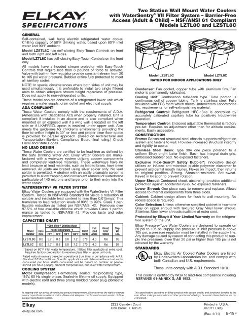
SPECIFICATIONS<br />
Two Station Wall Mount Water Coolers<br />
with WaterSentry ® VII Filter System – Barrier-Free<br />
Access (Adult & Child) – NSF/ANSI 61 Compliant<br />
Models LZTL8C and LZSTL8C<br />
GENERAL<br />
Self-contained, wall hung electric refrigerated water cooler.<br />
Chilling capacity of 50°F drinking water, based upon 80°F inlet<br />
water and 90°F ambient.<br />
Model LZSTL8C has self-closing Easy-Touch Controls on front<br />
and both right and left sides.<br />
Model LZTL8C has self-closing Easy-Touch Controls on the front<br />
only.<br />
All models have a hooded stream projector with Easy-Touch<br />
Controls that require less than 3 pounds of force to activate.<br />
Valve with built-in flow regulator provide constant stream from 20<br />
to 105 psi water pressure. Bubbler orifice fully protected to meet<br />
all sanitary codes.<br />
NOTE: In special circumstances where both sides of unit may be<br />
used simultaneously it is preferable to install two single filtered<br />
units to obtain adequate stream height regardless of pressure.<br />
Does not apply to non-refrigerated units.<br />
These model coolers consists of a refrigerated lower unit which<br />
requires a water supply, drain outlet and electrical supply.<br />
ADA COMPLIANT<br />
These Water Coolers comply with the requirements of A.D.A.<br />
(Americans with Disabilities Act) when properly installed. Unit is<br />
compliant if installed in an alcove and is also compliant when<br />
mounted on an exposed wall if a wing wall is located on the left<br />
side or if LKAPREZL apron is installed under upper unit. Also<br />
meets the guidelines for children’s environments providing the<br />
floor to orifice height is 30" or less and proper clear floor space<br />
is provided for parallel approach. (Based on Architectural and<br />
Transportation Barriers Compliance Board final ruling.) Check<br />
Local and State Codes.<br />
NO LEAD DESIGN<br />
These Water Coolers are certified to be lead-free as defined by<br />
the Safe Drinking Water Act. Elkay Water Coolers are manufactured<br />
with a waterway system utilizing copper components<br />
and completely lead-free materials. These waterways have no<br />
lead because all lead materials, such as leaded brass, have been<br />
removed. All joints are brazed using silver solder only. No lead<br />
solder is permitted. A strainer with an easily cleanable screen is<br />
provided to allow trapping and convenient removal of waterborne<br />
particulate of 140 microns and larger prior to their entry into the<br />
water cooler.<br />
WATERSENTRY ® VII FILTER SYSTEM<br />
Elkay Water Coolers are equipped with the WaterSentry VII Filter<br />
System. Tested to NSF/ANSI Standard 53 yields a reduction of<br />
soluble and insoluble lead content to less than 0.015mg/l. This<br />
translates to lead reduction levels of 93% to 99%. Class 1 particulate<br />
reduction as tested per NSF/ANSI 42. Removes over<br />
97.5% of free available chlorine which provides Class 1 performance<br />
as tested to NSF/ANSI 42. Provides taste and odor<br />
improvement.<br />
CAPACITIES CHART<br />
**GPH of 50°F Drinking Water<br />
Full Glass† Ship.<br />
Model Base<br />
Room Temperature °F<br />
Rated Load Filler Wt.<br />
Number Rate 70°F 80°F 90°F 100°F Watts Amps Option Lbs.<br />
LZSTL8C 8.0 9.7 8.8 8.0 7.2 370 4.0 Yes 92<br />
LZTL8C 8.0 9.7 8.8 8.0 7.2 370 4.0 Yes 92<br />
**Based on 80°F inlet water temperature. †Glass filler available at extra cost.<br />
Requires factory preparation to receive glass filler – upper unit only.<br />
Rated watts shown are based on operational (run) time, in compliance with A.R.I.<br />
Standard 1010 conditions. Specific applications will determine the actual watts<br />
consumed per hour. Watts consumed will be based on number of people<br />
served per hour (usage), ambient temperatures, and inlet water temperature.<br />
COOLING SYSTEM<br />
Motor Compressor: Hermetically sealed, reciprocating type,<br />
115V, 60 Hz single phase. Sealed-in lifetime oil supply. Equipped<br />
with electric cord and three prong molded rubber plug (domestic<br />
models).<br />
Model LZSTL8C<br />
Model LZTL8C<br />
RATED FOR INDOOR APPLICATIONS ONLY<br />
Condenser: Fan cooled, copper tube with aluminum fins. Fan<br />
motor is permanently lubricated.<br />
Cooling Unit: Combination tube-tank type. Tube portion is<br />
continuous coil of copper tubing. Tank is stainless steel. Fully<br />
insulated with EPS foam which meets Underwriters Laboratories<br />
Inc. requirements for self-extinguishing material.<br />
Refrigerant Control: Refrigerant HFC-134a is controlled by<br />
accurately calibrated capillary tube for positively trouble-free<br />
operation.<br />
Temperature Control: Enclosed adjustable thermostat is factory<br />
pre-set. Requires no adjustment other than for altitude requirements.<br />
Easily accessible.<br />
CONSTRUCTION<br />
Frame: Galvanized structural steel chassis supports refrigeration<br />
system and fastens to wall. Provides increased structural integrity<br />
and rigidity to cooler.<br />
Stainless Steel Basin: Type 304 one piece polished to a<br />
uniform Elkay bright luster finish. Basin has integral drain grid,<br />
embossed bubbler pad. No exposed fasteners.<br />
Exclusive Flexi-Guard ® Safety Bubbler*: Innovative design<br />
utilizes an infused anti-microbial pliable polyester elastomer to<br />
prevent accidental mouth injuries. Flexes on impact, then returns<br />
to original position. Strong. Abrasion-resistant. Anti-sweat.<br />
Keyed in loca tion to prevent rotation.<br />
Upper Shroud: Contoured shock-absorbing, provides additional<br />
protection against accidental injury. No exposed fasteners.<br />
Lower Shroud: One piece easy to remove and replace. Allows<br />
access to internal components from three sides.<br />
Cabinet: Cabinet design allows for flush to wall mounting. No<br />
recess space is required.<br />
Color Selection: Unless otherwise specified cabinet is two-tone<br />
Gray on upper shroud with textured Gray Vinyl lower shroud.<br />
Stainless Steel lower shrouds available at extra cost.<br />
Protected by Elkay’s 5 Year Limited Warranty on the refrigeration<br />
system of the unit.<br />
Elkay Pressure-Type Water Coolers are designed to operate on<br />
20 psi to 105 psi supply line pressure. If inlet pressure is above<br />
105 psi, a pressure regulator must be installed in the supply line.<br />
Any damage caused by reason of connecting this product to supply<br />
line pressures lower than 20 psi or higher than 105 psi is not<br />
covered by the warranty.<br />
STANDARDS<br />
Elkay Electric Air Cooled Water Coolers are listed<br />
by Underwriters Laboratories Inc. and comply with<br />
both Canadian and U.S. requirements.<br />
These units comply with A.R.I. Standard 1010.<br />
This cooler is certified by WQA to lead-free compliance including<br />
NSF/ANSI 61-ANNEX G, AB 1953.<br />
In keeping with our policy of continuing product improvement, Elkay reserves the right to change<br />
product <strong>specifications</strong> without notice. Please visit elkayusa.com for most current version of Elkay<br />
product specification sheets.<br />
Elkay<br />
elkayusa.com<br />
2222 Camden Court<br />
Oak Brook, IL 60523<br />
This specification describes an Elkay product with design, quality and functional benefits to the<br />
user. When making a comparison of other producers’ offerings, be certain these features are not<br />
overlooked.<br />
Printed in U.S.A.<br />
©2011 Elkay<br />
(Rev. 4/11) 8-19F
INSURE PROPER VENTILATION BY MAINTAINING 6" (152mm) MINIMUM CLEARANCE FROM CABINET LOUVERS TO WALL.<br />
F = 7/16 BOLT HOLES FOR FASTENING UNIT TO WALL<br />
D = ELECTRICAL SUPPLY (3) WIRE RECESSED BOX DUPLEX OUTLET<br />
C = 1-1/2 TRAP NOT FURNISHED<br />
FROM WALL<br />
B = RECOMMENDED LOCATION OUT IN. 2 STUB DRAIN DRAIN. NOMINAL 1-1/2" ACCOMODATE TO OUTLET WASTE FOR<br />
OUT MAXIMUM (76mm) 3" WALL.<br />
FROM<br />
WATER RECOMMENDED = A TUBE.<br />
COPPER UNPLATED O.D. 3/8 ACCEPT TO FURNISHED (NOT VALVE SHUT-OFF LOCATION. SUPPLY<br />
LEGEND<br />
VIEW<br />
SIDE VIEW<br />
FRONT<br />
Two Station Wall Mount Water Coolers<br />
with WaterSentry ® VII Filter System – Barrier-Free<br />
Access (Adult & Child) – NSF/ANSI 61 Compliant<br />
Models LZTL8C and LZSTL8C<br />
ROUGH-IN DIMENSIONS<br />
WaterSentry ® VII Filter System<br />
OPERATION OF QUICK CONNECT FITTINGS<br />
SIMPLY PUSH IN<br />
TUBE TO ATTACH<br />
TUBE IS SECURED<br />
IN POSITION<br />
PUSH IN COLLET<br />
TO RELEASE TUBE<br />
IMPORTANT!<br />
INSTALLER PLEASE NOTE:<br />
This water cooler has been designed and built to provide water to the<br />
user which has not been altered by materials in the cooler waterways.<br />
The grounding of electrical equipment such as telephone, computers,<br />
etc., to water lines is a common procedure. This grounding may be<br />
in the building but may also occur away from the building. This grounding<br />
can cause electrical feedback into a water cooler creating an electrolysis<br />
which creates a metallic taste or causes an increase in the metal content<br />
of the water. This condition is avoidable by installing the cooler using the<br />
proper materials as shown below.<br />
NOTICE<br />
This water cooler must be connected to the water supply using a dielectric<br />
coupling. The cooler is furnished with a non-metallic strainer<br />
which meets this requirement.<br />
The drain trap which is provided by the installer should also be plastic to<br />
completely isolate the cooler from the building plumbing system.<br />
A B C<br />
PUSHING TUBE IN BEFORE<br />
PULLING IT OUT HELPS TO<br />
RELEASE TUBE<br />
FRONT VIEW<br />
RATED FOR INDOOR APPLICATIONS ONLY<br />
SIDE VIEW<br />
LEGEND<br />
A = RECOMMENDED WATER SUPPLY LOCATION. SHUT-OFF VALVE (NOT FURNISHED TO ACCEPT 3/8 O.D. UNPLATED COPPER TUBE.<br />
3" (76mm) MAXIMUM OUT FROM WALL.<br />
B = RECOMMENDED LOCATION FOR WASTE OUTLET TO ACCOMODATE 1-1/2" NOMINAL DRAIN. DRAIN STUB 2 IN. OUT FROM WALL<br />
C = 1-1/2 TRAP NOT FURNISHED<br />
D = ELECTRICAL SUPPLY (3) WIRE RECESSED BOX DUPLEX OUTLET<br />
F = 7/16 BOLT HOLES FOR FASTENING UNIT TO WALL<br />
INSURE PROPER VENTILATION BY MAINTAINING 6" (152mm) MINIMUM CLEARANCE FROM CABINET LOUVERS TO WALL.<br />
Elkay<br />
8-19F (Rev. 4/11)<br />
2222 Camden Court<br />
Oak Brook, IL 60523<br />
elkayusa.com<br />
Printed in U.S.A.<br />
©2011 Elkay
PRODUCT FEATURES<br />
• Complete filtered cooler and bottle filling<br />
station in a consolidated space saving ADAcompliant<br />
design<br />
• Sanitary, no-touch, sensor activation with<br />
automatic 30-second shut-off timer<br />
• WaterSentry ® Plus 3000 gallon filter included<br />
• Flexi-Guard ® StreamSaver Bubbler<br />
• Silver Ion anti-microbial protection<br />
• Quick fill rate is 1.1 gpm for refrigerated units<br />
and 1.5 gpm for non-refrigerated units<br />
• Laminar flow provides minimal splash<br />
• Real drain system eliminates standing water<br />
• Visual user interface display includes:<br />
• Filter Monitor indicating when replacement<br />
is necessary<br />
• Green Ticker counting the quantity of 16<br />
oz. bottles saved from the landfill for nonrefrigerated<br />
units and 12 oz. bottles for<br />
refrigerated units<br />
Unit shall provide 8.0 gph of 50 0 F water at 90 0 F<br />
ambient and 80 0 F inlet water. Bottle filling unit<br />
shall include an electronic sensor for no-touch<br />
activation with an automatic 30-second shut-off<br />
timer. Shall provide 1.1-1.5* gpm flow rate with<br />
laminar flow to minimize splashing. Shall include<br />
antimicrobial protected plastic components to<br />
prevent mold and mildew. Cooler unit shall have<br />
pushbar activation and water-efficient Stream-<br />
Saver bubbler. Shall include the WaterSentry®<br />
Plus filter, certified to NSF/ANSI 42 and 53 for<br />
lead reduction, with visual monitor to indicate<br />
when replacement is necessary. Bottle Filling<br />
unit shall meet ADA guidelines for parallel approach.<br />
Cooler shall meet ADA guidelines for<br />
frontal or parallel approach. Unit shall be leadfree<br />
design which meets Safe Drinking Water Act<br />
and is certified to NSF/ANSI 61 and California<br />
AB1953. Unit shall be certified to UL399 and<br />
CAN/CSA 22.2 No. 120.<br />
EZH2O T M System<br />
Cooler/Bottle Filling Station<br />
Models LZS8WS and LZSTL(R)8WS<br />
IMAGES<br />
Model LZS8WSLK shown.<br />
Includes Single Filtered<br />
Cooler with Bottle Filling<br />
Station.<br />
¨ Vandal-resistant StreamSaver Bubbler<br />
¨ 51300C Replacement filter<br />
Model LZSTL8WSLK<br />
shown. Includes Bi-Level<br />
Filtered Cooler with<br />
Bottle Filling Station<br />
¨ 51300C_3PK Replacement filter 3-pack<br />
¨ 36292C Receptacle Adaptor Plug<br />
OPTIONAL ACCESSORIES<br />
Ideal for use in:<br />
• Educational facilities<br />
• Healthcare facilities<br />
• Sport and fitness centers<br />
• Airports<br />
• Office buildings<br />
• Other commercial buildings<br />
SUGGESTED SPECIFICATION<br />
*Fill rate may vary slightly depending on existing refrigeration systems in the field<br />
2222 Camden Court<br />
Oak Brook, IL 60523<br />
Phone: 630-572-3192<br />
Web: Elkayusa.com<br />
APPLICATIONS<br />
Third Party Certified to:<br />
• UL399 and CAN/CSA 22.2 No. 120<br />
• Lead-free compliance including<br />
NSF/ANSI 61 and CA AB1953<br />
In keeping with our policy of continuing product improvement, Elkay reserves the right to change <strong>specifications</strong><br />
without notice.<br />
Please visit elkayusa.com for the most current version.<br />
© 2010 Elkay<br />
14-57C (4/2010)
Job Name: ________________________________________<br />
Date: __________________________________ Qty: ______<br />
Page 2<br />
EZH2O is designed to fit on an EZ Cooler which is properly<br />
installed per the EZ Spec Sheet rough-in design.<br />
*Rated for Indoor Use Only<br />
ELKAY®<br />
ROUGH-IN DIMENSIONS<br />
Single Cooler Installation<br />
Bi-Level Cooler Installation<br />
Installation Notes:<br />
• Unit will mount on bracket attached to wall by 6 holes (as shown above)<br />
• Water and electrical will connect thru a hole punched into basin.<br />
Basin will be pre-punched.<br />
• Refer to page 3 for single EZ rough-in.<br />
• Refer to page 4 for bi-level EZ rough-in.<br />
Contact Info (Name, Phone, Email): _____________________<br />
__________________________________________________<br />
__________________________________________________<br />
Approval for Manufacture Signature and Date:<br />
__________________________________________________<br />
Specifications and measurements are subject to change<br />
without notification.<br />
Please visit elkayusa.com for most current version.<br />
2222 Camden Court<br />
Oak Brook, IL 60523<br />
Phone: 630-572-3192<br />
Web: Elkayusa.com<br />
Models LZS8WS<br />
and LZSTL8WS
Page 3<br />
*Rated for Indoor Use Only<br />
ELKAY®<br />
ROUGH-IN DIMENSIONS<br />
*Reduce Height By 3” For Installation Of Children’s ADA Cooler<br />
LEGEND:<br />
A = Recommended Water Supply Location 3/8 O.D. Unplated Copper Tube Connect Stub With Shut-Off (By Others) - 3” (76mm)<br />
Maximum Out From Wall.<br />
B = Recommended Location For Waste Outlet To Accommodate 1-1/2” Nominal Drain. Drain Stub 2” Out From Wall.<br />
C = 1-1/2” Trap (Not Furnished)<br />
D = Electrical Supply (3) Wire Recessed Box Duplex Outlet<br />
E = Insure proper ventilation by maintaining 6” (152mm) minimum clearance from cabinet louvers to wall.<br />
F = 7/16” Bolt Holes For Fastening Unit To Wall<br />
Specifications and measurements are subject to change<br />
without notification.<br />
Please visit elkayusa.com for most current version.<br />
2222 Camden Court<br />
Oak Brook, IL 60523<br />
Phone: 630-572-3192<br />
Web: Elkayusa.com<br />
EZ Style Single Level<br />
Cooler Installation
*Reduce Height By 3” For Installation Of Children’s ADA Cooler<br />
LEGEND:<br />
A = Recommended Water Supply Location 3/8 O.D. Unplated Copper Tube Connect Stub With Shut-Off (By Others) - 3” (76mm)<br />
Maximum Out From Wall.<br />
B = Recommended Location For Waste Outlet To Accommodate 1-1/2” Nominal Drain. Drain Stub 2” Out From Wall.<br />
C = 1-1/2” Trap (Not Furnished)<br />
D = Electrical Supply (3) Wire Recessed Box Duplex Outlet<br />
E = Insure proper ventilation by maintaining 6” (152mm) minimum clearance from cabinet louvers to wall.<br />
F = 7/16” Bolt Holes For Fastening Unit To Wall<br />
Page 4<br />
*Rated for Indoor Use Only<br />
ELKAY®<br />
ROUGH-IN DIMENSIONS<br />
Specifications and measurements are subject to change<br />
without notification.<br />
Please visit elkayusa.com for most current version.<br />
2222 Camden Court<br />
Oak Brook, IL 60523<br />
Phone: 630-572-3192<br />
Web: Elkayusa.com<br />
EZ Style Bi-Level<br />
Cooler Installation
®<br />
Z415B<br />
BODY ASSEMBLY<br />
W/ "TYPE B" STRAINER<br />
SPECIFICATION SHEET<br />
TAG _______<br />
Dimensional Data (inches and [ mm ]) are Subject to Manufacturing Tolerances and Change Without Notice<br />
Dimensions In Inches<br />
ENGINEERING SPECIFICATION: ZURN ZN415B<br />
Floor and shower drain, Dura-Coated cast iron body with bottom outlet, combination invertible membrane clamp and adjustable collar<br />
with seepage slots and "TYPE B" polished nickel bronze, light-duty strainer.<br />
OPTIONS (Check/specify appropriate options)<br />
PIPE SIZE (Specify size/type) OUTLET 'E' BODY HT. DIM.<br />
2 thru 4 [51 thru 102] _____ IC Inside Caulk 3-7/8 [98]<br />
2 thru 4 [51 thru 102] _____ IG Inside Gasket 3-7/8 [98]<br />
2 [51] _____ IP Threaded 2-3/8 [60]<br />
3 [76] _____ IP Threaded 2-5/8 [67]<br />
4 [102] _____ IP Threaded 2-7/8 [73]<br />
6 [152] _____ IP Threaded 2-3/4 [70]<br />
2 thru 4 [51 thru 102] _____ NH No-Hub 3-7/8 [98]<br />
2 thru 4 [51 thru 102] _____ NL Neo-Loc 3-3/4 [95]<br />
PREFIXES<br />
___ ZB D.C.C.I. Body Assembly w/ Polished Bronze Top<br />
___ ZN D.C.C.I. Body Assembly w/ Polished Nickel Bronze Top*<br />
SUFFIXES<br />
___ -AA All Acid Resisting Epoxy<br />
___ -SR Stabilizer Ring<br />
___ -AR Acid Resisting Epoxy Coated Cast Iron<br />
___ -TC Neo-Loc Test Cap Gasket (2-4 [51-102] NL Outlet Only)<br />
___ -C Clamp Collar for -90 Side Outlet Body<br />
___ -U 1 - 3 [25 - 76] High Extension Adapter<br />
___ -CP Chrome-Plated Bronze Top<br />
___ -DC Debris Cover (Field Assembled)<br />
___ -DP Decorative Polished Top<br />
___ -V<br />
___ -VP<br />
___ -W<br />
Backwater Valve<br />
Vandal-Proof Secured Top<br />
Winter Closure Plug<br />
___ -EF 3/8 [16] Extension Frame<br />
___ -Y Sediment Bucket<br />
___ -G Galvanized Cast Iron<br />
___ -4 4 [102] Diameter Funnel (Z328)<br />
___ -HD Heavy-Duty Slotted Grate (ZN 5 [127] & 6 [152] Sizes Only)<br />
___ -OF Oval Funnel (Z329-7) (6 - 10 [152 - 254] Strainers Only)<br />
___ -P Trap Primer Connection (Specify 1/2 [13] or 3/4 [19])<br />
___ -SA Stabilizer Assembly (See Z1035)<br />
___ -SQ Stabilizer Q-Deck (See Z1035-Q)<br />
*REGULARLY FURNISHED UNLESS OTHERWISE SPECIFIED<br />
___ -18<br />
___ -90<br />
REV. P<br />
Approx.<br />
Wt. Lbs.<br />
[kg]<br />
Leveling Ring (See Z400-18)<br />
90° Threaded Side Outlet Body Assembly<br />
(2 [51], 3 [76] Only)<br />
DWG. NO. 58789<br />
Strainer<br />
Open Area<br />
Sq. In. [cm 2 ]<br />
A B Strainer<br />
K<br />
K'<br />
Pipe Size Dia. Min. Max. Min. Max.<br />
2-3 [51-76] 5 [127] 1 [25] 1-1/2 [38] 1-3/32 [28] 2-1/4 [57] 11 [5] 8 [52]<br />
2-3-4 [51-76-102] 6 [152] 1 [25] 1-25/32 [45] 1-13/32 [36] 2-17/32 [64] 13 [6] 9 [58]<br />
2-3-4 [51-76-102] 7 [178] 1 [25] 2-1/8 [54] 1-23/32 [44] 2-7/8 [73] 14 [6] 12 [77]<br />
3-4 [76-102] 8 [203] 1-5/32 [30] 2-1/8 [54] 1-3/4 [44] 2-7/8 [73] 16 [7] 18 [116]<br />
6 [152] 8 [203] 1-5/32 [30] 2-1/8 [54] 1-3/4 [44] 2-7/8 [73] 18 [8] 18 [116]<br />
6 [152] 10 [254] 1-7/16 [37] 2-1/2 [64] 2 [51] 3-1/4 [83] 22 [10] 26 [168]<br />
DATE: 06/20/11 C.N. NO. 121440<br />
PRODUCT NO. Z415B<br />
ZURN INDUSTRIES, LLC ♦ SPECIFICATION DRAINAGE OPERATION ♦ 1801 Pittsburgh Ave. ♦ Erie, PA 16514<br />
Phone: 814/455-0921 ♦ Fax: 814/454-7929 ♦ World Wide Web: www.zurn.com<br />
In Canada: ZURN INDUSTRIES LIMITED ♦ 3544 Nashua Drive ♦ Mississauga, Ontario L4V1L2 ♦ Phone: 905/405-8272 Fax: 905/405-1292
Features<br />
• Vitreous china<br />
• Wall-mount<br />
• With hanger<br />
• With overflow<br />
• Drilled for concealed arm carrier<br />
• Optional soap dispenser hole on left (-L) or right (-R)<br />
• 8″ (203 mm) centers, 4″ (102 mm), centers or single<br />
hole<br />
• 21-1/4″ (540 mm) x 18-1/8″ (460 mm)<br />
Codes/Standards Applicable<br />
Specified model meets or exceeds the following:<br />
• ADA<br />
• ICC/ANSI A117.1<br />
• CSA B651<br />
• OBC<br />
• ASME A112.19.2/CSA B45.1<br />
Specified Model<br />
WALL-MOUNT LAVATORY<br />
K-2005<br />
ALSO K-2006, K-2007<br />
ADA<br />
KINGSTONTM<br />
CSA B651<br />
OBC<br />
Colors/Finishes<br />
• 0: White<br />
• Other: Refer to Price Book for additional colors/finishes<br />
Accessories<br />
• CP: Polished Chrome<br />
• Other: Refer to Price Book for additional colors/finishes<br />
Model Description Colors/Finishes<br />
K-2005 Lavatory with 4″ (102 mm) centers less soap dispenser hole ❑ 0 ❑ Other_____<br />
K-2005-L Lavatory with 4″ (102 mm) centers with soap dispenser hole on left ❑ 0 ❑ Other_____<br />
K-2005-R Lavatory with 4″ (102 mm) centers with soap dispenser hole on right ❑ 0 ❑ Other_____<br />
K-2006 Lavatory with 8″ (203 mm) centers less soap dispenser hole ❑ 0 ❑ Other_____<br />
K-2007 Lavatory with single hole less soap dispenser hole ❑ 0 ❑ Other_____<br />
K-2007-L Lavatory with single hole with soap dispenser hole on left ❑ 0 ❑ Other_____<br />
K-2007-R Lavatory with single hole with soap dispenser hole on right ❑ 0 ❑ Other_____<br />
Recommended Accessories<br />
K-8998 P-Trap ❑ CP ❑ Other_____<br />
Product Specification<br />
Lavatory shall be made of vitreous china. The lavatory shall be 21-1/4″ (540 mm) in length and 18-1/8″ (460 mm) in width.<br />
Lavatory shall be wall-mounted with hangers. Lavatory shall have 8″ (203 mm) centers (K-2006), 4″ (102 mm) centers (K-2005),<br />
or single hole (K-2007). Lavatory shall have overflow. Lavatory shall be drilled for concealed arm carrier. Lavatory shall have<br />
optional soap dispenser hole left (-L) or right (-R). Lavatory shall be Kohler Model K-______-______-______.<br />
Page 1 of 2<br />
116611-4-CL<br />
USA/Canada: 1-800-4KOHLER<br />
(1-800-456-4537)<br />
www.kohler.com
KINGSTONTM<br />
Technical Information<br />
Fixture*:<br />
Basin area 16″ (406 mm) x 10″ (254 mm)<br />
Water depth 3-1/8″ (79 mm)<br />
Drain hole Ø 1-3/4″ (44 mm)<br />
* Approximate measurements for comparison only.<br />
Installation Notes<br />
Install this product according to the installation guide.<br />
Will comply with ADA when installed per Section 606<br />
Lavatories of the Act.<br />
Will comply with CSA B651 when installed per Clause 4.3.3<br />
of the standard.<br />
Will comply with OBC when installed per Clause 3.8.3.11.<br />
Holes K-2005 K-2006 K-2007<br />
Spout Ø 1-1/4″<br />
(32 mm)<br />
Ø 1-3/8″<br />
(35 mm)<br />
Ø 1-3/8″<br />
(35 mm)<br />
Faucet Ø 1-1/4″<br />
(32 mm)<br />
Ø 1-3/8″<br />
(35 mm)<br />
Soap<br />
dispenser<br />
Ø 1-1/4″<br />
(32 mm)<br />
Ø 1-1/4″<br />
(32 mm)<br />
Included components:<br />
Hanger 64839<br />
Concealed Arm<br />
Hole Location<br />
K-2006<br />
1/2" (13 mm) 2" (51 mm)<br />
4" (102 mm) 3-3/4" (95 mm)<br />
4" (102 mm)<br />
Faucet Holes<br />
13-3/4"<br />
(349 mm)<br />
8-1/2"<br />
(216 mm)<br />
Ø 1-1/4" (32 mm)<br />
Leveling Screw<br />
Hole<br />
33<br />
(845 mm)<br />
8-3/8"<br />
(213 mm)<br />
Leveling<br />
Screw Slot<br />
18-1/8"<br />
(460 mm)<br />
17-1/4" (438 mm) Ø 1-1/4" (32 mm)<br />
Locking Device<br />
21-1/4" (540 mm) Hole<br />
8-1/4" (210 mm)<br />
12"<br />
(305 mm)<br />
5" (127 mm)<br />
3/8"<br />
Hot<br />
29-1/8"<br />
(740 mm)<br />
1-1/4" OD<br />
4" (102 mm)<br />
Standard Installation<br />
4-3/8" 7-1/4"<br />
(111 mm) (184 mm)<br />
3/8" Cold<br />
12-7/8"<br />
(327 mm)<br />
34"<br />
(864 mm)<br />
Max<br />
27"<br />
(686 mm)<br />
Min<br />
4-1/4"<br />
(108 mm)<br />
31"<br />
(787 mm)<br />
4-1/4"<br />
(108 mm)<br />
18-1/8" (460 mm)<br />
8"<br />
(203 mm)<br />
Min<br />
9"<br />
(229 mm)<br />
Min<br />
Recommended ADA Installation<br />
K-2005<br />
-L 4" (102 mm) -R<br />
4-1/2" (114 mm)<br />
K-2007<br />
4-3/8" (111 mm)<br />
-L -R<br />
9"<br />
(229 mm)<br />
6"<br />
(152 mm)<br />
Max<br />
3-3/4"<br />
(95 mm)<br />
3-3/4"<br />
(95 mm)<br />
KINGSTONTM WALL-MOUNT LAVATORY<br />
Page2of2<br />
116611-4-CL<br />
Product Diagram
Battery Powered Hand Washing Faucet<br />
EBF-85<br />
u<br />
Description<br />
Battery Powered, Sensor Activated Electronic Hand Washing Faucet for tempered or hot/cold<br />
water operation.<br />
u<br />
Flow Rate<br />
£0.5 gpm/1.9 Lpm Vandal Resistant Spray Head<br />
(See Accessories for other Spray Head options)<br />
u<br />
Specifications<br />
ADA Compliant, Battery Powered, Sensor Activated, Chrome Plated Brass Hand Washing Faucet<br />
with the following features:<br />
• Splash-proof Circuit Control Module<br />
• Fiber Optic, Automatic, Self-adaptive Sensing<br />
• Isolated Latching Solenoid Operator, isolates magnetic components from water contact<br />
• Audible Tone Low Battery Indicator<br />
• Serviceable Filtered Solenoid Valve<br />
• Bak-Chek ® Tee for Hot/Cold Supply<br />
• Trim Plate with Anti-Rotation Pin (specify 4” or 8”)<br />
• Vandal Resistant Spray Head with Pressure Compensating Flow Control<br />
• Polypropylene Optic Cable Protection<br />
• Includes four (4) C-size Alkaline Batteries<br />
u<br />
u<br />
Variations<br />
(Add suffix to Model Number for inclusion with Faucet)<br />
• Trim Plate (must be specified)<br />
£ -4 Trim Plate for 4” Centerset Sink<br />
£ -8 Trim Plate for 8” Centerset Sink<br />
• Temperature Mixing Valves (optional)<br />
£ ADM Above Deck Mechanical Mixing Valve<br />
£ BDM Below Deck Mechanical Mixing Valve<br />
£ BDT Below Deck Thermostatic Mixing Valve<br />
Bak-Chek ® Tee not required or provided when a Temperature Mixing Valve is included with the<br />
faucet.<br />
Consult Factory for Finish Variations<br />
Accessories (Specify separately)<br />
• Vandal Resistant Spray Heads<br />
£ ETF-1027-A 2.2 gpm/8.3 Lpm Laminar Flow Spray Head<br />
(recommended for medical applications)<br />
£ ETF-1022-A 2.2 gpm/8.3 Lpm Aerator<br />
• Grid Strainer<br />
£ ETF-460-A Chrome Plated Brass Grid Strainer w/1¼” Outlet Tube<br />
See OPTIMA Accessories Section of the Sloan Catalog for a complete listing of OPTIMA Faucet<br />
Accessories and Variations.<br />
u<br />
u<br />
u<br />
u<br />
u<br />
u<br />
ADA Compliant<br />
Automatic<br />
The Sloan OPTIMA Plus ® EBF-85 Battery Powered, Electronic Hand<br />
Washing Faucet operates by means of an adaptive infrared sensor that<br />
is linked to the faucet by a fiber optic cable. Once the user’s hands<br />
enter the sensor’s effective range, the Solenoid activates the water flow.<br />
Tempered water flows from the Faucet until hands are moved away.<br />
The Faucet then automatically shuts off.<br />
Hygienic<br />
The ultimate in sanitary protection — there are no handles to turn or<br />
buttons to push. Helps to control the spread of infectious diseases.<br />
Economical<br />
Automatic operation provides water usage savings over other faucet<br />
devices. Reduces maintenance and operation costs. Self-adaptive<br />
Range Adjustment makes installation quick and easy. Battery operation<br />
ideal for Retrofit installations.<br />
Warranty<br />
3 year (limited)<br />
Compliant to:<br />
ASME A112.18.1-2005/CSA B125.1-05<br />
ISO/IEC 17025<br />
This product may<br />
contribute to<br />
LEED credits.<br />
See details on LEED<br />
calculation worksheet.<br />
This space for Architect/Engineer approval<br />
Job Name<br />
Model Specified<br />
Date<br />
Quantity<br />
Variations Specified<br />
Customer/Wholesaler<br />
Contractor<br />
Architect<br />
Optima Plus EBF-85 S.S. — Rev. 2 (09/10)<br />
The information contained in this document is subject to change without notice.
EBF-85<br />
FAUCET DIMENSIONS<br />
(Shown with 4” Trim Plate)<br />
u<br />
u<br />
Description<br />
Battery Powered, Sensor Activated Electronic Hand Washing Faucet for tempered or<br />
hot/cold water operation.<br />
Flow Rate<br />
£0.5 gpm/1.9 Lpm Vandal Resistant Spray Head<br />
(See Accessories for other Spray Head options)<br />
ELECTRICAL SPECIFICATIONS<br />
u<br />
u<br />
Control Circuit<br />
6 VDC — Operates on four (4)<br />
alkaline C-size batteries. Self-adaptive<br />
Range Adjustment, Audible<br />
Troubleshooting and Low Battery<br />
Indicator. Fiber Optic Cable between<br />
Electronic Module and Faucet keeps<br />
all electronic signals below the sink.<br />
Battery Life<br />
2 years at 8,000 cycles/month<br />
u<br />
u<br />
OPTIMA ® Sensor Range<br />
Nominal: 4”- 5” (102 mm - 127 mm)<br />
Self-adaptive Zone: 2” - 8”<br />
(51 mm - 203 mm) — Faucet selfadjustment<br />
range within this zone<br />
dependent upon depth and reflectivity of<br />
basin.<br />
Solenoid Valve<br />
Low Energy Latching Solenoid with Selfcleaning<br />
By-pass and Integral Clean Out<br />
Strainer Filter.<br />
u<br />
u<br />
Time Out Adjustment Settings<br />
30 seconds — The Faucet Time out Setting determines the maximum time the<br />
faucet will run upon continuous detection. The EBF-85 is factory set at the 30<br />
second time out. Consult factory for time out settings to meet individual<br />
application requirements.<br />
Maximum Distance Control Module may be Installed from Spout<br />
30” (762 mm)<br />
OPERATION<br />
1. Continuous, invisible light<br />
beams are emitted from the<br />
OPTIMA ® Sensor. Fiber optic<br />
cables transmit the light from<br />
the circuit to the spout.<br />
2. The faucet is activated by<br />
placing hands beneath the<br />
spray head, thus activating the<br />
Solenoid Valve. Tempered<br />
water flows for as long as<br />
hands continue to stay within<br />
the Sensor’s range (30 second<br />
automatic shut off).<br />
3. When hands are removed,<br />
the water flow automatically<br />
stops. The faucet is then<br />
ready for the next user.<br />
EBF-85 Faucet with Bak-Chek ® Tee<br />
for Hot and Cold Water Supply<br />
(shown with 4” trim plate)<br />
EBF-85 Faucet with ADM Variation Mixing<br />
Valve for Hot and Cold Water Supply<br />
(shown with 8” trim plate)<br />
EBF-85 Faucet with BDM and BDT Variation Mixing<br />
Valves for Hot and Cold Water Supply<br />
(shown with 4” trim plate)<br />
SLOAN VALVE COMPANY • 10500 SEYMOUR AVENUE • FRANKLIN PARK, IL 60131<br />
Phone: 1-800-982-5839 or 1-847-671-4300 • Fax: 1-800-447-8329 or 1-847-671-4380 • www.sloanvalve.com<br />
Copyright © 2010 Sloan Valve Company Optima Plus EBF-85 S.S. — Rev. 2 (09/10)
Features<br />
• Vitreous china<br />
• Drop-in<br />
• Single-hole<br />
• ADA compliant when installed in a 21″ (533 mm)<br />
minimum depth countertop<br />
• Optional soap dispenser hole on left (-L) or right (-R)<br />
• With or without overflow<br />
• 20-1/4″ (514 mm) x 17-1/2″ (445 mm)<br />
Codes/Standards Applicable<br />
Specified model meets or exceeds the following:<br />
• ADA<br />
• ICC/ANSI A117.1<br />
• CSA B651<br />
• OBC<br />
• ASME A112.19.2/CSA B45.1<br />
Specified Model<br />
COUNTERTOP BATHROOM SINK<br />
K-2196<br />
ADA<br />
CSA B651<br />
OBC<br />
Colors/Finishes<br />
• 0: White<br />
• Other: Refer to Price Book for additional colors/finishes<br />
Accessories<br />
• CP: Polished Chrome<br />
PENNINGTON ®<br />
Model Description Colors/Finishes<br />
K-2196-1N Single-hole drilling; less overflow ❑ 0 ❑ Other_____<br />
K-2196-1K Single-hole drilling; less overflow; with soap dispenser hole on right ❑ 0 ❑ Other_____<br />
K-2196-1F Single-hole drilling; less overflow; with soap dispenser hole on left ❑ 0 ❑ Other_____<br />
K-2196-1 Single-hole drilling; with overflow; less soap dispenser hole ❑ 0 ❑ Other_____<br />
K-2196-1L Single-hole drilling; with overflow; with soap dispenser hole on left ❑ 0 ❑ Other_____<br />
K-2196-1R Single-hole drilling; with overflow; with soap dispenser hole on right ❑ 0 ❑ Other_____<br />
Recommended Accessories<br />
K-8998 P-Trap ❑ CP<br />
Product Specification<br />
The drop-in bathroom sink shall be made of vitreous china. Bathroom sink shall be 20-1/4″ (514 mm) in length, and 17-1/2″ (445<br />
mm) in width. Bathroom sink shall have single-hole drilling (-1). Bathroom sink shall be ADA compliant when installed in a 21″<br />
(533 mm) minimum depth countertop. Bathroom sink shall feature optional soap dispenser hole (-L, left or -R, right). Bathroom<br />
sink shall be Kohler Model K-2196-_______-______.<br />
Page 1 of 2<br />
113805-4-DG<br />
USA/Canada: 1-800-4KOHLER<br />
(1-800-456-4537)<br />
www.kohler.com
PENNINGTON ®<br />
Technical Information<br />
Fixture*:<br />
Basin area 16″ (406 mm) x 11″ (279 mm)<br />
Water depth 4″ (102 mm)<br />
Drain hole Ø 1-3/4″ (44 mm)<br />
*Approximate measurements for comparison only.<br />
Holes<br />
Spout<br />
Soap dispenser<br />
Ø 1-3/8″ (35 mm)<br />
Ø 1-1/4″(32 mm)<br />
Included components:<br />
Cut-out template 1002970-7<br />
Installation Notes<br />
Install this product according to the installation guide.<br />
NOTICE: Countertop manufacturer or cutter must use the<br />
cutout template provided with the product, or a current one<br />
provided by Kohler Co. (call 1-800-4KOHLER). Kohler Co. is<br />
not responsible for cutout errors when the incorrect cutout<br />
template is used.<br />
Will comply with ADA when installed per Section 606<br />
Lavatories of the Act.<br />
Will comply with CSA B651 when installed per Clause 4.3.3<br />
of the standard.<br />
Will comply with OBC when installed per Clause 3.8.3.11.<br />
6-3/4"<br />
(171 mm)<br />
10"<br />
(254 mm)<br />
3/8" Hot<br />
1-1/4"<br />
Outlet<br />
-L -R<br />
20-1/4" (514 mm)<br />
2-15/16"<br />
(75 mm)<br />
7-3/8"<br />
(187 mm)<br />
1-3/4"<br />
(44 mm)<br />
5/8" (16 mm)<br />
3/8" Cold<br />
17-1/2"<br />
(445 mm)<br />
8-1/2"<br />
(216 mm) 14-1/8"<br />
(359 mm)<br />
34"<br />
(864 mm)<br />
3"<br />
(76 mm)<br />
24" (610 mm)<br />
8"<br />
(203 mm)<br />
Min 6"<br />
(152 mm)<br />
Max<br />
27"<br />
(688 mm)<br />
Min 9"<br />
(229 mm) Min<br />
Recommended ADA Installation<br />
4" (102 mm)<br />
Standard Installation<br />
PENNINGTON ® COUNTERTOP BATHROOM SINK<br />
Page2of2<br />
113805-4-DG<br />
Product Diagram
Battery Powered Hand Washing Faucet<br />
EBF-85<br />
u<br />
Description<br />
Battery Powered, Sensor Activated Electronic Hand Washing Faucet for tempered or hot/cold<br />
water operation.<br />
u<br />
Flow Rate<br />
£0.5 gpm/1.9 Lpm Vandal Resistant Spray Head<br />
(See Accessories for other Spray Head options)<br />
u<br />
Specifications<br />
ADA Compliant, Battery Powered, Sensor Activated, Chrome Plated Brass Hand Washing Faucet<br />
with the following features:<br />
• Splash-proof Circuit Control Module<br />
• Fiber Optic, Automatic, Self-adaptive Sensing<br />
• Isolated Latching Solenoid Operator, isolates magnetic components from water contact<br />
• Audible Tone Low Battery Indicator<br />
• Serviceable Filtered Solenoid Valve<br />
• Bak-Chek ® Tee for Hot/Cold Supply<br />
• Trim Plate with Anti-Rotation Pin (specify 4” or 8”)<br />
• Vandal Resistant Spray Head with Pressure Compensating Flow Control<br />
• Polypropylene Optic Cable Protection<br />
• Includes four (4) C-size Alkaline Batteries<br />
u<br />
u<br />
Variations<br />
(Add suffix to Model Number for inclusion with Faucet)<br />
• Trim Plate (must be specified)<br />
£ -4 Trim Plate for 4” Centerset Sink<br />
£ -8 Trim Plate for 8” Centerset Sink<br />
• Temperature Mixing Valves (optional)<br />
£ ADM Above Deck Mechanical Mixing Valve<br />
£ BDM Below Deck Mechanical Mixing Valve<br />
£ BDT Below Deck Thermostatic Mixing Valve<br />
Bak-Chek ® Tee not required or provided when a Temperature Mixing Valve is included with the<br />
faucet.<br />
Consult Factory for Finish Variations<br />
Accessories (Specify separately)<br />
• Vandal Resistant Spray Heads<br />
£ ETF-1027-A 2.2 gpm/8.3 Lpm Laminar Flow Spray Head<br />
(recommended for medical applications)<br />
£ ETF-1022-A 2.2 gpm/8.3 Lpm Aerator<br />
• Grid Strainer<br />
£ ETF-460-A Chrome Plated Brass Grid Strainer w/1¼” Outlet Tube<br />
See OPTIMA Accessories Section of the Sloan Catalog for a complete listing of OPTIMA Faucet<br />
Accessories and Variations.<br />
u<br />
u<br />
u<br />
u<br />
u<br />
u<br />
ADA Compliant<br />
Automatic<br />
The Sloan OPTIMA Plus ® EBF-85 Battery Powered, Electronic Hand<br />
Washing Faucet operates by means of an adaptive infrared sensor that<br />
is linked to the faucet by a fiber optic cable. Once the user’s hands<br />
enter the sensor’s effective range, the Solenoid activates the water flow.<br />
Tempered water flows from the Faucet until hands are moved away.<br />
The Faucet then automatically shuts off.<br />
Hygienic<br />
The ultimate in sanitary protection — there are no handles to turn or<br />
buttons to push. Helps to control the spread of infectious diseases.<br />
Economical<br />
Automatic operation provides water usage savings over other faucet<br />
devices. Reduces maintenance and operation costs. Self-adaptive<br />
Range Adjustment makes installation quick and easy. Battery operation<br />
ideal for Retrofit installations.<br />
Warranty<br />
3 year (limited)<br />
Compliant to:<br />
ASME A112.18.1-2005/CSA B125.1-05<br />
ISO/IEC 17025<br />
This product may<br />
contribute to<br />
LEED credits.<br />
See details on LEED<br />
calculation worksheet.<br />
This space for Architect/Engineer approval<br />
Job Name<br />
Model Specified<br />
Date<br />
Quantity<br />
Variations Specified<br />
Customer/Wholesaler<br />
Contractor<br />
Architect<br />
Optima Plus EBF-85 S.S. — Rev. 2 (09/10)<br />
The information contained in this document is subject to change without notice.
EBF-85<br />
FAUCET DIMENSIONS<br />
(Shown with 4” Trim Plate)<br />
u<br />
u<br />
Description<br />
Battery Powered, Sensor Activated Electronic Hand Washing Faucet for tempered or<br />
hot/cold water operation.<br />
Flow Rate<br />
£0.5 gpm/1.9 Lpm Vandal Resistant Spray Head<br />
(See Accessories for other Spray Head options)<br />
ELECTRICAL SPECIFICATIONS<br />
u<br />
u<br />
Control Circuit<br />
6 VDC — Operates on four (4)<br />
alkaline C-size batteries. Self-adaptive<br />
Range Adjustment, Audible<br />
Troubleshooting and Low Battery<br />
Indicator. Fiber Optic Cable between<br />
Electronic Module and Faucet keeps<br />
all electronic signals below the sink.<br />
Battery Life<br />
2 years at 8,000 cycles/month<br />
u<br />
u<br />
OPTIMA ® Sensor Range<br />
Nominal: 4”- 5” (102 mm - 127 mm)<br />
Self-adaptive Zone: 2” - 8”<br />
(51 mm - 203 mm) — Faucet selfadjustment<br />
range within this zone<br />
dependent upon depth and reflectivity of<br />
basin.<br />
Solenoid Valve<br />
Low Energy Latching Solenoid with Selfcleaning<br />
By-pass and Integral Clean Out<br />
Strainer Filter.<br />
u<br />
u<br />
Time Out Adjustment Settings<br />
30 seconds — The Faucet Time out Setting determines the maximum time the<br />
faucet will run upon continuous detection. The EBF-85 is factory set at the 30<br />
second time out. Consult factory for time out settings to meet individual<br />
application requirements.<br />
Maximum Distance Control Module may be Installed from Spout<br />
30” (762 mm)<br />
OPERATION<br />
1. Continuous, invisible light<br />
beams are emitted from the<br />
OPTIMA ® Sensor. Fiber optic<br />
cables transmit the light from<br />
the circuit to the spout.<br />
2. The faucet is activated by<br />
placing hands beneath the<br />
spray head, thus activating the<br />
Solenoid Valve. Tempered<br />
water flows for as long as<br />
hands continue to stay within<br />
the Sensor’s range (30 second<br />
automatic shut off).<br />
3. When hands are removed,<br />
the water flow automatically<br />
stops. The faucet is then<br />
ready for the next user.<br />
EBF-85 Faucet with Bak-Chek ® Tee<br />
for Hot and Cold Water Supply<br />
(shown with 4” trim plate)<br />
EBF-85 Faucet with ADM Variation Mixing<br />
Valve for Hot and Cold Water Supply<br />
(shown with 8” trim plate)<br />
EBF-85 Faucet with BDM and BDT Variation Mixing<br />
Valves for Hot and Cold Water Supply<br />
(shown with 4” trim plate)<br />
SLOAN VALVE COMPANY • 10500 SEYMOUR AVENUE • FRANKLIN PARK, IL 60131<br />
Phone: 1-800-982-5839 or 1-847-671-4300 • Fax: 1-800-447-8329 or 1-847-671-4380 • www.sloanvalve.com<br />
Copyright © 2010 Sloan Valve Company Optima Plus EBF-85 S.S. — Rev. 2 (09/10)
SPECIFICATIONS<br />
GENERAL<br />
Highest quality sink formed of #18 (1.2mm) gauge, type 304<br />
(18-8) nickel bearing stainless steel. Top mount.<br />
DESIGN FEATURES<br />
Bowl Depths: 6-1/8" (156mm) (BLR[Q]1560), 7-1/8" (181mm)<br />
(all others).<br />
Coved Corners: 1-3/4" (44mm) vertical and horizontal radius.<br />
Bowl and Faucet Deck Recess: 3/16" (5mm) below outside<br />
edge of sink.<br />
Finish: Exposed surfaces are hand blended to a lustrous satin<br />
finish.<br />
Underside: Fully undercoated to dampen sound and reduce<br />
condensation.<br />
These sinks comply with ASME A112.19.3-2008/CSA B45.4-08.<br />
These sinks are listed by the International Association<br />
of Plumbing and Mechanical Officials as meeting the<br />
require ments of the Uniform Plumbing Code.<br />
Gourmet Sink<br />
and Sink Packages<br />
Model BLH15C<br />
Model BLR(Q)151<br />
SINK PACKAGES<br />
BLH15C Package includes:<br />
(1) BLR15 Sink.<br />
(1) LKDA2438 Faucet.<br />
(1) LK36 Basket strainer.<br />
BLR150C Package includes:<br />
(1) BLR15 Sink.<br />
(1) LKD2223 Faucet.<br />
(1) LK36 Basket strainer.<br />
OTHER<br />
Drain Openings: 3-1/2" (89mm) (BLR[Q]1516), 2" (51mm) (all<br />
others).<br />
NOTE: Unless otherwise specified, sink is furnished with 1 faucet<br />
hole as shown.<br />
Model BLR150C<br />
OPTIONAL ACCESSORIES<br />
Bottom Grid: LKWBG12090SS (BLH15C, BLR150C, BLR[Q]15,<br />
BLR[Q]1560).<br />
Cutting Board: CB912.<br />
Drains: LK36 (BLH15C, BLR150C, BLR[Q]15, BLR[Q]1560), LK99<br />
(BLR[Q]1516).<br />
Installation hardware for thicker countertops: LK363 (up to<br />
1-1/2" [38mm] thick); LK463 (up to 2-1/2" [66mm] thick).<br />
Rinsing Basket: LKWRB1209SS.<br />
Utensil Caddy for Rinsing Basket: LKWUCSS.<br />
SEE OTHER SIDE FOR PRODUCT DIMENSIONS.<br />
In keeping with our policy of continuing product improvement, Elkay reserves the right to change<br />
product <strong>specifications</strong> without notice. Please visit elkayusa.com for most current version of Elkay<br />
product specification sheets.<br />
This specification describes an Elkay product with design, quality and functional benefits to the<br />
user. When making a comparison of other producers’ offerings, be certain these features are not<br />
overlooked.<br />
Elkay<br />
elkayusa.com<br />
2222 Camden Court<br />
Oak Brook, IL 60523<br />
Printed in U.S.A.<br />
©2008 Elkay<br />
(Rev. 12/08) 1-3E
Gourmet Sink<br />
and Sink Packages<br />
SPECIFICATIONS<br />
SINK DIMENSIONS*<br />
Cutout in<br />
No. of 1 1 /4"<br />
Overall<br />
Inside Bowl<br />
Countertop<br />
(32mm) or 1 1 /2"<br />
U-Channel Quick-Clip ® (11 /2" [38mm]<br />
(38mm) Dia. Minimum<br />
Model<br />
Model<br />
L W L W D Radius Corners)<br />
Drain Faucet Holes Cabinet<br />
Number Number A B C D E L W Opening 4" (102mm) Centers Size<br />
BLH15C – 15 15 12 9 1 /4 7 1 /8 14 3 /8 14 3 /8 2 3 18<br />
(381mm) (381mm) (305mm) (235mm) (181mm) (365mm) (365mm) (51mm)<br />
(457mm)<br />
BLR150C – 15 15 12 9 1 /4 7 1 /8 14 3 /8 14 3 /8 2 1 18<br />
(381mm) (381mm) (305mm) (235mm) (181mm) (365mm) (365mm) (51mm)<br />
(457mm)<br />
BLR15 BLRQ15 15 15 12 9 1 /4 7 1 /8 14 3 /8 14 3 /8 2 1, 2, MR2 or 3 18<br />
(381mm) (381mm) (305mm) (235mm) (181mm) (365mm) (365mm) (51mm)<br />
(457mm)<br />
BLR1516 BLRQ1516 15 15 12 9 1 /4 7 1 /8 14 3 /8 14 3 /8 3 1 ⁄2 1, 2, MR2 or 3 18<br />
(381mm) (381mm) (305mm) (235mm) (181mm) (365mm) (365mm) (89mm)<br />
(457mm)<br />
BLR1560 BLRQ1560 15 15 12 9 1 /4 6 1 /8 14 3 /8 14 3 /8 2 1, 2, MR2 or 3 18<br />
(381mm) (381mm) (305mm) (235mm) (156mm) (365mm) (365mm) (51mm)<br />
(457mm)<br />
*Length is left to right. Width is front to back.<br />
HOLE DRILLING<br />
CONFIGURATIONS<br />
1<br />
(1-1/4" [32mm] diameter)<br />
1-3/4"R (44mm)<br />
D<br />
B<br />
4"<br />
(102mm)<br />
C<br />
A<br />
2<br />
(1-1/4" [32mm] diameter)<br />
4"<br />
(102mm)<br />
1-3/4"R (44mm)<br />
Model BLR151 Illustrated<br />
E<br />
MR2<br />
(1-1/2" [38mm] diameter)<br />
4"<br />
4"<br />
(102mm) (102mm)<br />
3<br />
(1-1/2" [38mm] diameter)<br />
U-Channel Type Mounting System<br />
Quick-Clip ® Mounting System<br />
Elkay<br />
1-3E (Rev. 12/08)<br />
2222 Camden Court<br />
Oak Brook, IL 60523<br />
elkayusa.com<br />
Printed in U.S.A.<br />
©2008 Elkay
MECHANICAL FAUCETS<br />
895-317CP<br />
Manual and Metering Faucets<br />
Product Type<br />
___________________________________________________<br />
Deck Mounted 4" Fixed Centers Hot and Cold Water Sink<br />
Faucet<br />
Features & Specifications<br />
___________________________________________________<br />
• 4" Fixed Centers<br />
• 3 1/2" Rigid / Swing Gooseneck Spout<br />
• 2.2 GPM (8.3 L/min) Aerator<br />
• 4" Wristblade Handle<br />
• Quaturn Compression Operating Cartridge<br />
• 1/2" NPSM Supply Inlets and Coupling Nut for 3/8" or 1/2"<br />
Flexible Riser<br />
• CFNow! Item Ships in 5 Days<br />
Performance Specification<br />
___________________________________________________<br />
• Rated Operating Pressure: 20-125 PSI<br />
• Rated Operating Temperature: 40-140ºF<br />
Job Name ________________________________________________<br />
Item Number _____________________________________________<br />
Section/Tag ______________________________________________<br />
Model Specified ___________________________________________<br />
Architect _________________________________________________<br />
Engineer _________________________________________________<br />
Contractor ________________________________________________<br />
[ ] Submitted as Shown [ ] Submitted with Variations<br />
Date _____________________________________________________<br />
Warranty<br />
___________________________________________________<br />
• Lifetime Limited Faucet Warranty<br />
• 5-Year Limited Cartridge Warranty<br />
• 1-Year Limited Finish Warranty<br />
Codes & Standards<br />
___________________________________________________<br />
• ASME A112.18.1/CSA B125.1<br />
• Certified to NSF/ANSI 61, Section 9 by CSA<br />
• ADA ANSI/ICC A117.1<br />
Last Revision: 01/23/2012 • Date Printed: 02/10/2013 • Product <strong>specifications</strong> subject to change without notice<br />
2100 South Clearwater Drive<br />
Des Plaines, IL<br />
P: 847/803-5000<br />
F: 847/803-5454<br />
Technical: 800/TEC-TRUE<br />
www.chicagofaucets.com
895-317CP<br />
Manual and Metering Faucets<br />
Architect/Engineer Specification<br />
________________________________________________________________________________________________________<br />
Chicago Faucets No. 895-317CP, Deck Mounted 4" Fixed Centers Hot and Cold Water Sink Faucet, Chrome Plated solid brass construction. 3<br />
1/2" Center to Center Rigid / Swing Gooseneck Spout. 2.2 GPM (8.3 L/min) Pressure Compensating Softflo Aerator. 4" Metal Wristblade<br />
handle(s) with Sixteen Point Tapered Broach and Secured Blue and Red Buttons. Quaturn rebuildable compression cartridge, opens and<br />
closes 90°, closes with water pressure, features square tapered stem. 1/2" NPSM Supply Inlets and Coupling Nut for 3/8" or 1/2" Flexible Riser.<br />
This product meets ADA ANSI/ICC A117.1 requirements and is tested and certified to industry standards: ASME A112.18.1/CSA B125.1, and<br />
Certified to NSF/ANSI 61, Section 9 by CSA.<br />
Operation and Maintenance<br />
________________________________________________________________________________________________________<br />
Installation should be in accordance with local plumbing codes. Flush all pipes thoroughly before installation. After installation,<br />
remove spout outlet or flow control and flush faucet thoroughly to clear any debris. Care should be taken when cleaning the<br />
product. Do not use abrasive cleaners, chemicals or solvents as they can result in surface damage. Use mild soap and warm<br />
water for cleaning and protecting the life of Chicago Faucet products. For specific operation and maintenance refer to the<br />
installation instructions and repair parts documents that are located at www.chicagofaucets.com.<br />
Chicago Faucets, member of the Geberit Group, is the leading brand of commercial faucets and fittings in the United States,<br />
offering a complete range of products for schools, laboratories, hospitals, office buildings, food service, airports and sport facilities.<br />
Call 1.800.TECTRUE or 1.847.803.5000 Option 1 for installation or other technical assistance.<br />
Last Revision: 01/23/2012 • Date Printed: 02/10/2013 • Product <strong>specifications</strong> subject to change without notice<br />
2100 South Clearwater Drive<br />
Des Plaines, IL<br />
P: 847/803-5000<br />
F: 847/803-5454<br />
Technical: 800/TEC-TRUE<br />
www.chicagofaucets.com
®<br />
SPECIFICATIONS<br />
Celebrity ® Single Bowl Sink<br />
20 Gauge – Type 304 – Self-Rim<br />
Model DCR252210<br />
GENERAL<br />
Good quality Celebrity single bowl is seamlessly drawn of #20<br />
gauge, type 304 (18-8) nickel bearing stainless steel. Selfrimming.<br />
Exclusive trimmed corner design.<br />
DESIGN FEATURES<br />
Bowl Depth: 10".<br />
Coved Corners: 3" vertical radius, 1-3/4" horizontal radius.<br />
Bowl and Faucet Deck Recess: 3/16" total recess below outside<br />
edge of sink.<br />
Finish: Exposed surfaces are machine polished to a highlighted<br />
finish.<br />
Underside: Fully undercoated to prevent condensation and<br />
deaden sound.<br />
OTHER<br />
Drain Opening: 3-1/2".<br />
Faucet Holes: 1, 2, 3, 4 or 5, 1-1/2" faucet holes as indicated,<br />
4" center to center.<br />
NOTE: Unless otherwise specified, sink is furnished with 3 faucet<br />
holes.<br />
OPTIONAL ACCESSORIES<br />
Rinsing Baskets: LKRB2015 and LKERBSS.<br />
Cutting Board: CB1516.<br />
SINK DIMENSIONS (INCHES)*<br />
Model DCR2522103<br />
Cutout in<br />
No. of<br />
Countertop<br />
1 1 /2" Dia.<br />
(1 1 /2" Radius<br />
Faucet Minimum Ship.<br />
Model<br />
Overall Inside Bowl Corners)<br />
Holes Cabinet Wt.<br />
Number L W L W D L W 4" Center Size Lbs.<br />
DCR252210 25 22 21 15 3 /4 10 24 3 /8 21 3 /8 1, 2, 3, 4 or 5 30 14 1 /2<br />
*Length is left to right. Width is front to back.<br />
4"<br />
4"<br />
3" R<br />
22"<br />
15-3/4"<br />
25"<br />
21"<br />
1-3/4" R<br />
10"<br />
Model DCR2522103 Illustrated<br />
In keeping with our policy of continuing product improvement, Elkay reserves the right to change<br />
product <strong>specifications</strong> without notice.<br />
Elkay<br />
www.elkayusa.com<br />
ALL DIMENSIONS IN INCHES, TO CONVERT TO MILLIMETERS MULTIPLY BY 25.4.<br />
2222 Camden Court<br />
Oak Brook, IL 60523<br />
This specification describes an Elkay product with design, quality and functional benefits to the<br />
user. When making a comparison of other producers’ offerings, be certain these features are not<br />
overlooked.<br />
Printed in U.S.A.<br />
©2003 Elkay<br />
(Rev. 11/03) 1-16D
MECHANICAL FAUCETS<br />
895-317CP<br />
Manual and Metering Faucets<br />
Product Type<br />
___________________________________________________<br />
Deck Mounted 4" Fixed Centers Hot and Cold Water Sink<br />
Faucet<br />
Features & Specifications<br />
___________________________________________________<br />
• 4" Fixed Centers<br />
• 3 1/2" Rigid / Swing Gooseneck Spout<br />
• 2.2 GPM (8.3 L/min) Aerator<br />
• 4" Wristblade Handle<br />
• Quaturn Compression Operating Cartridge<br />
• 1/2" NPSM Supply Inlets and Coupling Nut for 3/8" or 1/2"<br />
Flexible Riser<br />
• CFNow! Item Ships in 5 Days<br />
Performance Specification<br />
___________________________________________________<br />
• Rated Operating Pressure: 20-125 PSI<br />
• Rated Operating Temperature: 40-140ºF<br />
Job Name ________________________________________________<br />
Item Number _____________________________________________<br />
Section/Tag ______________________________________________<br />
Model Specified ___________________________________________<br />
Architect _________________________________________________<br />
Engineer _________________________________________________<br />
Contractor ________________________________________________<br />
[ ] Submitted as Shown [ ] Submitted with Variations<br />
Date _____________________________________________________<br />
Warranty<br />
___________________________________________________<br />
• Lifetime Limited Faucet Warranty<br />
• 5-Year Limited Cartridge Warranty<br />
• 1-Year Limited Finish Warranty<br />
Codes & Standards<br />
___________________________________________________<br />
• ASME A112.18.1/CSA B125.1<br />
• Certified to NSF/ANSI 61, Section 9 by CSA<br />
• ADA ANSI/ICC A117.1<br />
Last Revision: 01/23/2012 • Date Printed: 02/10/2013 • Product <strong>specifications</strong> subject to change without notice<br />
2100 South Clearwater Drive<br />
Des Plaines, IL<br />
P: 847/803-5000<br />
F: 847/803-5454<br />
Technical: 800/TEC-TRUE<br />
www.chicagofaucets.com
895-317CP<br />
Manual and Metering Faucets<br />
Architect/Engineer Specification<br />
________________________________________________________________________________________________________<br />
Chicago Faucets No. 895-317CP, Deck Mounted 4" Fixed Centers Hot and Cold Water Sink Faucet, Chrome Plated solid brass construction. 3<br />
1/2" Center to Center Rigid / Swing Gooseneck Spout. 2.2 GPM (8.3 L/min) Pressure Compensating Softflo Aerator. 4" Metal Wristblade<br />
handle(s) with Sixteen Point Tapered Broach and Secured Blue and Red Buttons. Quaturn rebuildable compression cartridge, opens and<br />
closes 90°, closes with water pressure, features square tapered stem. 1/2" NPSM Supply Inlets and Coupling Nut for 3/8" or 1/2" Flexible Riser.<br />
This product meets ADA ANSI/ICC A117.1 requirements and is tested and certified to industry standards: ASME A112.18.1/CSA B125.1, and<br />
Certified to NSF/ANSI 61, Section 9 by CSA.<br />
Operation and Maintenance<br />
________________________________________________________________________________________________________<br />
Installation should be in accordance with local plumbing codes. Flush all pipes thoroughly before installation. After installation,<br />
remove spout outlet or flow control and flush faucet thoroughly to clear any debris. Care should be taken when cleaning the<br />
product. Do not use abrasive cleaners, chemicals or solvents as they can result in surface damage. Use mild soap and warm<br />
water for cleaning and protecting the life of Chicago Faucet products. For specific operation and maintenance refer to the<br />
installation instructions and repair parts documents that are located at www.chicagofaucets.com.<br />
Chicago Faucets, member of the Geberit Group, is the leading brand of commercial faucets and fittings in the United States,<br />
offering a complete range of products for schools, laboratories, hospitals, office buildings, food service, airports and sport facilities.<br />
Call 1.800.TECTRUE or 1.847.803.5000 Option 1 for installation or other technical assistance.<br />
Last Revision: 01/23/2012 • Date Printed: 02/10/2013 • Product <strong>specifications</strong> subject to change without notice<br />
2100 South Clearwater Drive<br />
Des Plaines, IL<br />
P: 847/803-5000<br />
F: 847/803-5454<br />
Technical: 800/TEC-TRUE<br />
www.chicagofaucets.com
METERING FAUCETS<br />
625-CP<br />
Remote Spouts and Valves<br />
Product Type<br />
___________________________________________________<br />
Hot and Cold Water Pedal Box with Short Pedals<br />
Features & Specifications<br />
___________________________________________________<br />
• Short Pedal Valves<br />
• NAIAD Metering Fast Cycle Time Closure Cartridge<br />
• Two 1/2" NPT Female Thread Inlets<br />
• 3/8" NPT Female Thread Outlet<br />
• CFNow! Item Ships in 5 Days<br />
Job Name ________________________________________________<br />
Item Number _____________________________________________<br />
Section/Tag ______________________________________________<br />
Model Specified ___________________________________________<br />
Architect _________________________________________________<br />
Engineer _________________________________________________<br />
Performance Specification<br />
___________________________________________________<br />
• Rated Operating Pressure: 20-125 PSI<br />
• Rated Operating Temperature: 40-140ºF<br />
Warranty<br />
___________________________________________________<br />
• Lifetime Limited Faucet Warranty<br />
• 5-Year Limited Cartridge Warranty<br />
• 1-Year Limited Finish Warranty<br />
Contractor ________________________________________________<br />
[ ] Submitted as Shown [ ] Submitted with Variations<br />
Date _____________________________________________________<br />
Codes & Standards<br />
___________________________________________________<br />
• ASME A112.18.1/CSA B125.1<br />
• Certified to NSF/ANSI 61, Section 9 by CSA<br />
Last Revision: 12/13/2011 • Date Printed: 02/10/2013 • Product <strong>specifications</strong> subject to change without notice<br />
2100 South Clearwater Drive<br />
Des Plaines, IL<br />
P: 847/803-5000<br />
F: 847/803-5454<br />
Technical: 800/TEC-TRUE<br />
www.chicagofaucets.com
625-CP<br />
Remote Spouts and Valves<br />
Architect/Engineer Specification<br />
________________________________________________________________________________________________________<br />
Chicago Faucets No. 625-CP, Hot and Cold Water Pedal Box with Short Pedals, Chrome Plated solid brass construction. NAIAD rebuildable<br />
self-closing metering cartridge, immediate shut-off, opens with push. Two 1/2" NPT Female Thread Inlets. 3/8" NPT Female Thread Outlet. This<br />
product is tested and certified to industry standards: ASME A112.18.1/CSA B125.1, and Certified to NSF/ANSI 61, Section 9 by CSA.<br />
Operation and Maintenance<br />
________________________________________________________________________________________________________<br />
Installation should be in accordance with local plumbing codes. Flush all pipes thoroughly before installation. After installation,<br />
remove spout outlet or flow control and flush faucet thoroughly to clear any debris. Care should be taken when cleaning the<br />
product. Do not use abrasive cleaners, chemicals or solvents as they can result in surface damage. Use mild soap and warm<br />
water for cleaning and protecting the life of Chicago Faucet products. For specific operation and maintenance refer to the<br />
installation instructions and repair parts documents that are located at www.chicagofaucets.com.<br />
Chicago Faucets, member of the Geberit Group, is the leading brand of commercial faucets and fittings in the United States,<br />
offering a complete range of products for schools, laboratories, hospitals, office buildings, food service, airports and sport facilities.<br />
Call 1.800.TECTRUE or 1.847.803.5000 Option 1 for installation or other technical assistance.<br />
Last Revision: 12/13/2011 • Date Printed: 02/10/2013 • Product <strong>specifications</strong> subject to change without notice<br />
2100 South Clearwater Drive<br />
Des Plaines, IL<br />
P: 847/803-5000<br />
F: 847/803-5454<br />
Technical: 800/TEC-TRUE<br />
www.chicagofaucets.com
®<br />
SPECIFICATIONS<br />
Pacemaker ® Double Bowl Hospitality Sink<br />
Models BPSR2317 and BPSRQ2317<br />
GENERAL<br />
Fine quality sink bowl seamlessly formed of #20 gauge, type<br />
304 (18-8) nickel bearing stainless steel. Self-rimming.<br />
DESIGN FEATURES<br />
Bowl Depth: 6-1/8".<br />
Coved Corners: 1-3/4" vertical and horizontal radius.<br />
Bowl and Faucet Deck Recess: 3/16" below outside edge of<br />
sink.<br />
Finish: Exposed surfaces are polished to a lustrous highlighted<br />
satin finish.<br />
Underside: Fully undercoated to dampen sound and prevent<br />
condensation.<br />
OTHER<br />
Drain Opening: 2".<br />
NOTE: Unless otherwise specified, sink is furnished with 1<br />
faucet hole as shown.<br />
These sinks comply with ANSI Standard A112.19.3M.<br />
OPTIONAL ACCESSORIES<br />
Cutting Board: CB912.<br />
SINK DIMENSIONS (INCHES)*<br />
*Length is left to right. Width is front to back.<br />
Model BPSR(Q)23171<br />
Cutout in<br />
No. of<br />
Countertop<br />
1 1 /2" Dia.<br />
U-Channel Quick-Clip ® (11 /2" Radius<br />
Faucet Minimum Ship.<br />
Model<br />
Model<br />
Overall Inside Each Bowl Corners)<br />
Holes Cabinet Wt.<br />
Number Number L W L W D L W 4" Centers Size Lbs.<br />
BPSR2317 BPSRQ2317 23 17 9 1 /4 12 6 1 /8 22 3 /8 16 3 /8 1, 2, MR2, 3 or 4 27 10 3 /4<br />
U-Channel Type Mounting System<br />
HOLE DRILLING<br />
CONFIGURATIONS<br />
1-3/4" R<br />
12"<br />
17"<br />
1<br />
4"<br />
9-1/4"<br />
23"1-1/4"<br />
9-1/4"<br />
Quick-Clip ® Mounting System<br />
2<br />
4"<br />
1-3/4" R<br />
10-1/2"<br />
6-1/8"<br />
MR2<br />
4" 4"<br />
Model BPSR23171 Illustrated<br />
3<br />
4" 4" 4"<br />
4<br />
Elkay<br />
www.elkayusa.com<br />
ALL DIMENSIONS IN INCHES, TO CONVERT TO MILLIMETERS MULTIPLY BY 25.4.<br />
In keeping with our policy of continuing product improvement, Elkay reserves the right to change<br />
product <strong>specifications</strong> without notice.<br />
2222 Camden Court<br />
Oak Brook, IL 60523<br />
This specification describes an Elkay product with design, quality and functional benefits to the<br />
user. When making a comparison of other producers’ offerings, be certain these features are not<br />
overlooked.<br />
Printed in U.S.A.<br />
©2004 Elkay<br />
(Rev. 3/04) 1-74A
Features<br />
• Metal construction<br />
• One-piece, self-contained ceramic disc valve allows<br />
both volume and temperature control<br />
• Temperature memory allows faucet to be turned on<br />
and off at any temperature setting<br />
• High-temperature limit setting for added safety<br />
• 9-1/16″ (230 mm) swing spout reach<br />
• Matching finish sidespray<br />
• Flexible supplies<br />
• Lower flow aerator options are available (refer to the<br />
Kohler Price Book)<br />
• 2.2 gpm (8.3 lpm) maximum flow rate<br />
Codes/Standards Applicable<br />
Specified model meets or exceeds the following at date of<br />
manufacture:<br />
• ADA<br />
• ASME A112.18.1/CSA B125.1<br />
• ICC/ANSI A117.1<br />
• Energy Policy Act of 2005<br />
• NSF 61<br />
• All applicable US Federal and State material<br />
regulations<br />
Specified Model<br />
Colors/Finishes<br />
FORTÉ ®<br />
KITCHEN SINK FAUCET<br />
K-10412<br />
• CP: Polished Chrome<br />
• BN: Brushed Nickel<br />
• Other: Refer to Price Book for additional colors/finishes<br />
Accessories<br />
• NA: None applicable<br />
Model Description Colors/Finishes<br />
K-10412 Kitchen sink faucet ❑ CP ❑ BN ❑ Other ____<br />
Optional Accessories<br />
1030920 Sidespray deep roughing-in kit ❑ NA<br />
Product Specification<br />
The single-handle kitchen sink faucet shall be of metal construction. Product shall have a maximum flow rate of 2.2 gallons (8.3<br />
L) per minute with lower flow aerator options available (refer to the Kohler Price Book). Product shall feature a one-piece,<br />
self-contained ceramic disc valve, which allows both volume and temperature control. Product shall feature temperature<br />
memory, allowing the faucet to be turned on and off at any temperature setting. Product shall feature a high-temperature limit<br />
setting for added safety, a 9-1/16″ (230 mm) swing spout reach, matching finish sidespray, and flexible supplies. Faucet shall<br />
be Kohler Model K-10412-___.<br />
Page 1 of 2<br />
1018338-4-E<br />
USA/Canada: 1-800-4KOHLER<br />
(1-800-456-4537)<br />
www.kohler.com
FORTÉ ®<br />
Installation Notes<br />
Install this product according to the installation guide.<br />
ADA compliant when installed to the specific requirement of<br />
the regulation.<br />
9-1/16" (230 mm)<br />
8-7/8"<br />
(225 mm)<br />
7-7/8"<br />
(200 mm)<br />
6-1/8"<br />
(156 mm)<br />
10"<br />
(254 mm)<br />
Ø 2"<br />
(51 mm)<br />
2-1/2"<br />
(64 mm)<br />
Ø 7/8"<br />
1-3/8"<br />
(35 mm)<br />
Max<br />
17"<br />
(432 mm)<br />
4"<br />
(102 mm)<br />
Cold<br />
4"<br />
(102 mm)<br />
1"<br />
(25 mm)<br />
Max<br />
Supply Hoses with 3/8"<br />
Compression Fittings<br />
FORTÉ ® KITCHEN SINK FAUCET<br />
Page2of2<br />
1018338-4-E<br />
Product Diagram
Design features:<br />
19F and 19W UTILATUB ®<br />
Laundry/Utility Tubs — Premier<br />
SEE PAGE 2 FOR A LIST OF ACCESSORIES!<br />
• High strength, one piece molded construction<br />
• Produced with Mustee’s proprietary structural thermoplastic resins<br />
and innovative cellular molding process creating extreme strength &<br />
durability<br />
• 18 Gallon capacity, extra deep 13” tub with smooth surface<br />
• Leakproof, integrally molded-in drain with stopper<br />
• Connects to standard 1-½” P or S trap<br />
• Accommodates dual-handle faucet with 4” center<br />
• Large, self-draining back shelf with retainer curb that prohibits water<br />
run-off except into tub.<br />
• Floor model includes heavy gauge steel legs with adjustable levelers<br />
• Wall model includes wall mounting bracket, side supports and<br />
mounting hardware for securing tub to concrete or stud wall<br />
• Mold and mildew-resistant components<br />
• Easy to assemble and install<br />
Code Accepted:<br />
• Color-fast white finish<br />
UTILATUB® and UTILATWIN® Laundry/Utility Tubs meet or exceed performance requirements as listed:<br />
• International Association of Plumbing and Mechanical Officials (IAPMO)® Listed<br />
• Warnock Hersey® (Canada) Listed—CSA test standards: Laundry Tray - #B45.0 and #B45.5; Drain - #B125<br />
• American National Standards Institute (ANSI)—Specification Z 124.6<br />
Specifications<br />
Colors & Models: Model Mounting H x W x D UPC<br />
White 19F Floor 34” x 20” x 24” 6 71031 00029 3<br />
White 19W Wall 34” x 20” x 24” 6 71031 00030 9<br />
MOUNTING BRACKET<br />
14 3 / 8<br />
"<br />
34"<br />
APPROX.<br />
1-1/2” LEVEL<br />
ADJUSTMENT<br />
FILLER<br />
PANELS<br />
FLOOR<br />
34"<br />
APPROX.<br />
7 1 / 2<br />
"<br />
Top View<br />
20"<br />
10"<br />
24"<br />
General: Furnish and install as shown on plans, UTILATUB®<br />
Laundry/Utility Tub model____(19F, 19W), as manufactured by E.L.<br />
Mustee & Sons, Inc. Tub shall be one-piece molded construction using<br />
structural thermoplastics with matched metal molds under extreme<br />
heat and pressure. Tub to include integrally molded drain assembly for<br />
connection to standard 1-1/2” P or S-trap, stopper and wall mounting<br />
hardware or heavy gauge steel legs with built-in levelers. 18 gallon<br />
capacity tub, 13” deep. Shall meet ANSI Specification Z 124.6. Color:<br />
White. Weight: 19F 23 lbs.; 19W 20 lbs.<br />
Floor<br />
Wall<br />
E.L. Mustee & Sons, Inc. • 5431 West 164th Street • Brook Park, OH 44142 • Phone: 216.267.3100 • Fax: 216.267.9997<br />
E-mail: info@mustee.com. • Web: www.mustee.com • Proudly made in the USA<br />
Notice: Our continuous commitment to product improvement may result in changes to product <strong>specifications</strong> without notice.<br />
Patents pending. Made and Printed in U.S.A.
19F and 19W UTILATUB ®<br />
Laundry/Utility Tub Accessories<br />
Faucet<br />
Model No.<br />
UPC<br />
93.600 6 71031 00232 7<br />
Chrome finish, 4” center set brass faucet. 7” swing spout with aerator, level handles, replaceable seats<br />
and stems. Areator or hose end.<br />
Faucet Block<br />
Model No.<br />
UPC<br />
20.600 6 71031 00031 6<br />
Used when water supply lines are above the tub. Mounts to tub shelf when using a clamp-on faucet.<br />
HandiFlo Fitting<br />
Model No.<br />
UPC<br />
94.700 6 71031 00287 7<br />
Dispenses water from washing machine discharge hose into laundry tub. Eliminates draping washer<br />
machine hose over back/side wall of laundry tub and conceals discharge hose. Mounts to back or side<br />
wall of laundry tub, includes mounting hardware.<br />
UTILATOP ® Model No. UPC<br />
19.204A UTILATOP ® (White) 6 71031 00380 5<br />
Completely covers tub to create additional counter space. UTILATOP ® supports up to 40 lbs.<br />
E.L. Mustee & Sons, Inc. • 5431 West 164th Street • Brook Park, OH 44142 • Phone: 216.267.3100 • Fax: 216.267.9997<br />
E-mail: info@mustee.com. • Web: www.mustee.com • Proudly made in the USA<br />
Notice: Our continuous commitment to product improvement may result in changes to product <strong>specifications</strong> without notice.<br />
Patents pending. Made and Printed in U.S.A.
Mop Service Basin — Model 63M<br />
Design features:<br />
SEE PAGE 2 FOR A LIST OF ACCESSORIES!<br />
• All Mustee basins are one-piece molded from high impact resistant<br />
DURASTONE ® structural fiberglass (24” x 24”)<br />
• Integral, molded-in drain for connection to 3” ABS, PVC (Sch. 80)<br />
or cast iron<br />
• Available drain seals for connection to 2” pipe or 3” soil pipe<br />
• Complete range of accessories to meet specific application needs<br />
• Colorfast marbleized white finish<br />
• Easy to install<br />
Code Accepted<br />
Mustee Mop Service Basins meet or exceed performance requirements as listed:<br />
• International Association of Plumbing and Mechanical Officials (IAPMO) ® Listed<br />
• Warnock Hersey ® (Canada) Listed—CSA test standards: Mop Basins - #B45.0<br />
• American National Standards Institute (ANSI)-Specification Z124.6<br />
• American Society of Testing and Materials (ASTM) D 635 E 84 and E 162<br />
• CAN/ULC S102-07 Burn and Smoke Test<br />
Specifications<br />
Model Number Model H x W x D UPC<br />
63M White 10” x 24” x 24” 6 71031 00189 4<br />
General: Furnish and install as shown on plans, Mop<br />
Service Basin model 63M, as manufactured by E.L.<br />
Mustee & Sons, Inc. Unit to be one-piece molded<br />
fiberglass made with matched metal molds using<br />
extreme heat and pressure. Height shall be 10” with not<br />
less than 1” wide shoulder. Size 24” x 24”. Drain shall be<br />
integrally molded, complete with drain seal for installation<br />
of 3” ABS, PVC (Sch. #80) and iron pipe. Removable<br />
stainless steel strainer. Performance tested to meet or<br />
exceed ANSI Specifications Z 124.1.2, Z 124.6 and FHA/<br />
HUD UM-73. Weight 45 lbs., cubic feet 4.2. Install in<br />
compliance with local codes.<br />
Sectional View<br />
24"<br />
1"<br />
10"<br />
24"<br />
Top View<br />
CL 12"<br />
24"<br />
12"<br />
CL<br />
E.L. Mustee & Sons, Inc. • 5431 West 164th Street • Brook Park, OH 44142 • Phone: 216.267.3100 • Fax: 216.267.9997<br />
E-mail: info@mustee.com. • Web: www.mustee.com • Proudly made in the USA<br />
Notice: Our continuous commitment to product improvement may result in changes to product <strong>specifications</strong> without notice.<br />
Patents pending. Made and Printed in U.S.A.
Mop Service Basin — Model 63M<br />
Accessories<br />
Service Faucet<br />
Model No.<br />
UPC<br />
63.600A 6 71031 00277 8<br />
Heavy duty, chrome plated brass dual handle sink faucet with top reinforcing bar and pail hook<br />
on spout.<br />
Hose and Hose Holder<br />
Model No.<br />
UPC<br />
65.700 6 71031 00196 2<br />
Heavy duty 5/8” dia. reinforced 31” rubber hose with brass couplings on one end. Spring loaded,<br />
molded rubber hose holder mounts on stainless steel wall plate.<br />
Mop Hanger<br />
Model No.<br />
UPC<br />
65.600 6 71031 00195 5<br />
Three spring-loaded rubber holders mounted to a 3” x 24” stainless steel wall plate. Click here for<br />
more information.<br />
Bumper Guards<br />
Available in high impact resistant molded vinyl (3 versions) or stainless steel (2 versions).<br />
Model No.<br />
UPC<br />
High Impact-resistant vinyl<br />
63.401 20-3/4” Long 6 71031 00290 7<br />
Stainless steel<br />
63.403 20-3/4” Long 6 71031 00409 3<br />
DURAGUARD Wall Guards<br />
Protects wall surfaces from splashing and damage from impacts, 12” height, 20 gauge #304 stainless steel.<br />
Model No.<br />
UPC<br />
67.2424 Two panels & bracket for 24” x 24” corner 6 71031 00293 8<br />
67.24C One panel & corner bracket 6 71031 00295 2<br />
Optional Seals<br />
For installations with the following pipe connections:<br />
Model No.<br />
UPC<br />
65.308 For 2” PVC, ABS and iron 6 71031 00303 4<br />
65.309 For 3” PVC, ABS and iron,(Included w/mop basin) 6 71031 00304 1<br />
65.311 For 3” soil pipe (No-Hub) 6 71031 00305 8<br />
E.L. Mustee & Sons, Inc. • 5431 West 164th Street • Brook Park, OH 44142 • Phone: 216.267.3100 • Fax: 216.267.9997<br />
E-mail: info@mustee.com. • Web: www.mustee.com • Proudly made in the USA<br />
Notice: Our continuous commitment to product improvement may result in changes to product <strong>specifications</strong> without notice.<br />
Patents pending. Made and Printed in U.S.A.
MECHANICAL FAUCETS<br />
897-RCF<br />
Manual and Metering Faucets<br />
Product Type<br />
___________________________________________________<br />
Wall Mounted 8" Body, Adjustable Arms 7 5/8" - 8 3/4" Hot<br />
and Cold Water Sink Faucet<br />
Features & Specifications<br />
___________________________________________________<br />
• 8" Body, Adjustable Arms 7 5/8" - 8 3/4"<br />
• 2 3/8" Lever Handle<br />
• Quaturn Compression Operating Cartridge<br />
• 1/2" NPT Adjustable Female Union Nut Supply Arms<br />
• 3/4" Male Hose Thread Outlet<br />
• Round Wall Escutcheons<br />
• Integral Stop Valves for Servicing the product<br />
• Atmospheric Vacuum Breaker, Not Intended for Continuous<br />
Pressure Applications<br />
• Vacuum Breaker Spout with Pail Hook and Wall Brace<br />
• Atmospheric Vacuum Breaker, Not Intended for Continuous<br />
Pressure Applications<br />
• CFNow! Item Ships in 5 Days<br />
Job Name ________________________________________________<br />
Item Number _____________________________________________<br />
Section/Tag ______________________________________________<br />
Model Specified ___________________________________________<br />
Architect _________________________________________________<br />
Engineer _________________________________________________<br />
Contractor ________________________________________________<br />
[ ] Submitted as Shown [ ] Submitted with Variations<br />
Date _____________________________________________________<br />
Performance Specification<br />
___________________________________________________<br />
• Rated Operating Pressure: 20-125 PSI<br />
• Rated Operating Temperature: 40-140ºF<br />
Warranty<br />
___________________________________________________<br />
• Lifetime Limited Faucet Warranty<br />
• 5-Year Limited Cartridge Warranty<br />
• 1-Year Limited Finish Warranty<br />
Codes & Standards<br />
___________________________________________________<br />
• ASME A112.18.1/CSA B125.1<br />
• ADA ANSI/ICC A117.1<br />
Last Revision: 10/12/2011 • Date Printed: 02/10/2013 • Product <strong>specifications</strong> subject to change without notice<br />
2100 South Clearwater Drive<br />
Des Plaines, IL<br />
P: 847/803-5000<br />
F: 847/803-5454<br />
Technical: 800/TEC-TRUE<br />
www.chicagofaucets.com
897-RCF<br />
Manual and Metering Faucets<br />
Architect/Engineer Specification<br />
________________________________________________________________________________________________________<br />
Chicago Faucets No. 897-RCF, Wall Mounted 8" Body, Adjustable Arms 7 5/8" - 8 3/4" Hot and Cold Water Sink Faucet , Rough Chrome plated<br />
solid brass construction. Vacuum Breaker Spout with Pail Hook and Wall Brace. 2 3/8" Metal Lever handle(s) with Eight Point Tapered Broach<br />
and Secured Blue and Red Buttons. Quaturn rebuildable compression cartridge, opens and closes 90°, closes with water pressure, features<br />
square tapered stem. 1/2" NPT Adjustable Female Union Nut Supply Arms. 3/4" Male Hose Thread Outlet. Round Wall Escutcheons. Integral<br />
Stop Valves for Servicing the product. Atmospheric Vacuum Breaker, Not Intended for Continuous Pressure Applications. Atmospheric Vacuum<br />
Breaker, Not Intended for Continuous Pressure Applications. Secondary Control Valve: Vacuum Breaker Spout with Pail Hook and Wall Brace. .<br />
Operation and Maintenance<br />
________________________________________________________________________________________________________<br />
Installation should be in accordance with local plumbing codes. Flush all pipes thoroughly before installation. After installation,<br />
remove spout outlet or flow control and flush faucet thoroughly to clear any debris. Care should be taken when cleaning the<br />
product. Do not use abrasive cleaners, chemicals or solvents as they can result in surface damage. Use mild soap and warm<br />
water for cleaning and protecting the life of Chicago Faucet products. For specific operation and maintenance refer to the<br />
installation instructions and repair parts documents that are located at www.chicagofaucets.com.<br />
Chicago Faucets, member of the Geberit Group, is the leading brand of commercial faucets and fittings in the United States,<br />
offering a complete range of products for schools, laboratories, hospitals, office buildings, food service, airports and sport facilities.<br />
Call 1.800.TECTRUE or 1.847.803.5000 Option 1 for installation or other technical assistance.<br />
Last Revision: 10/12/2011 • Date Printed: 02/10/2013 • Product <strong>specifications</strong> subject to change without notice<br />
2100 South Clearwater Drive<br />
Des Plaines, IL<br />
P: 847/803-5000<br />
F: 847/803-5454<br />
Technical: 800/TEC-TRUE<br />
www.chicagofaucets.com
SPECIFICATIONS<br />
WR 1939<br />
ADA-Compliant Transfer Shower<br />
Building Codes Met & EXCEEDED<br />
<br />
<br />
<br />
<br />
<br />
<br />
<br />
<br />
<br />
<br />
<br />
Warm Rain Model WR 1939 bath fixtures are constructed of reinforced<br />
polyester resin covered with a high gloss sanitary-grade gelcoat of<br />
18-20 mil. thickness. The reinforced fiberglass includes a minimum<br />
content of 18% fiberglass.<br />
The bottom base of the unit is constructed of 1/2" end-grained balsa<br />
wood sandwiched between two layers of reinforced fiberglass at a content<br />
no less than 18%. The base is an integral part of the unit.<br />
The outside dimensions of this unit will measure 39" L x 39.5" W x 77.5" H.<br />
The inside dimension of the unit will be 36" L x 36" W as measured at<br />
the centerline of the unit in accordance with the ADAAG/ANSI guidelines.<br />
The bottom floor is a textured bottom floor.<br />
STANDARD PACKAGES<br />
WR 1939-A<br />
Model includes Grab Bars<br />
The grab bars will be factory installed, the grab bars will be 1.5" outside<br />
diameter ADA compliant stainless steel bars. One 24" grab bar on the<br />
wet wall will be placed 34.5" above the floor. One 24" vertical grab bar<br />
will be placed 4" above the horizontal bar and 4" from the front of the<br />
unit on the wet wall. One 24" grab bar on the back wall will be placed<br />
34.5" above the floor. One 24" grab bar will be placed opposite the wet<br />
wall at 34.5" above the floor.<br />
WR 1939-B<br />
Model includes Grab Bars & Fold-up Seat<br />
One 24" grab bar on the wet wall will be placed 34.5" above the floor. One<br />
24" vertical grab bar will be placed 4" above the horizontal bar and 4"<br />
from the front of the unit on the wet wall. One 24" grab bar on the back<br />
wall will be placed 34.5" above the floor. The ADA compliant seat will be<br />
factory installed. The seat will support a minimum of 250 lbs. The seat<br />
will be placed on the side wall opposite the controls 18" above the floor.<br />
The seat is a rectangular white phenolic ADA compliant seat.<br />
WR 1939-C<br />
Model includes Grab Bars, Fold-Up Seat, Pressure Balance Valve, Hand<br />
held Shower with Slide Bar, Vacuum Breaker, & Curtain Rod with Hangers<br />
One 24" grab bar on the wet wall will be placed 34.5" above the floor.<br />
One 24" vertical grab bar will be placed 4" above the horizontal bar<br />
and 4" from the front of the unit on the wet wall. One 24" grab bar on<br />
the back wall will be placed 34.5" above the floor. The ADA compliant<br />
seat will be factory installed. The seat will support a minimum of 250<br />
lbs. The seat will be placed on the side wall opposite the controls 18"<br />
above the floor. The seat is a rectangular white phenolic ADA compliant<br />
seat. One Symmons Allural Valve & Kit model # S4700-T-300B-30-V-X will<br />
include a Allura S4700 pressure balance valve with integral service stops,<br />
hand held shower with 30" bar, Vacuum breaker. Also, one Seachrome<br />
5' curtain rod with hangers and Oatey solid brass drain model # 42150<br />
will be included.<br />
www.WarmRain.com<br />
<br />
Accessible Designs from Warm Rain
36"<br />
INSIDE<br />
24"<br />
39"<br />
WR 1939<br />
ADA Compliant<br />
1 3/4" Outside Threshold Shower<br />
1 1/4"<br />
19 3/4"<br />
39 1/2"<br />
36"<br />
INSIDE<br />
TOP<br />
5 1/2"<br />
39"<br />
1-1/2"Ø x 24"<br />
GRAB BAR<br />
Grab bar 4" from<br />
finished front of unit.<br />
1-1/2"Ø x 24"<br />
GRAB BAR<br />
77 1/2"<br />
15" x 32"<br />
WHITE PHENOLIC<br />
FOLD UP SEAT<br />
36"<br />
18"<br />
1 3/4"<br />
FRONT<br />
SIDE<br />
2"<br />
6"<br />
REINFORCEMENTS<br />
1/2" plywood completely encased by FRP for field installation of grab bars and fold-up seat<br />
1 3/4" OUTSIDE THRESHOLD<br />
1/2"<br />
1 3/4"<br />
30"<br />
32"<br />
FRONT<br />
8"<br />
30 1/2"<br />
18"<br />
8"<br />
19"<br />
4"<br />
10 1/2"<br />
BOTH SIDES<br />
18" 10 1/2"<br />
BACK<br />
Accessible Designs from Warm Rain<br />
<br />
www.WarmRain.com
Features<br />
• MasterCleanTM sprayface resists hard water buildup<br />
and is easy to clean<br />
• Ergonomic sprayhead pivots for targeted<br />
hydromassage or for rinsing the shower enclosure<br />
• Complements Stillness ® faucet line<br />
• 2.5 gallon (9.5 L) per minute flow rate<br />
• Full-coverage, therapeutic massage, and soft-aerated<br />
• ADA non-positive shut-off<br />
MULTI-FUNCTION HANDSHOWER<br />
K-973<br />
ADA<br />
STILLNESS ®<br />
CSA B651<br />
OBC<br />
Codes/Standards Applicable<br />
Specified model meets or exceeds the following:<br />
• ADA<br />
• CSA B651<br />
• OBC<br />
• ASME A112.18.1/CSA B125.1<br />
Specified Model<br />
Colors/Finishes<br />
• CP: Polished Chrome<br />
• Other: Refer to Price Book for additional colors/finishes<br />
Accessories<br />
• CP: Polished Chrome<br />
Model Description Colors/Finishes<br />
K-973 Multi-function handshower – 2.5 gallon (9.5 L) per minute flow rate ❑ CP ❑ Other ____<br />
Required Accessories<br />
K-8593 72″ (1829 mm) metal shower hose OR ❑ CP<br />
K-9514 60″ (1524 mm) metal shower hose ❑ CP<br />
Product Specification<br />
Multi-function handshower shall feature a Masterclean sprayface which resists hard water buildup and is easy to clean.<br />
Handshower shall feature an ergonomic sprayhead which pivots for targeted hydromassage or for rinsing the shower enclosure.<br />
Handshower shall be available with a 2.5 gallon (9.5 L) per minute flow rate. Handshower shall feature full-coverage, therapeutic<br />
massage, soft-aerated, and ADA non-positive shut-off. Handshower shall complement the Stillness faucet line. Multi-function<br />
handshower shall be Kohler Model K-973-____.<br />
Page 1 of 2<br />
1045239-4-G<br />
USA/Canada: 1-800-4KOHLER<br />
(1-800-456-4537)<br />
www.kohler.com
STILLNESS ®<br />
Installation Notes<br />
Install this product according to the installation guide.<br />
Plumbing codes require an atmospheric vacuum breaker<br />
(such as Kohler Model K-9660) be installed in-line with<br />
handshowers. Please consult with local plumbing officials.<br />
ADA, CSA B651, OBC compliant when installed to the<br />
specific requirements of these regulations.<br />
Reduced flow spray option provided non-positive shut-off<br />
required by 2010 ADA standard for accessible design, section<br />
607.6 Spray Unit and Water (Baths) and section 608.6 Spray<br />
Unit and Water (Showers).<br />
4-9/16"<br />
(116 mm)<br />
3-5/8"<br />
(92 mm)<br />
11-7/16"<br />
(291 mm)<br />
G1/2-14 Hose<br />
Thread<br />
STILLNESS ® MULTI-FUNCTION HANDSHOWER<br />
Page2of2<br />
1045239-4-G<br />
Product Diagram
Features<br />
• Brass construction<br />
• Available with standard or lever handle<br />
• Intended for use with Rite-Temp ® or HiFlow<br />
Rite-Temp ® valves<br />
TRITON ®<br />
BATH & SHOWER TRIM SET<br />
K-T6908<br />
ALSO K-T6910, K-T6913<br />
Codes/Standards Applicable<br />
Specified model meets or exceeds the following:<br />
• ASME A112.18.1/CSA B125.1<br />
Specified Model<br />
Colors/Finishes<br />
• CP: Polished Chrome<br />
Accessories<br />
• CP: Polished Chrome<br />
• Other: Refer to Price Book for additional colors/finishes<br />
• NA: None applicable<br />
Model<br />
Description<br />
K-T6908-2A Bath & shower trim set, standard handle ❑ CP<br />
K-T6908-4A Bath & shower trim set, lever handle ❑ CP<br />
K-T6910-2A Shower only trim set, standard handle ❑ CP<br />
K-T6910-4A Shower only trim set, lever handle ❑ CP<br />
K-T6913-2 Valve only trim set, standard handle ❑ CP<br />
K-T6913-4 Valve only trim set, lever handle ❑ CP<br />
Product Specification<br />
The Rite-Temp ® pressure-balancing single-handle bath & shower trim set shall be made of brass construction. Bath & shower<br />
trim set shall include showerhead with arm and flange, 4-7/8″ (124 mm) diverter spout with NPT connection, and faceplate with<br />
handle. Shower only trim set shall include showerhead with arm and flange, and faceplate with handle. Valve only trim set shall<br />
include faceplate with handle. Faucet trim set shall be K-T__________-_____-_____ and Rite-Temp ® valve shall be<br />
K-304-_____-NA OR K-2971-KS-NA HiFlow Rite-Temp ® valve.<br />
Page 1 of 2<br />
107103-4-EE<br />
USA/Canada: 1-800-4KOHLER<br />
(1-800-456-4537)<br />
www.kohler.com
TRITON ®<br />
Required Accessories<br />
K-304-* Rite-Temp valve OR ❑ NA<br />
K-2971-KS HiFlow Rite-Temp valve with stops ❑ NA<br />
* For a complete listing of all the Rite-Temp valves, refer to the K-304-* Specification Sheet or Roughing-In sheet.<br />
Optional Accessories<br />
58223 Deep roughing-in kit for Rite-Temp ® valve (lever handles) ❑ CP ❑ Other_____<br />
58229 Deep roughing-in kit for Rite-Temp ® valve (standard handles) ❑ CP<br />
88526 HiFlow Rite-Temp ® thin wall installation kit ❑ CP ❑ Other_____<br />
Installation Notes<br />
Install this product according to the installation guide.<br />
NOTICE: Risk of product damage. Long screws, for<br />
installing trim, can damage the K-2971-KS valve. Consult the<br />
trim installation guide to verify if the thin wall installation kit<br />
(88526) is needed.<br />
Avoid cross-flow conditions. Do not install shut-off device on<br />
either valve outlet.<br />
Cap shower outlet if deck-mount spout, diverter, or<br />
handshower is connected to spout outlet.<br />
Install straight pipe or tube drop of 7″ (178 mm) to 18″ (457<br />
mm) with single elbow between valve and wall-mount spout.<br />
5-5/8" (143 mm)<br />
1/2" NPT<br />
72" (1829 mm) -<br />
78" (1981 mm)<br />
To Floor<br />
(Typical)<br />
7-1/8"<br />
(181 mm)<br />
Ø 6-7/16"<br />
(164 mm)<br />
Lever<br />
2-7/16"<br />
(62 mm)<br />
2-3/4"<br />
(70 mm)<br />
1/2" NPT<br />
10" (254 mm)<br />
To Spout<br />
(Bath Only)<br />
48" (1219 mm)<br />
To Floor<br />
(Shower Only)<br />
Standard<br />
Top of Rim<br />
4-7/8" (124 mm)<br />
4" (102 mm)<br />
TRITON ® BATH & SHOWER TRIM SET<br />
Page2of2<br />
107103-4-EE<br />
Product Diagram
Features<br />
• Vitreous china<br />
• Washout<br />
• 3/4″ top spud<br />
• 14″ (356 mm) extended rim<br />
• 0.125 gpf (0.47 lpf) to 1.0 gpf (3.8 lpf)<br />
• WaterSense ® compliant when used with WaterSense<br />
flushometer<br />
• Will replace K-4960-ET urinal<br />
BARDONTM 1/8th GPF<br />
HIGH EFFICIENCY URINAL (HEU)<br />
K-4904-ET<br />
Codes/Standards Applicable<br />
Specified model meets or exceeds the following:<br />
• ADA<br />
• ICC/ANSI A117.1<br />
• ASME A112.19.2/CSA B45.1<br />
• EPA WaterSense ®<br />
Specified Model<br />
Colors/Finishes<br />
• 0: White<br />
• Other: Refer to Price Book for additional colors/finishes<br />
Accessories<br />
• CP: Polished Chrome<br />
Model Description Colors/Finishes<br />
K-4904-ET High Efficiency Urinal (HEU) with 3/4″ top spud ❑ 0 ❑ Other_____<br />
Recommended Accessories<br />
K-10668 WAVE DC flushometer – 0.125 gpf (0.47 lpf) ❑ CP<br />
K-10949 Touchless DC urinal flushometer with TriPointTM technology – 0.125 gpf (0.47 lpf) ❑ CP<br />
K-13520 Manual washdown urinal flushometer – 0.125 gpf (0.47 lpf) ❑ CP<br />
K-10675 WAVE DC flushometer - 0.5 gpf (1.9 lpf) ❑ CP<br />
K-10958 Touchless DC urinal flushometer with TriPoint technology - 0.5 gpf (1.9 lpf) ❑ CP<br />
K-13519 Manual washdown urinal flushometer - 0.5 gpf (1.9 lpf) ❑ CP<br />
K-10676 WAVE DC flushometer - 1.0 gpf (3.8 lpf) ❑ CP<br />
K-10960 Touchless DC flushometer with TriPoint technology - 1.0 gpf (3.8 lpf) ❑ CP<br />
K-13518 Manual washdown urinal flushometer - 1.0 gpf (3.8 lpf) ❑ CP<br />
Product Specification<br />
The washout urinal shall be made of vitreous china with a 3/4″ top spud. Urinal shall have a 14″ (356 mm) extended rim. Urinal<br />
shall use 0.125 gpf (0.47 lpf) to 1.0 gpf (3.8 lpf) depending on flushometer specified. Urinal shall be WaterSense compliant when<br />
used with WaterSense flushometer. Urinal shall be Kohler Model K-4904-ET-_______.<br />
Page 1 of 2<br />
1116031-4-F<br />
USA/Canada: 1-800-4KOHLER<br />
(1-800-456-4537)<br />
www.kohler.com
BARDONTM 1/8th GPF<br />
Technical Information<br />
Fixture:<br />
Configuration 3/4″ top spud urinal<br />
Water per flush 0.125 gpf (0.47 lpf) to 1.0 gpf (3.8 lpf)*<br />
Spud inlet size 3/4″<br />
* Designed to flush with 0.125 gpf (0.47 lpf) to 1.0 gpf<br />
(3.8 lpf) of water when installed with a water-saving<br />
flushometer.<br />
Installation Notes<br />
Install this product according to the installation guide.<br />
Refer to manufacturer’s instructions and local codes for<br />
flushometer requirements.<br />
Will comply with ADA when installed per Section 605 Urinals<br />
of the ADA 2010 Standards for Accessible Design.<br />
Included components:<br />
3/4″ inlet spud 18376<br />
2″ outlet spud 18766<br />
Strainer 85061<br />
Hanger (2 required) 64512<br />
*Urinal complies with ADA requirements when rim is<br />
mounted no higher than 17" (432 mm) from finished floor.<br />
3"<br />
(76 mm)<br />
18" (457 mm)<br />
3/4" Spud 12" (305 mm)<br />
Wall<br />
Hangers<br />
14-1/8"<br />
(359 mm)<br />
2" NPT<br />
Tap<br />
19"<br />
(483 mm)<br />
26-7/8"<br />
(683 mm)<br />
3"<br />
(76 mm)<br />
21"<br />
(533 mm) *24"<br />
(610 mm)<br />
2" NPT Tap<br />
40-1/2"<br />
(1029 mm)<br />
To Floor<br />
1/4"<br />
(6 mm)<br />
6" (152 mm)<br />
Outlet Detail<br />
BARDONTM 1/8th GPF HIGH EFFICIENCY URINAL (HEU)<br />
Page2of2<br />
1116031-4-F<br />
Product Diagram
O P T I M A S Y S T E M S<br />
Battery Powered Flushometers<br />
Model<br />
8186-0.5<br />
u<br />
Description<br />
Exposed, Battery Powered, Sensor Operated G2 ® Model Urinal Flushometer.<br />
u<br />
Flush Cycle<br />
£Model 8186-0.5 (0.5 gpf/1.9 Lpf)<br />
Buy American Act •<br />
• C o m plia n t<br />
Buy American Act •<br />
• C o m plia n t<br />
u<br />
u<br />
Specifications<br />
Quiet, Exposed, Diaphragm Type, Chrome Plated Urinal Flushometer for either left or right<br />
hand supply with the following features:<br />
• PERMEX ® Synthetic Rubber Diaphragm with Dual Filtered Fixed Bypass<br />
• Flex Tube Diaphragm designed for improved life and reduced maintenance<br />
• ADA Compliant OPTIMA Plus ® Battery Powered Infrared Sensor for automatic “No<br />
Hands” operation<br />
• Infrared Sensor with Multiple-focused, Lobular Sensing Fields for high and low target<br />
detection<br />
• Latching Solenoid Operator<br />
• Engineered Metal Cover with replaceable Lens Window<br />
• Courtesy Flush ® Override Button<br />
• Four (4) Size AA Batteries factory installed<br />
• “Low Battery” Flashing LED<br />
• Infrared Sensor Range Adjustment Screw<br />
• Initial Set-up Range Indicator Light (first 10 minutes)<br />
• ¾” I.P.S. Screwdriver Bak-Chek ® Angle Stop<br />
• Free Spinning, Vandal Resistant Stop Cap<br />
• Adjustable Tailpiece<br />
• High Back Pressure Vacuum Breaker Flush Connection with One-piece Bottom Hex<br />
Coupling Nut<br />
• Spud Coupling and Flange for ¾” Top Spud<br />
• Sweat Solder Adapter with Cover Tube and Cast Set Screw Wall Flange<br />
• High Copper, Low Zinc Brass Castings for Dezincification Resistance<br />
• Fixed Metering Bypass and No External Volume Adjustment to Ensure Water<br />
Conservation<br />
• Flush Accuracy Controlled by CID Technology<br />
• Diaphragm, Stop Seat and Vacuum Breaker to be molded from PERMEX ® Rubber<br />
Compound for Chloramine resistance<br />
• 100% of the energy used in manufacturing is offset with Renewable Energy Sources<br />
– Wind Energy<br />
Valve Body, Tailpiece and Control Stop shall be in conformance with ASTM Alloy<br />
Classification for Semi-Red Brass. Valve shall be in compliance with the applicable sections<br />
of ASSE 1037, ANSI/ASME A112.19.2. Installation conforms to ADA requirements.<br />
Special Finishes<br />
£ PB Polished Brass (PVD Finish)<br />
£ BN Brushed Nickel (PVD Finish)<br />
£ SF Satin Chrome<br />
u<br />
u<br />
u<br />
u<br />
u<br />
ADA Compliant<br />
Automatic<br />
Sloan G2 Optima Plus ® Flushometers activate via multi-lobular<br />
sensor detection to provide the ultimate in sanitary protection and<br />
automatic operation. A battery powered infrared sensor sets the<br />
flushing mechanism after the user is detected and completes the<br />
flush when the user steps away.<br />
Functional & Hygienic<br />
Made with<br />
Touchless, sensor operation eliminates the need for user contact to<br />
help control the spread of infectious diseases. The G2 Optima Plus<br />
Flushometer is provided with an Override Button to allow a<br />
"courtesy flush" for individual user comfort.<br />
Economical<br />
Sloan installed batteries speed installation and provide years of<br />
metered flushing to control the use of water and energy. Batteries<br />
can be changed without turning off the water.<br />
Warranty<br />
3 year (limited)<br />
Made with<br />
Renewable Energy<br />
Renewable Energy<br />
See Accessories Section and OPTIMA Accessories Section of the Sloan catalog for details<br />
on these and other OPTIMA Plus ® Flushometer variations.<br />
This space for Architect/Engineer approval<br />
Job Name<br />
Model Specified<br />
Date<br />
Quantity<br />
Variations Specified<br />
Customer/Wholesaler<br />
Contractor<br />
Architect<br />
G2 Optima Plus 8186-0.5 S.S. — Rev. 1c (04/12)<br />
The information contained in this document is subject to change without notice.
Model<br />
8186-0.5<br />
u<br />
u<br />
Description<br />
Exposed, Battery Powered, Sensor Operated G2 ® Model Urinal Flushometer.<br />
Flush Cycle<br />
£Model 8186-0.5 (0.5 gpf/1.9 Lpf)<br />
ELECTRICAL SPECIFICATIONS<br />
u<br />
u<br />
u<br />
Control Circuit<br />
Solid State<br />
6 VDC Input<br />
8 Second Arming Delay<br />
24 Hour Sentinel Flush<br />
OPTIMA Sensor Type<br />
Active Infrared<br />
OPTIMA Sensor Range<br />
Nominal 15” - 30” (381 mm - 762 mm),<br />
Adjustable ± 8” (203 mm)<br />
u<br />
u<br />
u<br />
u<br />
u<br />
Battery Type<br />
(4) AA Alkaline<br />
Battery Life<br />
3 Years @ 4,000 Flushes/Month<br />
Indicator Lights<br />
Range Adjustment/Low Battery<br />
Operating Pressure<br />
15 - 100 psi (104 - 689 kPa)<br />
Sentinel Flush<br />
Once Every 24 Hours After the Last<br />
Flush<br />
OPERATION<br />
1. A continuous, invisible light<br />
beam is emitted from the<br />
OPTIMA Plus Sensor.<br />
2. As the user enters the beam’s<br />
effective range (15” to 30”)<br />
the beam is reflected into the<br />
OPTIMA Plus Scanner<br />
Window and transformed into<br />
a low voltage electrical circuit.<br />
Once activated, the Output<br />
Circuit continues in a “hold”<br />
mode for as long as the user<br />
remains within the effective<br />
range of the Sensor.<br />
3. When the user steps away<br />
from the OPTIMA Plus Sensor,<br />
the Sensor initiates an<br />
electrical signal that operates<br />
the Solenoid. This initiates the<br />
flushing cycle to flush the<br />
fixture. The Circuit then<br />
automatically resets and is<br />
ready for the next user.<br />
VALVE ROUGH-IN<br />
Typical Urinal Installation<br />
Model 8186<br />
2¼” (57 mm) MIN.<br />
¾” I.P.S.<br />
(20 mm DN)<br />
SUPPLY<br />
11½”<br />
(292 mm)<br />
16½”<br />
(419 mm)<br />
C/L OF<br />
FIXTURE<br />
4¾”<br />
(121 mm)<br />
Note: Lens Deflector no longer needed for targeting<br />
children or wheel chair users.<br />
FINISHED<br />
WALL<br />
FINISHED<br />
FLOOR<br />
SLOAN VALVE COMPANY • 10500 SEYMOUR AVENUE • FRANKLIN PARK, IL 60131<br />
Phone: 1-800-9-VALVE-9 or 1-847-671-4300 • Fax: 1-800-447-8329 or 1-847-671-4380 • www.sloanvalve.com<br />
Copyright © 2012 Sloan Valve Company G2 Optima Plus 8186-0.5 S.S. — Rev. 1c (04/12)
Features<br />
• Vitreous china<br />
• Elongated bowl<br />
• Siphon jet<br />
• Wall-mount<br />
• With bedpan lugs (-L)<br />
• 1-1/2″ top spud<br />
• 1.28 gpf (4.8 lpf) or 1.6 gpf (6 lpf) depending on<br />
flushometer specified<br />
• 10-1/2″ (267 mm) x 9″ (229 mm) water area<br />
• 26-1/2″ (673 mm) x 16-1/2″ (419 mm) x 13-1/4″<br />
(337 mm)<br />
• Will replace K-4330 and K-4330-L bowls<br />
Codes/Standards Applicable<br />
Specified model meets or exceeds the following:<br />
• ADA<br />
• ICC/ANSI A117.1<br />
• TAS<br />
• CSA B651<br />
• OBC<br />
• ASME A112.19.2/CSA B45.1<br />
• Energy Policy Act of 1992<br />
Specified Model<br />
Colors/Finishes<br />
KINGSTONTM<br />
BOWL<br />
K-4325<br />
CSA B651<br />
OBC<br />
• 0: White<br />
• CP: Polished Chrome<br />
• Other: Refer to Price Book for additional colors/finishes<br />
Model Description Colors/Finishes<br />
K-4325 Bowl – elongated ❑ 0 ❑ Other_____<br />
K-4325-L Bowl – elongated, with bedpan lugs ❑ 0 ❑ Other_____<br />
Recommended Accessories<br />
K-4731-C Stronghold ® open-front elongated seat ❑ 0 ❑ Other___<br />
K-4731-SC Stronghold open-front elongated seat with integrated handle ❑ 0 ❑ Other___<br />
K-4731-GC Stronghold Quiet-CloseTM open-front elongated seat ❑ 0 ❑ Other___<br />
K-10673 WAVE exposed toilet flushometer – 1.28 gpf (4.8 lpf) ❑ CP<br />
K-10956 Touchless DC toilet flushometer – 1.28 gpf (4.8 lpf) ❑ CP<br />
K-13517 Manual toilet flushometer – 1.28 gpf (4.8 lpf) ❑ CP<br />
K-10674 WAVE exposed toilet flushometer - 1.6 gpf (6 lpf) ❑ CP<br />
K-10957 Touchless DC toilet flushometer - 1.6 gpf (6 lpf) ❑ CP<br />
K-13516 Manual toilet flushometer - 1.6 gpf (6 lpf) ❑ CP<br />
Product Specification<br />
The elongated bowl shall be made of vitreous china. Bowl shall be 26-1/2″ (673 mm) in length, 16-1/2″ (419 mm) in width, and<br />
13-1/4″ (337 mm) in height. The bowl shall be wall-mount with a 1-1/2″ top spud. Bowl shall have siphon jet. Bowl shall have<br />
bedpan lugs (-L). Bowl shall feature 1.28 gpf (4.8 lpf) or 1.6 gpf (6 lpf) depending on flushometer specified. Bowl shall have<br />
10-1/2″ (267 mm) x 9″ (229 mm) water area. Bowl shall be Kohler Model K-4325-______.<br />
Page 1 of 2<br />
1100684-4-H<br />
USA/Canada: 1-800-4KOHLER<br />
(1-800-456-4537)<br />
www.kohler.com
KINGSTONTM<br />
Technical Information<br />
Fixture:<br />
Configuration top spud, elongated<br />
Water per flush 1.28 gal (4.8 L) or 1.6 gal (6 L)*<br />
Spud size 1-1/2″<br />
Passageway<br />
2-1/8″ (54 mm)<br />
Water area<br />
10-1/2″ (267 mm) x 9″ (229 mm)<br />
Water depth from rim 5-1/4″ (133 mm)<br />
Seat post hole 5-1/2″ (140 mm)<br />
centers<br />
Minimum static 35 psi (241.3 kPa)<br />
pressure required<br />
Maximum static 80 psi (551.6 kPa)<br />
pressure<br />
Minimum flowing 25 psi (172.4 kPa)<br />
pressure required<br />
Required supply 25 gpm (94.6 lpm)<br />
minimum<br />
* Based upon use of a 1.28 gal (4.8 L) or 1.6 gal (6 L)<br />
flushometer valve.<br />
Included components:<br />
Spud 18357<br />
Installation Notes<br />
Install this product according to the installation guide.<br />
Refer to manufacturer’s instructions and local codes for<br />
flushometer requirements.<br />
Will comply with the American Disabilities Act (ADA) when<br />
installed per the requirements of the Accessibility Guidelines,<br />
Section 604 Water Closets, of the Act. The Model Plumbing<br />
Codes require the installation of elongated open-front toilet<br />
seats in public bathrooms.<br />
For TAS compliance the required seating height with the toilet<br />
seat installed is:<br />
Adults – 17″ (432 mm) to 19″ (483 mm)<br />
Children (Elementary Grade Levels 6 through 8 or 9) – 15″<br />
(381 mm) to 17″ (432 mm)<br />
Will comply with CSA B651 when installed per Clause 4.3.6<br />
of the standard.<br />
Will comply with OBC Barrier Free requirements when<br />
installed per Clause 3.8.3.8 and 3.8.3.9.<br />
1/16"<br />
(2 mm)<br />
2-3/4"<br />
(70 mm)<br />
Finished Wall<br />
26-1/2" (673 mm)<br />
1-1/2" Spud<br />
16-1/2" (419 mm)<br />
9" (229 mm)<br />
1-5/8"<br />
(41 mm)<br />
CL Of Outlet<br />
15"<br />
(381 mm)<br />
2-1/2" (64 mm)<br />
7-1/2"<br />
(191 mm)<br />
5"<br />
(127 mm)<br />
13-1/4"<br />
(337 mm)<br />
Finished Floor<br />
Product Diagram<br />
KINGSTONTM BOWL<br />
Page2of2<br />
1100684-4-H
O P T I M A S Y S T E M S<br />
Battery Powered Flushometers<br />
Buy American Act •<br />
• C o m plia n t<br />
Buy American Act •<br />
• C o m plia n t<br />
8111-1.28<br />
u<br />
Description<br />
Exposed, Battery Powered, Sensor Operated G2 ® Model Water Closet Flushometer for floor<br />
mounted or wall hung top spud bowls.<br />
u<br />
Flush Cycle<br />
Model 8111-1.28 High Efficiency (1.28 gpf/4.8 Lpf)<br />
Note: Valve may not function with all bowls. Be sure to verify flow requirements with bowl<br />
manufacturer or call Sloan Valve Company.<br />
u<br />
Specifications<br />
Quiet, Exposed, Diaphragm Type, Chrome Plated Closet Flushometer for either left or right<br />
hand supply with the following features:<br />
• PERMEX ® Synthetic Rubber Diaphragm with Dual Filtered Fixed Bypass<br />
• Flex Tube Diaphragm designed for improved life and reduced maintenance<br />
• ADA Compliant OPTIMA Plus ® Battery Powered Infrared Sensor for automatic “No<br />
Hands” operation<br />
• Infrared Sensor with Multiple-focused, Lobular Sensing Fields for high and low target<br />
detection<br />
• Latching Solenoid Operator<br />
• Engineered Metal Cover with replaceable Lens Window<br />
• User friendly three (3) second Flush Delay<br />
• Courtesy Flush ® Override Button<br />
• Four (4) Size AA Batteries factory installed<br />
• “Low Battery” Flashing LED<br />
• Infrared Sensor Range Adjustment Screw<br />
• Initial Set-up Range Indicator Light (first 10 minutes)<br />
• 1” I.P.S. Screwdriver Bak-Chek ® Angle Stop<br />
• Free Spinning, Vandal Resistant Stop Cap<br />
• Adjustable Tailpiece<br />
• High Back Pressure Vacuum Breaker Flush Connection with One-piece Bottom Hex<br />
Coupling Nut<br />
• Spud Coupling and Flange for 1½” Top Spud<br />
• Sweat Solder Adapter with Cover Tube and Cast Set Screw Wall Flange<br />
• High Copper, Low Zinc Brass Castings for Dezincification Resistance<br />
• Fixed Metering Bypass and No External Volume Adjustment to Ensure Water<br />
Conservation<br />
• Flush Accuracy Controlled by CID Technology<br />
• Diaphragm, Stop Seat and Vacuum Breaker molded from PERMEX ® Rubber Compound<br />
for Chloramine resistance<br />
• 100% of the energy used in manufacturing is offset with Renewable Energy Sources<br />
– Wind Energy<br />
Valve Body, Tailpiece and Control Stop shall be in conformance with ASTM Alloy<br />
Classification for Semi-Red Brass. Valve shall be in compliance with the applicable sections<br />
of ASSE 1037. Installation conforms to ADA requirements.<br />
u<br />
u<br />
u<br />
u<br />
u<br />
ADA Compliant<br />
Automatic<br />
Sloan G2 Optima Plus ® Flushometers activate via multi-lobular<br />
sensor detection to provide the ultimate in sanitary protection and<br />
automatic operation. A battery powered infrared sensor sets the<br />
flushing mechanism after the user is detected and completes the<br />
flush when the user steps away.<br />
Functional & Hygienic<br />
Renewable Energy<br />
Touchless, sensor operation eliminates the need for user contact to<br />
help control the spread of infectious diseases. The G2 Optima Plus<br />
Flushometer is provided with an Override Button to allow a<br />
"courtesy flush" for individual user comfort.<br />
Economical<br />
Sloan installed batteries speed installation and provide years of<br />
metered flushing to control the use of water and energy. Batteries<br />
can be changed without turning off the water.<br />
Warranty<br />
3 year (limited)<br />
Made with<br />
Renewable Energy<br />
Made with<br />
u<br />
Special Finishes<br />
£ PB Polished Brass (PVD Finish)<br />
£ BN Brushed Nickel (PVD Finish)<br />
£ SF Satin Chrome<br />
This space for Architect/Engineer approval<br />
Job Name<br />
Model Specified<br />
Date<br />
Quantity<br />
Variations Specified<br />
Customer/Wholesaler<br />
Contractor<br />
Architect<br />
G2 Optima Plus 8111-1.28 S.S. — Rev. 0a (06/11)<br />
The information contained in this document is subject to change without notice.
Buy American Act •<br />
• C o m plia n t<br />
Buy American Act •<br />
8111-1.28<br />
• C o m plia n t<br />
u<br />
Description<br />
Exposed, Battery Powered, Sensor Operated G2 ® Model Water Closet Flushometer for floor<br />
mounted or wall hung top spud bowls.<br />
u<br />
Flush Cycle<br />
Model 8111-1.28 High Efficiency (1.28 gpf/4.8 Lpf)<br />
Note: Valve may not function with all bowls. Be sure to verify flow requirements with bowl<br />
manufacturer or call Sloan Valve Company.<br />
2¼” MIN.<br />
(57 mm)<br />
4 ¾”<br />
(121 mm)<br />
u<br />
u<br />
u<br />
ELECTRICAL SPECIFICATIONS<br />
Control Circuit<br />
Solid State<br />
6 VDC Input<br />
8 Second Arming Delay<br />
3 Second Flush Delay<br />
OPTIMA Sensor Type<br />
Active Infrared<br />
OPTIMA Sensor Range<br />
Nominal 22” - 42” (559 mm -1067 mm),<br />
Adjustable ± 8” (203 mm)<br />
u<br />
u<br />
u<br />
u<br />
u<br />
Battery Type<br />
(4) AA Alkaline<br />
Battery Life<br />
3 Years @ 4,000 Flushes/Month<br />
Indicator Lights<br />
Range Adjustment/Low Battery<br />
Operating Pressure<br />
15 - 100 psi (104 - 689 kPa)<br />
Sentinel Flush<br />
Once Every 24 Hours After the Last Flush<br />
C/L OF<br />
FIXTURE<br />
16½”<br />
(419 mm)<br />
C/L OF<br />
FIXTURE<br />
C/L OF<br />
SUPPLY<br />
1” I.P.S.<br />
SUPPLY<br />
(DN 25 mm)<br />
5”<br />
(127 mm)<br />
11½”<br />
(292 mm)<br />
OPERATION<br />
1. A continuous, invisible light<br />
beam is emitted from the<br />
OPTIMA Plus Sensor.<br />
2. As the user enters the<br />
beam’s effective range (22”<br />
to 42”) the beam is reflected<br />
into the OPTIMA Plus<br />
Scanner Window and<br />
transformed into a low<br />
voltage electrical circuit.<br />
Once activated, the Output<br />
Circuit continues in a “hold”<br />
mode for as long as the user<br />
remains within the effective<br />
range of the Sensor.<br />
3. When the user steps away<br />
from the OPTIMA Plus<br />
Sensor, the circuit waits 3<br />
seconds (to prevent false<br />
flushing) then initiates an<br />
electrical signal that operates<br />
the Solenoid. This initiates<br />
the flushing cycle to flush the<br />
fixture. The Circuit then<br />
automatically resets and is<br />
ready for the next user.<br />
VALVE ROUGH-IN<br />
Typical Water Closet Installation<br />
Model 8111<br />
2¼” (57 mm) MIN.<br />
1” I.P.S.<br />
(25 mm DN)<br />
SUPPLY<br />
11½”<br />
(292 mm)<br />
16½”<br />
(419 mm)<br />
C/L OF<br />
FIXTURE<br />
4¾”<br />
(121 mm)<br />
When installing the G2 Optima Plus in a handicap stall:<br />
Per the ADA Guidelines (section 604.9.4) it is<br />
recommended that the grab bars be split or shifted to<br />
the wide side of the stall.<br />
FINISHED<br />
WALL<br />
C/L OF WASTE<br />
FINISHED<br />
FLOOR<br />
SLOAN VALVE COMPANY • 10500 SEYMOUR AVENUE • FRANKLIN PARK, IL 60131<br />
Phone: 1-800-982-5839 or 1-847-671-4300 • Fax: 1-800-447-8329 or 1-847-671-4380 • www.sloanvalve.com<br />
Copyright © 2011 Sloan Valve Company G2 Optima Plus 8111-1.28 S.S. — Rev. 0a (06/11)
Series 4302 & 4382<br />
dualARM Vertical In-Line Pumps<br />
FILE NO: 43d.12<br />
DATE: jan 05, 2012<br />
SUPERSEDES: 43d.12<br />
DATE: feb. 10, 2011
Series 4302 & 4382<br />
Smart pumps<br />
for the<br />
commercial<br />
hvac market.<br />
• Armstrong Vertical In-Line pump, the best design for hvac<br />
systems, introduced in 1969.<br />
• Armstrong dualARM Vertical In-Line pump, introduced in 1994.<br />
• dualARM Series 4302 & 4382 contain all the features and<br />
advantages of two Armstrong time proven Vertical In-Line pumps,<br />
in one casing.<br />
Series 4302 , shown with one guard removed to reveal outside balanced<br />
seal, and a cutaway to show the isolation valve.<br />
Adding Value to Hydronic Systems<br />
Floor Space Value:<br />
In a typical system, for example 1000 USgpm flow at 50 ft head (63.1 L/s at 15.2 m), the dualARM needs only one quarter of the space<br />
required for two end suction base mounted pumps and one eighth the space required for two split case horizontal pumps.<br />
Installation Value:<br />
Vertical In-Line pumps become an integral component of the piping system. This configuration eliminates the need for flexible<br />
connectors, inertia bases, grouting and field alignment.<br />
Maintenance Value:<br />
Mechanical seals require the greatest amount of maintenance in any pump. Service is performed on any Vertical In-Line pump without<br />
removing the casing from the piping. The Series 4302 split-spacer coupling design allows the mechanical seals to be serviced without<br />
disturbing the pump or motor connections.<br />
System Value:<br />
Standby and parallel pump systems may now be designed using only one pump piping set. Two pumps in a single large port casing<br />
allow both pumps to operate simultaneously, in true parallel fashion, with no loss in single pump efficiency.<br />
Design Value:<br />
dualARM Vertical In-Line pumps, designed with a swing split-flapper valve in the discharge port, prevent liquid recirculating when only<br />
one pump is operating. Unique Armstrong isolation valves allow one pump to be isolated and removed for service while the second<br />
pump remains in operation.
dualARM Vertic al In-Line Pumps<br />
Series 4302<br />
Designed to incorporate two Armstrong standard Series 4300 split coupled Vertical In-Line pumps in a single casing. All existing 4300<br />
series catalogue information and performance curves may be used, or doubled in the case of parallel operation, for the Series 4302 Vertical<br />
In-Line pump.<br />
1<br />
2<br />
6<br />
5<br />
3<br />
3<br />
11<br />
9<br />
11<br />
8 7<br />
10<br />
1 Motor: Industry standard, designed for in-line service.<br />
2 Motor shaft: Run-out limited to 0.001" (0.03 mm) tir (Total<br />
Indicated Reading).<br />
3 Coupling: Axially split type spacer permits removal of seal<br />
without disturbing pump or motor.<br />
4 Shaft: Stainless Steel with deflection at mechanical seal limited<br />
to 0.002" (0.05 mm) tir.<br />
5 Mechanical seal: Outside balanced or inside type, accessible<br />
and easily replaced.<br />
6 Seal plate: Flush connection ensures lubrication at the seal faces<br />
and positive venting of seal chamber.<br />
7 Impeller: Dynamically balanced to ensure smooth vibration-free<br />
operation.<br />
8 Volute: Radially split, with equal suction and discharge flange<br />
sizes. Separate tapped openings for gauge, flush and drain<br />
connections.<br />
9 Gasket: Confined casing gasket to meet stringent industrial<br />
temperature and pressure applications.<br />
10 Flapper valve: Hydraulically isolates casings preventing<br />
recirculation when only one pump operates.<br />
11 Isolation valves: Allow one unit to be isolated and removed for<br />
service with the second unit still operating.<br />
12 Coupling guards: Fully enclose all access openings. (Not shown.)
Series 4382<br />
Designed to incorporate two Armstrong standard Series 4380 close coupled Vertical In-Line pumps in a single casing. All existing 4380<br />
series catalogue information and performance curves may be used, or doubled in the case of parallel operation, for the Series 4382<br />
Vertical In-Line pump.<br />
1<br />
6<br />
3<br />
2<br />
8<br />
8<br />
5 4<br />
7<br />
1 Motor: Industry standard, designed for in-line service.<br />
2 Flush and vent connection: - Removes entrained air ensuring<br />
lubricating liquid is at the seal faces at all times. Piped to pump<br />
suction.<br />
3 Mechanical seal: - Inside type with Silicon Carbide seat,<br />
serviceable without disturbing the pipe connections.<br />
4 Impeller: Dynamically balanced to ensure smooth vibration-free<br />
operation.<br />
5 Volute: Radially split, with equal suction and discharge flange<br />
sizes. Separate tapped openings for gauge, flush and drain<br />
connections.<br />
6 Gasket: Confined casing gasket to meet stringent industrial<br />
temperature and pressure applications.<br />
7 Flapper valve: Hydraulically isolates casings preventing<br />
recirculation when only one pump operates.<br />
8 Isolation valves: Allow one unit to be isolated and removed for<br />
service while the second unit remains in operation.
dualARM Vertic al In-Line Pumps<br />
4302 Sealing Arrangements<br />
Armstrong Series 4302 split coupled Vertical In-Line pump is available with two normal mechanical seal arrangements. Each arrangement<br />
may be removed quickly and easily for servicing, without costly removal of the motor or rotating assembly from the pump casing. The high<br />
performance outside seal combines the advantages of a balanced seal with premium quality. The internal mechanical seal provides an<br />
economical alternative.<br />
Outside Balanced Mechanical<br />
Seal Arrangement<br />
Inside Unbalanced Mechanical<br />
Seal Arrangement<br />
1<br />
2<br />
5<br />
7<br />
3<br />
4<br />
6<br />
1<br />
7<br />
6<br />
5<br />
4<br />
2<br />
3<br />
1 Pump Shaft<br />
2 Rotating Hardware<br />
3 Spring(s)<br />
4 Secondary Seal<br />
5 Rotating Face<br />
6 Stationary Seat<br />
8<br />
8<br />
7 Gland Plate<br />
8 Throttle Bushing<br />
4382 Sealing Arrangements<br />
Armstrong Series 4382 close coupled Vertical In-Line pump is supplied with an economical internal single spring unbalanced mechanical<br />
seal. The seal is serviced by removing the rotating element from the casing. The pump casing typically remains in the piping.<br />
1<br />
2<br />
3<br />
4<br />
5<br />
4<br />
6<br />
7<br />
1 Motor Shaft<br />
2 Shaft Sleeve<br />
3 Stationary Seat<br />
4 Secondary Seal<br />
5 Rotating Face<br />
6 Spring<br />
7 Rotating Hardware<br />
dualARM Pressure/Temperature Parameters<br />
pressure psig (bar)<br />
(20.00) 300<br />
(17.24) 250<br />
(13.79) 200<br />
(10.34) 150<br />
(6.90) 100<br />
(3.45) 50<br />
b<br />
a<br />
legend<br />
a 4302 & 4382 bf<br />
b 4302 & 4382 dbf<br />
All seals supplied with Silicon carbide seats.<br />
(0) 0<br />
0<br />
(-18)<br />
50<br />
(10)<br />
100<br />
(38)<br />
150<br />
(66)<br />
temperature °f(°c)<br />
200<br />
(93)<br />
250<br />
(121)<br />
notes: For clean untreated water. For pumping temperatures above 200°f,<br />
longer mechanical seal life can be achieved on Series 4302 if flushing<br />
liquid is cooled by an external heat exchanger to maintain seal flush<br />
water below 200°f.
Armstrongest System Value<br />
Armstrong dualARM Vertical In-Line pumps, when installed with Armstrong Suction Guides 1 and Armstrong Flo-Trex combination valves<br />
2, result in the greatest added value and lowest life cycle cost of any equipment that can be designed into today’s commercial, industrial,<br />
hvac and packaged systems.<br />
1 The Armstrong Suction Guide, designed with flow stabilizing<br />
plates in the outlet port, allows the guide to be bolted directly<br />
onto the pumpsuction flange, enabling the vertical piping to<br />
turn 90° into the pump. A disposable fine mesh start-up<br />
strainer and permanent perforated stainless steel strainer<br />
complete this valuable fitting.<br />
The Suction Guide eliminates the need for a separate suction<br />
strainer, long radius elbow and minimum straight pipe run to<br />
the pump suction.<br />
2 The Armstrong Flo-Trex triple function combination valve is<br />
designed to operate equally as a non-slam check valve, drip<br />
tight isolation valve and properly designed throttling valve. The<br />
throttling feature enables a system head increase to operate<br />
the pump at design conditions. The Armstrong uniquely<br />
designed valve is field convertible from 90° angle type to 180°<br />
straight type.<br />
The Flo-Trex combination valve eliminates the need for a<br />
discharge elbow, a separate check valve and a throttling type<br />
isolation valve.<br />
2 armstrong flo-trex<br />
combination valve<br />
1 armstrong<br />
suction guide<br />
armstrong dualARM<br />
vertical in-line pump
Typical Specifications<br />
Series 4302 Split Coupled<br />
Vertical In-Line Pump<br />
Supply and install as shown on the plans and <strong>specifications</strong>,<br />
Armstrong Series 4302 dualARM split coupled Vertical In-Line<br />
centrifugal pumping unit. The cast casing with equal size suction<br />
and discharge flanges, having separate tapped flush line and<br />
pressure gauge connections, shall incorporate two radially split,<br />
single stage centrifugal pumps. Each pump shall have a cast bronze<br />
dynamically balanced impeller, stainless steel shaft, lower seal flush<br />
throttle bushing, outside balanced mechanical seal with stainless<br />
steel parts, Viton secondary seal, carbon vs silicone carbide faces<br />
and stainless steel gland plate and hardware. Each pump shall be<br />
fitted with a factory furnished flush line to the mechanical seal. The<br />
flush line is to be fitted with a manual air vent.<br />
Each driving motor shall be an industry standard vertical solid<br />
shaft, squirrel cage induction type, built to nema standards(motor<br />
efficiency levels may be specified). The motor shall have<br />
enclosure and be suitable for a Hz, Phase,<br />
Volt power supply and shall be connected to the pump by means<br />
of a rigid split type spacer coupling that permits removal of the<br />
mechanical seal without disturbing the pump or motor connections.<br />
The inlet and outlet ports on the casing shall be at least one size<br />
larger than the single pump size, so that both units may operate<br />
in parallel with no loss of single pump efficiency. Each port shall<br />
be fitted with an isolation valve that allows the units to operate in<br />
parallel or standby. It may also be used to isolate one pumping unit<br />
for servicing or removal, while the other pump remains operating.<br />
Series 4382 Close Coupled<br />
Vertical In-Line Pump<br />
Supply and install as shown on the plans and <strong>specifications</strong>,<br />
Armstrong Series 4382 dualARM close coupled type Vertical In<br />
-Line centrifugal pumping unit. The cast casing with equal size<br />
suction and discharge flanges, having separate tapped flush line<br />
and pressure gauge connections, shall incorporate two radially<br />
split, single stage centrifugal pumps. Each pump shall have a<br />
cast bronze dynamically balanced impeller, bronze shaft sleeve<br />
and inside type single spring mechanical seal with carbon* vs<br />
silicone carbide faces. Each pump shall be complete with a factory<br />
furnished flush and vent line.<br />
Each driving motor shall be an industry standard vertical solid<br />
shaft, squirrel cage induction type, built to nema standards(motor<br />
efficiency levels may be specified). The motor shall have<br />
enclosure and be suitable for a Hz, Phase,<br />
Volt power supply. The inlet and outlet ports on<br />
the casing shall be at least one size larger than the single pump<br />
size, so that both units may operate in parallel with no loss of<br />
single pump efficiency. Each port shall be fitted with an isolation<br />
valve that allows the units to operate in parallel or standby. It may<br />
also be used to isolate one pumping unit for servicing or removal,<br />
while the other pump remains operating.<br />
* For liquids above 200°f / 93°c use: antimony loaded carbon<br />
For Glycols greater than 30% by wt use: silicon carbide<br />
Flush line option:<br />
Supply in the flush line to the mechanical seal a 50 micron cartridge<br />
type filter (if the differential pressure exceeds 30 psig [2 bars], a<br />
Cyclone separator may be specified) and a sight flow indicator. The<br />
mechanical contractor shall change the filter cartridge after the<br />
system has been flushed and on a regular basis thereafter, until the<br />
building is turned over to the owner.
s. a. armstrong limited<br />
23 Bertrand Avenue<br />
Toronto, Ontario<br />
Canada, m1l 2p3<br />
t 416 755 2291<br />
f 416 759 9101<br />
armstrong pumps inc.<br />
93 East Avenue<br />
North Tonawanda, New York<br />
U.S.A., 14120-6594<br />
t 716 693 8813<br />
f 716 693 8970<br />
armstrong integrated limited<br />
Wenlock Way<br />
Manchester<br />
United Kingdom, m12 5jl<br />
t +44 (0) 8444 145 145<br />
f +44 (0) 8444 145 146<br />
© s. a. armstrong limited 2012<br />
For Armstrong locations worldwide, please visit www.armstrongintegrated.com
30<br />
HE4XINV<br />
Indoor Unit<br />
G5 Performance<br />
Effectiveness (%)<br />
80<br />
60<br />
40<br />
Airflow Performance<br />
Motor<br />
HP<br />
2<br />
3<br />
CFM<br />
1,000 2,000 3,000 4,000<br />
*At AHRI 1060 standard conditions<br />
(See certified data on page 73 for core components.)<br />
Blower<br />
RPM<br />
Turns<br />
Open<br />
Sensible<br />
Winter Total<br />
Summer Total<br />
(800) 627-4499 • Fax: (608) 221-2824<br />
Specifications<br />
Ventilation Type: Static Plate, Heat and Humidity Transfer<br />
Typical Airflow Range: 1,000-4,400 CFM<br />
AHRI 1060 Certified Core: Four L125-00<br />
Airflow Rating Points (for AHRI): 3,000 CFM and 2,250 CFM<br />
Number Motors: Two belt drive blower/motor packages<br />
with adjustable sheaves<br />
HP Volts HZ Phase<br />
FLA<br />
(per motor)<br />
External Static Pressure (in. w.g.)<br />
0.00 0.25 0.50 0.75 1.00 1.25 1.50<br />
SCFM BHP SCFM BHP SCFM BHP SCFM BHP SCFM BHP SCFM BHP SCFM BHP<br />
1191 4 3330 1.4 3015 1.2 2690 1.0 1915 0.8 1085 0.6<br />
1329 2 3715 1.9 3440 1.7 3100 1.5 2485 1.3 2000 1.0 1200 0.8<br />
1432 0.5 4000 2.4 3740 2.2 3480 2.0 3050 1.7 2490 1.5 1900 1.2 1100 0.9<br />
1466 0 3200 1.9 2650 1.6 2120 1.3 1385 1.1<br />
1462 3 4060 2.6 3810 2.4 3550 2.1 3180 1.9 2645 1.6 2075 1.3 1345 1.0<br />
1503 2.5 4175 2.8 3940 2.6 3700 2.4 3340 2.1 2885 1.7 2300 1.5 1600 1.2<br />
1586 1.5 3950 2.8 3640 2.5 3250 2.3 2745 2.0 2170 1.7<br />
1668 0.5 3900 3.0 3600 2.7 3155 2.4 2640 2.1<br />
1710 0 3750 3.0 3350 2.7 2975 2.4<br />
1627 4 4393 3.9 4210 3.7 4050 3.6 3800 3.3 3490 3.1 3020 2.7 2385 2.4<br />
5 1731 2 4350 4.3 4150 4.1 3895 3.8 3515 3.5 3055 3.2<br />
1836 0 4400 5.0 4250 4.7 3970 4.4 3550 4.0<br />
Note: Brake Horse Power (BHP) is for one blower motor package only.<br />
Operation in this zone will likely exceed FLA limits. Operation in this zone outside of core airflow limits.<br />
2<br />
3<br />
5<br />
2<br />
3<br />
5<br />
115<br />
208-230<br />
208-230<br />
460<br />
575<br />
208-230<br />
208-230<br />
460<br />
575<br />
208-230<br />
460<br />
575<br />
60<br />
60<br />
60<br />
60<br />
60<br />
60<br />
60<br />
60<br />
60<br />
60<br />
60<br />
60<br />
Single<br />
Single<br />
Three<br />
Three<br />
Three<br />
Single<br />
Three<br />
Three<br />
Three<br />
Three<br />
Three<br />
Three<br />
20.0<br />
10.8-10.0<br />
6.1-5.8<br />
2.9<br />
2.4<br />
13.0-11.8<br />
9.4-8.5<br />
4.2<br />
3.3<br />
14.5-13.4<br />
6.7<br />
5.3<br />
Min.<br />
Cir.<br />
Amps<br />
45.0<br />
24.3<br />
13.6<br />
6.5<br />
5.4<br />
29.3<br />
21.1<br />
9.5<br />
7.4<br />
32.6<br />
15.1<br />
11.9<br />
Max. Overcurrent<br />
Protection Device<br />
60<br />
35<br />
15<br />
15<br />
15<br />
40<br />
25<br />
15<br />
15<br />
45<br />
20<br />
15<br />
Optional Factory Installed VFD Electrical Specifications<br />
208-230<br />
208-230<br />
460<br />
575<br />
208-230<br />
208-230<br />
460<br />
575<br />
208-230<br />
460<br />
575<br />
60<br />
60<br />
60<br />
60<br />
60<br />
60<br />
60<br />
60<br />
60<br />
60<br />
60<br />
Single<br />
Three<br />
Three<br />
Three<br />
Single<br />
Three<br />
Three<br />
Three<br />
Three<br />
Three<br />
Three<br />
6.1-5.8<br />
6.1-5.8<br />
2.9<br />
2.4<br />
9.4-8.5<br />
9.4-8.5<br />
4.2<br />
3.3<br />
14.5-13.4<br />
6.7<br />
5.3<br />
26.0<br />
15.0<br />
7.2<br />
5.9<br />
40.2<br />
23.2<br />
10.5<br />
8.2<br />
35.9<br />
16.6<br />
13.1<br />
30<br />
15<br />
15<br />
15<br />
45<br />
25<br />
15<br />
15<br />
45<br />
20<br />
15<br />
Standard Features: Totally Enclosed Premium Efficiency Motors<br />
Motor Starters, Non-fused Disconnect<br />
24 VAC Transformer/Relay Package<br />
Filters: Eight total, MERV 8, 2” pleated, 20” x 20” nominal size<br />
Weight: 841 lbs (unit), 950 lbs (shipping weight, on pallet)<br />
Shipping Dimensions: 54” L x 90” W x 68” H<br />
Options:<br />
Fused disconnect<br />
Double wall construction<br />
Factory supplied and mounted Variable<br />
Frequency Drives (VFDs) - one or both airstreams<br />
Motorized isolation dampers, OA, EA or both airstreams<br />
Factory mounted Filter Alarms (2)
HE4XINV<br />
Unit Dimensions<br />
14" X 34"<br />
DUCT FLANGE<br />
81 1/2"<br />
RA<br />
73 1/2" Power &<br />
Control Wiring Inlets<br />
(4) Pressure Taps<br />
35 1/4"<br />
14" X 34"<br />
DUCT FLANGE<br />
1"<br />
RA<br />
OA<br />
OA<br />
Disconnect<br />
Switch<br />
FA<br />
EA<br />
EA<br />
47"<br />
4 1/4" 4 1/4"<br />
(2)Ø 7/8"<br />
Wiring Inlets<br />
5 3/4" Power In<br />
2 5/8" Control In<br />
FRONT VIEW<br />
12" x 32"<br />
DUCT FLANGE<br />
EA Damper<br />
Location<br />
(Optional)<br />
RIGHT VIEW<br />
37 7/8"<br />
10 1/8"<br />
10 1/4"<br />
4"<br />
62"<br />
47"<br />
FA<br />
LEFT VIEW<br />
115 1/2"<br />
Servoce Area<br />
EA: Exhaust Air to outdoors<br />
OA: Outdoor Air intake<br />
RA: Room Air to be exhausted<br />
FA: Fresh Air to inside<br />
OA<br />
EA<br />
43 5/8"<br />
with flanges<br />
47"<br />
Service Area<br />
RA<br />
FA<br />
81 1/2" Unit<br />
TOP VIEW<br />
E-Box<br />
12" X 32"<br />
DUCT FLANGE<br />
FA Damper<br />
Location<br />
(Optional)<br />
For the most complete and current information visit www.RenewAire.com<br />
31
Model: CMB-P1016NU-HA<br />
Job Name:<br />
Schedule Reference:<br />
Date:<br />
Refrigerant Piping Diameter<br />
To Outdoor and Water-source Units<br />
P72<br />
High Pressure Pipe ........5/8" / 15.88 mm Brazed<br />
Low Pressure Pipe ........3/4" / 19.05 mm Brazed<br />
P96<br />
High Pressure Pipe ........3/4" / 19.05 mm Brazed<br />
Low Pressure Pipe .........7/8" / 22.2 mm Brazed<br />
BC Controller FEATURES<br />
• R410A refrigerant<br />
• Use with modular R2-Series outdoor units and<br />
WR2-Series water-source units with R410A refrigerant<br />
(T[S]HMU, Y[S]HMU, T[S]JMU, and Y[S]JMU versions)<br />
• Each branch supports 54,000 Btu/h or less<br />
• Use optional port connector when combining two<br />
branches if the total unit capacity is more than<br />
54,000 Btu/h<br />
• Included reducers are necessary for indoor units<br />
18,000 Btu/h or less<br />
Main BC Controller Specifications<br />
Power<br />
Power Source……………….208 / 230V, 1 phase, 60Hz<br />
Power Input<br />
Cooling…………………………….0.274 / 0.353 kW/h<br />
Heating…………………………….0.137 / 0.177 kW/h<br />
Current<br />
Cooling (208 / 230)………………………1.32 / 1.54 A<br />
Heating (208 / 230)………………………0.66 / 0.77 A<br />
Minimum Circuit Ampacity (MCA)…………………1.63 A<br />
Maximum Overcurrent Protection (MOCP)………...15 A<br />
External Finish………………....Galvanized Steel Plate<br />
Lower Drain Pan: Pre-coated Galvanized Sheets<br />
with Powder Coating<br />
External Dimensions<br />
Inches…………………11-7/16 H x 43-3/4 W x 20-1/2 D<br />
mm……………………………..289 H x 1,110 W x 520 D<br />
Net Weight………………………………..172 lbs. / 78 kg<br />
Number of Branches…………………………………..16<br />
Indoor Unit Capacity<br />
Connectable to one Branch<br />
• Model P54 or smaller<br />
• Use optional port connector when combining two<br />
branches if the total unit capacity exceeds 54,000 Btu/h<br />
• Use the reducer (standard accessory) when an<br />
indoor unit of 18,000 Btu/h or smaller is connected<br />
Refrigerant…………………………………………R410A<br />
P120<br />
High Pressure Pipe ........3/4" / 19.05 mm Brazed<br />
Low Pressure Pipe ......1-1/8" / 28.58 mm Brazed<br />
P144/P168/P192<br />
High Pressure Pipe .........7/8" / 22.2 mm Brazed<br />
Low Pressure Pipe ......1-1/8" / 28.58 mm Brazed<br />
P216<br />
High Pressure Pipe ......1-1/8" / 28.58 mm Brazed<br />
Low Pressure Pipe ......1-1/8" / 28.58 mm Brazed<br />
P240<br />
High Pressure Pipe ......1-1/8" / 28.58 mm Brazed<br />
Low Pressure Pipe (R2) ..1-3/8" / 34.93 mm Brazed<br />
Low Pressure Pipe (WR2) 1-1/8" / 28.58 mm Brazed<br />
P264/P288<br />
High Pressure Pipe ......1-1/8" / 28.58 mm Brazed<br />
Low Pressure Pipe ......1-3/8" / 34.93 mm Brazed<br />
To Indoor Unit<br />
Liquid Pipe. ................3/8" / 9.52 mm Flare<br />
(1/4" / 6.35 mm with attached reducer used<br />
1/2" / 12.7 mm with optional port connector used)<br />
Gas Pipe .................5/8" / 15.88 mm Flare<br />
(1/2" / 12.7 mm with attached reducer used,<br />
3/4" / 19.05 mm and 7/8" / 22.2 mm<br />
with optional port connector used)<br />
To Sub BC Controller<br />
Total indoor unit capacity ≤72,000 Btu/h<br />
High Gas Pressure Pipe ....5/8" / 15.88 mm Brazed<br />
Low Gas Pressure Pipe. ....3/4" / 19.05 mm Brazed<br />
Liquid Pipe. ...............3/8" / 9.52 mm Brazed<br />
Total indoor unit capacity 73,000 to 108,000 Btu/h<br />
High Gas Pressure Pipe ....3/4" / 19.05 mm Brazed<br />
Low Gas Pressure Pipe. .....7/8" / 22.2 mm Brazed<br />
Liquid Pipe. ...............3/8" / 9.52 mm Brazed<br />
Total indoor unit capacity 109,000 to 126,000 Btu/h<br />
High Pressure Pipe ........3/4" / 19.05 mm Brazed<br />
Low Pressure Pipe ......1-1/8" / 28.58 mm Brazed<br />
Liquid Pipe. ...............1/2" / 12.7 mm Brazed<br />
Total indoor unit capacity 127,000 to 144,000 Btu/h<br />
High Pressure Pipe .........7/8" / 22.2 mm Brazed<br />
Low Pressure Pipe ......1-1/8" / 28.58 mm Brazed<br />
Liquid Pipe. ...............1/2" / 12.7 mm Brazed<br />
Total indoor unit capacity 145,000 to 168,000 Btu/h<br />
High Pressure Pipe .........7/8" / 22.2 mm Brazed<br />
Low Pressure Pipe ......1-1/8" / 28.58 mm Brazed<br />
Liquid Pipe. ..............5/8" / 15.88 mm Brazed<br />
Drainpipe. ...................<br />
O.D. 1-1/4" / 32 mm<br />
OPTIONS<br />
□ Joint Adapter (Port connector). ........CMY-R160-J<br />
□ Branch Joint (T-Branch) ...........CMY-Y102S-G2<br />
□ Condensate Pump ..................SI3100-230<br />
□ Ball Valve (3/8" SAE Flare) .............BV38FFSI<br />
□ Ball Valve (5/8" SAE Flare) .............BV58FFSI<br />
Specifications are subject to change without notice.<br />
© 2012 Mitsubishi Electric & Electronics USA, Inc.
Model: CMB-P1016NU-HA – DIMENSIONS<br />
FORM# CMB-P1016NU-HA - 201205<br />
Specifications are subject to change without notice.<br />
© 2012 Mitsubishi Electric & Electronics USA, Inc.<br />
3400 Lawrenceville Suwanee Rd<br />
Suwanee, GA 30024<br />
Tele: 678-376-2900 • Fax: 800-889-9904<br />
Toll Free: 800-433-4822 (#3)<br />
www.mehvac.com<br />
Specifications are subject to change without notice.
Model: PLFY-P15NCMU-ER4<br />
Job Name:<br />
Schedule Reference:<br />
Date:<br />
SPECIFICATIONS<br />
Capacity*<br />
Cooling……………………..............................15,000 Btu/h<br />
Heating……………………..............................17,000 Btu/h<br />
Power<br />
Power Source……………….........208 / 230V, 1-phase, 60Hz<br />
Power Consumption<br />
Cooling………………………………………………..0.06 kW<br />
Heating………………………………………………..0.06 kW<br />
Current<br />
Cooling……...............................................................0.28 A<br />
Heating……...............................................................0.28 A<br />
Minimum Circuit Ampacity (MCA)……………………......0.35 A<br />
Maximum Overcurrent Protection (MOCP) Fuse..….......15 A<br />
External Finish…Grille (White; Munsell No. 6.4Y 8.9 / 0.4)<br />
General FEATURES<br />
• Dual set point functionality<br />
• Lightweight, low-profile compact design<br />
• 2' x 2' size matches size of many ceiling tiles<br />
• Three-speed fan settings<br />
• Auto fan<br />
• Corner-pocket design for simplified installation<br />
• Built-in condensate lift mechanism; lifts to 19-11/16 in.<br />
• Ventilation air intake supported<br />
OPTIONS<br />
□□<br />
External Heater Adapter……...…………CN24RELAY-KIT-CM3<br />
** PLFY-P-NCMU-ER4 should be used with the SLP-15AAUW.<br />
Service Access Note: If the PLFY-NCMU-ER4 indoor unit is to be installed<br />
in a non-accessible location, such as a gypsum ceiling, an access panel<br />
meeting the minimum size requirements shown on the dimension page<br />
shall be required for service and maintenance.<br />
External Dimensions<br />
Inches………………….8-3/16 H x 22-7/16 W x 22-7/16 D<br />
mm………………………………...208 H x 570 W x 570 D<br />
Grille<br />
Inches……………….25/32 H x 25-19/32 W x 25-19/32 D<br />
mm……………………………..........20 H x 650 W x 650 D<br />
Net Weight<br />
Unit………………..…...……………................37 lbs. / 17 kg<br />
Grille……….………..………..………..…..........7 lbs. / 3 kg<br />
Coil Type.………………..…...……………..............Cross Fin<br />
(Aluminum Plate Fin and Copper Tube)<br />
Fan<br />
Type x Quantity……………................................Turbo Fan x 1<br />
Airflow Rate (Low - Med - High)…….………...320 - 350 - 390 CFM<br />
Motor Type……………....…………….Single-phase Induction<br />
Air Filter…………......…………..Polypropylene Honeycomb<br />
Refrigerant Piping Dimensions<br />
R410A<br />
Liquid (High Pressure)………………..1/4" / 6.35 mm Flare<br />
Gas (Low Pressure)…………………..1/2" / 12.7 mm Flare<br />
Drainpipe Dimension………………...O.D. 1-1/4" / 32 mm<br />
Sound Pressure Level<br />
(Low - Med - High)…………...……………...31 - 35 - 40 dB(A)<br />
* Cooling / Heating capacity indicated at the maximum value at operation under the following conditions:<br />
Cooling | Indoor: 80° F (27° C) DB / 67° F (19° C) WB, Outdoor 95° F (35° C) DB<br />
Heating | Indoor: 70° F (21° C) DB, Outdoor 47° F (8° C) DB / 43° F (6° C) WB<br />
Notes:<br />
Specifications are subject to change without notice.<br />
© 2012 Mitsubishi Electric & Electronics USA, Inc.
Unit : in.(mm)<br />
Model: PLFY-P15NCMU-ER4 – DIMENSIONS<br />
19/32~1-15/32(15~37) 19/32~1-15/32(15~37)<br />
Ventilation air intake<br />
22-11/16~24-13/32(576~620) Ceiling hole<br />
16-17/32(420)<br />
Suspension bolt pitch<br />
20-7/8(530)<br />
Suspension bolt pitch<br />
22-7/16(570)<br />
13-3/16(335)<br />
1-7/32(31)<br />
22-7/16(570)<br />
Detail drawing of ventilation air intake<br />
3-15/16( 100)<br />
3- 1/8( 2.8)<br />
Burring hole<br />
120°<br />
4-21/32(118)<br />
Ceiling surface<br />
1(25)<br />
2-7/8( 73.4)<br />
Cut out hole<br />
120°<br />
2-1/14(57)<br />
2-7/32(56)<br />
13-27/32(352)<br />
13-3/16(335)<br />
7-27/32(199)<br />
19/32~1-15/32(15~37) 22-11/16~24-13/32(576~620) Ceiling hole 19/32~1-15/32(15~37)<br />
3-7/16(87)<br />
4-3/4(121) 2-19/32(66)<br />
3-21/32(93)<br />
1-1/2~2-9/32(38~58)<br />
2<br />
1<br />
7-15/16(202)<br />
Terminal block<br />
9-1/16(230)<br />
Grille<br />
Ceiling surface<br />
Drainpipe<br />
VP-25 connection<br />
(O.D. 1-1/4( 32))<br />
Suspension bolt M10 or W3/8<br />
7-19/32(193)<br />
8-3/16(208)<br />
9-1/4(235)<br />
+3/16 +<br />
0<br />
(27 0<br />
)<br />
25/32(20)<br />
1-1/16<br />
Wiring entry<br />
7-5/32(182)<br />
Models<br />
1<br />
Unit : in.(mm)<br />
2<br />
1-3/8(35)<br />
25-19/32(650)<br />
11-27/32(301)<br />
Air outlet hole<br />
Brand label<br />
PLFY-P08NCMU-ER4<br />
PLFY-P12NCMU-ER4<br />
PLFY-P15NCMU-ER4<br />
Refrigerant pipe<br />
(1/4 (6.35) dia.)<br />
flared connection<br />
1/4F<br />
Refrigerant pipe<br />
(1/2 (12.7) dia.)<br />
flared connection<br />
1/2F<br />
Grille<br />
2-5/32(55)<br />
Drain hole<br />
Auto vane<br />
25-19/32(650)<br />
11-27/32(301)<br />
Air outlet hole<br />
14-27/32(377)<br />
Air intake hole<br />
Service Access Required<br />
1-7/8(48)<br />
Air intake grille<br />
14-27/32(377)<br />
Air intake hole<br />
1-3/8(35) 2-5/32(55)<br />
Vane motor<br />
FORM# PLFY-P15NCMU-ER4 - 201207<br />
Specifications are subject to change without notice.<br />
© 2012 Mitsubishi Electric & Electronics USA, Inc.<br />
3400 Lawrenceville Suwanee Rd<br />
Suwanee, GA 30024<br />
Tele: 678-376-2900 • Fax: 800-889-9904<br />
Toll Free: 800-433-4822 (#4)<br />
www.mitsubishipro.com<br />
Specifications are subject to change without notice.
Model: AG-150<br />
(AG-150 Standard Package)<br />
Job Name:<br />
Location:<br />
Drawing Reference:<br />
Schedule No.<br />
System No.:<br />
Date:<br />
AG-150 STANDARD PACKAGE<br />
• AG-150 Centralized Controller<br />
• PAC-SC51KUA Power Supply<br />
• SW-Mon: PC Monitoring<br />
• SW-Sch: PC Scheduling<br />
• SW-Email: Online Error Email<br />
• SW-Maint: Online Maintenance Tool<br />
• SW-TG-2000: TG-2000 Software<br />
Optional Software<br />
• SW-Charge: Tenant billing<br />
• SW- Pweb: Online Personal Browser<br />
OVERVIEW OF CITY MULTI ® CONTROLS<br />
NETWORK (CMCN)<br />
• Consists of TG-2000 integrated system software, AG-150/<br />
GB-50ADA/GB-24/TC-24 centralized controllers, web<br />
browsers, timers, remote controllers, and BMS interfaces.<br />
• TG-2000 integrated system software supports up to 40<br />
AG-150/GB-50ADA centralized controllers (licensed for<br />
PC software features) for a maximum of 2,000 indoor<br />
units from a single PC.<br />
• AG-150 centralized controller operates up to 50 indoor<br />
units with optional control via a field-supplied PC with<br />
licensed software.<br />
• GB-50ADA centralized controller operates up to 50<br />
indoor units via a field-supplied PC with licensed<br />
software.<br />
• GB-24 central controller operates up to 24 indoor units<br />
via a field-supplied PC with licensed software.<br />
• TC-24 standalone centralized controller operates up to 24<br />
indoor units via an integral touch screen interface.<br />
• Remote controllers consist of Deluxe MA, Simple MA<br />
Wireless MA, and ME.<br />
• I/O controllers consist of DIDO (PAC-YG66DCA) and<br />
AI (PAC-YG63MCA) for third-party equipment control.<br />
• LonWorks ® and BACnet ® interfaces also available.<br />
• Interlocking of LOSSNAY ® ERV units for control via<br />
the AG-150/GB-50ADA/GB-24/TC-24 centralized<br />
controllers.<br />
Software Features<br />
• SW-Mon: Monitoring enables building manager to<br />
customize and operate all indoor units from a network PC’s<br />
web browser for up to 50 units per AG-150.<br />
• SW-Sch: PC Scheduling enables building manager to<br />
customize daily, weekly and annual schedules from a<br />
network PC’s web browser from up to 50 indoor units per<br />
AG-150. Schedules can be applied to a single indoor unit, a<br />
group of indoor units or collectively (batch) to all indoor<br />
units controlled by the AG-150.<br />
• SW-Email: Online Error Email Distribution when an error<br />
occurs on the CITY MULTI system monitored by the<br />
AG-150. The fault will be detected and a detailed alert will<br />
be sent via email to the necessary personnel.<br />
• SW-Maint: Online Maintenance Tool software performs<br />
maintenance diagnostics via network PC and AG-150<br />
Centralized Controller. Does not require CMS-MNG-E<br />
convert/cable.<br />
• SW-TG-2000: TG-2000 Integrated System Software enables<br />
the building manager to control up to 40 AG-150 Central<br />
Controllers with a maximum of 2,000 indoor units across<br />
multiple CITY MULTI outdoor units. Requires a dedicated<br />
networked PC and AG-150 software licenses (per AG-150<br />
per function.)<br />
Optional Software Features<br />
• SW-Charge: Tenant “Charge” Billing calculates per tenant<br />
CITY MULTI energy usage in kWh and in monetary amount<br />
based on the energy consumption of the outdoor unit(s)<br />
divided among the associated indoor units. Requires<br />
TG-2000 software on a dedicated network PC connected to<br />
RS-485 watt hour meter (WHM.)<br />
• SW-Pweb: Online Personal Web Browser allows individual<br />
user (up to 50) to control his/her zone conditioning via<br />
personal networked PC with or without a remote controller.
Model: AG-150<br />
AG-150 CENTRALIZED CONTROLLER SPECIFICATIONS<br />
• 9 inch back lit, high resolution LCD color, touch panel display.<br />
• Manages up to 50 indoor units. Units can be controlled individually,<br />
in a group or in a collective batch operation.<br />
• Monitoring and Operation mode selection (Cool, Heat, Auto<br />
(R2-Series only), Dry, Fan), temperature setting and air flow direction.<br />
• Scheduling: Supports daily, annual and a two pattern weekly<br />
seasonal schedule (SW-Sch required; single weekly schedule does<br />
not require SW-Sch) that can be scheduled for seasonal switch over.<br />
Supports scheduling fan speed and vane direction.<br />
• Monitor/Control of I/O (AI and DIDO) controllers via touch screen<br />
or PC browser.<br />
• 24 hour clock or 12 hour clock (AM/PM).<br />
• SSL (Secure Socket Layer) Security protocol for network<br />
communications.<br />
• Memory back up via USB (universal serial bus) port.<br />
Power Supply<br />
Item<br />
Environmental Conditions<br />
Weight<br />
Dimensions (W x H x D)<br />
WEB BROWSER REQUIREMENTS<br />
Item<br />
CPU<br />
Memory<br />
Screen Resolution<br />
Compatible<br />
Browser<br />
Windows®<br />
Macintosh®<br />
Onboard LAN Port or LAN Card<br />
Other<br />
TG-2000 REQUIREMENTS<br />
• RJ-45 100BASE-TX Ethernet port supports interconnection directly<br />
to PC or to Local Area Network (LAN), PC browser and TG-2000<br />
software functions require Mitsubishi Electric HVAC issued<br />
software licenses.<br />
• Permits or prohibits remote controller functions such as On/Off,<br />
Change Operation Mode and Set Temperature adjustment.<br />
• Error code display with built in HELP Menu for troubleshooting and<br />
maintenance diagnostics.<br />
• Requires manual addressing through touch screen or initial settings<br />
browser to the M-NET communication bus (default address is 000.)<br />
• Wiring: requires power supply unit (PAC-SC51KUA).<br />
• Dimensions: 7-5/16 H x 11-13/16 W x 1-1/16" D<br />
• External input/output signals can be used for batch operations such<br />
as Start/Stop and Emergency Stop.<br />
Specifications<br />
M-Net Terminal<br />
17VDC-32VDC<br />
*Power Supply: PAC-SC51KUA<br />
Controller Drive<br />
24VDC<br />
Operating Range<br />
32° - 104°F (0° - 40°C)<br />
Temperature<br />
Non-operating Range<br />
-4° - +140°F (-20° - +60°C)<br />
Humidity<br />
30-90% RH (No condensation)<br />
4-5/8 lbs. (2.1kg)<br />
11-13/16 x 7-5/16 x 2-13/16" (1-1/16") / 300 x 185 x 70.3mm (25.6 mm) *( ): indicates the thickness from the wall<br />
Requirements<br />
Pentium® 300MHz or faster<br />
64MB or more (128MB or more recommended)<br />
1024 x 768 or higher recommended<br />
Microsoft® Internet Explorer 6.0 or later (Note: Java® execution environment is required [Sun Microsysems® Java<br />
Plug-in Ver. 1.6.0 or later]. Check the Sun Microsystems Java Plug-in version in “Java” in the control panel).<br />
Safari® (with Mac® OS X) (Note: Java execution environment is required [Sun Microsystems Java Plug-in Ver. 1.4.2 or<br />
later; can download from Apple® Computer’s homepage.]. Check the Sun Microsystems Java Plug-in version at the<br />
[Help]-[Installed Plug-ins] on the Safari browser.)<br />
One connector (100BASE-TX)<br />
Pointing device such as a mouse.<br />
Item Requirements Recommendations/Notes<br />
When in use with<br />
TG-2000 Version 5.50 or later (purchase the option or use equipment recommended when purchasing the PC); OS: Windows Vista® / XP<br />
AG-150<br />
PC PC/AT Interchangeable Machine Dell ® , IBM ® , Compaq ®<br />
Core TM 2 Duo: 1.66GHz or faster<br />
Core 2 Duo: 2.4GHz or faster<br />
(Windows Vista for Core 2 Duo)<br />
CPU<br />
Pentium ® Pentium M: 2.0GHz or faster<br />
M: 1.7GHz or faster<br />
Pentium ® Pentium<br />
IV: 2.4Ghz or faster<br />
® IV 2.8GHz or faster<br />
OS<br />
Memory<br />
HDD<br />
Standard<br />
Windows Vista® Business Service Pack 1<br />
Windows XP Professional Service Pack 3<br />
Windows 2000 Professional Service Pack 4<br />
Windows Vista: 1GB or more<br />
Windows XP®/ 2000: 512MB or more<br />
6GB or more (2GB or more of C-drive free space<br />
necessary)<br />
English version only. Computer must support each OS. Correct Service Pack<br />
version must be installed; if not, TG-2000 will not be set up properly.<br />
Windows Vista: 2GB or more<br />
Windows XP / 2000: 1GB or more<br />
40GB or more of C-drive free space recommended. When using the trend function,<br />
the drive used for automatic control must have the following free space according to<br />
the number of groups: 200 groups = 2GB; 500 groups = 5GB;<br />
1,000 groups = 10GB; 2,000 groups = 20GB.<br />
Wide Area 20GB or more (Free space) Standard: Max. 200MB/site<br />
Serial Port One port or more Required when using RS-485 communication for WHM<br />
LAN<br />
10Base-T/100Base-TX<br />
Purchase the option, or use the equipment recommended for the computer when<br />
purchasing.<br />
USB Two ports or more For use in data backup<br />
Storage Device CD, USB, etc. Optional<br />
Resolution<br />
1024 x 768 or higher, 65,536 colors or more<br />
Other<br />
Computer must be dedicated for use of TG-2000.<br />
Requires constant 24-hour operation, Requires UPS.<br />
Requires constant 24-hour operation.
CENTRALIZED CONTROLLER AG-150A<br />
Model: AG-150<br />
AG-150 CENTRALIZED CONTROLLER DIMENSIONS<br />
300 (11-13/16)<br />
25.6 44.7<br />
(1-1/16)(1-13/16)<br />
Unit:mm[in.]<br />
185 (7-5/16)<br />
A type installation plate<br />
290.8 (11-1/2)<br />
273 (10-3/4)<br />
250 (9-7/8)<br />
200 (7-7/8)<br />
B type installation plate<br />
300 (11-13/11)<br />
278 (10-15/16)<br />
250 (9-7/8)<br />
200 (7-7/8)<br />
272 (10-3/4)<br />
Back View<br />
272 (10-3/4)<br />
250 (9-7/8)<br />
147 (5-13/16)<br />
163.4 (6-7/16)<br />
167 (6-5/8)<br />
175.8 (6-15/16)<br />
146 (5-3/4)<br />
167 (6-5/8)<br />
152 (6)<br />
163.4 (6-7/16)<br />
167 (6-5/8)<br />
185 (7-5/16)<br />
6 4<br />
(1/4)(3/16)<br />
4 6<br />
(3/16) (1/4)<br />
8 (3/8)<br />
4.5(3/16)
Model: PAC-SC51KUA<br />
POWER SUPPLY (PAC-SC51KUA) SPECIFICATIONS<br />
• Rated input voltage and current: 100 - 240VAC ±10 %; 0.8A – 0.4A; 50Hz/60Hz single-phase.<br />
• Fuse: 6.3A time delay type.<br />
• Output voltage/current: M-NET: 23.0 – 32.0VDC; DC power supply: 24VDC ±5% 0-7.5A.<br />
• Dimensions: (H x W x D) 6-11/16 x 10-11/16 x 2-7/8".<br />
• Weight: 3-1/8 lbs.<br />
• Indoor installation in control panel or surface mount attachment (sold separately).<br />
Item<br />
Source Power Requirements<br />
Output Voltage / Current<br />
Load Capacity<br />
Environmental Conditions<br />
Dimensions (H x W x D)<br />
Weight<br />
Installation Environment<br />
Specifications<br />
Rated Input Voltage / 100 - 240VAC ±10%; 0.8A - 0.4A, 50/60Hz<br />
Current<br />
single phase<br />
Fuse: 6.3 time delay type (IEC127-2 S.S.5)<br />
M-NET<br />
23.0 - 32.0VDC<br />
DC Power Supply 24VDC ±5%; 0 - 0.75A<br />
One AG-150 Central Controller<br />
Operating Range 14° - 131°F (-10° - +55°C)<br />
Temperature<br />
Storage Range -4° - +140°F (-20° - +60°C)<br />
Humidity<br />
30-90% RH (no condensation)<br />
6-11/16 x 10-11/16 x 2-7/8" (169 x 271 x 72mm)<br />
3-1/8 lbs. (1.4kg)<br />
Indoor installation in field-supplied control panel or surface mount attachment<br />
(sold separately).<br />
PAC-SC51KUA External dimension POWER SUPPLY DIMENSIONS<br />
Unit:mm[in.]<br />
271(10- 11 /16)<br />
90(3- 9 /16)<br />
72(2- 7 / 8)<br />
This device complies with Part15 of the FCCRules.Operation is<br />
subject to the following two conditions:(1)this device may not cause<br />
harmful interference,and(2)this device must accept any interference<br />
received,including interference that may cause undesired operation.<br />
UP<br />
130(5- 1 / 8)<br />
155(6- 1 / 8)<br />
169(6- 11 / 16)<br />
T<br />
TB2,TB3<br />
TB1<br />
Certificate Number FM33568<br />
Mitsubishi Electric Air Conditioning & Refrigeration Systems Works acquired ISO<br />
9001 certification under Series 9000 of the International Standard Organization (ISO)<br />
based on a review of quality warranties for the production of refrigeration and air<br />
conditioning equipment.<br />
ISO Authorization System<br />
The ISO 9000 series is a plant authorization system relating to quality warranties as<br />
stipulated by the ISO. ISO 9001 certifies quality warranties based on the "design,<br />
development, production, installation and auxiliary services" for products built at<br />
an authorized plant.<br />
HVAC Advanced Products Division<br />
Mitsubishi Electric & Electronics USA, Inc.<br />
Certificate Number EC97J1227<br />
Mitsubishi Electric Air Conditioning & Refrigeration Systems Works acquired environmental<br />
management system standard ISO 14001 certification.<br />
The ISO 14000 series is a set of standards applying to environmental protection set by the<br />
International Standard Organization (ISO).<br />
C SD - AG-150 Standard Package - 1 - 201008 © MITSUBISHI ELECTRIC / HVAC 2010<br />
3400 Lawrenceville Suwanee Rd.<br />
Suwanee, GA 30024<br />
Tele: 678-376-2900 • Fax: 800-889-9904<br />
Toll Free: 800-433-4822 (#4)<br />
www.mehvac.com<br />
Specifications are subject to change without notice.
Model: PKFY-P30NKMU-E<br />
Job Name:<br />
Location:<br />
Drawing Reference:<br />
Schedule No.<br />
System No.:<br />
Date:<br />
GENERAL FEATURES<br />
Net Weight<br />
Unit………………..…...……………..................46 lbs. / 21 kg<br />
Coil Type………………...........................................….Cross Fin<br />
(Aluminum Plate Fin and Copper Tube)<br />
• R410A refrigerant<br />
• Seven sizes from 6,000 to 30,000 Btu/h<br />
• Powerful airflow (CFM)<br />
• Compact, lightweight, shiny-white, flat-panel design<br />
• Quiet operation<br />
• Multiple fan-speed settings<br />
• Intake grille filter is easily removed for cleaning<br />
• Built-in receiver is standard<br />
Fan<br />
Type x Quantity………………..…………...Line Flow Fan x 1<br />
Airflow Rate (Low-High)...…….…….…………...710 - 850 CFM<br />
Motor<br />
Type………..………..………..………..Direct-drive DC Motor<br />
Output………..………..………..………..………..….0.056 kW<br />
Air Filter..…………………………….Polypropylene Honeycomb<br />
Refrigerant Piping Dimensions<br />
Liquid (High Pressure)……............…3/8" / 9.52 mm (Flare)<br />
Gas (Low Pressure)………………..…5/8" / 15.88 mm (Flare)<br />
Drainpipe Dimension……............……...…….I.D. 5/8" / 16 mm<br />
Sound Pressure Levels<br />
Low-High….…………….………….……………43 - 49 dB(A)<br />
SPECIFICATIONS<br />
Capacity*<br />
Cooling……………………………………………....30,000 Btu/h<br />
Heating……………………………………………....34,000 Btu/h<br />
Power<br />
Power Source………………..........208 / 230V, 1-phase, 60Hz<br />
Power Consumption<br />
Cooling…………………………………………….………0.06 kW<br />
Heating…………………………………………….………0.06 kW<br />
Current<br />
Cooling……...................................................……………0.43 A<br />
Heating……...................................................……………0.43 A<br />
Minimum Circuit Ampacity (MCA)……………….…..……...0.54 A<br />
Maximum Overcurrent Protection (MOCP) Fuse..….......…..15 A<br />
OPTIONS<br />
□ Condensate Pump…………………………………SI1730-230<br />
□ External Heat Adapter……………………….……PAC-725AD<br />
□ CN24 Relay Kit…………………………CN24RELAY-KIT-CM<br />
* Cooling / Heating capacity indicated at the maximum value at<br />
operation under the following conditions:<br />
Cooling: Indoor 80°F (27°C) DB / 67°F (19°C) WB, Outdoor 95°F<br />
(35°C) DB<br />
Heating: Indoor 70°F (21°C) DB, Outdoor 47°F (8°C) DB / 43°F (6°C) WB<br />
Note: Ventilation air: Providing sufficient ventilation air is an important<br />
part of every building design. ASHRAE Standard 62 provides<br />
the minimum ventilation air requirement. Also, check local codes.<br />
External Finish……………...….………Munsell No. 1.0Y 9.2 / 0.2<br />
External Dimensions<br />
Inches………………………..14-3/8 H x 46-1/16 W x 11-5/8 D<br />
mm…………………………………….365 H x 1,170 W x 295 D
0<br />
0<br />
0<br />
Model: PKFY-P30NKMU-E – DIMENSIONS<br />
Top side<br />
5-17/132(140.3)<br />
2-9/16(65.2)<br />
16-11/16(423.7)<br />
17(431.7)<br />
Unit : in(mm)<br />
Front side<br />
14-3/8(365)<br />
2-29/32(74)<br />
33-21/32(855)<br />
46-1/16(1170)<br />
Front side(Grille open)<br />
9-1/2(241)<br />
Operation lamp<br />
DEFROST/STAND BY lamp<br />
Receiver<br />
Terminal block for power supply<br />
Terminal block for transmission<br />
Terminal block for<br />
MA-remote controller<br />
Filter hook<br />
17-15/32(444)Gas pipe<br />
18-31/32(482)Liquid pipe<br />
4-27/32(123)<br />
6-1/16(154)<br />
23-1/32(585)Drain hose 3<br />
5-9/32(134)<br />
Under side<br />
Emergency operation switch<br />
(cooling/heating)<br />
Knock out hole for piping<br />
Min.9/32(7)<br />
C<br />
A<br />
Center measurement hole<br />
3/32( 2.5)<br />
2-1/8(54)<br />
1/8(3)<br />
4- 11/32( 9) Bolt hole<br />
75- 3/16( 5.1)<br />
Tapping<br />
screw hole<br />
5/8(15.5)<br />
0<br />
31/32(25)<br />
1-31/32(50)<br />
2-15/16(75)<br />
3-15/16(100)<br />
4-19/32(117)<br />
4-29/32(125)<br />
5-19/32(142)<br />
7-9/16(192)<br />
9-17/32(242)<br />
11(279.5)<br />
11-1/2(292)<br />
20-3/8(517.4)<br />
17-7/8(454)<br />
17-9/32(439)<br />
16-3/32(408.5)<br />
15-1/8(384)<br />
14-11/32(364)<br />
12-3/8(314)<br />
4-11/32(110)<br />
2-3/8(60)<br />
13/32(10)<br />
13/32(10)<br />
2-3/8(60)<br />
4-11/32(110)<br />
Mount board<br />
12-3/8(314)<br />
14-11/32(364)<br />
15-1/8(384.5)<br />
16-3/32(408.5)<br />
17-9/32(439)<br />
17-7/8(454)<br />
18-5/16(465.5)<br />
Indoor unit outline<br />
2-1/8(54)<br />
1-1/4(32)<br />
31/32(25)<br />
1/2(12.5)<br />
0<br />
1/2(12.5)<br />
1-15/32(37.5)<br />
2-15/32(62.5)<br />
3-7/16(87.5)<br />
4-1/8(104.5)<br />
5-3/32(129.5)<br />
6-9/16(167)<br />
8-17/32(217)<br />
9-1/32(229.5)<br />
10-13/32(264)<br />
11-1/2(292)<br />
12-5/32(308.5)<br />
12-1/4(311)<br />
23-1/32(585)<br />
20-7/8(530.5)<br />
16-15/16(430.5)<br />
15-1/8(384)<br />
13-11/32(339)<br />
7-7/16(189)<br />
8-17/32(216.5)<br />
R1-15/32(R37.5)<br />
13-11/32(339)<br />
13-3/4(349.2)<br />
15-1/8(384)<br />
17-11/16(449.2)<br />
23-1/32(585)<br />
7/16(11)<br />
Left side<br />
Right side<br />
Mount board<br />
Knock out hole<br />
for left piping<br />
C<br />
A<br />
11-5/8(295) 3/16(5)<br />
Knock out hole<br />
for right piping<br />
2-3/32(53)<br />
1-1/4(32)<br />
23/32(18)<br />
1-3/16(30)<br />
1-3/8(35)<br />
2-19/32(66)<br />
2<br />
1<br />
Vane(auto)<br />
Louver(manual)<br />
Refrigerant pipe: 3/8 O.D( 9.52)<br />
1 Liquid pipe<br />
B<br />
B<br />
Flared connection: 3/8F<br />
Knock out hole<br />
for lower piping<br />
Sleeve<br />
Refrigerant pipe: 5/8 O.D( 15.88)<br />
(purchased locally) Through hole<br />
2 Gas pipe<br />
Flared connection: 5/8F<br />
2-15/16<br />
( 75)<br />
2-15/16~ 3-5/32<br />
( 75~ 80)<br />
Piping connection department<br />
3 Drain hose<br />
5/8( 16) I.D<br />
Required space(Indoor unit)<br />
(inch)<br />
Air inlet<br />
Min.8-21/32(220)<br />
Min.2-27/32(72.4)<br />
Min.2(50.5)<br />
Air outlet<br />
Min.9-27/32(250)<br />
Min.1-7/8(48)<br />
2-5/8(67)<br />
3-1/32(77)<br />
5/16(7.8)<br />
2-9/16(65)<br />
2-9/16(65)<br />
B<br />
3-1/32(77)<br />
3-7/16(87)<br />
13/32(10.7)<br />
5/16(7.8)<br />
3-1/32(77)<br />
2-5/8(67)<br />
2-9/16(65)<br />
Wall hole for<br />
left rear piping<br />
Knock out hole for<br />
left rear piping<br />
2-15/16×18-29/32(75×480)<br />
Wall hole for<br />
right rear piping<br />
Mitsubishi Electric Air Conditioning & Refrigeration Systems Works acquired ISO<br />
9001 certification under Series 9000 of the International Standard Organization (ISO)<br />
based on a review of quality warranties for the production of refrigeration and air<br />
conditioning equipment.<br />
Certificate Number EC97J1227<br />
Certificate Number FM33568<br />
C SD - PKFY-P30NKMU-E - 1 - 201104<br />
ISO Authorization System<br />
The ISO 9000 series is a plant authorization system relating to quality warranties as<br />
stipulated by the ISO. ISO 9001 certifies quality warranties based on the "design,<br />
development, production, installation and auxiliary services" for products built at<br />
an authorized plant.<br />
Mitsubishi Electric Air Conditioning & Refrigeration Systems Works acquired environmental<br />
management system standard ISO 14001 certification.<br />
The ISO 14000 series is a set of standards applying to environmental protection set by the<br />
International Standard Organization (ISO).<br />
HVAC Advanced Products Division<br />
Mitsubishi Electric & Electronics USA, Inc.<br />
3400 Lawrenceville Suwanee Rd.<br />
Suwanee, GA 30024<br />
Tele: 678-376-2900 • Fax: 800-889-9904<br />
Toll Free: 800-433-4822 (#4)<br />
www.mehvac.com<br />
Specifications are subject to change without notice.
Model: PEFY-P48NMAU-E<br />
Job Name:<br />
Location:<br />
Drawing Reference:<br />
Schedule No.<br />
System No.:<br />
Date:<br />
Net Weight<br />
Unit………………..…...……………..................93 lbs. / 42 kg<br />
Coil Type………………...........................................….Cross Fin<br />
(Aluminum Plate Fin and Copper Tube)<br />
GENERAL FEATURES<br />
• R410A refrigerant<br />
• 9-7/8" (250mm) high for low ceiling heights<br />
• Eleven sizes from 6,000 to 54,000 Btu/h<br />
• Ducted fan coil supporting multiple configurations for<br />
flexible installation<br />
• Five static pressure settings from 0.14"WG up to<br />
0.60"WG<br />
• Choice of fan speed settings<br />
• Built-in condensate lift; lifts to 27-9/16" (700mm)<br />
• Auto fan mode<br />
• Quiet operation from 26 to 45 dB(A)<br />
SPECIFICATIONS<br />
Capacity*<br />
Cooling……………………………………………....48,000 Btu/h<br />
Heating……………………………………………....54,000 Btu/h<br />
Power<br />
Power Source………………..........208 / 230V, 1-phase, 60Hz<br />
Power Consumption<br />
Cooling…………………………………………….………0.34 kW<br />
Heating…………………………………………….………0.32 kW<br />
Current<br />
Cooling……...................................................……………2.08 A<br />
Heating……...................................................……………1.97 A<br />
Minimum Circuit Ampacity (MCA)……………….…..……...3.41 A<br />
Maximum Overcurrent Protection (MOCP) Fuse..….......…..15 A<br />
Fan<br />
Type x Quantity………………..…………......…..Sirocco Fan x 2<br />
Airflow Rate (Low-Mid-High)...……………989 - 1,201 - 1,412 CFM<br />
External Static Pressure…..0.14 - 0.20 - 0.28 - 0.40 - 0.60"WG<br />
(External static pressure is factory set to 0.20"WG)<br />
Motor<br />
Type………..………..………..…………..DC Brushless Motor<br />
Output………..………..………..………..………..…..0.244 kW<br />
Air Filter..…………………………….Polypropylene Honeycomb<br />
Refrigerant Piping Dimensions<br />
Liquid (High Pressure)……...............3/8" / 9.52 mm (Brazed)<br />
Gas (Low Pressure)………………..…5/8" / 15.88 mm (Brazed)<br />
Drainpipe Dimension……............……...…O.D. 1-1/4" / 32 mm<br />
Sound Pressure Levels<br />
Low-Mid-High….…………….……………...35 - 40 - 44 dB(A)<br />
OPTIONS<br />
□ External Heater Adapter……………CN24RELAY-KIT-CM3<br />
□ Filter Box (Includes 2" MERV 13 filter)……………FBM2-4<br />
* Cooling / Heating capacity indicated at the maximum value at<br />
operation under the following conditions:<br />
Cooling: Indoor 80°F (27°C) DB / 67°F (19°C) WB, Outdoor 95°F<br />
(35°C) DB<br />
Heating: Indoor 70°F (21°C) DB, Outdoor 47°F (8°C) DB / 43°F (6°C)<br />
WB<br />
Note: Ventilation air: Providing sufficient ventilation air is an important<br />
part of every building design. ASHRAE Standard 62 provides<br />
the minimum ventilation air requirement. Also, check local codes.<br />
External Finish……………...….…….….Galvanized-steel Sheet<br />
External Dimensions<br />
Inches………………………….9-7/8 H x 55-1/8 W x 28-7/8 D<br />
mm………………………………………250 H x 1,400 W x 732 D
2<br />
Model: PEFY-P48NMAU-E – DIMENSIONS<br />
Drain pipe(O.D. Ø32(1-1/4))<br />
(Emergency draining)<br />
378 (14-15/16)<br />
153 (6-1/16)<br />
Ventilation air intake Ø100(3-15/16)<br />
knock out hole Note 5<br />
3-Ø2.9(1/8) mounting hole<br />
J<br />
2xE-Ø2.9(1/8)<br />
Suspension bolt hole<br />
4-14x30(9/16X1-3/16) Slot<br />
Air<br />
outlet<br />
Air<br />
inlet<br />
Air filter<br />
Refrigerant piping<br />
brazing connection (liquid)<br />
2×2-Ø2.9(1/8)<br />
Refrigerant piping<br />
brazing connection (gas)<br />
Drain pipe<br />
(O.D.Ø32(1-1/4))<br />
Drain pump<br />
Control box<br />
Terminal block(Transmission)<br />
Terminal block(Power source)<br />
Drain pipe(O.D.Ø32(1-1/4))(Spontaneous draining)<br />
Model<br />
PEFY-P06,08,12NMAU-E<br />
PEFY-P15,P18NMAU-E<br />
PEFY-P24,27,30NMAU-E<br />
PEFY-P36,48NMAU-E<br />
J<br />
PEFY-P54NMAU-E<br />
A B C D E<br />
700 754 800 660<br />
900 954 1000 860<br />
800 858<br />
9<br />
(35-7/16) (37-9/16) (39-3/8) (33-7/8) (31-1/2) (33-13/16)<br />
1100 1154 1200 1060<br />
11<br />
1000 1058<br />
(43-5/16) (45-7/16) (47-1/4) (41-3/4) (39-3/8) (41-11/16)<br />
1400 1454 1500 1360<br />
14<br />
1300 1358<br />
(55-1/8) (57-1/4) (59-1/16) (53-9/16)<br />
(51-3/16) (53-1/2)<br />
1600 1654 1700 1560<br />
16<br />
1500 1558<br />
(63) (65-1/8) (66-15/16) (61-7/16) (59-1/16) (61-3/8)<br />
7<br />
F<br />
600<br />
G<br />
658<br />
L<br />
Ø12.7<br />
(1/2)<br />
Ø6.35<br />
(1/4)<br />
Ø15.88<br />
(5/8)<br />
Ø9.52<br />
(3/8)<br />
1<br />
120°<br />
Ø125<br />
(4-15/16)<br />
120°<br />
(DUCT)<br />
23 (15/16)<br />
21 (7/8)<br />
200(7-7/8)<br />
(5-3/8)<br />
135<br />
15 (5/8)<br />
(8-5/16)<br />
18 (3/4) 210<br />
58 (2-5/16)<br />
73 (2-7/8)<br />
(Suspension bolt pitch)<br />
643 (25-3/8)<br />
(5-3/8)<br />
136<br />
(2-11/16)<br />
(27-9/16) (29-11/16) (31-1/2) (26) (23-5/8) (25-15/16)<br />
100 (3-15/16)<br />
40 (1-5/8)<br />
40 (1-5/8)<br />
100 (3-15/16)<br />
40 (1-5/8)<br />
33 (1-5/16) 122 (4-13/16)<br />
41 (1-5/8)<br />
217 (8-9/16)<br />
250 (9-7/8)<br />
20 (13/16)<br />
30 (1-3/16)<br />
100(3-15/16)<br />
D(Duct)<br />
100(3-15/16)X(E-1)=F<br />
G<br />
32 (1-5/16)<br />
238 (9-3/8)<br />
10 (7/16)<br />
356 (1/16)<br />
732 (28-7/8)<br />
700 (27-9/16)<br />
23 (15/16)<br />
67<br />
178 (7-1/16)<br />
A<br />
B(Suspension bolt pitch)<br />
C<br />
112 112 11(7/16)<br />
(4-7/16) (4-7/16)<br />
(11-13/16)<br />
777(30-5/8)<br />
H<br />
50(2)<br />
450(17-3/4)<br />
More than 300<br />
250~300<br />
(9-7/8~11-13/16)<br />
450(17-3/4)<br />
10 (7/16)<br />
57 (2-1/4)<br />
P- 2.9(1/8)<br />
H J K L M N P<br />
800 (31-1/2) 44 (1-3/4) 150 (5-15/16) 300<br />
(11-13/16)<br />
10<br />
1000 54 260<br />
780<br />
(39-3/8) (2-3/16) (10-1/4) 4 (30-3/4) 10<br />
1200 (47-1/4) 1500 (59-1/16) 49 (1-15/16) 54 (2-3/16) 330<br />
(13)<br />
320<br />
(12-5/8)<br />
4 5 990<br />
(39) 1280<br />
(50-7/16) 10<br />
12<br />
1700 (66-15/16) 54 (2-3/16) 370<br />
(14-5/8)<br />
5 1480<br />
(58-5/16) 12<br />
(A)<br />
(B)<br />
0<br />
(2-9/16 -7/16 ) 65 -10<br />
0<br />
(Actual length)<br />
(11-13/16)<br />
Less than 300<br />
(27-9/16)<br />
Less than 700<br />
6(1/4)<br />
K<br />
Kx(M-1)=N<br />
K<br />
Unit:mm(in.)<br />
1 Gas pipe 2 Liquid pipe<br />
50(2)<br />
Note2<br />
Ceiling surface Access door<br />
Drain hose (I.D. 32(1-1/4))<br />
<br />
Access door<br />
More than 20(13/16)<br />
More than 10(7/16)<br />
(A)<br />
(B)<br />
Note<br />
Space required for service and maintenance.<br />
Provide an access door for maintenance at the bottom.<br />
1 Use M10 suspension bolts. (not supplied)<br />
2 Provide an access door for maintenance at the bottom.<br />
3 The dimensions in the table are those of the PEFY-P24, 27, 30, 36, 48, 54NMAU-E models, which have 2<br />
fans. The PEFY-P06, 08, 12, 15, 18NMAU-E model have 1 fan.<br />
4 To connect an intake duct, uninstall the air filter on the unit, and install a field supplied air filter on the intake<br />
duct on the intake side.<br />
5 If using a ventilation air connection, air temperature must be at neutral conditions.<br />
Mitsubishi Electric Air Conditioning & Refrigeration Systems Works acquired ISO<br />
9001 certification under Series 9000 of the International Standard Organization (ISO)<br />
based on a review of quality warranties for the production of refrigeration and air<br />
conditioning equipment.<br />
Certificate Number EC97J1227<br />
Certificate Number FM33568<br />
C SD - PEFY-P48NMAU-E - 1 - 201103<br />
ISO Authorization System<br />
The ISO 9000 series is a plant authorization system relating to quality warranties as<br />
stipulated by the ISO. ISO 9001 certifies quality warranties based on the "design,<br />
development, production, installation and auxiliary services" for products built at<br />
an authorized plant.<br />
Mitsubishi Electric Air Conditioning & Refrigeration Systems Works acquired environmental<br />
management system standard ISO 14001 certification.<br />
The ISO 14000 series is a set of standards applying to environmental protection set by the<br />
International Standard Organization (ISO).<br />
HVAC Advanced Products Division<br />
Mitsubishi Electric & Electronics USA, Inc.<br />
3400 Lawrenceville Suwanee Rd.<br />
Suwanee, GA 30024<br />
Tele: 678-376-2900 • Fax: 800-889-9904<br />
Toll Free: 800-433-4822 (#4)<br />
www.mehvac.com<br />
Specifications are subject to change without notice.
Water-source Unit: 20-TON PQRY-P240TSHMU-A<br />
(Consists of Two PQRY-P120THMU-A and One CMY-Q100VBK Twinning Kit)<br />
Job Name:<br />
Drawing Reference:<br />
Location:<br />
Schedule No.<br />
System No.:<br />
MODULAR WATER-SOURCE VRF HEAT RECOVERY SYSTEM FEATURES<br />
• 3-phase, 208/230V<br />
• Modular variable refrigerant flow zoning (VRF) systems;<br />
smaller capacity units can be piped together to form a single,<br />
large-capacity two-pipe system<br />
• Designed for closed water loops; water quality must meet<br />
regulations<br />
• Self-cooling cabinet design<br />
• Compact size for each water-source module<br />
• Max. Total Refrigerant Piping Length: 1,804' (P72,96,120),<br />
2,461' (P144,168,192,216,240); Max. Refrigerant Line Length:<br />
541'; Max. Control Wiring Length: 1,640'<br />
• Connects to CITY MULTI indoor units; controlled via<br />
CITY MULTI Controls Network (CMCN)<br />
• External finish: Acrylic-painted Steel Sheets<br />
• Operating Indoor Temperature Range<br />
Cooling: 59° ~ 75°F (15° ~ 24°C) WB<br />
Heating: 59° ~ 81°F (15° ~ 27°C) DB<br />
• Operating Water Temperature Range<br />
Cooling: 23° ~ 113°F (-5° ~ 45°C)*<br />
Heating: 23° ~ 113°F (-5° ~ 45°C)*<br />
*If using circulating water temperatures between 23° and<br />
50° F, Dip switch 3-9 must be turned on and glycol must<br />
be added to the water loop to prevent freezing down to 5°F<br />
Date:<br />
PQRY-P120THMU-A<br />
PQRY-P120THMU-A<br />
OPTIONAL PARTS<br />
□ Twinning Kit*.…………………………………...……...CMY-Q100VBK<br />
□ Branch Joint (T-Branch: ≤72,000 Btu/h).……………CMY-Y102S-G2<br />
□ Branch Joint (T-Branch: ≤144,000 Btu/h).………………CMY-Y102L-G2<br />
□ Branch Joint (T-Branch: ≤ 234,000 Btu/h)…….…………CMY-Y202-G2<br />
□ Joint Adapter (Port Connector > 54,000 Btu/h).…………..CMY-R160J<br />
□ Main BC Controller.………………….CMB-P108/1010/1013/1016NU-GA<br />
□ Sub BC Controller.…………………CMB-P104/108NU-GB/-1016NU-HB<br />
* Twinning Kit is necessary to combine the refrigerant flows of the<br />
modules and is included in the water-source unit set.<br />
Specifications System Module 1 Module 2<br />
Unit Type PQRY-P240TSHMU-A PQRY-P120THMU-A PQRY-P120THMU-A<br />
Nominal Cooling Capacity Btu/h 240,000 120,000 120,000<br />
Nominal Heating Capacity Btu/h 270,000 135,000 135,000<br />
External Dimensions (H x W x D) In. / mm Refer to Module Data<br />
43-5/16 x 34-11/16 x 21-11/16 /<br />
1,100 x 880 x 550<br />
** Each individual module requires a separate electrical connection. Reference electrical data for each individual module.<br />
43-5/16 x 34-11/16 x 21-11/16 /<br />
1,100 x 880 x 550<br />
Net Weight Lbs. / kg 804 / 364 402 / 182 402 / 182<br />
Electrical Power Requirements Voltage, Phase, Hertz Refer to Module Data** 208/230V, 3-phase, 60Hz<br />
Cooling Power Input kW 15.93<br />
Heating Power Input kW 15.7<br />
Refer to System Data<br />
Cooling Current (208/230V) A 48.7 / 44.0<br />
Heating Current (208/230V) A 48.4 / 43.8<br />
Refer to System Data<br />
Minimum Circuit Ampacity (MCA)** A Refer to Module Data** 30 / 27** 30 / 27**<br />
Recommended Fuse/Breaker Size** A Refer to Module Data** 40 / 40** 40 / 40**<br />
Maximum Fuse Size** A Refer to Module Data** 50 / 40** 50 / 40**<br />
Circulating Water (quality must meet regulations)<br />
Flow Rate GPM / L/s 50 / 4 25 / 2 25 / 2<br />
Pressure Drop Ft. / psi 12 / 6 6 / 3 6 / 3<br />
Operation Volume Range GPM / L/m 40 - 64 / 150 - 240 20 - 32 / 75 - 120 20 - 32 / 75 - 120<br />
Maximum Water Pressure MPa / psi 4 / 580 2 / 290 2 / 290<br />
Water-source Connections<br />
(Each for Inlet and Outlet)<br />
In. Refer to Module Data** 1-1/2 FPT 1-1/2 FPT<br />
Piping Diameter<br />
From Twinning Kit to Indoor Units<br />
(Brazed) (In. / mm)<br />
Liquid (High Pressure) 1-1/8 / 28.58<br />
Gas (Low Pressure) 1-1/8 / 28.58<br />
Refer to System Data<br />
From Modules to Twinning Kit Liquid (High Pressure)<br />
3/4 / 19.05 3/4 / 19.05<br />
Refer to Module Data<br />
(Brazed) (In. / mm)<br />
Gas (Low Pressure) 7/8 / 22.2 -<br />
Total Capacity<br />
50 to 150% of WSUs<br />
Indoor Unit<br />
Model / Quantity<br />
P06 ~ P96 / 2 to 50<br />
Max. No. Connectable<br />
Branch Pipes: 48<br />
Refer to System Data<br />
Sound Pressure Levels dB(A) 54 51 51<br />
Compressor Operating Range 7 - 100% Refer to System Data<br />
Compressor Type x Quantity<br />
Inverter-driven Scroll Hermetic x 1 Inverter-driven Scroll Hermetic x 1<br />
Compressor Motor Output kW Refer to Module Data<br />
8.5 8.5<br />
Compressor Crankcase Heater kW 0.051 0.051<br />
Refrigerant<br />
R410A<br />
Refer to Module Data<br />
Lubricant<br />
MEL32<br />
High-pressure Protection Device<br />
601 psi / 4.15 MPa 601 psi / 4.15 MPa<br />
Compressor / Fan Protection Device Refer to Module Data Overheat Protection Overheat Protection<br />
Inverter Protection Device Overheat / Overcurrent Protection Overheat / Overcurrent Protection
Outdoor Unit: PQRY-P240TSHMU-A – DIMENSIONS<br />
PQRY-P144,168,192,216,240TSHMU-A<br />
Unit : mm(in)<br />
1780(70-3/32)<br />
550(21-21/32)<br />
880(34-21/32) 20(13/16)<br />
880(34-21/32)<br />
Heat Source unit 1<br />
Heat Source unit 2<br />
Twinning pipe(Low pressure)<br />
<br />
1100 (43-5/16)<br />
Note 1.Connect the pipes as shown in the figure below. Refer to the table below for the pipe size.<br />
2.Twinning pipe (High pressure) should not be tilted more than 15 degrees from the horizontal plane.<br />
3.See the Installation Manual for the details of Twinning pipe installation.<br />
4.Only use the Twinning pipe by Mitsubishi (optional parts).<br />
c<br />
d<br />
Twinning pipe connection size<br />
Package unit name<br />
PQRY-P144TSHMU-A PQRY-P168TSHMU-A<br />
Component unit name<br />
Twinning pipe Kit(optional parts)<br />
BC controller~Twinning pipe<br />
Heat Source unit 1 PQRY-P72THMU-A PQRY-P96THMU-A<br />
Heat Source unit 2<br />
High pressure<br />
Low pressure b<br />
PQRY-P72THMU-A<br />
a<br />
PQRY-P72THMU-A<br />
ø22.2(7/8)<br />
PQRY-P192TSHMU-A<br />
PQRY-P96THMU-A<br />
PQRY-P96THMU-A<br />
CMY-Q100VBK<br />
ø28.58(1-1/8)<br />
PQRY-P216TSHMU-A<br />
PQRY-P120THMU-A<br />
PQRY-P96THMU-A<br />
ø28.58(1-1/8)<br />
PQRY-P240TSHMU-A<br />
PQRY-P120THMU-A<br />
PQRY-P120THMU-A<br />
Twinning pipe~Heat source unit<br />
Unit model<br />
P72<br />
P96<br />
P120<br />
High<br />
pressure<br />
Low<br />
pressure<br />
c or e d<br />
ø19.05(3/4) ø22.2(7/8)<br />
e<br />
Unit: mm (in.)<br />
a<br />
Twinning pipe(High pressure)<br />
<br />
b<br />
To BC controller<br />
To BC controller
Twinning Kit: CMY-Q100VBK<br />
CMY-Q100VBK<br />
Low-pressure pipe twinning kit<br />
<br />
(Outside diameter)<br />
50<br />
28<br />
<br />
High-pressure twinning pipe<br />
<br />
(Outside diameter)<br />
62<br />
<br />
54<br />
154<br />
61<br />
41<br />
160<br />
36<br />
50<br />
36<br />
46<br />
108<br />
23<br />
432<br />
122<br />
23<br />
(Outside diameter)<br />
95<br />
132<br />
35<br />
80
PQRY-P72,96,120THMU-A<br />
Modules 1 and 2: PQRY-P120THMU-A – DIMENSIONS<br />
Unit : mm(in)<br />
85<br />
77<br />
(3-1/16)<br />
Top view<br />
Service space<br />
(front side)<br />
880(34-21/32)<br />
Service space<br />
(front side)<br />
8 (2-15/16) 74<br />
8<br />
(Mounting pitch)<br />
720 (28-3/8)<br />
(Installation support hole pitch)<br />
834(32-27/32)<br />
20<br />
2X2-14(9/16)X20(13/16) Oval hole<br />
2X2-14(9/16)X20(13/16) Oval hole<br />
(Installation support hole)<br />
(Installation support<br />
hole pitch)<br />
(18-17/32)<br />
40 470(467~473)<br />
(1-19/32) (18-13/32~18-5/8)<br />
(Mounting pitch)<br />
(19-15/16)<br />
22 506(503~509)<br />
22<br />
(7/8) (19-13/16~20-1/16) (7/8)<br />
(550)(21-21/32)<br />
40<br />
(1-19/32)<br />
600 (23-5/8)<br />
450<br />
170<br />
350<br />
725 (28-9/16)<br />
The space for<br />
control box<br />
replacement<br />
80<br />
23<br />
(880)(34-21/32)<br />
80<br />
(3-5/32)<br />
23<br />
(29/32)<br />
450<br />
170<br />
600 (23-5/8)<br />
1100 (43-5/16)<br />
(530) 550<br />
(20-7/8) (21-21/32)<br />
141<br />
213<br />
(8-13/32)<br />
240<br />
(9-15/32)<br />
1100 (43-5/16)<br />
(13-25/32)<br />
(53)<br />
(102)<br />
78<br />
433(17-1/16)<br />
548 (21-19/32)<br />
608 (23-15/16)<br />
563 (22-3/16)<br />
584(23)<br />
75<br />
140<br />
83(3-9/32)<br />
58(2-5/16)<br />
18<br />
(4-25/32)<br />
121 226 (8-29/32)<br />
550(21-21/32)<br />
Service<br />
panel<br />
6<br />
7<br />
880(34-21/32)<br />
Control box<br />
Refrigerant service<br />
valve <br />
3<br />
2<br />
1<br />
Refrigerant service<br />
valve <br />
4<br />
5<br />
(6-23/32)<br />
(17-23/32)<br />
(3-3/8)<br />
(17-23/32)<br />
(6-23/32)<br />
(3-5/32)<br />
(29/32)<br />
(3-3/32)<br />
(5-17/32)<br />
(2-31/32)<br />
(13/16)<br />
(23/32)<br />
(5-9/16)<br />
Note1.Seal around the water piping,the refrigerant piping,<br />
the power supply,and the control wiring and unused knockout<br />
holes with the putty, etc., to prevent moisture or dirt from entering<br />
cabinet.<br />
Note2.At the time of product shipment,the front side piping<br />
specification serves as the local drainage connection.<br />
When connecting on the rear side, please remove the<br />
rear side plug sealing corks, and attach a front side.<br />
Ensure there is no leak after the attachment has been fitted.<br />
Note3.Take notice of service space as Fig.A.(In case of single<br />
installation,600mm(23-5/8) or more of back space as front space<br />
makes easier access when servicing the unit from rear side)<br />
Note4.If water pipes or refrigerant pipes stretch upward,<br />
required space for service and maintenance due to<br />
replacement of control box is shown in Fig.B.<br />
Note5.Environmental condition for installation; 32~104°F<br />
as indoor installation.<br />
Note6.In case the temperature around the heat source unit has<br />
possibility to drop under 0°C(32°F), be careful for the following<br />
point to prevent the pipe burst by the water pipe freeze-up.<br />
·Circulate the water all the time even if the heat source<br />
unit is not in operation.<br />
·Drain the water from inside of the heat source unit when<br />
the heat source unit will not operate for a long term.<br />
Note7.Ensure that the drain piping is downward with a pitch of<br />
more than 1/100.<br />
Note8.At brazing of pipes,wrap the refrigerant service valve<br />
with wet cloth and keep the temperature of<br />
refrigerant service valve under 120°C(248°F).<br />
(2-3/32)<br />
(4-1/32)<br />
Fig.A<br />
Fig.B<br />
Connecting pipe <strong>specifications</strong><br />
Model<br />
Connection <strong>specifications</strong> for<br />
the refrigerant service valve<br />
High pressure<br />
Low pressure<br />
ø15.88 Brazed *2 ø19.05 Brazed *2<br />
PQRY-P72THMU-A<br />
(5/8)<br />
(3/4)<br />
PQRY-P96THMU-A<br />
PQRY-P120THMU-A<br />
ø19.05 Brazed *1 ø22.2 Brazed *2<br />
(3/4) (7/8)<br />
*1.Expand the field pipes and connect directly to the valve.<br />
*2.Connect by using the connecting pipes that are supplied.<br />
Unit: mm (in.)<br />
<br />
·Refrigerant (high pressure) conn. pipe ····· 1pc.<br />
(P72 ; Packaged in the accessory kit)<br />
·Refrigerant (low pressure) conn. pipe ····· 1pc.<br />
(P72/P96/P120 ; Packaged in the accessory kit)<br />
NO.<br />
1<br />
2<br />
3<br />
4<br />
5<br />
6<br />
7<br />
8<br />
For pipes<br />
For wires<br />
For transmission<br />
cables<br />
Water pipe<br />
Drain pipe<br />
Usage Specifications<br />
Front through hole<br />
Front through hole<br />
(Uses when twinning kit<br />
(optional parts) is mounted.)<br />
Front through hole<br />
Front through hole<br />
Front through hole<br />
inlet<br />
outlet<br />
Rc3/4 FPT<br />
140 × 77 Knockout hole<br />
(5-17/32) (3-1/16)<br />
ø45 Knockout hole<br />
(1-25/32)<br />
ø62.7 or ø34.5 Knockout hole<br />
(2-15/32) (1-3/8)<br />
ø43.7 or ø22.2 Knockout hole<br />
(1-3/4) (7/8)<br />
ø34 Knockout hole<br />
(1-11/32)<br />
Rc1-1/2 FPT<br />
Rc1-1/2 FPT<br />
Certificate Number FM33568<br />
Mitsubishi Electric Air Conditioning & Refrigeration Systems Works acquired ISO<br />
9001 certification under Series 9000 of the International Standard Organization (ISO)<br />
based on a review of quality warranties for the production of refrigeration and air<br />
conditioning equipment.<br />
ISO Authorization System<br />
The ISO 9000 series is a plant authorization system relating to quality warranties as<br />
stipulated by the ISO. ISO 9001 certifies quality warranties based on the "design,<br />
development, production, installation and auxiliary services" for products built at<br />
an authorized plant.<br />
HVAC Advanced Products Division<br />
Mitsubishi Electric & Electronics USA, Inc.<br />
Certificate Number EC97J1227<br />
Mitsubishi Electric Air Conditioning & Refrigeration Systems Works acquired environmental<br />
management system standard ISO 14001 certification.<br />
The ISO 14000 series is a set of standards applying to environmental protection set by the<br />
International Standard Organization (ISO).<br />
C SD - PQRY-P240TSHMU-A - 1 - 201006 © MITSUBISHI ELECTRIC / HVAC 2010<br />
3400 Lawrenceville Suwanee Rd.<br />
Suwanee, GA 30024<br />
Tele: 678-376-2900 • Fax: 800-889-9904<br />
Toll Free: 800-433-4822 (#4)<br />
www.mehvac.com<br />
Specifications are subject to change without notice.
POWER-STYLE ® QED<br />
Switchboards<br />
Setting standards for today,<br />
building foundations for tomorrow
With a tradition of distinction<br />
SQUARE D ® POWER-STYLE ® Switchboards set the<br />
standard for the system solutions of today and<br />
those of tomorrow<br />
These quality products are built according to your <strong>specifications</strong> in strict<br />
adherence to NEC, NEMA and UL standards at factories certified to ISO 9002<br />
quality standards. The versatility in our switchboard design helps you meet and<br />
exceed today’s complex electrical distribution requirements. Features include<br />
front or rear accessibility, fixed or drawout construction, and individually or<br />
group-mounted circuit breakers or fusible switches. POWER-STYLE switchboards<br />
are also designed with durability in mind. Sturdy frames and standard bolted<br />
base channels all contribute to durability.<br />
Quality, versatility and durability also define our SPEED-D ® ready-to-assemble<br />
switchboards. Living up to its name, the SPEED-D line offers shipment of service<br />
section switchboards that’s measured in days, not weeks.<br />
One of the most important advantages you’ll see in SQUARE D switchboards is<br />
our focus on system solutions. Our switchboards are designed to maximize the<br />
capabilities of our overcurrent protection devices, metering options and other<br />
switchboard accessories.<br />
We also offer power monitoring and communications systems as simple or<br />
complex as your application requires. You can choose to communicate with a<br />
single PC, multiple PCs or over the Internet, using our Transparent Ready<br />
Internet communications system. Start with a simple monitoring and<br />
communications system and expand as your power system grows.<br />
Our focus on customer needs does not stop here. SQUARE D Services offers a<br />
complete line of solutions through our national network of service locations. We<br />
can offer comprehensive solutions related to new installation, maintenance and<br />
testing services.<br />
With Square D/Schneider Electric you can create an efficient electrical distribution<br />
system that meets your needs today, while building a foundation for the future.<br />
This is the SQUARE D difference.<br />
2
We have an efficient solution designed to meet your needs<br />
Commercial<br />
Industrial<br />
QED-S Office buildings Automotive plants<br />
Strip malls<br />
Paper mills<br />
Retail stores<br />
Manufacturing facilities<br />
Grocery stores<br />
Refineries<br />
Nursing homes<br />
Textile plants<br />
Hospitals<br />
Pharmaceuticals<br />
QED-2 Office buildings Automotive plants<br />
Strip malls<br />
Paper mills<br />
Retail stores<br />
Manufacturing facilities<br />
Grocery stores<br />
Refineries<br />
Nursing homes<br />
Textile plants<br />
Hospitals<br />
Pharmaceuticals<br />
QED-6 Universities Automotive plants<br />
Public buildings<br />
Manufacturing facilities<br />
Communication Centers Refineries<br />
High-rise offices<br />
Textile plants<br />
Hospitals<br />
Chemical plants<br />
Pharmaceuticals<br />
Semiconductor manufacturing<br />
QED-S switchboard<br />
Front accessible,<br />
group-mounted panels<br />
to 2,500 A<br />
Standards<br />
The POWER-STYLE QED switchboards in this brochure are designed,<br />
manufactured and tested to meet the latest revisions of the following<br />
appropriate standards.<br />
UL 50<br />
Enclosures for Electrical Equipment<br />
UL 98<br />
Enclosed and Deadfront Switches<br />
UL 489<br />
Molded Case Circuit Breakers<br />
UL 891<br />
Deadfront Switchboards<br />
UL 943<br />
Ground Fault Circuit Interrupters<br />
UL 977<br />
Fused Power Circuit Devices<br />
UL 1053<br />
Ground Fault Sensing and Relaying Equipment<br />
NEC Article 834 Switchboards<br />
NFPA 70 National Electrical Code ® (NEC ® )<br />
ANSI/IEEE C12.1 Code for Electricity Metering<br />
ANSI C39.1<br />
Electrical Analog Indicating Instruments<br />
ANSI C57.13<br />
Instrument Transformers<br />
NEMA AB 1<br />
Molded Case Circuit Breakers and Molded<br />
Case Switches<br />
NEMA PB 2<br />
Switchboards<br />
QED-2 switchboard<br />
Individually mounted<br />
mains to 5,000 A,<br />
distribution sections<br />
to 4,000 A, groupmounted<br />
to 1,200 A<br />
Federal Specifications<br />
W-C-375B/GEN Molded Case Circuit Breakers<br />
W-C-870<br />
Fuseholders<br />
W-S-865<br />
Enclosed Knife Switch<br />
QED-6 switchboard<br />
Individually mounted<br />
mains to 5,000 A, front<br />
and rear access with<br />
dedicated loadside<br />
cable entry<br />
3
POWER-STYLE ® QED-S<br />
QED-S switchboards feature totally enclosed,<br />
freestanding sections up to 48" deep and contain<br />
circuit breaker or fusible overcurrent protection<br />
devices for services rated up to 4,000 A with a<br />
maximum voltage of 600 VAC or 250 VDC.<br />
Distribution sections include both I-LINE circuit<br />
breaker and QMB fusible switch group-mounted<br />
panels. Offering the flexibility of either fix-mounted<br />
or group-mounted mains and feeders, QED-S<br />
switchboards are ideal for meeting quick delivery<br />
requirements.<br />
I-LINE Advantages<br />
I-LINE construction gives you many advantages that<br />
boost efficiency while minimizing installation and<br />
maintenance costs. Plug-on, group-mounted<br />
construction, automatic alignment and single- or<br />
double-row construction are just a few. Single-row<br />
construction allows circuit breakers to be mounted<br />
only on one side of the I-LINE bus. With double-row<br />
construction, you can mount branch circuit breakers<br />
of different sizes opposite each other. A 15 A circuit<br />
breaker, for example, can be mounted next to or<br />
across from a 1,200 A circuit breaker. This flexibility<br />
makes it easy to add or change circuit breakers to<br />
meet the demands of your growing electrical<br />
distribution system.<br />
Efficient, Plug-On Fusible Switches<br />
The I-LINE bus<br />
stack provides<br />
circuit breaker<br />
mounting flexibility<br />
and simplifies<br />
installation and<br />
maintenance.<br />
For fusible applications, QMB construction enhances<br />
efficiency during and after installation. Switches<br />
accommodate Class H, R, T or L fuses, and plug-on<br />
construction simplifies installation and upgrades.<br />
Plus, the QMB high-density switchboards from<br />
Square D/Schneider Electric use compact switches<br />
and Class J fuses to deliver an even smaller footprint.<br />
Neutral Connections with Ease<br />
I-LINE and QMB construction also simplifies neutral<br />
connections whenever they are required. The neutral<br />
is located on the side of the I-LINE circuit breaker<br />
mounting pan and QMB vertical bus assembly,<br />
providing totally front-accessible neutral connections.<br />
In addition, ample wireway space makes loadside<br />
cabling of branch units much easier.<br />
Main Lug Alternatives<br />
Main lug only (MLO) switchboards are available in<br />
both I-LINE and QMB construction, ranging from<br />
800 A to 4,000 A. The QED MLO switchboards feature<br />
front accessibility, small footprints and, in many<br />
cases, eliminate the need for an auxiliary section.<br />
4
Features<br />
■ Front accessible load connections<br />
■ Front and rear alignment standard<br />
■ Switchboard fed by cable<br />
■ Switchboard ratings through 4000 A, 200kA<br />
■ Thermal-magnetic, electronic and MICROLOGIC ® fix-mounted circuit breaker<br />
mains and feeders<br />
■ Stored Energy fix-mounted mains<br />
■ Fix-mounted fusible switch mains and feeders<br />
■ Group-mounted circuit breaker and fusible switch mains and feeders<br />
■ Main devices in six subdivision or single main configurations<br />
■ Main and branch devices in single section configurations<br />
■ Main lugs in separate section in line-up or behind devices<br />
■ Thermal-magnetic and electronic circuit breakers with standard, high,<br />
extra-high or current limiting capability<br />
■ Exclusive MICROLOGIC microprocessor trip circuit breakers, 80% or<br />
100% rated<br />
■ Selected utilities and POWERLOGIC ® system customer metering<br />
■ Selected options on circuit breakers and fusible switches<br />
Options<br />
Hot and cold sequence utility metering, customer metering and the POWERLOGIC<br />
monitoring and control system and equipment ground fault protection.<br />
Quality You<br />
Can See...<br />
The Square D/Schneider<br />
Electric family of POWER-<br />
STYLE ® QED switchboards<br />
is designed with the<br />
highest standards of<br />
quality. They uniquely<br />
meet your needs for low<br />
voltage power distribution<br />
as service entrance or<br />
distribution boards for<br />
systems up to 600 VAC or<br />
250 VDC. The difference<br />
in quality shows in<br />
efficient installation and<br />
operational capabilities.<br />
Installation is simplified<br />
with two standard<br />
connections that only<br />
Square D/Schneider<br />
Electric provides. QWIK<br />
FLANGE, a factoryinstalled<br />
connection,<br />
replaces the traditional<br />
busway flanged end. By<br />
eliminating internal bolted<br />
connections and removal<br />
and replacement of side<br />
or top plates, this<br />
connection allows for<br />
easier installation and<br />
better connections.<br />
In addition, the unique<br />
“E” connector from<br />
Square D/Schneider<br />
Electric eliminates<br />
conventional bus bar<br />
alignment problems.<br />
While simplifying splice<br />
connections and through<br />
and vertical bus<br />
connections, this<br />
connector requires only<br />
one wrench to tighten.<br />
The “E” connector also<br />
provides a more efficient<br />
connection by applying<br />
uniform pressure over the<br />
contact surface.<br />
A small footprint makes QED-S<br />
switchboards an excellent choice for<br />
commercial and other applications with<br />
limited floor space.<br />
5
POWER-STYLE ® QED-2<br />
POWER-STYLE QED-2 switchboards are designed to<br />
distribute electrical power and give you economies of<br />
floor space without compromising performance or<br />
versatility. They provide circuit breaker or fusible<br />
overcurrent protection for services rated to 5,000 A<br />
with a maximum voltage of 600 VAC or 250 VDC.<br />
QED-2 switchboards can be used as service entrance<br />
equipment or as distribution centers in commercial,<br />
industrial or institutional applications. For additional<br />
flexibility, they can be customized to meet your<br />
specific application requirements.<br />
A Solid Foundation<br />
QED-2 switchboards are available as single or multiple<br />
mains or as distribution sections. Individually<br />
mounted mains use SQUARE D P- and R-frame<br />
electronic or MICROLOGIC ® molded case circuit<br />
breakers through 2,500 A, MASTERPACT ® NW<br />
two-step stored energy electronic trip circuit breakers,<br />
circuit breakers for fixed or drawout applications<br />
through 5,000 A and fusible switches through 5,000 A.<br />
Efficient Distribution Options<br />
QED-2 distribution sections include both I-LINE circuit<br />
breaker and QMB fusible switch group-mounted<br />
panels. With I-LINE plug-on circuit breaker construction,<br />
the line end of the circuit breaker plugs directly<br />
onto the I-LINE panel bus assembly. This design<br />
allows you to quickly install and wire circuit breakers<br />
from the fronts of the switchboard. In addition, I-LINE<br />
circuit breakers are keyed to mounting slots in the<br />
support pan for automatic alignment and faster<br />
installation. I-LINE switchboard sections are available<br />
in single- or double-row construction.<br />
High Ampacities<br />
QED-2<br />
combination<br />
section<br />
If you require higher feeder ampacities, QED-2<br />
switchboards are available with individually mounted<br />
branch devices up to 4,000 A. They include both<br />
thermal-magnetic and electronic trip molded case<br />
circuit breakers or BOLT-LOC Type BP fusible<br />
switches. For equipment ground fault protection, you<br />
can use electronic trip circuit breakers or fusible<br />
switches with the Type GC equipment ground fault<br />
system. With QED-2 switchboards, you can also<br />
specify options such as automatic throw-over systems.<br />
6
Features<br />
■ Front accessible load connections<br />
■ Front and rear alignment standard<br />
■ Switchboard fed by cable, busway, transformer, QED switchboard or other<br />
■ Switchboard ratings through 5000 A, 200kA; higher amperages available<br />
■ Thermal-magnetic, electronic, MICROLOGIC ® or stored energy fix- and drawoutmounted<br />
circuit breaker mains and feeders<br />
■ Fix-mounted fusible switch mains and feeders<br />
■ Group-mounted circuit breaker and fusible switch mains and feeders<br />
■ Main devices in six sub-division or single main configurations<br />
■ Main and branch devices in single section configuration<br />
■ Main lugs in separate section in line-up or behind devices<br />
■ Group-mounted mains and branches<br />
■ Thermal-magnetic and electronic circuit breakers with standard, high, extra-high<br />
or current limiting capability<br />
■ Exclusive MICROLOGIC trip circuit breakers, 80% or 100% rated<br />
■ Zone selective interlocking on MICROLOGIC ® circuit breakers, group-mounted<br />
100 A/250 A thermal-magnetic circuit breakers with add-on ground fault and<br />
bolted pressure fusible switches<br />
■ POWERLOGIC ® system customer metering including custom communications<br />
capability and interwiring<br />
■ All options available on circuit breakers and fusible switches<br />
■ Custom engineering including main-tie-mains, multiple sets of through bus,<br />
reduced heights and engineered houses<br />
■ Optional start-up service and training<br />
Options<br />
Hot and cold sequence utility metering, customer metering and the POWERLOGIC<br />
monitoring and control system, equipment ground fault protection, automatic<br />
throw-over systems, transfer switches and zone selective interlocking.<br />
QED-2 switchboards<br />
provide versatility<br />
and performance for<br />
today’s complex<br />
commercial, industrial<br />
and utility<br />
applications.<br />
Solutions for<br />
Maximum<br />
Flexibility...<br />
If you’re looking for an<br />
overcurrent device to<br />
meet your specific application,<br />
no one matches<br />
the selection found in the<br />
POWER-STYLE ® QED<br />
switchboard family. All<br />
QED switchboards feature<br />
a choice of molded case<br />
circuit breakers or fusible<br />
switches.<br />
You can select thermalmagnetic,<br />
current<br />
limiting, electronic or<br />
MICROLOGIC ® circuit<br />
breakers in a configuration<br />
designed to meet<br />
your specific needs. The<br />
unique I-LINE construction<br />
from Square D/ Schneider<br />
Electric, for example,<br />
gives you the capacity of<br />
group mounting circuit<br />
breakers (up to 1,200 A)<br />
for faster installation,<br />
mounting flexibility and<br />
efficient use of space.<br />
You can also select<br />
individually mounted<br />
circuit breakers rated up<br />
to 5,000 A in fixed or<br />
drawout construction.<br />
You can further enhance<br />
the flexibility of POWER-<br />
STYLE QED switchboards<br />
with other options, such<br />
as equipment ground<br />
fault protection with<br />
MICROLOGIC ® electronic<br />
trip circuit breakers or<br />
BOLT-LOC Type BP<br />
switches with the TYPE<br />
GC equipment ground<br />
fault system. On 100 A<br />
and 250 A circuit<br />
breakers, an equipment<br />
ground fault module is<br />
available with two levels<br />
of protection to give you<br />
the backup protection you<br />
need for power-critical<br />
operations.<br />
7
POWER-STYLE ® QED-6<br />
With QED-6 rear connected switchboards, Square D<br />
offers the next generation of proven, reliable and<br />
durable low voltage switchboards. We developed it<br />
with your values in mind – with a small, flexible<br />
footprint with segregated front access to all wiring,<br />
and with easy-to-add “smart” functionality like<br />
communications interfaces and power monitoring and<br />
control capability – all to improve your electrical<br />
system uptime and efficiency.<br />
Efficient Space Use.<br />
When floor space is at a premium, QED-6 rear<br />
connected switchboards are the ideal solution. For<br />
those applications where space is available and you<br />
want more working room inside the equipment, we<br />
also offer larger footprints. In either case, we provide<br />
dedicated control wiring channels and the most<br />
conduit space among competitive products. Our<br />
objective was simple: to make QED-6 switchboards as<br />
quick, easy and inexpensive as possible to install<br />
and maintain.<br />
Maximum Uptime.<br />
Drawout construction allows quick and simple<br />
replacement of circuit breaker elements. If an<br />
emergency occurs, circuit breakers may be removed<br />
from low-priority circuits and re-installed to serve<br />
high-priority circuits.<br />
Through-the-Door Construction.<br />
MASTERPACT ® and POWERPACT ® circuit breakers<br />
provide clear access to all circuit breaker controls,<br />
indicators, and trip unit functionality without opening<br />
the compartment door. MASTERPACT circuit breaker<br />
racking is also achieved with the compartment<br />
door closed.<br />
Through-the-door<br />
circuit breaker<br />
operation (above)<br />
and segregated<br />
control and power<br />
wiring, with<br />
dedicated compartments<br />
(left) for<br />
control wiring to<br />
allow easier access.<br />
8
Features<br />
■ QED-6 switchboards are listed to Underwriters Laboratories ® (UL ® ) 891<br />
■ MASTERPACT ® drawout circuit breakers and POWERPACT ® C and D plug-in<br />
circuit breakers are listed to UL 489<br />
■ Short circuit current rating up to 200kA @ 240V, 150kA @ 480V applications<br />
■ High short-time withstand bus rating up to 100kA for 30 cycles<br />
■ Compartmentalized design segregates each circuit breaker<br />
■ Family of field-installable upgrades including communications<br />
■ Highest density of circuit breakers available in rear connected switchboard<br />
construction<br />
■ Front access to all controls and communications wire connections<br />
■ Silver-plated bolted copper bus provided as standard<br />
■ Large rear cable compartment pull area allows maximum room for<br />
power cables<br />
■ Bus provisions for future equipment expansion<br />
■ Optional start-up service and training<br />
Options<br />
QED-6 rear connected switchboards are designed to provide superior electrical<br />
distribution, protection, and power quality management for the entire facility. The<br />
prime components are MASTERPACT NW, MASTERPACT NT, POWERPACT C, and<br />
POWERPACT D circuit breakers. QED-6 switchboards are designed to maximize the<br />
functionality of these circuit breakers, which, in turn, delivers maximum uptime,<br />
system selectivity and circuit protection—all of this in a fully withdrawable<br />
construction.<br />
Durability for<br />
the Long<br />
Term...<br />
Durability is a key design<br />
factor that makes POWER-<br />
STYLE ® QED switchboards<br />
ideal for applications<br />
ranging from powerintensive<br />
commercial<br />
operations to harsh<br />
industrial environments.<br />
You'll see the difference in<br />
our sturdy frame<br />
construction.<br />
Built from formed steel<br />
channels and angles, the<br />
heart of the QED switchboard<br />
is the frame, which<br />
serves as the mounting<br />
base for all components in<br />
the switchboard.<br />
The QED frame is even<br />
sturdy enough to serve as<br />
its own floor sill. In<br />
addition, every frame has<br />
base channels as a<br />
standard feature. Base<br />
channels are bolted to the<br />
bottom of the frame,<br />
assuring extra rigidity<br />
during installation.<br />
For the diverse<br />
requirements of<br />
manufacturing, as<br />
well as commercial<br />
applications, QED-6<br />
switchboards offer<br />
many options.<br />
9
POWER-STYLE ® QED<br />
Metering Options<br />
You can see versatility in the number and types of metering options available for the<br />
POWER-STYLE ® QED switchboard family. They include customer metering featuring<br />
the advanced capabilities of the POWERLOGIC ® monitoring and control system and<br />
MICROLOGIC ® trip units. Utility metering options are also available to meet local<br />
utility requirements.<br />
Customer Metering from A to Z.<br />
MICROLOGIC Trip Units<br />
The POWERLOGIC system provides over 50 meter values, which can be displayed<br />
locally on multiple POWERLOGIC circuit monitors or remotely on personal<br />
computers. On-board event and data logging, waveform capture and automated<br />
controls are also provided by the POWERLOGIC system. Now Square D/Schneider<br />
Electric not only offers the toughest switchboard in the industry, but the smartest<br />
one as well!<br />
Effective electrical distribution is more than just the transmission of power.<br />
Capturing, understanding and managing power information can substantially<br />
increase your system efficiency and lower life cycle costs.<br />
These trip units provide advanced functionality such as communications interfaces,<br />
POWERLOGIC power metering, and local/remote monitoring capability, which allows<br />
for integration and coordination of your electrical system. With the appropriate<br />
MICROLOGIC trip unit, you can:<br />
■ Communicate with breakers<br />
■ Gather power information and energy usage patterns<br />
■ Monitor events and deviations from the norm<br />
■ Remotely control breakers for better process loading<br />
POWERLOGIC Circuit Monitor<br />
■ Perform predictive maintenance<br />
Because the trip units, which offer increasing levels of functionality, are<br />
interchangeable, you can upgrade equipment easily as your needs expand.<br />
Utility Metering.<br />
Square D/Schneider Electric provides utility current transformer (UCT) metering<br />
compartments to meet your local utility <strong>specifications</strong>. The UCT compartment has<br />
either single- or double-hinged doors with sealable hasps and screws. UCTs are<br />
available in full-height (90") or half-height (45") compartments. Depending upon<br />
your utility’s requirements, we will provide either hot sequence CT compartments<br />
(metering ahead of the main disconnect) or cold sequence CT compartments<br />
(metering on the load side of the main disconnect).<br />
Utility metering<br />
10
POWER-STYLE ® QED Selection Information<br />
QED-S QED-2 QED-6<br />
RATING RATING RATING RATING<br />
400-4000 A ✓ ✓ ✓<br />
400-5000 A ✓ ✓<br />
6000 A ✓<br />
INCOMING<br />
CABLE ✓ ✓ ✓<br />
BUSWAY ✓ ✓<br />
TRANSFORMER ✓ ✓<br />
THROUGH BUS TO QED<br />
✓<br />
MAIN DEVICE<br />
Individual Fixed<br />
BOLTED PRESSURE SWITCH 4000 A ✓ 5000 A ✓<br />
THERMAL-MAGNETIC CIRCUIT BREAKER 2500 A ✓ 2500 A ✓ 2500 A ✓<br />
ELECTRONIC CIRCUIT BREAKER 2500 A ✓ 2500 A ✓ 2500 A ✓<br />
MICROLOGIC ® CIRCUIT BREAKER 2500 A ✓ 2500 A ✓<br />
STORED ENERGY 4000 A ✓ 5000 A ✓ 5000 A ✓<br />
Individual Drawout<br />
MASTERPACT NW CIRCUIT BREAKER 5000 A ✓ 5000 A ✓<br />
Group<br />
THERMAL-MAGNETIC CIRCUIT BREAKER (I-LINE) 1200 A ✓ 1200 A ✓<br />
ELECTRONIC CIRCUIT BREAKER (I-LINE) 1200 A ✓ 1200 A ✓<br />
MICROLOGIC CIRCUIT BREAKER (I-LINE) 1200 A ✓ 1200 A ✓<br />
FUSIBLE SWITCH (QMB) 1200 A ✓ 1200 A ✓<br />
FEEDER<br />
Individual Fixed<br />
BOLTED PRESSURE SWITCH 4000 A ✓ 4000 A ✓<br />
THERMAL-MAGNETIC CIRCUIT BREAKER 2500 A ✓ 2500 A ✓ 1200 A ✓<br />
ELECTRONIC CIRCUIT BREAKER 2500 A ✓ 2500 A ✓<br />
MICROLOGIC CIRCUIT BREAKER 2500 A ✓ 2500 A ✓ 1200 A ✓<br />
STORED ENERGY CIRCUIT BREAKER 4000 A ✓ 4000 A ✓<br />
Individual Drawout<br />
MASTERPACT ® NT CIRCUIT BREAKER 1200 A ✓<br />
MASTERPACT NW CIRCUIT BREAKER 4000 A ✓<br />
Group<br />
THERMAL-MAGNETIC CIRCUIT BREAKER (I-LINE) 1200 A ✓ 1200 A ✓<br />
ELECTRONIC CIRCUIT BREAKER (I-LINE) 1200 A ✓ 1200 A ✓<br />
MICROLOGIC CIRCUIT BREAKER (I-LINE) 1200 A ✓ 1200 A ✓<br />
FUSIBLE SWITCH (QMB) 1200 A ✓ 1200 A ✓<br />
UTILITIES<br />
SELECTED<br />
✓<br />
ALL<br />
✓<br />
CUSTOMER METERING<br />
POWER METER (A, V, W, COMM.) ✓ ✓ ✓<br />
CIRCUIT MONITOR (A, V, W, WAVEFORM, COMM.) ✓ ✓ ✓<br />
ACCESS<br />
FRONT ✓ ✓<br />
FRONT & REAR ✓ ✓<br />
COMPARTMENTALIZATION<br />
CIRCUIT BREAKER<br />
✓<br />
BUSSING<br />
✓<br />
LOAD LUGS<br />
✓<br />
OPTIONS<br />
SELECTED<br />
✓<br />
ALL<br />
✓<br />
ENGINEERING<br />
STANDARD<br />
✓<br />
CUSTOM<br />
✓<br />
You can create an<br />
efficient electrical<br />
distribution system<br />
that meets your<br />
needs today, while<br />
building a foundation<br />
for the future. This<br />
is the SQUARE D<br />
difference.<br />
11
POWER-STYLE ®<br />
Switchboards<br />
The Difference is in the Details<br />
■ 100% rated phase and neutral through bus<br />
■ No deration of through bus<br />
■ Through bus extends the entire section (no through bus<br />
extensions required for additional sections)<br />
■ Captive splice bars<br />
■ Continuously plated bussing<br />
■ Front and rear alignment<br />
■ I-LINE ® group-mounted distribution requires no additional<br />
hardware kit to add future circuit breakers<br />
■ Sectionalized shipment available for easier handling<br />
■ Removable lifting bars on NEMA Type 1 Enclosures<br />
■ NEMA Type 1 or 3R Non-Walk-In Enclosures<br />
■ ANSI 49 corrosion-resistant paint finish<br />
■ Removable top plate<br />
■ UL891 Labeled<br />
■ Switchboard frame suitable for use as floor sills<br />
■ 80% and 100% rated MICROLOGIC ® electronic trip circuit<br />
breakers through 1200 A for group-mounted distribution<br />
■ POWERLOGIC ® system customer metering from ammeter,<br />
voltmeter, wattmeter to waveform capture, data logging,<br />
alarm/relay functions, disturbance monitoring and<br />
programmable logic<br />
SPEED-D ® Service Section Switchboards<br />
UL listed and available from distributor or warehouse stock,<br />
these switchboards contain a EUSERC utility metering<br />
compartment and a main circuit breaker with either a 42-circuit<br />
NQOD interior or a 27" I-LINE interior. It is also available with a<br />
QMB interior for six circuit main applications. Each section is<br />
suitable for use as service entrance equipment and is available<br />
in either Type 1 or Type 3R construction. Accessories include<br />
an indoor underground pull section, outdoor (3R) underground<br />
pull section, lug landing kit and loadside wireway.<br />
■ Mains rating: 400, 600, or 800 A<br />
■ Voltage: 120/240, 208Y/120, 240/120, or 480Y/277 VAC<br />
■ Systems: 1ø3W or 3ø4W<br />
■ Dimensions: Type 1 enclosure – 90" high, 14" deep, 36" wide<br />
■ Type 3R enclosure – 90" high, 24.5" deep, 36" wide<br />
12<br />
© 2002 Schneider Electric<br />
All rights reserved<br />
Document Number 2700BR0202<br />
Visit www.SquareD.com<br />
for more information.
NQ Panelboards<br />
Class 1640<br />
1640PL0801<br />
Price List<br />
March<br />
08<br />
CONTENTS<br />
Description . . . . . . . . . . . . . . . . . . . . . . . . . . . . . . . . . . . . . . . . . . . . . .Page<br />
NQ Series Rated Tables. . . . . . . . . . . . . . . . . . . . . . . . . . . . . . . . . . . . . . . 4<br />
NQ Lighting and Appliance Panelboards<br />
NQ Pricing Procedures . . . . . . . . . . . . . . . . . . . . . . . . . . . . . . . . . . . . . .5<br />
Merchandised Main Lug Panelboards . . . . . . . . . . . . . . . . . . . . . . . . . . . 6<br />
Merchandised Main Lug Panelboards with TVSS . . . . . . . . . . . . . . . . . . 6<br />
Merchandised Main Circuit Breaker Panelboards . . . . . . . . . . . . . . . . . . 7<br />
Merchandised Main Circuit Breaker Panelboards with TVSS. . . . . . . . . . 7<br />
Merchandised Accessories. . . . . . . . . . . . . . . . . . . . . . . . . . . . . . . . . . . . 8<br />
QOB Branch Circuit Breakers . . . . . . . . . . . . . . . . . . . . . . . . . . . . . . . . . 9<br />
Factory Assembled Panelboards and Circuit Breakers . . . . . . . . . . . . 10<br />
Factory Assembled Common Features . . . . . . . . . . . . . . . . . . . . . . . . . 11<br />
NQ Panelboard Special Features<br />
Factory Assembled Modifications. . . . . . . . . . . . . . . . . . . . . . . . . . . . . . 12<br />
Terminal Data . . . . . . . . . . . . . . . . . . . . . . . . . . . . . . . . . . . . . . . . . . . . . 13
www.us.schneider-electric.com<br />
FOR CURRENT INFORMATION<br />
NQ Panelboards<br />
New!<br />
Now Available!!<br />
NQ lighting panelboards have been redesigned to meet the evolving needs of our<br />
customers. Easier to install, improved availability, and greater installation<br />
flexibility all combine to make NQ the state of the art in lighting panelboard<br />
design.<br />
Feature:<br />
Eleven standard boxes, and common trims with NF panelboards<br />
Benefit:<br />
Easier for our distributors to inventory and supply from stock. Higher probability<br />
of having the right box in stock to help the electrical contractor get his project<br />
started on time.<br />
Sub-feed Lug Kit<br />
Sub-feed Circuit Breaker Kit<br />
Main Circuit Breaker Kit<br />
Feature:<br />
Available with six circuit counts - 18, 30, 42, 54, 72* and 84*. A change in the<br />
2008 National Electric Code (NEC) will eliminate the 42 circuit rule and allow a<br />
higher number of circuits in a single enclosure.<br />
NOTE: *Availability for USA customers to be announced<br />
Benefit:<br />
In locations that have adopted the 2008 NEC, electrical consultants and<br />
contractors will no longer have to fashion two section panels due to the 42 circuit<br />
rule in the NEC. This will save installation time, wall space and material for the<br />
installer and building owner.<br />
Feature:<br />
A full complement of field installable accessories available for RTI panelboards:<br />
• Main circuit breakers<br />
• Feed-through and sub-feed lugs<br />
• Sub-feed circuit breakers<br />
• 200% neutrals<br />
• Copper neutrals and grounds<br />
• 6", 12" and 18" rail and deadfront extension kits<br />
Benefit:<br />
A broad range of solutions available from distributor stock to address the<br />
electrical contractor's need for improved availability of panelboards. The new RTI<br />
kits will also provide greater versatility to adapt to last minute design changes on<br />
site so that a project can stay on schedule.<br />
Feature:<br />
Semi-assembled" RTI kits with more visually oriented, easier-to-understand<br />
installation instructions.<br />
Benefit:<br />
Reduced installation time and fewer errors for the electrician installing the NQ<br />
panelboard, resulting in improved productivity and higher quality installations.<br />
Feature:<br />
NQ accepts both QO "plug-on" and QOB "bolt-on" circuit breakers.<br />
Benefit:<br />
Continued use of the industry's best, QO and QOB circuit breakers, provides<br />
continuity and convenience for customers currently using NQOD panelboards,<br />
which NQ will eventually replace.<br />
200% Neutral Kit<br />
Simplified Installation Instructions<br />
© 2008 Schneider Electric<br />
All Rights Reserved<br />
This page last modified<br />
7/31/08<br />
3
Series Ratings<br />
NQ Panelboards<br />
Class 1640<br />
www.us.schneider-electric.com<br />
FOR CURRENT INFORMATION<br />
This page contains UL Tested and Certified series combination ratings for<br />
panelboards. These ratings apply to either an integral main located in the<br />
same enclosure or a remote main located in a separate enclosure.<br />
Table 9.1:<br />
Max.<br />
System<br />
Voltage<br />
ACab<br />
Max.<br />
Short<br />
Circuit<br />
Current<br />
Rating<br />
NQ Series Connected Circuit Breaker Ratings<br />
(RMS Symmetrical)<br />
Square D<br />
Brand<br />
Integral or<br />
Remote Main<br />
Circuit<br />
Breakers and<br />
Remote Main<br />
Fuses<br />
Square D Brand Branch Circuit Breaker Catalog<br />
Designation and Allowable Ampere Rangescde<br />
Type 1 Pole 2 Pole 3 Pole<br />
22,000 MG QO (B)<br />
— —<br />
42,000 HD, JD QO (B) PL<br />
120/240<br />
1PH<br />
65,000 HG, JG QO (B) PL 15–30A<br />
15–60 A 15–30 A<br />
100,000 HJ, JJ QO (B) PL<br />
125,000 HL, JL QO (B) PL<br />
QO (B) 15–70 A 15–125 A —<br />
DJ 400A<br />
QO (B) GFI 15–30 A 40–60 A —<br />
QO (B) AFI 15–20 A — —<br />
120/240<br />
QO (B) VH — 150 A 15–150 A<br />
1PH<br />
QO (B) 15–70 A 15–125 A 15–30 A<br />
100,000<br />
QO (B) AS 15–30 A 15–30 A 15–30 A<br />
208Y/120<br />
QO (B) GFI 15–30 A 15–60 A —<br />
QJ<br />
QO (B) VH — 150 A 35–150 A<br />
QO (B) PL 15–30 A 15–60 A 15–30 A<br />
QO (B) AFI 15–20 A — —<br />
208Y/120 18,000<br />
LA, LH (L)<br />
34200MC<br />
LA, LH (L)<br />
34225MC<br />
LA, LH (L)<br />
34250MC<br />
LA, LH (L)<br />
34400MC<br />
QO (B) 15–30A 15–30 A 15–30 A<br />
QO (B) 15–70 A 15–125 A 15–100 A<br />
QO (B) AS 15–30 A 15–30 A 15–30 A<br />
QO (B) VH QO (B) GFI 15–30 A 15–60 A —<br />
22,000<br />
QO (B) PL 15–30 A 15–30 A —<br />
QO (B) AFI 15–20 A — —<br />
QO (B) 15–70 A 15–100 A 15–30 A<br />
Q2-H QO (B) GFI 15–30 A 15–30 A —<br />
QO (B) AFI 15–20 A — —<br />
QO (B) 15–70 A 15–125 A 15–30 A<br />
QO (B) AS 15–30 A 15–30 A 15–30 A<br />
QD<br />
QO (B) GFI 15–30 A 15–60 A —<br />
QO (B) VH — 150 A 35–150 A<br />
QO (B) PL 15–30 A 15–60 A 15–30 A<br />
240<br />
QO (B) AFI 15–20 A — —<br />
QO (B) 15–70 A 15–125 A 15–100 A<br />
ED, FD QO (B) GFI 15–30 A 15–60 A —<br />
QO (B) AFI 15–20 A — —<br />
25,000<br />
QO (B) 15–70 A 15–125 A 15–100 A<br />
KD<br />
QO (B) AS 15–30 A 15–30 A 15–30 A<br />
QO (B) GFI 15–30 A 15–60 A —<br />
QO (B) AFI 15–20 A — —<br />
QO (B) 15–70 A 15–125 A 15–100 A<br />
QO (B) VH — — 35–150 A<br />
HD, JD<br />
QO (B) GFI 15–30 A 15–60 A —<br />
QO (B) AFI 15–20 A — —<br />
QO (B) H — 15–100 A —<br />
QOB2150VH — 150 A —<br />
LA, MA<br />
Q2L-H — 100–225 A 100–225 A<br />
QDL — 70–225 A 70–225 A<br />
QO (B) 15–70 A — —<br />
QO (B) VH 15–30 A 15–125 A 15–100 A<br />
LC400A QOBVH — 150 A —<br />
QO (B) GFI 15–30 A 15–60 A —<br />
42,000<br />
QO (B) AFI 15–20 A — —<br />
QO (B) VH 15–30 A 15–125 A 15–100 A<br />
240<br />
LC600A<br />
QOBVH — 150 A —<br />
QO (B) GFI — 15–60 A —<br />
QO (B) AFI 15–20 A — —<br />
MG QO (B) VH 15–30 A 15–30 A 15–30 A<br />
HD, JD QO (B) PL 15–30 A 15–60 A 15–30 A<br />
QO (B) 15–30 A — —<br />
QO (B) VH 15–30 A 15–125 A 15–100 A<br />
65,000 LC400A QOBVH — 150 A —<br />
QO (B) GFI 15–30 A — —<br />
QO (B) AFI 15–20 A — —<br />
Table 9.1:<br />
Max.<br />
System<br />
Voltage<br />
ACab<br />
240 65,000<br />
240<br />
240<br />
Max.<br />
Short<br />
Circuit<br />
Current<br />
Rating<br />
65,000<br />
100,000<br />
LC600A<br />
DJ 400A<br />
EG, FG, KG<br />
QG<br />
QG, HG, JG<br />
HG, JG<br />
FC_ or<br />
KC_22___<br />
FC_ or<br />
KC_32___<br />
FC_ or<br />
KC_24___<br />
FC_ or<br />
KC_34___<br />
EJ, FJ<br />
HJ, JJ<br />
125,000 HL, JL<br />
200,000 FI, KI<br />
65,000<br />
NQ Series Connected Circuit Breaker Ratings<br />
(RMS Symmetrical) (continued)<br />
Square D<br />
Brand<br />
Integral or<br />
Remote Main<br />
Circuit<br />
Breakers and<br />
Remote Main<br />
Fuses<br />
400 A Max.<br />
Class J or T6<br />
Fuses<br />
100,000<br />
200 A Max.<br />
Class T3 Fuses<br />
200 A Max.<br />
Class J or T6<br />
200,000 Fuses and<br />
400 A Max.<br />
Class T3 Fuses<br />
Square D Brand Branch Circuit Breaker Catalog<br />
Designation and Allowable Ampere Rangescde<br />
Type 1 Pole 2 Pole 3 Pole<br />
QO (B) VH 15–30 A 15–125 A<br />
35–100 A<br />
(3P208 V<br />
max)<br />
15–30 A<br />
(3P240 V<br />
max)<br />
QOBVH — 150 A —<br />
QO (B) GFI — — —<br />
QO (B) AFI 15–20 A — —<br />
QO (B) 15–70 A 15–125 A —<br />
QO (B) VH — 150 A 15–150 A<br />
QO (B) H — 15–100 A —<br />
QO (B) 15–70 A 15–125 A 15–100 A<br />
QO (B) GFI 15–30 A 15–60 A —<br />
QO (B) AFI 15–20 A — —<br />
QO (B) 15–70 A 15–125 A 15–30 A<br />
QO (B) AS 15–30 A 15–30 A 15–30 A<br />
QO (B) VH — 150 A 35–150 A<br />
QO (B) GFI 15–30 A 15–60 A —<br />
QO (B) PL 15–30 A 15–60 A 15–30 A<br />
QO (B) AFI 15–20 A — —<br />
QO (B) 15–70 A 15–125 A 15–100 A<br />
QO (B) VH — — 35–150 A<br />
QO (B) H — 15–100 A —<br />
QOB2150VH — 150 A —<br />
QO (B) 15–70 A 15–100 A 15–100 A<br />
QO (B) AS 15–30 A 15–30 A 15–30 A<br />
QO (B) GFI 15–30 A 15–30 A —<br />
QO (B) AFI 15–20 A — —<br />
QO (B) 15–70 A 15–125 A 15–100 A<br />
QO (B) GFI 15–30 A 15–60 A —<br />
QO (B) AFI 15–20 A — —<br />
QO (B) 15–70 A 15–125 A 15–100 A<br />
QO (B) VH — — 35–150 A<br />
QO (B) GFI 15–30 A 15–60 A —<br />
QO (B) PL 15–30 A 15–60 A 15–30 A<br />
QO (B) AFI 15–20 A — —<br />
QO (B) H — 15–100 A —<br />
QOB 2150VH — 150 A —<br />
QO (B) 15–70 A 15–125 A 15–100 A<br />
QO (B) AS 15–30 A 15–30 A 15–30 A<br />
QO (B) GFI 15–30 A 15–60 A —<br />
QO (B) AFI 15–20 A — —<br />
QO (B) VH 15–30 A 15–125 A 15–100 A<br />
QOB-VH — 150 A —<br />
QO (B) AFI 15–20 A — —<br />
QO (B) AFI 15–20 A — —<br />
QO (B) 15–70 A 15–125 A 15–100 A<br />
QO (B) AS 15–30 A 15–30 A 15–30 A<br />
QO (B) GFI 15–30 A 15–60 A —<br />
a For shown circuit breakers rated less than this maximum voltage, the indicated short<br />
circuit current rating also applies, but at the voltage rating of the circuit breaker.<br />
b Short circuit tests are conducted at 100–105% of the maximum rated voltage of the<br />
panelboard.<br />
c Suffixes HID, SWD, and SWN may also be applied to the applicable branch circuit<br />
breakers shown above. Suffix SWN may not be applied in combination with LC main<br />
breakers.<br />
d Where QO (B) circuit breakers are shown above, QO (B) H, QO (B) VH, and QH (B)<br />
circuit breakers may also be used.<br />
e Where QO (B) GFI circuit breakers are shown above, QO (B) EPD circuit breakers may<br />
also be used.<br />
4 This page last modified<br />
© 2008 Schneider Electric<br />
7/31/08<br />
All Rights Reserved
www.us.schneider-electric.com<br />
FOR CURRENT INFORMATION<br />
NQ Pricing Procedure<br />
Examples<br />
Class 1640 / Refer to Catalog, 1640CT0701<br />
NQ Merchandised Pricing Procedure<br />
1. List circuit breakers required, either plug-on or bolt-on. See appropriate<br />
pages for catalog numbers.<br />
2. Determine equivalent number of pole spaces required.<br />
3. Select proper main lug interior (from page 6) or main lug interior and<br />
main circuit breaker adapter kit (from page 7) based on equivalent<br />
number of poles and ampere rating. Interiors include solid neutral and<br />
are field convertible to top feed.<br />
4. Select enclosure from appropriate page.<br />
Type 1—Select box and front catalog number corresponding to interior<br />
catalog number.<br />
Type 3R, 5, 12—Select enclosure. Interior trim kit for Type 3R, 5, 12 is<br />
included with the enclosure.<br />
5. For complete price, add the component prices. Include panelboard<br />
accessories.<br />
6. Apply appropriate discount schedule.<br />
NQ Factory Assembled Pricing Procedure<br />
The following Factory Assembled pricing procedure may be used to price NQ<br />
panelboards.<br />
1. Select BASE PRICE for main lugs or main circuit breaker from BASE<br />
PRICE TABLE. Include equipment ground bar when required.<br />
2. List BRANCH CIRCUIT BREAKERS (either plug-on or bolt-on) and<br />
determine total spaces required. Select price from BRANCH CIRCUIT<br />
BREAKERS TABLE. Include space only charge for future requirements.<br />
3. If total spaces required exceeds the maximum listed, price as two or<br />
more panelboards and add price for sub-feed or feed-thru lugs, so<br />
installer can cable between sections.<br />
4. Add price for special features from appropriate page. Contact field office<br />
for additional special features.<br />
5. For complete price, add all prices. Order by description.<br />
NOTE: Additional special price adders can be found in the<br />
Supplemental and Obsolescent Digest, Section 4.<br />
6. Apply appropriate discount schedule.<br />
NQ Merchandised Example:<br />
NQ Factory Assembled Example:<br />
Table 9.2:<br />
208Y/120 Vac, 3Ø4W, 10 kA SCCR, 225 A, MLO, Type<br />
1 surface mount, bolt-on branch circuit breakers,<br />
main sub-feed lugs.<br />
Branches Page No. Catalog Number Spaces $ Price<br />
(20) 20/1 9 (20) QOB120 20 530.<br />
two 40/2 9 two QOB240 4 118.<br />
two 30/3 9 two QOB330 6 390.<br />
Total 30<br />
225 A MLO Interior 6 NQ430L2 – 810.<br />
Box 6 MH32 – 75.<br />
Cover 6 NC32S – 351.<br />
Sub-Feed Lugs 6 NQSFL2 – 135.<br />
Total Price 2409.<br />
Table 9.3:<br />
208Y/120 Vac, 3Ø4W, 10 kA SCCR, 225 A, MLO, Type<br />
1 surface mount, bolt-on branch circuit breakers,<br />
main sub-feed lugs.<br />
Item Page No. $ Price<br />
225 A MLO Base Price 10 928.<br />
(20) 20/1 Bolt-on 10 1360.<br />
two 40/2 Bolt-on 10 268.<br />
two 30/3 Bolt-on 10 704.<br />
Sub-Feed Lugs 11 128.<br />
Total Price 3388.<br />
NQ Factory Assembled Panelboard<br />
NQ Merchandised Panelboard<br />
© 2008 Schneider Electric<br />
All Rights Reserved<br />
Example pricing only<br />
Discount<br />
Schedule<br />
This page last modified<br />
7/31/08<br />
5
NQ Merchandised<br />
Panelboards<br />
Table 9.4:<br />
Pole<br />
Spaces<br />
Mains<br />
Rating<br />
Main Lug Interiors—Accepts plug-on and bolt-on circuit breakers<br />
Total Price<br />
Interior<br />
Front and Enclosure<br />
Type 1<br />
Type 3R,<br />
5,12<br />
20" Wide Cabinetf—Single Phase 3-Wire<br />
Interior Only<br />
(Order Branch Circuit<br />
Breakers Separately)<br />
NQ Main Lug Interiors—240 Vac, 48 Vdc<br />
Class 1640 / Refer to Catalog 1640CT0701<br />
Type 1 Enclosure<br />
Box 20"W x 5.75"Db Mono-Flat ® Frontc<br />
Hinged<br />
Front<br />
www.us.schneider-electric.com<br />
FOR CURRENT INFORMATION<br />
Type 3R, 5, 12 Enclosuree<br />
Enclosure 20"W x 6.5"D<br />
Catalog No.a Price Catalog No. Price Catalog No. Price Catalog No. Price Catalog No. Price<br />
18<br />
929. 1984. NQ18L1 523 MH26 75 NC26 ( ) 331. NC26( )HR 413. MH26WP 1461. 26<br />
18 982. 2037. NQ18L1C 576 MH26 75 NC26 ( ) 331. NC26( )HR 413. MH26WP 1461. 26<br />
100<br />
30 1056. 2099. NQ30L1 630 MH32 75 NC32 ( ) 351. NC32( )HR 438. MH32WP 1469. 32<br />
30 1116. 2159. NQ30L1C 690 MH32 75 NC32 ( ) 351. NC32( )HR 438. MH32WP 1469. 32<br />
30<br />
1162. 2205. NQ30L2 736 MH32 75 NC32 ( ) 351. NC32( )HR 438. MH32WP 1469. 32<br />
30 1212. 2255. NQ30L2C 786 MH32 75 NC32 ( ) 351. NC32( )HR 438. MH32WP 1469. 32<br />
42 1334. 2370. NQ42L2 893 MH38 75 NC38 ( ) 366. NC38( )HR 458. MH38WP 1477. 38<br />
42 1386. 2422. NQ42L2C 945 MH38 75 NC38 ( ) 366. NC38( )HR 458. MH38WP 1477. 38<br />
225<br />
72d 2048. 3266. NQ72L2 1531 MH44 75 NC44 ( ) 442. NC44( )HR 553. MH44WP 1735. 44<br />
72d 2137. 3355. NQ72L2C 1620 MH44 75 NC44 ( ) 442. NC44( )HR 553. MH44WP 1735. 44<br />
84d 2347. 3525. NQ84L2 1786 MH50 75 NC50 ( ) 486. NC50( )HR 608. MH50WP 1739. 50<br />
84d 2451. 3629. NQ84L2C 1890 MH50 75 NC50 ( ) 486. NC50( )HR 608. MH50WP 1739. 50<br />
30<br />
1641. 2819. NQ30L4 1080 MH50 75 NC50 ( ) 486. NC50( )HR 608. MH50WP 1739. 50<br />
30 1719. 2897. NQ30L4C 1158 MH50 75 NC50V ( ) 486. NC50V( )HR 608. MH50WP 1739. 50<br />
42 400 1746. 2924. NQ42L4 1185 MH50 75 NC50V ( ) 486. NC50V( )HR 608. MH50WP 1739. 50<br />
42 1825. 3003. NQ42L4C 1264 MH50 75 NC50V ( ) 486. NC50V( )HR 608. MH50WP 1739. 50<br />
84d 3235. 4356. NQ84L4C 2528 MH68 75 NC68V ( ) 632. NC68V( )HR 790. MH68WP 1828. 68<br />
30<br />
1803. 3032. NQ30L6C 1242 MH50 75 NC50V ( ) 486. NC50V( )HR 608. MH62WPg 1790. 50/62<br />
42 600 1907. 3136. NQ42L6C 1346 MH50 75 NC50V ( ) 486. NC50V( )HR 608. MH62WPg 1790. 50/62<br />
84d 3399. 4582. NQ84L6C 2692 MH68 75 NC68V ( ) 632. NC68V( )HR 790. MH80WPg 1890. 68/80<br />
20" Wide Cabinetf —Three Phase 4-Wire<br />
18<br />
990. 2045. NQ418L1 584 MH26 75 NC26 ( ) 331. NC26( )HR 413. MH26WP 1461. 26<br />
18 1040. 2095. NQ418L1C 634 MH26 75 NC26 ( ) 331. NC26( )HR 413. MH26WP 1461. 26<br />
100<br />
30 1167. 2210. NQ430L1 741 MH32 75 NC32 ( ) 351. NC32( )HR 438. MH32WP 1469. 32<br />
30 1220. 2263. NQ430L1C 794 MH32 75 NC32 ( ) 351. NC32( )HR 438. MH32WP 1469. 32<br />
30<br />
1236. 2279. NQ430L2 810 MH32 75 NC32 ( ) 351. NC32( )HR 438. MH32WP 1469. 32<br />
30 1287. 2330. NQ430L2C 861 MH32 75 NC32 ( ) 351. NC32( )HR 438. MH32WP 1469. 32<br />
42 1425. 2461. NQ442L2 984 MH38 75 NC38 ( ) 366. NC38( )HR 458. MH38WP 1477. 38<br />
42 1475. 2511. NQ442L2C 1034 MH38 75 NC38 ( ) 366. NC38( )HR 458. MH38WP 1477. 38<br />
225<br />
72d 2204. 3422. NQ472L2 1687 MH44 75 NC44 ( ) 442. NC44( )HR 553. MH44WP 1735. 44<br />
72d 2290. 3508. NQ472L2C 1773 MH44 75 NC44 ( ) 442. NC44( )HR 553. MH44WP 1735. 44<br />
84d 2529. 3707. NQ484L2 1968 MH50 75 NC50 ( ) 486. NC50( )HR 608. MH50WP 1739. 50<br />
84d 2629. 3807. NQ484L2C 2068 MH50 75 NC50 ( ) 486. NC50( )HR 608. MH50WP 1739. 50<br />
30<br />
1802. 2980. NQ430L4 1241 MH50 75 NC50 ( ) 486. NC50( )HR 608. MH50WP 1739. 50<br />
30 1881. 3059. NQ430L4C 1320 MH50 75 NC50V ( ) 486. NC50V( )HR 608. MH50WP 1739. 50<br />
42 1902. 3080. NQ442L4 1341 MH50 75 NC50V ( ) 486. NC50V( )HR 608. MH50WP 1739. 50<br />
42 400 1983. 3161. NQ442L4C 1422 MH50 75 NC50V ( ) 486. NC50V( )HR 608. MH50WP 1739. 50<br />
72d 2965. 4089. NQ472L4 2299 MH62 75 NC62V ( ) 591. NC62V( )HR 739. MH62WP 1790. 62<br />
72d 3104. 4228. NQ472L4C 2438 MH62 75 NC62V ( ) 591. NC62V( )HR 739. MH62WP 1790. 62<br />
84d 3551. 4672. NQ484L4C 2844 MH68 75 NC68V ( ) 632. NC68V( )HR 790. MH68WP 1828. 68<br />
30<br />
1988. 3217. NQ430L6C 1427 MH50 75 NC50V ( ) 486. NC50V( )HR 608. MH62WPg 1790. 50/62<br />
42 600 2077. 3306. NQ442L6C 1516 MH50 75 NC50V ( ) 486. NC50V( )HR 608. MH62WPg 1790. 50/62<br />
84d 3739. 4922. NQ484L6C 3032 MH68 75 NC68V ( ) 632. NC68V( )HR 790. MH80WPg 1890. 68/80<br />
Height<br />
(In.)<br />
Table 9.5:<br />
Mains<br />
Rating<br />
225 A<br />
400 A<br />
Pole<br />
Spaces<br />
Main Lug Interiors with TVSS<br />
Voltage<br />
30 208Y/120 Vac<br />
42 208Y/120 Vac<br />
72d 208Y/120 Vac<br />
42 208Y/120 Vac<br />
72d 208Y/120 Vac<br />
Surge<br />
Rating<br />
120,000 A<br />
160,000 A<br />
120,000 A<br />
160,000 A<br />
120,000 A<br />
120,000 A<br />
160,000 A<br />
120,000 A<br />
Total Price Interior, Front,<br />
Box and Adapter Kit<br />
Interior Only (Order Branch<br />
Circuit Breakers Separately)<br />
Box 20" W x 5.75"<br />
Db<br />
Type 1 Enclosure<br />
Type 3R/5/12<br />
Enclosuree<br />
MONO-FLAT ® Front Hinged Fronts 20" W x 6.5" D<br />
Type 1 Type 3R, 5, 12 Catalog Numbera $ Price Cat. No. $ Price Cat. No.c $ Price Cat. No. $ Price Cat. No. $ Price<br />
16537. 17715. NQ430L2TVS212 15456. MH50 75. NC50( ) 486. NC50( )HR 608. MH50WP 1739.<br />
16588. 17766. NQ430L2TVS212C 15507. MH50 75. NC50( ) 486. NC50( )HR 608. MH50WP 1739.<br />
19280. 20458. NQ430L2TVS216 18199. MH50 75. NC50( ) 486. NC50( )HR 608. MH50WP 1739.<br />
19331. 20509. NQ430L2TVS216C 18250. MH50 75. NC50( ) 486. NC50( )HR 608. MH50WP 1739.<br />
16749. 17918. NQ442L2TVS212 15630. MH56 75. NC56( ) 524. NC56( )HR 655. MH56WP 1768.<br />
16799. 17968. NQ442L2TVS212C 15680. MH56 75. NC56( ) 524. NC56( )HR 655. MH56WP 1768.<br />
19492. 20661. NQ442L2TVS216 18373. MH56 75. NC56( ) 524. NC56( )HR 655. MH56WP 1768.<br />
19542. 20711. NQ442L2TVS216C 18423. MH56 75. NC56( ) 524. NC56( )HR 655. MH56WP 1768.<br />
17519. 18643. NQ472L2TVS212 16333. MH62 75. NC62( ) 591. NC62( )HR 739. MH62WP 1790.<br />
17605. 18729. NQ472L2TVS212C 16419. MH62 75. NC62( ) 591. NC62( )HR 739. MH62WP 1790.<br />
17214. 18335. NQ442L4TVS212 15987. MH68 75. NC68V( ) 632. NC68V( )HR 790. MH68WP 1828.<br />
17295. 18416. NQ442L4TVS212C 16068. MH68 75. NC68V( ) 632. NC68V( )HR 790. MH68WP 1828.<br />
19957. 21078. NQ442L4TVS216 18730. MH68 75. NC68V( ) 632. NC68V( )HR 790. MH68WP 1828.<br />
20038. 21159. NQ442L4TVS216C 18811. MH68 75. NC68V( ) 632. NC68V( )HR 790. MH68WP 1828.<br />
18207. 19355. NQ472L4TVS212 16945. MH80 75. NC80V( ) 667. NC80V( )HR 830. MH80WP 1890.<br />
18346. 19494. NQ472L4TVS212C 17084. MH80 75. NC80V( ) 667. NC80V( )HR 830. MH80WP 1890.<br />
a “C’’ suffix indicates copper bussing.<br />
b Embossed mounting holes add a .25 inch standoff to back of MH box.<br />
c Add “F’’ for flush, “S’’ for surface.<br />
d AVAILABILITY TO BE ANNOUNCED. Cannot be used as a lighting panelboard prior to<br />
local adoption of the 2008 NEC.<br />
e Enclosure includes trim kit.<br />
f For 14” wide offer, see the Supplemental & Obsolescence Digest.<br />
g This enclosure requires a 12” rail and deadfront extension (NQ12RDE)<br />
6 This page last modified<br />
© 2008 Schneider Electric<br />
PE1A Discount<br />
7/31/08<br />
Schedule<br />
All Rights Reserved
www.us.schneider-electric.com<br />
FOR CURRENT INFORMATION<br />
NQ Merchandised<br />
Panelboards<br />
NQ Main Circuit Breaker Interiors—240 Vac, 48 Vdc<br />
Class 1640 / Refer to Catalog 1640CT0701<br />
Table 9.6:<br />
Main Circuit Breaker Interiors—Will accept plug-on and bolt-on circuit breakers<br />
Total $ Price Interior Only<br />
Main Circuit Breaker<br />
Interior, Front, (Order Branch<br />
Adapter Kit<br />
Pole<br />
Spaces Rating<br />
Mains<br />
Box Circuit Breakers<br />
Box<br />
(Less Circuit<br />
and Adapter Kitf Separately)<br />
Breaker)f 20"W x 5.75"Db<br />
Circuit<br />
Type 1<br />
Type 3R,<br />
Catalog No.a $ Price Catalog No. $ Price Breaker Frame Catalog No. $ Price<br />
5, 12<br />
Sizeg<br />
20" Wide Cabineth—Single Phase 3-Wire<br />
Type 1 Enclosure<br />
Catalog<br />
No.c<br />
Mono-Flat ®<br />
Front<br />
Hinged<br />
Front<br />
$ Price Catalog No. $ Price<br />
Type 3R, 5, 12 Enclosuree<br />
Enclosure<br />
20"W x 6.5"D<br />
20" Wide Cabineth—Three Phase 4-Wire<br />
16k 929. 1984. NQ18L1 523.<br />
MH26 75. NC26 ( ) 331. NC26( )HR 413. MH26WP 1461. 26<br />
16k 100 982. 2037. NQ18L1C 576. Select MH26 75. NC26 ( ) 331. NC26( )HR 413. MH26WP 1461. 26<br />
backfed<br />
1056. 2099. NQ30L1 630. QOB-VHi MH32 75. NC32 ( ) 351. NC32( )HR 438. MH32WP 1469. 32<br />
– – QOB 2-pole or<br />
28k<br />
28k 1116. 2159. NQ30L1C 690. MH32 75. NC32 ( ) 351. NC32( )HR 438. MH32WP 1469. 32<br />
18 1484. 2520. NQ18L1 523.<br />
MH38 75. NC38 ( ) 366. NC38( )HR 458. MH38WP 1477. 38<br />
18 1537. 2573. NQ18L1C 576. HD, HG, HJ, HL MH38 75. NC38 ( ) 366. NC38( )HR 458. MH38WP 1477. 38<br />
100<br />
NQMB2HJ 520. 100 A<br />
30 1667. 2885. NQ30L1 630. maximum MH44 75. NC44 ( ) 442. NC44( )HR 553. MH44WP 1735. 44<br />
30 1727. 2945. NQ30L1C 690. MH44 75. NC44 ( ) 442. NC44( )HR 553. MH44WP 1735. 44<br />
30 1773. 2991. NQ30L2 736.<br />
MH44 75. NC44 ( ) 442. NC44( )HR 553. MH44WP 1735. 44<br />
30 1823. 3041. NQ30L2C 786.<br />
HD, HG, HJ, HL<br />
MH44 75. NC44 ( ) 442. NC44( )HR 553. MH44WP 1735. 44<br />
42 1974. 3152. NQ42L2 893. NQMB2HJ JD, JG, JJ, JL MH50 75. NC50 ( ) 486. NC50( )HR 608. MH50WP 1739. 50<br />
42 2026. 3204. NQ42L2C 945. MH50 75. NC50 ( ) 486. NC50( )HR 608. MH50WP 1739. 50<br />
225<br />
NQMB2Q 520. QB, QD, QG, QJ<br />
72d 2650. 3819. NQ72L2 1531. MH56 75. NC56 ( ) 524. NC56( )HR 655. MH56WP 1768. 56<br />
72d 2739. 3908. NQ72L2C 1620. NQMB2KI<br />
KI MH56 75. NC56 ( ) 524. NC56( )HR 655. MH56WP 1768. 56<br />
84d 2972. 4096. NQ84L2 1786. MH62 75. NC62 ( ) 591. NC62( )HR 739. MH62WP 1790. 62<br />
84d 3076. 4200. NQ84L2C 1890. MH62 75. NC62 ( ) 591. NC62( )HR 739. MH62WP 1790. 62<br />
30 2266. 3390. NQ30L4 1080.<br />
MH62 75. NC62V ( ) 591. NC62V( )HR 739. MH62WP 1790. 62<br />
30 2344. 3468. NQ30L4C 1158. MH62 75. NC62V ( ) 591. NC62V( )HR 739. MH62WP 1790. 62<br />
42 400 2371. 3495. NQ42L4 1185. NQMB4LA 520.<br />
LA/LH<br />
MH62 75. NC62V ( ) 591. NC62V( )HR 739. MH62WP 1790. 62<br />
(LC is F/A only)<br />
42 2450. 3574. NQ42L4C 1264. MH62 75. NC62V ( ) 591. NC62V( )HR 739. MH62WP 1790. 62<br />
84d 3790. 4938. NQ84L4C 2528. MH80 75. NC80V ( ) 667. NC80V( )HR 830. MH80WP 1890. 80<br />
15k 990. 2045. NQ418L1 584.<br />
MH26 75. NC26 ( ) 331. NC26( )HR 413. MH26WP 1461. 26<br />
15k 100 1040. 2095. NQ418L1C 634. Select MH26 75. NC26 ( ) 331. NC26( )HR 413. MH26WP 1461. 26<br />
backfed<br />
1167. 2210. NQ430L1 741. QOB-VHj MH32 75. NC32 ( ) 351. NC32( )HR 438. MH32WP 1469. 32<br />
– – QOB 3-pole or<br />
27k<br />
27k 1220. 2263. NQ430L1C 794. MH32 75. NC32 ( ) 351. NC32( )HR 438. MH32WP 1469. 32<br />
18 1545. 2548. NQ418L1 584.<br />
MH38 75. NC38 ( ) 366. NC38( )HR 458. MH38WP 1477. 38<br />
18 1595. 2598. NQ418L1C 634. HD, HG, HJ, HL MH38 75. NC38 ( ) 366. NC38( )HR 458. MH38WP 1477. 38<br />
100<br />
NQMB2HJ 520. 100 A<br />
30 1778. 2996. NQ430L1 741. maximum MH44 75. NC44 ( ) 442. NC44( )HR 553. MH44WP 1735. 44<br />
30 1831. 3049. NQ430L1C 794. MH44 75. NC44 ( ) 442. NC44( )HR 553. MH44WP 1735. 44<br />
30 1847. 3065. NQ430L2 810.<br />
MH44 75. NC44 ( ) 442. NC44( )HR 553. MH44WP 1735. 44<br />
30 1898. 3116. NQ430L2C 861.<br />
HD, HG, HJ, HL<br />
MH44 75. NC44 ( ) 442. NC44( )HR 553. MH44WP 1735. 44<br />
42 2065. 3243. NQ442L2 984. NQMB2HJ JD, JG, JJ, JL MH50 75. NC50 ( ) 486. NC50( )HR 608. MH50WP 1739. 50<br />
42 2115. 3293. NQ442L2C 1034. MH50 75. NC50 ( ) 486. NC50( )HR 608. MH50WP 1739. 50<br />
225<br />
NQMB2Q 520. QB, QD, QG, QJ<br />
72d 2806. 3975. NQ472L2 1687. MH56 75. NC56 ( ) 524. NC56( )HR 655. MH56WP 1768. 56<br />
72d 2892. 4061. NQ472L2C 1773. NQMB2KI<br />
KI MH56 75. NC56 ( ) 524. NC56( )HR 655. MH56WP 1768. 56<br />
84d 3154. 4278. NQ484L2 1968. MH62 75. NC62 ( ) 591. NC62( )HR 739. MH62WP 1790. 62<br />
84d 3254. 4378. NQ484L2C 2068. MH62 75. NC62 ( ) 591. NC62( )HR 739. MH62WP 1790. 62<br />
30 2427. 3551. NQ430L4 1241.<br />
MH62 75. NC62V ( ) 591. NC62V( )HR 739. MH62WP 1790. 62<br />
30 2506. 3630. NQ430L4C 1320. MH62 75. NC62V ( ) 591. NC62V( )HR 739. MH62WP 1790. 62<br />
42 2527. 3651. NQ442L4 1341. MH62 75. NC62V ( ) 591. NC62V( )HR 739. MH62WP 1790. 62<br />
42 400 2608. 3732. NQ442L4C 1422. NQMB4LA 520.<br />
LA, LH<br />
MH62 75. NC62V ( ) 591. NC62V( )HR 739. MH62WP 1790. 62<br />
(LC is F/A only)<br />
72d 3542. 4657. NQ472L4 2299. MH74 75. NC74V ( ) 648. NC74V( )HR 810. MH74WP 1838. 74<br />
72d 3681. 4796. NQ472L4C 2438. MH74 75. NC74V ( ) 648. NC74V( )HR 810. MH74WP 1838. 74<br />
84d 4106. 5254. NQ484L4C 2844. MH80 75. NC80V ( ) 667. NC80V( )HR 830. MH80WP 1890. 80<br />
Table 9.7:<br />
Mains<br />
Rating Spaces<br />
Pole<br />
225 A<br />
30<br />
42<br />
400 A 42<br />
Main Circuit Breaker Interiors with TVSS<br />
Voltage<br />
208Y/120<br />
Vac<br />
208Y/120<br />
Vac<br />
72d 208Y/120<br />
Vac<br />
208Y/120<br />
Vac<br />
Surge<br />
Rating<br />
Total Price Interior,<br />
Front, Box and<br />
Adapter Kitf<br />
Type 1<br />
Type 3R,<br />
5, 12<br />
Interior Only (Order Main<br />
Circuit Breaker, Kit and<br />
Branches Separately)<br />
Main Circuit Breaker Adapter Kit<br />
Type 1 Enclosure<br />
Catalog<br />
No.<br />
$ Price<br />
Height<br />
(In.)<br />
Type 3R/5/12<br />
Enclosuree<br />
Box 20" W x Mono-Flat ® Front<br />
Hinged Fronts 20" W x 6.5" D<br />
Kit Catalog Main Circuit 5.75" D b c<br />
No.f<br />
$ Price<br />
Breaker Frame<br />
Catalog Number $ Price Cat. No. $ Price Cat. No. $ Price Cat. No. $ Price Cat. No. $ Price<br />
120,000 A 16642. 17766. NQ430L2TVS212 15456. MH62 75. NC62( ) 591. NC62( )HR 739. MH62WP 1790.<br />
16693. 17817. NQ430L2TVS212C 15507. MH62 75. NC62( ) 591. NC62( )HR 739. MH62WP 1790.<br />
19385. 20509. NQ430L2TVS216 18199.<br />
HD, HG, HJ, HL<br />
MH62 75. NC62( ) 591. NC62( )HR 739. MH62WP 1790.<br />
160,000 A<br />
19436. 20560. NQ430L2TVS216C 18250. NQMB2HJ JD, JG, JJ, JL MH62 75. NC62( ) 591. NC62( )HR 739. MH62WP 1790.<br />
16857. 17978. NQ442L2TVS212 15630. or<br />
MH68 75. NC68( ) 632. NC68( )HR 790. MH68WP 1828.<br />
120,000 A NQMB2Q 520. QB, QD, QG, QJ<br />
16907. 18028. NQ442L2TVS212C 15680. or<br />
MH68 75. NC68( ) 632. NC68( )HR 790. MH68WP 1828.<br />
19600. 20721. NQ442L2TVS216 18373. NQMB2KI<br />
KI MH68 75. NC68( ) 632. NC68( )HR 790. MH68WP 1828.<br />
160,000 A<br />
19650. 20771. NQ442L2TVS216C 18423. MH68 75. NC68( ) 632. NC68( )HR 790. MH68WP 1828.<br />
17576. 18691. NQ472L2TVS212 16333. MH74 75. NC74( ) 648. NC74( )HR 810. MH74WP 1838.<br />
120,000 A<br />
17662. 18777. NQ472L2TVS212C 16419. MH74 75. NC74( ) 648. NC74( )HR 810. MH74WP 1838.<br />
120,000 A 17249. 18397. NQ442L4TVS212 15987. MH80 75. NC80V( ) 667. NC80( )HR 830. MH80WP 1890.<br />
17330. 18478. NQ442L4TVS212C 16068.<br />
NQMB4LA 520.<br />
LA, LH MH80 75. NC80V( ) 667. NC80( )HR 830. MH80WP 1890.<br />
19992. 21140. NQ442L4TVS216 18730. (LC is F/A only) MH80 75. NC80V( ) 667. NC80( )HR 830. MH80WP 1890.<br />
160,000 A<br />
20073. 21221. NQ442L4TVS216C 18811. MH80 75. NC80V( ) 667. NC80( )HR 830. MH80WP 1890.<br />
a “C’’ suffix indicates copper bussing.<br />
b Embossed mounting holes add a .25 inch standoff to back of MH box.<br />
c Add “F’’ for flush, “S’’ for surface.<br />
d AVAILABILITY TO BE ANNOUNCED. Cannot be used as a lighting panelboard prior to<br />
local adoption of the 2008 NEC.<br />
e Enclosure includes trim kit.<br />
f Select the appropriate main circuit breaker from tables starting on page 7-22 and add the<br />
circuit breaker price to the total price of the panelboard.<br />
g Circuit breaker interrupting ratings, see tables starting on page 7-22.<br />
h For 14" wide offer, see the Supplemental & Obsolescence Digest<br />
i QOB2150VH takes four pole spaces; all other QOB two pole circuit breakers take two<br />
pole spaces<br />
j QOB3110VH to QOB3150VH take six pole spaces; all other QOB three pole circuit<br />
breakers take three pole spaces<br />
k Pole spaces shown are available for branch circuits, with spaces deducted for the back<br />
fed main breaker<br />
© 2008 Schneider Electric<br />
All Rights Reserved<br />
PE1A<br />
Discount<br />
Schedule<br />
This page last modified<br />
7/31/08<br />
7
NQ Merchandised<br />
Panelboards<br />
Table 9.8:<br />
Mains<br />
Ampacity<br />
Catalog No.<br />
NQ Merchandised Neutrals<br />
200% Neutral Kit Copper 100% Neutral Kit<br />
Price<br />
Box<br />
Add Schedule Catalog No. Price Box<br />
Add Schedule<br />
100 NQNL1 210.<br />
NQN1CU 128.<br />
NQNL2 or<br />
no<br />
225<br />
284.<br />
adder<br />
PE-1A NQN2CU 128.<br />
NQNL2ACCYb<br />
no<br />
PE-1A<br />
adder<br />
400 NQNL4a 426. NQN6CU<br />
390<br />
600 Not available NQN6CUa<br />
a Not to be used with SFL, FTL or SFB. These combinations are factory assembled only.<br />
b For 225A panel with SFL, FTL or SFB, use NQNL2ACCY. Otherwise, use NQNL2.<br />
NQ Merchandised Accessories<br />
Class 1640, / Refer to Catalog 1640CT0701<br />
NQNL2<br />
www.us.schneider-electric.com<br />
FOR CURRENT INFORMATION<br />
Table 9.9:<br />
NQ Merchandised Sub Feed Lugs, Feed Through Lugs and Sub Feed Breakers<br />
Sub Feed Circuit Breaker Kits (breaker not incl.)<br />
Mains Sub Feed Lugs (N/A in MCB Interiors)<br />
Feed Through Lugs<br />
Single SFB<br />
Two SFBs<br />
Ampacity<br />
Catalog No. Price Schedule Catalog No. Price Schedule Catalog No. Price Schedule Catalog No. Price Schedule<br />
100A not<br />
100 A NQSFL1 103.<br />
available; use – – – – – – – –<br />
225A interior<br />
PE-1A NQFTL2Lc 317.<br />
225 A NQSFL2 135.<br />
NQSFB2Q or<br />
686. PE-1A – – –<br />
NQFTL2Hd 317.<br />
NQSFB2HJ<br />
PE-1A<br />
NQFTL4Lc 338.<br />
NQSFB4Q or<br />
400 A NQSFL4 173.<br />
Use the 2 SFB kit –<br />
NQSFB4HJ<br />
860. PE-1A<br />
NQFTL4Hd 338.<br />
600 A Use TFL Factory Assembled Only<br />
c The final character L indicates the kit is used for Low circuit count interiors 30 and 42.<br />
d The final character H indicates the kit is used for High circuit count interiors 54, 72 and 84.<br />
e See Table 9.10 & Table 9.11 for box selection table.<br />
Table 9.10:<br />
Box Selection Table: Merchandised NQ Main Lug Panelboards with Accessories<br />
Feature Sub Feed Lugs Feed Through Lugs Sub Feed Circuit Breakers<br />
Circuits 100A 225 A 400A 600 A 100A 225 A 400A 600A 100A 225 A (one) 400A (two) 600A (two)<br />
18 MH26 – –<br />
– – –<br />
– – –<br />
30 MH32 MH38 MH50<br />
MH38 MH50 – MH50 MH74<br />
42 – MH44 MH50 Use FTL<br />
Factory Asm.<br />
Use 225A MH38 MH56 – MH56 MH74<br />
Only<br />
72 – MH50 MH62 Interior MH50 MH68 – MH62 MH86<br />
84 – MH56 MH68 MH56 MH68 – MH68 f<br />
Factory Asm.<br />
Only<br />
Table 9.11:<br />
Box Selection Table: Merchandised NQ Vertically<br />
Mounted Main Breaker Panelboards w/ Accessories<br />
Feature Feed Through Lugs Sub Feed Circuit Breakers<br />
Circuits 100A 225 A 400A 600A 100A<br />
225 A<br />
(one)<br />
400A<br />
(two)<br />
18 – – –<br />
– – –<br />
30 – MH50 MH62 Factory – MH62 MH86<br />
42 – MH50 MH68 Asm. – MH68 MH86<br />
72 – MH62 MH80 Only – MH74 f<br />
84 – MH68 MH80 – MH80 f<br />
f (c)Requires box longer than available box offer.<br />
Table 9.12:<br />
NQ Accessories<br />
600A<br />
(two)<br />
Factory<br />
Asm.<br />
Only<br />
Description Catalog No. $ Price Schedule<br />
Sub-feed: Bolt-on:<br />
• 2-pole QOB2125SL 117.00 DE2A<br />
• 3-pole QOB3125SL 117.00 DE2A<br />
Equipment ground bars<br />
• Aluminum PK27GTA 22.50 DE3A<br />
• PK23GTA+ #1 to #4/0 Al/Cu lug PK23GTAL 27.10 DE3A<br />
• Copper PK27GTACU 56.00 PE-1A<br />
• Ground Bar Insulator Kit PKGTAB 29.20 DE3A<br />
Filler plate (15 per package) NQFP15g 45.00 PE1A<br />
Circuit I.D. number strips<br />
1-102 odd/even (left side numbered 1,3,5 ...101) NQ102OE 5.30 PE1A<br />
103-204 odd/even<br />
(left side numbered 103,105,107 ... 203)<br />
NQ204OE 5.30 PE1A<br />
1-102 sequential<br />
(left side numbered 1,2,3 ... 102)<br />
NQ102S 5.30 PE1A<br />
103-204 sequential<br />
(left side numbered 103,104,105 ... 204)<br />
NQ204S 5.30 PE1A<br />
• 6" Extension NQ6RDE 168.11 PE1A<br />
Rail & Deadfront • 12" Extension NQ12RDE 188.78 PE1A<br />
Extensions • 18" Extension NQ18RDE 228.47 PE1A<br />
• 24" Extension NQ24RDE 264.46 PE1A<br />
Touch-up paint USAS #49 Gray (Aerosol can) PK49SP 26.00 DE1<br />
Table 9.12:<br />
Handle attachments—branch circuit breakers:<br />
Handle lock-off HLO1 6.60 DE2A<br />
Handle tie - (QO and QOB only) QO1HT 2.50 DE2A<br />
Handle padlock attachment - 1-pole QO1PA 7.10 DE2A<br />
2- and 3-pole QO1PL 7.10 DE2A<br />
Handle tie & lock-off for three 1-pole (QO, QOB) QO3HT 8.90 DE2A<br />
Neutral or Ground Lug:<br />
#10 to #2 Al or #14 to #4 Cu QO70AN 6.60 DE3A<br />
#4 to #1/0 Al/Cu Q1100AN 7.40 DE3A<br />
#1 to #4/0 Al/Cu Q1150AN 21.60 DE3A<br />
Endwalls for MH Boxes<br />
NQ Accessories<br />
Blank (one per package) 8011010501 27.40 PE1A<br />
With Knockouts (one per package) 8011010401 27.40 PE1A<br />
g Filler Plates are $3.00 each and must be ordered in packages of 15.<br />
Installation Tools<br />
8 This page last modified<br />
© 2008 Schneider Electric<br />
PE1A DE2A DE3A Discount<br />
7/31/08<br />
Schedule<br />
All Rights Reserved
www.us.schneider-electric.com<br />
FOR CURRENT INFORMATION<br />
QOB Bolt-On Circuit<br />
Breakers j<br />
With Visi-Trip ® Indicator for NQ Panelboards<br />
Class 690, 730, 910, 950<br />
Table 9.13:<br />
Ampere<br />
Ratinga<br />
One-pole<br />
Two-pole—Common Trip<br />
Catalog No. $ Price Catalog No. $ Price<br />
QOB-GFI—QOB QWIK-GARD ® Circuit Breaker With Ground Fault<br />
Circuit Interrupter—UL Class A 4-6 mA People Protection.b<br />
120 Vac—10,000 AIR 120/240 Vac—10,000 AIR<br />
15 QOB115GFI 165. QOB215GFI 296.<br />
20 QOB120GFI 165. QOB220GFI 296.<br />
25 QOB125GFI 165. QOB225GFI 296.<br />
30 QOB130GFI 165. QOB230GFI 296.<br />
40 — — QOB240GFI 296.<br />
50 — — QOB250GFI 296.<br />
60 — — QOB260GFIc 296.<br />
QOB-VHGFI<br />
120 Vac—22,000 AIR<br />
15 QOB115VHGFI 331. — —<br />
20 QOB120VHGFI 331. — —<br />
25 QOB125VHGFI 331. — —<br />
30 QOB130VHGFI 331. — —<br />
QOB-EPD—QOB Equipment protection circuit breakers with<br />
UL Listed 30 mA equipment protection.<br />
120 Vac—10,000 AIR<br />
15 QOB115EPD 278. QOB215EPD 447.<br />
20 QOB120EPD 278. QOB220EPD 447.<br />
25 QOB125EPD 278. QOB225EPD 447.<br />
30 QOB130EPD 278. QOB230EPD 447.<br />
40 — — QOB240EPD 447.<br />
50 — — QOB250EPD 447.<br />
60 — — QOB260EPD 447.<br />
QOB-HM—High magnetic trip circuit breakers are recommended<br />
for applications where high initial inrush may occur and for<br />
individual dimmer applications.<br />
15 QOB115HMh 26.50 — —<br />
20 QOB120HMh 26.50 — —<br />
QOB-K—Key operated QOB circuit breakers<br />
Available in single pole construction and can be mounted in any<br />
single pole space which will accept a standard QOB. These circuit<br />
breakers can be turned ON or OFF or to RESET with a special key<br />
(Catalog No. QOK10) included with the circuit breaker. These<br />
circuit breakers are UL Listed and available as shown in the table.<br />
120 Vac—10,000 AIR<br />
10 QOB110K 112. — —<br />
15 QOB115K 112. — —<br />
20 QOB120K 112. — —<br />
25 QOB125K 112. — —<br />
30 QOB130K 112. — —<br />
a 10–30 ampere circuit breakers are suitable for use with 60 o C or<br />
75 o C conductors. 35–60 ampere circuit breakers are suitable for<br />
use with 75 o C conductors.<br />
b Do not connect to more than 250 feet of load conductor for the<br />
total one-way run to prevent nuisance tripping.<br />
c Suitable only for feeding 240 Vac and 208 Vac two-wire loads.<br />
Does not contain load neutral connection.<br />
d UL Listed 5,000 AIR on 3Ø corner grounded delta systems.<br />
e DC Rating is not available on indicated products.<br />
f UL Listed as HACR type for use with air conditioning, heating and<br />
refrigeration equipment having motor group combinations and<br />
marked for use with HACR type circuit breakers.<br />
g QO arc-fault circuit breakers provide branch feeder protection<br />
(i.e. QO115AFI) or combination protection (i.e. QO115CAFI) as<br />
required by the NEC and local code adoption, and comply with<br />
UL 1699.<br />
h UL Listed as SWD (switching duty) rated suitable for switching<br />
120 Vac fluorescent lighting loads.<br />
i QOB2150VH uses 4 pole spaces. QOB3110VH, QOB3125VH<br />
and QOB3150VH each use 6 pole spaces. 20A maximum circuit<br />
breaker mounted opposite. Use with 75 o C wire only.<br />
j For QO plug-on circuit breaker pricing,<br />
see tables starting on page 1-2.<br />
Table 9.16:<br />
Breaker<br />
Type<br />
QOB<br />
1-pole<br />
QOB<br />
2-pole<br />
QOB<br />
3-pole<br />
QO/QOB Circuit Breaker Wire Sizes<br />
Ampere<br />
Ratinga<br />
Al<br />
Wire Size (AWG)<br />
Cu<br />
10–30 #14–8 #14–8<br />
10–30 — two #14–10<br />
35–70 #8–2 #8–2<br />
10–30 #14–8 #14–8<br />
10–30 — two #14–10<br />
35–70 #8–2 #8–2<br />
80–125 #4–2/0 #4–2/0<br />
150–200 #4–300 kcmil #4–300 kcmil<br />
10–30 #14–8 #14–8<br />
35–70 #8–2 #8–2<br />
80–125 #4–2/0 #4–2/0<br />
QOB-VH 110–150 #4–300 kcmil #4–300 kcmil<br />
QOT 15–20 #12–8 #14–8<br />
QOB-GFI & 15–30 #12–8 #14–8<br />
QOB-EPD 40, 50, 60 #12–4 #14–6<br />
Table 9.14:<br />
Ampere<br />
Ratinga<br />
QOB Bolt-On<br />
One-pole<br />
Two-pole—Common Trip<br />
Two-pole—<br />
Common Tripd<br />
Three-pole—<br />
Common Trip<br />
Catalog No. $ Price Catalog No. $ Price Catalog No. $ Price Catalog No. $ Price<br />
120 Vac—10,000 AIR<br />
48 Vdc—5,000 AIR<br />
120/240 Vac—10,000 AIR<br />
48 Vdc—5,000 AIRe<br />
240 Vac—<br />
10,000 AIR<br />
240 Vac—10,000 AIR<br />
48 Vdc—5,000 AIRe<br />
10 QOB110 26.50 QOB210 59. — — QOB310 195.<br />
15 QOB115fh 26.50 QOB215f 59. QOB215H 160. QOB315f 195.<br />
20 QOB120fh 26.50 QOB220f 59. QOB220H 160. QOB320f 195.<br />
25 QOB125f 26.50 QOB225f 59. QOB225H 160. QOB325f 195.<br />
30 QOB130f 26.50 QOB230f 59. QOB230H 160. QOB330f 195.<br />
35 QOB135f 26.50 QOB235f 59. — — QOB335f 195.<br />
40 QOB140f 26.50 QOB240f 59. QOB240H 160. QOB340f 195.<br />
45 QOB145f 26.50 QOB245f 59. — — QOB345f 195.<br />
50 QOB150f 26.50 QOB250f 59. QOB250H 160. QOB350f 195.<br />
60 QOB160f 26.50 QOB260f 59. QOB260H 160. QOB360f 195.<br />
70 QOB170f 52. QOB270f 112. QOB270H 205. QOB370fe 246.<br />
80 — — QOB280fe 160. QOB280H 244. QOB380fe 279.<br />
90 — — QOB290fe 160. QOB290H 244. QOB390fe 279.<br />
100 — — QOB2100fe 160. QOB2100H 244. QOB3100fe 279.<br />
110 — — QOB2110fe 334. — — — —<br />
125 — — QOB2125fe 334. — — — —<br />
Molded Case Switch 60 A max - QOB200 59. — — QOB300 195.<br />
Molded Case Switch 100 A max -<br />
240 Vac<br />
QOB2000 156. — — QOB3000 338.<br />
Table 9.15:<br />
Ampere<br />
Ratinga<br />
QOB-VH<br />
QHB<br />
One-pole Two-pole—Common Trip Three-pole—Common Trip<br />
Catalog No. $ Price Catalog No. $ Price Catalog No. $ Price<br />
120 Vac—22,000 AIR 120/240 Vac —22,000 AIR 240 Vac—22,000 AIR<br />
15 QOB115VHfh 47.70 QOB215VHf 114. QOB315VHf 293.<br />
20 QOB120VHfh 47.70 QOB220VHf 114. QOB320VHf 293.<br />
25 QOB125VHf 47.70 QOB225VHf 114. QOB325VHf 293.<br />
30 QOB130VHf 47.70 QOB230VHf 114. QOB330VHf 293.<br />
40 — — QOB240VHf 114. QOB340VHf 293.<br />
50 — — QOB250VHf 114. QOB350VHf 293.<br />
60 — — QOB260VHf 114. QOB360VHf 293.<br />
70 — — QOB270VHf 182. QOB370VHf 373.<br />
80 — — QOB280VHf 256. QOB380VHf 419.<br />
90 — — QOB290VHf 256. QOB390VHf 419.<br />
100 — — QOB2100VHf 256. QOB3100VHf 419.<br />
110 — — QOB2110VHf 740. QOB3110VHi 1206.<br />
125 — — QOB2125VHf 740. QOB3125VHi 1206.<br />
150 — — QOB2150VHi 815. QOB3150VHi 1206.<br />
120 Vac—65,000 AIR 120 Vac/240 Vac—65,000 AIR 240 Vac—65,000 AIR<br />
15 QHB115fh 81. QHB215f 228. QHB315f 397.<br />
20 QHB120fh 81. QHB220f 228. QHB320f 397.<br />
25 QHB125f 81. QHB225f 228. QHB325f 397.<br />
30 QHB130f 81. QHB230f 228. QHB330f 397.<br />
QOB-HID—HID circuit breakers<br />
UL Listed for use on circuit feeding fluorescent and High Intensity Discharge (HID) lighting systems such as<br />
mercury vapor, metal halide, or high pressure sodium. These circuit breakers are physically interchangeable<br />
with QOB circuit breakers.<br />
120 Vac—10,000 AIR 120/240 Vac—10,000 AIR 240 Vac—10,000 AIR<br />
15 QOB115HIDh 33. QOB215HID 72. QOB315HID 218.<br />
20 QOB120HIDh 33. QOB220HID 72. QOB320HID 218.<br />
25 QOB125HID 33. QOB225HID 72. QOB325HID 218.<br />
30 QOB130HID 33. QOB230HID 72. QOB330HID 218.<br />
40 QOB140HID 33. QOB240HID 72. — —<br />
50 QOB150HID 33. QOB250HID 72. — —<br />
QOB-SWN—Switch Neutral—Common Trip—NEC 514-5<br />
1-pole—2-Wire<br />
2 Spaces —120 Vac<br />
2-pole—3-Wire<br />
3 Spaces—120/240 Vac<br />
10 — — QOB210SWN 77. QOB310SWN 113.<br />
15 — — QOB215SWN 77. QOB315SWN 113.<br />
20 — — QOB220SWN 77. QOB320SWN 113.<br />
25 — — QOB225SWN 77. QOB325SWN 113.<br />
30 — — QOB230SWN 77. QOB330SWN 113.<br />
40 — — QOB240SWN 77. QOB340SWN 113.<br />
50 — — QOB250SWN 77. QOB350SWN 113.<br />
Table 9.17:<br />
Circuit Breaker Type<br />
QO ® Arc-Fault Circuit Breakers f g<br />
Ampere<br />
Ratinga<br />
1P 120 Vac<br />
10 kAIR<br />
1 Space Required<br />
1P 120 Vac<br />
22 kAIR<br />
1 Space Required<br />
Catalog Number $ Price Catalog Number $ Price<br />
Branch Feeder Arc-Fault 15 QO115AFI 160. QO115VHAFI 315.<br />
Interupter<br />
20 QO120AFI 160. QO120VHAFI 347.<br />
Combination Arc-Fault Interupter<br />
15 QO115CAFI 188. QO115VCAFI 408.<br />
20 QO120CAFI 188. QO120VHCAFI 408.<br />
Note: See page 7-12 for accessories.<br />
© 2008 Schneider Electric<br />
All Rights Reserved<br />
DE2A<br />
Discount<br />
Schedule<br />
This page last modified<br />
7/31/08<br />
9
NQ Factory Assembled<br />
Panelboards<br />
240 Vac, 48 Vdc<br />
Class 1640 / Refer to Catalog 1640CT0701<br />
www.us.schneider-electric.com<br />
FOR CURRENT INFORMATION<br />
Table 9.18:<br />
Mains<br />
Rating<br />
2-pole<br />
Base Price (With Solid Neutral)<br />
Main Lugs<br />
3-pole<br />
Circuit<br />
Breaker<br />
Main Circuit Breaker (Circuit Breaker Interrupting Rating—pages 6-2 through 6-8)a<br />
Standard IC HIC Extra HIC I-Limiter ®<br />
2-pole<br />
3-pole<br />
Circuit<br />
Breaker<br />
2-pole<br />
3-pole<br />
Circuit<br />
Breaker<br />
2-pole<br />
3-pole<br />
Circuit<br />
Breaker<br />
60 A — — QOB 1192. 1464. QOB-VH 1258. 1586. HJa 2950. 3300. FI 4088. 4858.<br />
100 A 720. 832.<br />
QOB 1254. 1562. QOB-VH 1382. 1712.<br />
HJa 2950. 3300. FI 4088. 4858.<br />
HD 2030. 2380. HG 2700. 3050.<br />
150 A — — HD 3180. 3530. HG 3840. 4190. HJa 4000. 4350. — — —<br />
225 A 772. 928.<br />
QB 2450. 2800.<br />
JD 3980. 4300.<br />
QG 3740. 4090. QJ 3970. 4320.<br />
QD 3084. 3434. JG 4510. 5100. JJa 6450. 7280.<br />
KI 7436. 8680.<br />
250 A — — JD 4390. 4640. JG 5040. 6020. JJa 7100. 8020. KI 8264. 9672.<br />
400 A 1422. 1634. LA 5366. 6106. LH 7708. 8834. LC 8620. 9780. — — —<br />
600 Ab 2082. 2326. — — — — — — LC 9420. 10440. — — —<br />
Note: Equipment Ground Bar—38.<br />
2-pole<br />
3-pole<br />
Table 9.19:<br />
Space Only<br />
Circuit Breaker<br />
Ampere Rating<br />
Branch Circuit Breakers<br />
1-pole<br />
120 Vac<br />
PLUG-ON or BOLT-ON<br />
2-pole<br />
120/240<br />
Vac<br />
2-pole<br />
240 Vac<br />
3-pole<br />
240 Vac<br />
$ Price $ Price $ Price $ Price<br />
All Space Only Except below 28. 58. 58. 86.<br />
QOB–VH, Space Only (125–150 A) — 116. — 174.<br />
10,000 AIR—Branch Circuit Breakers—QO ® , QOB, QO-H, QOB-H<br />
15–60 68. 134. 260. c 352.<br />
70 100. 208. 296. c 396.<br />
80–100 — 262. 380. c 458.<br />
110–125 — 482. — —<br />
10,000 AIR—Arc Fault Circuit Interrupters—QO-AFI, QOB-AFI<br />
15–20 400. — — —<br />
10,000 AIR—Combination Arc Fault Circuit Interrupters—QO-CAFI, QOB-CAFI<br />
15–20 470. — — —<br />
10,000 AIR—Qwik–Gard ® —Class A—QO-GFI, QOB-GFI<br />
15–30 272. 488. — —<br />
40–60 — 488. — —<br />
(High Interrupting Capacity)<br />
22,000 AIR Branch Circuit Breakers—QO-VH, QOB-VH<br />
15–30 92. 212. — 462.<br />
35–60 — 212. — 462.<br />
70 — 292. — 556.<br />
80–100 — 378. — 606.<br />
110–125 — 1022. — 1746. d<br />
150 — 1140. d — 1746. d<br />
22,000 AIR—Arc Fault Circuit Interrupters—QO-VHAFI, QOB-VHAFI<br />
15–20 824. — — —<br />
22,000 AIR—Combination Arc Fault Circuit Interrupters—QO-VHCAFI, QOB-VHCAFI<br />
15–20 940. — — —<br />
22,000 AIR—Qwik-Gard—Class A—QO-VHGFI, QOB-VHGFI<br />
15–30 294. — — —<br />
42,000 AIR Branch Circuit Breakers—QOH<br />
35–60 — 368. e — —<br />
70 — 596. e — —<br />
80–100 — 688. e — —<br />
110–125 — 1402. e — —<br />
65,000 AIR Branch Circuit Breakers—QH, QHB<br />
15–30 144. 348. — 596.<br />
Note: Shunt Trip, Auxiliary Switch, and Alarm Switch—accessories for circuit breakers—add $<br />
Price from page 7-12.<br />
a QL, HJ, HL, JJ and JL circuit breakers are also available.<br />
b Copper bus standard<br />
c UL Listed for use on 3Ø, grounded BØ systems, (5,000 AIR for this application).<br />
d Bolt-On only, 2-pole requires 4 vertical spaces, 3-pole requires 6 vertical spaces.<br />
e Plug-On only.<br />
f Not available in Type 3R, 5, 12, except for 400 A main circuit breaker.<br />
Table 9.20:<br />
Circuit Breaker<br />
Ampere Rating<br />
Specialty Branch Circuit Breakers<br />
1-pole<br />
120 Vac<br />
Specialty Branch Circuit Breakers (10,000 AIR)<br />
PLUG-ON or BOLT-ON<br />
2-pole<br />
120/240 Vac<br />
For High Intensity Discharge Lighting—QO-HID, QOB-HID<br />
2-pole<br />
240 Vac<br />
3-pole<br />
240 Vac<br />
$ Price $ Price $ Price $ Price<br />
15–30 78. 148. — 376.<br />
40–50 78. 148. — —<br />
Switch Neutral—QO-SWN, QOB-SWN<br />
15–50 —<br />
1-pole<br />
2-pole<br />
2-Wire<br />
(2 spaces) —<br />
3-Wire<br />
(3 spaces)<br />
154. 220.<br />
High Magnetic Trip (For applications subject to high initial inrush)—<br />
QO-HM, QOB-HM<br />
15–20 68. — — —<br />
Provides 30 mA Equipment Protection—QO-EPD, QOB-EPD<br />
15–30 462. 828. — —<br />
Sub-feed Circuit Breakers<br />
Main lugs or main circuit breaker interior—1Ø or 3Ø.<br />
Maximum 1 circuit breaker per 225 A main lug or 250 A main circuit breaker<br />
panelboard, 2 circuit breakers per 400–600 A panelboard.<br />
Table 9.21: Sub-Feed Circuit Breaker (110–225 A)<br />
(Refer to Cabinet Data table below for correct box size)<br />
No. of<br />
Poles<br />
Ampacity QB QD QGa HD HGa JD JGa<br />
2 110–225 A 1218. 1762. 3812. 2456. 3500. 3020. 4220.<br />
3 110–225 A 1848. 2296. 4608. 2872. 3798. 3370. 5100.<br />
Space Only 110–225 A 826. 826. 826. 826. 826. 826. 826.<br />
Table 9.22:<br />
Max. No. of Branch<br />
Spaces<br />
(Does not include<br />
sub-feed circuit breaker<br />
spaces)<br />
Sub-Feed Circuit Breaker Cabinet Data<br />
Box Height (20"W x 5.75"D)<br />
225 A 250 A 400 Af 600 A<br />
Main Lug<br />
Main<br />
Circuit<br />
Breaker<br />
Main Lug<br />
Main<br />
Circuit<br />
Breaker<br />
Main Lug<br />
30 50 62 74 86 74<br />
42 56 68 74 86 74<br />
54 56 68 80 — 80<br />
72 62 74 86 — 86<br />
84 68 80 — — —<br />
Main<br />
Circuit<br />
Breaker<br />
not<br />
available<br />
with MCB<br />
10 This page last modified<br />
© 2008 Schneider Electric<br />
PE1 Discount<br />
7/31/08<br />
Schedule<br />
All Rights Reserved
www.us.schneider-electric.com<br />
FOR CURRENT INFORMATION<br />
NQ Factory Assembled<br />
Panelboards<br />
Common Features<br />
Class 1640 / Refer to Catalog 1640CT0701<br />
Sub-feed Lugs<br />
NOTE: AVAILABLE ON MAIN LUG INTERIORS ONLY. 1Ø or 3Ø.<br />
Table 9.23:<br />
Sub Feed Wire Range Per Phase<br />
Mains Rating Incoming Outgoing<br />
Price per<br />
Panel<br />
100 one #6-2/0 Al/Cu one #6-2/0 Al/Cu $128.00<br />
225 one 1/0-350 kcmil Al/Cu one 1/0-350 kcmil Al/Cu $128.00<br />
400 one 1/0-750 kcmil Cu only one 1/0-750 kcmil Cu only $164.00<br />
Table 9.31:<br />
200% Rated Neutrals<br />
Panelboards with 200% rated neutrals are not available with 250 A J- and K-<br />
frame main circuit breakers or integral lighting contactors<br />
Add Per Panel<br />
$ Price<br />
100 Ab one #6-2/0 kcmil Al/Cu per lug 586.<br />
225 Ab one #6-350 kcmil Al/Cu per lug 763.<br />
400 Ab one #1/0-750 kcmil Al/Cu per lug or two 1/0-300 kcmil per lug 950.<br />
b Two incoming neutral lugs per panel<br />
Table 9.24:<br />
Max. No. of<br />
Branch Spaces<br />
Feed-thru Lugs<br />
Table 9.25:<br />
Sub-Feed Lug Cabinet Data<br />
Box Height (20"W x 5.75"D)<br />
100 A 225 A 400 A<br />
18 MH26 — —<br />
30 MH32 MH38 MH50<br />
42 — MH44 MH50<br />
72 — MH50 MH62<br />
84 — MH56 MH68<br />
Feed-Thru Lugs<br />
Mains Rating Feed-Thru Wire Range Per Phase $ Price<br />
Table 9.26:<br />
Max. No.<br />
of Branch<br />
Spaces<br />
100 A one #6-2/0 Al/Cu 344.<br />
225 A one #6–350 kcmil Al/Cu 344.<br />
400 A one 1/0–750 kcmil or two 1/0–350 kcmil Al/Cu 826.<br />
600 A two 1/0–750 kcmil Al/Cu 826.<br />
Feed-Thru Lug Cabinet Data<br />
Box Height (20"W x 5.75"D)<br />
225 A 250 A 400 A 600 A<br />
Main Lugs<br />
Main Circuit<br />
Breaker<br />
Main Lugs<br />
Main Circuit<br />
Breaker<br />
Main Lugs<br />
Main Circuit<br />
Breakera<br />
30 38 50 50 62 62 74<br />
42 38 50 56 68 62 80<br />
72 50 62 68 80 74 —<br />
84 56 68 68 80 80 —<br />
Table 9.32: Metal Directory Frame $ Price Adder<br />
Replaces standard plastic stick-on directory pouch 140.<br />
Table 9.33: Hinged Door-in-Door Trim Add Per Panel<br />
$ Price<br />
Hinged Door-in-Door Trim has piano hinge down one side.<br />
Inner door has a lock, outer door is retained with screws<br />
646.<br />
Hinged Door-in-Door with Outer Door Lock in place of screws 836.<br />
Table 9.34:<br />
Weatherproof or Dusttight Cabinets-<br />
Type 3R, 5, 12<br />
Note: 600 A LC main circuit breaker NQ panelboards are not available with a<br />
weatherproof enclosure (Use I-Line)<br />
400 and 600 A NQ panelboards with sub-feed circuit breakers are not available<br />
with a weatherproof enclosure (Use I-Line).<br />
Table 9.35:<br />
Main Lug Interiors:<br />
Optional Factory Assembled Lugs for<br />
Main Lug Interiors<br />
Price Per Pole Adder<br />
$ Price Adder<br />
1516.<br />
100A 225A 400A 600A<br />
Aluminum Compression Lugs 58. 58. 148. 148.<br />
Copper Mechanical Lugs 70. 108. 148. 168.<br />
Copper Compression Lugs 70. 108. 148. 168.<br />
a 8.75" deep box, ship fully assembled only.<br />
Table 9.27: Ground Bars $ Price Adder<br />
Equipment Ground Bar 38.<br />
Copper Ground Bar (Add to Equipment Ground Bar Price) 52.<br />
Insulated/Isolated Ground Bar (Add to Equipment Ground Bar Price) 86.<br />
Table 9.28: Name Plates $ Price Adder<br />
Standard white face/black letter laminated bakelite,<br />
1" x 3.5", adhesive backed or screw mountable with<br />
screws in a bag assembly (Price includes engraving)<br />
Table 9.29: Copper Bus Bars $ Price Adder<br />
100 A, 225 A, 250 A 128.<br />
400 A 388.<br />
600 A Standard<br />
78.<br />
Table 9.36:<br />
Main Circuit Breaker Interiors:<br />
Aluminum Compression Lugs 58. 98. 148. 148.<br />
Copper Mechanical Lugs 70. 108. 148. 148.<br />
Copper Compression Lugs 70. 108. 148. 148.<br />
Note: optional lugs are not available for Q frame main or QOB circuit breakers<br />
Table 9.37:<br />
Surge Current<br />
Rating kA<br />
100<br />
120<br />
160<br />
200<br />
240<br />
Optional Factory Assembled Lugs for<br />
Main Circuit Breaker Interiors<br />
Price Per Pole Adder<br />
H Frame J Frame LA Frame LC Frame<br />
Surgelogic ® Hard Bus TVSS—Model IMAc<br />
120/240 V<br />
1Ø3W<br />
12110.<br />
13454.<br />
16386.<br />
19196.<br />
23760.<br />
Voltage<br />
208Y/120 V<br />
3Ø4W<br />
14310.<br />
15654.<br />
18586.<br />
23596.<br />
27440.<br />
240/120 V<br />
3Ø4W High Leg<br />
14310.<br />
15654.<br />
18586.<br />
23596.<br />
27440.<br />
Table 9.38:<br />
Surgelogic TVSS Options<br />
Table 9.30: Copper Neutral $ Price Adder<br />
100 A–600 A 132.<br />
Description<br />
Surge Counter<br />
Dry Contacts<br />
Remote Monitor<br />
$ Price<br />
1650.<br />
Standard<br />
2588.<br />
c TVSS units add 18" of box height in NQ panelboards<br />
Note: Additional factory modifications, see 9-12.<br />
© 2008 Schneider Electric<br />
All Rights Reserved<br />
PE1<br />
Discount<br />
Schedule<br />
This page last modified<br />
7/31/08<br />
11
Modifications for Factory<br />
Assembled Panelboards<br />
Class 1640/<br />
Refer to Catalog 1640CT0701<br />
www.us.schneider-electric.com<br />
FOR CURRENT INFORMATION<br />
Table 9.39:<br />
Ampacity<br />
Square D Type PB f<br />
NQ Lighting Contactors—Mechanically Held<br />
Type<br />
$ Price<br />
30 A 2P PBM10B 3772.<br />
60 A 2P PBP10B 4634.<br />
75 A 2P PBN10B 4986.<br />
100 A 2P PBQ10B 5072.<br />
150 A 2P PBR10B 7156.<br />
200 A 2P PBV10B 8692.<br />
225 A 2P PBW10B 9830.<br />
30 A 3P PBM11B 3740.<br />
60 A 3P PBP11B 4754.<br />
75 A 3P PBN11B 5628.<br />
100 A 3P PBQ11B 6454.<br />
150 A 3P PBR11B 8078.<br />
200 A 3P PBV11B 8736.<br />
225 A 3P PBW11B 10062.<br />
ASCO Type 920 g<br />
30 A 2P 9202030 4694.<br />
60 A 2P 9202060 5954.<br />
75 A 2P 9202075 5954.<br />
100 A 2P 9202100 6194.<br />
150 A 2P 9202150 9242.<br />
200 A 2P 9202200 10882.<br />
225 A 2P 9202225 11875.<br />
30 A 3P 9203030 5436.<br />
60 A 3P 9203060 7638.<br />
75 A 3P 9203075 7638.<br />
100 A 3P 9203100 9184.<br />
150 A 3P 9203150 12998.<br />
200 A 3P 9203200 14434.<br />
225 A 3P 9203225 15750.<br />
Table 9.40:<br />
Ampacity<br />
Mechanically Held<br />
Minimum Additional<br />
Box Height Required<br />
H (in.)<br />
Current Density Rated Panelboard Bus and<br />
Special Plating for Copper Bus<br />
Copper Bus Special<br />
Plating<br />
$ List Price Adder a<br />
18<br />
18<br />
Current Density Rated Bus<br />
$ List Price Adder<br />
Tin or Silver Plating 1000 A/in 2 Cu 750 A/in 2 Al<br />
100 A 1240. 510. 340. b<br />
125 A 1240. 510. 340. b<br />
225 A 1240. 610. c 340. b<br />
250 A 1240. 610. c 456. b<br />
400 A 2080. 830. 572. b<br />
Table 9.41:<br />
Note:<br />
Maximum<br />
Ampacity<br />
MLO<br />
NQ Panelboard Split Bus Bars<br />
$ List Price Adder<br />
For applications with main circuit breaker panelboards, contact the Square D/Schneider<br />
Electric local Field Sales Office.<br />
a Standard copper bus plating material<br />
– NQ: Silver plated bus/tin plated connectors<br />
b Not available in NQ.<br />
c NQ available in 42 circuit only.<br />
d Additional box height required when using contactor.<br />
e When greater than 125 A lugs are required on the split section of the bus, consult your<br />
local Square D/Schneider Electric sales office for box height.<br />
f If two-wire control is required — Square D Add 708.<br />
(No additional width or depth required)<br />
g If two-wire control is required — ASCO Add 1412.<br />
(No additional width or depth required)<br />
Main Circuit Breaker Without Overload Trip<br />
(Automatic Molded Case Switch)<br />
• (Not UL Listed)<br />
$ Price as standard main circuit breaker, No adder<br />
Shunt Trip Circuit Breakers<br />
• See page 7-35 for pricing.<br />
Maximum Number of<br />
Pole Spaces Available<br />
1-phase 3-phase Main Split<br />
NQ Panelboards—125 A Maximum Lugs on Split Bus Section e<br />
225 A<br />
Box Height<br />
(ft.)<br />
600. 900. 18 30 44<br />
600. 900. 30 18 44<br />
600. 900. 30 30 44<br />
NOTE: For molded case switch and automatic molded case switch<br />
short circuit current ratings, see page 7-33.<br />
For information on the following Special Features please refer to the<br />
Supplemental & Obsolescence Digest.<br />
• Powerlogic ® meteringh<br />
• Customer equipment space (NQ)h<br />
• Increased box depthh<br />
• Increased gutters–top, bottom and sidesh<br />
• Non-standard painth<br />
• Welded base channelh<br />
• Type 1 gasketedh<br />
• Type 2 drip hoodh<br />
• Type 3R/4/4X/5/12 stainless steel enclosureh<br />
• Type 4X fiberglass enclosureh<br />
• Stainless steel trim fronth<br />
• Padlockable hasph<br />
• Special locks (Corbin, Yale, Best)h<br />
• Equal height boxesh<br />
• Common trim to cover two equal height boxesh<br />
• Panelboard skirt—hides conduits feeding a panelboardh<br />
• Panelboard wireway—for terminating conduit in wireway endwallh<br />
• Panelboard interiors and special fronts to fit existing boxes<br />
h Supported by the Panelboard Product Selector<br />
12 This page last modified<br />
© 2008 Schneider Electric<br />
PE1 Discount<br />
7/31/08<br />
Schedule<br />
All Rights Reserved
www.us.schneider-electric.com<br />
FOR CURRENT INFORMATION<br />
Panelboards<br />
NQ Terminal Data<br />
Class 1640, / Refer to Catalog 1640CT0701<br />
Table 9.42:<br />
NQ Standard Aluminum Mechanical Lugs—Main Lugs<br />
Panel Type Ampere Rating Lug Wire Rangea<br />
NQ<br />
100 one #6-2/0 Al/Cu<br />
225 one #6-350 kcmil Al/Cu<br />
400 one 1/0-750 kcmil or two 1/0-350 kcmil Al/Cu<br />
600 two 1/0-750 kcmil Al/Cu<br />
Table 9.43:<br />
Panel Type<br />
NQ Standard Aluminum Mechanical Lugs—Main Circuit Breaker<br />
Ampere Rating<br />
Circuit Breaker<br />
Type<br />
Lug Wire Rangea<br />
100 QOB one #4–#2/0 Al/Cu<br />
100 FI one #14–#1/0 Al/Cu<br />
150 HD, HG, HJ, HL one #14–#3/0 Al/Cu<br />
NQ<br />
225 QB, QD, QG, QJ one #14-1/0 Cu or #8-1/0 Al<br />
250 JD, JG, JJ, JL one #3/0–350 kcmil Al/Cua<br />
250 KI one #1/0–350 kcmil Al/Cu<br />
400 LA, LH one #1–600 kcmil Al/Cu or two #1–250 kcmil Al/Cu<br />
600 LC two #4/0-500 kcmil Al/Cu<br />
a The lug range shown is for the highest amperage of the circuit breaker frame shown in the table.<br />
© 2008 Schneider Electric<br />
All Rights Reserved<br />
This page last modified<br />
7/31/08<br />
13
Index<br />
A<br />
Accessories<br />
NQ merchandised panelboards 8<br />
B<br />
Branch circuit breakers for panelboards<br />
QO/QOB circuit breakers for NQ panelboards 9<br />
N<br />
NQ factory assembled panelboards<br />
pricing procedures 5<br />
NQ merchandised panelboards 6<br />
20" wide enclosures panelboards 6–8<br />
main lug interiors with TVSS 6<br />
pricing procedures 5<br />
NQ panelboards 10<br />
series ratings 4<br />
terminal data 13<br />
NQ factory assembled panelboards 10, 11<br />
www.us.schneider-electric.com<br />
FOR CURRENT INFORMATION<br />
F<br />
Factory assembled NQ panelboards<br />
branch circuit breakers 10<br />
sub-feed circuit breakers 10<br />
H<br />
Hard Bus TVSS 11<br />
hinged trim for NQ panelboards 6–7<br />
L<br />
Lighting and appliance panelboards 6, 10<br />
Lighting contactors<br />
mechanically held ASCO Type 920 12<br />
Lugs - optional - for NQ Panelboards 11<br />
M<br />
Main circuit breaker<br />
without overload trip panelboards 12<br />
P<br />
Panelboards<br />
NQ factory assembled 10–11<br />
feed-thru lugs 11<br />
shunt trip circuit breakers 12<br />
sub-feed lugs 11<br />
Pricing procedures<br />
merchandised and factory assembled panelboards 5<br />
S<br />
Series ratings 4<br />
NQ panelboards 4<br />
Shunt trip circuit breakers panelboards 12<br />
Surgelogic<br />
TVSS 11<br />
T<br />
Terminal data<br />
NQ panelboards 13<br />
TVSS<br />
Surgelogic 11<br />
TVSS in NQ Panelboards<br />
Factory Assembled Adder 11<br />
Ready to Assemble Interiors 6–7<br />
Type 1 Enclosures for NQ Panelboards 6–7<br />
Type 3R, 5 and 12 Enclosures for NQ Panelboards 6–7<br />
14 This page last modified<br />
© 2008 Schneider Electric<br />
7/31/08<br />
All Rights Reserved
Schneider Electric USA<br />
1010 Airpark Center Drive<br />
Nashville, TN 37217 USA<br />
1-888-Square D<br />
1-888-778-2733<br />
www.us.SquareD.com<br />
1640PL0801 © 2008 Schneider Electric All Rights Reserved<br />
03/2008
FDU-80<br />
80 Character Liquid Crystal Display<br />
DN-6820:A • D-123<br />
GENERAL<br />
The FDU-80 is a compact, cost-effective, 80 character, backlit<br />
LCD Fire Annunciator for use with the NOTIFIER FireWarden-<br />
100-2, NFS-640, NFS2-640, and NFS-320 Fire Alarm Control<br />
Panels (FACPs). The FDU-80 mimics the display of the control<br />
panel and displays complete system point status information.<br />
Up to 32 FDU-80s may be connected onto the EIA-485<br />
Terminal Mode port of each control panel. The FDU-80<br />
requires no programming, which saves time during system<br />
commissioning.<br />
NOTES:<br />
1. The FDU-80 is compatible with the NOTIFIER NFS-640<br />
Rev. 2.01 or higher.<br />
2. The FDU-80 can be used on the same data loop as the<br />
LCD-80/LCD-80TM annunciators revision 1.6 software or<br />
higher.<br />
FEATURES<br />
• 80-character Liquid Crystal Display.<br />
• Mimics all display information from the host panel.<br />
• Control switches for System Acknowledge, Signal Silence,<br />
Drill and Reset with enable key.<br />
• System status LEDs for Power, Alarm, Trouble, Supervisory,<br />
and Alarm Silenced.<br />
• No programming necessary — FDU-80 connects to the terminal<br />
mode port.<br />
• Displays device type identifiers, individual point alarm, trouble<br />
or supervisory, zone and custom alpha labels.<br />
• Time and date display field.<br />
• Aesthetically pleasing design.<br />
• May be powered by 24 VDC from the host FACP or by<br />
remote power supplies (requires 24 VDC).<br />
• Up to 32 FDU-80 annunciators per FACP.<br />
• Plug-in terminal blocks for ease of installation and service.<br />
• Can be remotely located up to 6,000 feet (1828.8 m) from<br />
host control panel.<br />
• Local piezo sounder with alarm and trouble resound.<br />
• Semi-flush-mounts to 2.188"/5.556 cm (minimum) deep,<br />
three-gang electrical box (NOTIFIER P/N 10103) or threegangable<br />
electrical switchbox.<br />
• Surface-mounts to NOTIFIER SBB-3 surface backbox.<br />
OPERATION<br />
The FDU-80 annunciator provides the FACP with point annunciation<br />
with full display text on an 80-character LCD display.<br />
The FDU-80 also provides an array of LEDs to indicate system<br />
status, and also includes control switches for remote control of<br />
critical system functions.<br />
The FDU-80 provides the FACP with up to 32 remote serially<br />
connected annunciators. All field-wiring terminations on the<br />
FDU-80 use removable, compression-type terminal blocks for<br />
ease of wiring and circuit testing.<br />
Communication between the FACP and the annunciators is<br />
accomplished over an EIA-485 serial interface, which greatly<br />
reduces wire and installation cost over traditional systems. Six<br />
Annunciators<br />
wires total are required: four for the EIA-485 communications<br />
(two in and two return); and two for the 24 VDC regulated<br />
power. Dip switches control local functions such as: piezo disable,<br />
control switches/key switch disable, transmit/receive<br />
mode.<br />
INSTALLATION<br />
The FDU-80 can be semi-flush mounted to a 2.188"/5.556 cm<br />
(minimum) deep, three-gang electrical box (NOTIFIER P/N<br />
10103) or three-gangable electrical switchboxes. Alternately,<br />
an SBB-3 surface backbox is available for surface-mount applications.<br />
AGENCY LISTINGS AND APPROVALS<br />
These listings and approvals apply to the modules specified in<br />
this document. In some cases, certain modules or applications<br />
may not be listed by certain approval agencies, or listing may<br />
be in process. Consult factory for latest listing status.<br />
• UL Listed: S635<br />
• ULC Listed: CS100<br />
• MEA Listed: 245-00-E<br />
• CSFM: 7120-0028:209<br />
• FM Approved<br />
ORDERING INFORMATION<br />
FDU-80 80 character, backlit, LCD Fire Annunciator with<br />
control switches for remote control of system functions, and<br />
key-switch lock.<br />
10103 Three-gang electrical box, minimum 2.188"<br />
(5.556 cm) deep, for semi-flush-mount applications.<br />
6820fdu8.jpg<br />
SBB-3 Three-gang surface backbox for surface-mount<br />
applications.<br />
DN-6820:A • 4/19/07 — Page 1 of 2
Power<br />
Ack/Step<br />
Alarm Trouble<br />
Power<br />
¡¢£¤¥¤¢¦¤§§¨§©¡¤¢<br />
Silence<br />
Drill<br />
Hold 2 Sec.<br />
Reset<br />
Power<br />
Ack/Step<br />
Alarm<br />
Silence<br />
Trouble<br />
Drill<br />
Hold 2 Sec.<br />
Reset<br />
Ack/Step<br />
Alarm<br />
Silence<br />
Trouble<br />
Drill<br />
Hold 2 Sec.<br />
Reset<br />
FDU-80 TERMINAL MODE WIRING EXAMPLE<br />
Terminal Mode<br />
EIA-485<br />
(2-wires)<br />
24 VDC<br />
(2-wires)<br />
Up to 6,000 ft. (1828.8 m) between<br />
EACH DEVICE in the EIA-485 loop<br />
FDU-80<br />
FDU-80<br />
NOTES:<br />
6820diag.wmf<br />
NFS-320<br />
Up to 6,000 ft. (1828.8 m)<br />
back from last device<br />
to end of EIA-485 loop<br />
FDU-80<br />
Terminal Mode<br />
EIA-485 return<br />
¡¢£¤¥¤¢¦¤§§¨§©¡¤¢<br />
(2-wires)<br />
1. EIA-485: Maximum of 6,000 feet (1828.8 m) cable length from FACP to FDU-80 annunciators and back to FACP (6,000 feet [1828.8<br />
m] total). Circuit is power-limited.<br />
2. Up to 32 FDU-80 annunciators may be used on the EIA-485 circuit. When multiple FDU-80s are used, certain panels will require<br />
additional power supplies (refer to panel documentation).<br />
3. Between each FDU-80 annunciator are four wires: a twisted-shielded pair for data communications and a pair for 24 VDC power.<br />
The return circuit only requires two wires for data communication supervision, wired from the last FDU-80 annunciator on the loop.<br />
4. On the AFP-300/400, software revision 3.62 or higher is<br />
¡¢£¤¥¤¢¦¤§§¨§©¡¤¢<br />
required.<br />
MOUNTING TO BACKBOX(ES)<br />
The FDU-80 annunciators can be semi-flush-mounted in a three-gang electrical box with a minimum depth of 2.188" (5.556 cm)<br />
(NOTIFIER P/N 10103).<br />
The FDU-80 annunciators can be mounted in three gangable electrical switch boxes connected together.<br />
NOTE: Alternately, FDU-80 annunciators can be mounted to the SBB-3 surface backbox for surface-mount applications.<br />
Mounting<br />
Holes (4)<br />
FDU-80 Flange<br />
Power<br />
Alarm<br />
Trouble<br />
6820mnt.wmf<br />
Silence<br />
Drill<br />
Hold 2 Sec.<br />
<br />
Reset<br />
5.813" (14.764 cm) wide x 4" (10.16<br />
cm) high x minimum 2.188" (5.556<br />
cm) deep, three-gang electrical box<br />
(NOTIFIER P/N 10103, shown at right).<br />
©2008 by Honeywell International Inc. All rights reserved. Unauthorized use<br />
of this document is strictly prohibited.<br />
This document is not intended to be used for installation purposes.<br />
We try to keep our product information up-to-date and accurate.<br />
We cannot cover all specific applications or anticipate all requirements.<br />
All <strong>specifications</strong> are subject to change without notice.<br />
For more information, contact Notifier. Phone: (203) 484-7161, FAX: (203) 484-7118.<br />
www.notifier.com<br />
Made in the U.S. A.<br />
Page 2 of 2 — DN-6820:A • 4/19/07
InnovairFlex<br />
Intelligent Non-Relay Photoelectric<br />
Duct Smoke Detector<br />
dn-60429:b<br />
Intelligent Devices<br />
General<br />
The Notifier InnovairFlex DNR intelligent non-relay photoelectric<br />
duct smoke detector and DNRW watertight non-relay photoelectric<br />
duct smoke detector feature a pivoting housing that fits both<br />
square and rectangular footprints capable of mounting to a<br />
round or rectangular duct.<br />
DNRW duct smoke detector, with its NEMA-4 rating, is listed as<br />
a watertight, UV resistant enclosure providing protection against<br />
falling dirt, rain, and windblown dust, splashing and hose<br />
directed water, allowing operators to use the detector in the<br />
most extreme environments.<br />
These units sense smoke in the most challenging conditions,<br />
operating in airflow speeds of 100 to 4,000 feet per minute, temperatures<br />
of -4 degrees F to 158 degrees F, and a humidity<br />
range of 0 to 95 percent (non-condensing.)<br />
An improved cover design isolates the sensor head, which<br />
allows for ease of maintenance. A cover tamper feature indicates<br />
a trouble signal for a removed or improperly installed sensor<br />
cover. The Notifier InnovairFlex housing provides a 3/4-inch<br />
conduit knockout and ample space to facilitate easy wiring and<br />
mounting of a relay module.<br />
The Notifier InnovairFlex duct smoke detector can be customized<br />
to meet local codes and <strong>specifications</strong> without additional<br />
wiring. The new InnovairFlex product line is compatible with all<br />
previous Innovair models, including remote test accessories.<br />
Features<br />
• Photoelectric, integrated low-flow technology<br />
• Air velocity rating from 100 ft/min to 4,000 ft/min (0.5 m/s to<br />
20.32 m/s)<br />
• Versatile mounting options: square or rectangular configuration<br />
• Broad ranges for operating temperature (-4F to 158F) and<br />
humidity (0% to 95% non-condensing)<br />
• Patented sampling tube installs from front or back of the<br />
detector with no tools required<br />
• Cover tamper signal<br />
• Increased wiring space with a newly added 3/4” conduit<br />
knockout<br />
• Available space within housing to accommodate mounting of<br />
a relay module<br />
• Easily accessible code wheels on sensor head (sold separately)<br />
• Clear cover for convenient visual inspection<br />
• Remote testing capability<br />
• Requires com line power only<br />
• Accommodates the installation of an addressable relay module,<br />
sold separately, (FRM-1 or NC-100R) for applications<br />
requiring a Form-C relay<br />
Specifications<br />
Size: (Rectangle) 14.38 in (37 cm) Length; 5 in (12.7 cm)<br />
Width, 2.5 in (6.6 cm) Depth<br />
Size: (Square) 7.75 in (19.7 cm) Length; 9 in (22.9 cm) Width;<br />
2.5 in (6.35 cm) Depth<br />
Weight: 1.6 lb (0.73 kg)<br />
Operating Temperature Range: -4 degrees F to 158 degrees F<br />
(-20 degrees C to 70 degrees C)<br />
Storage Temperature Range: -22 degrees F to 158 degrees F<br />
(-30 degrees C to 70 degrees C)<br />
Operating Humidity Range: 0% to 95% relative humidity (noncondensing)<br />
Air Duct Velocity: 100 to 4,000 ft/min (0.5 to 20.32 m/s)<br />
Accessories<br />
Notifier provides system flexibility with a variety of accessories,<br />
including two remote test stations and different means of visible<br />
and audible system annunciation. As with our duct smoke detectors,<br />
all duct smoke detectors accessories are UL listed.<br />
DNR(W)s with a date code of 0013 or higher do not require<br />
external 24VDC for remote test applications when used with a<br />
remote-test-capable detector.<br />
ACCESSORY CURRENT LOADS AT 24 VDC<br />
Device Standby Alarm<br />
RA100Z 0mA 12 mA Max<br />
RTS151/<br />
RTS151KEY<br />
0mA<br />
intelligent innovairflex.jpg<br />
12mA Max<br />
dn-60429:b • 03/12/10 — Page 1 of 2
SpectrAlert ® Advance<br />
Selectable Output<br />
Notification Appliances<br />
General<br />
System Sensor® SpectrAlert® Advance selectable-output<br />
horns, strobes and horn/strobes are rich with features guaranteed<br />
to cut installation times and maximize profits. The SpectrAlert<br />
Advance series of notification appliances is designed to<br />
simplify your installations, with features such as: plug-in<br />
designs, instant feedback messages to ensure correct installation<br />
of individual devices, and eleven field-selectable candela<br />
settings for wall and ceiling strobes and horn/strobes.<br />
More specifically, when installing Advance products, first<br />
attach a universal mounting plate to a four-inch square, fourinch<br />
octagon, or double-gang junction box. The two-wire<br />
mounting plate attaches to a single-gang junction box.<br />
Then, connect the notification appliance circuit wiring to the<br />
SEMS terminals on the mounting plate.<br />
Finally, attach the horn, strobe, or horn/strobe to the mounting<br />
plate by inserting the product’s tabs in the mounting plate’s<br />
grooves. The device will rotate into position, locking the product’s<br />
pins into the mounting plate’s terminals. The device will<br />
temporarily hold in place with a catch until it is secured with a<br />
captured mounting screw.<br />
SpectrAlert Advance products allow you to choose:<br />
• 12 or 24 volts.<br />
• 15, 15/75, 30, 75, 95, 110, 115, 135, 150, 177, or 185 candela<br />
by way of a rear-mounted slide switch and front viewing<br />
window.<br />
• Horn tones and volume by way of a rotary switch.<br />
• The SpectrAlert Advance series includes outdoor notification<br />
appliances. Outdoor strobes and horn/strobes (twowire<br />
and four-wire) are available for wall or ceiling. Outdoor<br />
horns are available for wall only. All System Sensor outdoor<br />
products are rated between –40°F and 151°F (–40°C and<br />
66°C) in wet or dry applications.<br />
Models available:<br />
• Indoor wall-mount: horn, strobe, 2-wire horn/strobe, 4-wire<br />
horn/strobe.<br />
• Indoor ceiling-mount: strobe, 2-wire horn/strobe, 4-wire<br />
horn/strobe.<br />
• Outdoor wall-mount: horn, strobe, 2-wire horn/strobe, 4-<br />
wire horn/strobe.<br />
• Outdoor ceiling-mount: strobe, 2-wire horn/strobe, 4-wire<br />
horn/strobe.<br />
Features<br />
• Plug-in design.<br />
• Same mounting plate for wall- and ceiling-mount units.<br />
• Shorting spring on mounting plate for continuity check<br />
before installation.<br />
• Captive mounting screw.<br />
• Tamper-resistance capability.<br />
• Field-selectable candela settings on wall and ceiling units:<br />
15, 15/75, 30, 75, 95, 110, 115, 135, 150, 177, 185.<br />
• Automatic selection of 12 or 24 volt operation at 15 and 15/<br />
75 candela.<br />
• Outdoor wall and ceiling products.<br />
Indoor Ceiling<br />
Horn/Strobe<br />
Indoor Wall<br />
Horn/Strobe<br />
Indoor Wall<br />
Horn<br />
DN-7087:C1<br />
Audio/Visual Devices<br />
• Outdoor products rated from –40°F and 151°F (–40°C and<br />
66°C).<br />
• Outdoor products rainproof per UL50 (NEMA 3R) and<br />
weatherproof per NEMA 4X, IP56<br />
• Minimal intrusion into the backbox.<br />
• Horn rated at 88+ dbA at 16 volts.<br />
• Rotary switch for tone selection.<br />
• Three horn volume settings.<br />
• Electrically compatible with existing SpectrAlert products.<br />
Engineering Specifications<br />
7087pho1.jpg<br />
7087pho3.jpg<br />
7087pho5.jpg<br />
Outdoor Ceiling<br />
Strobe<br />
Indoor Ceiling<br />
Strobe<br />
Outdoor Wall<br />
Strobe<br />
SpectrAlert Advance horns, strobes, and horn/strobes shall<br />
mount to a standard 4.0" x 4.0" x 1.5" (10.16 x 10.16 x 3.81<br />
cm) backbox, 4.0" (10.16 cm) octagonal backbox, or a doublegang<br />
backbox. Two-wire products shall also mount to a singlegang<br />
2.0" x 4.0" x 1.875" (5.08 x 10.16 x 4.763 cm) backbox. A<br />
universal mounting plate shall be used for mounting ceiling<br />
and wall products. The notification appliance circuit wiring<br />
shall terminate at the universal mounting plate. Also, SpectrAlert<br />
Advance products, when used with the Sync•Circuit<br />
Module accessory, shall be powered from a non-coded notification<br />
appliance circuit output and shall operate on a nominal<br />
12 or 24 volts. When used with the Sync•Circuit Module, 12-<br />
volt rated notification appliance circuit outputs shall operate<br />
between 9 and 17.5 volts; 24-volt rated notification appliance<br />
circuit outputs shall operate between 17 and 33 volts. Indoor<br />
SpectrAlert Advance products shall operate between 32°F and<br />
120°F (0°C and 49°C) from a regulated DC, or full-wave-rectified,<br />
unfiltered power supply. Strobes and horn/strobes shall<br />
have field-selectable candela settings including 15, 15/75, 30,<br />
75, 95, 110, 115, 135, 150, 177, 185.<br />
7087pho6.jpg<br />
7087pho4.jpg<br />
7087pho2.jpg<br />
DN-7087:C1 • 11/9/11 — Page 1 of 4
STROBE<br />
The strobe shall be a System Sensor SpectrAlert Advance<br />
Model _______ listed to UL 1971 and shall be approved for fire<br />
protective service. The strobe shall be wired as a primary-signaling<br />
notification appliance and comply with the Americans<br />
with Disabilities Act requirements for visible signaling appliances,<br />
flashing at 1 Hz over the strobe’s entire operating voltage<br />
range. The strobe light shall consist of a xenon flash tube<br />
and associated lens/reflector system.<br />
HORN/STROBE COMBINATION<br />
The horn/strobe shall be a System Sensor SpectrAlert<br />
Advance Model _______ listed to UL 1971 and UL 464 and<br />
shall be approved for fire protective service. The horn/strobe<br />
shall be wired as a primary-signaling notification appliance<br />
and comply with the Americans with Disabilities Act requirements<br />
for visible signaling appliances, flashing at 1 Hz over the<br />
strobe’s entire operating voltage range. The strobe light shall<br />
consist of a xenon flash tube and associated lens/reflector system.<br />
The horn shall have three audibility options and an option<br />
to switch between a Temporal 3 pattern and a Non-Temporal<br />
(continuous) pattern. These options are set by a multiple position<br />
switch. On four-wire products, the strobe shall be powered<br />
independently of the sounder. The horn on horn/strobe models<br />
shall operate on a coded or non-coded power supply.<br />
OUTDOOR PRODUCTS<br />
SpectrAlert Advance outdoor horns, strobes and horn/strobes<br />
shall be listed for outdoor use by UL and shall operate<br />
between –40°F and 151°F (–40°C and 66°C). The products<br />
shall be listed for use with a System Sensor outdoor/weatherproof<br />
backbox with half-inch and three-fourths-inch conduit<br />
entries.<br />
SYNCHRONIZATION MODULE<br />
The module shall be a System Sensor Sync•Circuit MDL3R or<br />
MDL3W listed to UL 464 and shall be approved for fire protective<br />
service. The module shall synchronize SpectrAlert strobes<br />
at 1 Hz and horns at Temporal 3. Also, while operating the<br />
strobes, the module shall silence the horns on horn/strobe<br />
models over a single pair of wires. The module shall mount to<br />
a 4.688" x 4.688" x 2.125" (11.906 x 11.906 x 5.398 cm) backbox.<br />
The module shall also control two Style Y (class B) circuits<br />
or one Style Z (Class A) circuit. The module shall<br />
synchronize multiple zones. Daisy-chaining two or more synchronization<br />
modules together will synchronize all the zones<br />
they control. The module shall not operate on a coded power<br />
supply.<br />
Strobe Current Draw,<br />
UL Maximum (mA RMS)<br />
Candela<br />
Standard<br />
Candela<br />
Range<br />
High<br />
Candela<br />
Range<br />
8 – 17.5 V 16 – 33 V<br />
DC FWR DC FWR<br />
15 123 128 66 71<br />
15/75 142 148 77 81<br />
30 NA N/A 94 96<br />
75 NA NA 158 153<br />
95 NA NA 181 176<br />
110 NA NA 202 195<br />
115 NA NA 210 205<br />
135 NA NA 228 207<br />
150 NA NA 246 220<br />
177 NA NA 281 251<br />
185 NA NA 286 258<br />
Operating Specifications<br />
• Standard operating temperature: 32°F to 120°F (0°C to<br />
49°C).<br />
• K Series operating temperature: –40°F to 151°F (–40°C<br />
to 66°C).<br />
• Humidity range: 10% to 93% non-condensing (indoor<br />
products).<br />
• Strobe flash rate: 1 flash per second.<br />
• Nominal voltage: regulated 12 VDC/FWR or regulated 24<br />
VDC/FWR. NOTE: Full Wave Rectified (FWR) voltage is a<br />
non-regulated, time-varying power source that is used on<br />
some power supply and panel outputs.<br />
• Operating voltage range: 8 V to 17.5 V (12 V nominal); or<br />
16 V to 33 V (24 V nominal). NOTE: P, S, PC, and SC products<br />
will operate at 12 V nominal only for 15 cd and 15/75<br />
cd.<br />
• Input terminal wire gauge: 12 to 18 AWG (3.31 to 0.821<br />
mm²).<br />
• Ceiling-mount dimensions (including lens): 6.8" diameter<br />
x 2.5" deep (17.3 cm diameter x 6.4 cm deep).<br />
• Wall-mount dimensions (including lens): 5.6" H x 4.7" W<br />
x 2.5" D (14.2 cm H x 11.9 cm W x 6.4 cm D).<br />
• Horn dimensions: 5.6" H x 4.7" W x 1.3" D (14.2 cm H x<br />
11.9 cm W x 3.3 cm D).<br />
Agency Listings and Approvals<br />
The listings and approvals below apply to SpectrAlert Advance<br />
Selectable Output Notification Devices. In some cases, certain<br />
modules may not be listed by certain approval agencies, or<br />
listing may be in process. Consult factory for latest listing status.<br />
• UL Listed: S4011 (HR__, HW__, P2__, P4__, PC2__,<br />
PC4__ models); S5512 (models SCR, SCRH, SCW,<br />
SCWH, SR, SRH, SW, SWH); S3593 (SCRHK, SCRK,<br />
SRHK, SRK).<br />
• ULC Listed: S4011 (HRA, HRKA); S5512 (typically “A”<br />
models, with exception of outdoor strobes). See Canadian<br />
data sheet for listings and <strong>specifications</strong>.<br />
• FM approved<br />
• MEA: 452-05-E<br />
• CSFM: 7125-1653:0186 (SCR, SCRH, SCW, SCWH, SR,<br />
SRH, SW, SWH); 7300-1653:0188 (P2_, P4_, PC2_, PC4_<br />
modules); 7135-1653:0189 (HR, HRK, HW); 7300-<br />
1653:0187 (SCRHK, SCRK, SRHK, SRK).<br />
Horn Current Draw,<br />
UL Maximum (mA RMS)<br />
Sound<br />
Pattern<br />
dB<br />
8 – 17.5 V 16 – 33 V<br />
DC FWR DC FWR<br />
Temporal High 57 55 69 75<br />
Temporal Medium 44 49 58 69<br />
Temporal Low 38 44 44 48<br />
Non-temporal High 57 56 69 75<br />
Non-temporal Medium 42 50 60 69<br />
Non-temporal Low 41 44 50 50<br />
Coded High 57 55 69 75<br />
Coded Medium 44 51 56 69<br />
Coded Low 40 46 52 50<br />
Page 2 of 4 — DN-7087:C1 • 11/9/11
Horn and Horn/Strobe<br />
Rotary Switch Setting<br />
Setting Repetition Rate dB Level<br />
1 Temporal horn High<br />
2 Temporal horn Medium<br />
3 Temporal horn Low<br />
4 Normal horn High<br />
5 Normal horn Medium<br />
6 Normal horn Low<br />
7* Externally coded High<br />
8* Externally coded Medium<br />
9* Externally coded Low<br />
*NOTE: Settings 7, 8, and 9 are not available<br />
on 2-wire horn/strobe.<br />
Horn and Horn/Strobe Output (dBA)<br />
Switch<br />
Position<br />
Sound<br />
Pattern<br />
dB<br />
8 – 17.5 V 16 – 33 V<br />
DC<br />
FW R<br />
DC<br />
1 Temporal High 78 78 84 84<br />
2 Temporal Medium 74 74 80 80<br />
3 Temporal Low 71 73 76 76<br />
4 Non-temporal High 82 82 88 88<br />
5 Non-temporal Medium 78 78 85 85<br />
6 Non-temporal Low 75 75 81 81<br />
7* Coded High 82 82 88 88<br />
8* Coded Medium 78 78 85 85<br />
9* Coded Low 75 75 81 81<br />
*NOTE: Settings 7, 8, and 9 are not available on 2-wire horn/strobe.<br />
FW<br />
R<br />
Two-Wire Horn/Strobe, STANDARD Candela Range (15 – 115 cd),<br />
UL Maximum Current Draw (mA RMS)<br />
Input, Sound Pattern, dB<br />
Level<br />
8 – 17.5 V 16 – 33 V<br />
15 15/75 15 15/75 30 75 95 110 115<br />
DC Input, Temporal, High 137 147 79 90 107 176 194 212 218<br />
DC Input, Temporal, Medium 132 144 69 80 97 157 182 201 210<br />
DC Input, Temporal, Low 132 143 66 77 93 154 179 198 207<br />
DC Input, Non-temporal, High 141 152 91 100 116 176 201 221 229<br />
DC Input, Non-temporal, Medium 133 145 75 85 102 163 187 207 216<br />
DC Input, Non-temporal, Low 131 144 68 79 96 156 182 201 210<br />
FWR Input, Temporal, High 136 155 88 97 112 168 190 210 218<br />
FWR Input, Temporal, Medium 129 152 78 88 103 160 184 202 206<br />
FWR Input, Temporal, Low 129 151 76 86 101 160 184 194 201<br />
FWR Input, Non-temporal, High 142 161 103 112 126 181 203 221 229<br />
FWR Input, Non-temporal, Medium 134 155 85 95 110 166 189 208 216<br />
FWR Input, Non-temporal, Low 132 154 80 90 105 161 184 202 211<br />
Two-Wire Horn/Strobe, HIGH Candela Range (135 – 185 cd),<br />
UL Maximum Current Draw (mA RMS)<br />
DC Input<br />
16 – 33 V<br />
16 – 33 V<br />
FWR Input<br />
135 150 177 185 135 150 177 185<br />
DC, Temporal, High 245 259 290 297 FWR, Temporal, High 215 231 258 265<br />
DC, Temporal, Medium 235 253 288 297 FWR, Temporal, Medium 209 224 250 258<br />
DC, Temporal, Low 232 251 282 292 FWR, Temporal, Low 207 221 248 256<br />
DC, Non-temporal, High 255 270 303 309 FWR, Non-temporal, High 233 248 275 281<br />
DC, Non-temporal, Medium 242 259 293 299 FWR, Non-temporal, Medium 219 232 262 267<br />
DC, Non-temporal, Low 238 254 291 295 FWR, Non-temporal, Low 214 229 256 262<br />
4.7”<br />
6.8”<br />
7087dim12009.tif<br />
5.6”<br />
2.5<br />
2.5”<br />
DN-7087:C1 • 11/9/11 — Page 3 of 4
Ordering Information<br />
Model Description Model Description<br />
WALL HORN/STROBES<br />
CEILING HORN/STROBES<br />
P2R 2-wire horn/strobe, standard cd, red. PC2R 2-wire horn/strobe, standard cd, red.<br />
P2RH 2-wire horn/strobe, high cd, red. PC2RH 2-wire horn/strobe, high cd, red.<br />
P2RK 2-wire horn/strobe, standard cd, red, outdoor. PC2RK 2-wire horn/strobe, standard cd, red, outdoor.<br />
P2RHK 2-wire horn/strobe, high cd, red, outdoor. PC2RHK 2-wire horn/strobe, high cd, red, outdoor.<br />
P2W 2-wire horn/strobe, standard cd, white. PC2W 2-wire horn/strobe, standard cd, white.<br />
P2WH 2-wire horn/strobe, high cd, white. PC2WH 2-wire horn/strobe, high cd, white.<br />
P4R 4-wire horn/strobe, standard cd, red. PC4R 4-wire horn/strobe, standard cd, red.<br />
P4RH 4-wire horn/strobe, high cd, red. PC4RH 4-wire horn/strobe, high cd, red.<br />
P4RK 4-wire horn/strobe, standard cd, red, outdoor. PC4RK 4-wire horn/strobe, standard cd, red, outdoor.<br />
P4RHK 4-wire horn/strobe, high cd, red, outdoor. PC4RHK 4-wire horn/strobe, high cd, red, outdoor.<br />
P4W 4-wire horn/strobe, standard cd, white. PC4W 4-wire horn/strobe, standard cd, white.<br />
P4WH 4-wire horn/strobe, high cd, white. PC4WH 4-wire horn/strobe, high cd, white.<br />
WALL STROBES<br />
CEILING STROBES<br />
SR Strobe, standard cd, red. SCR Strobe, standard cd, red.<br />
SRH Strobe, high cd, red. SCRH Strobe, high cd, red.<br />
SRK Strobe, standard cd, red, outdoor. SCRK Strobe, standard cd, red, outdoor.<br />
SRHK Strobe, high cd, red, outdoor. SCRHK Strobe, high cd, red, outdoor.<br />
SW Strobe, standard cd, white. SCW Strobe, standard cd, white.<br />
SWH Strobe, high cd, white. SCWH Strobe, high cd, white.<br />
ACCESSORIES<br />
HORNS<br />
BBS-2A Backbox skirt, wall, red. HR Horn, red.<br />
BBSW-2A Backbox skirt, wall, white. HRK Horn, red, outdoor.<br />
BBSC-2A Backbox skirt, ceiling, red. HW Horn, white.<br />
BBSCW-2A Backbox skirt, ceiling, white. ACCESSORIES, continued<br />
SA-WBB Weatherproof backbox, wall. TR-HS Trim Ring, wall, red, package of 5<br />
SA-WBBC Weatherproof backbox, ceiling. TRW-HS Trim Ring, wall, white, package of 5<br />
WTP Weatherproof, flush mount plate, red TRC-HS Trim Ring, ceiling, red, package of 5<br />
WTPW Weatherproof, flush mount plate, white TRCW-HS Trim Ring, ceiling, white, package of 5<br />
NOTE: “High cd” refers to strobes that include 135, 150, 177, and 185 candela settings. “Standard cd” refers to strobes that<br />
include 15, 15/75, 30, 75, 95, 110, and 115 candela settings.<br />
NOTE: For strobes and horn/strobes, add suffix “F” for French or “B” for Bilingual.<br />
NOTE: All outdoor models (“K(A)” suffix) include a plastic weatherproof backbox.<br />
NOTE: Add “-R” to models for weatherproof replacement device (no back box included). Only for use with weatherproof outdoor<br />
flush mounting plate, WTP and WTPW.<br />
NOTE: Add “P” to model for plain housing. (No “FIRE” marking on cover.)<br />
Sync•Circuit is a trademark and NOTIFIER® and SpectrAlert® are<br />
registered trademarks of Honeywell International Inc.<br />
©2011 by Honeywell International Inc. All rights reserved. Unauthorized use<br />
of this document is strictly prohibited.<br />
Page 4 of 4 — DN-7087:C1 • 11/9/11<br />
This document is not intended to be used for installation purposes.<br />
We try to keep our product information up-to-date and accurate.<br />
We cannot cover all specific applications or anticipate all requirements.<br />
All <strong>specifications</strong> are subject to change without notice.<br />
For more information, contact Notifier. Phone: (203) 484-7161, FAX: (203) 484-7118.<br />
www.notifier.com
NFS-640<br />
Intelligent Addressable<br />
Fire Alarm System<br />
DN-6856:A • A-30<br />
Intelligent Fire Alarm Control Panels<br />
General<br />
The NFS-640 intelligent Fire Alarm Control Panel is part of the<br />
ONYX® Series of Fire Alarm Controls from NOTIFIER.<br />
As a stand-alone small-to-large system, or as a large network,<br />
the ONYX® Series of products meets virtually every application<br />
requirement.<br />
Designed with modularity and for ease of system planning, the<br />
NFS-640 can be configured with just a few devices for small<br />
building applications, or for a large campus or high-rise application.<br />
Simply add additional peripheral equipment to suit the<br />
application.<br />
Features<br />
• One, expandable to two, isolated intelligent Signaling Line<br />
Circuit (SLC) Style 4, 6 or 7.<br />
• Up to 159 detectors (any mix of ion, photo, thermal, or multisensor)<br />
and 159 modules (N.O. manual stations, two-wire<br />
smoke, notification, or relay) per SLC. 318 devices per loop/<br />
636 per FACP or network node.<br />
• Standard 80-character display, 640-character large display,<br />
or display-less (a node on a network).<br />
• Network option – 103 nodes supported (NFS-640, NCA Network<br />
Annunciator, or NCS Network Control Station) using<br />
wire or fiber-optic connections.<br />
• 6.0 amp switch mode power supply with four Class A/B builtin<br />
Notification Appliance Circuits (NAC). Selectable System<br />
Sensor strobe synchronization.<br />
• Built-in Alarm, Trouble, and Supervisory relays.<br />
• Up to 64 output circuits per FACP or network node; circuits<br />
configurable online.<br />
• VeriFire® Tools offline program option. Sort Maintenance<br />
Reports by compensation value (dirty detector), peak alarm<br />
value, or address.<br />
• Autoprogramming and Walk Test reports.<br />
• Optional universal 636-point DACT.<br />
• 80-character remote annunciators (up to 32).<br />
• EIA-485 annunciators, including custom graphics.<br />
• Printer interface (80-column and 40-column printers).<br />
• History file with 800-event capacity in nonvolatile memory,<br />
plus separate 200-event alarm-only file.<br />
• Alarm Verification selection per point, with tally.<br />
• Autoprogramming and Walk Test reports.<br />
• Positive Alarm Sequence (PAS) Presignal.<br />
• Silence inhibit and Auto Silence timer options.<br />
• March time / temporal / California two-stage coding / strobe<br />
synchronization.<br />
• Field-programmable on panel or on PC, with VeriFire® Tools<br />
program check, compare, simulate.<br />
• Full QWERTY keypad.<br />
• Charger for up to 90 hours of standby power.<br />
• Non-alarm points for lower priority functions.<br />
• Remote ACK/Signal Silence/System Reset/Drill via monitor<br />
modules.<br />
• Automatic time control functions, with holiday exceptions.<br />
• Surface Mount Technology (SMT) electronics.<br />
• Extensive, built-in transient protection.<br />
NFS-640 shown in CAB-B4 with<br />
NCA 640-character display.<br />
• Powerful Boolean logic equations.<br />
NCA 640-CHARACTER DISPLAY FEATURES:<br />
• Backlit, 640-character display.<br />
• Supports SCS Series smoke control system in both HVAC or<br />
FSCS modes (not UL-Listed for FSCS).<br />
• Printer and CRT EIA-232 ports.<br />
• EIA-485 annunciator and terminal mode ports.<br />
• Alarm, Trouble, Supervisory, and Security relays.<br />
FLASHSCAN® INTELLIGENT FEATURES:<br />
• Poll 318 devices in less than two seconds.<br />
• Activate up to 159 outputs in less than five seconds.<br />
• Multicolor LEDs blink device address during Walk Test.<br />
• Fully digital, high-precision protocol (U.S. Patent 5,539,389).<br />
• Manual sensitivity adjustment — nine levels.<br />
• Pre-alarm intelligent sensing — nine levels.<br />
• Day/Night automatic sensitivity adjustment.<br />
• Sensitivity windows:<br />
–Ion– 0.5 to 2.5%/foot obscuration.<br />
–Photo– 0.5 to 2.35%/foot obscuration.<br />
– Laser (VIEW®) – 0.02 to 2.0%/foot obscuration.<br />
– Acclimate Plus – 0.5 to 4.0%/foot obscuration.<br />
–HARSH– 0.5 to 2.35%/foot obscuration.<br />
• Drift compensation (U.S. Patent 5,764,142).<br />
• Degraded mode — in the unlikely event that the CPU-640<br />
microprocessor fails, FlashScan® detectors revert to<br />
degraded operation and can activate the CPU-640 NAC circuits<br />
and alarm relay. Each of the four built-in panel circuits<br />
includes a Disable/Enable switch for this feature.<br />
DN-6856:A • 12/01/06 — Page 1 of 9
• Multi-detector algorithm involves nearby detectors in alarm<br />
decision (U.S. Patent 5,627,515).<br />
• Automatic detector sensitivity testing.<br />
• Maintenance alert (two levels).<br />
• Self-optimizing pre-alarm.<br />
VIEW® (VERY INTELLIGENT EARLY WARNING)<br />
SMOKE DETECTION TECHNOLOGY:<br />
• Revolutionary spot laser design.<br />
• Advanced intelligent sensing algorithms differentiate between<br />
smoke and non-smoke signals (U.S. Patent 5,831,524).<br />
• Addressable operation pinpoints the fire location.<br />
• No moving parts to fail or filters to change.<br />
• Early warning performance comparable to the best aspiration<br />
systems at a fraction of the lifetime cost.<br />
ACCLIMATE PLUS<br />
LOW-PROFILE INTELLIGENT MULTI-SENSOR:<br />
• Detector automatically adjusts sensitivity levels without operator<br />
intervention or programming. Sensitivity increases with<br />
heat.<br />
• Microprocessor-based technology; combination photo and<br />
thermal technology.<br />
• FlashScan® or classic mode compatible with NFS-640.<br />
• Low-temperature warning signal at 40°F ± 5°F (4.44°C ±<br />
2.77°C).<br />
HARSH HOSTILE-AREA SMOKE HEAD:<br />
• Provides early warning of smoke detection in environment<br />
where traditional smoke detectors are not practical.<br />
• The detector's filters remove particulates down to 30 microns<br />
in size.<br />
• Intake fan draws air into photo chamber, while airborne particles<br />
and water mist are removed.<br />
• Requires auxiliary 24 VDC from system or remote power<br />
supply.<br />
RELEASING FEATURES:<br />
• Ten independent hazards.<br />
• Sophisticated cross-zone (three options).<br />
• Delay timer and Discharge timers (adjustable).<br />
• Abort (four options).<br />
• Low-pressure CO 2 listed.<br />
VOICE AND TELEPHONE FEATURES:<br />
• Solid state message generation.<br />
• Hard-wired voice control module options.<br />
• Firefighter telephone option.<br />
• 30- to 120-watt high-efficiency amplifiers (AA Series).<br />
• Backup tone generator and amplifier option.<br />
• Multichannel voice transponder (XPIQ).<br />
HIGH-EFFICIENCY OFFLINE SWITCHING<br />
3.0 AMP POWER SUPPLY (6.0 A IN ALARM):<br />
• 120 or 220/240 VAC.<br />
• Displays battery current/voltage on panel (with display).<br />
FlashScan®<br />
Exclusive World-Leading Detector Protocol<br />
At the heart of the NFS-640 is a set of detection devices and<br />
device protocol — FlashScan® (U.S. Patent 5,539,389). Flash-<br />
Scan® is an all-digital protocol that gives superior precision and<br />
high noise immunity.<br />
In addition to providing quick identification of an active input<br />
device, this protocol can also activate many output devices in a<br />
fraction of the time required by competitive protocols. This high<br />
Sample<br />
System<br />
Options<br />
Page 2 of 9 — DN-6856:A • 12/01/06
speed also allows the NFS-640 to have the largest device per<br />
loop capacity in the industry — 318 points — yet every input and<br />
output device is sampled in less than two seconds. The microprocessor-based<br />
FlashScan® detectors have bicolor LEDs that<br />
can be coded to provide diagnostic information, such as device<br />
address during Walk Test.<br />
Intelligent Sensing<br />
Intelligent sensing is a set of software algorithms that provide<br />
the NFS-640 with industry-leading smoke detection capability.<br />
These complex algorithms require many calculations on each<br />
reading of each detector, and are made possible by the veryhigh-speed<br />
microcomputer used by the NFS-640.<br />
Drift Compensation and Smoothing: Drift compensation<br />
allows the detector to retain its original ability to detect actual<br />
smoke, and resist false alarms, even as dirt accumulates. It<br />
reduces maintenance requirements by allowing the system to<br />
automatically perform the periodic sensitivity measurements<br />
required by NFPA 72. Smoothing filters are also provided by<br />
software to remove transient noise signals, such as those<br />
caused by electrical interference.<br />
Maintenance Warnings: When the drift compensation performed<br />
for a detector reaches a certain level, the performance of<br />
the detector may be compromised, and special warnings are<br />
given. There are three warning levels: (1) Low Chamber value,<br />
usually indicative of a hardware problem in the detector; (2)<br />
Maintenance Alert, indicative of dust accumulation that is near<br />
but below the allowed limit; (3) Maintenance Urgent, indicative of<br />
dust accumulation above the allowed limit.<br />
Sensitivity Adjust: Nine sensitivity levels are provided for<br />
alarm detection. These levels can be set manually, or can<br />
change automatically between day and night. Nine levels of prealarm<br />
sensitivity can also be selected, based on predetermined<br />
levels of alarm. Pre-alarm operation can be latching or selfrestoring,<br />
and can be used to activate special control functions.<br />
Self-Optimizing Pre-Alarm: Each detector may be set for<br />
“Self-Optimizing” pre-alarm. In this special mode, the detector<br />
“learns” its normal environment, measuring the peak analog<br />
readings over a long period of time, and setting the pre-alarm<br />
level just above these normal peaks.<br />
Cooperating Multi-Detector Sensing: A patented feature of<br />
this intelligent sensing is the ability of a smoke sensor to consider<br />
readings from nearby sensors in making alarm or prealarm<br />
decisions. Without statistical sacrifice in the ability to<br />
resist false alarms, it allows a sensor to increase its sensitivity to<br />
actual smoke by a factor of almost two to one.<br />
Field Programming Options<br />
Autoprogram is a timesaving feature of the NFS-640. It is a<br />
special software routine that allows the NFS-640 to “learn” what<br />
devices are physically connected and automatically load them in<br />
the program with default values for all parameters. Requiring<br />
less than one minute to run, this routine allows the user to have<br />
almost immediate fire protection in a new installation, even if<br />
only a portion of the detectors are installed.<br />
Keypad Program Edit (with KDM-2) The NFS-640, like all<br />
NOTIFIER intelligent panels, has the exclusive feature of program<br />
creation and editing capability from the front panel keypad,<br />
while continuing to provide fire protection. The architecture<br />
of the NFS-640 software is such that each point entry carries its<br />
own program, including control-by-event links to other points.<br />
This allows the program to be entered with independent perpoint<br />
segments, while the NFS-640 simultaneously monitors<br />
other (already installed) points for alarm conditions.<br />
VeriFire® Tools is an offline programming and test utility that<br />
can greatly reduce installation programming time, and increase<br />
confidence in the site-specific software. It is Windows® based<br />
and provides technologically advanced capabilities to aid the<br />
installer. The installer may create the entire program for the<br />
NFS-640 in the comfort of the office, test it, store a backup file,<br />
then bring it to the site and download from a laptop into the<br />
panel.<br />
ENTER PROG OR STAT PASSWORD, THEN ENTER<br />
*****<br />
0=CLR 1= AUTO 2=POINT 3=PASSWORD 4=MESSAGE<br />
Above: Keypad program editing.<br />
Below: Autoprogram function.<br />
AUTOPROGRAM PLEASE WAIT<br />
L1:80 DETS, 15 MODS L2:93 DETS, 35 MODS<br />
PANEL OUTPUTS:24 BELLS: 04<br />
VeriFire ToolsSystem Programming screen<br />
DN-6856:A • 12/01/06 — Page 3 of 9
TOP, LEFT to RIGHT: J8 Zone Code Input; TB7 DC Power (24 VDC power-limited, both resettable and non-resettable available); TB8<br />
Alarm Relay; TB9 Trouble Relay; TB10 Supervisory Relay; TB11 Security Relay; SW1, SW5 Relay Switches; JP13 General Board<br />
Earth Fault Jumper; TB12 EIA-485 Terminal Mode (supervised); TB13 EIA-485 ACS Mode (supervised); TB14 EIA-232 Printer; TB15<br />
EIA-232 PC Terminal; J1 NUP (network/service connection: power-limited, supervised); TB16 SLC #1 Connections (detectors,<br />
modules; supervised); D55 Main SLC Ground Fault LED; JP7 Charger Disable Jumper; JP12 200MA Jumper; JP6 Earth Fault Jumper<br />
(SLC #1).<br />
CPU-640 shown with<br />
KDM-2 Display<br />
LEFT SIDE, TOP to BOTTOM: TB6 NAC #1, TB5 NAC #2, TB4 NAC #3, TB3 NAC #4 (all NAC circuits power-limited and supervised,<br />
and each NAC TB has an NAC LED to the right of it); J7 Accessory Power; Disable/Enable Switches for Degraded Mode; TB2 AC<br />
Power Connection; TB1 Battery Connection (overcurrent protected). BOTTOM, LEFT to RIGHT: D54 AC On LED; System Status<br />
Indicator LEDs for “No-Keyboard Operation”; System Switches SW2 (Acknowledge), SW3 (Silence), SW4 (Reset) for “No-Keyboard<br />
Operation”; J4 KDM-2 Connector; J5, J6 Panel Circuits (ONYX® Panel Output Modules, supervised); D72 General Board Ground Fault<br />
LED; J10 Security Tamper Switch; J11 Auxiliary Trouble Input; D82 AC Power LED; J3 LEM-320 Connector (SLC Loop #2).<br />
Network Diagram<br />
NCS<br />
NFS-640<br />
NFS-640<br />
NCS<br />
NCA<br />
Page 4 of 9 — DN-6856:A • 12/01/06
Placement of Equipment<br />
in Chassis and Cabinet<br />
The following guidelines outline the NFS-640’s flexible system<br />
design.<br />
Rows: The first row of equipment in the cabinet mounts in<br />
chassis CHS-M2. Mount the second, third, or fourth rows of<br />
equipment in chassis CHS-4MB (see NFS-640 Installation Manual<br />
regarding panel output modules) or CHS-4L (for voice components,<br />
see Voice Alarm System Manual).<br />
Wiring: When designing the cabinet layout, consider separation<br />
of power-limited and non-power-limited wiring as discussed<br />
in the NFS-640 Installation Manual.<br />
Positions: A chassis offers four basic side-by-side positions for<br />
components; the number of modules that can be mounted in<br />
each position depends on the chassis model and the size of the<br />
individual module. There are a variety of standoffs and hardware<br />
items available for different combinations and configurations of<br />
components.<br />
It is critical that all mounting holes of the NFS-640 are secured<br />
with a screw or standoff to ensure continuity of Earth Ground.<br />
Layers: The CHS-M2 accepts four layers of equipment, including<br />
the control panel. The CPU-640 fills three positions (left to<br />
right) in the first-installed layer (the back of the chassis); its integral<br />
power supply occupies (the left) two positions in the next<br />
two layers; the optional display occupies (the left) two positions<br />
at the front, flush with the door. Panel output modules can be<br />
mounted in several layers with standoffs or an L-bracket as<br />
required. Some equipment, such as the NCA, may be doormounted<br />
directly in front of the control panel. The NCA mounts<br />
onto the DP-DISP or ADP-4B. The NCA can be used as a primary<br />
display for the NFS-640 by directly connecting their network<br />
ports (required in Canadian stand-alone applications).<br />
Expansion: Installing an LEM-320 Loop Expander Module<br />
adds a second SLC loop to the control panel. The LEM-320 is<br />
mounted onto the CPU-640, occupying the middle-right, second<br />
(back) slot on the chassis. If networking two or more control<br />
panels, each unit requires a NCM-W (wire) or NCM-F (fiber)<br />
Network Control Module. The NCM-W/-F can be installed in any<br />
panel output module position (see manual); the default position<br />
is at the back of the chassis next to the control panel. Option<br />
boards can be mounted in front of the LEM-320 or NCM modules;<br />
for ease of access, complete installation of those devices<br />
before mounting another layer.<br />
KDM-2 Controls and Indicators<br />
Program Keypad: QWERTY type (keyboard layout).<br />
8 LED indicators: Power; Fire Alarm; Pre-Alarm; Security;<br />
Supervisory; System Trouble; Signals Silenced; Points Disabled.<br />
Membrane Switch Controls: Acknowledge/Scroll Display;<br />
Signal Silence; Drill; System Reset; Lamp Test.<br />
LCD Display: 80 characters (2 x 40) with long-life LED backlight.<br />
Configuration Guidelines<br />
Stand-alone and network systems require a main display. On<br />
single-CPU systems (one CPU-640/-640E), display options are<br />
the KDM-2 or the NCA. On network systems (two or more CPU-<br />
640/-640Es), at least one NCA or NCS annunciation device is<br />
required. Other options listed as follows:<br />
KDM-2: 80-character backlit LCD display with QWERTY programming<br />
and control keypad. Order two BMP-1 blank modules<br />
and DP-DISP mounting plate separately. Requires top row of a<br />
cabinet. Required for each stand-alone 80-character display<br />
system. The KDM-2 may mount in network nodes to display<br />
“local” node information as long as at least one NCA or NCS<br />
network display is on the system to display network information.<br />
NCA: Network Control Annunciator, 640 characters. On single<br />
CPU-640/-640E systems, the NCA is the Primary Display for the<br />
panel and connects directly to the CPU-640/-640E. On network<br />
systems (two or more CPU-640/-640Es), one network display<br />
(either NCA or NCS) is required for every system. On network<br />
systems, the NCA connects (and requires) an NCM network<br />
communications module. Mounts in a row of FACP node or in<br />
two annunciator positions. Mounting options include the DP-<br />
DISP, ADP-4B, or in an annunciator box, such as the ABS-2D. In<br />
CAB-4 top-row applications, a DP-DISP and two BMP-1 blank<br />
modules are required for mounting. See NCA data sheet DN-<br />
6858.<br />
CPU-640: Central processing unit with integral 3.0 amp (6.0 A<br />
in alarm) power supply for an NFS-640 system. Includes CPU;<br />
one Signaling Line Circuit expandable to two; installation, programming<br />
and operating manuals. Order one per system or as<br />
necessary (up to 103 network nodes) on a network system.<br />
CPU-640E: Same as CPU-640 but requires 220 VAC, 1.5 amp,<br />
(3.0 A in alarm).<br />
CPU-640<br />
KDM-2 shown with dress<br />
plate, or NCA at front, flush<br />
with door.<br />
DN-6856:A • 12/01/06 — Page 5 of 9
CHS-M2: Mounting chassis for CPU-640. One required for<br />
each CPU-640/-640E.<br />
DP-DISP: Dress panel for top row in cabinet with CPU-640/-<br />
640E installed.<br />
BMP-1: Blank module for unused module positions.<br />
System Modules<br />
The NFS-640 includes the ability to communicate with up to<br />
eight conventional modules each with up to eight circuits. Any<br />
mix of notification, relay, speaker, or telephone may be used.<br />
Choose any combination of up to eight output modules: ICM/<br />
ICE, CRM/CRE, DCM-4 or VCM/VCE. Panel modules mount on<br />
either: the two far-right positions of the DP-DISP (next to the primary<br />
display); or on any of the four positions on the CHS-4N<br />
chassis (CHS-4MN kit required).<br />
NOTES: 1) These modules/expanders are NOT to be used for<br />
releasing applications. 2) For additional information on these panel<br />
output modules and expanders, see data sheet DN-6859.<br />
CHS-4MB: Expansion Chassis. Mounts up to four modules.<br />
Includes CHS-4N, MP-1B (Module Dress Panel), and Expander<br />
Ribbon Cable.<br />
ICM-4RK: Notification Appliance Circuit Module, provides four<br />
Style Y (Class B) or Style Z (Class A) alarm Notification Appliance<br />
Circuits. Maximum signaling current is 3.0 amps per circuit<br />
or 6.0 amps per module, subject to power supply limitations<br />
(includes auxiliary power harness, ELRs and slide-in labels).<br />
Includes ON/OFF controls and ON/OFF LEDs.<br />
ICE-4: Notification Appliance Circuit Expander, expands ICM-4<br />
to provide a total of eight Style Y or Style Z alarm Notification<br />
Appliance Circuits. Circuit ratings are same as ICM-4.<br />
NOTE: Maximum of one per ICM-4RK. May also be used to add<br />
four Notification Appliance Circuits to VCM-4.<br />
CRM-4RK: Control Relay Module, four Form-C relay contacts,<br />
rated at 5.0 A, 120 VAC or 28 VDC (resistive) per circuit.<br />
Includes manual ON/OFF controls and LEDs.<br />
CRE-4: Control Relay Expander, expands CRM-4 to provide a<br />
total of eight Form-C relay contacts. Note: maximum of one per<br />
CRM-4RK. May also be connected to add four relays to ICM-4,<br />
TCM-2, TCM-4, or VCM-4.<br />
VCM-4RK: Voice Control Module provides four Style Y (25 and<br />
70 Vrms) and Style Z (25 Vrms only) speaker circuits, eight<br />
manual select switches and indicators, slide-in labels, and plugin<br />
terminal blocks. Move jumper to convert to telephone circuits<br />
with remote ring signal and local call-in flash. May be expanded<br />
to eight circuits with VCE-4, ICE-4, or CRE-4.<br />
VCE-4: Voice Control Expander adds four circuits to VCM-4.<br />
Note: VCM-4/ VCE-4 combination must be eight speaker or<br />
eight phone circuits.<br />
DCM-4RK: Dual Channel Module pro-vides four Class B (Style<br />
Y, 25 & 70 Vrms) or Class A (Style Z, 25 Vrms only) speaker circuits<br />
plus four channel A/B select relays. Not expandable.<br />
OTHER OPTION MODULES<br />
ARM-4: Auxiliary Relay Module, four Form-C relays controlled<br />
by a relay module (CRM-4 or CRE-4). N.O. contacts rated 20<br />
amps; N.C. contacts rated 10 amps at 125 VAC and 30 VDC.<br />
NOTE: Maximum of one for each CRM-4 or CRE-4.<br />
VCC-1B: Voice Control Center. Provides a variety of userselectable<br />
tones on a single channel. Up to two different tones<br />
or messages may be selected on a single channel. Also provides<br />
optional digital voice message capability and on-site programmable<br />
voice messages. Includes Audio Message<br />
Generator (AMG-1) microphone, cables, dress panels, and<br />
instructions.<br />
VTCC-1B: Voice/Telephone Control Center. Provides all that<br />
the VCC-1 provides plus two-way Fire Fighters Telephone (FFT-<br />
7) capability.<br />
TCC-1B: Telephone Control Center. Provides a stand-alone<br />
two-way Fire Fighters telephone (FFT-7S).<br />
Includes cables, dress panel and instructions.<br />
RM-1/RM-1SA: Remote microphone assemblies, mount on<br />
ADP-4 (RM-1) dress panel or CAB-RM/-RMR (RM-1SA) standalone<br />
cabinets. See DN-6728.<br />
AMG-E: Audio Message Generator (without microphone).<br />
Order in addition to VCC-1 or VTCC-1 if two-channel system is<br />
required.<br />
FFT-7/FFT-7S: Fire Fighters Telephone control with master<br />
handset.<br />
FTM-1: Firephone Control Module connects a remote firefighter<br />
telephone to a centralized telephone console. Reports status to<br />
panel. Wiring to jacks and handsets is supervised.<br />
AA-30: Audio Amplifier, 30 watts. Switch-mode power. Includes<br />
amplifier and audio input supervision, backup input, and automatic<br />
switchover, power supply, cables. See AA Series data<br />
sheet, DN-3224.<br />
AA-120/AA-100: Audio Amplifier provides up to 120 watts of 25<br />
Vrms audio power for the NFS-640. The amplifier contains an<br />
integral chassis for mounting to a CAB-B4, -C4, or -D4 backbox<br />
(consumes one row). Switch-mode power. Includes audio input<br />
and amplified output supervision, backup input, and automatic<br />
switchover to backup tone. Order the AA-100 for 70.7 Vrms systems<br />
and 100 watts of power. See AA Series data sheet, DN-<br />
3224.<br />
VROM-(n): Factory-programmed message for installation in<br />
AMG-1. Provides up to 24 seconds of evacuation message on<br />
nonvolatile memory chip. Choose one of many standard messages<br />
available. Up to two of these messages may be installed<br />
in one AMG. Includes VROM, instructions for installation and<br />
operation, and written text of message. See VROM data sheet,<br />
DN-3576.<br />
VRAM-1: Field-programmed memory to be installed in AMG-1.<br />
Provides up to 24 seconds of field-programmable evacuation<br />
message on nonvolatile memory chip. Message is programmed<br />
from microphone or cassette tape. Up to two of these nonvolatile<br />
memory chips may be installed in one AMG. Includes VRAM<br />
and instructions for installation and operation.<br />
APS-6R: Auxiliary Power Supply (expander). Provides up to 6.0<br />
amperes of regulated power for compatible Notification appliance<br />
circuits. Includes battery input and transfer relay, and overcurrent<br />
protection. Mounts on one of four positions on a CHS-4L<br />
or CHS-4 chassis. See APS-6R data sheet, DN-5952.<br />
ACPS-2406: 6.0 amp addressable charger power supply. See<br />
ACPS-2406 data sheet, DN-6834.<br />
FCPS-24: The FCPS-24 is a remote six-amp (four-amp continuous)<br />
repeater/power supply. See FCPS-24 data sheet, DN-<br />
5132.<br />
FCPS-24S6/-24S8: Remote six-amp and eight-amp power supplies<br />
with battery charger. See FCPS-24S6/-24S8 datasheet,<br />
DN-6927.<br />
UZC-256: Programmable Universal Zone Coder provides positive<br />
non-interfering successive zone coding. Microprocessorcontrolled,<br />
field-programmable from IBM®-compatible PCs<br />
(requires optional programming kit). See UZC-256 data sheet,<br />
DN-3404.<br />
LCD-80/LCD-80TM/FDU-80: 80-character, backlit LCD display.<br />
Mounts up to 6,000 ft. (1828.8 m) from panel. Up to 32 per<br />
NFS-640. See LCD-80/-80TM (DN-3198) and FDU-80 (DN-<br />
6820) data sheets.<br />
ACS: Annunciator Control Modules ACM-16AT, AEM-16AT,<br />
ACM-32A, and AEM-32A. See data sheets, DN-0524 and DN-<br />
6862..<br />
Page 6 of 9 — DN-6856:A • 12/01/06
AFM: Annunciator Fixed Modules AFM-16A, AFM-16AT, and<br />
AFM-32A. See AFM data sheet, DN-0056.<br />
LDM: Lamp Driver Modules LDM-32, LDM-E32, and LDM-R32.<br />
See LDM data sheet, DN-0551.<br />
ACM-8R: Remote Relay Module with eight Form-C contacts.<br />
Can be located up to 6,000 ft. (1828.8 m) from panel on four<br />
wires. See ACM-8R data sheet, DN-3558.<br />
SCS: Smoke control station; eight (expandable to 16) circuits.<br />
See SCS data sheet, DN-4818.<br />
RPT-485: Repeats EIA-485 over twisted pair or converts to<br />
fiber-optic medium. See RPT data sheet, DN-4737.<br />
XP5: The XP5-M and XP5-C provide FlashScan® transponder<br />
points. See XP5 data sheet, DN-6625.<br />
XP: The XP Series Transponder provides conventional monitor<br />
and control points (CLIP mode only). See XP Series data sheet,<br />
DN-0759.<br />
XPIQ: The XPIQ quad intelligent voice transponder for distributed<br />
multichannel voice evacuation systems, an integrated<br />
audio amplification and distribution subsystem controlled by<br />
FACP. Capable of playing up to four simultaneous messages.<br />
Accepts up to four 25-watt amplifiers. See XPIQ data sheet, DN-<br />
6823.<br />
CHS-4: Chassis for mounting up to four APS-6Rs.<br />
CHS-4L: Low-profile four-position Chassis. Mounts two AA-30<br />
amplifiers or one AMG-E and one AA-30.<br />
DP-1B: Blank Dress panel. Provides dead-front panel for<br />
unused tiers or to cover AA-30, AA-120, or one AMG-E and one<br />
AA-30.<br />
CAB-4 Series: The CAB-4 Series cabinets are fabricated from<br />
16-gauge steel with unique full-front LEXAN®, reverse-silkscreened<br />
for durability. The cabinet assembly consists of two<br />
basic parts: a Backbox (SBB-_4), and a Locking Door (DR-_4)<br />
that may hinge right or left. Cabinets are available in four sizes,<br />
“A” through “D”, with one to four tiers. A trim ring option is available<br />
for semi-flush mounting. See CAB-4 Series data sheet, DN-<br />
6857.<br />
CAB-M Series: Marine cabinets required for Lloyd’s Register<br />
or U.S. Coast Guard listed use. See DN-5063.<br />
COMPATIBLE DEVICES, EIA-232 PORTS<br />
PRN-5: 80-column printer. See DN-6769.<br />
PRN-6: 80-column printer. See DN-6956.<br />
VS4095/S2: Printer, 40-column, 24 V. Mounted in external<br />
backbox. Order from Keltron, Inc. See DN-3260.<br />
CRT-2: Video display terminal. See DN-3756.<br />
COMPATIBLE DEVICES, EIA-485 PORTS<br />
ACS Series: Remote serial annunciator/control systems. See<br />
DN-0524.<br />
FDU-80: Remote LCD display, 80 characters, with LEDs. See<br />
DN-6820.<br />
LCD-80: Remote LCD display, 80 characters. See DN-3198.<br />
LCD-80TM: Remote LCD display, 80 characters, terminal<br />
mode. See DN-3198.<br />
LDM Series: Remote custom graphic driver modules. See DN-<br />
0551.<br />
ACM-8R: Remote relay module. 8 Form-C relays. See DN-<br />
3558.<br />
RPT-485 Series: Repeater, isolator and/or fiber-optic modem.<br />
See DN-4737.<br />
UDACT: Universal Digital Alarm Communicator Transmitter,<br />
636 channel. See DN-4867.<br />
UZC-256: Zone Coder. Up to 256 programmable codes. See<br />
DN-3404.<br />
COMPATIBLE INTELLIGENT DEVICES<br />
BEAMHK: Heating kit for transmitter/receiver unit of FSB-<br />
200(S) below. See DN-6985.<br />
BEAMHRK: Heating kit for use with the reflector of FSB-200(S)<br />
below. See DN-6985.<br />
BEAMLRK: Long-range accessory kit, FSB-200(S) below.<br />
BEAMMRK: Multi-mount kit, FSB-200(S) below.<br />
BEAMSMK: Surface-mount kit, FSB-200(S) below.<br />
FSB-200: Intelligent beam smoke detector. See DN-6985.<br />
FSB-200S: Intelligent beam smoke detector with integral sensitivity<br />
test. See DN-6895.<br />
FSI-851: Low-profile FlashScan® ionization detector, will<br />
replace FSI-751. See DN-6934.<br />
FSI-751: Low-profile FlashScan® ionization detector. See DN-<br />
6714.<br />
FSP-851: Low-profile FlashScan® photoelectric detector, will<br />
replace FSP-751. See DN-6935.<br />
FSP-751: Low-profile FlashScan® photoelectric detector. See<br />
DN-6714.<br />
FSP-851T: Low-profile FlashScan® photoelectric detector with<br />
135°F (57°C) thermal, will replace FSP-751T. See DN-6935.<br />
FSP-751T: Low-profile FlashScan® photoelectric detector with<br />
135°F (57°C) thermal. See DN-6714.<br />
FST-851: FlashScan® thermal detector 135°F (57°C), will<br />
replace FST-751. See DN-6936.<br />
FST-751: FlashScan® thermal detector 135°F (57°C). See DN-<br />
6716.<br />
FST-851R: FlashScan® thermal detector 135°F (57°C) with<br />
rate-of-rise, will replace FST-751R. See DN-6936.<br />
FST-751R: FlashScan® thermal detector 135°F (57°C) with<br />
rate-of-rise. See DN-6716.<br />
FST-851H: FlashScan® 190°F (88°C) high-temperature thermal<br />
detector. See DN-6936.<br />
FSD-751P: FlashScan® photo duct detector with housing. See<br />
DN-6821.<br />
FSD-751PL: Low-flow FlashScan® photo duct detector with<br />
housing, will replace FSD-751P. See DN-6955.<br />
FSD-751RP: FlashScan® photo duct detector with relay and<br />
housing.<br />
FSD-751RPL: Low-flow FlashScan® photo duct detector with<br />
relay and housing, will replace FSD-751RP. See DN-6955.<br />
FAPT-851: FlashScan® Acclimate Plus low-profile multi-sensor<br />
detector, will replace FAPT-751. See DN-6937.<br />
FAPT-751: Acclimate Plus low-profile multisensor detector.<br />
See DN-6833.<br />
FSH-751: FlashScan® HARSH Hostile Area Smoke Head.<br />
See DN-6875.<br />
FSL-751: FlashScan® VIEW® laser photo detector, will replace<br />
LPX-751. See DN-6886.<br />
LPX-751: Low-profile VIEW® laser photo detector. See DN-<br />
5306.<br />
B224RB: Low-profile relay base.<br />
B224BI: Isolator base for low-profile detectors.<br />
B710LP: Low-profile base. Standard U.S. style.<br />
B501: European-style, 4" (10.16 cm) base.<br />
B501BH: Sounder base, includes B501 base above. Constant<br />
tone.<br />
B501BHT: Sounder base, includes B501 base above. Temporal<br />
three tone.<br />
FMM-1: FlashScan® monitor module. See DN-6720.<br />
FDM-1: FlashScan® dual monitor module. See DN-6720.<br />
DN-6856:A • 12/01/06 — Page 7 of 9
FZM-1: FlashScan® two-wire detector monitor module. See<br />
DN-6720.<br />
FMM-101: FlashScan® miniature monitor module. See DN-<br />
6720.<br />
FCM-1: FlashScan® NAC control module. See DN-6724.<br />
FRM-1: FlashScan® relay module. See DN-6724.<br />
FSM-101: FlashScan® pull station monitor module.<br />
NBG-12LX: Manual fire alarm station, addressable. See DN-<br />
6726.<br />
ISO-X: Isolator module. See DN-2243.<br />
XP Series: Transponder. See DN-0759.<br />
XP5-M: FlashScan® transponder, five monitor points. See DN-<br />
6625.<br />
XP5-C: FlashScan® transponder, five control points or Form-C<br />
relays. See DN-6625.<br />
XP6-C: FlashScan® six-circuit supervised control module. See<br />
DN-6924.<br />
XP6-MA: FlashScan® six-zone interface module; connects<br />
intelligent alarm system to two-wire conventional detection<br />
zone. See DN-6925.<br />
XP6-R: FlashScan® six-relay (Form-C) control module. See<br />
DN-6926.<br />
XP10-M: FlashScan® ten-input monitor module. See DN-6923.<br />
XPIQ: Intelligent quad transponder. See DN-6823.<br />
OTHER OPTIONS<br />
DPI-232: Direct Panel Interface, specialized modem for extending<br />
serial data links to remotely located FACPs and/or peripherals.<br />
See DN-6870.<br />
LEM-320: Loop Expander Module. Expands each 640 to two<br />
Signaling Line Circuits. See DN-6881.<br />
TM-4: Transmitter Module. Includes three reverse-polarity circuits<br />
and one municipal box circuit. Mounts in panel module<br />
position (single-address-style) or in CHS-M2 position. See DN-<br />
6860.<br />
NCM-W: Network Communications Module, Wire. Order one<br />
NCM per network node (CPU-640 or NCA). See DN-6861.<br />
NCM-F: Network Communications Module, Fiber. Order one<br />
NCM per network node (CPU-640 or NCA). See DN-6861.<br />
NCS5-W-ONYX: Network Control Station, Wire. UL-Listed<br />
graphics PC with mouse, 17" color flat-screen LCD monitor.<br />
Order as necessary for network systems. Each NCS consumes<br />
one of 103 network addresses. See DN-6868 (previous NCS-<br />
W), ONYX® DN-6869.<br />
NCS5-F-ONYX: Network Control Station, Fiber. UL-Listed<br />
graphics PC with mouse, 17" color flat-screen LCD monitor.<br />
Order as necessary for network systems. Each NCS consumes<br />
one of 103 network addresses. See DN-6868 (previous NCS-F),<br />
ONYX® DN-6869.<br />
VeriFire-TCD: VeriFire® Tools CD-ROM. Contains programming<br />
software for the NFS-640, NCA, and XPIQ. Includes local<br />
panel connection cable. Programming PC requires a serial port<br />
connection. See DN-6871.<br />
ACM-24AT: ONYX® Series ACS annunciator – up to 96 points<br />
of annunciation with Alarm or Active LED, Trouble LED, and<br />
switch per circuit. Active/Alarm LEDs can be programmed (by<br />
powered-up switch selection) by point to be red, green, or yellow;<br />
the Trouble LED is always yellow. See DN-6862.<br />
AEM-24AT: Same LED and switch capabilities as ACM-24AT,<br />
expands the ACM-24AT to 48, 72, or 96 points. See DN-6862.<br />
ACM-48A: ONYX® Series ACS annunciator – up to 96 points<br />
of annunciation with Alarm or Active LED per circuit. Active/<br />
Alarm LEDs can be programmed (by powered-up switch selection)<br />
in groups of 24 to be red, green, or yellow. Expandable to<br />
96 points with one AEM-48A. See DN-6862.<br />
AEM-48A: Same LED capabilities as ACM-48A, expands the<br />
ACM-48A to 96 points. See DN-6862.<br />
BAT Series: Batteries. NFS-640 utilizes two 12 volt, 12 to 55<br />
AH batteries. See DN-6933.<br />
PS Series: Batteries. NFS-640 utilizes two 12 volt, 12 to 55 AH<br />
batteries. See DN-1109.<br />
NFS-LBB: Battery Box (required for batteries over 25 AH).<br />
BR: Same as above but red.<br />
Page 8 of 9 — DN-6856:A • 12/01/06
SYSTEM SPECIFICATIONS<br />
System Capacity<br />
• Intelligent Signaling Line Circuits ............1 expandable to 2<br />
• Intelligent detectors ......................................... 159 per loop<br />
• Addressable monitor/control modules .............. 159 per loop<br />
• Programmable internal hardware and output circuits<br />
(4 standard) ...................................................................... 68<br />
• Programmable software zones......................................... 99<br />
• Special programming zones ............................................. 14<br />
• LCD annunciators per CPU-640/-640E and NCA<br />
(observe power)................................................................ 32<br />
• ACS annunciators per CPU-640/-640E<br />
.........................................................32 address x 64 points<br />
• ACS annunciators per NCA<br />
................................................32 address x 64 or 96 points<br />
NOTE: The NCA supports up to 96 annunciator address points<br />
per ACM-24/48.<br />
Specifications<br />
• Primary input power, CPU-640 board: 120 VAC, 50/60 Hz,<br />
3.0 amps. CPU-640E board: 220/240 VAC, 50/60 Hz, 1.5<br />
Amps.<br />
• Total output 24 V power: 6.0 A in alarm.<br />
NOTE: The power supply has a total of 6.0 Amps of available<br />
power. This is shared by all internal modules.<br />
• Standard notification circuits (4): 2.5 A each.<br />
• Four-wire detector power: 1.25 A.<br />
• Non-resettable regulated power outputs: 1.25 A each.<br />
• Battery charger range: 12 AH – 55 AH. Use separate cabinet<br />
for batteries over 25 AH.<br />
• Optional high-capacity (25 – 120 AH) battery charger:<br />
CHG-120 (see CHG-120 data sheet, DN-6040).<br />
• Float rate: 27.6 V.<br />
Temperature and Humidity Ranges<br />
This system meets NFPA requirements for operation at 0 –<br />
49ºC/32 – 120ºF and at a relative humidity 93% ± 2% RH<br />
(noncondensing) at 32ºC ± 2ºC (90ºF ± 3ºF). However, the<br />
useful life of the system's standby batteries and the electronic<br />
components may be adversely affected by extreme temperature<br />
ranges and humidity. Therefore, it is recommended that<br />
this system and its peripherals be installed in an environment<br />
with a normal room temperature of 15 – 27ºC/60 – 80ºF.<br />
Agency Listings and Approvals<br />
The listings and approvals below apply to the basic NFS-640<br />
control panel. In some cases, certain modules may not be listed<br />
by certain approval agencies, or listing may be in process. Consult<br />
factory for latest listing status.<br />
• UL: S635<br />
• ULC: CS118<br />
• FM APPROVED Exceptions – CPU-640E, PRN-5, Proprietary<br />
service<br />
• CSFM: 7165-0028:214, 7170-0028:216<br />
• MEA: 317-01-E<br />
• City of Chicago<br />
• City of Denver<br />
• Lloyd’s Register: 02/60007<br />
• U.S. Coast Guard: 161.002/42/1<br />
• China Classification Society (CCS): #NL05T00001<br />
(NFS-640E)<br />
• CCCF: Certif. # 2003081801600815<br />
Standards<br />
The NFS-640 complies with the following UL Standards and<br />
NFPA 72 Fire Alarm Systems requirements :<br />
– UL 864 (Fire)<br />
– UL 1076 (Burglary)<br />
– LOCAL (Automatic, Manual, Waterflow and Sprinkler<br />
Supervisory).<br />
–AUXILIARY(Automatic, Manual and Waterflow) (requires<br />
4XTMF).<br />
– REMOTE STATION (Automatic, Manual and Waterflow)<br />
(requires 4XTMF).<br />
–PROPRIETARY (Automatic, Manual and Waterflow).<br />
Not applicable for FM.<br />
– EMERGENCY VOICE/ALARM.<br />
Acclimate Plus, HARSH, NIS, Notifier Integrated Systems, and NO-<br />
TI•FIRE•NET are all trademarks; and FlashScan®, NION®, NOTIFIER®,<br />
ONYX®, UniNet®, VeriFire®, and VIEW® are all registered trademarks of<br />
Honeywell International Inc.<br />
©2006 by Honeywell International Inc. All rights reserved. Unauthorized use<br />
of this document is strictly prohibited.<br />
This document is not intended to be used for installation purposes.<br />
We try to keep our product information up-to-date and accurate.<br />
We cannot cover all specific applications or anticipate all requirements.<br />
All <strong>specifications</strong> are subject to change without notice.<br />
For more information, contact Notifier. Phone: (203) 484-7161, FAX: (203) 484-7118.<br />
www.notifier.com<br />
Made in the U.S. A.<br />
Page 9 of 9 — DN-6856:A • 12/01/06
NOT-BG12LX<br />
Addressable Manual Pull Station<br />
For FireWarden Series Panels<br />
General<br />
The Notifier NOT-BG12LX is a state-of-the-art, dual-action<br />
(i.e., requires two motions to activate the station) pull station<br />
that includes an addressable interface for FireWarden series<br />
intelligent control panels, and the NSP-25 panel. Because the<br />
NOT-BG12LX is addressable, the control panel can display the<br />
exact location of the activated manual station. This leads fire<br />
personnel quickly to the location of the alarm.<br />
Features<br />
• Maintenance personnel can open station for inspection and<br />
address setting without causing an alarm condition.<br />
• Built-in bicolor LED, which is visible through the handle of<br />
the station, flashes in normal operation and latches steady<br />
red when in alarm.<br />
• Handle latches in down position and the word “ACTIVATED”<br />
appears to clearly indicate the station has been operated.<br />
• Captive screw terminals wire-ready for easy connection to<br />
SLC loop (accepts up to 12 AWG/3.25 mm² wire).<br />
• Can be surface mounted (with SB-10 or SB-I/O) or semiflush<br />
mounted. Semi-flush mount to a standard singlegang,<br />
double-gang, or 4" (10.16 cm) square electrical box.<br />
• Smooth dual-action design.<br />
• Meets ADAAG controls and operating mechanisms guidelines<br />
(Section 4.1.3[13]); meets ADA requirement for 5 lb.<br />
maximum activation force.<br />
• Highly visible.<br />
• Attractive shape and textured finish.<br />
• Key reset.<br />
• Includes Braille text on station handle.<br />
• Optional trim ring (BG12TR).<br />
• Meets UL 38, Standard for Manually Actuated Signaling<br />
Boxes.<br />
Construction<br />
Shell, door, and handle are molded of durable polycarbonate<br />
material with a textured finish.<br />
Specifications<br />
• Shipping Weight: 9.6 oz. (272.15 g)<br />
• Normal operating voltage: 24 VDC.<br />
• Maximum SLC loop voltage: 28.0 VDC.<br />
• Maximum SLC loop current: μA.<br />
• Temperature Range: 32°F to 120°F (0°C to 49°C)<br />
• Relative Humidity: 10% to 93% (noncondensing)<br />
• For use indoors in a dry location<br />
Installation<br />
The NOT-BG12LX will mount semi-flush into a single-gang,<br />
double-gang, or standard 4" (10.16 cm) square electrical outlet<br />
box, or will surface mount to the model SB-10 or SB-I/O surface<br />
backbox. If the NOT-BG12LX is being semi-flush<br />
mounted, then the optional trim ring (BG12TR) may be used.<br />
DN-7001:C1 • A1-380<br />
Intelligent/Addressable Devices<br />
The NOT-BG12LX<br />
Addressable Manual Pull Station<br />
The BG12TR is usually needed for semi-flush mounting with 4"<br />
(10.16 cm) or double-gang boxes (not with single-gang boxes).<br />
Operation<br />
Pushing in, then pulling down on the handle causes it to latch<br />
in the down/activated position. Once latched, the word “ACTI-<br />
VATED” (in bright yellow) appears at the top of the handle,<br />
while a portion of the handle protrudes from the bottom of the<br />
station. To reset the station, simply unlock the station with the<br />
key and pull the door open. This action resets the handle; closing<br />
the door automatically resets the switch.<br />
Each manual station, on command from the control panel,<br />
sends data to the panel representing the state of the manual<br />
switch. Two rotary decimal switches allow address settings<br />
(1 – 99 on NFW2-100/NFW2-100C, 1 – 50 for NFW-50/NFW-<br />
50C).<br />
Architectural/Engineering<br />
Specifications<br />
Manual Fire Alarm Stations shall be non-coded, with a keyoperated<br />
reset lock in order that they may be tested, and so<br />
designed that after actual Emergency Operation, they cannot<br />
be restored to normal except by use of a key. An operated station<br />
shall automatically condition itself so as to be visually<br />
detected as activated. Manual stations shall be constructed of<br />
red-colored polycarbonate material with clearly visible operating<br />
instructions provided on the cover. The word FIRE shall<br />
appear on the front of the stations in white letters, 1.00 inches<br />
(2.54 cm) or larger. Stations shall be suitable for surface<br />
mounting on matching backbox SB-10 or SB-I/O; or semi-flush<br />
mounting on a standard single-gang, double-gang, or 4"<br />
(10.16 cm) square electrical box, and shall be installed within<br />
6643cov1.jpg<br />
DN-7001:C1 • 8/16/10 — Page 1 of 2
the limits defined by the Americans with Disabilities Act (ADA)<br />
or per national/local requirements. Manual Stations shall be<br />
Underwriters Laboratories listed.<br />
Manual stations shall connect with two wires to one of the control<br />
panel SLC loops. The manual station shall, on command<br />
from the control panel, send data to the panel representing the<br />
state of the manual switch. Manual stations shall provide<br />
address setting by use of rotary decimal switches.<br />
Product Line Information<br />
NOT-BG12LX: Dual-action addressable pull station. Includes<br />
key locking feature.<br />
NOT-BG12LXA: Canadian Dual-action addressable pull station.<br />
Includes key locking feature.<br />
SB-10: Surface backbox; metal.<br />
SB-I/O: Surface backbox; plastic.<br />
BG12TR: Optional trim ring.<br />
17021: Keys, set of two.<br />
Agency Listings and Approvals<br />
In some cases, certain modules or applications may not be<br />
listed by certain approval agencies, or listing may be in process.<br />
Consult factory for latest listing status.<br />
• UL Listed: S692 (listed for Canadian and non-Canadian<br />
applications)<br />
• MEA: 67-02-E Vol. IV<br />
• CSFM: 7150-0028:0199<br />
• FDNY:<br />
• FM Approved<br />
Patented: U.S. Patent No. D428,351; 6,380,846; 6,314,772;<br />
6,632,108.<br />
Notifier® is a registered trademark of Honeywell International Inc.<br />
©2010 by Honeywell International Inc. All rights reserved. Unauthorized use<br />
of this document is strictly prohibited.<br />
This document is not intended to be used for installation purposes.<br />
We try to keep our product information up-to-date and accurate.<br />
We cannot cover all specific applications or anticipate all requirements.<br />
All <strong>specifications</strong> are subject to change without notice.<br />
For more information, contact Notifier. Phone: (203) 484-7161, FAX: (203) 484-7118.<br />
www.notifier.com<br />
Made in the U.S. A.<br />
Page 2 of 2 — DN-7001:C1 • 8/16/10
FSP-851, FSP-851T, &<br />
FSP-851R<br />
Intelligent Plug-In Photoelectric<br />
General<br />
Notifier 851 Series intelligent plug-in smoke detectors with<br />
integral communication provide features that surpass conventional<br />
detectors. Detector sensitivity can be programmed in<br />
the control panel software. Sensitivity is continuously monitored<br />
and reported to the panel. Point ID capability allows<br />
each detector’s address to be set with decade address<br />
switches, providing exact detector location for selective maintenance<br />
when chamber contamination reaches an unacceptable<br />
level. The FSP-851 photoelectric detector’s unique<br />
optical sensing chamber is engineered to sense smoke produced<br />
by a wide range of combustion sources. Dual electronic<br />
thermistors add 135°F (57°C) fixed-temperature thermal sensing<br />
on the FSP-851T. The FSP-851R is a remote test capable<br />
detector for use with DNR(W) duct detector housings.<br />
FSP-851 series detectors are compatible with all ONYX<br />
series Notifier intelligent Fire Alarm Control Panels (FACP).<br />
FlashScan® (U.S. Patent 5,539,389) is a communication protocol<br />
developed by Notifier that greatly increases the speed of<br />
communication between analog intelligent devices. Intelligent<br />
devices communicate in a grouped fashion. If one of the<br />
devices in the group has new information, the panel’s CPU<br />
stops the group poll and concentrates on single points. The<br />
net effect is response speed greater than five times that of earlier<br />
designs.<br />
Features<br />
• Sleek, low-profile design.<br />
• Addressable-analog communication.<br />
• Stable communication technique with noise immunity.<br />
• Low standby current.<br />
• Two-wire SLC connection.<br />
• FlashScan (NFS-320, NFS-640, NFS2-640, NFS-3030,<br />
NFS2-3030) and classic CLIP systems (AFP-100, AFP-<br />
200, AFP-300, AFP-400, NFS-640, AM2020/AFP1010,<br />
NFS-3030) compatible.<br />
• Rotary, decimal addressing (1-99 on CLIP systems, 1-159<br />
on FlashScan systems).<br />
• Optional remote, single-gang LED accessory.<br />
• Dual LED design provides 360° viewing angle.<br />
• Visible bi-color LEDs blink green every time the detector is<br />
addressed, and illuminate steady red on alarm (FlashScan<br />
systems only).<br />
• Remote test feature from the panel.<br />
• Walk test with address display (an address on 121 will blink<br />
the detector LED: 12-[pause]-1(FlashScan systems only).<br />
• Built-in functional test switch activated by external magnet.<br />
• Built-in tamper-resistant feature.<br />
• Sealed against back pressure.<br />
• Constructed of off-white Bayblend®, designed to commercial<br />
standards, and offers an attractive appearance.<br />
• 94-5V plastic flammability rating.<br />
• SEMS screws for wiring of the separate base.<br />
• Optional relay, isolator, and sounder bases.<br />
Specifications<br />
dn-6935:c • H-202<br />
Intelligent/Addressable Devices<br />
Size: 2.1” (5.3cm) high x 4.1” (10.4cm) diameter installed in<br />
B501 base, 6.1” (15.5cm) diameter installed in B710LPbase.<br />
Shipping Weight: 5.2oz. (147g).<br />
Operating Temperature: FSP-851, 0°C to 49°C (32°F to<br />
120°F); FSP-851T, 0°C to 38°C (32°F to 100°F). Low temperature<br />
signal for FSP-851T at 45°F +/- 10°F (7.22°C +/-<br />
5.54°C). FSP-851R installed in a DNR(W), -20°C to 70°C (-4°F<br />
to 158°F).<br />
UL/ULC Listed Velocity Range: 0-4000 ft/min. (1219.2 m/<br />
min.), suitable for installation in ducts.<br />
Relative Humidity: 10%-93% noncondensing.<br />
Thermal Ratings: Fixed-temperature setpoint 135°F (57°C).<br />
DETECTOR SPACING AND APPLICATIONS<br />
Notifier recommends spacing detectors in compliance with<br />
NFPA 72. In low airflow applications with smooth ceiling,<br />
space detectors 30 feet (9.144m) for ceiling heights 10 feet<br />
(3.148m) and higher. For specific information regarding<br />
detector spacing, placement, and special applications refer to<br />
NFPA 72. System Smoke Detector Application Guide,<br />
document A05-1003, is available at systemsensor.com<br />
ELECTRICAL SPECIFICATIONS<br />
Voltage Range: 15-32 volts DC peak.<br />
Standby Current (max. avg.): 300A @ 24VDC (one communication<br />
every five seconds with LED enabled).<br />
LED Current (max.): 6.5mA @ 24VDC (‘ON’).<br />
BASES AVAILABLE<br />
NOTE:<br />
FSP-851 with B710LP base<br />
FSP-851T with B710LP base<br />
“A” suffix indicates ULC Listed model.<br />
6934pho1.jpg 6935pho1.jpg<br />
dn-6935:c • 3/12/10 — Page 1 of 2
B710LP(A): 6.1” (15.5cm) diameter.<br />
B501(A): 4.1” (10.4cm) diameter.<br />
B200SR(A): Intelligent sounder base, configurable for temp-3<br />
or steady sound.<br />
B224RB(A) Relay Base: Screw Terminals, up to 14AWG<br />
(2.0mm 2 ); Relay Type, Form-C; Rating, 2.0A @ 30VDC resistive,<br />
0.3A @ 110VDC inductive, 1.0A @ 30VDC inductive;<br />
Dimensions, 6.2” (15.748cm) x 1.2” (3.048cm) x 1.2”<br />
(3.048cm).<br />
B224BI(A) Isolator Base: Dimensions, 6.2” (15.748cm) x 1.2”<br />
(3.048cm) x 1.2” (3.048cm); Maximum, 25 devices between<br />
isolator bases.<br />
Installation<br />
FSP-851 plug-in detectors use a separate base to simplify<br />
installation, service, and maintenance. A special tool allows<br />
maintenance personnel to plug in and remove detectors without<br />
using a ladder.<br />
Mount base on an electrical backbox which is at least 1.5”<br />
(3.81cm) deep. Suitable mounting base boxes include:<br />
• 4.0” (10.16cm) square box.<br />
• 3.5” (8.89cm) or 4.0” (10.16cm) octagonal box.<br />
• Single-gang box (except relay or isolator base).<br />
• With B200SR base, use an appropriate junction box.<br />
• With B224RB or B224BI base, use a 3.5” (8.89cm) octagonal<br />
box, or a 4.0” (10.16cm) octagonal or square box.<br />
NOTE: 1) Because of inherent supervision provided by the SLC<br />
loop, end-of-line resistors are not required. Wiring “T-taps” or<br />
branches are permitted for style 4 (Class “B”) wiring. 2) When<br />
using relay or sounder bases, consult data sheet DN-2243 (ISO-X)<br />
for device limitations between isolator modules and isolator bases.<br />
Agency Listings and Approvals<br />
These listings and approvals apply to the modules specified in<br />
this document. In some cases, certain modules or applications<br />
may not be listed by certain approval agencies, or listing may<br />
be in process. Consult factory for latest listing status.<br />
• UL Listed: S1115<br />
• ULC Listed: S1115 (FSP-851A, FSP-851TA)<br />
• MEA Listed: 225-02-E<br />
• FM Approved<br />
• CSFM: 7272-0028:206<br />
• Maryland State Fire Marshal: Permit # 2122<br />
• BSMI: CI313066760036<br />
• CCCF: Certif. # 2004081801000017 (FSP-851T)<br />
Certif. # 2004081801000016 (FSP-851)<br />
• Lloyd’s Register: 03/60011<br />
FSP-851T:Same as FSP-851 but includes a built-in 135°F<br />
(57°C) fixed-temperature thermal device.<br />
FSP-851TA:Same as FSP-851T but with ULC listing.<br />
FSP-851R: Low-profile intelligent photoelectric sensor,<br />
remote test capable. For use with DNRW.<br />
FSP-851RA: Same as FSP-851R but with ULC listing.<br />
BASES<br />
B710LP: Standard U.S. low-profile base.<br />
B710LPBP:Standard U.S. low-profile base, pkg. of 10.<br />
B710LPA:Standard U.S. low-profile base, ULC listing.<br />
B501BP:Standard European flangeless base, pkg. of 10.<br />
B501A:Standard European flangeless base, ULC listing.<br />
B200SR(A): Intelligent sounder base, configurable for temp-3<br />
or steady sound.<br />
B224RB(A):Intelligent relay base.<br />
B224BI(A):Intelligent isolator base. Isolates SLC from loop<br />
shorts.<br />
ACCESSORIES<br />
F110:Retrofit replacement flange for older style bases. Converts<br />
older high profile base for use with FlashScan detectors.<br />
RA100Z(A):Remote LED annunciator. 3-32VDC. Fits U.S.<br />
single-gang electrical box. Supported by B710LP(A) and<br />
B501(A) bases only.<br />
SMK400E:Surface mounting kit provides for entry of surface<br />
wiring conduit. For use with B501(A) base only.<br />
RMK400:Recessed mounting kit. For use with B501(A) base<br />
only.<br />
SMB600:Surface mounting kit for use with B710LP(A).<br />
BCK-200B:Black detector covers, box of 10. For use with<br />
FSP-851 only.<br />
WCK-200B: White detector covers, box of 10. For use with<br />
FSP-851 only.<br />
M02-04-00:Test magnet.<br />
M02-09-00:Test magnet with telescope stick.<br />
XR2B:Detector removal tool. Allows installation and/or<br />
removal of FlashScan Series detector heads from base in high<br />
ceiling installations.<br />
T55-127-010:Detector removal tool without pole.<br />
XP-4:Extension pole for XR2B. Comes in three 5-ft. sections.<br />
Product Line Information<br />
NOTE: “A or “CDN” suffix indicates ULC listed model.<br />
FSP-851:Low-profile intelligent photoelectric sensor. Must be<br />
mounted to one of the bases listed below.<br />
FSP-851A:Same as FSP-851 but with ULC listing.<br />
Notifier® and FlashScan® are registered trademarks of Honeywell International<br />
Inc. Bayblend® is a registered trademark of Bayer Corporation.<br />
©2010 by Honeywell International Inc. All rights reserved. Unauthorized use<br />
of this document is strictly prohibited.<br />
This document is not intended to be used for installation purposes.<br />
We try to keep our product information up-to-date and accurate.<br />
We cannot cover all specific applications or anticipate all requirements.<br />
All <strong>specifications</strong> are subject to change without notice.<br />
For more information, contact Notifier. Phone: (203) 484-7161, FAX: (203) 484-7118.<br />
www.notifier.com<br />
Made in the U.S. A.<br />
Page 2 of 2 — dn-6935:c • 3/12/10
FST-851 Series<br />
Intelligent Thermal (Heat) Detectors<br />
with FlashScan®<br />
dn-6936:a1 • H-211<br />
Intelligent / Addressable Devices<br />
General<br />
Notifier FST-851 Series intelligent plug-in thermal detectors<br />
with integral communication has features that surpass conventional<br />
detectors. Point ID capability allows each detector’s<br />
address to be set with decade address switches, providing<br />
exact detector locations. FST-851 Series thermal detectors<br />
use an innovative thermistor sensing circuit to produce 135°F/<br />
57°C fixed-temperature (FST-851) and rate-of-rise thermal<br />
detection (FST-851R) in a low-profile package. FST-851H provides<br />
fixed high-temperature detection at 190°F/88°C. These<br />
thermal detectors provide effective, intelligent property protection<br />
in a variety of applications. FST-851 Series detectors are<br />
compatible with all Notifier intelligent Fire Alarm Control Panels,<br />
except FireWarden series panels. .<br />
FlashScan® (U.S. Patent 5,539,389) is a communication protocol<br />
developed by Notifier Engineering that greatly enhances<br />
the speed of communication between analog intelligent<br />
devices and certain NOTIFIER systems. Intelligent devices<br />
communicate in a grouped fashion. If one of the devices within<br />
the group has new information, the panel’s CPU stops the<br />
group poll and concentrates on single points. The net effect is<br />
response speed greater than five times that of earlier designs.<br />
Features<br />
• Sleek, low-profile, stylish design.<br />
• State-of-the-art thermistor technology for fast response.<br />
• Rate-of-rise model (FST-851R), 15°F (8.3°C) per minute.<br />
• Factory preset at 135°F (57°C); high-temperature model at<br />
190°F (88°C).<br />
• Addressable by device.<br />
• Compatible with FlashScan® and CLIP protocol systems.<br />
• Direct dial entry of address 01-159 for FlashScan® loops,<br />
01-99 CLIP mode loops.<br />
• Two-wire SLC connection.<br />
• Visible LEDs “blink” every time the unit is addressed.<br />
• 360°-field viewing angle of the visual alarm indicators (two<br />
bi-color LEDs). LEDs blink green in Normal condition and<br />
turn on steady red in Alarm.<br />
• Integral communications and built-in device-type identification.<br />
• Remote test feature from the panel.<br />
• Built-in functional test switch activated by external magnet.<br />
• Walk test with address display (an address of 121 will blink<br />
the detector LED 12-(pause)-1).<br />
• Low standby current.<br />
• Backward-compatible.<br />
• Built-in tamper-resistant feature.<br />
• Designed for direct-surface or electrical-box mounting.<br />
• Sealed against back pressure.<br />
• Plugs into separate base for ease of installation and maintenance.<br />
Separate base allows interchange of photoelectric,<br />
ionization and thermal sensors.<br />
• SEMS screws for wiring of the separate base.<br />
• Constructed of off-white Bayblend®, designed to commercial<br />
standards, and offers an attractive appearance.<br />
6936pho1.jpg<br />
• 94-5V plastic flammability rating.<br />
• Remote LED output connection to optional RA400Z remote<br />
LED annunciator.<br />
• Optional sounder, relay, and isolator bases.<br />
• Optional recessed (RMK400) or surface (SMK400E) base<br />
mounting kits.<br />
Specifications<br />
Size: 2.1" (5.3 cm) high x 4.1" (10.4 cm) diameter installed in<br />
B501 base, 6.1" (15.5 cm) diameter installed in B710LP base.<br />
Shipping weight: 4.8 oz. (137 g).<br />
Operating temperature range: FST-851 Series, FST-851R: –<br />
20°C to 38°C (–4°F to 100°F); FST-851H: –20°C to 66°C (–4°F<br />
to 150°F).<br />
Detector spacing: UL approved for 50 ft. (15.24 m) center to<br />
center. FM approved for 25 x 25 ft. (7.62 x 7.62 m) spacing.<br />
Relative humidity: 10% – 93% noncondensing.<br />
Thermal ratings: fixed-temperature setpoint 135°F (57°C),<br />
rate-of-rise detection 15°F (8.3°C) per minute, high temperature<br />
heat 190°F (88°C).<br />
Altitude rating: 10,000 feet.<br />
ELECTRICAL SPECIFICATIONS:<br />
Voltage range: 15 - 32 volts DC peak.<br />
Standby current (max. avg.): 300 A @ 24 VDC (one communication<br />
every 5 seconds with LED enabled).<br />
LED current (max.): 6.5 mA @ 24 VDC (“ON”).<br />
BASES AVAILABLE:<br />
B710LP: 6.1" (15.5 cm) diameter.<br />
B501: 4.1" (10.4 cm) diameter.<br />
B501BH-2 or B501BHT-2: Sounder base assembly.<br />
B224RB Relay Base: Screw terminals: up to 14 AWG (2.0<br />
mm²). Relay type: Form-C. Rating: 2.0 A @ 30 VDC resistive;<br />
0.3 A @ 110 VDC inductive; 1.0 A @ 30 VDC inductive.<br />
Dimensions: 6.2" (15.748 cm) x 1.2" (3.048 cm).<br />
B224BI Isolator Base: Dimensions: 6.2" (15.748 cm) x 1.2"<br />
(15.748 cm). Maximum: 25 devices between isolator bases.<br />
See Note 2 under Installation.<br />
Applications<br />
FST-851 Series in B710LP base<br />
Use thermal detectors for protection of property. For further<br />
information, go to systemsensor.com for manual I56-407-00,<br />
Applications Manual for System Smoke Detectors, which pro-<br />
dn-6936:a1 • 06/8/09 — Page 1 of 2
vides detailed information on detector spacing, placement,<br />
zoning, wiring, and special applications.<br />
Installation<br />
The FST Series plug-in intelligent thermal detector uses a separate<br />
base to simplify installation, service, and maintenance.<br />
Installation instructions are shipped with each detector.<br />
Mount base (all base types) on an electrical backbox which is<br />
at least 1.5" (3.81 cm) deep. Suitable boxes include:<br />
• 4.0" (10.16 cm) square box.<br />
• 3.5" (8.89 cm) or 4.0" (10.16 cm) octagonal box.<br />
• Single-gang box (except relay or isolator base).<br />
• With B501BH-2 or B501BHT-2 base, use a 4.0" (10.16 cm)<br />
square box.<br />
• With B224RB or B224BI base, use a 3.5" (8.89 cm) or 4.0"<br />
(10.16 cm) octagonal box, or a 4.0" (10.16 cm) square box.<br />
NOTE: 1) Because of the inherent supervision provided by the<br />
SLC loop, end-of-line resistors are not required. Wiring “T-taps” or<br />
branches are permitted for Style 4 (Class “B”) wiring. 2) When<br />
using relay or sounder bases, consult data sheet DN-2243 (ISO-X)<br />
for device limitations between isolator modules and isolator bases.<br />
Agency Listings and Approvals<br />
These listings and approvals apply to the modules specified in<br />
this document. In some cases, certain modules or applications<br />
may not be listed by certain approval agencies, or listing may<br />
be in process. Consult factory for latest listing status.<br />
• UL Listed: S747<br />
• ULC Listed: S6978MEA Listed: 383-02-E<br />
• FM Approved<br />
• CSFM: 7270-0028:196<br />
• BSMI: CI313066760025<br />
• CCCF: Certif. # 2004081801000018<br />
• U.S. Coast Guard: 161.002/23/3 (AFP-200); 161.002/27/3<br />
(AFP1010/AM2020); 161.002/42/1 (NFS-640)<br />
• Lloyd’s Register: 03/60011<br />
B501: Standard European flangeless base.<br />
B501(A): Standard European flangeless base, ULC Listing.<br />
BH501BH-2: Sounder base, includes B501base above.<br />
BH501BHT-2: Same as B501BH-2, but includes temporal sounder.<br />
BH501BHA: Sounder base, includes B501base above<br />
BH501BHTA: Same as BH501BHA, but includes temporal sounder.<br />
B224BI(A): Intelligent isolator base. Isolates SLC from loop<br />
shorts.<br />
ACCESSORIES:<br />
F110: Retrofit replacement flange for older style high profile<br />
bases. Converts bases for use with FlashScan® detectors.<br />
RA400Z(A): Remote LED annunciator. 3 – 32 VDC. Fits U.S.<br />
single-gang electrical box. Supported by B710LPBP(A) and<br />
B501(A) bases only.<br />
SMK400E: Surface mounting kit provides for entry of surface<br />
wiring conduit. For use with B501(A) base only.<br />
RMK400: Recessed mounting kit. For use with B501(A) base<br />
only.<br />
SMB600: Surface mounting kit for use with B710LPBP(A).<br />
BCK-200B: Black detector covers, box of 10.<br />
M02-04-00: Test magnet.<br />
M02-09-00: Test magnet with telescope stick.<br />
XR2B: Detector removal tool. Allows installation and/or<br />
removal of FlashScan® Series detector heads from base in<br />
high ceiling installations.<br />
T55-127-010: Detector removal tool without pole.<br />
XP-4: Extension pole for XR2B. Comes in three 5-ft. sections.<br />
Product Line Information<br />
“A” suffix indicates ULC Listed model.<br />
FST-851: Intelligent thermal detector. Must be mounted to one<br />
of the bases listed below.<br />
FST-851A: Same as FST-851 but with ULC Listing.<br />
FST-851R: Intelligent thermal detector with rate-of-rise feature.<br />
FST-851RA: Same as FST-851R but with ULC Listing.<br />
FST-851H: Intelligent high-temperature thermal detector.<br />
FST-851HA: Same as FST-851H but with ULC Listing.<br />
BASES:<br />
B710LP: Standard U.S. low-profile base<br />
B710LPBP: Standard U.S. low-profile base, pkg. of 10.<br />
B710LP: Standard U.S. low-profile base.<br />
B710LP(A): Standard U.S. low-profile base.<br />
B501BP: Standard European flangeless base, pkg. of 10.<br />
Notifier® and FlashScan® are a registered trademark of Honeywell International Inc.<br />
Bayblend® is a registered trademark of Bayer Corp.<br />
©2009 by Honeywell International Inc. All rights reserved. Unauthorized use of this document<br />
is strictly prohibited.<br />
This document is not intended to be used for installation purposes.<br />
We try to keep our product information up-to-date and accurate.<br />
We cannot cover all specific applications or anticipate all requirements.<br />
All <strong>specifications</strong> are subject to change without notice.<br />
For more information, contact Notifier. Phone: (203) 484-7161, FAX: (203) 484-7118.<br />
www.notifier.com<br />
Made in the U.S. A.<br />
Page 2 of 2 — dn-6936:a1 • 06/8/09
DESCRIPTION<br />
COOPER LIGHTING<br />
METALux·<br />
The GC Series features a 4-3/4" deep para-contoured fixture housing,<br />
high reflectivity and optimum lamp to lens spacing. The series produces<br />
total uniformity of light in the luminous area and is compatible<br />
with all of today's popular ceiling systems and is available with a number<br />
of options and accessories for application versatility.<br />
The specification luminaire is designed to offer maximum efficiency<br />
and performance for today's unique interior <strong>specifications</strong>. The GC<br />
Series is an excellent choice for commercial office spaces, schools, hospitals<br />
or retail merchandising areas.<br />
SPECIFICATION FEATURES<br />
Construction<br />
4-314" deep, para-contoured housing,<br />
die formed, prime cold rolled<br />
steel. Die embossed housing has full<br />
length die formed stiffeners for<br />
added strength. Deep "V"<br />
ballast/wireway cover easily<br />
removed without tools. Die formed<br />
captive lampholder bracket fully<br />
encloses lampholder wiring permitting<br />
easy lampholder replacement.<br />
Heavy endplates are securely<br />
attached w ith interlocking tabs and<br />
screws. Four auxiliary fixture end<br />
suspension points provided. KOs for<br />
continuous row wiring. Endplates<br />
have integral Grid-Lock feature for<br />
safety and convenience.<br />
Electrical *<br />
Ballasts are CBMIETL Class " P" and<br />
are positively secured by mounting<br />
bolts. Pressure lock lampholders.<br />
UUCUL listed.** Suitable for damp<br />
locations.<br />
Finish<br />
Multistage, iron phosphate pretreatment<br />
ensures maximum bonding<br />
and rust inhibitor. Lighting grade,<br />
baked white enamel finish.<br />
Hinging/latching<br />
Positive cam action spring<br />
loaded steel latches with baked<br />
white enamel finish. Safety-lock<br />
T-hinges allow hinging and<br />
latching either side.<br />
Frame/Shielding<br />
Die formed, heavy gauge, flat<br />
steel door with reinforced<br />
mitered corners and baked<br />
white enamel finish. Positive<br />
light seals. Light stabilized<br />
100% virgin acrylic prismatic<br />
shielding. Standard #12 pattern.<br />
Optional shielding available.<br />
2GC<br />
228T8<br />
232<br />
428T8<br />
-432<br />
2 ' X 4 ' TROFFER<br />
2 OR 4 T8 LAMPS<br />
Specif ication Deep Troffer<br />
4-3/4"<br />
(121mm)<br />
J<br />
powered by<br />
light<br />
..<br />
I . I .<br />
MOUNTING DATA<br />
Z LAM p Acce Plate<br />
7/8' [22mm] K.O. (2] 7/8' [22 mm]<br />
- +<br />
~-<br />
'l<br />
23-3/4'<br />
-&------- . T - ---<br />
-<br />
I .<br />
~ 3 . (77mml 4-618' (119mm] -~<br />
48 ~ mm) 7-718.(201mml<br />
11217<br />
LAMP CONFIGURATIONS<br />
ZLAMP<br />
4-~V o
2GC 2' x 4' TB<br />
PHOTO METRICS<br />
Coefficients of Utilization<br />
Candela<br />
2GC-232A<br />
Electronic Ballast<br />
F32T8/35K Lamps<br />
2800 Lumens<br />
Spacing criterion:<br />
(II) 1.3 x mounting<br />
height, (1.) 1.4 x<br />
mounting height<br />
Efficiency 79.4%<br />
Test Report:<br />
2GC232A.IES<br />
LER = FL-66<br />
Yearly Cost of 1000<br />
lumens, 3000 hrs at<br />
.08 KWH = $3.64<br />
Effective floor cavity reflectance<br />
rc 80% 70%<br />
rw 70 50 30 10 70 50 30 10<br />
RCA<br />
0 95959595 92 92 92 92<br />
1 87 84 81 78 85 82 80 17<br />
2 81 75 70 66 79 73 69 65<br />
3 74 67 61 56 72 68 60 56<br />
4 68605349 67 59 53 48<br />
5 63 53 47 42 61 52 46 41<br />
6 58 48 41 36 56 47 41 36<br />
7 53 43 36 32 52 42 36 32<br />
8 49393227 48 38 32 27<br />
9 45 35 28 24 44 34 28 24<br />
10 42 31 25 21 41 31 25 21<br />
Zonal lumen Summary<br />
Zone Lumens %Lamp %Fixture<br />
0-30 1328 23.7 29.9<br />
0-40 2203 39.3 49.5<br />
0-60 3742 66.8 84.1<br />
0-90 4447 79.4 100.0<br />
0-180 4447 79.4 100.0<br />
20%<br />
50% 30'Yo 10% 0%<br />
50 30 10 50 30 10 50 30 10 0<br />
88 88 88 84 84 84 81 81 81 79<br />
79 17 75 76 74 72 73 72 70 69<br />
71 67 64 68 65 62 66 63 61 59<br />
63 59 55 61 57 54 59 56 53 52<br />
57 52 48 55 51 47 53 50 46 45<br />
51 45 41 49 44 41 48 43 40 38<br />
46 40 36 44 39 35 43 39 35 34<br />
41 35 31 40 35 31 39 34 31 29<br />
37 31 27 36 31 27 35 30 27 25<br />
33 27 23 32 27 23 32 27 23 22<br />
30 25 21 29 24 21 29 24 21 19<br />
Typical VCP Percentages<br />
Room Size (Ft.)<br />
20.20<br />
30.30<br />
30.60<br />
60.30<br />
60x60<br />
Height Along<br />
8.5' 10.0'<br />
72 75<br />
68 70<br />
62 64<br />
70 73<br />
62 64<br />
Height Across<br />
8.5' 10.0'<br />
69 73<br />
65 68<br />
57 60<br />
69 71<br />
58 61<br />
Angle Along II 45• Acrossl.<br />
1656 1656 1656<br />
1647 1655 1663<br />
10 1627 1644 1660<br />
15 1595 1623 1649<br />
20 1545 1590 1633<br />
25 1481 1548 1604<br />
30 1400 1486 1557<br />
35 1299 1405 1493<br />
40 1171 1294 1395<br />
45 1013 1138 1245<br />
50 835 954 1031<br />
55 667 764 799<br />
60 520 579 597<br />
65 393 412 428<br />
70 281 269 298<br />
75 191 173 221<br />
80 126 126 165<br />
85 68 17 94<br />
90 0 0 0<br />
C~Lighting<br />
Visit our web site at www.cooper1ightlng.com<br />
Customer First Center 1121 Highway 74 South Peachtree City, GA 30269 770.486.4800 FAX 770.486.4801 8/12 ADF081849
2GC 2' x 4' T8<br />
ORDERING INFORMATION<br />
SAMPLE NUMBER: 2GC-232A-UNV -EB81-U<br />
I<br />
,--J<br />
Rating<br />
Blank=<br />
Standard<br />
NY=NewYork<br />
City Rated<br />
ATW-SW4=<br />
Chicago<br />
Rated<br />
I Width<br />
2=2' Width<br />
Trim Type<br />
G=Grid/Lay-in (Standard)'"<br />
G=Concealed T"'<br />
G=Siot Grid 171<br />
f=Aiuminum FlangeTrimlt 1<br />
MZ=ModularTrim<br />
EMZ=ModularTrim<br />
(Extended Swing Arm)<br />
I Series<br />
C=Specification Deep Troffer<br />
I<br />
Door frame<br />
Standard= Flat White Steel Door<br />
(Leave Blank)<br />
FA=Fiush White Extruded<br />
Aluminum c/w Spring Latch<br />
RA=Regressed White Extruded<br />
Aluminum (318")<br />
FAN=Fiush Natural Anodized<br />
Extruded Aluminum<br />
RAN=Regressed Natural Anodized<br />
Extruded Aluminum (318")<br />
FAB=Fiush Black Extruded<br />
Aluminum<br />
RAB=Regressed Black Extruded<br />
Aluminum (318")<br />
I<br />
I<br />
I<br />
Number of<br />
Lamps<br />
2=2 Lamps<br />
4=4 Lamps<br />
Wattage<br />
28T8=28WT8(48") ~<br />
I<br />
1<br />
32=32WT8 (48") "'<br />
Shielding<br />
A=#12 Acrylic Pattern<br />
A125=#12 Pattern Acrylic<br />
(.125"Thickness)<br />
A19/156=#19 Pattern Acrylic<br />
(.156"Thickness)<br />
DA=Dropped Dish Matte White<br />
Acrylic<br />
IMA48=1njection Molded Acrylic<br />
(.150"Thickness)<br />
PB15=1/2" x 1/2" x 1/2" Silver<br />
Parabolic Louver (Styrene)<br />
Option -Aluminum Flange Trim '"<br />
Blank=SW (Single White)<br />
Type<br />
Color<br />
'S' Single 'N' Natural<br />
'A' In Row W' White<br />
'E' End of Row<br />
Voltage"'<br />
120V=120Volt<br />
277V=277 Volt<br />
347V=347 Volt<br />
UNV=Universal Voltage 120-277° 1<br />
Options<br />
GL=Single Element Fuse<br />
GM=Double Element Fuse<br />
Flex= Flex Installed (Reference Flex ordering<br />
information)<br />
EL=Emergency Installed 01<br />
Lamps Installed<br />
Blank=No Lamps Installed<br />
L8835= TS Lamp, 28W and 32W, 3500K "'<br />
L8841= T8 Lamp, 28W and 32W, 4100K"'<br />
L8835HL= TS Lamp, 32W, 3500K, 3100 Lumens<br />
L8841HL= TS Lamp, 32W, 41001 1.15.<br />
ER8_ = TS Electronic Program<br />
Rapid Start. Total Harmonic<br />
Distortion < 10%<br />
High Performance 1'8 Ballasts<br />
HB8_ = TB Electronic Instant Start.<br />
Total Harmonic Distortion <<br />
10%. Standard Ballast<br />
Factor .86 - .86<br />
HB8_L= TB Electronic Instant Start.<br />
Total Harmonic Distortion <<br />
10%. Low Ballast Factor<br />
.77- .82<br />
HB8_ N= TB Electronic Instant Start.<br />
Total Harmonic Distortion <<br />
10%. Normal Ballast Factor<br />
1.0<br />
HB8_ H= TS Electronic Instant Start.<br />
Total Harmonic Distortion <<br />
10%. High Ballast Factor<br />
1.15-1.20<br />
HR8_ TS Electronic Program Rapid<br />
Start. Total Harmonic<br />
Distortion < 10%. Standard<br />
Ballast Factor .86- .86<br />
HRB_DIM= TB Electronic Program<br />
Rapid Start. Total<br />
Harmonic Distortion <<br />
10%. Step Dimming.<br />
Ballast Factor .SB<br />
HR8_ L= TB Electronic Program<br />
Rapid Start. Total Harmonic<br />
Distortion < 10%. Low<br />
Ballast Factor .71 - .79<br />
HRB_H= TB Electronic Program<br />
Rapid Start. Total Harmonic<br />
Distortion < 10%. High<br />
Ballast Factor 1.15-1.20<br />
Rfthllght Ballasts ..<br />
5LT8_ =TB DALI Program Rapid Start.<br />
Total Harmonic Distortion <<br />
10%. Ballast Factor 1.0<br />
Options<br />
RlS=Rotor Lock Socket<br />
(T8 Lamp only)<br />
Rlf1=Redio Interference<br />
Suppressor<br />
20GAIREP=20 Gauge<br />
Housing w/Riveted End<br />
Plate<br />
PAF=Painted After<br />
Fabrication<br />
Packaging<br />
U=Unit Pack<br />
PAL=Palletized Uncartoned<br />
Fixtures<br />
PALC=Palletized Fixtures in<br />
Carton<br />
ACCESSOR! ES<br />
EQ-CUP-U= T-SAR Safety<br />
Earthquake Clips 111<br />
Number of Ballasts<br />
1=1 Ballast<br />
2=2 Ballasts<br />
3=3 Ballasts<br />
NOTES: 111 An EO Grid Clip is recommended for all 9116" ceiling sy51ems. Four required per fixture. lZJProducts also available in non-US voltages and frequencies for<br />
international markets. 111 Not available when specifying emergencies, voltage must be specific. lot'when utilizing 28WT8 lamps, HPT8 Ba llast must be speficied.<br />
111 Fixtures equipped with " El"' option may require a 5- 1 12~ housing depth. If installing in field, must use tow profile battery pack. ~' 1 Specify row configuration, type in cat·<br />
a log number when ordering complete fixture. mlouver is recessed by 5116" in ConcealedT or Slot Grid. til For a complete listing of FifthlightTedlnology products and other<br />
solutions from Cooper Controls, visit www.cooperoontrol.com ~Ballast Factor is 0.88 for 4 lamp 32WT8 fixtures.<br />
For complete product data, reference the Fluorescent Specification binder. Specifications & dimensions subject to change without notice. Consult your Cooper Lighting<br />
Representative for ava ilability and ordering information.<br />
SHIPPING<br />
Catalog No.<br />
2GC-232A<br />
2GC-228TBA<br />
2GC-428T8A<br />
2GC-432A<br />
INFORMATION<br />
Wt.<br />
291bs.<br />
291bs.<br />
321bs.<br />
321bs.<br />
~Lighting<br />
VIsit our web site at www.cooper11ghtlng.com<br />
Customer First Center 1121 Highway 74 South Peachtree City, GA 30269 770.486.4800 FAX 770.486.4801 B/12 ADF081849
SC2 135-12-T-3/T5-SLT-FA-UNV<br />
Lamps: Supplled by others<br />
SILEA Ill SERIES<br />
SC2135-R<br />
SC2135-22-T-3/T5-SLD-FA-UNV<br />
PMC LIGHT ING<br />
;::u<br />
m<br />
()<br />
m<br />
(/)<br />
(/)<br />
m<br />
0<br />
0<br />
;::u<br />
m<br />
()<br />
-I<br />
..........<br />
z<br />
0<br />
;::u<br />
m<br />
()<br />
-I<br />
0.18 23.39<br />
I~<br />
23.75 OR 47.75<br />
5.54 TS, TSHO, BIAX VERSIONS<br />
23.79<br />
22 and 24 "T" CROSS-SECTION<br />
- r<br />
5.54<br />
0.2 1 24.00<br />
~I<br />
23.75 OR 47.75<br />
TB VERSIONS<br />
WHEN INSTALUNG END TO END · CONSISTENT<br />
FIXTURE ORIENTATION MUST BE MAINTAINED<br />
OPTIONS:<br />
Nominal Size Options:<br />
12 - 12" wide x 24 • long Nominal Size<br />
14 - 12" wide x 48" long Nominal Size<br />
22 - 24" wide x 24"1ong Nominal Size<br />
24 - 24" wide x 48" long Nominal Size<br />
1.82<br />
PRODUCT SPECIFICATION DATA:<br />
11 .79<br />
12 and 14 "T" CROSS-SECTION<br />
Center lens basket shifts to the side and swings down for re-lamping. Release spring loa ded latches for<br />
complete removal of basket if desired . Side lenses retained in fixture to prevent damage from falling out.<br />
but may be removed for cleaning when desired.<br />
Fixtures are UL listed for damp location, and have standard electronic ballasts. Each fixture is lamp tested<br />
at the factory before shipment.<br />
c<br />
Series Size Mounting Lamp I Type<br />
SC2135-R<br />
ORDERING INFORMATION<br />
~aSk AI<br />
Side<br />
Diffuser Color Voltage Electrical<br />
Recessed 12 FL 1 BX SLD FA WHT UNV 2CIR<br />
Direct/Indirect 14 T 2 T5 (Standard) (Standal
1-<br />
u<br />
UJ<br />
0::::<br />
0<br />
z<br />
.........<br />
1-<br />
u<br />
UJ<br />
0::::<br />
0<br />
0<br />
UJ<br />
V')<br />
V')<br />
UJ<br />
u<br />
UJ<br />
0::::<br />
RCR<br />
1<br />
2<br />
3<br />
4<br />
5<br />
6<br />
7<br />
8<br />
9<br />
10<br />
PHOTOMETRY<br />
70<br />
Model No.<br />
2 Lamp • 2850 Lumens •<br />
- Coefficient Of Utilization -<br />
80% 70% 50%<br />
50 30 70 50 30 50 30 10<br />
CANDELLA DISTRIBUTION<br />
24.00<br />
23.79 23.75. 47.75<br />
T8 LAMPING<br />
1.82<br />
23.39<br />
5.54 ~ P=r ~~ 1 5.54<br />
23.79 23.75. 47.75<br />
TS/TSHO/BIAX LAMPING<br />
SC2135-R - 000<br />
Speciflcotlons and Dimensions are subject to change without noHce.<br />
100 Gllbone Stre et I Warwick_ ltl 02886 • TEL.f01.738.7266 • FAX 401.738.0618<br />
www.pmclighting.com
DESCRIPTION<br />
COOPER LIGHTING METALUX® energy<br />
The SSF Series is a functional and multi-purpose standard strip family<br />
that incorporates premium performance and construction durability.<br />
Designed with our easy-to-use Flip-Up socket design, the SSF significantly<br />
reduces installation time. The performance and application ver·<br />
satility of this series can be increased by incorporating symmetrical or<br />
asymmetrical reflectors. The SSF Series can be installed using<br />
various mounting methods and numerous options and accessories<br />
are available. The SSF Series can be the illumination solution in commercial,<br />
industrial, retail and residential applications. Fixtures can be<br />
used in storage/utility areas, coves, display cases, shops, task and<br />
general area lighting.<br />
SPECIFICATION FEATURES<br />
A ··· Construction<br />
Channel die cold rolled steel<br />
with numerous KOs for ease<br />
of installation. Groove for Tong<br />
Hanger. End plate quickly<br />
converts to snap-in channel<br />
connector for continuous row<br />
alignment. Lamp holder brack·<br />
et flips in place. Channel/wire·<br />
way cover secured with quarter-turn<br />
fasteners.<br />
B···Eiectrlcal*<br />
Ballasts are CBM!ETL Class "P" and are<br />
positively secured by mounting bolts.<br />
Rotor Lock lampholders. UUCUL listed.<br />
Suitable for damp locations.<br />
C ···Finlsh<br />
Multistage iron phosphate pretreatment<br />
ensures maximum bonding and rust<br />
inhibitor. Lighting upgrade, baked white<br />
enamel finish. Prepainted material is<br />
standard, PAF optional.<br />
A B c D<br />
i<br />
......... ,.....<br />
> j (<br />
l r<br />
LJ<br />
0 /.-- "<br />
~ \<br />
'- _ / I<br />
4-1 /4"<br />
(108mm]<br />
3-518''<br />
OJ<br />
(93mm]<br />
D ··· Channei!Wireway<br />
Cover<br />
Die formed heavy gauge<br />
steel. Tight fit for ease of<br />
maintenance. Easily removed<br />
without use of tools. Optional<br />
reflector available incorporating<br />
silver technology enhance·<br />
ments (Silver Lining). Consult<br />
Pre Sales Technical Support.<br />
SSF<br />
117, 125<br />
128T8<br />
132, 217, 225<br />
228T8<br />
232<br />
328T8<br />
-<br />
332<br />
2', 3' OR 4' STRIP<br />
1, 2 OR 3 TS LAMPS<br />
Standard Stripl ite<br />
LAMP CONFIGURATIONS<br />
1 LAMP<br />
2LAMP<br />
J.r.-rlll<br />
[93mml ~<br />
L 0<br />
L 4-1/4" _J<br />
[108mml<br />
3-r.-rill<br />
[93mml ~<br />
LOO<br />
~<br />
2 -518 " 1~<br />
[67mml<br />
4-1/4"<br />
[108mml<br />
MOUNTING DATA<br />
ENERGY DATA<br />
Input Watts:<br />
EB Ballasts Normal Ballast Factor<br />
117 (20), 217 (34), 125 (23), 225 (53),<br />
128T8 (25), 228T8 (49), 328T8 (71),<br />
132 (28), 232 (58), 332 (80)<br />
EB Ballasts Low Ballast Factor<br />
125 (2 1), 225 (40), 128T8 (22),<br />
228T8 (44), 328T8 (64), 132 (25),<br />
232 (49), 332 (72)<br />
Ceiling Stand-Off<br />
Embossments<br />
Luminaire Efficacy Rating<br />
LEA= FS-88<br />
Catalog Number: SSF-232<br />
Yearly Cost of 1000 lumens,<br />
3000 hrs at .08 KWH ~ $2.73<br />
Ceiling Stand-Off<br />
Embossments<br />
Hole for Toggle<br />
11116"[17mm) K.0.(21<br />
(•Reference the lamp/ballast data in the<br />
Technical Section for specific lamp/ballast<br />
requirements.<br />
• 0<br />
11 / 16 ~ x 1" KO (2 Places)<br />
l------------------96" (2438mmJ------------------'<br />
COOPER LIGHTING<br />
LINEAR DISCON'NECi'<br />
ADF081661<br />
Sllt~tl convenltnt m•sof<br />
iiiCOnnectlnl pow• .~<br />
'h'-11 J<br />
~so
DESCRIPTION<br />
COOPER LIGHTING METALUX® energy<br />
The SSF Series is a functional and multi-purpose standard strip family<br />
that incorporates premium performance and construction durability.<br />
Designed with our easy-to-use Flip-Up socket design, the SSF significantly<br />
reduces installation time. The performance and application versatility<br />
of this series can be increased by incorporating symmetrical or<br />
asymmetrical reflectors. The SSF Series can be installed using<br />
various mounting methods and numerous options and accessories<br />
are available. The SSF Series can be the illumination solution in commercial,<br />
industrial, retail and residential applications. Fixtures can be<br />
used in storage/utility areas, coves, display cases, shops, task and<br />
general area lighting.<br />
SPECIFICATION FEATURES<br />
A .. . constructlon<br />
Channel die cold rolled steel<br />
with numerous KOs for ease<br />
of installation. Groove forTong<br />
Hanger. End plate quickly<br />
converts to snap-in channel<br />
connector for continuous row<br />
alignment. Lamp holder bracket<br />
flips in place. Channel/wireway<br />
cover secured with quarter-turn<br />
fasteners.<br />
& .. ·Electrical*<br />
Ballasts are CBM!ETL Class "P" and are<br />
positively secured by mounting bolts.<br />
Rotor Lock lampholders. UUCUL listed.<br />
Suitable for damp locations.<br />
c .. . Finish<br />
Multistage iron phosphate pretreatment<br />
ensures maximum bonding and rust<br />
inhibitor. Lighting upgrade, baked white<br />
enamel finish. Prepainted material is<br />
standard, PAF optional.<br />
A 8 C D<br />
D ... channei/Wi rewey<br />
Cover<br />
Die formed heavy gauge<br />
steel. Tight fit for ease of<br />
maintenance. Easily removed<br />
without use of tools. Optional<br />
reflector available incorporating<br />
silver technology enhancements<br />
(Silver Lining). Consult<br />
Pre Sales Technical Support.<br />
·-<br />
SSF<br />
117, 125<br />
128T8<br />
132, 217, 225<br />
228T8<br />
232<br />
328T8<br />
-<br />
332<br />
2', 3' OR 4' STRIP<br />
1, 2 OR 3 TB LAMPS<br />
Standard Striplite<br />
~---- 4-1 /4" ----~<br />
[108mm]<br />
LAMP CONFIGURATIONS<br />
MOUNTING DATA<br />
1LAMP<br />
2LAMP<br />
3-x;--rill 3-r.-rill<br />
[93mm[ ~ [93mml ~<br />
L 0 LOO<br />
L 4-114" .J<br />
(108mm)<br />
~ 2 -518"1~<br />
(67mm)<br />
4-1 /4M<br />
[108mml<br />
ENERGY DATA<br />
Input Watts:<br />
EB Ballasts Normal Ballast Factor<br />
117 (20), 217 (34), 125 (23), 225 (53),<br />
128T8 (25), 228T8 (49), 328T8 (71 ),<br />
132 (28). 232 (58). 332 (80)<br />
EB Ballasts Low Ballast Factor<br />
125 (211. 225 (40), 128T8 (22),<br />
228T8 (44), 328T8 (84), 132 (25),<br />
232 (48), 332 (72)<br />
Ceillng Stand-Off<br />
Embossments<br />
Luminaire Efficacy Rating<br />
LER = FS-88<br />
Catalog Number: SSF-232<br />
Yearly Cost of 1000 lumens,<br />
3000 hrs at .08 KWH = $2.73<br />
8'<br />
Ceiling Stand-Off<br />
Embossments<br />
Hole for Toggle<br />
11116" [17mml K.O. (21<br />
(•Reference the lamp/ballast data In the<br />
Technical Section for specific lamp/ballast<br />
requirements.<br />
t-.-IIBCUIIY.--TVLOCAI.<br />
lllllllll-..-<br />
• 0<br />
!"LI~N'!'!E~A!'!R!!"'!!!D~IS!'C~OiHci<br />
~-----------------96 " [2438mml------------------"<br />
COOPER LIGHTING<br />
AOF081661
SSF TB<br />
PHOTOM ETRICS<br />
SSF-228T8<br />
Electronic Ballast<br />
F28T8-SP35-UMX·<br />
ECO Lamps<br />
2750 Lumens<br />
Spacing criterion:<br />
(II) 1.3 x mounting<br />
height, (1.) 1.5 x<br />
mounting height<br />
Efficiency 86.2%<br />
Test Report:<br />
SS232.1ES<br />
LEA= FS95<br />
Yearly Cost of 1000<br />
lumens, 3000 hrs at<br />
.08 KWH = $2.53<br />
Coefficients of Utilization<br />
Candlepower<br />
Angle Along II<br />
929<br />
927<br />
10 916<br />
15 896<br />
20 869<br />
25 834<br />
30 792<br />
35 742<br />
45• Acrou J.<br />
929 929<br />
928 927<br />
926 928<br />
914 927<br />
899 936<br />
888 946<br />
876 949<br />
860 946<br />
40 687 837 934 /<br />
45<br />
50<br />
55<br />
65<br />
70<br />
75<br />
80<br />
85<br />
90<br />
627 808<br />
561 771<br />
492 727<br />
418 675<br />
J40 632<br />
261 698<br />
181 564<br />
106 443<br />
41 340<br />
234<br />
915<br />
889<br />
866<br />
845<br />
818<br />
776<br />
674<br />
568<br />
453<br />
J49<br />
' '<br />
\ \<br />
\ }<br />
11 ~/<br />
\<br />
Coefficients of Utilization<br />
SSF-232<br />
Electronic Ballast<br />
F032T8 Lamps<br />
2900 Lumens<br />
Spacing criterion:<br />
(II) 1.3 x mounting<br />
height, (1.) 1.6 x<br />
mounting height<br />
Efficiency 91.6%<br />
Test Report:<br />
SS232.1ES<br />
LEA= FS-88<br />
Yearly Cost of 1000<br />
lumens, 3000 hrs at<br />
.08 KWH = $2.73<br />
Candlepower<br />
Angle Along II<br />
1017<br />
1007<br />
10 949<br />
15 857<br />
20 738<br />
25 588<br />
30 422<br />
35 252<br />
45° Acron .l<br />
1017 1017<br />
1010 1021<br />
986 1030<br />
961 1042<br />
906 1029<br />
830 978<br />
727 920<br />
632 834<br />
40 104 456 601<br />
45<br />
253 393<br />
50<br />
320 618<br />
55<br />
246 430<br />
80<br />
199 363<br />
85<br />
131 263<br />
70<br />
69 167<br />
75<br />
17 76<br />
80<br />
85<br />
90<br />
Effective floor cavlty reflectance<br />
rc 80% 70%<br />
70 50 30 10 70 50 30 10<br />
RCR<br />
0<br />
1<br />
2<br />
3<br />
4<br />
5<br />
6<br />
7<br />
8<br />
9<br />
10<br />
99 99 99 99<br />
88 83 78 74<br />
79 70 63 57<br />
71 61 53 46<br />
64 53 45 38<br />
59 47 38 32<br />
54 42 34 28<br />
50 38 30 24<br />
46 34 26 21<br />
43 31 24 19<br />
4{) 29 22 17<br />
95 95 95 96<br />
84 79 75 71<br />
75 67 61 56<br />
67 58 51 45<br />
61 s1 43 n<br />
56 45 37 31<br />
51 4{) 33 27<br />
48 36 29 23<br />
44 33 26 21<br />
41 30 23 18<br />
39 28 21 17<br />
20%<br />
sO% 30% 10% o%<br />
50 30 10 50 30 10 50 30 10<br />
88 88 88 81 81 81 75 75 76 73<br />
73 69 66 67 64 62 62 60 58 55<br />
62 57 52 57 53 49 52 49 46 43<br />
53 47 42 49 44 40 45 41 37 35<br />
47 40 35 433833 40 35 31 29<br />
42 35 30 38 33 28 35 31 27 24<br />
37 31 26 34 29 24 32 27 23 21<br />
34 27 22 31 26 21 29 24 20 18<br />
31 24 20 28 23 19 26 22 18 16<br />
28 22 18 26 21 17 24 20 16 14<br />
26 20 16 24 19 15 23 18 14 13<br />
rc<br />
rw<br />
RCR<br />
0<br />
1<br />
2<br />
3<br />
4<br />
5<br />
5<br />
7<br />
8<br />
8<br />
1o<br />
Effective floor cavity reflectance 20%<br />
80% 70%<br />
50% 30% 10% 0%<br />
70 so 30 10 70 50 30 10 50 so 10 50 30 10 so 30 10<br />
105 105 105 105<br />
93 87 83 78<br />
83 74 67 61<br />
75 64 56 49<br />
68 56 48 41<br />
62 50 41 35<br />
57 44 36 30<br />
534{)3226<br />
49 36 28 23<br />
46 33 25 20<br />
43 30 23 18<br />
100 100 100 100<br />
88 84 79 75<br />
79 71 65 59<br />
71 62 54 48<br />
6564464{)<br />
59484{)34<br />
54 43 35 29<br />
50 36 31 25<br />
47 35 27 22<br />
44 32 25 20<br />
41 29 22 18<br />
92 92 92 848484 77 77 77 74<br />
76 73 70 70 67 64 64 61 59 56<br />
65 60 55 59 56 51 54 51 47 44<br />
56 50 45 51 46 42 47 42 39 36<br />
49 43 37 45 39 36 41 36 32 30<br />
44 37 32 4{) 34 30 37 32 28 25<br />
39 32 27 36 30 26 33 28 24 22<br />
35 29 24 33 27 22 30 25 21 19<br />
32 26 21 30 24 20 27 22 19 17<br />
30 23 19 27 22 18 25 20 17 15<br />
27 21 17 25 20 16 23 18 15 13<br />
Zonal Lumen Summary<br />
Zone Lumens %Ump %Axture<br />
0-30 758 13.8 16.0<br />
0-40 1291 23.5 27.2<br />
0-80 2533 46.1 53.5<br />
0.90 3988 72.5 84.2<br />
90·180 751 13.6 15.8<br />
0·1 80 4739 86.2 100.0<br />
Zonal Lumen Summary<br />
Zone Lumen• %Lamp %Axture<br />
0·30 830 14.3 15.6<br />
o-40 1411 24.3 26.6<br />
0-80 2753 47.5 51.8<br />
0·90 4288 73.9 80.7<br />
S0.180 1023 17.6 19.3<br />
0-180 5311 91.6 100.0<br />
ORDERING INFORMATION<br />
SAMPLE NUMBER: SSF-232-UNV- EB81 · U<br />
,---'<br />
Number of Lamps<br />
(Not included)<br />
1;1 Lamp<br />
2=2 Lamps<br />
3=3 Lampsu 1<br />
SHIPPING INFORMATION<br />
Catalog No.<br />
Wt.<br />
SSF-117<br />
SSF-217<br />
SSF-125<br />
SSF-225<br />
SSF-128T8<br />
SSF-228T8<br />
SSF-132<br />
STSSF-132<br />
SSF-232<br />
STSSF-232<br />
I<br />
I<br />
---'<br />
Vottage 121<br />
120V; 120Volt<br />
277V=277 Volt<br />
347V=347 Volt<br />
UNV=Universal<br />
Voltage 120·277<br />
Wattage<br />
17=17WT8 (24")<br />
25=25WT8 (36")<br />
28T8=28WT8 (48") 111<br />
32 32 148 = WTS ") ACCESSORIES<br />
71bs.<br />
7 lbs.<br />
91bs.<br />
91bs.<br />
91bs.<br />
91bs.<br />
71bs.<br />
161bs.<br />
91bs.<br />
20 lbs.<br />
J<br />
Options"'<br />
GL=Single Element Fuse<br />
G~Double Element Fuse<br />
EL4=Emergency Installed~''"<br />
(Order Separately)<br />
A1B/Spacer·U;Spacer 1-1/2" to 2·112" from ceiling (Use 2<br />
Per Fixture)<br />
GRP-SSf;Gripper Hanger (Use 2 Per Fixture)<br />
AYC·Chain/S-36" Chain Hanger (Use 1 Set Per Fixture)<br />
SCf;Fixed Stem Set (Specify Length)<br />
SCS=Swivel Stem Set (Specify Length)<br />
SCA=Adjustable 48" Stem Set<br />
CLC·SSf;Long Channel Connector SSF<br />
SSF·ASY-4° 1 :3" Asymmetric Reflector (Specify 2', 3', or 4')<br />
SSF·REV-4 1 ";3" Asymmetric Reverse Reflector SSF<br />
(Specify 2', 3', or 4')<br />
SSF-SYM-4° 1 =6" Symmetric Reflector Specify (2', 3' or 4')<br />
ICF-4FT·REFL=12" Symmetric Reflector<br />
WG/SSF-2FT:2' Wire Guard<br />
WGISSF·3FT ;J' Wire Guard<br />
WG/SSF-4FT=4' Wire Guard<br />
TOGGLE=Single Toggle NO. 2 (Specify Length)<br />
Y·TOGGLE=YToggle NO.2 (Specify Length)<br />
(Additional Accessories Availeble. See Options and Accessories<br />
Section. I<br />
Visit our web site at www.cooperlighting.com<br />
~Lighting Customer First Center 1121 Highway 74 South Peachtree City, GA 30269 770.486.4800 FAX 770.486.4801 6/10 AOF081661<br />
I<br />
ri.<br />
Ballast Type'"<br />
EBB = T8 Electronic Instant Start.<br />
Total Harmonic Distortion < 10%<br />
of Ballast<br />
r2<br />
EBB /PLUS= T8 Electronic Instant Start.<br />
High Ballast Factor >1.13.<br />
of Total Harmonic Distortion < 10%<br />
ast<br />
~ 1 or2<br />
ER8 = T8 Electronic Program Rapid Start.<br />
Total Harmonic Distortion < 10%<br />
of Ballast<br />
~ r2<br />
ER8 /PLU$; T8 Electronic Program Start.<br />
High Ballast Factor >1.13.<br />
of Total Harmonic Distortion < 10%<br />
ast<br />
~ 1 or 2<br />
HPTS Ballast<br />
HBS_L= T8 Electronic Instant Start. Low Ballast Factor . 77<br />
HB8_= T8 Electronic Instant Start. Ballast Factor .88<br />
HBS_N= TS Electronic Instant Start. Normal Ballast Factor 1.0<br />
HB8_H=T8 Electronic Instant Start. High Ballast Factor 1.15-1.2<br />
HRS_DIM; T8 Electronic Program Start Step Dimming. Ballast Factor .88<br />
HR8_L=T8 Electronic Program Start. Low Ballast Factor .77 max.<br />
HR8_=T8 Electronic Program Start. Ballast Factor .88<br />
HR8_H=T8 Electronic Program Start. High Ballast Factor 1.15-1.2<br />
Options<br />
Rlf1=Radio Interference<br />
Suppressor<br />
6-3/18 SJT·C&P-515P=<br />
Cord & Plug (120V)<br />
(15AMP)KI<br />
6-3/18 SJT·C&P·L715P;Cord<br />
& Plug (277V) (15 AMP)'"<br />
PIICPI=Piug-ln Option'"<br />
TILW= Tandem In-Line<br />
Wiring Option (ConsultTILW<br />
Option Catalog Pagel'"<br />
Packaging<br />
U;Unlt Pack<br />
48=4 Bulk Packing (48" and 96")<br />
NOTES: 111 Avallable In 28T8 and 32 watt. Requires two ballasts for Tandem oP.!lon. 121 Products<br />
also available in non-US vohAOM and frequencies for International merkots. 1 "For Silverlinlng<br />
reflector add 55 In Catalog Number, Example: SSF-ASY-S$-.4. 141 Not available for 2' version. 1 "For<br />
~hi:x~~~~~~~F~~:~~~~~: 8 b~:~~ri~~P:~~':a~::~ ~~~~ns~:~~~ =~ r~~;~~~~<br />
Ballast must be specified. Other ballast restrictions may appty. Consult your Cooper Lighting<br />
Representative for availability and ordering information.<br />
Speciftcatlons & dimensions subject to change without notice. Consult your Cooper Ughtlng<br />
Representative for availability and ordering information.
DESCRIPTION<br />
TheWS Series is a specification wraparound luminaire featuring energy<br />
efficient performance. The luminaire's characteristic clean, low profile<br />
design is both appealing and practically functional. TheWS Series<br />
utilizes a clear, low brightness, extruded acrylic refractor with injection<br />
molded end caps for high performance and good looks.<br />
COOPER LIGHTING<br />
.,<br />
METALUX<br />
The efficient and stylish WS Series is the perfect wraparound for<br />
commercial spaces, schools, dormitories, offices and retail areas.<br />
SPECIFICATION FEATURES<br />
Construction<br />
Housing die formed code gauge<br />
prime cold rolled steel. Six full<br />
length ribs for strength. Ballast<br />
cover easily removed without tools.<br />
Steel end plates with 7/8" KO and<br />
light-seal embossment. Couplers<br />
for continuous row mounting.<br />
Electrical*<br />
Ballasts are CBM/ETL Class "P" and<br />
are positively secured by mounting<br />
bolts. Pressure lock lampholders.<br />
UUCUL listed. Suitable for damp<br />
locations.<br />
Finish<br />
Multistage, iron phosphate<br />
pretreatment ensures maximum<br />
bonding and rust inhibitor. Lighting<br />
grade, baked white enamel finish.<br />
Frame/Shielding<br />
100% clear full thickness virgin<br />
acrylic prismatic refractor/lens.<br />
Permanent luminous injection<br />
molded end caps. Sides have<br />
inside linear prisms and bottom<br />
has pyramidal prisms for low<br />
brightness control. Lens can be<br />
hinged from either side in a lift and<br />
shift manner.<br />
ws<br />
220<br />
217<br />
240<br />
232<br />
~----- 9-7/B"I251mm] _____ _.<br />
2', 4' OR 8' SURFACE<br />
2 LAMPS<br />
Specification Wrap<br />
MOUNTING DATA<br />
s·<br />
718" [22mml K.O. (7)<br />
Celllng Stand-Off Embossments<br />
~ ® ® ®<br />
+<br />
7-114" [32mml<br />
}184mml<br />
--e----e-----;- -;----e-----&--c?<br />
0<br />
L____~~®~----~----------~---------+------~0~<br />
..<br />
II<br />
48"[1219mml<br />
1.------------- 88·618" [2251mml<br />
"-· 90-7/8" [2308mml<br />
1--------------- 96" [2438mml -----------------'<br />
®<br />
-----&--<br />
®0<br />
[83mml X=3-1/4" ~ 40-618" X [1032mml ~<br />
42-718" [1089mml<br />
48"[1219mml<br />
ENERGY DATA<br />
Input Watts:<br />
EB Ballast & STD Lamps<br />
217 (36)<br />
417 (72)<br />
ES Ballast & STD Lamps<br />
220 (58)<br />
217 (45)<br />
420 (116)<br />
417 (90)<br />
Luminaire Efficacy Rating<br />
LEA= FW-72<br />
Catalog Number: WS-232A<br />
Yearly Cost of 1000 lumens,<br />
3000 hrs at .08 KWH = $3.33<br />
LAMP CONFIGURATIONS<br />
t: 7·1/4" .,<br />
[ i184mml[<br />
2 -618~ ftiBfq<br />
J<br />
X=6-114" L X<br />
[133mm] 9·711r<br />
[261mml<br />
~Rlighting<br />
www.cooperlighttng.com<br />
LIFT & SHIFT REFRACTOR<br />
Easily Removed. Hinges Either Side<br />
(Not Recommended For Sloped Ceiling AppHcations.)<br />
~~<br />
Specifications and dimensions subject to change without notice.<br />
Consult your representative for additional options and finishes.<br />
•Reference the lamp/ballast data In the<br />
Technical Section for specific lamp/ballast<br />
requirements.<br />
LAMPS CONTAIN MERCURY. DISPOSE ACCORDING<br />
TO LDCAL STATE OR FEDERAL LAWS<br />
UNEAR DISCON'iiE'Cr<br />
S•f• ••d coRvenient m .. ,., Df<br />
4isconuctiag power.<br />
ADF020673<br />
2013-01 -2911:07:00
SSF TB<br />
PHOTOMETRICS<br />
SSF-228T8<br />
Electronic Ballast<br />
F28T8-SP35-UMX<br />
ECO Lamps<br />
2750 Lumens<br />
Spacing criterion:<br />
(II) 1.3 x mounting<br />
height, (.i) 1.5 x<br />
mounting height<br />
Efficiency 86.2%<br />
Test Report:<br />
SS232.1ES<br />
LER = FS95<br />
Coefficients of Utilization<br />
Yearly Cost of 1000<br />
lumens, 3000 hrs at<br />
.08 KWH = $2.53<br />
Candlepower<br />
Angle Along II 45• Across!.<br />
0 929 929 929<br />
5 927 928 927<br />
10 916 925 928<br />
15 896 914 927<br />
20 869 899 936<br />
25 834 888 945<br />
30 792 876 949<br />
35 742 860 946<br />
40 687 837 934<br />
45 627 808 915<br />
50 561 771 889<br />
55 492 727 866<br />
60 418 875 845<br />
65 340 632 818<br />
70 261 598 775<br />
75 181 554 674<br />
80 106 443 568<br />
85 41 340 453<br />
90 6 234 349<br />
SSF-232<br />
Electronic Ballast<br />
F032T8 Lamps<br />
2900 Lumens<br />
Spacing criterion:<br />
(II) 1.3 x mounting<br />
height, (.L) 1.6 x<br />
mounting height<br />
Efficiency 91.6%<br />
Test Report:<br />
SS232.1ES<br />
LER = FS-88<br />
Coefficients of Utilization<br />
Yearly Cost of 1000<br />
lumens, 3000 hrs at<br />
.08 KWH = $2.73<br />
Candlepower<br />
Angle Along II 45"<br />
0 1017 1017<br />
5 1007 1010<br />
10 949 985<br />
15 857 961<br />
20 736 906<br />
25 588 830<br />
30 422 727<br />
35 262 632<br />
40 104 466<br />
45 0 263<br />
50 320<br />
55 246<br />
60 199<br />
65 131<br />
70 69<br />
75 17<br />
80 1<br />
85<br />
90<br />
AcroN .L<br />
1017<br />
1021<br />
1030<br />
1042<br />
1029<br />
978<br />
920<br />
834<br />
601<br />
393<br />
618<br />
430<br />
353<br />
263<br />
187<br />
76<br />
Effective floor cavJty reflectance<br />
80% 70%<br />
70 50 30 10 70 50 30 10<br />
99999999<br />
88 83 78 74<br />
79 70 63 57<br />
71 61 53 46<br />
64 53 45 36<br />
59 47 38 32<br />
54 42 34 28<br />
50 38 30 24<br />
46 34 26 21<br />
43 31 24 19<br />
40 29 22 17<br />
95 95 95 95<br />
84 79 75 71<br />
75 87 61 56<br />
87 58 51 45<br />
61 51 43 37<br />
56 45 37 31<br />
51 40 33 27<br />
46 36 29 23<br />
44 33 26 21<br />
41 30 23 18<br />
39 28 21 17<br />
20%<br />
SO%<br />
50 30 10<br />
888888<br />
73 69 66<br />
62 67 52<br />
53 47 42<br />
47 40 36<br />
42 35 30<br />
37 31 26<br />
34 27 22<br />
31 24 20<br />
28 22 18<br />
26 20 16<br />
30%<br />
50 30 10<br />
81 81 81<br />
87 64 62<br />
67 53 49<br />
49 44 40<br />
433633<br />
36 33 28<br />
34 29 24<br />
31 26 21<br />
28 23 19<br />
26 21 17<br />
24 19 15<br />
10%<br />
so 30 10<br />
75 75 75<br />
62 60 58<br />
62 49 46<br />
45 41 37<br />
40 35 31<br />
35 31 27<br />
32 27 23<br />
29 24 20<br />
26 22 18<br />
24 20 16<br />
23 18 14<br />
0%<br />
73<br />
65<br />
43<br />
35<br />
29<br />
24<br />
21<br />
18<br />
16<br />
14<br />
13<br />
1.13. 48=4 Bulk Packing (48" and S6")<br />
Per Fixture)<br />
of Total Harmonic Distortion < 10%<br />
GRP-SSF=Gripper Hanger (Use 2 Per Fixture)<br />
ast<br />
~ or2<br />
AYC·Chaln/Set=36" Chain Hanger (Use 1 Set Per Fixture)<br />
HPl8 Ballast<br />
SCF=Fixed Stem Set (Specify Length)<br />
HB8_L=T8 Electronic Instant Start. Low Ballast Factor .77<br />
SCS=Swivel Stem Set (Specify Length)<br />
HB8_=T8 Electronic Instant Start. Ballast Factor .88<br />
SCA=Adjustable 48" Stem Set<br />
HB8_N= TS Electronic Instant Start. Normal Ballast Factor 1.0<br />
SHIPPING INFORMATION CLC-SSF=Long Channel Connector SSF<br />
HB8_H=T8 Electronic Instant Start. High Ballast Factor 1.15-1.2<br />
Catalog No.<br />
Wt. SSF·ASY-4 Di=3" Asymmetric Reflector (Specify 2', 3', or 4') HRS_DIM= T8 Electronic Program Start Step Dimming. Ballast Factor .88<br />
SSF-REV-4~<br />
SSF-117<br />
7 lbs.<br />
=3" Asymmetric Reverse Reflector SSF<br />
HRS_L= T8 Electronic Program Start. Low Ballast Factor .77 max.<br />
HRS_ = T8 Electronic Program Start. Ballast Factor .88<br />
SSF-217<br />
71bs. (Specify 2', 3', or4')<br />
HR8_H=T8 Electronic Program Start. High Ballast Factor 1.15-1.2<br />
SSF-125<br />
Sibs. SSF-SYM-4° 1 =6" Symmetric Reflector Specify (2', 3' or 4')<br />
SSF-225<br />
Sibs. ICF-4FT-REFL=12" Symmetric Reflector<br />
NOTES: 111 Available in 28T8 and 32 watt. Requ ires two ballasts for Tandem option. 1 (2 Products<br />
SSF-128T8<br />
Sibs. WG/SSF-2FT=2'Wire Guard<br />
SSF-228T8<br />
Sibs.<br />
WG/SSF-3FT =3' Wire Guard<br />
SSF-132<br />
7 lbs.<br />
WG/SSF-4FT=4' Wire Guard<br />
STSSF-132<br />
161bs.<br />
TOGGLE=Single Toggle NO. 2 (Specify Length)<br />
SSF-232<br />
Sibs.<br />
STSSF-232<br />
20 lbs.<br />
Y-TOGGLE=YToggle NO.2 (Specify Length)<br />
C~Lighting<br />
(Additional Accessories Available. See Options and Accessories<br />
Section.)<br />
ri.<br />
also 8vallable in non-US volteges and freQuencies for lnternatiBnal markets. 111 For Silverllnlno<br />
reflector add SS In Catalog Number, Example: SSF-ASY-55-4. "' Not availa~e for 2' version. ~'~ 1 Fo r<br />
~h;:;x:~~~~~~~~:~~~erc~~·b~~~:',~~p~~~~~~~ #,~h~~~:~~ =~ r~~;~~~~<br />
Ballast must be specified. Other ballast restrictions may apply. Consult your Cooper Lighting<br />
Representative for availability and ordering information.<br />
Specifications & dimensions subject to change without notice. Consult your Cooper Lighting<br />
Representative for availability and ordering informetion.<br />
Visit our web site at www.cooperlighting.com<br />
Customer First Center 1121 Highway 74 South Peachtree City, GA 30269 770.486.4800 FAX 770.486.4801 6/10 ADF081661
DESCRIPTION<br />
COOPER LIGHTING<br />
METALUXe<br />
TheWS Series is a specification wraparound luminaire featuring energy<br />
efficient performance. The luminaire's characteristic clean, low profile<br />
design is both appealing and practically functional. TheWS Series<br />
utilizes a clear, low brightness, extruded acrylic refractor with injection<br />
molded end caps for high performance and good looks.<br />
The efficient and stylish WS Series is the perfect wraparound for commercial<br />
spaces, schools, dormitories, offices and retail areas.<br />
SPECIFICATION FEATURES<br />
Construction<br />
Housing die formed code gauge<br />
prime cold rolled steel. Six full<br />
length ribs for strength. Ballast<br />
cover easily removed without<br />
tools. Steel end plates with 7/8"<br />
KO and light-seal embossment.<br />
Couplers for continuous row<br />
mounting. Optional decorative<br />
end plate available.<br />
I<br />
Electrical *<br />
Ballasts are CBMIETL Class " P"<br />
and are positively secured by<br />
mounting bolts. Pressure lock<br />
lampholders. UUCUL listed.<br />
Suitable for damp locations.<br />
Finish<br />
Multistage, iron phosphate pretreatment<br />
ensures maximum<br />
bonding and rust inhibitor.<br />
Lighting grade, baked white<br />
enamel finish.<br />
Frame/Shielding<br />
100% clear full thickness virgin<br />
acrylic prismatic refractor/lens.<br />
Permanent luminous injection<br />
molded end caps. Sides have<br />
inside linear prisms and bottom<br />
has pyramidal prisms for low<br />
brightness control. Lens can be<br />
hinged from either side in a lift<br />
and shift manner.<br />
13-3/4" l349mm)<br />
rf~o:gf;Q3;z:o 1 ~'<br />
ws<br />
340<br />
-<br />
332<br />
4' OR 8' SURFACE<br />
3 LAMPS<br />
Specification Wrap<br />
1---------- 15·318" l391mm) _________...j<br />
MOUNTING DATA<br />
.- 718" 122 mm I K .. 0 171<br />
.-718" (22mm) K.O ..<br />
8' r Ceiling Stand-Off<br />
Embossments<br />
r-<br />
12-l/4"<br />
(324mm)<br />
t;;;;;-<br />
32mm)<br />
L::<br />
4'<br />
® ® ® ®<br />
-----e--------t --------{)-------..,~<br />
® I ® o<br />
I<br />
® ® ® ®<br />
l-~------------ 96"<br />
49• [1219mmJ<br />
8().5/8' (2048mm)<br />
9().7/8" (2308mm)<br />
(2438mm] _____________.<br />
ENERGY DATA<br />
Input Watts:<br />
EB Ballast & STD Lamps<br />
340 (110)<br />
332 (91)<br />
ES Ballast & STD Lamps<br />
340 (136)<br />
332 (108)<br />
Luminaire Efficacy Rating<br />
LEA: FW-71<br />
Catalog Number: WS-332A<br />
Yearly Cost ol1000 lumens,<br />
3000 hrs at .08 KWH $3.38<br />
LAMP CONFIGURATIONS<br />
f 12-l/4" (324mm] f<br />
2-518" (67mm) [l'~'!J<br />
~Lt:x )(_] J<br />
(137mm] 15-l/8"(391mm)<br />
COOPER LIGHTING<br />
LIFT & SHIFT REFRACTOR<br />
Easily Removed. Hifl9as Either Side<br />
(Not Recommended For Sloped Ceiling Applications. I<br />
• Reference the lamp/ballast data In the<br />
Technical Section for specific lamp/ballast<br />
requirements.<br />
-IBCIII'f.--TO U.S IJmlllfBI'IW.UIIIII<br />
LOCAl,<br />
LINEAR DISCOiNi'Ci'<br />
Sllt.,d convenient miMI I or<br />
dlannecting power.<br />
AOF020674<br />
'*"<br />
rJ-.'-ttJ<br />
•e'
WS<br />
PHOTOMETRICS<br />
Coefficients of Utilization<br />
Candela<br />
~<br />
\ \ ' ""<br />
\ \ _,..l<br />
\ :<br />
'/<br />
II ~/ '<br />
/<br />
WS-232A<br />
Energy Saving<br />
Ballast<br />
F32T8/35L Lamps<br />
2850 Lumens<br />
Spacing criterion:<br />
(II) 1.3 x mounting<br />
height, (.L ) 1.4 x<br />
mounting height<br />
Efficiency 80.5%<br />
Test Report:<br />
WS232A.IES<br />
LER = FW-72<br />
Yearly Cost of 1000<br />
lumens, 3000 hrs at<br />
.08 KWH = $3.33<br />
\<br />
Effective floor cavity reflectance<br />
rc 80% 70%<br />
rw 70 50 30 10 70 50 30 10<br />
RCR<br />
0 92 92 92 92 88 88 88 88<br />
84 81 78 75 81 78 75 72<br />
2 77 71 66 62 74 69 64 60<br />
3 71 63 57 53 68 61 56 51<br />
4 66 57 50 45 63 55 49 44<br />
5 60 50 44 39 57 49 43 38<br />
6 55 45 39 34 53 44 38 33<br />
7 51 41 34 29 49 39 33 29<br />
8 47 37 30 26 45 35 29 25<br />
9 43 33 26 22 42 32 26 22<br />
10 40 30 24 19 39 29 23 19<br />
Zonal Lumen Summary<br />
Zone Lumens %Lamp %Fixture<br />
0-30 1080 18.9 23.5<br />
0-40 1810 31.8 39.4<br />
0-60 3031 53.2 66.0<br />
0-90 3748 65.7 81.7<br />
90-180 842 14.8 18.3<br />
0-180 4589 80.5 100.0<br />
20%<br />
50% 30% 10% 0%<br />
50 30 10 50 30 10 50 30 10 0<br />
81 81 81 75 75 75 69 69 69 66<br />
71 69 67 66 64 62 61 59 58 55<br />
63 60 57 59 56 53 54 52 50 47<br />
57 52 49 53 49 46 49 46 43 41<br />
51 46 42 47 43 40 44 41 38 36<br />
45 40 36 42 36 34 39 36 33 31<br />
41 36 32 38 34 30 36 32 29 27<br />
37 32 28 35 30 26 32 28 25 24<br />
33 28 24 31 26 23 29 25 22 20<br />
30 25 21 28 23 20 26 22 19 18<br />
27 22 18 25 21 18 24 20 17 15<br />
Typical VCP Percentages<br />
Room Size (Ft.)<br />
20 X 20<br />
30 X 30<br />
30 X 60<br />
60 X 30<br />
60x60<br />
Height Along Height Across<br />
8.5' 10.0' 8.5' 10.0'<br />
68 73 67 73<br />
62 66 58 64<br />
53 56 44 50<br />
63 66 61 68<br />
53 56 46 51<br />
Angle Along II 45°<br />
0 1337 1337<br />
10 1317 1326<br />
20 1250 1292<br />
30 1140 1230<br />
40 983 1107<br />
50 717 769<br />
60 339 423<br />
70 207 264<br />
80 113 174<br />
90 14 108<br />
100 18 185<br />
110 26 229<br />
120 32 176<br />
130 36 110<br />
140 35 91<br />
150 30 60<br />
160 26 48<br />
170 24 30<br />
180 22 22<br />
Across.L<br />
1337<br />
1333<br />
1324<br />
1281<br />
1149<br />
725<br />
414<br />
281<br />
285<br />
278<br />
346<br />
331<br />
260<br />
151<br />
101<br />
90<br />
59<br />
33<br />
22<br />
ORDERING INFORMATION<br />
SAMPLE NUMBER : WS -232A - 120V-EBB1-U<br />
A=Wide Body for 2 Lamps<br />
Number of Lamps 121 • 1 ' 1<br />
2=2 Lamps<br />
(Not Included)<br />
Wattage<br />
20=20WT12 (24")<br />
17=17WT8 (24")<br />
32=32WT8 (48")<br />
40=40WT12 (48")<br />
Ballast Start Type<br />
LTS=LowTrigger Start<br />
(20 Watt only)<br />
(120V only)<br />
HTS=High Trigger<br />
Start (20 Watt only)<br />
Voltage"'<br />
120V=120Volt<br />
277V=277 Volt<br />
347V=347 Volt<br />
UNV=Universal Voltage<br />
120·277~ 1<br />
Options<br />
GL=Single Element Fuse<br />
GM=Double Element Fuse<br />
EL=Emergency Installed'"<br />
Ballast Type "'<br />
Blank=Standard Magnetic T12 Ballast<br />
LE3= T12 Magnetic Energy Saving<br />
EBB_ = T8 Electronic Instant Start.<br />
Total Harmonic Distortion < 200/o<br />
~<br />
. of Ballast<br />
r2<br />
EBB_ /PLUS= T8 Electronic Instant Start.<br />
High Ballast Factor> 1.13. Total<br />
· of Harmonic Distortion < 20%<br />
last<br />
~ r2<br />
ER8 = T8 Electronic Program Rapid Start.<br />
Total Harmonic Distortion < 10%<br />
ri.<br />
of Ballast<br />
r2<br />
EB2_=T12 Electronic Rapid Start.<br />
~. of Ballast<br />
I ;·~r 2<br />
Options<br />
RIF1=Radio Interference<br />
Suppressor<br />
RLS=Rotor-Locl< Socket<br />
(TS Lamps Only)<br />
(See options & accessories)<br />
Lens<br />
A=Acrylic Refractor Lens<br />
NOTES: 111 Steel endplates with 7/8- KO standard for continuous row mounting. 121 Stem mounting not available on 3-lamp fixtures. 111 2 point suspension recommended<br />
for 2 end 4-lemp fixtures. 141 Products also available in non-US voltages and frequencies for International markets. 111 Not available when specifying<br />
emergencies, voltage must be specific. 1 ' 1 Non available for 2' version.<br />
For complete product data, reference the Fluorescent Specification binder. Specifications & dimensions subject to cflange without notice. Consult your Cooper<br />
Lighting Representative for availability and ordering Information.<br />
C~Lighting<br />
www.cooperlightlng.com<br />
LAMP SPACING (8")<br />
(2 Lamp Housing with a· lamp<br />
spacing also available).<br />
r [324mml<br />
12-314"il<br />
2-518~ r! '£PJ 'rJ<br />
X=B· i•X•I<br />
(162mm] L- 16-318 ~ ___J<br />
[391mm)<br />
Catalog Number<br />
WS-A-232A (120V or 277V)<br />
Specifications and dimensions subject to change without notice.<br />
Customer First Center 1121 Highway 74 South Peachtree City, GA 30269 770.486.4800 FAX 770 468.4801<br />
ACCESSORIES<br />
(Order Separately)<br />
SCF=Fixed Stem Set (Specify Length)<br />
SCS=Swivel Stem Set (Specify Length)<br />
SCA=Adjustable 48" Stem Set<br />
A1B/Spacei'U=Spacer 1-1/2" to 2·1/2"<br />
from ceiling (Use 2 per fi>
ws<br />
PHOTOMETRICS<br />
'<br />
\ '\<br />
"<br />
\ ; ~ .l<br />
\'<br />
11 -:>'<br />
/<br />
\<br />
\<br />
WS-332A<br />
Energy Saving<br />
Ballast<br />
F32T8/35K Lamps<br />
2850Lumens<br />
Spacing criterion:<br />
(II) 1.3 x mounting<br />
height, (.L) 1.4 x<br />
mounting height<br />
Efficiency 84.2%<br />
Test Report:<br />
WS332A.IES<br />
LER = FW-71<br />
Yearly Cost of 1000<br />
lumens, 3000 hrs at<br />
.08 KWH = $3.38<br />
ORDERING INFORMATION<br />
Coefficients of Utilization<br />
Effective floor cavity reflectance<br />
rc 80% 70%<br />
rw 70 50 30 10 70 50 30 10<br />
RCR<br />
0 98 98 98 98 94 94 94 94<br />
90 86 83 80 86 83 80 77<br />
2 82 76 71 67 79 74 69 65<br />
3 76 68 62 57 73 66 60 56<br />
4 70 61 54 49 67 59 53 48<br />
5 64 54 47 42 62 53 46 41<br />
6 59 49 42 37 57 47 41 36<br />
7 55 44 37 32 53 43 36 31<br />
8 50 39 32 28 48 38 32 27<br />
9 46 35 29 24 45 34 28 24<br />
10 43 32 25 21 41 31 25 21<br />
Zonal Lumen Summary<br />
Zone Lumens<br />
0-30 1849<br />
0·40 3092<br />
0·60 5178<br />
0·90 6273<br />
90·180 928<br />
0·180 7201<br />
SAMPLE NUMBER : WS · 332A· 120V· EB81 · U<br />
Width<br />
Blank=Standard<br />
(Wide Body)<br />
Number of Lamps<br />
31amps<br />
(Not Included)<br />
Wattage (Length)<br />
32=32WT8 (48")<br />
Lens<br />
A=Acrylic Refractor/Lens<br />
20%<br />
50% 30% 10% 0%<br />
50 30 10 50 30 10 50 30 10 0<br />
88 88 88 82 82 82 76 76 76 73<br />
77 75 73 72 70 69 68 66 65 62<br />
69 65 62 65 62 59 61 58 56 54<br />
62 57 53 58 54 51 55 52 49 47<br />
55 50 46 52 48 44 49 46 43 41<br />
50 44 40 47 42 38 44 40 37 35<br />
45 39 35 42 37 34 40 36 33 31<br />
40 35 30 38 33 30 36 32 29 27<br />
36 31 26 34 29 26 33 28 25 23<br />
33 27 23 31 26 22 29 25 22 20<br />
30 24 20 28 23 20 27 22 19 18<br />
Typical VCP Percentages<br />
Height Along Height Aero""<br />
%Lamp %Fixture Room Size (Ft.) 8.5' 10.0' 8.5' 10.0'<br />
21.6 25.7 20x 20<br />
65 69 64 70<br />
EL=Emergency Installed 1 ' 1<br />
36.2 42.9<br />
30 x30<br />
58 62 55 61<br />
60.6 71.9<br />
30 X 60<br />
49 53 41 47<br />
73.4 87.1 SOx 30<br />
60 63 58 63<br />
10.8 12.9 60x60<br />
50 52 42 48<br />
84.2 100.0<br />
Ballast Type m<br />
STarting Type<br />
E88 = T8 Electronic Instant Start.<br />
LTS=LowTrigger Start<br />
Total Harmonic Distortion < 10%<br />
(20 Watt only)<br />
(120V only)<br />
of Ballast<br />
HTS=High Trigger ~ or 3<br />
Start (20 Watt only)<br />
E88 /PLUS= T8 Electronic Instant Start.<br />
High Ballast Factor >1. 13.<br />
of Total Harmonic Distortion<br />
Voftage 111<br />
< 20%<br />
ast<br />
120V=120Volt<br />
~ or 3<br />
277V=277 Volt<br />
ER8 = T8 Electronic Program Rapid Start.<br />
347V=347 Volt<br />
Total Harmonic Distortion < 10%<br />
UNV=Universal Voltage<br />
of Ballast<br />
120·277° ~ 1<br />
or3<br />
Options<br />
GL=Single Element Fuse<br />
GM=Double Element Fuse<br />
Candela<br />
Angle Along II 45'<br />
0 2293 2293<br />
10 2259 2274<br />
20 2149 2213<br />
30 1962 2093<br />
40 1688 1680<br />
50 1167 1311<br />
60 606 686<br />
70 337 407<br />
80 186 249<br />
90 21 140<br />
100 23 231<br />
110 29 261<br />
120 34 176<br />
130 36 104<br />
140 38 91<br />
150 37 71<br />
160 33 48<br />
170 29 32<br />
180 26 26<br />
Options<br />
RIF1 =Radio Interference<br />
Suppressor<br />
(See options & accessories)<br />
Across.L<br />
2293<br />
2290<br />
2265<br />
2183<br />
1987<br />
1269<br />
655<br />
386<br />
417<br />
341<br />
405<br />
376<br />
266<br />
124<br />
99<br />
91<br />
66<br />
36<br />
26<br />
NOTES: 111 Products also available in non-US voltages and frequencies for International maf1cets. 121 Not available when specifying emefBenctes, vottage must be specific. 131 Stem mounting not available on 3-lamp fixtures.<br />
141 2 point suspension recommended for 2 and 4-lamp fixtures. 111 Steel endplates with 7/8. KO standard for continuous row mounting. Non available for 2' version.<br />
For complete product data, reference the Fluorescent Specification binder. Specifications & dimensions subject to change without notice. Consult your Cooper Ughting Representative for availability and ordering Information.<br />
SHIPPING INFORMATION<br />
catalog No.<br />
WS·332A<br />
BTWS·332A<br />
Wt.<br />
161bs.<br />
31 lbs.<br />
C~Lighting<br />
Visit our web site at www.cooperllghting.com<br />
Customer First Center 1121 Highway 74 South Peachtree City, GA 30269 770.486.4800 FAX 770.486.4801 11 / 11 ADF020674
DESCRIPTION - H7 LED DOWNLIGHT TRIMS<br />
Halo H7 LED Collection consists of 6" recessed down lights with<br />
ML7 Series LED Retrofit Modules and 49x Series trims; and H750x<br />
Series LED housings. Halo H7 LED Down light trims are offered in<br />
open and lensed, baffles and reflectors; and wet location shower<br />
rated models. Trims are compatible with H7 Collection 600, 900,<br />
and 1200 Series LED downlight modules (see also LED module<br />
specification sheets). Halo LED offers high quality, fit, finish, and<br />
performance in an energy-efficient, high-efficacy down light.<br />
HALO<br />
SPECIFICATION FEATURES<br />
MECHANICAL<br />
Baffles and Reflectors<br />
• Precision formed aluminum<br />
• Reflector Finishes offered in<br />
White, Specular Clear, Haze,<br />
Satin Nickel, and Tuscan Bronze<br />
• Baffle Finishes offered in White<br />
and Black<br />
Trim Rings<br />
• Durable die-cast aluminum<br />
• Precision keyed slots designed<br />
to lock with matching keyed<br />
bosses in ML7 LED modules<br />
• Works with LED module's<br />
heat sink to provide further<br />
thermal conduction away from<br />
the LED<br />
• Standard finishes offered in<br />
White, Black, Satin Nickel, and<br />
Tuscan Bronze.<br />
• Optional, thin profile trim rings<br />
offered in White, Black,<br />
Satin Nickel, Tuscan Bronze,<br />
and Polished Chrome finishes.<br />
• Thin profile designer trim<br />
rings provide slimmer ceiling<br />
appearance.<br />
Thickness dimensions:<br />
0.120" at OD and 0.180" at ID.<br />
FEATURES<br />
• Superior optical design<br />
provides high lumen output,<br />
smooth beam distribution, and<br />
good visual comfort<br />
• Precision design and materials<br />
for a high-quality fit and finish<br />
• Multiple trim options allow<br />
Halo H7 LED recessed<br />
down lights to be used in a wide<br />
range of interior spaces<br />
• High-quality standard and<br />
plated finishes<br />
• Solite® lensed trims offer<br />
high-clarity glass for highlumen<br />
transmission along<br />
with a subtle diffusion of source<br />
brightness<br />
• Solite® and Frost Glass Lensed<br />
models are UUcUL listed<br />
for Wet Location, protected<br />
ceilings, and are IP66 Ingress<br />
Protection rated for dust and<br />
water<br />
• H7 LED trims offer ENERGY<br />
STAR® Qualification when<br />
used with designated Halo<br />
ML7x LED modules*<br />
• Can be used to meet State<br />
of California Title 24<br />
and International Energy<br />
Conservation Code -IECC<br />
High Efficacy requirements<br />
when used with designated LED<br />
modules*<br />
Warranty<br />
Cooper Lighting provides a three<br />
year limited warranty on Halo<br />
LED Luminaires which includes<br />
the LED Recessed Housing, LED<br />
Light Engine, and LED trims.<br />
..<br />
II<br />
Qualified & Compliant as<br />
designated with LED<br />
Modules andTrim. *<br />
H7 LED<br />
Down light<br />
Trims<br />
49x Series<br />
6-lnch LEDTrims<br />
FOR USE WITH ML7x<br />
LED MODULES<br />
High Efficacy LED<br />
Compatible with<br />
ML7 Standard and<br />
Emergency LED<br />
Modules<br />
COMPATIBLE ML7 SERIES LED MODULES<br />
2700°K ,.,., 3000°K -..<br />
II fl*_ ... .___ "* I l J<br />
m.: ~ ... '1_._ ..<br />
600 Series Ml706827 600 Series Ml706830<br />
900 Series ML7098271CAT1200 900 Series Ml7098301CAT120D<br />
1200 Series Ml7098271CAT1200 1200 Series ML7098301CAT120D<br />
3500°K -<br />
~-~·~--1<br />
600 Series ML706835<br />
900 Series Ml7098351CAT1200<br />
1200 Series Ml7098351CAT120D<br />
4000°K .......<br />
n.. ... -~--l<br />
600 Series ML706840<br />
900 Series ML7098401CAT1200<br />
1200 Series ML7098401CAT120D<br />
* Refer to www.cooperlighting.com for product specification sheets, and the qualified selection of H7 LED Modules and Trims.<br />
,_<br />
COOPER Lighting<br />
ADV110422<br />
rev 3/30/2012
H7 LED Down light Trlma<br />
49x Sarlaa<br />
H7 LED DOWNLIGHT SERIES - LED TRIMS<br />
\<br />
1-- ,_,,,. -----1<br />
, (12SmmJ<br />
1------ r,~4'~~~ ----<<br />
2· 1/4'<br />
'"t I \<br />
495WW06<br />
Wall Wash<br />
Wall wash downlight- Semi-Specular clear<br />
reflector, with Specular Wall Wash optic,<br />
diffusing lens and White Trim Ring.<br />
495PWW06<br />
Wall Wash<br />
Wall wash downlight - White reflector, with<br />
Specular Wall Wash optic, diffusing lens and<br />
White Trim Ring .<br />
OPEN REFLECTOR AND BAFFLE TRIMS<br />
[571'1''"1 ,.L- I \<br />
Lc==:====.==*=.<br />
I<br />
- 4-7{8' __j '<br />
(125rJ''f1] _:_j<br />
7- 1/4'<br />
- --l18
H7 LED Down light Trlma<br />
49x Sarles<br />
H4 LED DOWN LIGHT SERIES - LED TRIMS<br />
REFLECTOR AND BAFFLE TRIMS WITH SOLITE® REGRESSED LENS<br />
Wet Location Listed and IP66 Rated .<br />
4·1/~- ~-'<br />
(107mmJ<br />
[ 1~~ ~~·~, --~<br />
493SCS06<br />
Specular Clear Reflector with Solite® Regressed<br />
Lens, White Ring<br />
493HS06<br />
Haze Reflector with Solite® Regressed Lens,<br />
White Ring<br />
2-t/a·<br />
(54 m!"1]<br />
L ~:d=========*==~<br />
I '~ •-•1• · J<br />
j ·<br />
I<br />
[107mfTI]<br />
;.___ [ 1~,~~~ --_j<br />
493TBZS06<br />
Tuscan Bronze Reflector with Solite® Regressed<br />
Lens, Tuscan Bronze Ring<br />
493SNS06<br />
Satin Nickel Reflector with Solite® Regressed<br />
Lens, Satin Nickel Ring<br />
y-----<br />
2·1/8" -="""'"""'""""~<br />
[!i4mmj<br />
493WBS06<br />
White Baffle with Solite ® Regressed Lens,<br />
White Ring<br />
493BBS06<br />
Black Baffle with Solite ® Regressed Lens,<br />
White Ring<br />
!-- 4·1/4. ~~'<br />
[107mm]<br />
~--- , ,~.~~~~ ---~<br />
493PS06<br />
White Reflector with Solite ® Regressed Lens,<br />
White Trim Ring.<br />
Lighting<br />
www.cooperlighting.com
H7 LED Down light Trim a<br />
49x Sarlaa<br />
H4 LED DOWN LIGHT SERIES- LED TRIMS<br />
FROST LENS SHOWER TRIM<br />
Wet Location Listed For Shower Applications<br />
'----- 7-1/
DESCRIPTION<br />
6 inch LED recessed wide beam downlight specially designed for LED<br />
technology. Two-stage reflector system produces smooth distribution<br />
with excellent light control and low aperture brightness. Lumen packages<br />
include 1000 and 1500 delivered lumens with color temperatures of<br />
2700K, 3000K, 3500K, 4000K. Suitable for commercial construction and<br />
exceeds high efficacy requirements (with designated trims) for Energy<br />
Star, Title 24-2008 and IECC-2009.<br />
PORTFOLIOTM<br />
SPECIFICATION FEATURES<br />
Lower Shielding Reflector<br />
Self-flanged, spun .050" thick<br />
aluminum lower reflector in<br />
combination with a lensed upper<br />
optical chamber provides superior<br />
lumen output with minimal source<br />
brightness. Available in all Portfolio<br />
Alzak® finishes.<br />
Trim Retention<br />
Lower reflector is retained with two<br />
torsion springs holding the flange<br />
tightly to the finished ceiling<br />
surface.<br />
Plaster Frame I Collar<br />
New Construction Housing: Die<br />
cast aluminum 1-1/2" deep collar<br />
accommodates ceiling materials up<br />
to 2". Remodel Housing:<br />
Galvanized steel plaster ring<br />
adjusts to accept up to 1" ceiling<br />
thickness.<br />
Universal Mounting Bracket<br />
Accepts 1/2" EMT. C channel and<br />
bar hangers and adjusts 5"<br />
vertically from above and below<br />
the ceiling (new construction<br />
housing only).<br />
~RLighting<br />
www.cooperllghting.com<br />
I L_ 55/8" l143mm~_j I<br />
L 6 3/8"l162mmj__j<br />
7" l176mml<br />
I L_ 5 5/8" l143mmE:j_j I<br />
L 6 3/8" l162mmJ__j<br />
Ceiling Cutout<br />
7"1176mmJ<br />
Junction Box<br />
(4) 1/2" and (2) 3/4" trade size pry<br />
outs positioned to allow straight<br />
conduit runs. Listed for (8) #12<br />
AWG (four in, four out) gooc<br />
conductors and feed thru branch<br />
wiring.<br />
Thermal<br />
Extruded aluminum heat sink<br />
conducts heat away from the LED<br />
module for improved performance<br />
and longer life.<br />
LED<br />
LED system contains a plurality of<br />
high brightness white LED's<br />
combined with a high reflectance<br />
upper reflector and convex<br />
transitional lens producing even<br />
distribution with no pixilation.<br />
Rated for 50,000 hours at 70%<br />
lumen maintenance. Auto<br />
resetting, thermally protected,<br />
LED's are turned off when safe<br />
operating temperatures are<br />
exceeded. Color variation within 3-<br />
step MacAdam ellipses. Flexible<br />
disconnect allows for tool-less<br />
replacement of LED engine from<br />
below ceiling.<br />
~l<br />
fn">. 5 5/8"<br />
\...V' (141.7mmj<br />
~<br />
NEW CONSTRUCTION<br />
REMODEL<br />
5 5/8"<br />
(141.7mml<br />
I<br />
Note: Max Opening 6 1/2" l165mml<br />
Driver<br />
Driver can be serviced from above<br />
or through the aperture.<br />
Environmental<br />
Fixture should not be operated in<br />
ambient temperatures above 40° C.<br />
Code Compliance<br />
Thermally protected and cULus<br />
listed for protected wet locations.<br />
IP54 Certified. Optional City of<br />
Chicago environmental air (CCEA)<br />
marking for plenum applications.<br />
EMI/RFI emissions per FCC 47CFR<br />
Part 18 Class B consumer limits.<br />
Non-IC rated- Insulation must be<br />
kept 3" from top and sides of<br />
housing. RoHS Compliant. Title 24<br />
2008 Compliant with designated<br />
trims. ARRA Compliant.<br />
Photometric testing completed in<br />
accordance with IES LM 79<br />
standards. LED life testing<br />
completed in accordance with LM<br />
80 standards.<br />
Warranty<br />
5 year warranty.<br />
Specifications and dimensions subject to change without notice.<br />
Consult your representative for additional options and finishes.<br />
LD610<br />
LD615<br />
LD6R10<br />
LD6R15<br />
6LW<br />
LED<br />
&Inch<br />
Wide Beam Downlight<br />
New Construction or Remodel<br />
Qualified & Compllant wltlt designated<br />
LED modulu and trims.<br />
Energy Data<br />
Sound Rating: Class A standards<br />
Operating Temperature: 40"C (104"Fl<br />
1500 Lumen<br />
(Values at non-dimming line voltage )<br />
EMI/RFI: FCC TWo 47 CFR, Part 18, Class B<br />
{Consumed<br />
Input Vokage: UNV ISOV • 305V)<br />
Power Factor: :>0.90 (at nominal input<br />
120/2311/240m7VAC & 100% of Rated OuputPowerl<br />
Input Power: 24.8W THO: 0.90<br />
Input Power: 14.3W THO:
l0610 lD61 5 6lW<br />
PORTFOLIOTM<br />
ORDERING INFORMATION<br />
Example:<br />
LD6150010 ERW6835 6lWOLI = 6"lED Wide Reflector lens, 1500 lumen 3,500 K CCTwith Universal 120 • 277V, 0 • 10 Driver<br />
Housing<br />
Delivered<br />
Lumens 1<br />
Driver<br />
Options<br />
Power<br />
Module Color Reflector<br />
Finish<br />
Accessories<br />
LD6 = 6" aperture<br />
LD6CP= 6"<br />
aperture, Chicago<br />
Plenum<br />
LD&R = 6" aperture<br />
remodel<br />
LD6RCP = 6"<br />
aperture remodel,<br />
Chicago Plenum<br />
D010 = 10 to 100%<br />
dimming, 120·277V,<br />
50/60Hz, 0-10V<br />
D120 = 15 to 100%<br />
dimming, 120V, 2<br />
wire phase control,<br />
(1000 lumen only)<br />
DLUT = 1 to 100%<br />
dimming, 120·277V<br />
Lutron Hi-lume<br />
remote test<br />
switch 2<br />
EMBOD=<br />
Bodine<br />
Emergency<br />
module with<br />
remote test<br />
switch 2 • 4<br />
827 = 80 CRI, 2700" K<br />
830 = 80 CRI, 3000" K<br />
835 = 80 CRI, 3500" K<br />
840 = 80 CRI, 4000" K<br />
reflector, polymer<br />
trim ring<br />
6LW1 =Wide<br />
reflector, self<br />
flanged (not<br />
available<br />
with baffles)<br />
827CP = 80 CRI, 2700" K, Chicago Plenum<br />
830CP = 80 CRI , 3000" K, Chicago Plenum<br />
835CP = 80 CRI , 3500" K, Chicago Plenum<br />
840CP = 80 CRI, 4000" K, Chicago Plenum<br />
Notes: 1 Nominal delivered lumens will vary depending on selected CCT. driver and reflector finish.<br />
2 Not available with Chicago Plenum.<br />
3 Order trim with polymer trim ring (Consult specification sheet for color ordering information and options).<br />
4 Not CSA approved.<br />
U = Specular Clear<br />
H = Semi-Specular Clear<br />
WMH =Warm Haze<br />
G = Specular Gold<br />
WH=Wheat<br />
WHH =Wheat Haze<br />
GP = Graphite<br />
GPH = Graphite Haze<br />
CC = Chocolate<br />
CCH =Chocolate Haze<br />
K =Cognac<br />
KH = Cognac Haze<br />
B =Specular Black<br />
W = Gloss White<br />
BB = Black Baffle<br />
(6lWOonly)<br />
WB =White Baffle<br />
(6lWO only)<br />
HB26 = C Channel Bar Hanger, 26" long,<br />
Pair<br />
HB50 = C Channel Bar Hanger, 50" long,<br />
Pair<br />
RMB22 =Wood Joist Bar Hanger, 22"<br />
long, Pair<br />
H277 = 277 to 120V Step Down<br />
transformer, 300VA<br />
H347 = 347 to 120V Step Down<br />
transformer, 75VA<br />
H347200 = 347 to 120V Step Down<br />
transformer, 200VA<br />
HSA6 =Slope Adapter for 6" Aperture<br />
Housings, Specify Slope<br />
TRM6 = Metal Trim Ring, Specify Color'<br />
TRR6 = Rimless Trim Ring'<br />
DT6 = Deco trim,<br />
LGSKT61P66 = IP66 Gasket Kit<br />
ABR6P = Remodel Adaptor Ring for 7" OD<br />
ABR7P = Remodel Adaptor Ring for 8" OD<br />
ABRSP = Remodel Adaptor Ring for 9" OD<br />
PHOTOMETRICS<br />
Candela Distribution<br />
Zonal lumen Summary<br />
Test No. P20530<br />
LD615835D010 6LW51H<br />
Lumens = 1322<br />
Watts= 24.8<br />
LPW= 54.2<br />
CCT =3500K<br />
SC= 1.1<br />
Cone of Light<br />
Distance<br />
Fixture to<br />
lighted Plane<br />
lnilial<br />
Footcandlas<br />
at Nadir<br />
Beam<br />
Diameter<br />
Degrees Candela Zone Lumens<br />
Vertical 0·30 663<br />
0 889 0-40 998<br />
5 876 0·60 1298<br />
15 839 0·90 1322<br />
25 746 90-180 0<br />
35 540 0· 180 1322<br />
45 274<br />
luminance<br />
55 94<br />
65 17 Average Candela/MZ<br />
75 3<br />
Degrees Avg. o• Luminance<br />
%Fixture<br />
50.2<br />
75.5<br />
98.2<br />
100.0<br />
0.0<br />
100.0<br />
5'5" 29<br />
7' 18<br />
8' 14<br />
9' 11<br />
10' 9<br />
6'<br />
8'<br />
9'<br />
10'<br />
11'<br />
85 1 45 47778<br />
90 0 55 20207<br />
65 4960<br />
75 1429<br />
85 1415<br />
PHOTOMETRICS<br />
Candela Distribution<br />
Zonal lumen Summary<br />
Test No. P20529<br />
LD615835D01 0 6LW51 Ll<br />
Lumens= 1427<br />
Watts=24.8<br />
LPW = 57.5<br />
CCT =3500K<br />
SC= 1.1<br />
Cone of Light<br />
Distance<br />
FixttJreto<br />
llghted Plane<br />
lnnial<br />
Rlotcandles<br />
at Nadir<br />
Beam<br />
Diameter<br />
Degrees Candela Zone Lumens<br />
Vertical 0·30 780<br />
0 964 0·40 1153<br />
5 966 0·60 1420<br />
15 997 0·90 1426<br />
25 885 90·180 0<br />
35 601 0·180 1426<br />
45 275<br />
55 57<br />
65 3<br />
75 1<br />
luminance<br />
Average Candela/M2<br />
Degrees Avg. o• Luminance<br />
%Fixture<br />
54.7<br />
80.9<br />
99.6<br />
100.0<br />
0.0<br />
100.0<br />
5'5' 32<br />
7' 20<br />
8' 15<br />
9' 12<br />
10' 10<br />
6.5'<br />
8'<br />
9'<br />
10.5'<br />
11 .5'<br />
85 0 45 47953<br />
90 0 55 12253<br />
65 875<br />
75 476<br />
85 0<br />
coo=:a Lighting<br />
www.cooperllghting.com<br />
Specifications and dimensions subject to change without notice.<br />
Customer First Center 1121 Highway 74 South Peachtree City, GA 30269 770.486.4800 FAX 770 468.4801<br />
ADP100519<br />
2011·08-22
LD610 LD615 6LW<br />
PORTFOLIOTM<br />
PORTFOLIO LD6* IECC and T24 COMPLIANT HOUSING/TRIM COMPATIBILITY<br />
Q LD6*15D010 ERW827 . ..<br />
C)<br />
LD6*15D010 ERW830 . w~ C)<br />
a._ c LD6*15D01 0 ERW835<br />
:::I:E . LD6*15D010 ERW840 . .<br />
Oc(<br />
a:u.. LD6*10D120 ERW827 C)<br />
e>a: N .<br />
U)W<br />
LD6*10D120 ERW830<br />
Q LD6*10D120 ERW835<br />
C>2: za: . . . LD6*100120 ERW840<br />
c;;c . . . . .<br />
:::1>-<br />
...<br />
010 ..J<br />
:::1 :X: c . . . . .<br />
. . . . .<br />
U) 6LW*LI** 6LW*LI** 6LW*LI** 6LW*LI** 6LW*LI**<br />
:e 6LW*W** 6LW*W** 6LW*W** 6LW*W**<br />
ii:<br />
1-<br />
6LW*G** 6LW*G** 6LW*G**<br />
C) 6LW*H** 6LW*H** 6LW*H**<br />
z 6LW*WH** 6LW*WH** 6LW*WH**<br />
~<br />
6LW*WHH** 6LW*WHH** 6LW*WHH**<br />
6LW*WMH**<br />
6LW*WMH**<br />
:::::i<br />
c( 6LW*WB**<br />
:::1 6LW*GP**<br />
a<br />
CHICAGO PLENUM HOUSINGS/TRIMS ARE ONLY IECC QUALIFIED. FOR CHICAGO PLENUM HOUSINGS SUBSTITUTE<br />
LD6CP• FOR LD6* IN ABOVE MATRIX<br />
PORTFOLIO LD6* ENERGY STAR QUALIFIED<br />
HOUSINGfTRIM COMPATIBILITY<br />
LD6*15D010 ERW827 .<br />
c C)<br />
.... LD6*15D010 ERW830 . .<br />
w~ C)<br />
o.._ Q . LD6*150010 ERW835<br />
;:::)~ LD6*150010 ERW840 ~Lf . LD6*100120 ERW827 C)<br />
e>a::: N . LD6*100120 ERW830 .<br />
ti'JW<br />
....<br />
Q . LD6*100120 ERW835<br />
e>><br />
. . LD6*100120 ERW840<br />
u;c<br />
z"<br />
. . .<br />
;:::)>- ...<br />
:::::1 . OIXI ..J<br />
::J: Q<br />
. . . .<br />
6LW*LI** 6LW*U•* 6LW*LI**<br />
U)<br />
~<br />
6LW*W** 6LW*W** 6LW*W**<br />
6LW*G** 6LW*G** 6LW*G**<br />
1- 6LW*H** 6LW*H** 6LW*H**<br />
" C) 6LW*WH** 6LW*WH** 6LW*WH**<br />
z 6LW*WHH** 6LW*WHH** 6LW*WHH**<br />
><br />
LL. 6LW*WB** 6LW*WB** 6LW*WB**<br />
::i 6LW*WMH** 6LW*WMH** 6LW*WMH**<br />
c( 6LW*GP** 6LW*GP**<br />
;:::)<br />
6LW*K**<br />
6LW*K**<br />
a<br />
6LW*GPH**<br />
FOR CHICAGO PLENUM QUALIFIED HOUSING/TRIMS SUBSTITUTE LD6CP*<br />
FOR LD6* SHOWN IN ABOVE MATRIX<br />
C~Lighting<br />
www.cooperllghtlng.com<br />
Specifications and dimensions subject to change without notice.<br />
Customer First Center 1121 Highway 74 South Peachtree City, GA 30269 770.486.4800 FAX 770 468.4801<br />
ADP100519<br />
2011-08-22
DESCRIPTION<br />
LPX Series LED Exit is a polycarbonate unit suitable for general purpose<br />
applications. With the new advanced standard features and industry<br />
leading innovations, they are now the most universal, energy friendly,<br />
easiest to stock and install, and safest Exits in their class.<br />
COOPER LIGHTING<br />
SURE-LITES®<br />
SPECIFICATION FEATURES<br />
Electrical<br />
- General Features<br />
- Field selected red and green sign<br />
capability standard on all units<br />
(units shipped red, field convert<br />
to green with supplied parts).<br />
- Dual Voltage Input 120/277VAC,<br />
60Hz<br />
- AC Only<br />
- Optional 2C (Two circuit, FTBR)<br />
available in 120/277 VAC in<br />
standard and emergency<br />
operation<br />
- Self Powered<br />
- Sure-Lites EZ Key patented<br />
external battery disconnect<br />
feature- prevents<br />
unnecessary battery drainage,<br />
saves on installation time<br />
- Solid-state Voltage Limited<br />
Charger<br />
- Brownout Circuit<br />
- Low-Voltage Disconnect<br />
-Test Switch/Power<br />
Indicator Light<br />
-Standard 24 hour recharge<br />
time (max)<br />
- Eagle Eye 'M Self-Diagnostic<br />
feature available as option<br />
Housing Construction<br />
- All components are injection<br />
molded, color stable, high impact<br />
UL 94-5VA rated polycarbonate<br />
material<br />
-White or black textured finish<br />
standard<br />
- Components are of snap-fit<br />
construction to facilitate under<br />
5-minute installation<br />
- Reinforcing ribs throughout to<br />
provide maximum strength<br />
-Molded-in wireways facilitate<br />
internal wire routing and<br />
connections<br />
- All components including battery<br />
and electronics are located inside<br />
the exit housing<br />
-Snap-out or snap-in chevron<br />
directional indicators have full<br />
3/4" stroke<br />
-Knockout provided on housing<br />
for surface attachment<br />
-Universal exits can be field<br />
configured as single face or<br />
double face<br />
- Snap-fit canopy with captive<br />
mounting screws included<br />
with all exits<br />
-Exit can be ceiling, wall, or<br />
end mounted<br />
- Universal J-box mounting pattern<br />
Lamp Data<br />
- AC LED: Red and green LED<br />
lamps provide uniform<br />
diffused illumination<br />
- DC: Red and green LED DC<br />
lamps (Brighter in<br />
emergency mode)<br />
Code Compliance<br />
- UL 924 Listed<br />
- UL Damp Location (0-40° C)<br />
- Life Safety NFPA 101<br />
- NEC/OSHA<br />
- Most State and Local Codes<br />
- Suitable for Floor Proximity<br />
Installation<br />
- UL Listed for 2C (FTBR)<br />
-Patent Numbers 5,735.498 and<br />
5,678,336<br />
Warranty<br />
- Exit: 1-Year<br />
- Battery: 15-year pro-rata<br />
,?t:Ea.gle Eye<br />
""""""'""'<br />
LPX<br />
SERIES<br />
POLYCARBONATE EXIT<br />
SURFACE MOUNT<br />
LED LAMPS<br />
EXIT LIGHTING<br />
ENERGY DATA<br />
Maximum power consumption<br />
under all charge conditions:<br />
AC Only. 120V ·Red<br />
Amps: 0.07<br />
Watts: 0.98<br />
Power Factor: 0.12<br />
4 1/2"<br />
AC Only, 120V- Green<br />
Amps: 0.07<br />
Watts: 1.02<br />
Power Factor: 0.13<br />
1[114mm]l<br />
AC Only. 277V - Red<br />
Amps: 0.07<br />
Watts: 1.04<br />
Power Factor: 0.06<br />
l<br />
13" [330mm] __j<br />
0<br />
AC Only. 277V - Green<br />
Amps: 0.07<br />
Watts: 1.12<br />
Power Factor: 0.06<br />
Self Powered. 1 20V - Red<br />
Amps: 0.07<br />
Watts: 0.98<br />
Power Factor: 0.12<br />
Self Powered. 120V- Green<br />
Amps: 0.07<br />
Watts: 1.00<br />
Power Factor: 0.13<br />
Self Powered, 277V - Red<br />
Amps: 0.07<br />
Watts: 1.03<br />
Powe r Factor: 0.06<br />
co~ Lighting<br />
Self Powered, 277V - Green<br />
Amps: 0.07<br />
Watts: 1.09<br />
Power Factor: 0.05<br />
www.cooperllghting.com<br />
Specifications and dimensions subject to change without notice.<br />
Consult your representative for additional options and finishes.<br />
ADX100035 pc<br />
2011-07-1811 :35:26
ORDERING INFORMATION<br />
LPX SERIES<br />
Somplo Numb"': LPX7, LPX7SD90, LPX6SG8, LPX7SD23050<br />
Available Accessories (Order Sep3rstefy}<br />
Face Options<br />
Blank= Single and Double<br />
Housing Finish<br />
Blank =White<br />
BK=Biack<br />
Options<br />
Blank= No additional options<br />
2C =Two Circuit Option (LPX6 onlyl<br />
SD=Self Diagnostics Option (LPX7 onlyj<br />
22050=220V 50 Hz<br />
23050=230V 50 Hz<br />
24050=240V 50 Hz<br />
34760=347V 60Hz<br />
SD Options<br />
Blank= No additional options<br />
20=Fiasher<br />
90= Fire Alarm Interface<br />
Pnotectlon Devices<br />
WG10 =Wall mount wire guard<br />
WGS11 =Ceiling or End<br />
VS1 = Polycarbonate Vandal Shield<br />
VS1WP=Polycarbonate Vandal Shield,<br />
Weather Proof<br />
Pendant Kh<br />
LPX18PKWH=18" Pendant Kit, White<br />
LPX18PKHTWH=18" Hang True<br />
Pendant Kit, White<br />
LPX18PKBK=18" Pendant Kit, Black<br />
LPX18PKHTBK= 18" Hang True<br />
Pendant Kit, Black<br />
1 Also available In stock LPX6 and LPX7 units with the Initial setup as Green wtth the capability to convert to Red in the field. To order these unfts, p~ase use the catalog number LPXS..G or LPX7-G.<br />
TECHNICAL DATA<br />
Lamps<br />
LPX Series Exits use energy efficient, long life<br />
LED's to provide uniform diffuse illumination of<br />
the exit face. These red and green LEOs require<br />
no maintenance and consume less than one<br />
watt, on average.<br />
Housing Construction<br />
Rugged, durable, injection molded<br />
polycarbonate materials are used throughout<br />
the LPX Series Exits. All structural components<br />
are designed with reinforcing ribs to add<br />
additional rigidity and to maximize structural<br />
integrity. These materials are impact and scratch<br />
resistant, and they have been UV stabilized to<br />
resist discoloration due to age and ultraviolet<br />
radiation. All components are designed to be of<br />
snap-fit construction - no mechanical fastenersto<br />
facilitate installation in under 5-minutes. Any<br />
components required for installation (wirenuts,<br />
wire leads, universal metal J-box bracket, etc.)<br />
are all included with each exit. The universal<br />
design of the LPX Series Exits enables universal<br />
exits to be configured as single face or double<br />
face in the field. All LPX Series Exits can be wall,<br />
ceiling, or end mounted; a rugged, snap-fit, low<br />
profile canopy with captive screws is included<br />
with every exit for ceiling and end mounting<br />
applications.<br />
Lens<br />
Lenses for the LPX Series Exits are made from<br />
durable, impact resistant polycarbonate. All exit<br />
faces are designed with full 3/4" stroke snap-out<br />
or snap-in chevron directional indicators to<br />
insure maximum visibility and compliance with<br />
the latest codes. Units come with red lenses<br />
installed and green lenses included for field<br />
selectable red or green signs.<br />
Sure-Lites EZ Key External Battery<br />
Disconnect (Self Powered Only)<br />
Patented technology that allows installers to<br />
externally control the battery connection. Better<br />
than line latching, allows installers to choose<br />
when the battery is connected so that it stays<br />
fresh longer. Allows battery to be disconnected<br />
after installation but before building is occupied,<br />
enabling emergency circuit to be shut down for<br />
power savings.<br />
Brownout Circuit (Self Powered Only)<br />
The brownout circuit on Sure-Lites' exits<br />
monitors the flow of AC current to the exit and<br />
activates the emergency lighting system when a<br />
predetermined reduction of AC power occurs.<br />
This dip in voltage will cause most ballasted<br />
fixtures to extinguish causing loss of normal<br />
lighting even though a total power failure has<br />
not occurred.<br />
Solid-State Transfer (Self Powered Only)<br />
The LPX Series Exit incorporates solid-state<br />
switching which eliminates corroded and pitted<br />
contacts or mechanical failures associated with<br />
relays. The switching circuit is designed to<br />
detect a loss of AC voltage and automatically<br />
energizes the lamps using DC power. Upon<br />
restoration of AC power, the DC power will be<br />
disconnected and the charger will automatically<br />
recharge the battery.<br />
Low Voltage Disconnect (Self Powered<br />
Only)<br />
When the battery's terminal voltage falls, the<br />
low-voltage circuitry disconnects the lighting<br />
load. The disconnect remains in effect until<br />
normal utility power is restored, preventing<br />
deep battery discharge.<br />
Test Switch/Power Indicator Light (Self<br />
Powered Only)<br />
A test switch located on the side of the exit<br />
permits the activation of the emergency circuit<br />
for a complete operational systems check. The<br />
Power Indicator Light provides visual assurance<br />
that the AC power is on.<br />
Sealed Nickel Cadmium Battery (Self<br />
Powered Only)<br />
Sure-Lites sealed nickel cadmium batteries are<br />
maintenance-free with a life expectancy of 15<br />
years. The sealed rechargeable nickel cadmium<br />
battery offers high discharge rates and stable<br />
performance over a wide range of<br />
temperatures, from 0-40° C. The specially<br />
designed re-sealable vent automatically controls<br />
cell pressure, assuring safety and reliability. This<br />
battery is best suited for harsh ambient<br />
temperatures because the electrolyte is not<br />
active in the electrochemical process.<br />
"2C" (AC Only)<br />
The "2C" Option enables the Exits to operate<br />
per the requirements of UL 924 when connected<br />
simultaneously to both normal and emergency<br />
power circuits (two circuit operation- UL<br />
Category FTBR-Emergency Lighting and Power<br />
Equipment). The " 2C" Option is a factory<br />
assembly change which alters the standard Exit<br />
such that it complies with and is UL Listed<br />
under the FTBR Category. This option should<br />
only be used for exits which are intended to be<br />
connected simultaneously to normal and<br />
emergency power circuits. Both circuits have<br />
universal 120/277 VAC standard.<br />
Eagle Eye rM Self Diagnostics Option (Self<br />
Powered Only)<br />
The self-diagnostic unit will automatically<br />
perform all tests required by UL924, and NFPA<br />
101. The system indicates the status of the exit at<br />
all times using the LED indicator near the test<br />
switch on the side of the unit. A 90 minute<br />
battery power (emergency mode) simulation<br />
test will occur randomly once every 12 months.<br />
A 30 second battery power simulation test will<br />
occur every 30 days.<br />
Warranty<br />
All Sure-Lites' products are backed by a firm<br />
one-year warranty against defects in material<br />
and workmanship. Maintenance-free, long-life,<br />
sealed nickel cadmium batteries carry a fifteenyear<br />
pro-rata warranty.<br />
~Lighting Specifications and dimensions subject to change without notice. ADX100035 pc<br />
www.cooperlightlng.com Sure·Lites • Customer First Center •1121 Highway 74 South • Peachtree City, GA 30269 •TEL 770.486.4800 • FAX 770.486.4801<br />
2011 -07·18 11 :35:26
W Series Ultrasonic Ceiling Sensors<br />
COMMERCIAL OCCUPANCY SENSORS & CONTROLS<br />
Turns lights on and off<br />
based on occupancy to<br />
reduce energy costs<br />
Adjustable time delay from<br />
15 seconds to 15 minutes<br />
Product<br />
Overview<br />
Automatic or manual-on operation<br />
when used with a BZ-150 Power Pack<br />
Description<br />
WattStopper’s W Series Ultrasonic Ceiling Sensors<br />
are versatile motion detectors that control lighting<br />
in a wide variety of applications. W Series Sensors<br />
can be used individually or as part of an integrated<br />
system of WattStopper lighting control products.<br />
Operation<br />
The 24 VDC W Series Sensors utilize advanced<br />
omni-directional, ultrasonic technology to sense<br />
occupancy. When movement is detected in a<br />
controlled area, the W Series Sensors will switch<br />
lights on via low-voltage wiring through to a<br />
WattStopper power or auxiliary pack. Once the<br />
area is vacated and the user-adjustable time delay<br />
(15 seconds to 15 minutes) has elapsed, lighting<br />
systems automatically switch off.<br />
PROJECT<br />
LOCATION/TYPE<br />
Manual-on Option<br />
Applications<br />
Hallway and 500, 1000 and 2000<br />
square foot coverage available<br />
Ideal for open office areas,<br />
conference rooms and restrooms<br />
Advanced Signal Processing<br />
(ASP) circuitry automatically<br />
adjusts detection threshold<br />
To comply with code or for additional control<br />
options, W Series Sensors can be used with<br />
a BZ-150 power pack for manual-on/auto-off<br />
control. If this option is selected, occupants utilize<br />
a low-voltage momentary wall switch to turn on<br />
lights. Lights automatically turn off after the area<br />
is vacated and the user-adjustable time delay has<br />
elapsed.<br />
Ultrasonic sensors effectively control offices,<br />
restrooms, utility areas, open office spaces and<br />
warehouses. The W-500A is perfect for offices,<br />
conference rooms, restrooms and other areas<br />
up to 500 square feet. The W-1000A fits in larger<br />
spaces, such as storage areas. The W-2000A is<br />
ideal for open office areas or large warehouses<br />
and can control partitioned open office spaces<br />
when configured in highly versatile zone patterns.<br />
The W-2000H reliably covers hallways with walls.<br />
Features<br />
• ASP circuitry helps to eliminate false on<br />
• Utilizes advanced omni-directional, ultrasonic<br />
technology for reliable occupancy detection<br />
• Omni-directional transmission provides 360° of<br />
coverage<br />
• Time delay adjustable from 15 seconds to 15<br />
minutes<br />
• 500, 1000, 2000-square foot and hallway coverage<br />
available to fit needs of specific applications<br />
• Optional on override by installing the Override<br />
Pin provided with the sensor<br />
• LED indicates occupancy detection<br />
• Qualifies for ARRA-funded public works projects<br />
www.wattstopper.com<br />
800.879.8585
Specifications • Solid state, crystal-controlled (25 kHz ± 0.005%)<br />
• Temperature and humidity-resistant 25 kHz<br />
receivers: W-500A contains one receiver, other<br />
models contain two receivers<br />
• Adjustable time delay: 15 seconds to 15 minutes<br />
Wiring<br />
Coverage,<br />
Installation<br />
& Placement<br />
Standard Wiring Diagram<br />
Neutral<br />
Hot<br />
White<br />
Black<br />
Coverage Pattern<br />
29'<br />
Power<br />
Pack<br />
Red<br />
Black<br />
Blue<br />
Occupancy Sensor<br />
Red<br />
Red<br />
Load<br />
Load<br />
Switch<br />
W-2000A<br />
20'<br />
W-1000A<br />
12'<br />
24'<br />
10'<br />
W-500A<br />
**W-2000H<br />
45' 25' 20' 5' 5' 15' 20' 25' 45'<br />
10'<br />
5'<br />
12'<br />
20'<br />
sensor<br />
Coverage shown represent half-step walking motion. Actual<br />
coverage can vary for each application depending on the shape<br />
and the use of space and the obstacles present. Coverage may<br />
be reduced if product is mounted greater than 12 feet high.<br />
The W-2000H drawing is not drawn to scale. Coverage is 10’ x<br />
90’ in a hallway; enclosed spaces enhance coverage.<br />
Enclosed Office Sensor Placement<br />
• Mounting options: ceiling tile, 4” sq. junction box<br />
• Max. units per power pack: B = seven; BZ = nine<br />
• Dimensions: 4.5” x 4.5” x 1.25”<br />
(115mm x 115mm x 32mm) W x L x D<br />
• UL listed<br />
• Five year warranty<br />
Multiple Sensor Wiring Diagram<br />
N White<br />
Hot Black<br />
Installation<br />
Time delay<br />
Sensitivity<br />
Bypass<br />
Power Pack<br />
White (neutral)<br />
Red (line)<br />
Red (load)<br />
BLU Control Output<br />
BLK Common<br />
RED +24VDC<br />
BLU Control Output<br />
BLK Common<br />
RED +24VDC<br />
LED<br />
Receiver<br />
Open Office Sensor Placement<br />
L<br />
O<br />
A<br />
D<br />
Occupancy Sensor<br />
Occupancy Sensor<br />
Attach sensor to a vibration-free surface. Mount the<br />
sensors with the receivers facing the area of coverage.<br />
Note: Ultrasonic sensors should be placed 4’ away from<br />
supply ducts, 6’ from horizontal discharge ducts, and 6”<br />
from power packs.<br />
COMMERCIAL OCCUPANCY SENSORS & CONTROLS<br />
Ordering<br />
Information<br />
Pub. No. 0114 rev. 10/2009<br />
Figure A Figure B For enclosed<br />
spaces, place<br />
sensors as<br />
in Figure A.<br />
Fixtures<br />
Fixtures Sensors placed<br />
Sens<br />
as in Figure B<br />
may see out the<br />
15' x 20'<br />
15' x 20'<br />
door and cause<br />
Correct<br />
Incorrect<br />
false triggers.<br />
Sensor<br />
W-500A<br />
W-500A-FTA<br />
W-500A-U<br />
W-1000A<br />
W-1000A-FTA<br />
W-1000A-U<br />
W-2000A<br />
W-2000A-FTA<br />
W-2000A-U<br />
W-2000H<br />
W-2000H-FTA<br />
W-2000H-U<br />
24 VDC<br />
24 VDC<br />
24 VDC<br />
24 VDC<br />
30' x 30'<br />
Catalog No. Voltage Current Coverage<br />
16 mA<br />
16 mA<br />
16 mA<br />
16 mA<br />
All units are white and use WattStopper power packs.<br />
**Coverage for an enclosed hallway is 10’ x 90’ (see pattern above).<br />
360°; 500 ft 2 (46.5 m 2 )<br />
360°; 1000 ft 2 (92.9 m 2 )<br />
360°; 2000 ft 2 (185.8 m 2 )<br />
360°; 90 linear ft (27.4 m)**<br />
A typical layout for an open<br />
office space would be to place<br />
W-2000A sensors so they<br />
control zones that overlap. For<br />
partitioned spaces, a typical<br />
zone is about 25’ x 25’ with an<br />
overlap on the coverage that<br />
senses motion up to 30’ x 30’.<br />
www.wattstopper.com | 8 00.879.8585
DT-300 Series Dual Technology Ceiling Sensors<br />
COMMERCIAL OCCUPANCY SENSORS & CONTROLS<br />
Architecturally appealing<br />
low-profile appearance<br />
Auto set automatically<br />
selects optimal settings<br />
for each space<br />
Walk-through mode<br />
increases savings potential<br />
Ultrasonic diffusers give more<br />
comprehensive coverage<br />
Product<br />
Overview<br />
Description<br />
The DT-300 Series Dual Technology Ceiling<br />
Sensors combine the benefits of passive infrared<br />
(PIR) and ultrasonic technologies to detect<br />
occupancy. Sensors have a flat, unobtrusive<br />
appearance and provide 360 degrees of coverage.<br />
Operation<br />
Low voltage DT-300 Series sensors utilize a<br />
WattStopper power pack to turn lights on when<br />
both PIR and ultrasonic technologies detect<br />
occupancy. They can also work with a low voltage<br />
switch for manual-on operation. PIR technology<br />
senses motion via a change in infrared energy<br />
within the controlled area, whereas ultrasonic<br />
uses 40KHz high frequency ultrasound. Once lights<br />
are on, detection by either technology holds them<br />
on. When no occupancy is detected for the length<br />
of the time delay, lights turns off. DT-300 Series<br />
Sensors can also be set to trigger lights on when<br />
either technology or both detect occupancy, or to<br />
require both technologies to hold lighting on.<br />
PROJECT<br />
LOCATION/TYPE<br />
Auto Set<br />
The DT-300 requires no adjustment at installation.<br />
Auto set continuously monitors the controlled<br />
space to identify usage patterns. Based on these<br />
patterns, the unit automatically adjusts time delay<br />
and sensitivity settings for optimal performance<br />
and energy efficiency. Sensors assigns short<br />
delays (as low as five minutes) for times when the<br />
space is usually vacant, and longer delays (up to 30<br />
minutes) for busier times.<br />
Application<br />
Plug terminal wiring for<br />
quick and easy installation<br />
Accepts low-voltage<br />
switch input for<br />
manual-on operation<br />
Automatic or manual-on operation<br />
when used with a BZ-150 Power Pack<br />
DT-300 Series Dual Technology Sensors have the<br />
flexibility to work in a variety of applications, where<br />
one technology alone could cause false triggers.<br />
Ideal applications include classrooms, open office<br />
spaces, large offices and computer rooms. The<br />
DT-300 Series mounting system makes them<br />
easy to install in ceiling tiles or to junction boxes,<br />
providing the flexibility to be used in a wide range<br />
of spaces.<br />
Features<br />
www.wattstopper.com<br />
800.879.8585<br />
• Advanced control logic based on RISC<br />
microcontroller provides:<br />
• Detection Signature Processing eliminates false<br />
triggers and provides immunity to RFI and EMI<br />
• Walk-through mode turns lights off three<br />
minutes after the area is initially occupied – ideal<br />
for brief visits such as mail delivery<br />
• Available with built-in light level sensor featuring<br />
simple, one-step setup<br />
• Sensors work with low-voltage momentary<br />
switches to provide manual control<br />
• Patented ultrasonic diffusion technology<br />
spreads coverage to a wider area<br />
• LEDs indicate occupancy detection<br />
• Uses plug terminal wiring system for quick and<br />
easy installation<br />
• Eight occupancy logic options provide the ability<br />
to customize control to meet application needs<br />
• Available with isolated relay for integration with<br />
BAS or HVAC<br />
• Qualifies for ARRA-funded public works projects
ON<br />
ECE<br />
Specifications<br />
Wiring &<br />
Mounting<br />
Controls &<br />
Settings<br />
Coverage<br />
• 24 VDC/VAC<br />
• Ultrasonic frequency: 40kHz<br />
• Time delays: Auto set, fixed (5, 10, 15, 20, or 30<br />
minutes), Walk-through/Test Modes<br />
• Sensitivity adjustment: Auto set; reduced<br />
sensitivity (PIR); variable with trim pot<br />
(ultrasonic)<br />
• Built-in light level sensor: 10 to 300 footcandles<br />
(107.6 to 3,229.2 lux)<br />
• Low-voltage, momentary switch input for<br />
manual on or off operation<br />
Wiring Diagram<br />
N<br />
Hot<br />
White<br />
Black<br />
Red (Line)<br />
Power Pack<br />
Red<br />
Black<br />
Blue<br />
Product Controls<br />
Ultrasonic<br />
sensitivity<br />
trimpot<br />
DIP switches<br />
Ultrasonic<br />
transducer<br />
cones<br />
Ultrasonic<br />
activity<br />
LED (Green)<br />
Light level pushbutton<br />
1 2 3 4 5 6 7 8<br />
Momentary Switch*<br />
White (Neutral)<br />
Red (Load)<br />
Isolated Relay Outputs<br />
Common<br />
Normally Open Contact<br />
Normally Closed Contact<br />
Switch<br />
Relay Common<br />
N.O.<br />
N.C.<br />
Light Level (24VDC Out)<br />
Control (24VDC) Out<br />
*Momentary switch connection is optional.<br />
Connect only when momentary switch is installed.<br />
Coverage Pattern<br />
Man. Switch<br />
+24V (In)<br />
Common<br />
DT-300 Terminals<br />
Lighting<br />
load<br />
Keyhole slots<br />
(for mounting to<br />
4" octagonal box)<br />
Double gang<br />
mudring<br />
mounting holes<br />
PIR Activity<br />
LED (Red)<br />
PIR lens<br />
• DT-300 contains an isolated relay with N/O and<br />
N/C outputs; rated for 1 Amp @ 30 VDC/VAC<br />
• Multi-level Fresnel lens provides 360° coverage<br />
• Mounting options: ceiling tile; 4” octagonal J-box,<br />
1.5” deep<br />
• Max DT-300s per power pack: B=2 , BZ=3<br />
Max DT-305s per power pack: B=3, BZ=4<br />
• Dimensions: 4.50” diameter x 1.02” deep<br />
(114.3mm x 25.9mm)<br />
• UL and cUL listed<br />
• Five year warranty<br />
Ceiling Mounting<br />
DIP Switch Settings<br />
= ON<br />
= OFF<br />
Occupancy<br />
Switch#<br />
Logic 1 2 3<br />
Standard<br />
Option 1<br />
Option 2<br />
Option 3<br />
Option 4<br />
Option 5<br />
Option 6<br />
Option 7<br />
Time Delay 4 5 6<br />
5 sec/SmartSet<br />
5 minutes<br />
10 min.<br />
10 minutes<br />
15 min.<br />
15 minutes<br />
20 minutes<br />
30 min.<br />
Depluggable terminal<br />
Spring clips (2)<br />
Rear<br />
housing<br />
Front<br />
cover<br />
Occupancy Logic<br />
Ceiling<br />
Trigger<br />
Initial<br />
Occupancy<br />
Maintain<br />
Occupancy<br />
Re-trigger<br />
(seconds<br />
duration)<br />
Standard Both Either<br />
Option 1 Either Either<br />
Option 2 PIR Either<br />
Option 3 Both Both<br />
Option 4 PIR PIR<br />
Option 5 Ultra Ultra<br />
Option 6 Man. Either<br />
Option 7 Man. Both<br />
LEDs<br />
Disabled<br />
Enabled<br />
7<br />
PIR Sensitivity 8<br />
Minimum<br />
Max./SmartSet<br />
Either(5)<br />
Either(5)<br />
Either(5)<br />
Both(5)<br />
PIR(5)<br />
Ultra(5)<br />
Either(30)<br />
Both(30)<br />
COMMERCIAL OCCUPANCY SENSORS & CONTROLS<br />
= walk-through mode<br />
The technology control (occupancy logic) options are<br />
adjustable by user. The standard setting recommended<br />
for most applications requires both technologies to<br />
trigger on, either to hold on.<br />
44 ft<br />
(13.4m)<br />
40 ft x 40 ft<br />
(12.2m x 12.2m)<br />
Coverage shown is maximum and represents half-step<br />
walking motion. Under ideal conditions, coverage for<br />
half-step walking motion can reach up to 1000 ft 2 .<br />
Ordering<br />
Information<br />
Catalog No. Voltage Current Coverage Features<br />
DT-300<br />
DT-300-U<br />
DT-305<br />
DT-305-U<br />
24 VDC/VAC<br />
24 VDC/VAC<br />
43 mA<br />
35 mA<br />
up to 1000 ft 2 (92.9 m 2 )<br />
up to 1000 ft 2 (92.9 m 2 )<br />
Isolated relay, light level<br />
Sensors are white and use WattStopper power packs. Current consumption can be slightly higher<br />
when only one sensor per power pack is used.<br />
Pub. No. 14907 rev.10/2009<br />
www.wattstopper.com | 8 00.879.8585
PW-100 Passive Infrared Wall Switch Sensor<br />
commercial OCCUPANCY SENSORS & Controls<br />
High sensitivity and dense<br />
coverage for exceptional<br />
performance<br />
Color-matched lens and<br />
low profile for appealing design<br />
Product<br />
Overview<br />
Description<br />
The PW-100 passive infrared (PIR) wall switch<br />
sensor can turn lights OFF and ON based on<br />
occupancy. It is characterized by high sensitivity to<br />
small and large movements, appealing aesthetics,<br />
and a variety of features.<br />
Operation<br />
The PW-100 replaces existing wall switches and<br />
fits in a single gang junction box. It uses advanced<br />
PIR technology to detect occupancy and keep<br />
lighting ON when it is needed. Once the space is<br />
vacated and the time delay elapses, lights automatically<br />
turn OFF. DIP switch settings allow for a<br />
variety of control options such as Auto-ON operation,<br />
walk-through and test modes.<br />
PROJECT<br />
LOCATION/TYPE<br />
Selectable operation, walk-through, test<br />
and presentation modes for increased<br />
energy savings and convenience<br />
Manual-on Control<br />
Applications<br />
Defaults to Manual-ON operation<br />
for maximum energy savings<br />
Part of a comprehensive line of PIR,<br />
Ultrasonic and Dual Technology wall<br />
switch sensors<br />
Factory default operation is for Manual-ON, so<br />
that users turn lights on only when needed. This<br />
control strategy is proven to save more energy<br />
than Auto-ON, and will be required where the<br />
ASHRAE 90.1-2010 energy code is adopted. If<br />
desired, the PW-100 may be reconfigured to turn<br />
lights on automatically.<br />
The PW-100 sensor is well suited for small,<br />
enclosed spaces with clear line of sight of the<br />
occupant. Common applications include small<br />
office, small conference room and lunch/break<br />
rooms.<br />
Features<br />
www.wattstopper.com<br />
800.879.8585<br />
• Detection Signature Processing eliminates false<br />
triggers and provides immunity to RFI and EMI<br />
• Zero-crossing for long relay life<br />
• Vandal resistant lens combines precise coverage<br />
with durability<br />
• Choice of Manual-ON or Auto-ON operation<br />
• Selectable walk-through mode turns lights off<br />
three minutes after the room is initially occupied<br />
if no motion is detected after the first 30 seconds<br />
• Test mode allows quick and easy adjustments<br />
• Selectable audible and/or visual alerts for<br />
impending shutoff<br />
• In automatic mode, sensor returns automatically<br />
to Auto-ON after lights are turned off<br />
manually; ideal for presentations<br />
• LED indicates occupancy detection<br />
• Optional light level sensing with simple setup<br />
• Service mode allows sensor to operate as a<br />
service switch in the unlikely event of a failure<br />
• 2-wire and 3-wire models available for applications<br />
with or without neutral wire<br />
• Sensor coverage tested to NEMA Guide<br />
Publication WD 7-2000<br />
• Compatible with decorator wall plates<br />
• Qualifies for ARRA-funded public works projects
Specifications<br />
Controls &<br />
Settings<br />
Coverage &<br />
Wiring<br />
Ordering<br />
Information<br />
Pub. No. 23304 rev. 9/2010<br />
• PW-100, PW-101: 120/277 VAC; 50/60 Hz<br />
@ 120 VAC, 0-800 W ballast or tungsten,1/6 hp<br />
@ 277 VAC, 0-1200 W ballast<br />
• PW-100-347: 347 VAC; 50/60Hz; 0-1500 W<br />
ballast<br />
• Time delays: 5, 10, 15, 20, 25 or 30 minutes, walkthrough,<br />
test-mode<br />
Product Controls<br />
DEL AY<br />
WAL K<br />
PIR 50 %<br />
Coverage Pattern<br />
35’<br />
(10.6m)<br />
Major motion<br />
Minor motion<br />
PIR<br />
Coverage<br />
20’<br />
(6.1m)<br />
4’<br />
(1.2m)<br />
0<br />
15’<br />
(4.5m)<br />
PW-100-W<br />
PW-100-W-U<br />
PW-100-W-FTA<br />
PW-100-LA<br />
PW-100-I<br />
PW-100-I-U<br />
PW-100-I-FTA<br />
PW-100-G<br />
PW-100-B<br />
7.5’<br />
(2.2m)<br />
TRIG GE R<br />
ALE R TS<br />
R LY 1 M AN<br />
R LY 2 MA N<br />
20’<br />
(6.1m)<br />
35’<br />
(10.6m)<br />
ON/OFF Button<br />
DIP Switches<br />
Detection LED<br />
PIR Lens<br />
• Coverage: Major motion 35’ x 30’<br />
Minor motion 20’ x 15’<br />
• Sensitivity adjustment: PIR (high/low)<br />
• Dimensions: 2.73” x 1.76” x 1.83”<br />
(69.3mm x 44.7mm x 46.5mm) L x W x D<br />
• UL and cUL listed<br />
• Five year warranty<br />
DIP Switch Settings<br />
Time Delay 1 2 3<br />
Test<br />
5 minutes<br />
10 minutes<br />
15 minutes<br />
20 minutes<br />
25 minutes<br />
30 minutes<br />
Service<br />
Walk-Through<br />
Disabled<br />
Enabled<br />
Wiring Diagrams<br />
Catalog No. Color Voltage Load Rating<br />
PW-101-W<br />
PW-101-LA<br />
PW-101-I<br />
PW-101-G<br />
PW-101-B<br />
PW-100-347-W<br />
PW-100-347-LA<br />
PW-100-347-I<br />
PW-100-347-G<br />
PW-100-347-B<br />
Order wall plate separately.<br />
White<br />
Lt. Almond<br />
Ivory<br />
Grey<br />
Black<br />
White<br />
Lt. Almond<br />
Ivory<br />
Grey<br />
Black<br />
White<br />
Lt. Almond<br />
Ivory<br />
Grey<br />
Black<br />
120/277 VAC; 50/60 Hz<br />
2-wire sensor; no neutral<br />
connection<br />
120/277 VAC; 50/60 Hz<br />
3-wire sensor; requires<br />
neutral connection<br />
Neutral<br />
Line<br />
Black<br />
Ground<br />
Green/Yellow<br />
Ground<br />
Green<br />
4<br />
ON<br />
Service bypasses occupancy<br />
& light level functions. Control the<br />
load manually using ON/OFF button.<br />
Wiring for PW-100 with no neutral<br />
wire run to the switch box.<br />
Time<br />
Delay<br />
1 2 3 4 5 6 7 8<br />
Walk-Through Audible Alerts<br />
PIR Sensitivity<br />
PIR Sensitivity<br />
High<br />
Low, 50%<br />
ON Mode<br />
Visible Not Used<br />
Alerts<br />
Visible Alert<br />
Disabled<br />
Enabled<br />
For best performance, WattStopper recommends<br />
using this sensor in spaces no larger than 15’ x 12’.<br />
@ 120 VAC, 0-800 W ballast or tungsten,1/6 hp<br />
@ 277 VAC, 0-1200 W ballast<br />
@ 120 VAC, 0-800 W ballast or tungsten,1/6 hp<br />
@ 277 VAC, 0-1200 W ballast<br />
347 VAC; 50/60 Hz 0-1500 W ballast<br />
Load<br />
Red<br />
Neutral<br />
ON Mode<br />
Auto On<br />
Manual On<br />
=ON =OFF<br />
=Factory Setting<br />
www.wattstopper.com | 8 00.879.8585<br />
5<br />
6<br />
Neutral White<br />
Line<br />
9<br />
Black<br />
Ground<br />
Green<br />
Audible Alert<br />
Disabled<br />
Enabled<br />
7<br />
8<br />
Switch 9 is not used<br />
Load<br />
Red<br />
Wiring for PW-101 with a neutral<br />
connection in the switch box.<br />
commercial OCCUPANCY SENSORS & controls
commercial OCCUPANCY SENSORS & Controls<br />
DW-100-24 Dual Technology Low Voltage Wall Switch<br />
Sensor<br />
Product<br />
Overview<br />
Features<br />
www.wattstopper.com<br />
800.879.8585<br />
High sensitivity and dense<br />
coverage for exceptional<br />
performance<br />
Low voltage input<br />
Color-matched lens and<br />
low profile for appealing design<br />
Description<br />
The DW-100-24 dual technology low voltage wall<br />
switch sensor combines the benefits of passive<br />
infrared (PIR) and ultrasonic technologies to turn<br />
lights OFF and ON based on occupancy. It is<br />
characterized by high sensitivity to small and large<br />
movements, appealing aesthetics, and a variety of<br />
features.<br />
Operation<br />
Factory default operation is for Manual-ON, so that<br />
users turn lights on only when needed. Once the<br />
lights are ON, detection by either technology holds<br />
lights ON until occupancy is no longer detected and<br />
the time delay elapses. DIP switch settings allow for<br />
a variety of control options including Auto-ON operation,<br />
walk-through and test mode. By default, Auto-ON<br />
turns lighting on when both PIR and ultrasonic technologies<br />
detect occupancy. Additional DIP switch<br />
settings allow the user to choose which sensing<br />
technologies turn-ON and hold-ON the lighting.<br />
• Detection Signature Processing eliminates false<br />
triggers and provides immunity to RFI and EMI<br />
• Zero-crossing for long relay life<br />
• Vandal resistant lens combines precise coverage<br />
with durability<br />
• Choice of Manual-ON or Auto-ON operation<br />
• Selectable walk-through mode turns lights off<br />
three minutes after the room is initially occupied<br />
if no motion is detected after the first 30 seconds<br />
• Test mode allows quick and easy adjustments<br />
• Selectable audible alert for impending shutoff<br />
PROJECT<br />
LOCATION/TYPE<br />
Selectable operation, walk-through, test<br />
and presentation modes for increased<br />
energy savings and convenience<br />
Low Voltage<br />
Applications<br />
Defaults to Manual-ON operation<br />
for maximum energy savings<br />
Part of a comprehensive line of PIR,<br />
Ultrasonic and Dual Technology wall<br />
switch sensors<br />
Low voltage wall switch sensors can offer advantages<br />
over line voltage models. Using an isolated<br />
form-C relay output, the DW-100-24 sensor<br />
integrates seamlessly with VAV or other building<br />
systems for greater energy savings. Multiple<br />
DW-100-24 sensors can also be connected on a<br />
single circuit and can switch loads that exceed the<br />
rating of a standard line voltage switch. In addition,<br />
low voltage sensor installations do not require the<br />
use of conduits reducing installation costs and<br />
making relocation easier.<br />
WattStopper’s dual technology has the flexibility to<br />
work in a variety of applications where one technology<br />
alone may not be sufficient. The DW-100-24 is<br />
the perfect choice for locations where line voltage<br />
wiring is not possible or for jurisdictions prohibiting<br />
the use of 277V switches. Common applications<br />
include small and executive offices, small and<br />
medium conference rooms and lunch/break rooms.<br />
• In automatic mode, sensor returns automatically<br />
to Auto-ON after lights are turned off<br />
manually; ideal for presentations<br />
• Four occupancy logic options give users the ability<br />
to customize control to meet application needs<br />
• Optional light level sensing with simple setup<br />
• Service mode allows sensor to operate as a<br />
service switch in the unlikely event of a failure<br />
• Sensor coverage tested to NEMA Guide<br />
Publication WD 7-2000<br />
• Compatible with decorator wall plates<br />
• Qualifies for ARRA-funded public works projects
Specifications<br />
Controls &<br />
Settings<br />
Coverage &<br />
Wiring<br />
• 18-24 VDC, 24 VAC and halfwave rectified AC<br />
• Current consumption: 35 mA<br />
• DW-100-24 contains single-pole, double-throw<br />
isolated relay rated for 1 A @ 30 VDC<br />
• Time delays: 5, 15 or 30 minutes, walk-through,<br />
test-mode<br />
• Coverage:<br />
Major motion, PIR 35’ x 30’, Ultrasonic 20’ x 20’<br />
Minor motion, PIR 20’ x 15’, Ultrasonic 15’ x 15’<br />
Product Controls<br />
Coverage Pattern<br />
35’<br />
(10.6m)<br />
Major motion<br />
Minor motion<br />
PIR<br />
Coverage<br />
20’<br />
(6.1m)<br />
ON/OFF Button<br />
Ultrasonic Sensitivity<br />
Adjustment Trimpot<br />
DIP Switches<br />
Ultrasonic Cones<br />
Detection LEDs<br />
Red = PIR<br />
Green = Ultrasonic<br />
PIR Lens<br />
Major motion<br />
Minor motion<br />
Ultrasonic<br />
Coverage<br />
20’<br />
(6.1m)<br />
15’<br />
(4.5m)<br />
• Sensitivity adjustment: PIR (high/low),<br />
Ultrasonic (fully variable)<br />
• Dimensions: 2.73” x 1.76” x 1.83”<br />
(69.3mm x 44.7mm x 46.5mm) L x W x D<br />
• UL and cUL listed<br />
• Five year warranty<br />
DIP Switch Settings<br />
Time Delay 1 2<br />
Test<br />
5 minutes<br />
15 minutes<br />
30 minutes<br />
Walk-Through<br />
Disabled<br />
Enabled<br />
PIR Sensitivty<br />
High<br />
Low, 50%<br />
DW-100-24 Low Voltage Wiring<br />
White<br />
Neutral<br />
Black<br />
Hot<br />
3<br />
4<br />
White (Neutral)<br />
+24 VDC<br />
ON<br />
Time<br />
Delay<br />
Red (Line)<br />
Power<br />
Pack<br />
Red<br />
Common<br />
Control Outputs<br />
1 2 3 4 5 6 7 8<br />
Walk-Through Audible Alerts<br />
PIR Sensitivity<br />
Trigger<br />
Mode<br />
Standard Both<br />
Black<br />
Blue<br />
Normally closed contact<br />
Common<br />
Normally open contact<br />
Not used<br />
ON Mode<br />
Trigger Not Used<br />
Mode<br />
Initial<br />
Occupancy<br />
Maintain<br />
Occupancy<br />
Re-trigger<br />
(seconds<br />
duration)<br />
Either<br />
Either(5)<br />
Option A PIR Either Either(5)<br />
Option B PIR PIR PIR<br />
Option C Both Both Both<br />
9<br />
5 6<br />
Red<br />
(Load)<br />
Audible Alert<br />
Disabled<br />
Enabled<br />
ON Mode<br />
Auto On<br />
Manual On<br />
Switch 9 is not used<br />
=ON =OFF<br />
=Factory Setting<br />
Lighting<br />
Load<br />
Isolated Relay Outputs<br />
7<br />
8<br />
commercial OCCUPANCY SENSORS & controls<br />
4’<br />
(1.2m)<br />
15’<br />
(4.5m)<br />
7.5’<br />
(2.2m)<br />
7.5’<br />
(2.2m)<br />
10'<br />
(3.0m)<br />
0<br />
20’<br />
(6.1m)<br />
35’<br />
(10.6m)<br />
For best performance, WattStopper recommends<br />
using this sensor in spaces no larger than 18’ x 15’.<br />
Ordering<br />
Information<br />
Catalog No. Color Voltage<br />
DW-100-24-W<br />
DW-100-24-W-U<br />
DW-100-24-W-FTA<br />
DW-100-24-LA<br />
DW-100-24-I<br />
DW-100-24-G<br />
DW-100-24-B<br />
White<br />
Lt. Almond<br />
Ivory<br />
Grey<br />
Black<br />
18-24 VDC, 24 VAC and halfwave rectified AC<br />
Order wall plate separately.<br />
Pub. No. 23104 rev. 9/2010<br />
www.wattstopper.com | 8 00.879.8585
commercial OCCUPANCY SENSORS & Controls<br />
DW-200 Dual Technology Dual Relay Wall Switch<br />
Sensor<br />
High sensitivity and dense coverage<br />
for exceptional performance<br />
Two relays for control of two<br />
separate lighting loads or circuits<br />
Product<br />
Overview<br />
Color-matched lens and<br />
low profile for appealing design<br />
Description<br />
The DW-200 dual technology wall switch sensor<br />
combines the benefits of passive infrared (PIR) and<br />
ultrasonic technologies to turn lights ON and OFF<br />
based on occupancy. It contains two relays for controlling<br />
two independent lighting loads or circuits<br />
and a variety of features.<br />
Operation<br />
The DW-200 fits in a single gang junction box. Each<br />
of the DW-200’s relays can control a separate<br />
lighting load. By default, when both PIR and ultrasonic<br />
technologies detect occupancy, relay 1 turns<br />
ON automatically. Detection by either technology<br />
holds lights ON. When occupancy is no longer<br />
detected and the time delay elapses, lights automatically<br />
turn OFF. Dual ON/OFF buttons allow the<br />
user to manually turn on and off each of the loads.<br />
DIP switch settings allow for a variety of control<br />
options such as Auto-ON or Manual-ON for each<br />
relay, walk-through, and test mode.<br />
PROJECT<br />
LOCATION/TYPE<br />
Bi-Level Control<br />
Applications<br />
Selectable operation, walk-through, test<br />
and presentation modes for increased<br />
energy savings and convenience<br />
Defaults to Auto-ON to 50%<br />
operation for maximum<br />
energy savings<br />
Part of a comprehensive line of PIR,<br />
Ultrasonic and Dual Technology wall<br />
switch sensors<br />
The DW-200 features a built-in light level sensor<br />
that controls the second (secondary) relay. If<br />
adequate daylight is present, the sensor will hold<br />
secondary lights off until daylight levels drop,<br />
providing increased energy savings. The DW-200<br />
satisfies energy codes requiring bi-level or daylight<br />
control switching. The two relays in the sensor<br />
give it the ability to control two lighting loads independently.<br />
This provides A/B switching where the<br />
user can achieve half-lighting (or another desired<br />
portion) from a single switch.<br />
The DW-200 has the flexibility for applications<br />
where one technology alone may not be sufficient.<br />
In addition, its dual relays allow bi-level switching<br />
or control of two loads. Applications include small<br />
and executive offices, small and medium conference<br />
rooms and lunch/break rooms. This sensor is<br />
also a perfect choice for ADA-compliant buildings<br />
due to lower mounting height requirements.<br />
Features<br />
www.wattstopper.com<br />
800.879.8585<br />
• Detection Signature Processing eliminates false<br />
triggers and provides immunity to RFI and EMI<br />
• Zero-crossing on both relays for long relay life<br />
• Vandal resistant lens combines precise coverage<br />
with durability<br />
• Choice of Manual-ON or Auto-ON operation,<br />
selectable for each relay<br />
• Selectable walk-through mode turns lights off<br />
three minutes after the room is initially occupied<br />
if no motion is detected after the first 30 seconds<br />
• Test mode allows quick and easy adjustments<br />
• Selectable audible alert for impending shutoff<br />
• In automatic mode, sensor returns automatically<br />
to Auto-ON after lights are turned off manually;<br />
ideal for presentations<br />
• Four occupancy logic options give users the ability<br />
to customize control to meet application needs<br />
• Optional light level sensing with simple setup<br />
• Service mode allows sensor to operate as a<br />
service switch in the unlikely event of a failure<br />
• Sensor coverage tested to NEMA Guide<br />
Publication WD 7-2000<br />
• Compatible with decorator wall plates<br />
• Qualifies for ARRA-funded public works projects
Specifications<br />
Controls &<br />
Settings<br />
Coverage &<br />
Wiring<br />
• 120/277 VAC; 50/60 Hz<br />
@ 120 VAC, 0-800 W ballast or tungsten,1/6 hp<br />
@ 277 VAC, 0-1200 W ballast<br />
• Time delays: 5, 15 or 30 minutes, walk-through,<br />
test-mode<br />
• Coverage:<br />
Major motion, PIR 35’ x 30’, Ultrasonic 20’ x 20’<br />
Minor motion, PIR 20’ x 15’, Ultrasonic 15’ x 15’<br />
Product Controls<br />
Coverage Pattern<br />
35’<br />
(10.6m)<br />
PIR<br />
Coverage<br />
20’<br />
(6.1m)<br />
4’<br />
(1.2m)<br />
Major motion<br />
Minor motion<br />
0<br />
DELAY<br />
WALK<br />
PIR 50%<br />
TRIGGER<br />
15’<br />
(4.5m)<br />
ALERTS<br />
RLY 1 MAN<br />
RLY 2 MAN<br />
7.5’<br />
(2.2m)<br />
PIR Lens<br />
7.5’<br />
(2.2m)<br />
10'<br />
(3.0m)<br />
20’<br />
(6.1m)<br />
ON/OFF Buttons<br />
Relay 1<br />
Relay 2<br />
Major motion<br />
Minor motion<br />
Ultrasonic<br />
Coverage<br />
15’<br />
(4.5m)<br />
20’<br />
(6.1m)<br />
Ultrasonic Sensitivity<br />
Adjustment Trimpot<br />
DIP Switches<br />
35’<br />
(10.6m)<br />
Ultrasonic Cones<br />
Detection LEDs<br />
Red = PIR<br />
Green = Ultrasonic<br />
• Sensitivity adjustment: PIR (high/low),<br />
Ultrasonic (fully variable)<br />
• Dimensions: 2.73” x 1.76” x 1.83”<br />
(69.3mm x 44.7mm x 46.5mm) L x W x D<br />
• UL and cUL listed<br />
• Five year warranty<br />
DIP Switch Settings<br />
Time Delay 1 2<br />
Test<br />
5 minutes<br />
15 minutes<br />
30 minutes<br />
Walk-Through<br />
Disabled<br />
Enabled<br />
PIR Sensitivty<br />
High<br />
Low, 50%<br />
=ON<br />
=OFF<br />
Wiring Diagrams<br />
Neutral<br />
Line<br />
Neutral<br />
Neutral<br />
Line 1<br />
Line 2<br />
Neutral<br />
Black<br />
Blue<br />
White<br />
Ground Green<br />
Black<br />
Blue<br />
White<br />
3<br />
4<br />
ON<br />
Time<br />
Delay<br />
1 2 3 4 5 6 7 8<br />
Walk-Through Audible Alerts<br />
PIR Sensitivity<br />
Trigger<br />
Mode<br />
Standard Both<br />
Trigger<br />
Mode<br />
Initial<br />
Occupancy<br />
Maintain<br />
Occupancy<br />
Re-trigger<br />
(seconds<br />
duration)<br />
Either<br />
Either(5)<br />
Option A PIR Either Either(5)<br />
Option B PIR PIR PIR<br />
Option C Both Both Both<br />
White<br />
Red<br />
Brown<br />
Red<br />
Brown<br />
Primary<br />
Load<br />
Secondary<br />
Load<br />
White<br />
Primary<br />
Load<br />
Secondary<br />
Load<br />
On Mode<br />
Relay 1<br />
Relay 2<br />
9<br />
5 6<br />
Bi-level wiring<br />
Audible Alert<br />
Disabled<br />
Enabled<br />
Relay 1<br />
ON Mode<br />
Auto On<br />
Manual On<br />
DW-203 only:<br />
7<br />
8<br />
Relay 2<br />
On Mode 9<br />
Auto On<br />
Manual On<br />
Factory Settings:<br />
All models<br />
1 DW-100 series<br />
2 DW-200 series<br />
Two circuit wiring<br />
2<br />
1<br />
commercial OCCUPANCY SENSORS & controls<br />
For best performance, WattStopper recommends<br />
using this sensor in spaces no larger than 18’ x 15’.<br />
Ground Green<br />
Neutral<br />
White<br />
Ordering<br />
Information<br />
Catalog No. Color Voltage Load Rating<br />
DW-200-W<br />
DW-200-W-U<br />
DW-200-W-FTA<br />
DW-200-LA<br />
DW-200-I<br />
DW-200-I-U<br />
DW-200-I-FTA<br />
DW-200-G<br />
DW-200-B<br />
Order wall plate separately.<br />
White<br />
Lt. Almond<br />
Ivory<br />
Grey<br />
Black<br />
120/277 VAC; 50/60 Hz<br />
@ 120 VAC, 0-800 W ballast or tungsten,1/6 hp<br />
@ 277 VAC, 0-1200 W ballast<br />
Pub. No. 23204 rev. 9/2010<br />
www.wattstopper.com | 8 00.879.8585
CI-300 Series Passive Infrared Ceiling Sensors<br />
C O M M E R C I A L O C C U P A N C Y S E N S O R S & C O N T R O L S<br />
Architecturally appealing<br />
low-profile appearance<br />
Auto set automatically<br />
selects optimal time delay<br />
and sensitivity settings<br />
Automatic or manual-on<br />
operation when used with<br />
a BZ-150 Power Pack<br />
Product<br />
Overview<br />
Description<br />
WattStopper’s CI-300 Passive Infrared (PIR) Ceiling<br />
Sensors automatically turn lighting on and off<br />
based on occupancy. The sensor mounts on the<br />
ceiling with a flat, low-profile appearance and<br />
provides 360 degrees of coverage.<br />
Operation<br />
CI-300 Series Sensors operate on 24 VDC, VAC<br />
or halfwave rectified. Utilizing the latest PIR<br />
technology, they automatically turn lighting on<br />
when a difference is detected between infrared<br />
energy from a human body in motion and the<br />
background space. When no occupancy is<br />
detected for the length of the time delay, lighting<br />
automatically turns off. For manual-on operation,<br />
the CI-300 will operate with a low-voltage<br />
momentary switch.<br />
360° coverage<br />
PROJECT<br />
LOCATION/TYPE<br />
Auto Set<br />
Applications<br />
Plug terminal wiring for<br />
quick and easy installation<br />
Accepts low-voltage switch<br />
input for manual-on operation<br />
Walk-through mode<br />
increases savings potential<br />
The CI-300 Series Sensors require no adjustment<br />
at installation. Auto set continuously monitors the<br />
controlled space to identify usage patterns. Based<br />
on this information, the units automatically adjust<br />
time delay and sensitivity settings for optimal<br />
performance and energy efficiency. Sensors assign<br />
short delays (as low as five minutes) for times<br />
when the space is usually vacant, and longer<br />
delays (up to 30 minutes) for busier times.<br />
CI-300 Series Sensors have the flexibility to work<br />
in a variety of applications that include open office<br />
spaces, computer rooms, conference rooms,<br />
classrooms and warehouses. Areas with high<br />
ceilings or with two-level lighting can also be<br />
controlled. The convenient mounting system keeps<br />
installation costs down to speed up the product’s<br />
payback.<br />
Features<br />
• Advanced control logic based on RISC<br />
microcontroller provides:<br />
• Detection Signature Processing to eliminate<br />
false triggers and provide immunity to<br />
RFI and EMI<br />
• Walk-through Mode turns lights off three<br />
minutes after the area is initially occupied –<br />
ideal for brief visits such as mail delivery<br />
• Built-in light level sensor featuring simple,<br />
one-step setup<br />
• LED indicates occupancy detection<br />
• CI-300 Series Sensors work with low-voltage<br />
momentary switches for manual control<br />
• DIP switch simplifies sensor adjustments<br />
• Clip-mounting system simplifies ceiling tile<br />
installation<br />
• Plug terminal wiring system for quick and easy<br />
installation<br />
• Available with isolated relay for integration with<br />
BAS or HVAC<br />
• Qualifies for ARRA-funded public works projects<br />
www.wattstopper.com<br />
8 0 0 . 8 7 9 . 8 5 8 5
ON<br />
ECE<br />
Specifications<br />
Wiring &<br />
Mounting<br />
Controls &<br />
Settings<br />
Coverage<br />
• 24 VDC/VAC<br />
• Time delays: Auto set, fixed (5, 10, 15, 20, or 30<br />
minutes), walk-through, test mode<br />
• Sensitivity adjustment: Auto set or reduced<br />
sensitivity<br />
• Multilevel Fresnel lens provides 360° coverage<br />
• CI-300 contains isolated relay with N/O and<br />
N/C outputs; rated for 1 Amp at 30 VDC/VAC<br />
• CI-300 built-in light level sensor: 10 to 300<br />
footcandles (107.6 to 3,229.2 lux)<br />
Wiring Diagram<br />
N<br />
Hot<br />
White<br />
Black<br />
Red<br />
Red (Line)<br />
Power Pack<br />
Black<br />
Blue<br />
Product Controls<br />
Light level<br />
pushbutton<br />
DIP<br />
switches<br />
PIR lens<br />
1 2 3 4 5 6 7<br />
Optional Momentary Switch *<br />
Coverage Patterns<br />
White (Neutral)<br />
Red (Load)<br />
Isolated Relay Outputs<br />
Common<br />
Normally Open Contact<br />
Normally Closed Contact<br />
Switch<br />
Relay Common<br />
N.O.<br />
N.C.<br />
Light Level (24VDC Out)<br />
Control (24VDC) Out<br />
Man. Switch<br />
+24V (In)<br />
Common<br />
Lighting<br />
load<br />
CI-300 Terminals<br />
* Connect * wire Connect only wire when only when<br />
momentary switch is momentary switch is installed<br />
Keyhole slots<br />
(for mounting to<br />
4" octagonal box)<br />
Double gang<br />
mudring<br />
mounting holes<br />
PIR Activity<br />
LED (Green)<br />
• Mounting options: ceiling tile; 4” square<br />
junction box with double-gang mud ring<br />
• Max. CI-300s per power pack: B=5, BZ=7<br />
Max. CI-305s per power pack: B=12, BZ=16<br />
• Dimensions: 4.5” x 1.02”<br />
(114.3mm x 25.9mm) diameter x depth<br />
• UL and cUL listed<br />
• Five year warranty<br />
Ceiling Mounting<br />
DIP Switch Settings<br />
On Mode 1<br />
Auto On<br />
Manual On<br />
Override 2<br />
Normal<br />
Override<br />
Time Delay 3 4 5<br />
5 sec/SmartSet<br />
5 minutes<br />
10 min.<br />
10 minutes<br />
15 min.<br />
15 minutes<br />
20 minutes<br />
30 min.<br />
= walk-through mode<br />
Depluggable terminal<br />
Spring clips (2)<br />
Rear<br />
housing<br />
Front<br />
cover<br />
Ceiling<br />
LED<br />
Disabled<br />
Enabled<br />
Sensitivity<br />
Minimum<br />
Max/Smartset<br />
= Factory Setting<br />
= ON<br />
= OFF<br />
6<br />
7<br />
C O M M E R C I A L O C C U P A N C Y S E N S O R S & C O N T R O L S<br />
Extended Range Lens<br />
(Standard)<br />
CI-300, CI-305<br />
High Density Lens<br />
CI-300-1, CI-305-1<br />
44 ft<br />
13.4m<br />
24 ft<br />
7.3m<br />
8 ft<br />
8 ft<br />
Typical<br />
desk-top<br />
level<br />
Typical<br />
desk-top<br />
level<br />
Ordering<br />
Information<br />
Pub. No. 16805 rev. 10/2009<br />
22 ft 13 ft 7 ft 3 ft 0 3 ft 7 ft 13 ft 22 ft<br />
12 ft 9 ft 7 ft 5 ft 3 ft 0 3 ft 5 ft 7 ft 9 ft 12 ft<br />
Catalog No. Voltage Current Coverage Features<br />
CI-300<br />
CI-300-1<br />
CI-305<br />
CI-305-1<br />
24 VDC<br />
24 VDC<br />
24 VDC<br />
24 VDC<br />
20 mA<br />
20 mA<br />
9 mA<br />
9 mA<br />
360°; up to 1200 ft 2 (111.5 m 2 )<br />
360°; up to 500 ft 2 (46.5 m 2 )<br />
360°; up to 1200 ft 2 (111.5 m 2 )<br />
360°; up to 500 ft 2 (46.5 m 2 )<br />
Isolated relay, light level<br />
Isolated relay, light level<br />
Sensors are white.<br />
www.wattstopper.com | 8 0 0 . 8 7 9 . 8 5 8 5
UT-300 Series Ultrasonic Ceiling Sensors<br />
COMMERCIAL OCCUPANCY SENSORS & CONTROLS<br />
Product<br />
Overview<br />
Architecturally appealing<br />
low-profile appearance<br />
Auto set automatically<br />
selects optimal time<br />
delay and sensitivity<br />
Ultrasonic diffusers give more<br />
comprehensive coverage<br />
Description<br />
WattStopper’s UT-300 Ultrasonic Ceiling Sensors<br />
automatically turn lighting on and off based on<br />
occupancy. The sensors mount on the ceiling with<br />
a flat, unobtrusive appearance and provides 360°<br />
coverage.<br />
Operation<br />
UT-300 Series Sensors operate on 24 VDC,<br />
VAC or halfwave rectified. They use 40 KHz<br />
high frequency ultrasound to sense occupancy<br />
and automatically turn lighting on. When no<br />
occupancy is detected for the length of the<br />
time delay, lighting automatically turns off. For<br />
manual-on operation, the units work with a lowvoltage<br />
momentary switch.<br />
PROJECT<br />
LOCATION/TYPE<br />
Auto set<br />
The UT-300 requires no adjustment at installation.<br />
Auto set continuously monitors the controlled<br />
space to identify usage patterns. Based on<br />
these patterns, UT sensors automatically adjust<br />
time delay and sensitivity settings for optimal<br />
performance and energy efficiency. The sensors<br />
assign short delays (as low as five minutes) for<br />
times when the space is usually vacant, and longer<br />
delays (up to 30 minutes) for busier times.<br />
Application<br />
Accepts low-voltage switch<br />
input for manual-on operation<br />
Plug terminal wiring for<br />
quick and easy installation<br />
Walk-through mode<br />
increases savings potential<br />
Automatic or manual-on operation<br />
when used with a BZ-150 Power Pack<br />
UT-300 Series Sensors offer excellent control of<br />
lighting for many spaces, including restrooms,<br />
large offices, open office areas and hallways. They<br />
can control large partitioned office spaces when<br />
configured in zone patterns. Unit performance<br />
combined with ease of installation will provide fast<br />
payback and many years of energy savings.<br />
Features<br />
• Advanced control logic based on RISC<br />
microcontroller provides:<br />
• Advanced Signal Processing eliminates false<br />
triggers and provides immunity to RFI and<br />
EMI<br />
• Walk-through mode turns lights off three<br />
minutes after the area is initially occupied –<br />
ideal for brief visits such as mail delivery<br />
• LED indicates occupancy detection<br />
• Coverage 500-2,000 square feet<br />
• Available with isolated relay for integration with<br />
BAS or HVAC<br />
• DIP switch simplifies sensor adjustments<br />
• Patented ultrasonic diffusion technology<br />
spreads coverage to a wider area<br />
• UT-300 Series Sensors work with low-voltage<br />
momentary switches for manual control<br />
• Clip mounting system makes ceiling tile<br />
installation simple<br />
• Uses plug terminal wiring system for quick and<br />
easy installation<br />
• Qualifies for ARRA-funded public works projects<br />
www.wattstopper.com<br />
800.879.8585
ON<br />
ECE<br />
Specifications<br />
Wiring &<br />
Mounting<br />
Controls &<br />
Settings<br />
Coverage &<br />
Placement<br />
• 24 VDC/VAC<br />
• Time delays: Auto set, fixed (5, 10, 15, 20 or 30<br />
minutes), Walk-through/Test Modes<br />
• Ultrasonic frequency: 40 kHz<br />
• UT-300 contains isolated relay with N/O and<br />
N/C outputs; rated for 1 Amp at 30 VDC/VAC<br />
• Mounting options: ceiling tile; 4” square junction<br />
Wiring Diagram<br />
N<br />
Hot<br />
White<br />
Black<br />
Product Controls<br />
Ultrasonic<br />
transducer<br />
cones<br />
Ultrasonic<br />
activity<br />
LED (Green)<br />
Red (Line)<br />
Power Pack<br />
Red<br />
Black<br />
Blue<br />
DIP switches<br />
OPTIONAL Momentary Switch*<br />
1 2 3 4 5 6 7 8<br />
Coverage Patterns<br />
White (Neutral)<br />
Red (Load)<br />
Isolated Relay Outputs<br />
Common<br />
Normally Open Contact<br />
Normally Closed Contact<br />
Switch<br />
Control (24VDC) Out<br />
Man. Switch<br />
25' 20' 15' 10' 5' 0' 5' 10' 15' 20' 25'<br />
20'<br />
15'<br />
10'<br />
5'<br />
0'<br />
5'<br />
10'<br />
15'<br />
20'<br />
* Connect * wire<br />
Connect<br />
only<br />
wire<br />
when<br />
only momentary switch is installed<br />
momentary switch is installed<br />
UT-300/355-3 UT-355-3<br />
UT-300/355-2 UT-355-2<br />
UT-300/355-1 UT-355-1<br />
Relay Common<br />
N.O.<br />
N.C.<br />
+24V (In)<br />
Common<br />
Lighting<br />
load<br />
UT-300 Terminals<br />
Keyhole slots<br />
(for mounting to<br />
4" octagonal box)<br />
Ultrasonic<br />
sensitivity<br />
trimpot<br />
Double gang<br />
mudring<br />
mounting holes<br />
Coverages shown<br />
represent halfstep<br />
walking<br />
motion when<br />
sensor is mounted<br />
8’-10’ high.<br />
Actual coverage<br />
can vary for<br />
each application<br />
depending on the<br />
shape and use<br />
of space and the<br />
obstacles present.<br />
box with double-gang mud ring<br />
• Max. UT-300s per power pack: B=2, BZ=3<br />
Max. UT-305s per power pack: B=3, BZ=4<br />
• Dimensions: 4.5” x 1” (114.3mm x 25.9mm)<br />
diameter x depth<br />
• UL and cUL listed<br />
• Five year warranty<br />
Ceiling Mounting<br />
DIP Switch Settings<br />
On Mode 1<br />
Auto On<br />
Manual On<br />
Override 2<br />
Normal<br />
Override<br />
Time Delay 3 4 5<br />
5 sec/SmartSet<br />
5 minutes<br />
10 minutes<br />
10 minutes<br />
15 minutes<br />
15 minutes<br />
20 minutes<br />
30 minutes<br />
= walk-through mode<br />
Placement<br />
30' x 30'<br />
Depluggable terminal<br />
Spring clips (2)<br />
Rear<br />
housing<br />
Front<br />
cover<br />
LED<br />
Disabled<br />
Enabled<br />
Ceiling<br />
6<br />
= Factory Setting<br />
= ON<br />
= OFF<br />
Typical layout for open<br />
office space would be to<br />
place UT-300-3 sensors<br />
so they control zones that<br />
overlap. For partitioned<br />
spaces, a typical zone is<br />
about 25’ x 25’ with an<br />
overlap on the coverage<br />
up to 30’ x 30’.<br />
COMMERCIAL OCCUPANCY SENSORS & CONTROLS<br />
25'<br />
Ordering<br />
Information<br />
Pub. No. 16906 rev. 10/2009<br />
Catalog No. Voltage Current Coverage Feature<br />
UT-300-1<br />
UT-300-1-U<br />
UT-300-2<br />
UT-300-2-U<br />
UT-300-3<br />
UT-300-3-U<br />
UT-305-1<br />
UT-305-2<br />
UT-305-3<br />
24 VDC<br />
24 VDC<br />
24 VDC<br />
24 VDC<br />
24 VDC<br />
24 VDC<br />
40 mA<br />
40 mA<br />
45 mA<br />
30 mA<br />
30 mA<br />
35 mA<br />
500 ft 2 (46.5 m 2 )<br />
1000 ft 2 (92.9 m 2 )<br />
2000 ft 2 (185.8 m 2 )<br />
500 ft 2 (46.5 m 2 )<br />
1000 ft 2 (92.9 m 2 )<br />
2000 ft 2 (185.8 m 2 )<br />
All units are white and use WattStopper power packs.<br />
Current consumption can be slightly higher when only one sensor per power pack is used.<br />
Isolated relay<br />
Isolated relay<br />
Isolated relay<br />
www.wattstopper.com | 8 00.879.8585
Surge and Signal Protection<br />
for Business-Critical Continuity<br />
Liebert Interceptor ®<br />
II TVSS<br />
Setting the Standard for Facility-Wide Protection
The Capacity to Handle the Surges;<br />
The Footprint that Saves You Space<br />
Today’s businesses demand more protection from their surge suppression<br />
products. A power disturbance can strike at any time, causing a loss of data,<br />
productivity and money. Customers require systems that will consistently<br />
provide clean power and safeguard their equipment from the substantial<br />
costs of power disturbances.<br />
Features<br />
■ Built-In-Testing - The Liebert Interceptor II comes equipped with a<br />
built-in testing circuit that monitors MOV/fuse link status. The built-in<br />
testing can be operated by the simple push of a button on the display<br />
panel, and testing can occur at any voltage within the continuous<br />
operating voltage range, even during a transient event. No other surge<br />
manufacturer offers this monitoring capability as a standard feature.<br />
■ Precise Current Sharing Assures Performance and Long Life - High<br />
Energy current diversion is handled by a sophisticated parallel system<br />
of computer matched, custom metal-oxide varistor (MOV) array.<br />
■ Protection From Exteme Voltage Conditions - Individual<br />
component-level fusing coordinates to ensure each unit is safeguarded.<br />
■<br />
■<br />
■<br />
■<br />
■<br />
Lowest Clamping Voltages - through use of low impedance copper<br />
conduction plates.<br />
Real-time Status Indication - internal and external LED's, audible<br />
alarms and Form C contacts activate when protection is reduced or<br />
phase loss/undervoltage conditions are detected.<br />
Best-in-Class Capacitive Filtering - for excellent ringwave transient<br />
attenuation.<br />
Stringent 3rd Party Testing - for surge current capacity, life cycle,<br />
EMI/RFI noise rejection, fault interrupt current and industry safety<br />
approvals.<br />
10-Year Warranty for parts and 5-Year on-site labor<br />
2
Liebert Interceptor ® II Surge Suppression 160kA - 1000kA.<br />
Connection Type<br />
Agency Listings<br />
Operating Voltage Range + / - 15%<br />
Fault Current Rating (AIC)<br />
Parallel Connected<br />
UL1449, UL1283, cUL, FCC Part 15 Class B<br />
200kAIC<br />
Operating Frequency Range 47 - 63 Hertz<br />
50 ohm EMI/RFI Attenuation 100kHz 41 dB<br />
1MHz 31 dB<br />
10MHz 35 dB<br />
100MHz 53 dB<br />
Protection Modes<br />
All applicable modes standard (Line to Neutral, Line<br />
to Ground, Neutral to Ground and Line to Line)<br />
Response Time<br />
Temperature<br />
Operating Humidity<br />
Status Indication<br />
Enclosure<br />
Altitude<br />
Audible Noise<br />
Warranty<br />
Ensuring The High Availability Of<br />
Mission-Critical Data And Applications.<br />
Emerson Network Power, the global leader in enabling business-critical continuity,<br />
ensures network resiliency and adaptability through a family of technologies —<br />
including Liebert power and cooling technologies — that protect and support<br />
business-critical systems. Liebert solutions employ an adaptive architecture that<br />
responds to changes in criticality, density and capacity. Enterprises benefit<br />
from greater IT system availability, operational flexibility, and reduced capital<br />
equipment and operating costs.<br />
Liebert Corporation<br />
1050 Dearborn Drive<br />
P.O. Box 29186<br />
Columbus, Ohio 43229<br />
800 877 9222 Phone (U.S. &<br />
Canada Only)<br />
614 888 0246 Phone (Outside U.S.)<br />
614 841 6022 FAX<br />
Via Leonardo Da Vinci 8<br />
Zona Industriale Tognana<br />
35028 Piove Di Sacco (PD)<br />
Italy<br />
39 049 9719 111 Phone<br />
39 049 5841 257 FAX<br />
Emerson Network Power Asia Pacific<br />
7/F., Dah Sing Financial Centre<br />
108 Gloucester Rd, Wanchai<br />
Hong Kong<br />
852 25722201 Phone<br />
852 28029250 FAX<br />
liebert.com<br />
Technical Support<br />
800 288 6169 Toll-Free<br />
607 724 2484 Phone<br />
607 722 8713 Fax<br />
While every precaution has been taken to ensure accuracy and<br />
completeness in this literature, Liebert Corporation assumes no<br />
responsibility, and disclaims all liability for damages resulting<br />
from use of this information or for any errors or omissions.<br />
© 2006 Liebert Corporation. All rights reserved throughout<br />
the world. Specifications subject to change without notice.<br />
All names referred to are trademarks or registered trademarks<br />
of their respective owners.<br />
® Liebert and the Liebert logo are registered trademarks<br />
of the Liebert Corporation.<br />
SL-22005 (R4/06)<br />
Printed in USA<br />
Emerson Network Power.<br />
The global leader in enabling Business-Critical Continuity.<br />
AC Power Systems Embedded Power<br />
Connectivity<br />
Integrated Cabinet Solutions<br />
DC Power Systems Outside Plant<br />
Power Switching & Controls<br />
Precision Cooling<br />
Services<br />
EmersonNetworkPower.com<br />
Site Monitoring<br />
Surge & Signal Protection<br />
Emerson Network Power and the Emerson Network Power logo are trademarks and service marks of Emerson Electric Co. ©2006 Emerson Electric Co.