pdf (221 KB) - Weigel Messgeraete GmbH
pdf (221 KB) - Weigel Messgeraete GmbH
pdf (221 KB) - Weigel Messgeraete GmbH

Create successful ePaper yourself
Turn your PDF publications into a flip-book with our unique Google optimized e-Paper software.
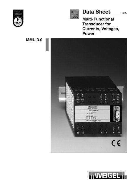
MMU 3.0<br />
<br />
Data Sheet 055.9e<br />
Multi-Functional<br />
Transducer for<br />
Currents, Voltages,<br />
Power
Application<br />
The multi - functional transducer MMU 3.0 accepts any measurable<br />
quantity in existing single- phase or three- phase power supply systems,<br />
converts these input signals into a load independent DC current and/or<br />
impressed DC voltage (current and voltage are synchronous on analog<br />
output 1) and issues the measured values parametrically to an interface<br />
RS 232 and RS 485. A digital output is also available in the basic version.<br />
Transducers with additional analog outputs (voltage or current programmable)<br />
and/or four resp. eight additional digital outputs are optionally<br />
available.<br />
Inputs (exept 10 V measuring input) are galvanically isolated from outputs<br />
and the auxiliary voltage input. The outputs are short - circuit proof<br />
and safe against idling.<br />
The transducers comply with the safety requirements and are tested for<br />
interference immunity.<br />
The transducers are designed to be mounted in machines/systems.<br />
Regulations for installation of electrical systems and equipment have to<br />
be observed.<br />
Measurement<br />
The multi - functional transducer processes input currents up to 5 A and<br />
input voltages up to 519 V at rated frequencies of 50 Hz and 60 Hz.<br />
Depending on the measurement task, input terminals not required remain<br />
idle.<br />
Measurement is effected in true RMS - values including wave forms up<br />
to the 50 th harmonics.<br />
Analog Outputs<br />
Any of the measurable quantities (current, voltage, active-, reactive -<br />
power, frequency etc.) can be allocated to each of the analog outputs.<br />
The analog output available in the basic version synchronously provides<br />
voltage and current (4 terminals). The output signal of each of the optional<br />
analog outputs can be parametrized freely (0/4 ... 20 mA, 0/2 ... 10<br />
V, –10 ... 10 mA; linear or buckled characteristic curve).<br />
Selection between current or voltage output is effected by software.<br />
It is possible to connect more than one indicator, recorder or controller to<br />
the output circuit provided the total impedance does not exceed the rating.<br />
RS 232/485<br />
The transducers are equipped with both a RS 232 and a RS 485 interface<br />
enabling to request measured values and to perform adjustments. When<br />
using the RS 485 interface, up to 32 devices can be networked and read<br />
out via a 2- wire line (1000 m maximum length).<br />
Digital Outputs<br />
The digital outputs can be used as switching contacts for setpoint controlling.<br />
Auxiliary Supply<br />
Power supply is effected by a separate auxiliary voltage input.<br />
Software<br />
The software WSoft ready for execution on Windows 95/98/2000/XP is<br />
available for control of functions and for read - out of measured values.<br />
The control is effected by the widespread machine language SCPI.<br />
Operating Principle<br />
Transformers in the current and voltage circuits galvanically isolate the<br />
power inputs from the electronic circuitry. Hold- /sequence-circuits process<br />
the input signals and transfer them via a multiplexer and a AD- converter<br />
to the microprocessor which processes the signals and computes<br />
all important measuring quantities.<br />
The transducer is connected to the PC via a commercially available<br />
RS232 cable (9 - contact 1:1 connection, socket - plug. An optional connection<br />
will be a 3 - contact cable provided the signals DTR and DSR as<br />
well as RTS and CTS will be two - way bridged.)<br />
Block Circuit Diagram<br />
U L1<br />
U L2<br />
U L3<br />
I L1<br />
I L2<br />
I L3<br />
U H<br />
Sequence -/<br />
Hold -<br />
Circuit<br />
Multiplexer<br />
~ =<br />
<br />
<br />
10 V Measuring Input<br />
P<br />
<br />
<br />
General Technical Data<br />
R A<br />
R A<br />
Analog Output 1<br />
I A<br />
U A<br />
Interfaces<br />
RS 232<br />
RS 485<br />
Digital Output 1<br />
(galvanically<br />
isolated)<br />
additional galvanically<br />
isolated voltage-,<br />
current - resp.<br />
digital outputs<br />
(optional)<br />
case details<br />
projecting case clamping to TH 35 DIN<br />
rail according to DIN EN 60 715<br />
material of case Cycoloy C2950 black<br />
self-extinguishing to UL rating 94 V–0<br />
terminals<br />
screw - terminals, maximum torque 0.8 Nm<br />
wire cross - section 4 mm 2 max.<br />
enclosure code IP 40 case<br />
IP 20 terminals<br />
dielectric test<br />
<strong>221</strong>0 V all circuits to case<br />
3536 V currents to each other and to voltages;<br />
inputs (exept 10 V measuring input) to<br />
outputs, auxiliary voltage and interfaces;<br />
auxiliary voltage to outputs and interfaces;<br />
1000 V= outputs to each other (the analog output 1 is<br />
galvanically connected to 10 V measuring<br />
input and to interfaces.)<br />
operating voltage 300 V (rated voltage phase to zero)<br />
class of protection II<br />
measurement category CAT III<br />
pollution level 2<br />
dimensions<br />
basic version: 3 modules in single - phase<br />
system resp. 4 modules in three - phase<br />
systems,<br />
optional outputs: additional 1 to 3 modules<br />
each module WxHxL 22.5 mm x 80 mm x 115 mm<br />
weight<br />
approx. 0.6 kg (basic version)
Inputs<br />
input quantities AC current and AC voltage<br />
voltages<br />
L1, L2, L3 (3 terminals), N (1 terminal)<br />
currents<br />
I1, I2, I3 (6 terminals)<br />
auxiliary supply U H (2 terminals)<br />
10 V measurement e.g. connecting an analog converter<br />
input<br />
rated input current N/5 A <br />
I EN<br />
rated input voltage 519 V (inter- connected) <br />
U EN<br />
operating voltage 519 V max.<br />
modulation range 1.2 U EN and 1.2 I EN<br />
overload limits 1.2 U EN , 1.6 I EN continuously<br />
2 U EN , 10 I EN max. 1 s<br />
frequency range 50 ... 60 Hz<br />
power consumption 2 mA 10% each voltage circuit<br />
≤ 0.1 VA each current circuit for I EN = 1 A<br />
≤ 1.6 VA each current circuit for I EN = 5 A<br />
Measuring Quantities<br />
Measuring Quantity Total L1 L2 L3<br />
voltage (U) U U 1 U 2 U 3<br />
current (I) I 1 ) I 1 I 2 1 ) I 3<br />
active power (P) P P 1 P 2 1 ) P 3<br />
reactive power (Q) Q Q 1 Q 2 1 ) Q 3<br />
<br />
Data Sheet 055.9e<br />
Multi-Functional<br />
Transducer for<br />
Currents, Voltages,<br />
Power<br />
current output<br />
output current I A load independent DC current<br />
rated current I AN 0 (4) ... 20 mA or<br />
0 ... 10 mA (parameterizable)<br />
load range R A 0 ... 500 (based on 20 mA)<br />
0 ... 1000 (based on 10 mA)<br />
load error<br />
≤ 0.1% based on 50% load change<br />
residual ripple ≤ 1% rms of I AN with load R A<br />
idling voltage ≤ 16 V<br />
current limitation up to 24 mA<br />
voltage output<br />
output voltage U A load independent DC voltage<br />
rated voltage U AN 0 (2) ... 10 V (parameterizable)<br />
load R A ≥ 4 k (based on U AN )<br />
load error<br />
≤ 0.1% based on 50% load change<br />
residual ripple ≤ 1% rms of U AN with load R A = U AN / 2 mA<br />
idling voltage ≤ 16 V<br />
voltage limitation up to 12 V<br />
Inputs (exept 10 V measuring input) and outputs are galvanically isolated.<br />
Conversion Characteristics<br />
examples<br />
standard “live zero” incoming and outgoing<br />
I A ,<br />
U A<br />
I A ,<br />
U A<br />
I A ,<br />
U A<br />
apparent power (S) S S 1 S 2 1 ) S 3<br />
active factor (PF) PF PF 1 PF 2 1 ) PF 3<br />
measuring<br />
quantity<br />
reactive factor (QF) QF QF 1 QF 2 1 ) QF 3<br />
phase angle (PH) PH PH 1 PH 1 2 ) PH 3<br />
frequency (f)<br />
F<br />
Depending on power system, it will not be possible to measure all these<br />
values.<br />
I A ,<br />
U A<br />
measuring<br />
quantity<br />
I A ,<br />
U A<br />
measuring<br />
quantity<br />
I A ,<br />
U A<br />
10 V measuring input <br />
Outputs<br />
Outputs <br />
analog output 1<br />
voltage & current synchronous<br />
(2 terminals each)<br />
interfaces<br />
RS 232 (SUB–D jack)<br />
RS 485 (2 terminals)<br />
(All outputs listed above and the analog input have one and the same<br />
potential.)<br />
digital output<br />
contact-free via opto coupler,<br />
max. 230 V / 100 mA,<br />
internal resistance 25 ... 35 ,<br />
insulation voltage 2.3 kV,<br />
switching frequency admissible ≤2 Hz<br />
1, 2, or 3 additional analog outputs (galvanically isolated) and<br />
up to 8 additional digital outputs (galvanically isolated) are optional <br />
response time ≤ 500 ms,<br />
based on 50 Hz exception for 3 - phase 3 - wire unbalanced<br />
load system for quantities marked with 1 )<br />
(see table Measuring Quantities): ≤ 750 ms<br />
additional response<br />
time for serial output<br />
refer also to Extras<br />
20 ms for each value<br />
(RS 232/485, 19,200 baud)<br />
measuring<br />
quantity<br />
buckled characteristic curve<br />
I A ,<br />
U A<br />
measuring<br />
quantity<br />
Interfaces<br />
I A ,<br />
U A<br />
measuring<br />
quantity<br />
measuring<br />
quantity<br />
type<br />
RS 232 (V.24) and<br />
RS 485 (SCPI commands)<br />
Baud rate<br />
19200 Baud<br />
data bit 8<br />
parity<br />
none<br />
stop bit 2<br />
I A ,<br />
U A<br />
measuring<br />
quantity<br />
measuring<br />
quantity
Auxiliary Supply<br />
auxiliary voltage U HN<br />
power consumption<br />
wide-range supply<br />
20 ... 90 V DC resp. 15 ... 65 V AC,<br />
90 ... 357 V DC resp. 65 ... 253 V AC<br />
< 10 VA<br />
Accuracy at Reference Conditions<br />
accuracy<br />
better than class 0.5 (0.5% of end value)<br />
exception for 3 - phase 3 - wire<br />
unbalanced load system for quantities<br />
marked with 1 )<br />
(see table Measuring Quantities)<br />
These ratings are calculated values<br />
(Aron circuit):<br />
class 1.5 (1.5% of end value)<br />
temperature coefficient ≤ 0.06%/K<br />
valid for standard products and a life - period of 1 year maximum<br />
reference conditions<br />
input current<br />
I EN 0.5%<br />
input voltage U EN 0.5%<br />
power factor cos ϕ =1<br />
frequency<br />
50 Hz<br />
wave form sine wave, distortion factor ≤ 1%<br />
auxiliary voltage U HN 1%, 48 ... 62 Hz<br />
load<br />
0.5 R A max 1% based on current<br />
10 k 1% based on voltage<br />
ambient temperature 23C 1K<br />
warm-up<br />
≥5 min<br />
Environmental<br />
climatic suitability climatic class 3 to VDE/VDI 3540 sheet 2<br />
operating<br />
–10 ... +55C<br />
temperature range<br />
storage<br />
–25 ... +65C<br />
temperature range<br />
relative humidity ≤ 75% annual average, non - condensing<br />
Rules and Standards<br />
DIN EN 60 529 Enclosure codes by housings (IP - code)<br />
DIN EN 60 688 Electrical measuring transducers<br />
converting AC quantities into analog or<br />
digital signals<br />
DIN EN 60 715 Dimensions of low voltage switching devices:<br />
standardized DIN rails for mechanical fixation<br />
of electrical devices in switchgears<br />
DIN EN 61 010 - 1 Safety requirements for electrical measuring,<br />
control and laboratory equipment<br />
Part 1: General requirements<br />
DIN EN 61 326 - 1 Electrical equipment for measurement, con -<br />
trol and laboratory use – EMC requirements<br />
Part 1: General requirements<br />
(IEC 61 000 - 4-3 evaluation criterion B)<br />
VDE/VDI 3540 sheet 2 Reliability of measuring and control<br />
equipment (classification of climates for<br />
equipment and accessories)
Connections<br />
<br />
Terminals<br />
Data Sheet 055.9e<br />
Multi-Functional<br />
Transducer for<br />
Currents, Voltages,<br />
Power<br />
input<br />
D61 D62<br />
D71 D72<br />
D21 D22<br />
D31 D32<br />
– A2 +<br />
– A3 +<br />
1 3<br />
D11 D12<br />
4 6<br />
7 9<br />
14 13<br />
20 19<br />
active and reactive power, single - phase<br />
front view<br />
active and reactive power, 3 - phase, 3 - wire, balanced load<br />
active and reactive power, 3 - phase, 4 - wire, balanced load<br />
D81 D82<br />
D91 D92<br />
digital<br />
outputs<br />
6 to 9<br />
terminal MMU 3.0<br />
1 I E L 1<br />
2 U E L 1<br />
3 I E L 1<br />
4 I E L 2<br />
5 U E L 2<br />
6 I E L 2<br />
7 I E L 3<br />
8 U E L 3<br />
D41 D42<br />
D51 D52<br />
digital<br />
outputs<br />
2 to 5<br />
– A4 +<br />
analog<br />
outputs<br />
2 to 4<br />
2 11<br />
17 16<br />
5 8 E– E+<br />
basic version for 3 (one<br />
module inapplicable for single<br />
)<br />
A<br />
B<br />
active and reactive power, 3 - phase, 3 - wire, unbalanced load<br />
active and reactive power, 3 - phase, 4 - wire, unbalanced load<br />
9 I E L 3<br />
11 U E N<br />
13 U A1 (+)<br />
14 U A1 (–)<br />
16 U H L 1 (+)<br />
17 U H N (–)<br />
19 I A1 (+)<br />
20 I A1 (–)<br />
E+ U E (+)<br />
E– U E (–)<br />
A RS 485<br />
B RS 485<br />
RS 232<br />
Dn1 digital output n, contact 1, (n = 1 ... 9)<br />
Dn2 digital output n, contact 2, (n = 1 ... 9)<br />
Am– analog output m, negative pole, (m = 2 ... 4)<br />
Am+ analog output m, positive pole, (m = 2 ... 4)<br />
Depending on the measurement task, input - resp. output - terminals remain<br />
idle.<br />
I E current input<br />
U E voltage input<br />
The numbers on the terminals correspond to details<br />
in connection diagrams (refer to DIN 43 807).<br />
I A current output<br />
U A voltage output<br />
U H auxiliary voltage input
RS232-Interconnection<br />
DSR 6<br />
RTS 7<br />
CTS 8<br />
RI 9<br />
Extras<br />
1 DCD<br />
2 RxD<br />
3 TxD<br />
4 DTR<br />
5 GND<br />
9<br />
<br />
3<br />
<br />
outputs<br />
1, 2 or 3 additional can be parametrized via software between<br />
analog outputs 20 mA (load4 k);<br />
galvanically isolated,<br />
power supply unit integrated<br />
(width: 1 module)<br />
4 or 8 additional 230 V, galvanically isolated<br />
digital outputs (width: 1 resp. 2 modules)<br />
rated input current N/1.2 A (also programmable for N/1 A,<br />
I EN<br />
with same accuracy)<br />
rated input voltage N/120 V (inter- connected)<br />
U EN (also programmable for N/100 V or N/110 V,<br />
with same accuracy)<br />
Dimensions<br />
example: basic version with 3 modules, width: each module 22.5 mm<br />
side view<br />
115<br />
80<br />
67.5<br />
front view<br />
Ordering Guide<br />
type<br />
E<br />
D<br />
A1<br />
A2<br />
A3<br />
multi- functional transducer<br />
for currents, voltages, power<br />
MMU 3.0<br />
basic version for single - phase AC<br />
basic version for 3 - phase network<br />
outputs * )<br />
analog output 1 (voltage & current synchronous)<br />
digital output 1<br />
analog outputs<br />
1 additional analog output with basic version<br />
2 additional analog outputs with basic version<br />
3 additional analog outputs with basic version<br />
Ax additional analog outputs with basic version ** )<br />
D4<br />
D8<br />
H4<br />
H5<br />
digital outputs<br />
4 additional digital outputs with basic version<br />
8 additional digital outputs with basic version<br />
auxiliary supply<br />
DC 20 ... 90 V / AC 15 ... 65 V<br />
DC 90 ... 357 V / AC 65 ... 253 V<br />
programming<br />
P0 by user * )<br />
P1<br />
by factory<br />
accessory<br />
WSoft software on CD for configuration and<br />
read-out of measured values<br />
RS 232 – RS 232 cable (serial connection cable)<br />
USB – RS 232 converter with cable (1.8 m)<br />
AP-RS232/485 RS 232-485 converter<br />
* ) standard<br />
** ) on request<br />
Note: Data relating to input, measuring range and to the output assignment<br />
are not required, as the transducers are suitable to be configured<br />
with a PC or laptop.<br />
ordering example<br />
MMU 3.0 D D4 H5 P0 WSoft<br />
multi- functional transducer for use on 3- phase network<br />
(1 analog output and 1 digital output included),<br />
not any additional analog outputs,<br />
4 additional digital outputs,<br />
auxiliary voltage DC 90...357V/AC 65...253V,<br />
user-programming; software WSoft<br />
(dimensions in mm)<br />
<strong>Weigel</strong> Meßgeräte <strong>GmbH</strong><br />
Postfach 720 154 90241 Nürnberg Phone: 0911/42347-0<br />
Erlenstraße 14 90441 Nürnberg Fax: 0911/42347-39<br />
Sales: Phone: 0911/42347-94<br />
Internet:<br />
http://www.weigel–messgeraete.de<br />
e–mail:<br />
vertrieb@weigel–messgeraete.de