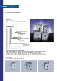
1. General 2. Type Designation 3. Features NA1 Air Circuit Breaker ...
1. General 2. Type Designation 3. Features NA1 Air Circuit Breaker ...
1. General 2. Type Designation 3. Features NA1 Air Circuit Breaker ...

You also want an ePaper? Increase the reach of your titles
YUMPU automatically turns print PDFs into web optimized ePapers that Google loves.
<strong>1.</strong> <strong>General</strong><br />
.<strong>1.</strong><br />
INGTERTEK<br />
<strong>2.</strong> <strong>Type</strong> <strong>Designation</strong><br />
N A 1 - � / �<br />
<strong>3.</strong> <strong>Features</strong><br />
<strong>Circuit</strong> <strong>Breaker</strong>s<br />
<strong>NA1</strong> <strong>Air</strong> <strong>Circuit</strong> <strong>Breaker</strong><br />
<strong>1.</strong>1 Certificates: CB, SEMKO, PCT, RCC,KEMA;<br />
<strong>1.</strong>2 Electric ratings: 400~6300A, 400/690V, AC50/60Hz;<br />
<strong>1.</strong>3 Number of poles: 3, 4;<br />
<strong>1.</strong>4 Mounting versions: Horizontal and vertical<br />
<strong>1.</strong>5 Application: used for protection of power distribution system;<br />
<strong>1.</strong>6 Standard: IEC 60947-2<br />
Number of poles; Blank: 3P; 4: 4P<br />
Frame level rated current<br />
Design sequence number<br />
<strong>Air</strong> circuit breaker<br />
Company code<br />
<strong>3.</strong>1 Compact design with fixed and withdrawable version;<br />
<strong>3.</strong>2 Easy maintenance thanks to modular design and<br />
independence of each functional part;<br />
4. Operating Conditions<br />
4.1 Ambient temperature:<br />
a. -5 �~+40 �, the average temperature within 24 hours not exceed +35 �;<br />
b. Customized breakers are available for the breaker of which the upper limit of temperature is +40�orthe lower limit is �-25 �;<br />
c. Refer to table below for temperature compensation correction.<br />
Ambient<br />
temperature<br />
40�<br />
45�<br />
50�<br />
55�<br />
60�<br />
65�<br />
630<br />
630<br />
630<br />
630<br />
610<br />
610<br />
800<br />
800<br />
800<br />
800<br />
800<br />
800<br />
Rated current of<br />
<strong>NA1</strong>-2000 (A)<br />
1000<br />
1000<br />
1000<br />
1000<br />
1000<br />
1000<br />
1250<br />
1250<br />
1250<br />
1200<br />
1150<br />
1150<br />
1600<br />
1600<br />
1500<br />
1500<br />
1300<br />
1300<br />
2000<br />
1900<br />
1900<br />
1800<br />
1700<br />
1650<br />
Rated current of<br />
<strong>NA1</strong>-3200, 4000 (A)<br />
2000<br />
2000<br />
2000<br />
2000<br />
2000<br />
2000<br />
2500<br />
2400<br />
2300<br />
2200<br />
2200<br />
2200<br />
3200<br />
3000<br />
3000<br />
2800<br />
2800<br />
2600<br />
4000<br />
3800<br />
3600<br />
3400<br />
3200<br />
3200<br />
Rated current of<br />
<strong>NA1</strong>-6300 (A)<br />
4.2 Altitude: �2000m;<br />
4.3 Relative humidity: At mounting site, relative humidity not exceed 50% at the max temperature of +40 �,<br />
higher relative<br />
humidity is allowable under lower temperature. For example, RH could be 90% at +20 �.Special<br />
measures should be taken to<br />
occurrence of dews.<br />
4.4 Pollution grade: �;<br />
4.5 Power loss per pole<br />
Inm (A)<br />
In (A)<br />
Power<br />
loss<br />
Withdrawerable<br />
type<br />
Fixed type<br />
630<br />
70<br />
34.4<br />
800<br />
110<br />
50<br />
4000<br />
4000<br />
4000<br />
4000<br />
4000<br />
4000<br />
5000<br />
5000<br />
5000<br />
4800<br />
4800<br />
4800<br />
<strong>NA1</strong>-2000 <strong>NA1</strong>-3200 <strong>NA1</strong>-4000 <strong>NA1</strong>-6300<br />
1000<br />
172<br />
78<br />
1250<br />
268<br />
122<br />
1600<br />
440<br />
200<br />
2000<br />
530<br />
262<br />
2000<br />
384<br />
200<br />
2500<br />
600<br />
312<br />
3200<br />
737<br />
307<br />
4000/3P<br />
921<br />
-<br />
4000/4P<br />
900<br />
-<br />
4000<br />
575<br />
-<br />
5000<br />
898<br />
-<br />
6300<br />
6000<br />
5600<br />
5400<br />
5200<br />
5100<br />
6300<br />
1426<br />
-
4.6 Temperature compensation curves<br />
Rated current �A� 2000<br />
1900<br />
1800<br />
1700<br />
1600<br />
1500<br />
1400<br />
1300<br />
1200<br />
1100<br />
1000<br />
900<br />
800<br />
700<br />
600<br />
500<br />
400<br />
5. Technical Data<br />
Model<br />
In=2000A<br />
In=1600A<br />
In=1250A<br />
In=1000A<br />
In=800A<br />
In=630A<br />
Frame level rated current Inm (A)<br />
Number of poles<br />
Rated current In (A)<br />
40 45 50 55 60 65 70<br />
Environmental temperature���<br />
400V<br />
Icu (kA)<br />
690V<br />
400V<br />
Ics=Icw (kA)<br />
690V<br />
Rated current at N-pole In (A)<br />
Inherent making & breaking time<br />
Electric life<br />
Operating performances<br />
(operations)<br />
Mechanical life<br />
Mounting mode<br />
Arcing distance (mm)<br />
Intelligent<br />
Standard type (M)<br />
controller Telecommunication type (H)<br />
Rated current �A� 7000<br />
6800<br />
6600<br />
6400<br />
6200<br />
6000<br />
5800<br />
5600<br />
5400<br />
5200<br />
5000<br />
4800<br />
4600<br />
4400<br />
4200<br />
4000<br />
3800<br />
<strong>NA1</strong>-2000 <strong>NA1</strong>-3200�4000 In=6300A<br />
In=5000A<br />
In=4000A<br />
40 45 50 55 60 65 70<br />
<strong>NA1</strong>-2000<br />
Environmental temperature���<br />
Rated current �A� 5000<br />
4800<br />
4600<br />
4400<br />
4200<br />
4000<br />
3800<br />
3600<br />
3400<br />
3200<br />
3000<br />
2800<br />
2600<br />
2400<br />
2200<br />
2000<br />
1800<br />
In=4000A<br />
In=3200A<br />
In=2500A<br />
In=2000A<br />
40 45 50 55 60 65 70<br />
Environmental temperature���<br />
<strong>NA1</strong>-6300<br />
<strong>NA1</strong>-3200 <strong>NA1</strong>-4000 <strong>NA1</strong>-6300<br />
2000<br />
3200<br />
4000 4000�5000�6300 3�4 3�4 3�4 (400), 630, 800, 1000,<br />
1250, 1600, 2000<br />
2000, 2500, 3200<br />
4000<br />
4000, 5000, 6300<br />
80<br />
80(100)<br />
80(100)<br />
120<br />
50<br />
80<br />
80<br />
80<br />
50<br />
80<br />
80<br />
100<br />
40<br />
65<br />
65<br />
65<br />
50% In, 100% In<br />
50% In, 100% In<br />
50% In, 100% In 50% In, 100% In<br />
23-32 ms<br />
23-32 ms<br />
23-32 ms<br />
23-32 ms<br />
500<br />
500<br />
500<br />
500<br />
Maintenance-free 2500 Maintenance-free 2500 Maintenance-free 2500 Maintenance-free 2500<br />
Maintainable 10000 Maintainable 10000 Maintainable 10000 Maintainable 10000<br />
Fixed�Withdrawable Fixed�Withdrawable Fixed�Withdrawable Withdrawable<br />
0<br />
0 0 0<br />
�<br />
� � �<br />
�<br />
� � �<br />
.<strong>2.</strong>
7. Structure<br />
.5.<br />
<strong>Circuit</strong> <strong>Breaker</strong>s<br />
7.1 Fixed version<br />
Fault-breaking indicator<br />
reset button<br />
Off button<br />
On/off indicator<br />
Handle<br />
Rotate out<br />
7.2 Withdrawable version<br />
Drawer base<br />
8. Intelligent Controller<br />
Enclosure<br />
Rotate in<br />
On button<br />
Energy storage &<br />
release indicator<br />
Name plate<br />
Structure for in and out<br />
Body<br />
Locking device<br />
+ =<br />
Intelligent controller is one of the core components of the circuit breaker;<br />
8.1 Properties of the intelligent controller<br />
a. protective functions of over-load long time-delay and inverse time<br />
limit, short time-delay and inverse time limit, short time-delay<br />
definite time limit instantaneous operation protection;<br />
b. Single-phase grounding failure protection;<br />
c. Display of setting current Ir and operational current;<br />
d. Ampere meter;<br />
e. Over-load alarm;<br />
f. Short-circuit alarm;<br />
g.<br />
Testing of operation properties<br />
Note: The breakers with telecommunication port are available to realize<br />
remote control to breaker through master computer.<br />
Intelligent controller<br />
Under-voltage release<br />
Shunt release<br />
Closing electromagnet<br />
Auxiliary contact<br />
Electric motor
8.2 Protection performances of over-current release<br />
a. Ir and its error of the controller<br />
Frame level rated<br />
current Inm (A)<br />
Long time-delay Short time-delay Instantaneous Grounding failure<br />
Ir1 Error Ir2 Error Ir3 Error Ir4<br />
Inm�4000A (0.2~0.8)<br />
Error<br />
In (Max.1200A, Min.200A)<br />
Inm=6300A (0.2~<strong>1.</strong>0) In<br />
�10%<br />
�2000 (0.4~1) In �10% (0.4~15) In �10% <strong>1.</strong>0 In ~ 50kA �15%<br />
Note:<br />
<strong>1.</strong> When the breaker could realize over-load with long time delay,short-circuit with short time-delay and short-circuit instantaneous<br />
protections, the setting ratings can not be over-lapped, and Ir1�Ir2�Ir3; <strong>2.</strong> When the frame level is 3200A and above, the setting ratings range from <strong>1.</strong>01In to 75kA.<br />
b. Characteristics of long time-delay protection.<br />
<strong>1.</strong>05 Ir1 <strong>1.</strong>3 Ir1 <strong>1.</strong>5 Ir1 <strong>2.</strong>0 Ir1<br />
�2h non-tripping �1h tripping 15s, 30s, 60s, 120s, 240s, 480s 8.4s, 16.9s, 3<strong>3.</strong>7s, 67.5s, 135s, 270s<br />
c. Characteristics of short time-delay protection.<br />
For low over-current, inverse time-limit protection could be realized; when the over-current is �8Ir1,<br />
it will automatically change<br />
to be definite time-limit protection properties.<br />
Refer to table below for time-limit properties.<br />
Setting delay time ts (s) Returnable time (s)<br />
0.1, 0.2, 0.3, 0.4 0.06, 0.14, 0.23, 0.35<br />
Note: Definite time-limit delay time(s): 0.11, 0.21, 0.31, 0.4<strong>1.</strong><br />
d. Over-current protection curve for breaker of which<br />
Inm�2000A Ir2=(1~15)Ir1<br />
e. Time-delay property curve for grounding failure protection<br />
for breaker of which Inm�2000A .6.
.7.<br />
<strong>Circuit</strong> <strong>Breaker</strong>s<br />
9. Standard Composition<br />
To facilitate your ordering and utilization, the <strong>NA1</strong> air circuit breaker is appended with basic electric accessories as follows.<br />
Standard composition of the breaker Fixed version Withdrawable version<br />
Body<br />
Drawer base<br />
Intelligent controller<br />
Electric motor<br />
Closing electro-magnet<br />
Shunt release<br />
Under-voltage release<br />
Auxiliary contact<br />
Door frame<br />
10. Accessories<br />
10.1 Shunt release<br />
a. Shunt release is for remote breaking of circuit breaker so as to enhance security of the operator;<br />
b. Ratings of shunt release<br />
Rated operational voltage (V)<br />
Operational voltage range<br />
Power consumption<br />
Rated operational voltage (V)<br />
Operational voltage range<br />
Power consumption<br />
�<br />
�<br />
�<br />
�<br />
�<br />
�<br />
�<br />
�<br />
AC220V AC380V DC110V DC220V<br />
24VA<br />
(70%~110%) Ue<br />
24VA<br />
40W<br />
10.2 Under-voltage release<br />
a. It is an optional accessory;<br />
b. Mainly used to protect apparatus from damage due to lowering of the operational voltage to a<br />
certain value;<br />
c. Two types of release are available: instantaneous release and time-delay release.<br />
d. For breakers appended with the release, it should be electrified continuously;<br />
e. Ratings of under-voltage release.<br />
f. Operation properties of under-voltage release<br />
Category<br />
Operation time of the release<br />
35~70% Us<br />
Operational voltage of<br />
�35%<br />
Us<br />
the release<br />
�85%<br />
Us~110% Us<br />
Within 1/2 delay time,<br />
voltage of power supply recovers to 85% Us<br />
Note: Error of the time of time-delay is�10%. AC220V AC380V DC110V DC220V<br />
(35%~110%)Us<br />
24VA 24VA<br />
40W<br />
Under-voltage<br />
time-delay release<br />
Time-delay: 1s, 3s, 5s<br />
Break the breaker<br />
Can not make the breaker<br />
Reliably make the breaker<br />
Can not break the breaker<br />
�<br />
�<br />
�<br />
�<br />
�<br />
�<br />
�<br />
�<br />
�<br />
Under-voltage<br />
instantaneous release<br />
Instantaneous<br />
Break the breaker<br />
Can not make the breaker<br />
Reliably make the breaker
10.3 Closing electro-magnet<br />
a. The magnet is for remote making of circuit breaker so as to enhance security of the operator;<br />
b. The magnet could not be electrified for a long time.<br />
c. Ratings of the magnet<br />
Rated operational voltage (V)<br />
Operational voltage range<br />
Power consumption<br />
AC220V AC380V DC110V DC220V<br />
(85%~110%)Us<br />
40VA 40VA<br />
40W<br />
10.4 Auxiliary contact<br />
a. Conventional heating current of auxiliary contact: 6A;<br />
b. Auxiliary contacts: 4NO+ 4NC, 3NO+3NC, 5NO+5NC (customization)<br />
10.5 Locking device at the breaking status<br />
a. Once the device is pushed , the breaker can not be made anymore;<br />
b. Locks and keys will be provided by us on ordering;<br />
c. For various ordering quantity, we will provide locking devices and keys of certain quantity:<br />
d. For the withdrawable version of breaker, padlocks should be used for locking, and the testing<br />
and<br />
breaking positions are not available for the breaker;<br />
e. Padlocks should be prepared by the users.<br />
10.6 Mechanical interlock<br />
Mounting hole<br />
Three circuit breakers interlocked through the pole. The interlocking of two<br />
circuit breakers is available when the opper breaker is dismounted.<br />
.8.
.1<strong>1.</strong><br />
<strong>Circuit</strong> <strong>Breaker</strong>s<br />
1<strong>1.</strong>4 Horizontal rear connection (by the user)<br />
�������<br />
�������<br />
��<br />
�� �� ���<br />
���<br />
���<br />
�����<br />
��� ��<br />
�������<br />
1<strong>1.</strong>5 Vertical rear connection (by the manufacturer)<br />
�������<br />
�������<br />
��<br />
�� �� ���<br />
���<br />
���<br />
���<br />
��� ��<br />
�<br />
��<br />
��<br />
�������<br />
�<br />
�<br />
�����<br />
��� ��<br />
��<br />
���� �����<br />
�� �� ��� ����<br />
�����<br />
���<br />
���<br />
��� ����<br />
�� ��<br />
�����<br />
���<br />
���<br />
���<br />
Holes on the plate<br />
���<br />
���<br />
���<br />
���<br />
���<br />
�������<br />
�������<br />
���<br />
�������<br />
�������<br />
��<br />
15.5 Righte outer sid of the breaker<br />
����<br />
Mounting plate of circuit breaker<br />
���<br />
��<br />
���<br />
�����<br />
���<br />
���� ����<br />
����<br />
����<br />
��<br />
��<br />
��<br />
Mounting diagram of rotatory busbar for <strong>NA1</strong>-3200 withdrawerable version<br />
���<br />
Holes on the plate<br />
���<br />
���<br />
���<br />
�������<br />
�������<br />
�����<br />
���<br />
�������<br />
�������<br />
��<br />
15.5 Righte outer sid of the breaker<br />
Mounting plate of circuit breaker<br />
����<br />
���<br />
��<br />
�<br />
�<br />
��<br />
�� �����<br />
���<br />
�<br />
�� �� ��<br />
��<br />
�����<br />
����� ����<br />
����<br />
���<br />
�<br />
��<br />
��<br />
����<br />
��<br />
��<br />
��� ���<br />
��
1<strong>1.</strong>6 Horizontal rear connection (by the user)<br />
1<strong>1.</strong>7 <strong>NA1</strong>-3200 Withdrawable version circuit breaker<br />
440(4P)<br />
�������<br />
55<br />
��<br />
10<br />
325(3P)<br />
�������<br />
��<br />
97 175<br />
491<br />
536<br />
�� �� ���<br />
�11<br />
�14<br />
���<br />
���<br />
175<br />
33<br />
Right & outer side<br />
of breaker<br />
��� ��<br />
���<br />
a<br />
112<br />
23<br />
2-11�17 �������<br />
a<br />
92<br />
�<br />
268 2<strong>1.</strong>5<br />
11-�5 ��� ����<br />
�� ��<br />
�����<br />
20<br />
47<br />
��� �<br />
�����<br />
528(4P)<br />
413(3P)<br />
352<br />
435(3P)<br />
550(4P)<br />
362<br />
���<br />
���<br />
202<br />
404<br />
Holes on the plate<br />
���<br />
Holes on the plate<br />
155<br />
���<br />
302<br />
���<br />
37<br />
4<strong>2.</strong>5<br />
378<br />
15.5<br />
���<br />
258<br />
439<br />
70<br />
Right & outer side<br />
of breaker<br />
Mounting plate of<br />
circuit breaker<br />
�������<br />
�������<br />
�����<br />
352<br />
�������<br />
�������<br />
15.5 Righte outer sid of the breaker<br />
Mounting plate of circuit breaker<br />
115<br />
32-�13 In A<br />
2000~2500<br />
3200<br />
107<br />
17<br />
��<br />
16-�13 100<br />
N 50<br />
15<br />
N<br />
����<br />
���<br />
���<br />
��<br />
20<br />
amm<br />
20<br />
30<br />
115 125 125<br />
Horizontal connection<br />
40<br />
100<br />
95<br />
115 125 125<br />
�<br />
Vertical wiring<br />
�����<br />
����<br />
�<br />
����<br />
����<br />
����<br />
��<br />
��<br />
100<br />
N 50<br />
40<br />
125 125<br />
50<br />
40<br />
94<br />
.1<strong>2.</strong>
.1<strong>3.</strong><br />
<strong>Circuit</strong> <strong>Breaker</strong>s<br />
1<strong>1.</strong>8 <strong>NA1</strong>-3200 Fixed version circuit breaker<br />
50<br />
150 69.5<br />
290<br />
389<br />
4-�12 400(3P)<br />
515(4P)<br />
150<br />
a<br />
112<br />
a<br />
55<br />
60<br />
335<br />
402<br />
28.5<br />
<strong>Circuit</strong> breaker mounting<br />
holes on left side<br />
269<br />
493(4P)<br />
378(3P)<br />
352<br />
11 11<br />
400(3P)<br />
515(4P)<br />
8-�5 362<br />
<strong>Circuit</strong> breaker mounting<br />
holes on left side<br />
404<br />
Holes on the plate<br />
1<strong>1.</strong>9 <strong>NA1</strong>-4000 Withdrawable version circuit breaker (3-poles)<br />
440<br />
�11<br />
�14<br />
175<br />
45<br />
33<br />
10<br />
97 175<br />
2-11�17 494<br />
268 2<strong>1.</strong>5<br />
11-�5 20<br />
47<br />
30<br />
112<br />
92<br />
362<br />
202<br />
404<br />
Holes on the plate<br />
155<br />
302<br />
378<br />
21<br />
311<br />
258<br />
13<br />
115<br />
2<br />
Mounting plate of<br />
circuit breaker<br />
528<br />
352<br />
550<br />
32-�13 37<br />
In A<br />
2000~2500<br />
3200<br />
72<br />
15<br />
110<br />
12-�13 4<strong>2.</strong>5<br />
Right &outer<br />
side of breaker<br />
15.5<br />
Mounting plate of circuit breaker<br />
16-�13 86<br />
N 40<br />
15<br />
N<br />
70 258<br />
439<br />
115 115 115 40<br />
115<br />
amm<br />
20<br />
30<br />
Horizontal connection<br />
40<br />
86<br />
115 115<br />
Vertical connection<br />
197.5<br />
50<br />
140<br />
20<br />
197.5<br />
40<br />
40
1<strong>1.</strong>10 <strong>NA1</strong>-4000/4 Withdrawable version circuit breaker<br />
45<br />
10<br />
97 175<br />
490<br />
678<br />
55<br />
20<br />
112<br />
92<br />
�14<br />
16-�13 155<br />
N-pole 20<br />
�11<br />
175<br />
80<br />
14<strong>2.</strong>5<br />
33<br />
2-11�17 Right &outer side of breaker<br />
50<br />
206.5<br />
40<br />
Horizontal Wiring<br />
206.5<br />
268 2<strong>1.</strong>5<br />
11-�5 1<strong>1.</strong>11 <strong>NA1</strong>-6300 Withdrawable version circuit breaker (In=4000A, 5000A)<br />
818(4P)<br />
55<br />
703(3P)<br />
�14<br />
175<br />
45<br />
10<br />
97 175<br />
494<br />
2-11�17 268 2<strong>1.</strong>5<br />
11-�5 20<br />
47<br />
30<br />
112<br />
92<br />
362<br />
202<br />
404<br />
155<br />
20<br />
47<br />
302<br />
378<br />
15.5<br />
140<br />
Right & outer<br />
side of breaker<br />
302<br />
172<br />
344<br />
928(4P)<br />
813(3P)<br />
352<br />
835(3P)<br />
950(4P)<br />
�11 110<br />
33<br />
Right & outer side of breaker<br />
Holes on the plate<br />
Holes on the plate<br />
Right & outer<br />
side of breaker<br />
40<br />
155<br />
N<br />
135<br />
Mounting plate of circuit breaker<br />
302<br />
378<br />
756<br />
292<br />
788<br />
Right&outer<br />
15.5<br />
side of breaker<br />
Mounting plate of circuit breaker<br />
37<br />
4<strong>2.</strong>5<br />
70 258<br />
449<br />
182<br />
155 210<br />
55<br />
247<br />
247<br />
37<br />
4<strong>2.</strong>5<br />
70 258<br />
439<br />
28-�15 20<br />
.14.
<strong>Circuit</strong> <strong>Breaker</strong>s<br />
1<strong>3.</strong> Complementary Technical Information<br />
Selection table of transformers, circuit breakers, bus bar and cable<br />
Capacity of transformer (kVA)<br />
and number of transformer in<br />
parallel connection<br />
250�1 250�2 250�3 315�1 315�2 315�3 400�1 400�2 400�3 500�1 500�2 500�3 400�1 400�2 400�3 500�1 500�2 500�3 630�1 630�2 630�3 800�1 800�2 800�3 1000�1 1000�2 1000�3 1250�1 1250�2 1250�3 1600�1 1600�2 1600�3 2000�1 2000�2 2000�3 2500�1 2500�2 3150�1 3150�2 3150�1 3150�2 Rated current<br />
of transformer<br />
In (A)<br />
360<br />
360<br />
360<br />
455<br />
455<br />
455<br />
578<br />
578<br />
578<br />
722<br />
722<br />
722<br />
578<br />
578<br />
578<br />
722<br />
722<br />
722<br />
910<br />
910<br />
910<br />
1154<br />
1154<br />
1154<br />
1444<br />
1444<br />
1444<br />
1805<br />
1805<br />
1805<br />
2310<br />
2310<br />
2310<br />
2887<br />
2887<br />
2887<br />
3608<br />
3608<br />
4550<br />
4550<br />
4550<br />
4550<br />
Short-circuit current<br />
at the general juncture<br />
for down-lead (kA)<br />
9<br />
9<br />
9<br />
1<strong>1.</strong>4<br />
1<strong>1.</strong>4<br />
1<strong>1.</strong>4<br />
14.4<br />
14.4<br />
14.4<br />
18<br />
18<br />
18<br />
14.4<br />
14.4<br />
14.4<br />
18<br />
18<br />
18<br />
2<strong>2.</strong>7<br />
2<strong>2.</strong>7<br />
2<strong>2.</strong>7<br />
19.3<br />
19.3<br />
19.3<br />
24<br />
24<br />
24<br />
30<br />
30<br />
30<br />
36.5<br />
36.5<br />
36.5<br />
48.2<br />
48.2<br />
48.2<br />
60<br />
60<br />
75.8<br />
75.8<br />
75.8<br />
75.8<br />
Breaking capacity of<br />
breaker at the general<br />
juncture for down-lead (kA)<br />
9<br />
9<br />
18.5<br />
1<strong>1.</strong>4<br />
1<strong>1.</strong>4<br />
2<strong>2.</strong>7<br />
14.4<br />
14.4<br />
28.8<br />
18<br />
18<br />
36.1<br />
14.4<br />
14.4<br />
28.8<br />
18<br />
18<br />
36.1<br />
2<strong>2.</strong>7<br />
2<strong>2.</strong>7<br />
44.5<br />
19.3<br />
19.3<br />
38.5<br />
24<br />
24<br />
48.1<br />
30<br />
30<br />
60.1<br />
36.5<br />
36.5<br />
73<br />
48.2<br />
48.2<br />
96.3<br />
60<br />
60<br />
75.8<br />
75.8<br />
75.8<br />
75.8<br />
<strong>Circuit</strong> breaker at the<br />
general juncture for<br />
down-lead (kA)<br />
<strong>NA1</strong>-1000-400<br />
<strong>NA1</strong>-1000-400<br />
<strong>NA1</strong>-1000-400<br />
<strong>NA1</strong>-1000-630<br />
<strong>NA1</strong>-1000-630<br />
<strong>NA1</strong>-1000-630<br />
<strong>NA1</strong>-1000-800<br />
<strong>NA1</strong>-1000-800<br />
<strong>NA1</strong>-1000-800<br />
<strong>NA1</strong>-1000-1000<br />
<strong>NA1</strong>-1000-1000<br />
<strong>NA1</strong>-1000-1000<br />
<strong>NA1</strong>-2000-630<br />
<strong>NA1</strong>-2000-630<br />
<strong>NA1</strong>-2000-630<br />
<strong>NA1</strong>-2000-800<br />
<strong>NA1</strong>-2000-800<br />
<strong>NA1</strong>-2000-800<br />
<strong>NA1</strong>-2000-1000<br />
<strong>NA1</strong>-200-1000<br />
<strong>NA1</strong>-2000-1000<br />
<strong>NA1</strong>-2000-1250<br />
<strong>NA1</strong>-2000-1250<br />
<strong>NA1</strong>-2000-1250<br />
<strong>NA1</strong>-2000-1600<br />
<strong>NA1</strong>-2000-1600<br />
<strong>NA1</strong>-2000-1600<br />
<strong>NA1</strong>-2000-2000<br />
<strong>NA1</strong>-2000-2000<br />
<strong>NA1</strong>-2000-2000<br />
<strong>NA1</strong>-3200-2500<br />
<strong>NA1</strong>-3200-2500 <strong>NA1</strong>-3200-2500 <strong>NA1</strong>-3200-3200 <strong>NA1</strong>-3200-3200 <strong>NA1</strong>-3200-3200 <strong>NA1</strong>-4000-4000<br />
<strong>NA1</strong>-4000-4000<br />
<strong>NA1</strong>-6300-5000<br />
<strong>NA1</strong>-6300-5000<br />
<strong>NA1</strong>-6300-6300<br />
<strong>NA1</strong>-6300-6300<br />
Number of bus bar and<br />
cross section area (n�W�T) of the main circuit<br />
Breaking capacity<br />
of breaker of the<br />
branch circuit (kA)<br />
<strong>Circuit</strong> breaker<br />
of the branch<br />
circuit<br />
.17. .18.<br />
240 mm<br />
300 mm<br />
2�50�5 2�60�5 2�50�5 2�60�6 2�80�6 3�80�8 2�80�8 2�80�10 2�100�10 4�100�4 2 �(3�100�10) 2 �(3�100�10) 2 �(3�100�10) 2<br />
2<br />
9<br />
18.5<br />
27.5<br />
1<strong>1.</strong>4<br />
2<strong>2.</strong>7<br />
34.1<br />
14.4<br />
28.8<br />
4<strong>3.</strong>2<br />
18<br />
36.1<br />
54.1<br />
14.4<br />
28.8<br />
4<strong>3.</strong>2<br />
18<br />
36.1<br />
54.1<br />
2<strong>2.</strong>7<br />
44.5<br />
67.2<br />
19.3<br />
38.5<br />
57.8<br />
24<br />
48.1<br />
7<strong>2.</strong>1<br />
30<br />
60.1<br />
90.1<br />
36.5<br />
73<br />
109.5<br />
48.2<br />
96.6<br />
144.5<br />
60<br />
120<br />
75.8<br />
15<strong>1.</strong>6<br />
75.8<br />
15<strong>1.</strong>6<br />
<strong>NA1</strong>, NM8<br />
<strong>NA1</strong>, NM8<br />
<strong>NA1</strong>, NM8<br />
<strong>NA1</strong>, NM8<br />
<strong>NA1</strong>, NM8<br />
<strong>NA1</strong>, NM8<br />
<strong>NA1</strong>, NM8<br />
<strong>NA1</strong>, NM8<br />
<strong>NA1</strong><br />
<strong>NA1</strong><br />
<strong>NA1</strong><br />
<strong>NA1</strong><br />
<strong>NA1</strong><br />
<strong>NA1</strong><br />
<strong>NA1</strong>