1. General NA15 Air Circuit Breaker 2. Type Designation 3. Features ...
1. General NA15 Air Circuit Breaker 2. Type Designation 3. Features ...
1. General NA15 Air Circuit Breaker 2. Type Designation 3. Features ...

You also want an ePaper? Increase the reach of your titles
YUMPU automatically turns print PDFs into web optimized ePapers that Google loves.
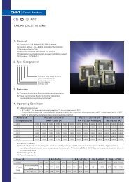
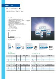
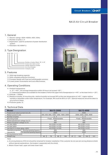
<strong>1.</strong> <strong>General</strong><br />
<strong>1.</strong>1 Electric ratings: 400A~4000A, 400V, 50Hz;<br />
<strong>1.</strong>2 Number of poles: 3, 4<br />
<strong>1.</strong>3 Application: used for protection of power distribution<br />
system;<br />
<strong>1.</strong>4 Standard: IEC 60947-<strong>2.</strong><br />
<strong>2.</strong> <strong>Type</strong> <strong>Designation</strong><br />
N A 15 - / <br />
<strong>3.</strong> <strong>Features</strong><br />
Number of poles; Blank: 3P; 4: 4P<br />
Frame size rated current<br />
Design sequence number<br />
<strong>Air</strong> circuit breaker<br />
Company code<br />
<strong>3.</strong>1 With high breaking capacity;<br />
<strong>3.</strong>2 With complete protection functions;<br />
<strong>3.</strong>3 Compact design with fixed and withdrawable versions;<br />
<strong>3.</strong>4 Lower power consumption and cost-effectiveness.<br />
4. Operating Conditions<br />
<strong>Circuit</strong> <strong>Breaker</strong>s<br />
<strong>NA15</strong> <strong>Air</strong> <strong>Circuit</strong> <strong>Breaker</strong><br />
4.1 Ambient temperature:<br />
a. -5 ~+40 , the average temperature within 24 hours not exceed +35 ;<br />
b. Customized breakers are available for the breaker of which the upper limit of temperature is =+40orthe lower limit is = -25 ;<br />
4.2 Altitude: 2000m;<br />
4.3 Relative humidity: At mounting site, relative humidity not exceed 50% at the max temperature of +40 ,<br />
higher relative<br />
humidity is allowable under lower temperature. For example, RH could be 90% at +20 .Special<br />
measures should be taken to<br />
occurrence of dews.<br />
4.4 Pollution grade: ;<br />
5. Technical Data<br />
Model<br />
<strong>NA15</strong>-2000 <strong>NA15</strong>-4000<br />
Frame level rated current Inm (A)<br />
2000<br />
4000<br />
Rated current In (A)<br />
400, 630, 800, 1000, 1250, 1600, 2000 2000, 2500, 3200, 4000<br />
Number of poles<br />
34 34 Mounting mode<br />
FixedWithdrawable FixedWithdrawable Rated operational voltage Ue (V)<br />
400<br />
400<br />
Rated insulation voltage Ui (V)<br />
690<br />
690<br />
Icu (kA) 400V<br />
50 (COS =0.25)<br />
80 (COS =0.2)<br />
Ics (kA) 400V<br />
40 (COS =0.25)<br />
60 (COS =0.2)<br />
Icw (kA) 0.4 s time-delay, 400V<br />
40 (COS =0.25)<br />
60 (COS =0.2)<br />
Operating properties Electrified operating frequency<br />
500<br />
500<br />
(operations)<br />
Un-electrified operating frequency<br />
4500<br />
2500<br />
Arcing distance (mm)<br />
0<br />
0<br />
Weight (kg)<br />
Note:<br />
46 76 69 108 87 164 102 191<br />
a. An arcing distance of 50 mm should be remained for breaker installation if the customer do not use zero arcing distance shield;<br />
without special explanations, the breaker is appended with the shield;<br />
b. Mode of down-lead: upper and lower down-lead.<br />
.3<strong>2.</strong>
<strong>Circuit</strong> <strong>Breaker</strong>s<br />
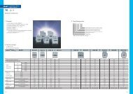
6. Product Overview<br />
13<br />
12<br />
5<br />
11<br />
10<br />
3<br />
6<br />
1<br />
8<br />
2<br />
4<br />
7<br />
.3<strong>3.</strong> .34.<br />
9<br />
<strong>NA15</strong> <strong>Air</strong> <strong>Circuit</strong> <strong>Breaker</strong><br />
1<br />
2<br />
3<br />
4<br />
5<br />
6<br />
7<br />
8<br />
9<br />
10<br />
11<br />
12<br />
13<br />
<strong>Breaker</strong> body<br />
Drawer support<br />
Panel<br />
Handle<br />
Intelligent controller<br />
Operating mechanism<br />
Auxiliary contact<br />
Arc-extinguishing chamber<br />
Secondary connecting part<br />
Shunt release<br />
Closing electro-magnet<br />
Electric motor<br />
Under-voltage release
7. Structure<br />
.35.<br />
<strong>Circuit</strong> <strong>Breaker</strong>s<br />
7.1 Front view of the body<br />
1<br />
2<br />
3<br />
4<br />
5<br />
6<br />
7<br />
8<br />
9<br />
10 11<br />
7.2 Drawer support<br />
Three operation statuses of the drawer are available:<br />
a. Making: both of the main circuit and secondary circuits are connected;<br />
b. Testing: the main circuit breaker breaks, only the secondary circuit is connected;<br />
c. Departure(Dis-connected): both of the main and secondary circuits are not connected.<br />
<strong>1.</strong> Zero-arcing shield<br />
<strong>2.</strong> Auxiliary contact (can see when taking)<br />
<strong>3.</strong> Handle<br />
4. Breaking pushbutton<br />
5. Making pushbutton<br />
6. Making & breaking indication<br />
7. Intelligent controller<br />
8. Energy-storage indication<br />
9. Drawer handle<br />
10. Indication of drawer support position<br />
1<strong>1.</strong> Drawer support
8. Intelligent Controller<br />
Intelligent controller is one of the core components of the circuit breaker;<br />
8.1 Properties of the intelligent controller<br />
a. Protective functions of over-load protection with long lim-delay, shortcircuit<br />
protection with short time-delay and invrse time limit, instantaneous<br />
operation protection.<br />
b. Single-phase grounding failure protection;<br />
c. Display of setting current Ir and operation current;<br />
d. Short-circuit alarm;<br />
e. Over-load alarm;<br />
f. Grounding failure protection alarm;<br />
g. Testing of operation properties<br />
8.2 Protection performances of intelligent controller<br />
a. Ir and its error of the controller<br />
Frame level rated<br />
current Inm (A)<br />
2000<br />
4000<br />
Long time-delay Ir1 Short time-delay Ir2 Instantaneous Ir3 Grounding failure protection<br />
Ir1 Error Ir2 Error Ir3 Error Ir4 Error<br />
(0.4~1) In<br />
b. Characteristic of long time-delay<br />
15% (3~10) In 15% (6~20) In 15% (0.2~0.8) In<br />
Note: When the breaker could realize long time-delay and overload, short-circuit and short time-delay, and short-circuit<br />
instantaneous protections, the setting ratings can not be over-lapped, and Ir1Ir2 Ir3;<br />
Ir1 <strong>1.</strong>05 Ir <strong>1.</strong>3 Ir <strong>1.</strong>5 Ir <strong>3.</strong>0 Ir1<br />
Operating time (s) 2h non-tripping 1h tripping 30, 60, 120, 240<br />
2 L L L<br />
15%<br />
Returnable time 8s,<br />
returnable current is 0.9Ir1<br />
Note: I2T L=(<strong>1.</strong>5Ir1)<br />
t (in the formula, T is the setting time at <strong>1.</strong>5 Ir1; Ir1 is the long time-delay setting current; T is long<br />
time-delay operation time). Error of the setting values is 15%.<br />
c. Characteristic of short time-delay<br />
The operation time is 0.2s and 0.4s, the error is 20%.<br />
d. Grounding failure protection<br />
The time-delay operation time at the grounding failure protection status is 0.2s and 0.4s, the error is 20%.<br />
e. OFF status is available for all the protection functions so as to the users could make selection on combination of different<br />
functions.<br />
9. Max. Manual operating force of the circuit breaker.<br />
Inm (A) Max. Operating force (manual) (N)<br />
2000<br />
4000<br />
200<br />
450<br />
.36.
.37.<br />
<strong>Circuit</strong> <strong>Breaker</strong>s<br />
10. Standard Composition of breaker<br />
To facilitate your ordering and utilization, the <strong>NA15</strong> air circuit breaker is appended with basic electric accessories as follows.<br />
Standard composition of the breaker Fixed version Withdrawable version<br />
Body<br />
Intelligent controller<br />
Drawer support<br />
Shunt release<br />
Under-voltage release<br />
Closing electro magnet<br />
Horizontal connection<br />
Electric motor<br />
Door frame<br />
Auxiliary contacts<br />
1<strong>1.</strong> Accessories<br />
1<strong>1.</strong>1 Under-voltage release<br />
a. Two types of the release are available: under-voltage instantaneous release and under-voltage<br />
release with time-delay, the delay time is 1s and 3s.<br />
b. Before operation of the circuit breaker, the under-voltage release should firstly be electrified;<br />
c. Ratings of under-voltage release<br />
Rated operational voltage Ue (V)<br />
Operational voltage<br />
Voltage for reliable making<br />
Voltage for reliable non-breaking<br />
Power consumption (W)<br />
<br />
<br />
<br />
<br />
<br />
<br />
<br />
<br />
<br />
AC400, AC230<br />
(35%~70%) Ue<br />
(85%~110%) Ue<br />
35%<br />
Ue<br />
40<br />
1<strong>1.</strong>2 Shunt release<br />
a. Shunt release is for remote breaking of circuit breaker so as to enhance security of the operator;<br />
b. Applicable to short time working system, long-time electrification is prohibited;<br />
c. Ratings of the release<br />
Rated operational voltage Ue(V)<br />
Operational voltage<br />
Power consumption<br />
Rated operational voltage Ue(V)<br />
Operational voltage<br />
Power consumption<br />
AC400<br />
AC400<br />
AC230<br />
AC230<br />
DC220<br />
(70%~110%) Ue<br />
57VA 44VA -<br />
DC220<br />
DC110<br />
1<strong>1.</strong>3 Closing electro-magnet<br />
a. The magnet is for remote making of circuit breaker so as to enhance security of the operator;<br />
b. Applicable to short time working system, long-time electrification is prohibited;<br />
c. Ratings of the magnet<br />
(85%~110%) Ue<br />
680VA 670VA<br />
-<br />
-<br />
DC110<br />
-
1<strong>1.</strong>4 Auxiliary contacts<br />
a. Auxiliary contact: 4NO+4NC or 6NO + 6NC breakers are available for customization;<br />
b. Utilization category: AC-15, DC-13;<br />
c. Ratings of auxiliary contact<br />
Rated voltage<br />
Us (V)<br />
AC 230V/400V<br />
DC220V<br />
1<strong>1.</strong>5 Doorframe<br />
a. For the purpose of enclosure;<br />
b. Protection degree up to IP40.<br />
Rated heating<br />
current Ith (A)<br />
6<br />
Rated control<br />
capacity<br />
300 VA<br />
60 W<br />
1<strong>1.</strong>6 Mechanical interlock<br />
a. For the interlock of two circuit breakers;<br />
b. The suitable distances between two breakers are: horizontal interlock, 2000 mm; vertical interlock, 900 mm.<br />
.38.
1<strong>1.</strong> Overall and Mounting Dimensions & holes dimensions of the doorframe<br />
.39.<br />
<strong>Circuit</strong> <strong>Breaker</strong>s<br />
1<strong>1.</strong>1 Withdrawable version circuit breaker, Inm=2000A.<br />
188.5<br />
146.5 10<strong>2.</strong>5<br />
D<br />
A<br />
280<br />
523<br />
224 93<br />
1<strong>1.</strong>2 Fixed version circuit breaker, Inm=2000A<br />
188.5<br />
A<br />
D<br />
473<br />
1<strong>1.</strong>3 Fixed version circuit breaker, Inm=4000A<br />
280<br />
D<br />
A<br />
280<br />
188.5<br />
12<strong>3.</strong>8<br />
523<br />
H<br />
H<br />
174 93<br />
H<br />
200 117<br />
289<br />
535<br />
256<br />
443<br />
302<br />
585( 3200A)<br />
535(<br />
2500A)<br />
94<br />
92<br />
5.5 37 64<br />
55<br />
59<br />
55<br />
55<br />
5.5 37 64<br />
3-pole<br />
4-pole<br />
In(A)<br />
400~1000<br />
1250~2000<br />
3-pole<br />
4-pole<br />
In(A)<br />
2000~2500<br />
3200<br />
4000<br />
3-pole<br />
4-pole<br />
A<br />
381<br />
471<br />
A<br />
344<br />
434<br />
A<br />
612<br />
712<br />
D<br />
300<br />
390<br />
H(mm)<br />
10<br />
16<br />
D<br />
309<br />
459<br />
H(mm)<br />
16<br />
20<br />
30<br />
D<br />
534<br />
634
1<strong>1.</strong>4 Withdrawable version circuit breaker. 4000A.<br />
D<br />
A<br />
145.8<br />
1<strong>1.</strong>5 Hole dimensions of doorframe<br />
a. Fixed version doorframe<br />
10-5 52<br />
19.5<br />
underside of breaker<br />
120.5 120.5<br />
19.5<br />
19.5<br />
280<br />
202<br />
188.5<br />
111<br />
111<br />
294<br />
A<br />
111<br />
Center of right side board<br />
installation hole of breaker<br />
473<br />
Inm<br />
2000A<br />
4000A<br />
117<br />
150<br />
A(mm)<br />
219<br />
240<br />
256<br />
493( 3200A)<br />
443( 2500A)<br />
59<br />
3-pole<br />
4-pole<br />
b. Withdrwable version doorframe<br />
436<br />
360<br />
120 120<br />
120.5 120.5<br />
19.5<br />
11<br />
202<br />
19.5<br />
14-5 B<br />
underside of breaker<br />
1<strong>2.</strong> Wiring<br />
The withdrawable version circuit breaker is equipped with 40 connection terminals.<br />
1<strong>2.</strong>1 Wiring diagram of withdrawable version breaker with pre-energy storage operation<br />
US1<br />
K1<br />
FU<br />
SB2<br />
71 72 73 74 75<br />
K1<br />
DF<br />
DT<br />
FD<br />
K1<br />
XK<br />
K1<br />
93 94<br />
M<br />
76<br />
DF<br />
H<br />
SB1 SB3 Us2 Us4<br />
95<br />
77 78 79 80<br />
F<br />
Q1<br />
Time delay<br />
device<br />
Q2<br />
SB4<br />
Auxiliary contact<br />
Us3<br />
+ - <br />
55<br />
294<br />
52<br />
51<br />
Center of right side board<br />
installation hole of breaker<br />
96 97 98 99 100 101 102 103 104 105 106 107 108 109 110 <br />
Grounding failure alarm<br />
92<br />
Overload alarm<br />
Short-circuit alarm<br />
81 82 3 84 85 86 87 88<br />
Common terminal<br />
Intelligent controller<br />
89 90<br />
In(A)<br />
2000~2500<br />
3200<br />
4000<br />
91<br />
XK<br />
A<br />
600<br />
700<br />
H(mm)<br />
16<br />
20<br />
30<br />
D<br />
575<br />
675<br />
Inm<br />
2000A<br />
4000A<br />
Pre-stored indicate<br />
92<br />
<br />
B(mm)<br />
197<br />
218<br />
.40.
.4<strong>1.</strong><br />
<strong>Circuit</strong> <strong>Breaker</strong>s<br />
1<strong>2.</strong>2 Wiring diagram of withdrawable version breaker without pre-energy storage operation<br />
Us1<br />
The fixed version (2000A, 4000A) circuit breaker is equipped with 36 connection terminals.<br />
1<strong>2.</strong>3 Wiring diagram of fixed version breaker with pre-energy storage operation<br />
Us1<br />
FU<br />
K1<br />
SB2<br />
SB1<br />
Us2 Us4<br />
65 66 67 68 69 70 71 72 73 74 75 76 <br />
1<strong>2.</strong>4 Wiring diagram of fixed version breaker without pre-energy storage operation<br />
Us1<br />
FU<br />
SB3<br />
SB4<br />
Us3<br />
+ - <br />
41 42 43 44 45 46 47 48 49 50 51 52 53 54 55 56 57 58 59 60 61 62 63 64 <br />
K1<br />
DF<br />
71 72 73 74 75 76 77 78 79 80 81 82 83 84 85 86 87 88 89 90 91 92 <br />
DF<br />
DF<br />
XK<br />
K1<br />
SB1<br />
XK<br />
K1 K1 K1<br />
FU<br />
DT<br />
K1<br />
M<br />
K1<br />
M<br />
DF<br />
SB3<br />
DF<br />
F<br />
Us2 Us4<br />
F<br />
Q1<br />
Time delay<br />
device<br />
Q2<br />
Q1<br />
Time delay<br />
device<br />
Q2<br />
SB4<br />
Us3<br />
+ - <br />
93 94 95 96 97 98 99 100 101 102 103 104 105 106 107 108 109 110 <br />
K1<br />
41<br />
DF<br />
K1<br />
SB1<br />
Auxiliary contact<br />
Auxiliary contact<br />
SB4<br />
65 66 67 68 69 70 71 72 73 74 75 76 <br />
Grounding failure alarm<br />
Overload alarm<br />
Short-circuit alarm<br />
DF<br />
Common terminal<br />
Intelligent controller<br />
Grounding failure alarm<br />
Overload alarm<br />
Short-circuit alarm<br />
Common terminal<br />
Intelligent controller<br />
Us3<br />
+<br />
-<br />
42 43 44 45 46 47 48 49 50 51 52 53 54 55 56 57 58 59 60 61 62 63 64<br />
XK<br />
K1<br />
K1<br />
M<br />
SB3 Us2 Us4<br />
DF<br />
F<br />
Q1<br />
Time delay<br />
device<br />
Q2<br />
Auxiliary contact<br />
Grounding failure alarm<br />
Overload alarm<br />
Short-circuit alarm<br />
Common terminal<br />
Intelligent controller<br />
DF<br />
DF<br />
DF<br />
XK<br />
<br />
Pre-stored indicate
Symbol<br />
SB1<br />
SB2<br />
SB3<br />
SB4<br />
Us1<br />
Us2<br />
Us3<br />
Us4<br />
M<br />
DT<br />
DF<br />
Q1<br />
Q2<br />
F<br />
K1<br />
XK<br />
FU<br />
<br />
Illumination<br />
Connected by user(broken line)<br />
Connected by manufacturer(real line)<br />
Pre-stored energy pushbutton<br />
ON pushbutton<br />
OFF pushbutton<br />
Emergent OFF pushbutton<br />
Power supply for motor and closing release<br />
Power supply for shunt release<br />
Power supply for intelligent controller<br />
Power supply for undervoltage release<br />
Electric motor<br />
Closing release<br />
Auxiliary contact<br />
Under voltage time-delay release<br />
Under voltage instantaneous release<br />
Shunt release<br />
Relay<br />
Change-over switch<br />
Fuse (10A)<br />
Secondary connecting terminal<br />
Note<br />
Prepared by the user<br />
Prepared by the user<br />
Prepared by the user<br />
Prepared by the user<br />
Power conherence<br />
Prepared by the user<br />
Note:<br />
# # # #<br />
a. " " indicates that if the control voltage is DC, terminals 83 -84 (or 53 -54 ) should be connected the output of the power<br />
module. It is strictly forbidden connected to the AC power supply.<br />
# # # #<br />
b. SB4 (Emergent pushbutton) is for user breaking breaker under emergency.81 -82 (or 51 -52 ) are connected by manufacturer<br />
before leaving factory. User should disconnect these terminals before connecting NC pushbutton.<br />
# # # # # # # #<br />
c. 86 -89 (or 56 -59 ) are the output-signal terminals of grounding failure alarm; 87 -89 (or 57 -59 ) are the output-signal<br />
# # # #<br />
terminals of overload alarm;88 -89 (or 58 -59 ) are the output-signal terminals of short-circuit alarm;<br />
.4<strong>2.</strong>