Skywatcher EQ8 Manual - First Light Optics
Skywatcher EQ8 Manual - First Light Optics
Skywatcher EQ8 Manual - First Light Optics

You also want an ePaper? Increase the reach of your titles
YUMPU automatically turns print PDFs into web optimized ePapers that Google loves.
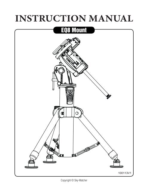
INSTRUCTION MANUAL<br />
<strong>EQ8</strong> Mount<br />
Copyright © Sky-Watcher<br />
100113V1
PART I : SETTING UP THE <strong>EQ8</strong> MOUNT<br />
PART II : POLAR ALIGNMENT<br />
PART III : ELECTRONIC CONTROL INTERFACE<br />
PART IV : OTHER FEATURES OF THE <strong>EQ8</strong> MOUNT<br />
APPENDIX I : SPECIFICATIONS<br />
CONTENT<br />
1.1 Setting Up the Tripod ...............................................................................................3<br />
1.2 Putting On the <strong>EQ8</strong> Mount .......................................................................................5<br />
1.3 Installing the Counterweights ..................................................................................6<br />
1.4 Installing the Telescope ...........................................................................................6<br />
1.5 Balancing the Mount Load .......................................................................................7<br />
2.1 Prepare the Mount for Polar Alignment ................................................................. 8<br />
2.2 Polar Alignment Using the SynScan Hand Controller ............................................ 9<br />
2.3 Polar Alignment with the Optional Polar Scope .................................................... 9<br />
2.4 The Orientation of the Polaris in Polar Scope .......................................................11<br />
2.5 Align the Polar Scope ...........................................................................................12<br />
3.1 Control Panel ........................................................................................................14<br />
3.2 Panel Interface Components ................................................................................14<br />
3.3 Pinout of the Interfaces .........................................................................................15<br />
3.4 Power Supply Requirements .................................................................................15<br />
4.1 Freedom Find Function .........................................................................................16<br />
4.2 Permanent Periodic Error Correction ....................................................................16<br />
4.3 Batch Exposures Function ....................................................................................16<br />
4.4 Auto-Home Function ............................................................................................16<br />
Dimensions ..................................................................................................................17<br />
Specifications ...............................................................................................................18<br />
2
1.1 Setting Up the Tripod<br />
PART I : SETTING UP THE <strong>EQ8</strong> MOUNT<br />
1. Fully expand the tripod legs on level ground.<br />
2. Install the hand control bracket on the tripod. (Fig 1.1a)<br />
3. Place one or two counterweight(s) just between the bottom of the central post and the<br />
ground if there is enough space between them. This is a critical safety effort because the<br />
counter weight(s) will prevent users from putting their feet under the central post unconsciously.<br />
(Fig. 1.1b)<br />
Hand Control<br />
Bracket<br />
M3X10<br />
Screws<br />
Fig. 1.1a<br />
Fig. 1.1b<br />
3. Fully release the clamp of the central post by loosening the two hex nuts on it with a 19mm<br />
hex wrench (Fig 1.1c).<br />
• The central post might fall freely when the two nuts are loosened. The counterweight(s),<br />
which is (are) placed between the bottom of the central post and the ground earlier, will<br />
support the central post and prevent any potential damages in such case.<br />
• While loosening the two clamp nuts, to reduce the possible impact of the falling of the<br />
central post, it is recommended to hold the tripod top, or to fill the gap between the top<br />
of the counter weight and the bottom of central post with some soft material.<br />
• User should loosen the two hex nuts alternately to make sure both of them are fully<br />
loosened.<br />
Dowel<br />
Central Post<br />
Align<br />
Clamp<br />
Nuts<br />
4. After the clamp is fully released, rotate the central post in the clamp to roughly align the<br />
dowel on the tripod top with the gap of the clamp. (Fig 1.1c)<br />
3<br />
Fig. 1.1c
PART I: SETTING UP THE <strong>EQ8</strong> MOUNT<br />
5. Assemble the 3 adjustable spider trusses as shown in Fig 1.1d and Fig 1.1e. Do not tighten<br />
the thumb screws at this moment.<br />
Thumb Screw<br />
Spider Truss<br />
See Fig. 1.4<br />
6. Slide the central post up/down in the clamp (Fig. 1.1c) to the proper height and then tighten<br />
the 3 thumb screws on the spider trusses to prevent the central post from falling.<br />
7. Tighten both hex nuts on the clamp to secure the central post in the clamp. The two nuts<br />
MUST be tightened in an alternate manner to avoid damage to the clamp. Do not over<br />
tighten the two nuts.<br />
8. The tripod can be placed directly on a level ground, or it can be placed on the 3 adjustable<br />
stands as shown in Fig 1.1f.<br />
• Put the tips of the tripod on the three adjustable stands.<br />
• Turn the leveling screw to raise/lower a leg.<br />
• Tighten the locking ring when the tripod top is leveled. (Fig. 1.1d).<br />
Fig. 1.1d Fig. 1.1e<br />
• The small holes at the side of the leveling screw and the locking ring can accept a metal<br />
bar for turning the screw and the ring.<br />
Leveling Screw<br />
Locking Ring<br />
Adjustable Stands<br />
Fig. 1.1f<br />
4
PART I: SETTING UP THE <strong>EQ8</strong> MOUNT<br />
1.2 Putting On the <strong>EQ8</strong> Mount<br />
1. Loosen the two azimuth adjustment knobs on the <strong>EQ8</strong> mount until there is sufficient space<br />
between the two knob screws (Fig. 1.2a). Remove the two azimuth locking screws and<br />
washers on the tripod top.<br />
2. Align the metal dowel on the tripod top with the gap between the two azimuth adjustment<br />
knobs; and then put the mount on the tripod top. (Fig 1.2b)<br />
Azimuth<br />
Locking<br />
Screw<br />
*<br />
*<br />
Dowel<br />
Loosen<br />
Loosen<br />
*<br />
Azimuth Adjustment Knobs<br />
Fig. 1.2a<br />
Fig. 1.2b<br />
3. Apply the two azimuth locking screws with washers to slightly fix the mount on the tripod<br />
top. (Fig. 1.2c). Do not tighten these screws yet.<br />
4. Turn the primary locking knob in clockwise direction to engage the primary locking shaft to<br />
the threaded hole at the center of the mount’s bottom. Turn the knob until it is tightened.<br />
(Fig 1.2c)<br />
Azimuth Locking Screw<br />
Primary Locking shaft<br />
5<br />
Primary Locking Knob<br />
Fig. 1.2c
PART I: SETTING UP THE <strong>EQ8</strong> MOUNT<br />
6. Slide the jackscrew handle in the hole at the end of the jackscrew shaft. Apply two ball<br />
head screws on the handle. (Fig. 1.2d)<br />
Ball-head Screw<br />
Jackscrew Shaft<br />
Counterweight Shaft<br />
1.3 Installing the Counterweights<br />
1. Screw the counterweight rod into the mount as shown in Fig. 1.3a.<br />
2. Remove the stopper cap at the end of the counterweight rod.<br />
Fig. 1.2d<br />
3. Loosen the counterweight’s thumb screw and slide the counterweight onto the counterweight<br />
rod. Retighten the thumb screw to secure the counterweight on the rod. (Fig. 1.3b)<br />
4. Replace the stopper cap to the end of the counterweight rod.<br />
Lock<br />
Counterweight<br />
Rod<br />
Stopper Cap<br />
Thumb Screw<br />
1.4 Installing the Telescope<br />
Fig. 1.3a Fig. 1.3b<br />
1. Before installing a telescope, ensure:<br />
• The counterweight rod is pointing towards the ground.<br />
• All counterweights have been moved to the end of the counterweight rod.<br />
• The R.A. Axis is secured by tightening the R.A. Clutch. (Fig. 1.4)<br />
6
PART I: SETTING UP THE <strong>EQ8</strong> MOUNT<br />
2. Release the Dec. clutch knob (Fig 1.4) and rotate the Dec. axis until the three knobs on<br />
the saddle are facing upward and the dovetail groove is leveled (Fig 1.4). Tighten the<br />
Dec. clutch again.<br />
Saddle<br />
Arrow Sign<br />
Dec. Clutch<br />
R.A. Clutch<br />
Fig. 1.4<br />
3. Loosen the three knobs on the saddle alternately until the width of groove is slightly wider<br />
than the width of the dovetail bar on the telescope.<br />
4. While holding the telescope horizontally, seat or slide the dovetail bar of the telescope to<br />
the groove of the saddle. The pointing direction of the telescope should match the arrow<br />
sign on the saddle (Fig 1.4).<br />
5. Tighten the three knobs alternately to secure the dovetail bar in the groove.<br />
Warning: Keep supporting the telescope until you are sure that it has been firmly attached<br />
to the saddle.<br />
1.5 Balancing the Mount<br />
Once the counterweight and the telescope have been installed, the mount should be balanced<br />
to reduce stress on the motor drive system, as well as to ensure smooth and accurate operation.<br />
1. Loosen the R.A. clutch and rotate the R.A. axis until the counterweight rod is parallel to the<br />
ground. Tighten the R.A. clutch.<br />
2. Loosen the Dec. clutch and rotate the Dec. axis until the telescope is parallel to the ground.<br />
Tighten the Dec. clutch.<br />
3. Loosen the thumb screws on the counterweights.<br />
4. Hold the counterweight rod with one hand, release the R.A. clutch and adjust the counterweights<br />
along the rod until the mount is able to remain stationary without support. Tighten<br />
the thumb screws on the counterweights again.<br />
5. Rotate the R.A. axis; the mount should remain relatively balanced along different angles.<br />
Once this is confirmed, return the mount to its original position described in Step 1 and<br />
tighten the R.A. clutch again.<br />
6. Hold the telescope with one hand and release the Dec. clutch.<br />
7. Slowly let go of the telescope and check for any rotational movements. If there is a<br />
movement, slide the dovetail bar in the saddle to find a balancing position at which the<br />
telescope can remain stationary without support.<br />
7
2.1 Prepare the Mount for Polar Alignment<br />
PART II : POLAR ALIGNMENT<br />
Prior to operating the <strong>EQ8</strong> mount, it must be polar-aligned.<br />
1. Set up the <strong>EQ8</strong> mount, counterweights, and telescope as described in PART I. It is recommended<br />
to polar-align the <strong>EQ8</strong> mount with all equipments installed.<br />
2. Loosen the primary locking knob and both azimuth locking screws; and then use the azimuth<br />
adjustment knobs to put the azimuth locking screws to the middle of the slots (Fig<br />
2.1a). Tighten the azimuth locking screws slightly.<br />
Azimuth locking screw<br />
Slot<br />
Azimuth adjustment<br />
knob<br />
Fig. 2.1a<br />
3. Loosen the fork gripping knobs and screws (Fig 2.1b) on both sides of the <strong>EQ8</strong> mount, and<br />
then tighten them slightly.<br />
4. Tighten the primary locking knob and then release it for 1/4 turn.<br />
5. Move the tripod to align the R.A. axis to true north or south (for observing in southern hemisphere)<br />
roughly.<br />
6. Install the handle on the jackscrew and use the altitude jackscrew to set the latitude dial<br />
reading local latitude (Fig 2.1b).<br />
Latitude Dial<br />
Fork Gripping Screw<br />
Fork Gripping Knob<br />
Latitude Jackscrew<br />
8<br />
Jackscrew Handle<br />
Fig. 2.1b
PART II: POLAR ALIGNMENT<br />
2.2 Polar Alignment Using the SynScan Hand Controller<br />
1. Choose 2-Star alignment or 3-Star alignment to align the mount, and then perform the polar-alignment<br />
routine. Repeat these operations several times until the SynScan hand controller<br />
reports small polar alignment error after the 2-Star alignment or 3-Star alignment.<br />
Refer to SynScan hand controller’s manual for detail operation instruction.<br />
2. At the end of the polar-alignment routine, tighten the primary locking knob, and then tighten<br />
the azimuth locking screws, the fork gripping knobs and screws. User should observe<br />
the alignment star in the eyepiece while alternately tightening these symmetric knobs and<br />
screws; try to minimize the movement of the alignment star in the eyepiece.<br />
3. It is recommended to remove the jackscrew handle after the polar-alignment has finished.<br />
It can prevent unexpected changes to the polar-alignment.<br />
2.3 Polar Alignment with the Optional Polar Scope<br />
1. Install the polar scope assembly on the <strong>EQ8</strong> mount as shown in Fig 2.3a.<br />
Large knurled<br />
ring<br />
Fig. 2.3a<br />
2. Verify whether the polar scope is aligned with the R.A. Axis. (Refer to the upcoming section<br />
“Align the Polar Scope”).<br />
3. Find the orientation of Polaris in Polar Scope. (Refer to the upcoming section “Orientation<br />
of Polaris in Polar Scope”).<br />
4. Use the latitude jackscrew and the azimuth adjustment knobs to polar-align the mount:<br />
• Fig 2.3b shows the pattern in the field of view (FOV) of the polar scope. If the image<br />
appears blurred, rotate the knurled ring of the polar scope’s eyepiece to focus.<br />
9
PART II: POLAR ALIGNMENT<br />
Fig. 2.3b<br />
• For observing in Northern Hemisphere: Find the Polaris (The brightest star near the<br />
North Celestial Pole) in the polar scope; then use the jackscrew and the two azimuth<br />
adjustment knobs to move the Polaris to the proper position in the FOV of the polar<br />
scope. (Refer to the upcoming section “The Orientation of Polaris in Polar Scope”).<br />
• For observing in Southern Hemisphere: In the FOV of the polar scope, locate the 4<br />
dim stars (Around Magnitude 5 to 6) which form the pattern like the “Octans” drawing<br />
in the polar scope (refer to Fig. 2.3b). Rotate the large knurled ring of the polar scope<br />
assembly to align the orientation of the “Octans” drawing to the 4 stars. Then use the<br />
jack screw and the azimuth adjustment knobs to move the 4 stars to the 4 small circles<br />
of the “Octans” drawing.<br />
5. Tighten the primary locking knob, and then tighten the azimuth locking screws, the fork<br />
gripping knobs and screws.<br />
6. It is recommended to remove the jackscrew handle after the polar-alignment has finished.<br />
It can prevent unexpected changes to the polar-alignment.<br />
10
PART II: POLAR ALIGNMENT<br />
2.4 The Orientation of the Polaris in Polar Scope<br />
As the Polaris is not located exactly at the North Celestial Pole, we can see it orbits the North<br />
Celestial Pole in a polar scope. The large circle seen in the center of the pattern in Fig. 2.3b is<br />
a representation of the Polaris’ orbit around the North Celestial Pole. When performing the polar<br />
alignment process, it is necessary to determine the orientation of the Polaris on the circle.<br />
We can use the following 3 methods to get the orientation:<br />
1. Locate Ursa Major (Big Dipper) in the sky, or alternatively Cassiopeia. Tighten the R.A.<br />
clutch again. Rotate the large knurled ring of the polar scope assembly until either the Big<br />
Dipper or Cassiopeia is aligned with their pattern in the FOV of the polar scope. At this<br />
point, the location of the small circle on the large central circle of the pattern represents the<br />
orientation of the Polaris in the polar scope. Put the Polaris to the center of the small circle<br />
to finish the polar alignment.<br />
2. Locate both the Polaris and the Kochab in the sky near the North Celestial Pole. The direction<br />
from the Polaris to the Kochab can be used as proximity of the orientation of the<br />
Polaris in the polar scope. Put the Polaris to the same direction on the large central circle<br />
in the polar scope to finish the polar alignment.<br />
3. At the end of the initialization of the SynScan hand control, after entering the proper local<br />
longitude, latitude, date, time, and daylight-saving time, the SynScan hand controller will<br />
display the message: “Polaris Position in P.Scope=HH:MM”. Imagine the larger circle in Fig.<br />
2.3b as a clock’s face with 12:00 at the top, with the current time pointing to the “HH:MM”. The<br />
orientation of the hour hand of the clock represents the orientation of the Polaris in the polar<br />
scope. Put the Polaris to the same orientation on the large circle to finish the polar alignment.<br />
Tips: To find the top of the large circle in FOV of the polar scope, use the latitude jackscrew to<br />
move the Polaris close to the top of the circle, and then use the azimuth adjustment knobs to move<br />
the Polaris in the FOV horizontally. The middle point of the arc which was cut by the horizontal track<br />
of the Polaris is the top of the large circle (Fig 2.4).<br />
Arc<br />
Top Point<br />
Horizontal track of the Polaris<br />
Fig. 2.4<br />
Out of the three methods above, the first two methods are somewhat less accurate, while the<br />
orientation given by the SynScan hand controller is the most accurate.<br />
11
PART II: POLAR ALIGNMENT<br />
2.5 Align the Polar Scope<br />
Before using the polar scope for polar alignment, the polar scope itself must be calibrated to<br />
ensure the pattern in the polar scope is aligned to the mount’s R.A. axis. This includes two<br />
calibration routines:<br />
Routine 1 - Align the pattern plate to the rotating axis of the polar scope<br />
1. Choose a fixed object (the Polaris at night, or a faraway object in daytime); put the reticle<br />
in the FOV of the polar scope on the object by adjusting the two azimuth adjustment knobs<br />
and the latitude jackscrew of the <strong>EQ8</strong> mount. Tighten the R.A. axis.<br />
2. Rotate the large knurled ring on the polar scope for exactly half a turn (Fig 2.5a).<br />
Large knurled<br />
ring<br />
Fig. 2.5a<br />
3. If the object remains at the center of the reticle in the polar scope after the rotation, then it<br />
means the polar scope’s pattern plate has been aligned to the polar scope’s rotating axis<br />
and no calibration is needed.<br />
4. If the object deviates from the reticle, then use a 1.5mm Allen wrench to adjust the three<br />
small Allen screws on the polar scope (Fig. 2.5b) to eliminate the deviation to HALF. (Fig.<br />
2.5c)<br />
Fig. 2.5b Fig. 2.5c<br />
6. Repeat steps 1-4 a few times until the object keeps at the center of the reticle when rotating<br />
the mount in R.A. axis<br />
12
PART II: POLAR ALIGNMENT<br />
Note:<br />
• When adjusting the Allen screws, loosen one screw only ¼ of a turn, and then tighten the<br />
other two.<br />
• Do not over tighten the Allen screws; it might damage the pattern plate in the polar scope.<br />
• Do not loosen one screw completely or loosen more than one screw at a time; otherwise,<br />
the pattern plate in the polar scope will be disengaged and further adjustment is impossible.<br />
• If the pattern plate does disengage, remove the polar scope’s eyepiece by turning the<br />
knurled ring counterclockwise and then engage the pattern plate again.<br />
Routine 2 - Align the rotating axis of the polar scope to the R.A. axis of the mount<br />
1. Release the R.A. clutch and level the counterweight rod, then lock the R.A. clutch again.<br />
2. Choose a fixed object (the Polaris at night, or a faraway object in daytime); put the reticle<br />
in the FOV of the polar scope on the object by adjusting the two azimuth adjustment knobs<br />
and the latitude jackscrew of the <strong>EQ8</strong> mount.<br />
3. Rotate the mount in R.A. axis for half a turn exactly. Tighten the R.A. clutch after the rotation.<br />
4. If the object remains at the center of the reticle in the polar scope after the rotation, then it<br />
means the polar scope’s rotating axis has been aligned to the R.A. axis and no calibration<br />
is needed.<br />
5. If the object deviates from the reticle, then adjust the three small adjustment screws as<br />
shown in Fig. 2.5d to eliminate the deviation to HALF.<br />
Adjustment<br />
Screws<br />
Fig. 2.5d<br />
6. Repeat steps 1-5 a few times until the object keeps at the center of the reticle when rotating<br />
the mount in R.A. axis<br />
13
PART III : ELECTRONIC CONTROL INTERFACE<br />
3.1 Control Panel<br />
The control panel of the <strong>EQ8</strong> Mount is shown below:<br />
Fig. 3.1<br />
3.2 Panel Interface Components:<br />
POWER: This is an outlet from which the mount and the hand control get power<br />
supply. To connect to a power supply, align the index on both the plug of the cord<br />
and the outlet on the panel, and then insert the plug to the outlet. Tighten the<br />
knurled cap on the plug to secure the plug on the panel.<br />
AUTO GUIDE: This RJ-12 6-pins outlet is for connecting an autoguider. It is compatible<br />
with any autoguider with a ST-4 type interface.<br />
HAND CONTROL: This RJ-45 8-pins outlet is for connecting the SynScan hand<br />
controller.<br />
SNAP:This is a stereo outlet for connecting to a camera’s shutter control port. The<br />
SynScan hand control can control a camera to take pictures automatically via this<br />
interface.<br />
POWER Switch: Turns on and off the power to the mount and hand controller.<br />
The power LED on the power switch serves as a power-on indicator and provides<br />
other statuses.<br />
1. Steady on: Power voltage is normal.<br />
2. Slow flashing: Power voltage is low; continuing to operate the mount may damage<br />
the battery (if a 12V lead-acid battery is in use).<br />
3. Fast flashing: Power voltage is extremely low; continuing to operate the mount<br />
may damage the battery and the motor controller in the mount.<br />
14
PART III: ELECTRONIC CONTROL INTERFACE<br />
3.3 Pinout of the Interfaces:<br />
4. Intermittent one flash: The PPEC training routine has been triggered, but the<br />
controller in the mount has not received the worm index signal and the correction-recoding<br />
has not started yet.<br />
5. Intermittent two flashes: The PPEC training routine has been started and the<br />
controller in the mount has received the worm index signal and started to record<br />
the PE correction. When the intermittent two flashes stops, it means the PPEC<br />
training has finished.<br />
6. Intermittent, three flashes: Sidereal tracking with PEC is now enabled.<br />
GND<br />
Vpp+<br />
Vpp+<br />
RX(3.3V)<br />
TX(3.3V)<br />
GND<br />
RA-<br />
DEC-<br />
DEC+<br />
RA+<br />
GND<br />
+5V<br />
HAND CONTROL<br />
8<br />
7<br />
6<br />
5<br />
4<br />
3<br />
2<br />
1<br />
6<br />
5<br />
4<br />
3<br />
2<br />
1<br />
TRIGGER<br />
GND<br />
DELAYED<br />
TRIGGER<br />
R<br />
560<br />
C<br />
10uF/25V<br />
Internal Circuit<br />
Optoisolator<br />
GND<br />
Control Signal<br />
POWER<br />
AUTO GUIDE<br />
SNAP<br />
Note:<br />
Fig. 4.3<br />
• The SNAP port provides two trigger signals to the stereo plug. The signal to the head of the<br />
plug is issued slightly later than the signal to the ring of the plug.<br />
• For a camera which only needs a shutter-release signal, either trigger signals will work. For<br />
a camera which requires a “Focus” signal ahead of the shutter-release signal, both signals<br />
should be connected properly.<br />
• The camera control cable shipped with the AZ-EQ6 GT mount is for a Canon EOS series<br />
DSLR camera. Cable for other cameras is optional and can be ordered separately.<br />
3.4 Power Supply Requirements<br />
• Output Voltage: DC 11V (minimum) to DC 16V (maximum). Voltage not in this range might<br />
cause permanent damage to the motor controller or the hand controller.<br />
• Output Current: 4A for power supply with 11V output voltage, 2.5A for power supply with<br />
16V output voltage.<br />
• Do not use an un-regulated AC-to-DC adapter. When choosing an AC adapter, it is recommended<br />
to use a switching power supply with 15V output voltage and at least 3A output<br />
current.<br />
• If the power voltage is too low, the motor controller will stop the motors automatically.<br />
15
PART IV : OTHER <strong>EQ8</strong> MOUNT FEATURES<br />
4.1 Freedom Find TM Function<br />
The <strong>EQ8</strong> mount is equipped with auxiliary encoders on both the R.A. axis and Dec. axis.<br />
Therefore, the mount can keep tracking its current position even when a user unlocks the<br />
clutches and rotates the mount in R.A. axis and Dec. axis manually.<br />
With this feature, a user can manually operate the mount anytime without worrying about losing<br />
the mount’s alignment status. When the user wants to operate the mount with the SynScan<br />
hand control again, no alignment is required and all that is needed to be done is to re-lock the<br />
clutches.<br />
This feature can be enabled or disabled on the SynScan hand controller.<br />
4.2 Permanent Periodic Error Correction<br />
The <strong>EQ8</strong> mount is equipped with an index on its R.A. worm thus the motor controller can<br />
keep tracking the current position of the worm. After a proper PEC training routine, in which<br />
the training data is stored in the motor controller permanently, a user can start the periodic<br />
error correction (PEC) at any time to improve the tracking performance for short focal length<br />
astrophotography. A training process is not required in the next observing session (assuming<br />
that the polar alignment is always accurate), thus this is a Permanent Period Error Correction<br />
(PPEC). A user can train the mount with manual guiding or auto-guiding. For detailed instructions,<br />
please refer to the relevant section in the SynScan hand controller instruction manual.<br />
4.3 Batch Exposures Function<br />
The <strong>EQ8</strong> mount is equipped with a SNAP port which can control the shutter release of a<br />
camera. Working with the SynScan hand control’s “Camera Control” function, a user can take<br />
batch exposures when doing astrophotography. Up to 8 groups of “Exposure-time & Frames”<br />
combinations can be set on the SynScan hand controller. For detailed information, refer to the<br />
SynScan hand control’s instruction manual.<br />
4.4 Auto-Home Function<br />
The <strong>EQ8</strong> mount is equipped with two home position sensors. Working with the SynScan hand<br />
controller, the mount can be placed to the same home position after turning on the power. For<br />
detailed information, refer to the SynScan hand control’s instruction manual.<br />
16
APPENDIX I : SPECIFICATIONS<br />
Dimensions:<br />
Ø180<br />
Ø140<br />
473<br />
45°<br />
800~1100<br />
360<br />
Mount<br />
272<br />
Mount<br />
894<br />
Tripod<br />
M12<br />
54<br />
2-Ø 6<br />
4-M 6<br />
76<br />
Ø 124<br />
160<br />
Mount Bottom Plate<br />
76<br />
100<br />
Saddle Head<br />
17
APPENDIX I : SPECIFICATIONS<br />
Specifications:<br />
Product Name<br />
Mount Type<br />
Payload (Counterweights excluded)<br />
<strong>EQ8</strong> Mount<br />
German Equatorial Mount<br />
50kg<br />
Latitude Adjustment Range 10º to 65º<br />
Azimuth Adjustment Range ±10 º<br />
Weight (Tripod excluded)<br />
Counterweight<br />
Tripod<br />
Counterweight Rod<br />
Power Requirement<br />
Motor<br />
Transmission<br />
25 kg<br />
2 x 10kg/ea<br />
29.4kg<br />
2.6kg<br />
DC11~16V 4A<br />
0.9 º Hybrid Stepper Motor<br />
435:1 Worm Drive + 64 Micro-step/0.9º Stepper Motor Drive<br />
Gear Ratio 435<br />
Resolution<br />
Maximum Slewing Speed<br />
Tracking Rate<br />
Tracking Mode<br />
Auto-guiding Speed<br />
PEC<br />
Hand Controller<br />
Database<br />
Celestial Object Catalog<br />
Pointing Accuracy<br />
Resolution of Aux. R.A./Dec. Axis Encoders<br />
Note: The above specifications may be changed without advance notice.<br />
11136000 Counts/Rev., approx. 0.12 arc-second<br />
3.3 degrees/second<br />
Sidereal rate, solar rate, lunar rate<br />
Equatorial mode<br />
0.125X, 0.25X, 0.5X, 0.75X, 1X<br />
100 Segments Permanent PEC<br />
SynScan<br />
42000+ Objects<br />
Messier, NGC, IC, SAO, Caldwell, Double Star,<br />
Variable Star, Named Star, Planets<br />
Up to 5 arc-minutes (RMS)<br />
17624 Counts/Rev., approx. 1.2 arc-minutes<br />
18
<strong>EQ8</strong> Mount