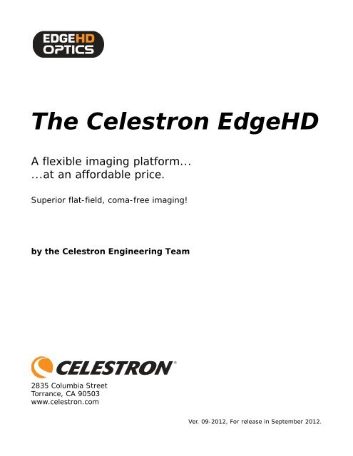
Celestron EdgeHD White Paper - First Light Optics
Celestron EdgeHD White Paper - First Light Optics
Celestron EdgeHD White Paper - First Light Optics

Create successful ePaper yourself
Turn your PDF publications into a flip-book with our unique Google optimized e-Paper software.
The <strong>Celestron</strong> <strong>EdgeHD</strong><br />
A flexible imaging platform...<br />
...at an affordable price.<br />
Superior flat-field, coma-free imaging!<br />
by the <strong>Celestron</strong> Engineering Team<br />
2835 Columbia Street<br />
Torrance, CA 90503<br />
www.celestron.com<br />
Ver. 09-2012, For release in September 2012.
The <strong>Celestron</strong> <strong>EdgeHD</strong><br />
A Flexible Imaging Platform<br />
at an Affordable Price<br />
By the <strong>Celestron</strong> Engineering Team<br />
Abstract: The <strong>Celestron</strong> <strong>EdgeHD</strong> is an advanced, flat-field, aplanatic series of telescopes<br />
for visual observation and imaging with astronomical CCD cameras and full-frame digital<br />
SLR cameras. This paper describes the development goals, design decisions, optical<br />
performance, and their practical realization in 8-, 9.25-, 11-, and 14-inch apertures. We<br />
include cross-sections of the <strong>EdgeHD</strong> series, comparative spot diagrams for the <strong>EdgeHD</strong><br />
and competing “coma-free” Schmidt-Cassegrain designs, a table with specifications for<br />
visual and imaging, graphics showing how to place sensors at the optimum back-focus<br />
distance, and details on the construction and testing of the <strong>EdgeHD</strong> telescope series.<br />
1. Introduction<br />
The ʺclassicʺ Schmidt‐Cassegrain telescope manufactured<br />
by <strong>Celestron</strong> served an entire generation of<br />
observers and astrophotographers. With the advent of<br />
wide‐field and ultra‐wide field eyepieces, large‐format<br />
CCD cameras, and full‐frame digital SLR cameras, the<br />
inherent drawbacks of the classic SCT called for a new<br />
design. The <strong>EdgeHD</strong> is that new design. The <strong>EdgeHD</strong><br />
offers clean, diffraction‐limited images for high‐power<br />
observation of the planets and the moon. And, as an<br />
aplanatic flat‐field astrograph, the <strong>EdgeHD</strong>ʹs optics<br />
provide tight, round, edge‐to‐edge star images over a<br />
wide, 42 mm diameter, flat field of view for stunning<br />
color, monochrome, and narrow‐band imaging of<br />
deep‐sky objects.<br />
2. Setting Goals for the <strong>EdgeHD</strong> Telescope<br />
The story of the <strong>EdgeHD</strong> began with our setting<br />
performance goals, quality goals, and price goals. Like<br />
the classic SCT, the new <strong>Celestron</strong> optic would need to<br />
be light and compact. Optically, we set twin goals: the<br />
new telescope would be capable of extraordinary<br />
wide‐field viewing with advanced eyepiece designs,<br />
and it would be capable of sharp‐to‐the‐edge astrophotography<br />
with advanced digital SLR cameras and<br />
astronomical CCD cameras. Cost wise, we wanted to<br />
leverage <strong>Celestron</strong>ʹs proven ability to manufacture<br />
high‐performance telescopes at a user‐friendly price<br />
point. In short, our goal was to offer observers a flexible<br />
imaging platform at a very affordable price.<br />
Given an unlimited budget, engineering high‐performance<br />
optics is not difficult. The challenge<br />
<strong>Celestron</strong> accepted was to control the price, complexity,<br />
and cost of manufacture without compromise to<br />
optical performance. We began with a comprehensive<br />
review of the classic SCT and possible alternatives.<br />
Our classic SCT has three optical components: a<br />
spherical primary mirror, a spherical secondary mirror,<br />
and a corrector plate with a polynomial curve. As<br />
every amateur telescope maker and professional optician<br />
knows, a sphere is the most desirable optical figure.<br />
In polishing a lens or mirror, the work‐piece<br />
moves over a lap made of optical pitch that slowly conforms<br />
to the glass surface. Geometrically, the only surfaces<br />
that can slide freely against one another are<br />
spheres: any spot that is low relative to the common<br />
spherical surface receives no wear; any spot that is high<br />
relative is worn off. Spherical surfaces result almost<br />
automatically.<br />
A skilled optician in a well‐equipped optical shop<br />
can reliably produce near‐perfect spherical surfaces.<br />
Furthermore, by comparing an optical surface against a<br />
matchplate—a precision reference surface—departures<br />
in both the radius and sphericity can be quickly<br />
assessed. In forty years of manufacturing its classic<br />
Schmidt Cassegrain telescope, <strong>Celestron</strong> had fully<br />
mastered the art of making large numbers of essentially<br />
perfect spherical primary and secondary mirrors.<br />
In addition, <strong>Celestron</strong>’s strengths included the production<br />
of Schmidt corrector plates. In the early 1970s,<br />
Tom Johnson, <strong>Celestron</strong>ʹs founder, perfected the necessary<br />
techniques. Before Johnson, corrector plates like<br />
that on the 48‐inch Schmidt camera on Palomar Mountain<br />
cost many long hours of skilled work by master<br />
opticians. Johnsonʹs innovative production methods<br />
made possible the volume production of a complex<br />
and formerly expensive optical component—and triggered<br />
the SCT Revolution of the 1970s.<br />
The <strong>EdgeHD</strong> by <strong>Celestron</strong> 2
Edge HD 800<br />
Edge HD 925<br />
Edge HD 1100<br />
Edge HD 1400<br />
Figure 1. <strong>Celestron</strong>’s <strong>EdgeHD</strong> series consists of four<br />
aplanatic telescopes with 8-, 9.25-, 11-, 14-inch<br />
apertures. The optical design of each instrument has<br />
been individually optimized to provide a focal plane<br />
that is coma-free, flat, and produces sharp images to<br />
the edge of the view with minimal vignetting.<br />
The <strong>EdgeHD</strong> by <strong>Celestron</strong> 3
Optical Aberrations<br />
For those not familiar with the art of optical<br />
design, this brief primer explains what<br />
aberrations are and how they appear<br />
in a telescopic image.<br />
Off-Axis Coma<br />
Coma is an off-axis aberration that results<br />
when the rays from successive zones are<br />
displaced outward relative to the principal<br />
(central) ray. A star image with coma appears<br />
to have wispy “hair” or little “wings” extending<br />
from the image. In a coma-free optical system,<br />
rays from all zones are centered on the central<br />
ray, so stars appear round across the field.<br />
Field Curvature<br />
Field curvature occurs when the best off-axis<br />
images in an optical system focus ahead or<br />
behind the focused on-axis image. The result<br />
is that star images in the center of the field of<br />
view are sharp, but off-axis images appear more<br />
and more out of focus. A telescope with no field<br />
curvature has a “flat field,” so images are sharp<br />
across the whole field of view.<br />
Spherochromatism<br />
In the Schmidt Cassegrain, spherochromatism<br />
is present, but not deleterious in designs with<br />
modest apertures and focal ratios. It occurs<br />
because the optical “power” of the Schmidt<br />
corrector plate varies slightly with wavelength.<br />
Only in very large apertures or fast SCTs does<br />
spherochromism become a problem.<br />
For more than forty years, the classic SCT satisfied<br />
the needs of visual observers and astrophotographers.<br />
Its performance resulted from a blend of smooth spherical<br />
surfaces and Johnson’s unique method of producing<br />
the complex curve on the corrector with the same<br />
ease as producing spherical surfaces. As the 21st Century<br />
began, two emerging technologies—wide‐field<br />
eyepieces and CCD cameras—demanded high‐quality<br />
images over a much wider field of view than the classical<br />
SCT could provide.<br />
Why? The classic SCT is well corrected optically for<br />
aberrations on the optical axis, that is, in the exact center<br />
of the field of view. Away from the optical axis,<br />
however, its images suffer from two aberrations: coma<br />
and field curvature. Coma causes off‐axis star images to<br />
flare outward; field curvature causes images to become<br />
progressively out of focus away from the optical axis.<br />
As wide‐field eyepieces grew in popularity, and as<br />
observers equipped themselves with advanced CCD<br />
cameras, the classic SCT proved inadequate. To meet<br />
the requirements of observers, we wanted the new<br />
<strong>Celestron</strong> optics to be both free of coma and to have<br />
virtually zero field curvature.<br />
3. Engineering a New Astrograph<br />
We did not take lightly the task of improving the<br />
classic SCT. Its two spherical mirrors and our method<br />
of making corrector lenses allowed us to offer a highquality<br />
telescope at a low cost. We investigated the<br />
pros and cons of producing a Ritchey‐Chrétien (R‐C)<br />
Cassegrain, but the cost and complexity of producing<br />
its hyperbolic mirrors, as well as the long‐term disadvantages<br />
of an open‐tube telescope, dissuaded us. We<br />
also designed and produced two prototype Corrected<br />
Dall‐Kirkham (CDK) telescopes, but the design’s ellipsoidal<br />
primary mirror led inevitably to a more expensive<br />
instrument. While the R‐C and CDK are fine<br />
optical systems, we wanted to produce equally fine<br />
imaging telescopes at a more affordable price.<br />
As we’ve already noted, our most important design<br />
goal for the new telescope was to eliminate coma and<br />
field curvature over a field of view large enough to<br />
accommodate a top‐of‐the‐line full‐frame digital SLR<br />
camera or larger astronomical CCD camera. Translated<br />
to engineering requirements, this meant setting the<br />
field of view at 42 mm in diameter. And, of course, any<br />
design that would satisfy the full‐frame requirement<br />
would also be great for the less expensive APS‐C digital<br />
SLR cameras (under $800) and less expensive astronomical<br />
CCD cameras (under $2,000).<br />
There are several ways to modify the classic SCT to<br />
reduce or eliminate coma. Unfortunately, these methods<br />
leave uncorrected field curvature. We could<br />
replace either the spherical primary or secondary with<br />
an aspheric (i.e., non‐spherical) mirror. Making the<br />
smaller secondary mirror into a hyperboloid was an<br />
obvious choice. But although this would certainly have<br />
The <strong>EdgeHD</strong> by <strong>Celestron</strong> 4
The Optical Performance of the <strong>EdgeHD</strong> Compared to Other SCTs<br />
Classical SCT<br />
“Coma-Free” SCT<br />
100 μm<br />
<strong>EdgeHD</strong> SCT<br />
On-Axis 5.00 mm 10.00 mm 15.00 mm 20.00 mm<br />
Off-axis distance (millimeters)<br />
Figure 2. Matrix spot diagrams compare the centerto-edge<br />
optical performance of the <strong>EdgeHD</strong>, a “comafree”<br />
SCT, and the classic SCT. The <strong>EdgeHD</strong> is clearly<br />
the winner. The classic SCT shows prominent coma.<br />
The “coma-free” SCT is indeed free of coma, but field<br />
curvature causes its off-axis images to become diffuse<br />
and out of focus. In comparison, the <strong>EdgeHD</strong>’s<br />
spot pattern is tight, concentrated, and remains small<br />
from on-axis to the edge of the field.<br />
given us a coma‐free design, its uncorrected field curvature<br />
leaves soft star images at the edges of the field.<br />
We were also concerned that by aspherizing the secondary,<br />
the resulting coma‐free telescopes would<br />
potentially have zones that would scatter light and<br />
compromise the high‐power definition that visual<br />
observers expect from an astronomical telescope. Furthermore,<br />
the aspheric secondary mirror places<br />
demands on alignment and centration that often result<br />
in difficulty maintaining collimation.<br />
The inspiration for the <strong>EdgeHD</strong> optics resulted from<br />
combining the best features of the CDK with the best<br />
features of the classical SCT. We placed two small<br />
lenses in the beam of light converging toward focus<br />
and re‐optimized the entire telescope for center‐toedge<br />
performance. In the <strong>EdgeHD</strong>, the primary and<br />
secondary mirrors retain smooth spherical surfaces,<br />
and the corrector plate remains unchanged. The two<br />
small lenses do the big job of correcting aberrations for<br />
a small increment in cost to the telescope buyer. Furthermore,<br />
because the <strong>EdgeHD</strong> retains key elements of<br />
the classic SCT, the <strong>EdgeHD</strong> design is compatible with<br />
the popular Starizona Hyperstar accessory. You simply<br />
remove the secondary mirror and insert the Hyperstar.<br />
4. Optical Performance of the <strong>EdgeHD</strong><br />
Optical design involves complex trade‐offs between<br />
optical performance, mechanical tolerances, cost, manufacturability,<br />
and customer needs. In designing the<br />
<strong>EdgeHD</strong>, we placed optical performance first: the<br />
instrument would be diffraction limited on axis, it<br />
The <strong>EdgeHD</strong> by <strong>Celestron</strong> 5
Field Curvature<br />
Telescope with Field Curvature<br />
Flat-Field Telescope<br />
Figure 3. In an optical system with field curvature,<br />
objects are not sharply focused on a flat surface.<br />
Instead, off-axis rays focus behind or ahead of the<br />
focus point of the on-axis rays at the center of the<br />
field. As a result, the off-axis star images are<br />
enlarged by being slightly out of focus.<br />
would be entirely coma‐free, and the field would be<br />
flat to the very edge. (Indeed, the name of the <strong>EdgeHD</strong><br />
derives from our edge‐of‐field requirements.)<br />
Figure 2 shows ray‐traced spot diagrams for the<br />
classic Schmidt‐Cassegrain, a “coma‐free” SCT with an<br />
aspheric secondary mirror, and the coma‐free, flat‐field<br />
<strong>EdgeHD</strong> design. All three are 14‐inch aperture telescopes.<br />
We use ZEMAX® professional optical ray‐trace<br />
software to design the <strong>EdgeHD</strong>s and to produce these<br />
ray‐trace data for you.<br />
Each spot pattern combines spots at three wavelengths:<br />
red (0.656 μm), green (0.546 μm), and blue<br />
(0.486 μm) for five field positions: on‐axis, 5 mm,<br />
10 mm, 15 mm, and 20 mm off‐axis distance. The field<br />
of view portrayed has diameter of 40 mm—just a bit<br />
under the full 42 mm image circle of the <strong>EdgeHD</strong>—and<br />
the wavelengths span the range seen by the darkadapted<br />
human eye and the wavelengths most often<br />
used in deep‐sky astronomical imaging.<br />
In the matrix of spots, examine the left hand column.<br />
These are the on‐axis spots. The black circle in<br />
each one represents the diameter of the Airy disk. If the<br />
majority of the rays fall within the circle representing<br />
the Airy disk, a star image viewed at high power will<br />
be limited almost entirely by diffraction, and is therefore<br />
said to be diffraction limited. By this standard, all<br />
three SCT designs are diffraction limited on the optical<br />
axis. In each case, the Schmidt corrector removes<br />
spherical aberration for green light. Because the index<br />
of refraction of the glass used in the corrector plate varies<br />
with wavelength, the Schmidt corrector allows a<br />
small amount of spherical aberration to remain in red<br />
and blue light. This aberration is called spherochromatism,<br />
that is, spherical aberration resulting from the<br />
color of the light. While the green rays converge to a<br />
nearly perfect point, the red and blue spot patterns fill<br />
or slightly over‐fill the Airy disk. Numerically, the<br />
radius of the Airy disk is 7.2 μm, (14.4 μm diameter)<br />
while the root‐mean‐square radius of the spots at all<br />
three wavelengths is 5.3 μm (10.6 μm diameter).<br />
Because the human eye is considerably more sensitive<br />
to green than it is to red or blue, images in the eyepiece<br />
appear nearly perfect even to a skilled observer.<br />
Spherochromatism depends on the amount of correction,<br />
or the refractive strength, of the Schmidt lens.<br />
To minimize spherochromatism, high‐performance<br />
SCTs have traditionally been ƒ/10 or slower. When<br />
pushed to focal ratios faster than ƒ/10 (that is, when<br />
pushed to ƒ/8, ƒ/6, etc.) spherochromatism increases<br />
undesirably.<br />
Next, comparing the <strong>EdgeHD</strong> with the classic SCT<br />
and the “coma‐free” SCT, you can see that off‐axis<br />
images in the classic SCT images are strongly affected<br />
by coma. As expected, the images in the coma‐free<br />
design do not show the characteristic comatic flare, but<br />
off‐axis they do become quite enlarged. This is the<br />
result of field curvature.<br />
Figure 3 illustrates how field curvature affects offaxis<br />
images. In an imaging telescope, we expect on‐axis<br />
and off‐axis rays to focus on the flat surface of a CCD<br />
or digital SLR image sensor. But unfortunately, with<br />
field curvature, off‐axis rays come to sharp focus on a<br />
curved surface. In a “coma‐free” SCT, your off‐axis star<br />
images are in focus ahead of the CCD.<br />
At the edge of a 40 mm field, the “coma‐free” telescope’s<br />
stars have swelled to more than 100 μm in<br />
diameter. Edge‐of‐field star images appear large, soft,<br />
and out of focus.<br />
Meanwhile, at the edge of its 40 mm field, the<br />
<strong>EdgeHD</strong>’s images have enlarged only slightly, to a<br />
root‐mean‐square radius of 10.5 μm (21 μm diameter).<br />
But because the green rays are concentrated strongly<br />
toward the center, and because every ray, including the<br />
faint ʺwingsʺ of red light, lie inside a circle only 50 μm<br />
in diameter, the images in the <strong>EdgeHD</strong> have proven to<br />
be quite acceptable in the very corners of the image<br />
captured by a full‐frame digital SLR camera.<br />
Field curvature badly affects imaging when you<br />
want really good images across your field of view. The<br />
effects of field curvature are demonstrated clearly in<br />
Figure 4 (for 8‐inch telescopes) and Figure 5 (for 14‐<br />
inch telescopes). Note how the spot patterns change<br />
with off‐axis distance and focus. A negative focus distance<br />
means closer to the telescope; a positive distance<br />
mean focusing outward. In the <strong>EdgeHD</strong>, the smallest<br />
spots all fall at the same focus position. If you focus on<br />
a star at the center of the field, stars across the entire<br />
field of view will be in focus.<br />
In comparison, the sharpest star images at the edge<br />
of the field in the “coma‐free” telescope come to focus<br />
in front of the on‐axis best focus. If you focus for the<br />
The <strong>EdgeHD</strong> by <strong>Celestron</strong> 6
8” ƒ/10 Coma-Free SCT<br />
-0.8 mm -0.4 mm 0.0 mm +0.4 mm +0.8 mm<br />
8” ƒ/10 Flat-Field <strong>EdgeHD</strong><br />
-0.8 mm -0.4 mm 0.0 mm +0.4 mm +0.8 mm<br />
On-axis<br />
3.5 mm<br />
off-axis<br />
7 mm<br />
off-axis<br />
10.5 mm<br />
off-axis<br />
14 mm<br />
off-axis<br />
Spot diagrams plotted for 0.0, 3.5, 7, 10.5, and 14 mm off axis; showing λ = 0.486, 0.546, and 0.656 μm.<br />
center of the image, star images become progressively<br />
enlarged at greater distances. The best you can do is<br />
focus at a compromise off‐axis distance, and accept<br />
that you’ll have slightly out‐of‐focus stars both on‐axis<br />
and at the edge of the field.<br />
Any optical designer possessing the requisite skills<br />
with access to a computer equipped with optical raytracing<br />
software can—in theory—replicate and verify<br />
the optical performance of <strong>EdgeHD</strong> optics, so you<br />
don’t need to take our word for it. If you make the comparison<br />
yourself, you see that eliminating coma alone<br />
is not enough to guarantee good images across the<br />
field of view. For high‐performance imaging, an imaging<br />
telescope must be diffraction limited on axis and<br />
corrected for both coma and field curvature off‐axis.<br />
And that’s what you get with the <strong>EdgeHD</strong>, and at a<br />
very affordable price.<br />
5. Mechanical Design Improvements<br />
To insure that the completed <strong>EdgeHD</strong> telescope<br />
delivers the full potential of the optical design, we also<br />
redesigned key mechanical components. With classic<br />
SCT designs, for example, an observer could bring the<br />
optical system to focus at different distances (that is,<br />
different back‐focus distances) behind the optical tube<br />
assembly. Doing so changes the effective focal length of<br />
Figure 4. Compare star images formed by a 8-inch<br />
coma-free SCT with those formed by an <strong>EdgeHD</strong>. The<br />
sharpest star images in the coma-free SCT follow the<br />
gray curve, coming to focus approximately 0.6 mm in<br />
front of the focal plane. In the <strong>EdgeHD</strong>, small, tight<br />
star images are focused at the focal plane across the<br />
field of view, meaning that your images will be crisp<br />
and sharp to the very edge.<br />
the telescope, causes on‐axis spherical aberration, and<br />
increases the off‐axis aberrations. In the <strong>EdgeHD</strong><br />
series, the back focus distance is optimized and set for<br />
one specific distance. Every <strong>EdgeHD</strong> comes equipped<br />
with a visual back that places the eyepiece at the correct<br />
back‐focus distance, and our Large T‐Adapter<br />
accessory automatically places digital SLR cameras at<br />
the optimum back‐focus position.<br />
As part of the optical re‐design, we placed the primary<br />
and secondary mirrors closer than they had been<br />
in the classic SCT, and designed new baffle tubes for<br />
both mirrors that allow a larger fully‐illuminated field<br />
of view. To insure full compatibility with the remarkable<br />
Starizona Hyperstar accessory that enables imaging<br />
at ƒ/1.9 in the <strong>EdgeHD</strong> 800 and ƒ/2.0 in the <strong>EdgeHD</strong><br />
925, 1100, and 1400, all <strong>EdgeHD</strong>s have a removable secondary<br />
mirror.<br />
The <strong>EdgeHD</strong> by <strong>Celestron</strong> 7
14” ƒ/10 Coma-Free SCT<br />
-0.8 mm -0.4 mm 0.0 mm +0.4 mm +0.8 mm<br />
14” ƒ/11 Flat-Field <strong>EdgeHD</strong><br />
-0.8 mm -0.4 mm 0.0 mm +0.4 mm +0.8 mm<br />
On-axis<br />
5 mm<br />
off-axis<br />
10 mm<br />
off-axis<br />
15 mm<br />
off-axis<br />
20 mm<br />
off-axis<br />
Spot diagrams plotted for 0.0, 5, 10, 15, and 20 mm off axis; showing λ = 0.486, 0.546, and 0.656 μm.<br />
Figure 5. In a 14-inch coma-free SCT, the smallest<br />
off-axis star images lie on the curved focal surface<br />
indicated by the gray line. Since CCD or digital SLR<br />
camera is flat, so star images at the edge of the field<br />
will be enlarged. In the aplanatic <strong>EdgeHD</strong> design, the<br />
smallest off-axis images lie on a flat surface. Stars<br />
are small and sharp to the edge of the field.<br />
Because it covers a wide field of view, the optical<br />
elements of the <strong>EdgeHD</strong> must meet centering and<br />
alignment tolerances considerably tighter than those of<br />
the classic SCT design. For example, because the corrector<br />
plate must remain precisely centered, we secure<br />
it in place with alignment screws tipped with soft<br />
Nylon plastic. The screws are set on the optical bench<br />
during assembly while we center the corrector plate.<br />
Once this adjustment is perfect, the screws are tightened<br />
and sealed with Loctite® to maintain the corrector<br />
in position. This seemingly small mechanical<br />
change ensures that the corrector plate and the secondary<br />
mirror mounted on the corrector plate stay in permanent<br />
optical alignment.<br />
Centering the primary is even more demanding. In<br />
the classic SCT, the primary mirror is attached to a sliding<br />
“focus” tube. When you focus the telescope, the<br />
focus knob moves the primary mirror longitudinally.<br />
When you reverse the direction of focus travel, the<br />
focus tube that carries the primary can ʺrockʺ slightly<br />
on the baffle tube, causing the image to shift. In the<br />
classic SCT, the shift does not significantly affect onaxis<br />
image quality. However, in the <strong>EdgeHD</strong>, off‐axis<br />
images could be affected. Because the baffle tube carries<br />
the sub‐aperture corrector inside and the primary<br />
mirror on the outside, we manufacture it to an<br />
extremely tight diametric tolerance. The tube that supports<br />
the primary was re‐designed with a centering<br />
and alignment flange which contacts the optical (front)<br />
surface of the primary mirror. When the primary mirror<br />
is assembled onto the focus tube and secured with<br />
RTV adhesive, this small mechanical change guarantees<br />
precise optical centration. Following assembly, the<br />
focus tube carrying the primary is placed in a test jig.<br />
We rotate the mirror and verify that the primary is precisely<br />
squared‐on to insure that the full image quality<br />
expected from the optics is maintained.<br />
In any optical system with a moveable primary mirror,<br />
focus shift—movement of the image when the<br />
observer changes focusing direction—has been an<br />
annoyance. In <strong>Celestron</strong>’s SCT and <strong>EdgeHD</strong> telescopes,<br />
we tightened the tolerances. During assembly and testing,<br />
we measure the focus shift; any unit with more<br />
than 30 arcseconds focus shift is rejected and returned<br />
to an earlier stage of assembly for rework.<br />
In the classic SCT, astrophotographers sometimes<br />
The <strong>EdgeHD</strong> by <strong>Celestron</strong> 8
experienced an image shift as the telescope tracked<br />
across the meridian. The focus mechanism serves as<br />
one support point for the mirror. In the <strong>EdgeHD</strong>, we<br />
added two stainless steel rods to the back of the cell<br />
that supports the primary mirror. When the two mirror<br />
clutches at the back of the optical tube assembly are<br />
engaged, aluminum pins press against the stainless<br />
steel rods, creating two additional stabilizing support<br />
points (see Figure 6).<br />
Telescope tubes must ʺbreatheʺ not only to enable<br />
cooling, but also to prevent the build‐up of moisture<br />
and possible condensation inside the tube. In the classic<br />
SCT, air can enter through the open baffle tube. In<br />
the <strong>EdgeHD</strong>, the sub‐aperture lenses effectively close<br />
the tube. To promote air exchange, we added ventilation<br />
ports with 60‐μm stainless steel mesh that keeps<br />
out dust but allows the free passage of air.<br />
Observers expect—in a telescope designed for imaging—to<br />
attach heavy filter wheels, digital SLRs, and<br />
astronomical CCD cameras. We designed the rear<br />
threads of the <strong>EdgeHD</strong> 925, 1100, and 1400 telescopes<br />
with a heavy‐duty 3.290×16 tpi thread, and we set the<br />
back focus distance to a generous 5.75 inches from the<br />
flat rear surface of the baffle tube locking nut. The rear<br />
thread on the <strong>EdgeHD</strong> 800 remains the standard<br />
2.00×24 tpi, and the back‐focus distance is 5.25 inches.<br />
Many suppliers offer precision focusers, rotators, filter‐wheels,<br />
and camera packages that are fully compatible<br />
with the heavy‐duty rear thread and back‐focus<br />
distance of the <strong>EdgeHD</strong>.<br />
6. Manufacturing the <strong>EdgeHD</strong> <strong>Optics</strong><br />
Each <strong>EdgeHD</strong> has five optical elements: an aspheric<br />
Schmidt corrector plate, a spherical primary mirror, a<br />
spherical secondary mirror, and two sub‐aperture corrector<br />
lenses. Each element is manufactured to meet<br />
tight tolerances demanded by a high‐performance<br />
Figure 6. The mirror clutch mechanism shown in this<br />
cross-section prevents the primary mirror from shifting<br />
during the long exposures used in imaging.<br />
Figure 7. Matchplates use interference fringes to<br />
check the radius and smoothness of the correction. In<br />
this picture, you see a corrector blank attached to a<br />
master block. The matchplate rests on top; interference<br />
fringes appear as green and blue circles. The<br />
circular pattern indicates a difference in radius.<br />
optical design. <strong>Celestron</strong> applies more than forty years<br />
of experience in shaping, polishing, and testing astronomical<br />
telescope optics to each and every one of the<br />
components in each <strong>EdgeHD</strong> telescope. Our tight specs<br />
and repeated, careful testing guarantee that the telescope<br />
will not only perform well for high‐power planetary<br />
viewing, but will also cover a wide‐angle field for<br />
superlative edge‐to‐edge imaging. Nevertheless, we<br />
donʹt take this on faith; both before and after assembly,<br />
we test and tune each set of optics.<br />
<strong>Celestron</strong>ʹs founder, Tom Johnson, invented the<br />
breakthrough process used to make <strong>Celestron</strong>ʹs corrector<br />
plates. Over the years, his original process has been<br />
further developed and refined until, at present, we<br />
manufacture corrector plates with the same level of<br />
ease, certainty, and repeatability that opticians expect<br />
when they are producing spherical surfaces.<br />
Each corrector plate begins life as a sheet of waterwhite,<br />
high transmission, low‐iron, soda‐lime float<br />
glass. In manufacturing float glass, molten glass is<br />
extruded onto a tank of molten tin, where the glass<br />
floats on the dense molten metal. The molten tin surface<br />
is very nearly flat (its radius of curvature is the<br />
radius of planet Earth!), and float glass is equally flat.<br />
We cut corrector blanks from large sheets of the glass,<br />
then run them through a double‐sided surfacing<br />
machine to grind and polish both surfaces to an optical<br />
finish. The blanks are inspected and any with defects<br />
are discarded.<br />
The Johnson/<strong>Celestron</strong> method for producing the<br />
polynomial aspheric curve is based on precision ʺmaster<br />
blocksʺ with the exact inverse of the desired curve.<br />
We clean the master block and corrector blank, and<br />
then, by applying a vacuum from the center of the<br />
block, pull them into intimate optical contact, exclud‐<br />
The <strong>EdgeHD</strong> by <strong>Celestron</strong> 9
Clean Separation<br />
Round Stars...<br />
...at the very<br />
edge of the field.<br />
Amazing<br />
Features<br />
Round Stars<br />
in the Center<br />
Extraordinary<br />
Detail!<br />
<strong>EdgeHD</strong>’s Close-Up<br />
on the Pelican Nebula<br />
14” ƒ/10.8 <strong>Celestron</strong> <strong>EdgeHD</strong> telescope<br />
Image scale: 0.484 arcseconds per pixel<br />
Image size: 21.5×29.8 mm field of view<br />
Field of view: 27.3×21.5 arc-minutes<br />
Figure 8. After all the testing is done, the ultimate<br />
test is the night sky. This close-up image of the Pelican<br />
Nebula testifies to the <strong>EdgeHD</strong>’s ability to focus<br />
clean, neat, round star images from center to edge.<br />
Image by André Paquette<br />
The telescope was a 14-inch <strong>EdgeHD</strong> on a CGE Pro<br />
mounting; the CCD camera an Apogee U16m. The<br />
image above shows a 21.5 × 29.8 mm section<br />
cropped from the original 36.8 mm square image.<br />
The <strong>EdgeHD</strong> by <strong>Celestron</strong> 10
ing any lint, dust, or air between them, gently bending<br />
the flat corrector blank to match the reverse curve of<br />
the block. We then take the combined master block and<br />
corrector blank and process the top surface of the corrector<br />
to a polished concave spherical surface. With the<br />
corrector lens still on the master block, an optician tests<br />
the radius and figure of the new surface against a precision<br />
reference matchplate (also known as an optical<br />
test plate or test glass) using optical interference to read<br />
the Newtonʹs rings or interference fringes, as shown in<br />
Figure 7. If the surface radius lies within a tolerance of<br />
zero to three fringes (about 1.5 wavelengths of light, or<br />
750 nm concave), and the surface irregularity is less<br />
than half of one fringe (¼–wavelength of light), the corrector<br />
is separated from the master block. The thin<br />
glass springs back to its original shape, so that the side<br />
that was against the master block becomes flat and the<br />
polished surface assumes the profile of a Schmidt corrector<br />
lens. The corrector is tested again, this time in a<br />
double‐pass auto collimator. Laser light at 532 nm<br />
wavelength (green) enters through an eyepiece, strikes<br />
an <strong>EdgeHD</strong> secondary and primary mirror, passes<br />
through the corrector lens under test, reflects from a<br />
precision optical flat, then goes back through the corrector<br />
to reflect again from the mirrors, and finally<br />
back to focus. Because the light passes twice through<br />
the Schmidt corrector lens, any errors are seen doubled!<br />
The double‐pass autocollimation test (see Figure<br />
9) insures that every Schmidt corrector meets the stringent<br />
requirements of an <strong>EdgeHD</strong> optical system.<br />
Primary mirrors begin as precision‐annealed<br />
molded castings of low‐expansion borosilicate glass<br />
with a weight‐saving conical back surface and a concave<br />
front surface. The molded casting is edged round,<br />
its central hole is cored, and the radius of the front surface<br />
is roughed in. <strong>Celestron</strong> grinds the front surface of<br />
primary mirrors with a succession of progressively<br />
Autocollimation Testing<br />
Telescope being checked<br />
Precision optical flat<br />
Beamslitter<br />
Eyepiece and Ronchi grating<br />
Green Laser (532 nm)<br />
Figure 9. In autocollimation testing, light goes<br />
through an optical system, reflects from a plane mirror,<br />
and passes through again. This super-sensitive<br />
test method doubles the apparent size of all errors.<br />
Figure 10. We test all of our primary mirrors on an<br />
optical bench by means of laser interferometry. In the<br />
picture, stacks of polished primary mirrors await testing<br />
on one of our optical test benches.<br />
finer diamond abrasive pellet tools using high‐speed<br />
spindle machines, then transfers them to an abrasivefree<br />
room where they are polished to a precise spherical<br />
surface. Each mirror is checked for both radius and<br />
optical spherical figure against a convex precision reference<br />
matchplate. When the interference fringes indicate<br />
the radius is within ±1 fringe from the nominal<br />
radius and the surface irregularity is less than onefourth<br />
of one fringe, the mirror receives a final check<br />
using the classic mirror‐makerʹs null test familiar to<br />
every professional optican as well as every amateur<br />
telescope maker. Afterwards, every primary mirror is<br />
taken to the QA Interferometry Lab—shown in Figure<br />
10—where the surface irregularity of each mirror is<br />
verified, via interferometer, to be within specification.<br />
The smaller secondary mirrors are also made of<br />
low‐expansion borosilicate glass. Like the primaries,<br />
the secondaries are edged and centered, then ground<br />
and polished. The secondary is a convex mirror so during<br />
manufacture it is tested against a concave precision<br />
reference matchplate to check both its radius of curvature<br />
and figure. The secondary mirrors are also<br />
brought to the QA Interferometry Lab where the<br />
radius and irregularity of each mirror is verified<br />
through interferometric measurement to assure that<br />
each one lies within specification.<br />
When we designed the <strong>EdgeHD</strong> optical system, we<br />
strongly favored spherical surfaces because a sphere<br />
can be tested by optical interference to high accuracy in<br />
just a matter of minutes. If we had specified a hyperboloidal<br />
surface for the secondary mirror, we would have<br />
been forced to use slower, less accurate testing methods<br />
that might miss zonal errors. Furthermore, comafree<br />
SCT designs with hyperboloidal mirrors still suffer<br />
from field curvature—an aberration that we specifically<br />
wished to avoid in the <strong>EdgeHD</strong> design.<br />
The <strong>EdgeHD</strong> by <strong>Celestron</strong> 11
Figure 11. To correct any remaining optical errors,<br />
the figure of the secondary mirror is fine-tuned<br />
against the entire optical system in double-pass autocollimation<br />
setup. This delicate match process insures<br />
that every telescope performs to the diffraction limit.<br />
Finally, the sub‐aperture corrector lenses are made<br />
using the same manufacturing techniques used with<br />
high‐performance refractor objectives. The <strong>EdgeHD</strong><br />
design specifies optical glass from Schott AG. The 8‐,<br />
9.25‐, and 11‐inch use N‐SK2 and K10 glasses, while<br />
the 14‐inch uses N‐SK2 and N‐BALF2 glasses. To<br />
insure homogeneity, optical glass is made in relatively<br />
small batches, extruded in boules. The raw glass is then<br />
diamond milled to the correct diameter, thickness, and<br />
radii. Each lens blank is blocked, ground, and polished,<br />
then tested using matchplates to insure that the radius<br />
and figure meet the tight tolerances required of the<br />
<strong>EdgeHD</strong> sub‐aperture corrector lenses.<br />
Our assembly workstations resemble the optical<br />
benches used to qualify corrector plates. The primary<br />
mirror and corrector plate slip into kinematic support<br />
jigs, and we place the secondary mirror in its holder.<br />
The sub‐aperture corrector lenses meet specifications<br />
so reliably that a master set is used in the assembly<br />
workstation. Laser light from the focus position passes<br />
in reverse through the optics, reflects from a master<br />
autocollimation flat, then passes back through the<br />
optics. Tested in autocollimation, the optician can see<br />
and correct surface errors considerably smaller than a<br />
millionth of an inch.<br />
If the combined optics set shows any slight residual<br />
under‐ or over correction, zones, astigmatism, upturned<br />
or down‐turned edges, holes, or bulges, the<br />
optician marks the Foucault test shadow transitions on<br />
the secondary mirror, then removes the secondary mirror<br />
from the test fixture and translates these markings<br />
into a paper pattern. The pattern is pressed against a<br />
pitch polishing tool, and the optician applies corrective<br />
polishing to the secondary mirror—as we show in Figure<br />
11—until the optical system as a whole displays a<br />
perfectly uniform illumination (no unwanted zones or<br />
shadows) under the double‐pass Foucault test and<br />
smooth and straight fringes under the double‐pass<br />
Ronchi test. The in‐focus Airy disk pattern is evaluated<br />
for roundness, a single uniform diffraction ring, and<br />
freedom from scattered light. In addition, the intraand<br />
extra‐focal diffraction pattern must display the<br />
same structure and central obscuration on both sides of<br />
focus, and it must appear round and uniform.<br />
After we remove each set of optics from the autocollimator,<br />
we send the components to our in‐house coating<br />
chamber. Here, the primary and secondary mirrors<br />
receive their high‐reflectance aluminum coatings, and<br />
the corrector lens is anti‐reflectance coated. Each set of<br />
optics is then installed into an optical tube assembly<br />
(OTA).<br />
Completed OTAs now undergo the Visual Acceptance<br />
Test. In a temperature‐stabilized optical test tunnel,<br />
laser light at 532 nm wavelength (green) is<br />
reflected from a precision paraboloidal mirror to act as<br />
an artificial star. With a high‐power ocular, a QA<br />
Inspector views the artificial star critically.<br />
To pass, an OTA must meet these tough criteria:<br />
• The in‐focus Airy disk must be round, display only<br />
one bright ring, and it must be free of scattered<br />
light around the disk;<br />
• Inside and outside focus, the diffraction patterns<br />
must be round, uniform, and appear similar on<br />
both sides of focus; and<br />
• Observed with a 150 line‐pairs‐per‐inch Ronchi<br />
grating, the bands must be straight, uniformly<br />
spaced, and high in contrast.<br />
Because its optics have been tested and tuned in<br />
error‐revealing double‐pass mode, and because each<br />
assembled OTA has been tested again and qualified<br />
visually, when you observe the sky, your telescope’s<br />
images should be flawless.<br />
7. Final Acceptance Testing and Certification<br />
Before it can leave <strong>Celestron</strong>’s facilities, every<br />
<strong>EdgeHD</strong> must pass its Final Acceptance Test, or FAT.<br />
We conduct the FAT test on an optical test bench in a<br />
specially constructed temperature‐controlled room<br />
(Figure 12). Rather than use laser light for this test, we<br />
use white light so that the FAT reproduces the same<br />
conditions an observer would experience while viewing<br />
or photographing the night sky. To avoid placing<br />
any heat sources in the optical path, the light for our<br />
artificial star is carried to the focus of a precision parabolic<br />
mirror through a fiber‐optic cable. After striking<br />
the parabolic mirror, the parallel rays of light travel<br />
down the optical bench to the <strong>EdgeHD</strong> under test,<br />
through the telescope, to a full‐frame format digital<br />
SLR camera placed at its focus.<br />
Using a set of kinematic test cradles, there is no need<br />
to change the test configuration between different<br />
The <strong>EdgeHD</strong> by <strong>Celestron</strong> 12
Figure 12. In the final acceptance test, or FAT, for an<br />
<strong>EdgeHD</strong>, the optics must demonstrate the ability to<br />
form sharp images at the center and in the corners of<br />
a Canon 5D Mark II full-frame digital SLR camera,<br />
with a sensor that measures 42 mm corner-to-corner.<br />
<strong>EdgeHD</strong> telescopes. We simply place the telescope in<br />
its test cradle on the bench, and itʹs ready for testing.<br />
The Final Acceptance Test verifies an <strong>EdgeHD</strong>’s ability<br />
to form sharp star images in the center and to the<br />
edges of a full‐frame (24×36 mm format, with a 42 mm<br />
diagonal measurement) digital SLR camera. The QA<br />
Inspector attaches a full‐frame digital SLR camera to<br />
the telescope, focuses carefully, and takes an on‐axis<br />
image. The telescope is then pointed so the artificial<br />
star image falls in the corner of the frame, and without<br />
refocusing, the inspector takes another image. The process<br />
is repeated for each corner of the camera frame,<br />
and another picture is taken at the center of the frame.<br />
To pass the test, the telescope must form a sharp<br />
image at the center of the field, at each corner of the<br />
camera frame, and again at the center. The images are<br />
examined critically. To pass, every one of the test<br />
images must be tight, round, and in perfect focus. Any<br />
<strong>EdgeHD</strong> that does not pass the FAT is automatically<br />
returned to the assembly room to recheck the collimation<br />
and centering of its corrector plate. No <strong>EdgeHD</strong><br />
can leave the factory until it has passed its FAT.<br />
Throughout the telescope‐building process, we<br />
maintain a quality‐assurance paper trail for each<br />
instrument. All test images are numbered and cross<br />
referenced. Should a telescope be returned to <strong>Celestron</strong><br />
for service, we can consult our records to see how well<br />
it performed before it left our facility. Once a telescope<br />
has passed the final acceptance test, we apply Loctite to<br />
the set screws to permanently hold the alignment of<br />
the corrector plate. The instrument is then inspected<br />
carefully for cosmetic defects. It is cleaned and packaged<br />
for shipment to our dealers and customers.<br />
8. Visual Observing with the <strong>EdgeHD</strong><br />
Because both the <strong>Celestron</strong> <strong>EdgeHD</strong> and our classical<br />
SCTs are diffraction‐limited on axis, their performance<br />
is essentially the same for high‐magnification<br />
planetary, lunar viewing, splitting close double stars,<br />
or any other visual observing task that requires firstrate<br />
on‐axis image quality. However, the <strong>EdgeHD</strong> outshines<br />
the classic SCT when it comes to observing<br />
deep‐sky objects with the new generation of high‐performance<br />
wide‐field eyepieces.<br />
The classic SCT exhibits off‐axis coma and field curvature<br />
which are absent from the <strong>EdgeHD</strong> design.<br />
Modern wide‐field eyepieces, such as the 23 mm Luminos,<br />
have an apparent field of view of 82 degrees, so<br />
they show you more sky. And gone are the light‐robbing<br />
radial flares of coma and annoying, out‐of‐focus<br />
peripheral images so sadly familiar to observers. With<br />
the <strong>EdgeHD</strong>, stars are crisp and sharp to the edge.<br />
The back of the <strong>EdgeHD</strong> 800 features an industry<br />
standard 2.00×24 tpi threaded flange. A large retaining<br />
ring firmly attaches the 1¼‐inch visual back, and this<br />
accepts a 1¼‐inch Star Diagonal that will accept any<br />
standard 1¼‐inch eyepiece.<br />
The <strong>EdgeHD</strong> 925, 1100, and 1400 feature a heavyduty<br />
flange with a 3.290×16 tpi threaded flange. This<br />
oversize flange allows you to attach heavy CCD cameras<br />
and digital SLR cameras. For visual observing, use<br />
the adapter plate supplied with each telescope to<br />
attach the Visual Back. The 2‐inch XLT Diagonal (also<br />
supplied with these telescopes) accepts eyepieces with<br />
1¼‐inch and 2‐inch barrels.<br />
To your discerning eye—as an observer with experi‐<br />
APS-C DSLR<br />
<strong>EdgeHD</strong> Field of View<br />
42 mm ∅<br />
KAF-3200<br />
Full-Frame DSLR<br />
KAI-10002<br />
KAF-8300<br />
KAF-16803<br />
Figure 13. The <strong>EdgeHD</strong> telescopes are designed to<br />
provide good images across a flat 42 mm diameter<br />
field of view. Compare this with the size of a variety<br />
of image sensor formats. The popular APS-C digital<br />
SLR format fits easily. The full-frame DSLR format is<br />
fully covered. But the <strong>EdgeHD</strong>s cover even the<br />
36.8 mm square KAF-16803 format remarkably well.<br />
The <strong>EdgeHD</strong> by <strong>Celestron</strong> 13
Imaging with <strong>Celestron</strong> <strong>EdgeHD</strong> Telescopes<br />
<strong>EdgeHD</strong><br />
Aperture<br />
Focal Ratio<br />
Focal Length<br />
Secondary Ø<br />
Obscuration 1<br />
Back Focus<br />
Distance<br />
Adapter<br />
Thread Size<br />
Image Circle<br />
Linear Ø<br />
Angular Ø<br />
Airy Disk<br />
Angular Ø<br />
Linear Ø<br />
Rayleigh 2<br />
Image Scale<br />
arcsec/pixel<br />
(6.4 μm<br />
pixel)<br />
<strong>EdgeHD</strong><br />
800<br />
203.2 mm<br />
ƒ/10.456<br />
2125 mm<br />
68.6 mm<br />
34%<br />
133.35 mm<br />
2.00”-24 tpi<br />
42 mm Ø<br />
68.0 arcmin<br />
1.36” Ø<br />
14.0 μm Ø<br />
0.68”<br />
0.62”/pix<br />
<strong>EdgeHD</strong><br />
925<br />
235 mm<br />
ƒ/9.878<br />
2321 mm<br />
85.1 mm<br />
36%<br />
146.05 mm<br />
3.29”-16 tpi<br />
42 mm Ø<br />
62.2 arcmin<br />
1.18” Ø<br />
13.2 μm Ø<br />
0.59”<br />
0.57”/pix<br />
<strong>EdgeHD</strong><br />
1100<br />
279.4 mm<br />
ƒ/9.978<br />
2788 mm<br />
92.3 mm<br />
33%<br />
146.05 mm<br />
3.29”-16 tpi<br />
42 mm Ø<br />
51.8 arcmin<br />
0.99” Ø<br />
13.3 μm Ø<br />
0.50”<br />
0.47”/pix<br />
<strong>EdgeHD</strong><br />
1400<br />
355.6 mm<br />
ƒ/10.846<br />
3857 mm<br />
114.3 mm<br />
32%<br />
146.05 mm<br />
3.29”-16 tpi<br />
42 mm Ø<br />
37.4 arcmin<br />
0.78” Ø<br />
14.4 μm Ø<br />
0.39”<br />
0.34”/pix<br />
1. The Ø symbol means diameter. Central obscuration is given as a percentage of the aperture.<br />
2. The Rayleigh Limit for resolving doubles with equally bright components. The” symbol means arcseconds.<br />
ence—on a night with steady air and good seeing, a<br />
properly cooled <strong>EdgeHD</strong> performs exceptionally well<br />
on stars. You will see a round, clean Airy disk, a single<br />
well‐defined diffraction ring, and symmetrical images<br />
inside and outside of focus. Every <strong>EdgeHD</strong> should<br />
resolve double stars to the Dawes limit, reveal subtle<br />
shadings in the belts of Jupiter, and show easily the<br />
Cassini Division in Saturnʹs rings. On deep‐sky objects<br />
viewed with a high‐quality eyepiece, star images<br />
appear sharp and well defined to the edge of the field<br />
of view, and to your dark‐adapted eyes, the <strong>EdgeHD</strong><br />
reveals faint nebular details as fine as the sky quality at<br />
the observing site will allow.<br />
9. Imaging with the <strong>EdgeHD</strong><br />
The <strong>Celestron</strong> <strong>EdgeHD</strong> was designed and optimized<br />
for imaging with astronomical CCD cameras,<br />
digital SLR cameras, video astronomy sensors, electronic<br />
eyepieces, and webcams. We designed the<br />
<strong>EdgeHD</strong> 800 to deliver the best images 5.25 inches<br />
(133.35 mm) behind the surface of the telescope’s rear<br />
cell 2.00×24 tpi threaded baffle tube lock nut, and the<br />
<strong>EdgeHD</strong> 925, 1100, and 1400 form their best images<br />
5.75 inches (146.05 mm) behind the telescope’s rear cell<br />
3.290×16 tpi threaded baffle tube lock nut. For best<br />
results, the image sensor should be located within<br />
±0.5 mm of this back‐focus distance.<br />
It is easy to place a digital SLR (DSLR) camera at the<br />
proper distance using the small T‐Adapter (item<br />
#93644) for the <strong>EdgeHD</strong> 800, or the large T‐Adapter<br />
(item #93646) for the <strong>EdgeHD</strong> 925, 1100, and 1400. The<br />
small adapter is 78.35 mm long while the large adapter<br />
adds 91.05 mm, in both cases placing the best focus<br />
55 mm behind the T‐Adapter. Because 55 mm is the<br />
industry standard T‐mount to sensor distance, add a T‐<br />
Ring adapter (T‐Ring for Canon EOS, item #93419; T‐<br />
Ring for Nikon, item #93402) and attach your camera to<br />
it. That’s all there is to placing your digital SLR camera<br />
at the correct back‐focus location.<br />
By the way, if you’ve never heard of the T‐mount<br />
system, you need to know about it. The T‐mount is a<br />
set of industry standard sizes and distances for camera<br />
lenses. A standard T‐mount thread (M42×0.75) is available<br />
for most astronomical CCD cameras. The standard<br />
T‐mount flange‐to‐sensor distance is 55 mm.<br />
The T‐mount system also makes spacing an astronomical<br />
CCD camera easy. Consult your CCD camera’s<br />
documentation to find the flange‐to‐sensor distance for<br />
your CCD camera. Attaching the <strong>Celestron</strong> T‐Adapter<br />
to your <strong>EdgeHD</strong> gives you the standard 55 mm spacing.<br />
If your CCD’s front flange‐to‐sensor distance is<br />
35 mm, you need an additional 20 mm distance. Order<br />
a 20 mm T‐mount Extension Tube (available from<br />
astronomy retailers) to get the correct back‐focus distance.<br />
If you require a more complex optical train for<br />
your CCD camera, check the imaging accessories<br />
offered by astronomy retailers.<br />
For imaging, we recommend using T‐system components<br />
because threaded connections place your CCD<br />
camera or digital SLR at the correct back focus distance<br />
for optimum performance. Not only are they strong,<br />
but they also hold your camera perfectly square to the<br />
light path.<br />
To mount a high‐performance video camera, add<br />
The <strong>EdgeHD</strong> by <strong>Celestron</strong> 14
<strong>Celestron</strong>’s <strong>EdgeHD</strong>: The Versatile Imaging Platform<br />
<strong>EdgeHD</strong><br />
800<br />
5.25 inches<br />
133.35±0.5 mm<br />
Small T-Adapter<br />
Camera Adapter<br />
Digital SLR<br />
Reducing Ring<br />
Small T-Adapter<br />
T-to-1.25” Adapter<br />
Webcam<br />
Large T-Adapter<br />
T-Ring Adapter<br />
Digital SLR<br />
<strong>EdgeHD</strong><br />
925, 1100,<br />
and 1400<br />
5.75 inches<br />
146.05±0.5 mm<br />
Large T-Adapter<br />
T-to-C Adapter<br />
Astro Video Camera<br />
Large T-Adapter<br />
T-system Spacer<br />
CCD Camera<br />
the T‐Adapter plus a T‐to‐C adapter. (Like the T‐mount<br />
system, the C‐mount system is a industry standard. It<br />
uses a 1×32 tpi threads with a back‐focus distance of<br />
17.5 mm.) Almost all industrial‐grade astronomical<br />
video cameras use the C‐mount system.<br />
For consumer video systems such as electronic eyepieces,<br />
planetary cameras, and webcams that attach to<br />
the telescope using a standard 1.25‐inch eyepiece barrel,<br />
simply use the same components that you use for<br />
visual observing. Just remove the eyepiece from the<br />
telescope and replace it with the camera.<br />
For many imaging programs, you can simply shoot<br />
short exposures through the telescope. On a solid,<br />
polar‐aligned equatorial mounting, you may be able to<br />
Figure 14. It is easy to position your digital SLR camera,<br />
the astronomical CCD camera of your dreams, as<br />
well as high-performance video and inexpensive webcams<br />
at the focus plane of your <strong>EdgeHD</strong> telescope.<br />
For the sharpest wide-field imaging, your goal is to<br />
place the sensor 5.25 inches behind the rear flange of<br />
the <strong>EdgeHD</strong> 800, or 5.75 inches behind the <strong>EdgeHD</strong><br />
925, 1100, and 1400 rear flange.<br />
expose for 30 seconds or more. With such exposure<br />
times, you can capture wonderful images of the moon,<br />
planets, eclipses, bright star clusters, and objects like<br />
the Orion Nebula.<br />
However, for long exposures on deep‐sky objects,<br />
The <strong>EdgeHD</strong> by <strong>Celestron</strong> 15
you will need to guide the telescope. The days of guiding<br />
by eye are now long gone: electronic auto‐guiders<br />
are the best way to go. A functional and relatively inexpensive<br />
autoguiding setup consists of a small refractor<br />
mounted piggyback of your <strong>EdgeHD</strong> telescope. You<br />
will need a dovetail bar attached to the <strong>EdgeHD</strong> tube.<br />
<strong>Celestron</strong> offers an 80 mm guide telescope package<br />
(item #52309) to be used with the NexGuide Autoguider<br />
(item #93713). For sub‐exposures exceeding 10<br />
minutes or so, piggybacked guide telescopes potentially<br />
suffer from differential flexure; for such imaging,<br />
consider an off‐axis guiding system.<br />
For those who wish to make images with a faster<br />
focal ratio than <strong>EdgeHD</strong> 1100’s ƒ/10 or the <strong>EdgeHD</strong><br />
1400’s ƒ/11, we designed a five‐element 0.7× reducer<br />
lens for each of these <strong>EdgeHD</strong> telescopes. (For more<br />
information, see Appendix B.) The Reducer Lens 0.7×<br />
for the <strong>EdgeHD</strong> 1100 is item #94241; for the 14‐inch,<br />
item #94240. (As of this writing, a focal reducer for the<br />
<strong>EdgeHD</strong> 800 is under development.)<br />
The reducer lens attaches directly to the 3.290×16 tpi<br />
threaded baffle tube lock nut on the back of the telescope.<br />
Since the back focus distance for the reducer<br />
lens is 5.75 inches (146.05 mm), you can use the same T‐<br />
Adapter and camera T‐Ring you would use for imaging<br />
at the ƒ/10 or ƒ/11 focus. The linear field of view is<br />
still 42 mm diameter, but the angular field is 43%<br />
larger, and exposure times drop by a factor of two.<br />
For super‐fast, super‐wide imaging, the <strong>EdgeHD</strong><br />
telescope series supports Starizona’s Hyperstar lens.<br />
Mounted on the corrector plate in place of the secondary<br />
mirror, the Hyperstar provides an ƒ/1.9 focal ratio<br />
on the <strong>EdgeHD</strong> 1400, and ƒ/2.0 or ƒ/2.1 on the 800, 925,<br />
and 1100. Covering a 27 mm diameter field of view, the<br />
Hyperstar is a perfect match for APS‐C format digital<br />
SLR cameras. Because of the short focal length and fast<br />
focal ratio, sub‐exposures are just a few minutes, and<br />
with a solid, polar‐aligned equatorial mount, guiding<br />
is seldom necessary.<br />
Of course, the focal length of any <strong>EdgeHD</strong> telescope<br />
can be extended with a Barlow lens (such as the<br />
<strong>Celestron</strong> 2× X‐Cel LX (item #93529) or 3× X‐Cel LX<br />
(item #93428)) into the desirable ƒ/22 to ƒ/32 range for<br />
ultra‐high‐resolution lunar and planetary imaging.<br />
In summary, the <strong>Celestron</strong> <strong>EdgeHD</strong> telescopes provide<br />
a flexible platform for imaging. You can work at<br />
the normal ƒ/10 or ƒ/11 Cassegrain focus for seeinglimited<br />
deep‐sky images or add the reducer lens for<br />
wider fields and shorter exposure times. With a Hyperstar,<br />
you can grab wide‐field, deep‐sky images in mere<br />
minutes. And finally, you can extend the focus to capture<br />
fine lunar and planetary images with a quality<br />
Barlow lens. When you buy an <strong>EdgeHD</strong> telescope,<br />
you’re getting an imaging platform that covers all the<br />
bases, from fast, wide‐field imaging to high‐resolution<br />
imaging of the moon and planets.<br />
10. Conclusion<br />
The classic Schmidt‐Cassegrain telescope introduced<br />
tens of thousands of observers and imagers to<br />
astronomy and nurtured the appreciation for the wonder<br />
of the night sky. But today, observers and imagers<br />
want a more capable telescope, a telescope that provides<br />
sharp close‐ups as well as high‐quality images all<br />
the way across a wide, flat field of view. And they want<br />
that telescope at an affordable price. At <strong>Celestron</strong> we<br />
designed the <strong>EdgeHD</strong> to satisfy these needs. The<br />
<strong>EdgeHD</strong> is not only coma‐free, but it also provides a<br />
flat field so that stars are sharp to the very edge of the<br />
field of view. In this brief technical white paper, we<br />
have shown you the inner workings of our new design,<br />
and demonstrated the care we exert as we build and<br />
test them. We trust that we have proven that an<br />
<strong>EdgeHD</strong> is the right telescope for you.<br />
11. References<br />
The reader may find the following resources to be<br />
useful in learning about optical design, fabrication, and<br />
testing:<br />
DeVany, Arthur S., Master Optical Techniques. John<br />
Wiley and Sons, New York, 1981.<br />
Fischer, Robert E.; Biljana Tadic‐Galeb; and Paul R.<br />
Yoder, Optical System Design. McGraw Hill, New<br />
York, 2008.<br />
Geary, Joseph M., Introduction to Lens Design. Willmann‐Bell,<br />
Richmond, 2002.<br />
Malacara, Daniel, ed., Optical Shop Testing. John Wiley<br />
and Sons, New York, 1978.<br />
Rutten, Harrie, and Martin van Venrooij, Telescope<br />
<strong>Optics</strong>: A Comprehensive Manual for Amateur Astronomers.<br />
Willmann‐Bell, Richmond, 1999.<br />
Smith, Gregory Hallock, Practical Computer‐Aided Lens<br />
Design. Willmann‐Bell, Richmond, 1998.<br />
Smith, Gregory Hallock; Roger Ceragioli; Richard<br />
Berry, Telescopes, Eyepieces, and Astrographs: Design,<br />
Analysis, and Performance of Modern Astronomical<br />
<strong>Optics</strong>. Willmann‐Bell, Richmond, 2012.<br />
Wikipedia. Search references to specific topics. See:<br />
http://en.wikipedia.org/wiki/Optical_lens_design<br />
and many associated links.<br />
Wikipedia. Search references to T‐mount. See:<br />
http://en.wikipedia.org/wiki/T‐mount<br />
and associated camera system links.<br />
Wilson, R. N., Reflecting Telescope <strong>Optics</strong> I and II.<br />
Springer‐Verlag, Berlin, 1996.<br />
ZEMAX® Optical Design Program, User’s Guide. Radiant<br />
Zemax LLC, Tucson, 2012.<br />
The <strong>EdgeHD</strong> by <strong>Celestron</strong> 16
Appendix A:<br />
Technical Profiles of <strong>EdgeHD</strong><br />
Telescopes<br />
Image quality in astronomical telescopes is determined<br />
by numerous factors that amateur astro‐imagers<br />
must bear in mind when evaluating their results. The<br />
major factors in play are:<br />
• the image formed by the telescope;<br />
• the sampling by pixels of the image sensor;<br />
• the diffraction pattern of the telescope;<br />
• the “seeing” quality during exposure; and<br />
• the guiding accuracy during exposure.<br />
To aid astro‐imagers, this Appendix presents a spot<br />
matrix plot for each of the telescopes in the <strong>EdgeHD</strong><br />
series. To determine the size of the images that you<br />
observe in your exposures, these must be compounded,<br />
or convolved, with the other factors that<br />
affect your images.<br />
In the spot matrix plots we have provided, each<br />
large gray box is 64 μm on a side, and consists of a ten<br />
small boxes 6.4 μm representing a pixel in a “typical”<br />
modern CCD camera. The black circle represents the<br />
diameter of the Airy disk to the first dark ring. It is<br />
immediately clear that for each of the <strong>EdgeHD</strong>s, two<br />
6.4 μm pixels roughly match the diameter of the Airy<br />
disk. This means that under ideal conditions, a CCD<br />
camera with pixels of this size will capture most of the<br />
detail present in the telescopic image. Referring to the<br />
Figure A1, the left column shows the Airy disk for a<br />
telescope with a central obscuration of 34%. Because<br />
the light in the Airy disk is concentrated into a smaller<br />
area in the center, capturing all of the image detail in a<br />
planetary or lunar image requires using a 2x or 3x Barlow<br />
lens to further enlarge the Airy disk.<br />
Unfortunately, ideal conditions are fleeting. During<br />
a typical CCD exposure, atmospheric turbulence<br />
enlarges the image of all stars, and furthermore, it<br />
causes the images to wander. On the steadiest nights,<br />
the “seeing” effect may be as small as 1 second of arc.<br />
In Figure A1, the “superb seeing” column shows blurs<br />
14-inch 11-inch 9.25-inch 8-inch<br />
Airy Disk and Seeing Blurs<br />
Airy<br />
Disk<br />
Superb<br />
Seeing<br />
Excellent<br />
Seeing<br />
Average<br />
Seeing<br />
Figure A1. Shown at the same scale as the matrix<br />
spot diagrams are the Airy disk and the point-spreadfunction<br />
of seeing disks for average (2.0”), excellent<br />
(1.5”), and superb (1.0”) seeing.<br />
with a FWHM (full‐width half‐maximum) of 1 arcsecond.<br />
The next column shows excellent seeing (1.5”),<br />
and the right column shows 2” seeing blurs, typical of<br />
many nights at most observing sites. It is important<br />
note that as the focal length of the telescope increases,<br />
the diameter of the seeing blur increases in proportion.<br />
With a small telescope, seeing plays a small role. With<br />
the large‐apertures and long focal lengths of the<br />
<strong>EdgeHD</strong> series, nights of good seeing become particularly<br />
valuable.<br />
The <strong>EdgeHD</strong> by <strong>Celestron</strong> 17
<strong>Celestron</strong> <strong>EdgeHD</strong> 800<br />
On‐axis, the spots show that the 8‐inch <strong>EdgeHD</strong><br />
is diffraction limited in both green (for visual<br />
observing) and red (for imaging). And because<br />
blue rays are strongly concentrated inside the Airy<br />
disk, the 8‐inch <strong>EdgeHD</strong> is diffraction‐limited in<br />
blue light. Off‐axis, its images remain diffractionlimited<br />
over a field larger than the Full Moon.<br />
For an imager using an APS‐C digital SLR camera,<br />
relative illumination falls to 84% at the<br />
extreme corners of the image. Although for bright<br />
subjects this minor falloff would pass unnoticed,<br />
for imaging faint objects we recommend making<br />
and applying flat‐field images for the best results.<br />
For CCD imaging, we always recommend making<br />
flat field images.<br />
Portability and its affordable price are the hallmarks<br />
of the <strong>EdgeHD</strong> 800. Although the 8‐inch<br />
covers a 42 mm image circle, we optimized its<br />
optics for the central 28 mm area, the size of an<br />
APS‐C chip in many popular digital SLR cameras.<br />
The <strong>EdgeHD</strong> by <strong>Celestron</strong> 18
<strong>Celestron</strong> <strong>EdgeHD</strong> 925<br />
The spot matrix shows that on‐axis images are<br />
diffraction limited at all three wavelengths, and<br />
remain diffraction limited over the central 15 mm.<br />
While blue and red are slight enlarged, in green<br />
light, however, images are fully diffraction‐limited<br />
over a full 38 mm image circle. The size of the offaxis<br />
blue and red spots are seen to remain nicely<br />
balanced.<br />
On a night of average seeing, stars will display a<br />
FWHM of 23μm, comparable in size to the spot<br />
pattern at the very edge of a 42 mm field.<br />
Relative illumination in the <strong>EdgeHD</strong> 925 is<br />
excellent. The central 12 mm is completely free of<br />
vignetting, while field edges receive fully 90% relative<br />
illumination. For most imaging applications,<br />
flat fielding would be optional.<br />
For full‐field imaging on a tight budget, the<br />
<strong>EdgeHD</strong> 925 is an excellent choice. It offers nearperfect<br />
on‐axis performance and outstanding<br />
images over a full 42 mm image circle.<br />
The <strong>EdgeHD</strong> by <strong>Celestron</strong> 19
<strong>Celestron</strong> <strong>EdgeHD</strong> 1100<br />
The 11‐inch <strong>EdgeHD</strong> is optimized to produce its<br />
sharpest images in green and red; at these wavelengths<br />
it is diffraction limited over roughly twothirds<br />
of the full 42 mm image circle.<br />
The relative illumination remains 100% across<br />
the central 16 mm, then falls slowly to 83% at the<br />
very edge of a 42 mm image circle. For pictorial<br />
images with an APS‐C digital SLR camera, flats are<br />
unnecessary. For monochrome imaging with an<br />
astronomical CCD camera, we always recommend<br />
making flat‐field images.<br />
On nights when the seeing achieves 1.5 arcseconds<br />
FWHM, star images shrink to 18 μm at the<br />
focal plane. On such nights, the <strong>EdgeHD</strong> 1100<br />
delivers fine images over a 30 mm image circle,<br />
and well‐defined stars over the full 42 mm field.<br />
The <strong>EdgeHD</strong> 1100 is a serious telescope. Its long<br />
focal length and large image scale give it the ability<br />
to capture stunning wide‐field images of deep‐sky<br />
objects with a large‐format CCD camera.<br />
The <strong>EdgeHD</strong> by <strong>Celestron</strong> 20
<strong>Celestron</strong> <strong>EdgeHD</strong> 1400<br />
In the matrix spot diagrams, note the tight cluster<br />
of rays in green light, and the well balanced<br />
spherochromatism in the blue and red. These spots<br />
are far better than would be spots from a fine apochromatic<br />
refractor of the same aperture!<br />
In green light, the <strong>EdgeHD</strong> 1400 is diffraction<br />
limited over a 28 mm image circle, although atmospheric<br />
seeing enables it to display its full resolution<br />
only on the finest nights. Relative illumination<br />
is 100% across the central 16 mm, and falls slowly<br />
to 83% in the extreme corners of a full‐frame<br />
35 mm image sensor. We have seen excellent<br />
results when the 14‐inch <strong>EdgeHD</strong> is used with a<br />
KAF‐16803 CCD camera over a 50 mm circle.<br />
The <strong>EdgeHD</strong> 1400 is a massive telescope, well<br />
suited to a backyard observatory or well‐planned<br />
away‐from‐home expeditions. Its long focal length<br />
and large image scale offer skilled imagers the<br />
opportunity to make images not possible with<br />
smaller, less capable telescopes.<br />
The <strong>EdgeHD</strong> by <strong>Celestron</strong> 21
Appendix B:<br />
Technical Profile of the <strong>EdgeHD</strong><br />
0.7× Focal Reducer Lens<br />
Perhaps the most useful accessory you can get for an<br />
<strong>EdgeHD</strong> telescope is a focal reducer. Although the long<br />
focal length is a great advantage in capturing detailed<br />
images of nebulae, galaxies, and especially of planetary<br />
nebulae, it also means the field of view is sometimes<br />
smaller than desirable, and the relatively slow focal<br />
ratio necessitate exposures that are rather long. We<br />
designed our 0.7× Focal Reducer to provide a field of<br />
view 1.4× larger angular diameter (giving you twice<br />
the sky area coverage) and halving the exposure time<br />
required to reach a given signal‐to‐noise ratio. If your<br />
passion is imaging large deep‐sky objects, imaging in<br />
Hα, SII, and OIII narrowband, or capturing the faint<br />
reflection nebulae often found around Barnard’s dark<br />
objects—or just cutting your exposure (and guiding)<br />
times down—the focal reducer is a “must‐have” item.<br />
Back in the days of film astrophotography, focal<br />
reducers came to be poorly regarded. Although they<br />
would shorten the focal length, they also produced<br />
fuzzy star images, had bad field curvature, and suffered<br />
from severe vignetting. But the days of film and<br />
ersatz focal reducers are gone. The modern <strong>EdgeHD</strong><br />
focal reducer is the product of optical engineering and<br />
precision manufacturing on a par with the design and<br />
production of wide‐ and ultra‐wide field eyepieces.<br />
We designed two <strong>EdgeHD</strong> 0.7× Focal Reducers, one<br />
specifically tailored for the <strong>EdgeHD</strong> 1100 and the other<br />
for the <strong>EdgeHD</strong> 1400. With a clear aperture of 60 mm,<br />
each reducer contains five precision optical elements.<br />
To attain a level of performance worthy of the<br />
<strong>EdgeHD</strong>, the designs employ low‐dispersion lanthanum<br />
rare‐earth glass to control both chromatic and<br />
geometric aberrations. All ten optical surfaces are<br />
multi‐layer anti‐reflection coated to maximize light<br />
transmission, provide high‐contrast images, and to<br />
minimize image ghosting.<br />
The matrix spot diagram opposite shows that star<br />
The <strong>EdgeHD</strong> 0.7× Focal Reducer<br />
Figure B1. The <strong>EdgeHD</strong> 0.7× Focal Reducer is a fiveelement<br />
optical system that shortens the focal ratio<br />
of the <strong>EdgeHD</strong> 1100 to ƒ/7 and that of the <strong>EdgeHD</strong><br />
1400 to ƒ/7.6 while maintaining sharp images across<br />
the full 42 mm field. This enables CCD imagers to<br />
reach the same signal-to-noise ratio on extended<br />
objects in half the exposure time, and brings even the<br />
faintest deep-sky objects within the range of your<br />
high-end digital SLR camera.<br />
images on‐axis are diffraction limited in green light,<br />
while rays at all wavelengths concentrated near the<br />
Airy disk. Even at the outer edge of the 42 mm image<br />
circle, green and blue rays are clustered tightly, while<br />
red shows only a weak flare.<br />
Both physically and mechanically, the 0.7× Reducer<br />
Lens is more than comparable to a top‐of‐the‐line<br />
wide‐field eyepiece. The CNC‐machined housing easily<br />
supports the full weight of your CCD camera or<br />
digital SLR camera without sag or movement. And for<br />
safe storage, each unit is provided with threaded metal<br />
covers for both the front and the back.<br />
The <strong>EdgeHD</strong> by <strong>Celestron</strong> 22
<strong>Celestron</strong> <strong>EdgeHD</strong> 0.7× Reducer<br />
Large T-Adapter<br />
T-Ring Adapter<br />
Digital SLR<br />
<strong>EdgeHD</strong><br />
1100 and<br />
1400<br />
5.75 inches<br />
146.05±0.5 mm<br />
0.7× Reducer<br />
Large T-Adapter<br />
T-system Spacer<br />
CCD Camera<br />
The matrix spot diagrams show that the<br />
bulk of rays cluster tightly in or near the Airy<br />
disk, with a diffuse scatter most strongly seen<br />
in the red. Plotted these at the same scale as<br />
those for the <strong>EdgeHD</strong>s, the spots demonstrate<br />
that the focal reducer’s star images are even<br />
smaller than those of the telescopes.<br />
For observers who wish to pursue faint nebulae<br />
in RGB or in narrowband, the 0.7× Focal<br />
Reducer is a valuable accessory that halves the<br />
necessary exposure time with no sacrifice in<br />
resolution or image quality.<br />
The <strong>EdgeHD</strong> by <strong>Celestron</strong> 23
Imagine the thrill of seeing the first images from<br />
your <strong>Celestron</strong> <strong>EdgeHD</strong>! A quick glance at the<br />
whole image shows that you have captured your<br />
target’s faint outer extensions. Across the field,<br />
from one side to the other, star images are sharp,<br />
crisp, and round. As you process your image, fine<br />
details in the target object reveal themselves to<br />
you. Star clouds, delicate dust lanes, subtle HII<br />
regions...it’s all there, credit to your skill and the<br />
design of your <strong>EdgeHD</strong> telescope.<br />
The image shown here is a single monochrome 10-<br />
minute exposure taken with an Apogee U16 camera<br />
(KAF-16803 CCD chip) with a <strong>Celestron</strong> <strong>EdgeHD</strong><br />
1400 telescope on a CGE Pro mounting.<br />
Image by André Paquette<br />
The <strong>Celestron</strong> <strong>EdgeHD</strong> technical white paper. Copyright © 2012 by <strong>Celestron</strong>. All rights reserved.