Lunar Orbiter figures - USGS PDS Imaging Node Server
Lunar Orbiter figures - USGS PDS Imaging Node Server
Lunar Orbiter figures - USGS PDS Imaging Node Server

You also want an ePaper? Increase the reach of your titles
YUMPU automatically turns print PDFs into web optimized ePapers that Google loves.
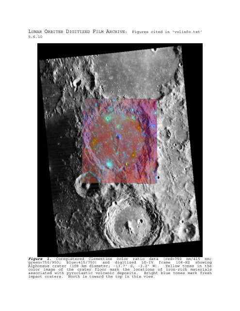
LUNAR ORBITER DIGITIZED FILM ARCHIVE: Figures cited in ‘volinfo.txt’<br />
5.6.10<br />
Figure 1. Coregistered Clementine color ratio data (red=750 nm/415 nm;<br />
green=750/950; blue=415/750) and digitized LO-IV frame 108-H2 showing<br />
Alphonsus crater (108 km diameter; -13.7º S, -3.2º W). Yellow tones in the<br />
color image of the crater floor mark the locations of iron-rich materials<br />
associated with pyroclastic volcanic deposits. Bright blue tones mark fresh<br />
impact craters. North is toward the top in this view.
Figure 2. The so-called ‘Photo of the Century’ (LO-II 162-H3) showing an<br />
oblique view of the interior of Copernicus crater.
Figure 3. Digital <strong>Lunar</strong> <strong>Orbiter</strong> view (left, LO-IV-90H) of southern Mare<br />
Serenitatis and western Mare Tranquillitatis (centered at ~3º N, 27º E).<br />
(Right) Coregistered LO and Clementine color ratio data (red=750 nm/415 nm;<br />
green=750/950; blue=415/750). Each strip of LO data is a single frame<br />
comprised of 3 sub-frames. Crater Delambre at lower right is 52 km in<br />
diameter.
Figure 4. Digitized <strong>Lunar</strong> <strong>Orbiter</strong> frame LO-IV-080-H3. (Top) Blotchy ‘water<br />
marks’ (an artifact of on-board film processing) and vertical stripes are<br />
present. (Bottom) Stripes have been mitigated and water marks remain.
Figure 5. Scanned <strong>Lunar</strong> <strong>Orbiter</strong> film strips. Note the pre-exposed film information at top, including frame<br />
number, gray-level chart, resolving power lines, and fiducial (triangular features at film edges; yellow<br />
arrows) and reseau (tiny white crosses or ‘+’ marks) marks (red arrows).
Figure 6. Film handling examples: (Top Left) Film strip is fed off canister reel and cut to a specified<br />
length. (Top Right) Four individual film strips are mounted on a scanning template, which has guides for<br />
consistent and accurate film placement. (Bottom Left) Anti-static brush is used to remove lint, dust, etc.<br />
(Bottom Right) The mounted template is placed on the CreoScitex Eversmart Pro II scanner. Scanning one<br />
template with four strips at 25 microns takes about 15 minutes of scan time.
Figure 7. Examples of different scanning resolutions for <strong>Lunar</strong> <strong>Orbiter</strong> film scans. (a) 25-micron scan of<br />
portion of LO film strip (XX-XXX) showing crater and hills. (b) 50-micron scan of same film strip. (c)<br />
“Difference Image” and (d) Absolute value image showing differences between 25- and 50-micron scans. Note<br />
that the details of the original image are preserved at 50 microns, and the differences consist mostly of<br />
film texture and blemishes. White dashes at film margins are ‘syncrhonization lines’ and white crosses are<br />
reseau marks.
Figure 8. Examples of destriping algorithms applied to scanned <strong>Lunar</strong> <strong>Orbiter</strong> film. Portions of LO frames<br />
XX-XXX? The spots on the images in the top row are water-mark blemishes.
Figure 9. Examples of film gaps. An enlargement of the boxed area at upper right is shown at lower left.<br />
LO Frame XX-XXX.
Figure 10. Digital mosaic of LO-IV 109H3. Destriped version of LO-IV 109H3.
Figure 11. Reprojected LO-IV HR frames 091 (left) and 103 (right; Sinusoidal Equal Area projection).<br />
Inset at left is a plot showing footprints of LO-IV HR frames 091 and 103. Note that each high-resolution<br />
frame has three sub-frames.
Figure 12. Mosaic of <strong>Lunar</strong> <strong>Orbiter</strong> frames showing the ‘Mare Serenitatis’ tile prior to destriping. Note<br />
watermarks and dark/bright stripes at frame boundaries.
Figure 13. Copernicus crater (93.0 km, 9.7N, 20.1W). (Left) Coregistered and map-projected LO IV (Frames<br />
126H2 & 121H2) and Clementine color ratio data (red=750/415; green=750/950; blue=415/750). (Right) Mosaic<br />
of LO-IV Frames 126H1/H2 and 121H1/H2 centered on Copernicus crater and surrounding region.
Figure 14. (Left) LO-V Frame 152M showing interior and portion of the rim of Copernicus crater. (Right)<br />
LO-V Frame 152H3 showing very high-resolution view of the floor of Copernicus crater. Note drapey texture<br />
of impact melts.