SSI Raw Experiment Data Record (REDR) for Phase 2 - USGS PDS ...
SSI Raw Experiment Data Record (REDR) for Phase 2 - USGS PDS ...
SSI Raw Experiment Data Record (REDR) for Phase 2 - USGS PDS ...

Create successful ePaper yourself
Turn your PDF publications into a flip-book with our unique Google optimized e-Paper software.
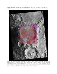
Original<br />
Project Galileo<br />
Software Interface Specification<br />
<strong>SSI</strong> <strong>Raw</strong> <strong>Experiment</strong> <strong>Data</strong> <strong>Record</strong><br />
(<strong>REDR</strong>) <strong>for</strong> <strong>Phase</strong> 2<br />
Mitchell White<br />
February 25,1998<br />
National Aeronautics and Space Administration<br />
Jet Propulsion Laboratory<br />
Cali<strong>for</strong>nia Institute of Technology<br />
Pasadena, Cali<strong>for</strong>nia<br />
D-11805<br />
Galileo Project Number 232-15
PROJECT GALILEO<br />
SOFTWARE INTERFACE SPECIFICATION<br />
COVER SHEET<br />
•<br />
NUMBER: D-11805<br />
VERSION 2.0<br />
DATE: FEBRUARY 25, 1998<br />
SIS NAME:<br />
<strong>SSI</strong> <strong>Raw</strong> <strong>Experiment</strong> <strong>Data</strong> <strong>Record</strong> (<strong>REDR</strong>) <strong>for</strong> <strong>Phase</strong> 2<br />
DOMAIN:<br />
System Subsystem Program Make/Use<br />
MIPS Realtime ADESPIKE, BADLABELS, , Make<br />
CATCD, CATLABEL, CDGEN,<br />
GALSOS, GEDRLIST, GLLBLEMCOR,<br />
GLLFILLIN, GLLMVLN, GLLTELEMPROC,<br />
<strong>SSI</strong>MERGE2, UNMOSAIC<br />
PURPOSE OF INTERFACE (SUMMARY):<br />
This interface describes the <strong>for</strong>mat and delivery specifications of the <strong>SSI</strong> <strong>REDR</strong>.<br />
INTERFACE MEDIUM:<br />
Disk File<br />
CD-ROM<br />
SIS COORDINATOR:<br />
H. Mortensen
SIGNATURES<br />
A PPROVAL<br />
W. Sible<br />
GLL Ground S/W System Engineer<br />
M. Belton S. LaVoie<br />
<strong>SSI</strong> Team Leader<br />
GLL IPS System Engineer<br />
K. Klaasen J. Johnson<br />
<strong>SSI</strong> Science Coordinator<br />
GLL SDT Chief<br />
G. Yagi L. Preheim<br />
MIPS Software Engineer<br />
MIPS Telemetry CDE<br />
C ONCURRENCE<br />
R. Bambery T. Handley<br />
MIPS Operations Supervisor<br />
MIPS System Engineer
Distribution<br />
D. Alexander 168-514<br />
R. Bambery 168-427<br />
S.Braun 264-829<br />
A. Culver 168-514<br />
R. Davis 264-211<br />
D. Jensen 168-514<br />
J. Johnson 264-744<br />
E. Kay-Im 168-414<br />
K. Klaasen 306-438<br />
D. Knight 168-414<br />
S. LaVoie 168-527<br />
H. Mortensen 168-514<br />
S. Noland 168-427<br />
Tina Pauro 168-514<br />
W. Sible 264-419<br />
C. Stanley 168-514<br />
G. Stufflebeam 264-419<br />
T. Thaller 168-514<br />
T. Trong 168-414<br />
Robin Vaughan 301-125L<br />
Vellum Files (2) 111-B25<br />
M. White 168-427<br />
P. Woncik 168-514<br />
G. Yagi 168-427<br />
J. Yoshimizu 168-514
Solid State Imaging <strong>Raw</strong> <strong>Experiment</strong> <strong>Data</strong> <strong>Record</strong> Software Interface Specification<br />
i<br />
TABLE OF CONTENTS<br />
Document Change Log.......................................................................iii<br />
TBD Items .......................................................................................iii<br />
Acronyms and Abbreviations............................................................iv<br />
1 INTRODUCTION<br />
1.1 Content Overview...........................................................1-1<br />
1.2 Scope..............................................................................1-1<br />
1.3 Applicable Documents....................................................1-1<br />
1.4 Subsystem Siting.............................................................1-1<br />
1.4.1 Interface Location, Medium.............................................1-1<br />
1.4.2 <strong>Data</strong> Source, Destinations, and Transfer Method..............1-1<br />
1.4.3 Generation Method and Frequency...................................1-2<br />
1.4.4 Pertinent Relationships with Other Interfaces................1-2<br />
1.4.5 Labeling and Identification (Internal/External)..............1-2<br />
1.5 Assumptions and Constraints...........................................1-2<br />
2 INTERFACE CHARACTERISTICS<br />
2.1 Hardware Characteristics and Limitations.....................2-1<br />
2.1.1 Special Equipment and Device Interfaces.........................2-1<br />
2.1.2 Special Setup Requirements............................................2-1<br />
2.2 Volume and Size.............................................................2-1<br />
2.3 Interface Medium Characteristics...................................2-1<br />
2.4 Failure Protection, Detection, and Recovery Features.......2-2<br />
2.4.1 File Backup Requirements...............................................2-2<br />
2.4.2 Security/Integrity Measures............................................2-2<br />
3 ACCESS<br />
3.1 Programs Affecting the Interface <strong>Data</strong>............................3-1<br />
3.2 Synchronization Considerations......................................3-2<br />
3.3 Input/Output Protocols, Calling Sequences.......................3-2<br />
3.4 Utility Programs............................................................3-2<br />
4 DETAILED INTERFACE SPECIFICATIONS<br />
4.1 Structure and Organization Overview.............................4-1<br />
4.2 Substructure Definition and Format.................................4-2<br />
4.2.1 Label Description...........................................................4-2<br />
4.2.2 Telemetry Header Description........................................4-2<br />
4.2.3 Bad-<strong>Data</strong> Value Header <strong>Record</strong>s..................................4-10<br />
4.2.4 Body Description..........................................................4-11<br />
4.2.5 Vicar label...................................................................4-14
Solid State Imaging <strong>Raw</strong> <strong>Experiment</strong> <strong>Data</strong> <strong>Record</strong> Software Interface Specification<br />
ii<br />
4.2.6 <strong>Phase</strong> 2 Telemetry Formats...............................................4-21<br />
APPENDIX A<br />
CAMERA PARAMETERS<br />
A.1 Camera Parameters.......................................................A-1<br />
APPENDIX B<br />
PICTURE NUMBER<br />
B.1 Picture Number..............................................................B-1<br />
APPENDIX C<br />
PROFILE ACTIVITY<br />
C.1 Profile Activity.............................................................C-1<br />
APPENDIX D<br />
MIPS PHYSICAL RECORDING WORDS<br />
D.1 MIPS Physical <strong>Record</strong>ing Words....................................D-1<br />
APPENDIX E<br />
BAD-DATA VALUE HEADER<br />
E.1 Bad-<strong>Data</strong> Value Header................................................E-1<br />
APPENDIX F<br />
PHASE ONE STRUCTURE<br />
F.1 Structure and Organization.............................................F-1<br />
APPENDIX G<br />
<strong>SSI</strong> GROUND CALIBRATION LABEL<br />
G.1 <strong>SSI</strong> Ground Calibration Label.........................................G-1<br />
LIST OF TABLES<br />
3-1 Programs Affecting <strong>SSI</strong> <strong>Data</strong>...........................................3-1<br />
4-1 Telemetry Header..........................................................4-3<br />
4-2 Image Line <strong>Record</strong>.........................................................4-11<br />
4-3 Vicar Label..................................................................4-14<br />
4-4 <strong>Phase</strong> Two Telemetry Format IDs...................................4-21<br />
A-1 <strong>SSI</strong> Filters.....................................................................A-1<br />
A-2 <strong>SSI</strong> Exposure Intervals in Milliseconds............................A-1<br />
A-3 CCD Fine Temperature Translations...............................A-2<br />
A-4 CCD Course Temperature Translations............................A-6<br />
D-1 MIPS Physical <strong>Record</strong>ing Words....................................D-1<br />
F-1 <strong>Phase</strong> One Telemetry Header..........................................F-1
Solid State Imaging <strong>Raw</strong> <strong>Experiment</strong> <strong>Data</strong> <strong>Record</strong> Software Interface Specification<br />
iii<br />
LIST OF TABLES - CON’T<br />
F-2 <strong>Phase</strong> One Image Line <strong>Record</strong>..........................................F-8<br />
F-4 <strong>Phase</strong> One Telemetry Format IDs..................................F-12<br />
Document Change Log<br />
Change Order Date Affected Portions<br />
Original October 30, 1991 All<br />
Version 2.0 September 10, 1997 All - Updated <strong>for</strong> GLL<br />
<strong>Phase</strong> II, including <strong>Phase</strong> I<br />
structure<br />
TBD Items<br />
Page Closure Date Item Description<br />
None
Solid State Imaging <strong>Raw</strong> <strong>Experiment</strong> <strong>Data</strong> <strong>Record</strong> Software Interface Specification<br />
iv<br />
ACRONYMS AND ABBREVIATIONS<br />
ANSI.....................American National Standards Institute<br />
APB.......................Asynchronous Playback<br />
ASCII....................American Standard Code <strong>for</strong> In<strong>for</strong>mation Interchange<br />
BARC....................Block Adaptive Rate Controlled Compression<br />
BPI........................Bits per inch<br />
CD-ROM...............Compact Disc Read-Only Memory<br />
CDWO..................Compact Disk Write Once media<br />
COW.....................Cut Out Window (same as ROI)<br />
CPU.......................Central Processing Unit<br />
DN........................<strong>Data</strong> Number<br />
DSN ID.................Deep Space Network Identification Number<br />
EDR.......................<strong>Experiment</strong> <strong>Data</strong> <strong>Record</strong><br />
EOF.......................End of File<br />
ERT.......................Earth Receive Time<br />
GCF.......................Ground Control Facility<br />
GLL.......................Galileo Project<br />
GMT......................Greenwich Mean Time<br />
HIIPS....................Home Institute Image Processing System<br />
ICT .......................Integer Cosine Trans<strong>for</strong>m<br />
IDR.......................Intermediate <strong>Data</strong> <strong>Record</strong><br />
I/F.........................Radiance/Solar Flux<br />
ISS........................VGR Imaging Science Subsystem<br />
ICT........................Integer Cosine Trans<strong>for</strong>m<br />
JOI.........................Jupiter Orbital Insertion<br />
JPL.........................Jet Propulsion Laboratory<br />
LRS.......................Low Rate Science<br />
LSB.......................Least Significant Bit<br />
MIPL.....................Multimission Image Processing Laboratory<br />
MIPS.....................Multimission Image Processing Subsystem<br />
MOS......................Mission Operations Subsystem<br />
MSEC....................Millisecond<br />
N/A......................Not Applicable<br />
OCM .....................On-Chip Mosaic<br />
OPNAV.................Optical Navigation<br />
<strong>PDS</strong>.......................Planetary <strong>Data</strong> Subsystem<br />
PTM.......................Proof Test Model (of <strong>SSI</strong>)<br />
<strong>REDR</strong>....................<strong>Raw</strong> <strong>Experiment</strong> <strong>Data</strong> <strong>Record</strong><br />
RCT.......................<strong>Record</strong> Creation Time<br />
R/S........................Reed/Solomon<br />
ROI .......................Region of Interest (same as COW)<br />
S/C........................Spacecraft<br />
SCLK.....................Spacecraft Clock<br />
SDR.......................System <strong>Data</strong> <strong>Record</strong><br />
SFDU....................Standard Formatted <strong>Data</strong> Unit<br />
SIS........................Software Interface Specification<br />
SNR......................Signal-to-Noise Ratio
Solid State Imaging <strong>Raw</strong> <strong>Experiment</strong> <strong>Data</strong> <strong>Record</strong> Software Interface Specification<br />
v<br />
ACRONYMS AND ABBREVIATIONS (CON'T)<br />
SPICE................................Spacecraft, Planetary, Instrument, C-matrix & Event<br />
Kernels<br />
<strong>SSI</strong>....................................GLL Solid State Imaging Subsytem<br />
STS....................................Sensor Test Set<br />
TBD...................................To Be Determined<br />
TDS...................................Telemetry Delivery Subsystem<br />
TIS....................................Telemetry Input Subsystem<br />
UDR..................................Unprocessed <strong>Data</strong> <strong>Record</strong><br />
UTC...................................Universal Time, Coordinated (same as GMT)<br />
VICAR..............................Video Image Communication and Retrieval<br />
WBDL...............................Wide Band <strong>Data</strong> Link
Solid State Imaging <strong>Raw</strong> <strong>Experiment</strong> <strong>Data</strong> <strong>Record</strong> Software Interface Specification<br />
1–1<br />
D-232-15<br />
<strong>SSI</strong> <strong>Raw</strong> <strong>Experiment</strong> <strong>Data</strong> <strong>Record</strong><br />
1 INTRODUCTION<br />
1.1 Content Overview<br />
This Software Interface Specification describes the content, <strong>for</strong>mat, and<br />
method of transfer of the Solid State Imaging Subsystem (<strong>SSI</strong>) <strong>Raw</strong> <strong>Experiment</strong><br />
<strong>Data</strong> <strong>Record</strong>s (<strong>REDR</strong>s) supplied by the Multimission Image Processing<br />
Subsystem (MIPS) to the Galileo <strong>SSI</strong> team and the Planetary <strong>Data</strong> System<br />
(<strong>PDS</strong>).<br />
1.2 Scope<br />
This specification is applicable to all <strong>SSI</strong> <strong>REDR</strong>s generated during the Orbital<br />
Operations phase of the mission.<br />
1.3 Applicable Documents<br />
[1] MIPS <strong>Phase</strong> 2 Software Requirements <strong>for</strong> <strong>SSI</strong>, IOM Gary Yagi: March 2,<br />
1994<br />
[2] Project Galileo Software Interface Specification; <strong>SSI</strong> CD-ROM, D-232-16<br />
[3] Project Galileo Software Interface Specification, <strong>SSI</strong> Image Catalog<br />
(Jupiter) <strong>Phase</strong> 2 D-3379<br />
[4] UNIX Porting Guide, D-9395, June 29, 1992, Bob Deen<br />
1.4 Subsystem Siting<br />
1.4.1 Interface Location, Medium<br />
The <strong>REDR</strong> interface medium shall be digital, with the distribution of <strong>REDR</strong><br />
files available electronically and on CD-ROM discs. Other media sources may<br />
be available with prior approval.<br />
1.4.2 <strong>Data</strong> Source, Destinations, and Transfer Method<br />
The <strong>SSI</strong> <strong>REDR</strong> shall be generated by MIPS procedures specifically developed or<br />
adapted <strong>for</strong> Galileo. The input to the <strong>REDR</strong> generation and validation
Solid State Imaging <strong>Raw</strong> <strong>Experiment</strong> <strong>Data</strong> <strong>Record</strong> Software Interface Specification<br />
1-2<br />
procedures shall be the Unprocessed <strong>Data</strong> <strong>Record</strong> (UDR) disk file generated by<br />
the MIPS Galileo realtime subsystem or the program UNMOSAIC which<br />
generates UDRs from On-Chip Mosaic UDRs or GLLMVLN which shifts bottom<br />
partial records and CCD line drop outs to their correct locations. The <strong>REDR</strong><br />
will reside at MIPS and shall be available to appropriate project personnel.<br />
1.4.3 Generation Method and Frequency<br />
The <strong>REDR</strong> shall be generated on the MIPS computer system. During Jupiter<br />
orbital operations, the <strong>REDR</strong>s shall be completed by end of mission.<br />
1.4.4 Pertinent Relationships with Other Interfaces<br />
The <strong>REDR</strong> <strong>for</strong>mat is identical to that of the Unprocessed <strong>Data</strong> <strong>Record</strong> (UDR)<br />
except the <strong>REDR</strong> may have a bad data value header and more binary header<br />
values and VICAR label field values determined. Also, the data <strong>for</strong>mat in the<br />
<strong>REDR</strong> is byte.<br />
The <strong>REDR</strong> header and line record <strong>for</strong>mats are similar to those used by the MIPS<br />
EDR interface to the Voyager Imaging Science Subsystem (ISS); they differ in<br />
Voyager and Galileo specific fields.<br />
1.4.5 Labeling and Identification (Internal/External)<br />
The internal file labeling shall be as defined in section 4.2. The external<br />
labeling will con<strong>for</strong>m to the file naming conventions found in reference [1].<br />
1.5 Assumptions and Constraints<br />
By design, the <strong>REDR</strong> files will not be radiometrically corrected.
Solid State Imaging <strong>Raw</strong> <strong>Experiment</strong> <strong>Data</strong> <strong>Record</strong> Software Interface Specification<br />
2–1<br />
2 INTERFACE CHARACTERISTICS<br />
2.1 Hardware Characteristics and Limitations<br />
N/A<br />
2.1.1 Special Equipment and Device Interfaces<br />
N/A<br />
2.1.2 Special Setup Requirements<br />
A premastered Write Once Compact disk (CDWO) will be generated and sent to<br />
a vendor <strong>for</strong> <strong>REDR</strong> CD-ROM disc mass production.<br />
Blemish correction is optionally available <strong>for</strong> the <strong>REDR</strong>. If blemish correction<br />
is desired, access to the <strong>SSI</strong> blemish calibration files is necessary.<br />
2.2 Volume and Size<br />
Each <strong>REDR</strong> file contains a telemetry header record followed by zero or more<br />
bad-data value header records (Appendix E), followed by 800 line records, each<br />
containing one line of image data.<br />
The length of the <strong>REDR</strong> line record is independent of the telemetry mode -- all<br />
have 1000 bytes. Each line record contains 200 bytes of binary data and 800<br />
bytes of pixel data.<br />
For summation mode (telemetry modes HIS and AI8), the line record is still<br />
1000 bytes . Only the first 400 samples and the first 400 lines of the pixel area<br />
are used to store valid image data.<br />
For other modes, see Table 4-4 <strong>for</strong> the expected number of lines and samples of<br />
the data.<br />
2.3 Interface Medium Characteristics<br />
The <strong>REDR</strong> pixel data and binary headers shall be written in VAX compatible<br />
(least significant byte first) <strong>for</strong>mat. For users running on hosts other than a<br />
VAX, all VICAR programs are capable of converting the pixel data into the<br />
current host’s <strong>for</strong>mat automatically. The binary headers are also converted as<br />
needed by the MIPS VICAR programs. Any local VICAR programs must check<br />
the header <strong>for</strong>mat and convert the data <strong>for</strong>mat as necessary. In<strong>for</strong>mation about
Solid State Imaging <strong>Raw</strong> <strong>Experiment</strong> <strong>Data</strong> <strong>Record</strong> Software Interface Specification<br />
2-2<br />
host <strong>for</strong>mats and converting between different <strong>for</strong>mats can be found in the<br />
VICAR Porting Guide [4].<br />
The distributed interface medium will be CD-ROM, accessible from standard<br />
Unix, VAX/VMS and VICAR commands. <strong>REDR</strong> header and data records will<br />
be organized as 8-bit bytes. The bits in each byte will be numbered from 0 to 7,<br />
with bit 0 being the least significant bit. All 2 and 4 byte integers have their<br />
least significant bit in the first byte.<br />
The image histogram, which trails the <strong>REDR</strong> telemetry header, will be<br />
organized as 32-bit words.<br />
A detached <strong>PDS</strong> label file will accompany each <strong>REDR</strong> file on the CD-ROM.<br />
The <strong>for</strong>mat of this <strong>PDS</strong> label is found in reference [2].<br />
2.4 Failure Protection, Detection, and Recovery Features<br />
2.4.1 File Backup Requirements<br />
The backup to the primary medium shall be disk <strong>REDR</strong> files residing on the<br />
MIPS system. Additional copies of the CDROM may be redistributed if<br />
required.<br />
2.4.2 Security/Integrity Measures<br />
N/A
Solid State Imaging <strong>Raw</strong> <strong>Experiment</strong> <strong>Data</strong> <strong>Record</strong> Software Interface Specification<br />
3–1<br />
3 ACCESS<br />
3.1 Programs Affecting the <strong>SSI</strong> <strong>Data</strong><br />
Table 3-1 lists programs pertaining to <strong>SSI</strong> data in the <strong>for</strong>m of the Unprocessed<br />
<strong>Data</strong> <strong>Record</strong>s (UDR), <strong>Raw</strong> <strong>Experiment</strong> <strong>Data</strong> <strong>Record</strong>s (<strong>REDR</strong>), and <strong>Experiment</strong><br />
<strong>Data</strong> <strong>Record</strong>s (EDR).<br />
Table 3-1. Programs Affecting <strong>SSI</strong> <strong>Data</strong><br />
Program Input Output Description<br />
ADESPIKE<br />
UDR<br />
<strong>REDR</strong><br />
Removes single-pixel spikes.<br />
<strong>REDR</strong><br />
<strong>REDR</strong><br />
EDR<br />
EDR<br />
BADLABELS UDR <strong>REDR</strong> Adds bad-data value headers<br />
and computer image entropy.<br />
CATCD <strong>REDR</strong> Adds a catalog record to the<br />
<strong>SSI</strong><strong>REDR</strong> table describing the<br />
CD-ROM location of the <strong>REDR</strong>.<br />
CATLABEL<br />
UDR<br />
<strong>REDR</strong><br />
UDR<br />
<strong>REDR</strong><br />
Updates VICAR label with<br />
in<strong>for</strong>mation from <strong>SSI</strong> catalog and<br />
the SPICE kernels.<br />
CDGEN<br />
<strong>REDR</strong><br />
EDR<br />
<strong>REDR</strong><br />
EDR<br />
Creates the <strong>PDS</strong> label file and<br />
index file to be included on the<br />
CD-ROMs.<br />
GALSOS<br />
UDR,<br />
<strong>REDR</strong><br />
EDR<br />
Radiometrically corrects;<br />
removes blemishes and per<strong>for</strong>ms<br />
a unit conversion of the pixel<br />
data.<br />
GEDRLIST UDR Print binary labels and bad-data<br />
value headers.<br />
GLLBLEMCOR <strong>REDR</strong> <strong>REDR</strong> Removes camera blemishes.
Solid State Imaging <strong>Raw</strong> <strong>Experiment</strong> <strong>Data</strong> <strong>Record</strong> Software Interface Specification<br />
3-2<br />
Table 3-1. Programs Affecting <strong>SSI</strong> <strong>Data</strong> - Continued<br />
Program Input Output Description<br />
GLLFILLIN<br />
UDR<br />
<strong>REDR</strong><br />
<strong>REDR</strong><br />
<strong>REDR</strong><br />
Fills in missing image lines due to<br />
data outage or data compression<br />
errors.<br />
EDR<br />
EDR<br />
GLLMVLN UDR UDR Shifts lines downward due to the<br />
CDS line dropout problem and<br />
bottom partial records.<br />
GLLTELEMPROC<br />
telemetry<br />
data<br />
UDR<br />
Generates UDR files.<br />
<strong>SSI</strong>MERGE2 UDR UDR Merges two or more images to<br />
produce another image with less<br />
missing data.<br />
UNMOSAIC UDR UDR Accepts an on-chip mosaicked<br />
(OCM) UDR as input and outputs<br />
each mosaic element as a<br />
separate UDR.<br />
3.2 Synchronization Considerations<br />
N/A<br />
3.3 Input/Output Protocols, Calling Sequences<br />
N/A<br />
3.4 Utility Programs<br />
GEDRLIST displays binary header and prefix labels <strong>for</strong> verification purposes.<br />
LABEL-LIST displays VICAR label in<strong>for</strong>mation <strong>for</strong> verification purposes.<br />
LABLIST displays VICAR label in<strong>for</strong>mation in a compact <strong>for</strong>mat <strong>for</strong><br />
verification purposes.
Solid State Imaging <strong>Raw</strong> <strong>Experiment</strong> <strong>Data</strong> <strong>Record</strong> Software Interface Specification<br />
4–1<br />
4 DETAILED INTERFACE SPECIFICATIONS<br />
4.1 Structure and Organization Overview<br />
Each <strong>REDR</strong> file will begin with a VICAR label, followed by the <strong>REDR</strong><br />
telemetry header and a number of <strong>REDR</strong> bad-data value headers followed by<br />
<strong>REDR</strong> line records. Each line record will contain 200 bytes of line header<br />
in<strong>for</strong>mation plus the pixel data (8 bits/pixel). See figure 4-1 <strong>for</strong> a diagram of<br />
the <strong>REDR</strong> file.<br />
VICAR Label<br />
Binary Header<br />
(Telemetry Header <strong>Record</strong> &<br />
Bad-<strong>Data</strong> Value Header <strong>Record</strong>s)<br />
Body<br />
Binary<br />
Prefix<br />
(Line Header)<br />
Image <strong>Data</strong><br />
(pixels)<br />
Figure 4-1. <strong>REDR</strong>/EDR File Diagram<br />
All records have a fixed 1000-byte length within each <strong>REDR</strong> file. All <strong>for</strong>mats<br />
have 1000-byte records. Note: Summation mode images occupy the first 400<br />
lines and 400 samples of the 800 line by 800 sample <strong>REDR</strong> and UDR.<br />
For all <strong>REDR</strong>s (including summation mode), the telemetry header is split into<br />
two physical records. The first 1000 bytes are placed in the first physical<br />
record after the VICAR label (the VICAR label may span more than one<br />
physical record), and the last 800 bytes are placed in the next physical record.<br />
The last 200 bytes of this record are zero filled.<br />
There will be a one-to-one correspondence between line records and image lines<br />
(Excluding the header records, line record n will contain the data <strong>for</strong> image line<br />
n). Missing data lines can be artificially filled by the GLLFILLIN program<br />
using interpolation. Missing ICT or Huffman compressed <strong>SSI</strong> packets will not be
Solid State Imaging <strong>Raw</strong> <strong>Experiment</strong> <strong>Data</strong> <strong>Record</strong> Software Interface Specification<br />
4-2<br />
interpolated over 8 line slices. The fill-in process will occur based on<br />
parameters given by the <strong>SSI</strong> Team. Certain fields of each line header<br />
containing data sequencing in<strong>for</strong>mation will be maintained even during data<br />
gaps.<br />
4.2 Substructure Definition and Format<br />
All fields of the telemetry and line headers are unsigned integers unless<br />
specified otherwise. All real numbers are represented in ASCII as noted <strong>for</strong><br />
each field. The record identifier, byte 0, of every physical record identifies<br />
the type of that record. Each 1800-byte telemetry header record is split into<br />
two 1000-byte records. The last 200 bytes of the second record contains filler.<br />
Bad-data value header records will not cross physical record boundaries.<br />
4.2.1 Label Description<br />
The VICAR label is an ASCII record intended <strong>for</strong> use by MIPS and VICAR<br />
programs; others may ignore this record. This label always appears at the<br />
beginning of an <strong>REDR</strong> file. Since the length of this label may exceed one<br />
physical record, non-VICAR programs should ignore all records with a "<strong>Record</strong><br />
ID", byte 0, of 32 or more. See section 4.2.5 <strong>for</strong> more details about the VICAR<br />
label.<br />
4.2.2 Telemetry Header Description<br />
The <strong>REDR</strong> telemetry header record contains ancillary in<strong>for</strong>mation specific to<br />
the image. It should not be confused with other binary header records, such as<br />
the bad-data value header records which are discussed later.<br />
The <strong>REDR</strong> telemetry header record is described in Table 4-1.
Solid State Imaging <strong>Raw</strong> <strong>Experiment</strong> <strong>Data</strong> <strong>Record</strong> Software Interface Specification<br />
4–3<br />
Table 4-1. Telemetry Header<br />
Byte Bit Item Description<br />
0 <strong>Record</strong> ID ALWAYS = 0 <strong>for</strong> this<br />
header.<br />
1 Reserved Used during <strong>Phase</strong> One.<br />
2 - 11 Project Project name, 10 ASCII<br />
characters = "GALILEO".<br />
12 - 17 Instrument Instrument name, 6 ASCII<br />
characters = "<strong>SSI</strong>".<br />
18 - 19 Reserved Used during <strong>Phase</strong> One.<br />
20 - 21 Log. Seq. Logical sequence, binary<br />
count reset to zero <strong>for</strong> the<br />
first record of a file<br />
(header record) and<br />
incremented by one <strong>for</strong><br />
each record in the file.<br />
Always = 0 <strong>for</strong> this record.<br />
Note<br />
For UDRs, <strong>REDR</strong>s, and<br />
summation-mode EDRs,<br />
the telemetry header<br />
record spans two<br />
physical records.<br />
First ERT Earth Received Time<br />
(UTC) of the first packet<br />
received <strong>for</strong> this image.<br />
22 - 23<br />
YEAR<br />
Year<br />
24 - 25<br />
DAY<br />
Day of year<br />
26<br />
HOUR<br />
Hour of day<br />
27<br />
MIN<br />
Minute of hour<br />
28<br />
SEC<br />
Second of minute<br />
29 - 30<br />
MSEC<br />
Millisecond of second<br />
Last ERT<br />
31 - 32<br />
33 - 34<br />
35<br />
36<br />
37<br />
38 - 39<br />
40 - 43<br />
44<br />
45<br />
46<br />
YEAR<br />
DAY<br />
HOUR<br />
MIN<br />
SEC<br />
MSEC<br />
First SCLK<br />
RIM<br />
MOD91<br />
MOD10<br />
MOD8<br />
Earth Received Time<br />
(UTC) of the last packet<br />
received <strong>for</strong> this image.<br />
Year<br />
Day of year<br />
Hour of day<br />
Minute of hour<br />
Second of minute<br />
Millisecond of second<br />
Spacecraft Clock of the<br />
first record in the file<br />
containing valid data.<br />
Valid For<br />
UDR <strong>REDR</strong> EDR<br />
• • •<br />
• • •<br />
• • •<br />
• • •<br />
• • •<br />
• • •<br />
• • •
Solid State Imaging <strong>Raw</strong> <strong>Experiment</strong> <strong>Data</strong> <strong>Record</strong> Software Interface Specification<br />
4-4<br />
Table 4-1. Telemetry Header - Continued<br />
Byte Bit Item Description<br />
47 - 50<br />
51<br />
52<br />
53<br />
54 - 55<br />
56 - 57<br />
58<br />
59<br />
60<br />
61 - 62<br />
Last SCLK<br />
RIM<br />
MOD91<br />
MOD10<br />
MOD8<br />
SCET<br />
YEAR<br />
DAY<br />
HOUR<br />
MIN<br />
SEC<br />
MSEC<br />
Spacecraft Clock of the<br />
last record in the file<br />
containing valid data.<br />
Spacecraft Event Time<br />
(UTC) at the middle of<br />
shutter-open period.<br />
Year<br />
Day of year<br />
Hour of day<br />
Minute of hour<br />
Second of minute<br />
Millisecond of minute<br />
63 - 121 MIPS PRD MIPS Physical <strong>Record</strong>ing<br />
<strong>Data</strong> of the first record of<br />
the file (ASCII). See<br />
Appendix D. Not used.<br />
122-123 Telemetry <strong>Record</strong><br />
Format ID<br />
From predtelemfmtid field<br />
of ssioverview table of the<br />
database. See Section 4.2.6<br />
<strong>for</strong> values.<br />
124 - 127 Reserved Used during <strong>Phase</strong> One.<br />
128 BOOM flag Boom obscuration flag.<br />
0: Boom present<br />
1: Boom may be present<br />
2: Boom not present<br />
Updated by BOOMFLAG<br />
and CATLABEL<br />
129 - 130 Missing Lines Number of expected line<br />
records in the file,<br />
excluding those lines not<br />
within the COW, with no<br />
valid pixels.<br />
131 - 132 Partial Lines Total number of expected<br />
line records in the file,<br />
excluding those lines not<br />
within the COW, which<br />
contain some valid pixels.<br />
133 - 134 Reserved Used during <strong>Phase</strong> One.<br />
135 - 136 Seq. Breaks Total number of packet<br />
gaps (indicated by a<br />
discontinuity in the packet<br />
sequence number).<br />
Valid For<br />
UDR <strong>REDR</strong> EDR<br />
• • •<br />
• • •<br />
• •<br />
• • •<br />
• • •<br />
• • •<br />
• • •<br />
• • •
Solid State Imaging <strong>Raw</strong> <strong>Experiment</strong> <strong>Data</strong> <strong>Record</strong> Software Interface Specification<br />
4–5<br />
Table 4-1. Telemetry Header - Continued<br />
Byte Bit Item Description<br />
137 - 142 Reserved Used during <strong>Phase</strong> One.<br />
143 - 144 SFDUs Total number of minor<br />
frames in this file which<br />
were derived from SFDU<br />
input. Also equal to the<br />
number of packets<br />
available <strong>for</strong> this file.<br />
145 - 151 Pic. No. Picture number. Seven-<br />
ASCII-character<br />
"XXYZZZZ" (See Appendix<br />
C).<br />
152 - 163 Reserved Used during <strong>Phase</strong> One.<br />
164 - 165<br />
0<br />
1<br />
2<br />
3<br />
4<br />
5<br />
6<br />
7<br />
Flags<br />
Compression<br />
Comp Mode<br />
Extended<br />
Exposure<br />
Flood<br />
Blemish<br />
Clock<br />
ICT Compression<br />
Huffman<br />
Compression<br />
Reserved<br />
BARC Compression<br />
0=off<br />
1=on<br />
BARC Compression Mode<br />
(Valid only if compression<br />
flag is set)<br />
0= rate control<br />
1= info preserv<br />
Exposure Mode<br />
0= normal<br />
1= extended<br />
Light Flood Status<br />
0= off<br />
1= on<br />
Blemish Protection<br />
0= off<br />
1= on<br />
Parallel Clock State<br />
0= normal<br />
1= inverted<br />
0=off<br />
1=on<br />
0=off<br />
1=on<br />
8- 15<br />
166 - 171 Mean DN Mean DN level of all<br />
valid pixels in the<br />
expected image, excluding<br />
data not in the COW.<br />
Real number represented as<br />
ASCII string in the <strong>for</strong>m<br />
"123.12".<br />
Valid For<br />
UDR <strong>REDR</strong> EDR<br />
• • •<br />
• • •<br />
• • •<br />
• • •
Solid State Imaging <strong>Raw</strong> <strong>Experiment</strong> <strong>Data</strong> <strong>Record</strong> Software Interface Specification<br />
4-6<br />
Table 4-1. Telemetry Header - Continued<br />
Byte Bit Item Description<br />
172 - 177 Truncated bits Mean number of truncated<br />
bits per pixel, excluding<br />
data not in the COW.<br />
Real number represented as<br />
ASCII string in the <strong>for</strong>m<br />
"12.345" (<strong>for</strong> BARC<br />
compression only).<br />
178 - 183 Truncated pixel Mean number of truncated<br />
pixels per line. Real<br />
number represented as<br />
ASCII string in the <strong>for</strong>m<br />
"123.12"<br />
(<strong>for</strong> BARC compression<br />
only).<br />
184 - 195 I/F Mean I over F level. Real<br />
number represented as<br />
ASCII string in the <strong>for</strong>m<br />
"123.12". Added by<br />
GALSOS.<br />
196 - 202 Entropy Average Entropy level <strong>for</strong> the<br />
whole picture (bits per<br />
pixel). Real number<br />
represented as ASCII<br />
string in the <strong>for</strong>m<br />
"12.1234". Added by<br />
GALSOS or BADLABELS.<br />
203 - 307 Entropies Entropy level <strong>for</strong> 15 lines.<br />
First line is 50, and<br />
incremented by 50 to line<br />
750. 15 real numbers<br />
represented as ASCII<br />
strings in the <strong>for</strong>m<br />
"12.1234" and null<br />
ternimated. Added by<br />
GALSOS or BADLABELS.<br />
308 - 331 Pointing<br />
Scan plat<strong>for</strong>m direction<br />
coordinates at middle of<br />
<strong>Phase</strong> 1 Only shutter-open period in<br />
J2000. Three real numbers<br />
<strong>for</strong> right ascension,<br />
declina-tion and twist<br />
angles represented as<br />
ASCII strings in the <strong>for</strong>m<br />
"1234.123".<br />
Valid For<br />
UDR <strong>REDR</strong> EDR<br />
• • •<br />
• • •<br />
•<br />
• •<br />
• •
Solid State Imaging <strong>Raw</strong> <strong>Experiment</strong> <strong>Data</strong> <strong>Record</strong> Software Interface Specification<br />
4–7<br />
Table 4-1. Telemetry Header - Continued<br />
Byte Bit Item Description<br />
332 - 347 Scale Factors Radiometric calibration<br />
scale factors. Two real<br />
numbers in the <strong>for</strong>m<br />
"123.1234". First number is<br />
reflectance/DN, the<br />
second is the radiance/DN<br />
scale factor. Added by<br />
GALSOS.<br />
348 - 379 Slope-File Radiometric file used <strong>for</strong><br />
systematic processing. 32<br />
ASCII characters. Added<br />
by GALSOS.<br />
380 - 411 Offset-File Radiometric file (dark<br />
current) used <strong>for</strong> systematic<br />
processing. 32 ASCII<br />
characters. Added by<br />
GALSOS.<br />
412 - 431 Activity 20 ASCII characters of the<br />
<strong>for</strong>m:<br />
"NNTIOOOOOOMM#SSSXXXX<br />
(See Appendix C).<br />
432 Filler<br />
433 Filter Filter position (See<br />
Appendix A).<br />
434 Exposure Exposure number (See<br />
Appendix A).<br />
435 Imaging Mode or<br />
Instrument Frame<br />
Rate<br />
0: 60-2/3 seconds (Low)<br />
1: 8-2/3 secs (High)<br />
2: 30-1/3 secs (Medium)<br />
3: 2-1/3 secs (Radiation)<br />
4: 15-1/6 secs (Summation)<br />
436 Camera gain state 0: Gain 1 = 400K<br />
1: Gain 2 = 100K<br />
2: Gain 3 = 40 K<br />
3: Gain 4 = 10 K<br />
437- 440 Range Target's range to sun in<br />
kilometers. Updated by<br />
CATLABEL.<br />
441 Reserved Used during <strong>Phase</strong> One.<br />
442 - 443 Version MIPS catalog version<br />
number, reserved <strong>for</strong> MIPS<br />
use. Not used<br />
Valid For<br />
UDR <strong>REDR</strong> EDR<br />
• • •<br />
• • •<br />
• • •<br />
• • •<br />
• • •<br />
• •<br />
• • •<br />
•<br />
•<br />
•
Solid State Imaging <strong>Raw</strong> <strong>Experiment</strong> <strong>Data</strong> <strong>Record</strong> Software Interface Specification<br />
4-8<br />
Table 4-1. Telemetry Header - Continued<br />
Byte Bit Item Description<br />
444 - 447<br />
448<br />
449<br />
450<br />
451 - 454<br />
455<br />
456<br />
457<br />
458-465<br />
466-473<br />
474-481<br />
482-489<br />
490<br />
491<br />
492<br />
493 0-4<br />
5-6<br />
7<br />
Starting SCLK<br />
RIM<br />
MOD91<br />
MOD10<br />
MOD8<br />
Ending SCLK<br />
RIM<br />
MOD91<br />
MOD10<br />
MOD8<br />
<strong>SSI</strong>3_PKT when<br />
available.<br />
Plat<strong>for</strong>m RA<br />
Plat<strong>for</strong>m DEC<br />
Plat<strong>for</strong>m TWIST<br />
Plat<strong>for</strong>m CLOCK<br />
angle<br />
Standard<br />
Housekeeping<br />
<strong>Data</strong> Words 14, 19,<br />
and 22 <strong>for</strong> this<br />
image when<br />
available.<br />
Standard<br />
Housekeeping<br />
<strong>Data</strong> Word 23 <strong>for</strong><br />
this image when<br />
available.<br />
Spacecraft Clock of the<br />
start of image. This clock<br />
refers to the start of the<br />
<strong>SSI</strong> frame cycle.<br />
Spacecraft Clock at the<br />
end of image. This clock<br />
refers to the end of the <strong>SSI</strong><br />
frame cycle.<br />
<strong>Data</strong> portion <strong>for</strong> <strong>SSI</strong>3<br />
telemetry packet<br />
containing AACS. Values<br />
will be represented as<br />
ASCII strings in the <strong>for</strong>m<br />
1234.12 and null<br />
terminated. RA and DEC<br />
are in the EME50<br />
coordinate system<br />
CCD Fine Temperature and<br />
CCD Coarse Temperature<br />
Values from 0 to 255.<br />
See Appendix A <strong>for</strong><br />
temperature translation<br />
tables.<br />
Picture Count<br />
Increments every nonzero<br />
exposure and dark<br />
current calibration<br />
Exposure Number<br />
(See Appendix A)<br />
Commanded Gain<br />
0=Gain 1 = 400 K<br />
1=Gain 2 = 100 K<br />
2=Gain 3 = 40 K<br />
3=Gain 4 = 10 K<br />
Light Flood<br />
0=on<br />
1=off<br />
Valid For<br />
UDR <strong>REDR</strong> EDR<br />
• • •<br />
• • •<br />
• • •<br />
• • •<br />
• • •
Solid State Imaging <strong>Raw</strong> <strong>Experiment</strong> <strong>Data</strong> <strong>Record</strong> Software Interface Specification<br />
4–9<br />
Table 4-1. Telemetry Header - Continued<br />
Byte Bit Item Description<br />
494 0-2<br />
3<br />
4<br />
5<br />
6<br />
495 0-1<br />
2-3<br />
4<br />
5-7<br />
Standard<br />
Housekeeping<br />
<strong>Data</strong> Word 24 <strong>for</strong><br />
this image when<br />
available.<br />
Standard<br />
Housekeeping<br />
<strong>Data</strong> Word 25 <strong>for</strong><br />
this image when<br />
available.<br />
Command Filter Pos.<br />
(See Appendix A)<br />
Commanded Filter step<br />
0=absolute<br />
1=step<br />
Commanded Blem. Mode<br />
0=off<br />
1=on<br />
Commanded Expos. Mode<br />
0=normal<br />
1=extended<br />
Commanded Expos Cycle<br />
0=cycle 1<br />
1=cycle 2<br />
Gain State used<br />
0=Gain 1=400 K<br />
1=Gain 2=100 K<br />
2=Gain 3=40 K<br />
3=Gain 4=10 K<br />
BARC Compressor Status<br />
(bit 2) and Compressor<br />
Mode (bit 3)<br />
0=out<br />
1=in & rate controlled<br />
2=out<br />
3=in & infopreserving<br />
Long Exposure Cycle<br />
0=cycle 1<br />
1=cycle 2<br />
Image Mode<br />
0=60-2/3s<br />
2=8-2/3s<br />
4=30-1/3s<br />
5=15-1/6s<br />
6=2-1/3s<br />
Valid For<br />
UDR <strong>REDR</strong> EDR<br />
• • •<br />
• • •
Solid State Imaging <strong>Raw</strong> <strong>Experiment</strong> <strong>Data</strong> <strong>Record</strong> Software Interface Specification<br />
4-10<br />
Table 4-1. Telemetry Header - Continued<br />
Byte Bit Item Description<br />
496 0<br />
1-3<br />
4<br />
5<br />
6<br />
7<br />
Standard<br />
Housekeeping<br />
<strong>Data</strong> Word 26 <strong>for</strong><br />
this image when<br />
available.<br />
Odd Parity<br />
Actual Filter Position 0-7<br />
(See Appendix A)<br />
Blemish Protection<br />
0=off<br />
1=on<br />
Watch Dog Timer<br />
0=not tripped<br />
1=tripped<br />
Parallel Clock<br />
0=normal<br />
1=inverted<br />
Memory Write Protect<br />
0=write protect off<br />
1=write protecton on<br />
497 - 775 Reserved<br />
776 -1799 Histogram 256 32-bit binary valued<br />
histogram of the pixels <strong>for</strong><br />
this file, including fill<br />
data.<br />
Valid For<br />
UDR <strong>REDR</strong> EDR<br />
• • •<br />
• • •<br />
NOTE<br />
Table 4-1 above defines the logical telemetry header<br />
structure. The physical structure is dependent upon the<br />
file structure, which is described in paragraph 4.1.<br />
4.2.3 Bad-<strong>Data</strong> Value Header <strong>Record</strong>s<br />
These records describe several types of bad data values. Each record describes<br />
only one type of bad data values (dropouts, saturated pixels, Low-full-well<br />
pixels, and single spiked pixels). Depending on the number of bad pixels, each<br />
Bad-<strong>Data</strong> Value header may generate several physical records. Each record is<br />
independent of the other records and is identified by the "<strong>Record</strong> Id" field<br />
which is located at byte 0. The definition of these records is provided in<br />
Appendix E.
Solid State Imaging <strong>Raw</strong> <strong>Experiment</strong> <strong>Data</strong> <strong>Record</strong> Software Interface Specification<br />
4–11<br />
4.2.4 Body Description<br />
The <strong>REDR</strong> body or image line record is described in the Table 4-2.<br />
Table 4-2. Image Line <strong>Record</strong><br />
Byte Bit Item Description<br />
Valid For<br />
UDR <strong>REDR</strong> EDR<br />
0 <strong>Record</strong> ID Always = 2 <strong>for</strong> line records. • • •<br />
1 - 3 Reserved Used during <strong>Phase</strong> One.<br />
4 - 5 Log. Seq. Logical sequence, binary • • •<br />
count reset to zero <strong>for</strong> the<br />
first record of a file<br />
(header record) and<br />
incremented by one <strong>for</strong><br />
each record in the file.<br />
6 - 7<br />
8 - 9<br />
10<br />
11<br />
12<br />
13 - 14<br />
ERT<br />
YEAR<br />
DAY<br />
HOUR<br />
MIN<br />
SEC<br />
MSEC<br />
Earth Received Time (in<br />
UTC) of the first telemetry<br />
packet with first pixel<br />
located in this line.<br />
Obtained from the ERT in<br />
the GCF block containing<br />
this field.<br />
Year<br />
Day of year<br />
Hour of day<br />
Minute of hour<br />
Second of minute<br />
Millisecond of second<br />
• • •<br />
15 - 18<br />
19<br />
20<br />
21<br />
SCLK<br />
RIM<br />
MOD91<br />
MOD10<br />
MOD8<br />
22 - 80 MIPS Physical<br />
<strong>Record</strong>ing Words<br />
Spacecraft clock readout of<br />
the 1st minor frame of this<br />
line.<br />
59 ASCII characters which<br />
define the recording and<br />
validation devices,<br />
software version and CPU<br />
used to write this record<br />
and the data on which it<br />
was recorded. A detailed<br />
explanation of this field is<br />
provided in Appendix D.<br />
Not used.<br />
• • •<br />
•
Solid State Imaging <strong>Raw</strong> <strong>Experiment</strong> <strong>Data</strong> <strong>Record</strong> Software Interface Specification<br />
4-12<br />
Table 4-2. Image Line <strong>Record</strong> - Continued<br />
Byte Bit Item Description<br />
81 - 82 Telemetry <strong>Record</strong><br />
Format ID<br />
Predict from ssioverview<br />
table of the database. See<br />
section 4.2.6 <strong>for</strong> values<br />
83 Input Type Decimal value:<br />
0: S/C Flight <strong>Data</strong> MOS<br />
1: PTM <strong>Data</strong><br />
2: Ext. Simulation<br />
3: S/C Flight <strong>Data</strong> Test<br />
4: Internal Simulation<br />
5-255: Not used<br />
84<br />
0<br />
1<br />
2<br />
3<br />
4<br />
5<br />
6<br />
7<br />
Input Source<br />
SFDU data<br />
WBDL<br />
SDR<br />
IDR<br />
EDR<br />
MIPS Realtime<br />
APB<br />
Not used<br />
Bit will be set to 1<br />
according to input data<br />
source.<br />
Valid For<br />
UDR <strong>REDR</strong> EDR<br />
• • •<br />
• • •<br />
• • •<br />
85 -102 Reserved Used during <strong>Phase</strong> One.<br />
103 - 106<br />
Truncation<br />
Number of truncated bits • • •<br />
0 - 1<br />
2 - 3<br />
4 - 5<br />
....<br />
24 - 25<br />
26 - 31<br />
BLOCK 0<br />
BLOCK 1<br />
BLOCK 2<br />
....<br />
BLOCK 12<br />
Filler<br />
per block due to data<br />
compression. 2 bits/block,<br />
13 blocks/line. Each block<br />
contains 64 pixels except<br />
last one which contain 32<br />
pixels (<strong>for</strong> BARC<br />
Compression only).<br />
107 - 108 Truncated Total number of pixels • • •<br />
truncated at end of line due<br />
to BARC data compression.<br />
109 - 110 Version Catalog version <strong>for</strong><br />
• •<br />
identical images. Not<br />
implemented<br />
111 - 112 Reserved Used during <strong>Phase</strong> One.<br />
113 DSN ID Deep Space Network • • •<br />
Station where packet was<br />
received. As defined in<br />
GLL-820-13/OPS-6-8.<br />
114 - 115 Line Number Image line number, 1-800. • • •<br />
116 Reserved Used during <strong>Phase</strong> One.
Solid State Imaging <strong>Raw</strong> <strong>Experiment</strong> <strong>Data</strong> <strong>Record</strong> Software Interface Specification<br />
4–13<br />
Table 4-2. Image Line <strong>Record</strong> - Continued<br />
Byte Bit Item Description<br />
117-118<br />
119-120<br />
121-122<br />
123-124<br />
125<br />
Segments<br />
ss1<br />
es1<br />
ss2<br />
es2<br />
Line Construction<br />
The starting and ending<br />
samples <strong>for</strong> up to two<br />
segments of an image line<br />
identifying where data<br />
exist . OPNAVs with 3<br />
segments will combine the<br />
first 2 segments together<br />
into ss1 and es1.<br />
Number of Telemetry<br />
packets used to create this<br />
image line.<br />
Full Packets<br />
Partial Packets<br />
0-3<br />
4-7<br />
126 APID Application packet ID.<br />
30 <strong>for</strong> ssi1 and 31 <strong>for</strong> ssi2.<br />
127 - 130 PKT_Sequence id TIS packet sequence id.<br />
Packet sequence ids are <strong>for</strong><br />
the purpose of maintaining<br />
proper order of packets. If<br />
more than one packet is<br />
used to reconstruct the line,<br />
only the packet id of the<br />
first telemetry packet is<br />
stored.<br />
131 - 132 PKT_Pixel_Start Starting sample location<br />
<strong>for</strong> the packet identified<br />
by the PKT_Sequence id.<br />
133 - 134<br />
135 - 136<br />
137 - 138<br />
139 - 140<br />
141<br />
142<br />
143<br />
144 - 145<br />
Truth Window<br />
Position<br />
Start Pixel<br />
Stop Pixel<br />
RCT<br />
YEAR<br />
DAY<br />
HOUR<br />
MIN<br />
SEC<br />
MSEC<br />
The position of the Truth<br />
Window. 0,0 indicates no<br />
truth window on this line<br />
The TIS <strong>Record</strong> Creation<br />
Time of packet.<br />
Year<br />
Day of year<br />
Hour of day<br />
Minute of hour<br />
Second of minute<br />
Millisecond of second<br />
Valid For<br />
UDR <strong>REDR</strong> EDR<br />
• • •<br />
• • •<br />
• • •<br />
• • •<br />
• • •<br />
• • •<br />
• • •
Solid State Imaging <strong>Raw</strong> <strong>Experiment</strong> <strong>Data</strong> <strong>Record</strong> Software Interface Specification<br />
4-14<br />
Table 4-2. Image Line <strong>Record</strong> - Continued<br />
Byte Bit Item Description<br />
146 Decompression<br />
Status/Errors<br />
Decompression<br />
status/errors.<br />
0: No errors detected<br />
-1: Incomplete data <strong>for</strong><br />
decompression<br />
147 - 152 Compression Ratio Compression ratio <strong>for</strong><br />
entire line. Real number<br />
represented as an ASCII<br />
string in the <strong>for</strong>m "123.12"<br />
153 - 199 Reserved.<br />
200 - 599<br />
600 - 999<br />
or<br />
Pixel <strong>Data</strong><br />
Filler<br />
or<br />
400 8-bit unsigned pixel<br />
values (summation mode<br />
only).<br />
Set to zero (summation<br />
mode only).<br />
or<br />
Valid For<br />
UDR <strong>REDR</strong> EDR<br />
• • •<br />
• • •<br />
•<br />
•<br />
200 - 999<br />
200 - 999<br />
Pixel <strong>Data</strong><br />
Pixel <strong>Data</strong><br />
800 8-bit unsigned pixel<br />
values.<br />
Summation Mode:<br />
•<br />
•<br />
•<br />
or<br />
or<br />
400 16-bit signed pixel<br />
values, radiometrically<br />
corrected<br />
200 - 1799<br />
Pixel <strong>Data</strong><br />
Full Frame Mode:<br />
•<br />
800 16-bit signed pixel<br />
values, radiometrically<br />
corrected<br />
4.2.5 VICAR Label<br />
The <strong>SSI</strong> VICAR image label is created as each new image is received by MIPS real time. This<br />
section describes the label keywords initially included on the labels when the UDRs and<br />
<strong>REDR</strong>s are created or when the label keywords are added to the labels by the radiometric<br />
correction program GALSOS.<br />
The <strong>SSI</strong> VICAR image label includes data which identify the mission, spacecraft, instrument,<br />
target, and frame, and various camera and image geometry data pertinent to the interpretation<br />
of the image. During systematic and science processing, individual programs may extract and<br />
use various image identifiers and camera parameters stored in the label. The image geometry
Solid State Imaging <strong>Raw</strong> <strong>Experiment</strong> <strong>Data</strong> <strong>Record</strong> Software Interface Specification<br />
4–15<br />
in<strong>for</strong>mation included in the label is normally ignored during processing, since more accurate<br />
in<strong>for</strong>mation is available from SPICE files.<br />
As each new version of an image is produced, the VICAR system will automatically copy the<br />
image label and add the program name, user name, and date to the processing history. In<br />
addition, individual programs may add processing in<strong>for</strong>mation to the label.<br />
The flight label is in free <strong>for</strong>mat, with each label item stored in the <strong>for</strong>m "keyword=value".<br />
Summation-mode frames can be identified by their 2-1/3 or 15-1/6 frame rate. The majority of<br />
the label items are generated by the Real-Time subsystem's Image-Builder program.<br />
Below is a listing of a sample <strong>SSI</strong> flight label of a <strong>Phase</strong> 2 <strong>REDR</strong> with a spacecraft clock value of 349632000 and<br />
ICT compressed. MIPS VICAR program LABEL was used to produce this <strong>for</strong>matted version of the VICAR label.<br />
************ File S0349632000.R ************<br />
3 dimensional IMAGE file<br />
File organization is BSQ<br />
Pixels are in BYTE <strong>for</strong>mat from a AXP-VMS host<br />
1 bands<br />
800 lines per band<br />
800 samples per line<br />
8 lines of binary header<br />
200 bytes of binary prefix per line<br />
---- Task: <strong>SSI</strong>MERGE -- User: ADC040 -- Fri May 2 11:57:04 1997 ----<br />
MI<strong>SSI</strong>ON='GALILEO'<br />
SENSOR='<strong>SSI</strong>'<br />
PICNO='G1G0001'<br />
RIM=3496320<br />
MOD91=0<br />
MOD10=0<br />
MOD8=0<br />
PARTITION=1<br />
PA='G1GSGLOBAL01'<br />
TCA='-001T08:45:50Z'<br />
TARGET='GANYMEDE'<br />
SCETYEAR=1996<br />
SCETDAY=178<br />
SCETHOUR=8<br />
SCETMIN=45<br />
SCETSEC=9<br />
SCETMSEC=457<br />
ERTYEAR=1996<br />
ERTDAY=193<br />
ERTHOUR=6<br />
ERTMIN=58<br />
ERTSEC=29<br />
ERTMSEC=691<br />
FILTER=2<br />
EXP=62.5003<br />
GAIN=2<br />
RATE=4<br />
TLMFMT='HIM'<br />
BOOM='N'<br />
MOFIBE='001000'<br />
ICT_DESPIKE_THRESHOLD=255<br />
ENCODING_TYPE='INTEGER COSINE TRANSFORM '<br />
TBPPXL=0.0<br />
TPPLNE=0.0<br />
INA=30.309
Solid State Imaging <strong>Raw</strong> <strong>Experiment</strong> <strong>Data</strong> <strong>Record</strong> Software Interface Specification<br />
4-16<br />
EMA=0.0931004<br />
HRA=10.3176<br />
TWIST=68.3739<br />
CONE=149.024<br />
RA=251.639<br />
DEC=-16.3465<br />
SMEAR=0.1<br />
SEQNO=0<br />
CUT_OUT_WINDOW=(129, 1, 672, 784)<br />
TRUTH_WINDOW=(801, 801, 96, 96)<br />
HUFFMAN_TABLE_NAME='SKEWED'<br />
QUANTIZATION_STEP_SIZE=6<br />
QUANTIZATION_MATRIX_NAME='UNIFORM'<br />
ZIGZAG_PATTERN='ZIGZAG'<br />
COMPRE<strong>SSI</strong>ON_RATIO=6.55417<br />
MAXIMUM_COMPRE<strong>SSI</strong>ON_RATIO=25.3927<br />
MINIMUM_COMPRE<strong>SSI</strong>ON_RATIO=4.25726<br />
PHA=30.4014<br />
HSCL=6738.28<br />
VSCL=6738.84<br />
LAT=-8.05967<br />
LON=155.404<br />
PLRANGE=1.6902e+06<br />
SLRANGE=663734.0<br />
SOLRANGE=7.78215e+08<br />
SUB_SOLAR_LATITUDE=-1.87338<br />
SUB_SOLAR_LONGITUDE=125.604<br />
SUB_SPACECRAFT_LATITUDE=-8.06495<br />
SUB_SPACECRAFT_LONGITUDE=155.497<br />
SUNAZ=184.062<br />
NORAZ=104.344<br />
SCAZ=120.403<br />
SMRAZ=-999.0<br />
RAD=-999.0<br />
SPICE_C_ID='M905'<br />
TARGET_CENTER_DISTANCE=666368.0<br />
SUB_SPACECRAFT_LINE=271.123<br />
SUB_SPACECRAFT_SAMPLE=475.621<br />
READOUTMODE='NOT APPLICABLE'<br />
ENTROPY=3.72596<br />
INTERCEPT_POINT_LINE=271.0<br />
INTERCEPT_POINT_LINE_SAMPLE=475.0<br />
---- Task: CATLABEL -- User: ADC040 -- Fri Jun 20 10:36:22 1997 ----<br />
---- Task: BADLABEL -- User: ADC040 -- Fri Jun 20 10:36:31 1997 ----<br />
<strong>REDR</strong>_EXT='1'<br />
---- Task: CATLABEL -- User: DLC040 -- Thu Sep 11 12:40:36 1997 ----<br />
---- Task: CATLABEL -- User: DLC040 -- Thu Sep 25 14:50:47 1997 ----<br />
************************************************************<br />
Table 4-3. VICAR Label Keywords and Descriptions<br />
LABEL ITEM DESCRIPTION SOURCE<br />
BLM=string Blemish file name. GALSOS<br />
BOOM=string<br />
Boom obscuration (P=possible,N=not possible, RAW<br />
V=presence verified)<br />
CAL=string Radiometric file name GALSOS<br />
CNV=real DN to radiance conversion factor GALSOS<br />
COMPRE<strong>SSI</strong>ON_RATIO=real ICT or lossless compression ratio RTS
Solid State Imaging <strong>Raw</strong> <strong>Experiment</strong> <strong>Data</strong> <strong>Record</strong> Software Interface Specification<br />
4–17<br />
Table 4-3. VICAR Label Keywords and Descriptions - Continued<br />
LABEL ITEM DESCRIPTION SOURCE<br />
CONE=real Cone angle (-90 to +210) RAW<br />
CUT_OUT_WINDOW=(sl,ss,nl,ns) Cut-out window size field. See notes.<br />
ICT SNIP<br />
sl=integer<br />
ss=integer<br />
nl=integer<br />
ns=integer<br />
(sl=starting line; ss=starting sample; nl=number<br />
of lines; ns=number of samples)<br />
DC=string Dark-current file name GALSOS<br />
DEC=real<br />
Declination of pointing vector at shutter open.<br />
Valid is -90 to 90.<br />
VIEW,<br />
SPICE<br />
DIRBLM=string Blemish file directory GALSOS<br />
DIRCAL=string Radiometric file directory GALSOS<br />
DIRDC=string Dark current file directory GALSOS<br />
DIROFF=string Shutter-offset file directory GALSOS<br />
ERTDAY=integer<br />
Earth received day of year of 1st packet<br />
RTS<br />
received <strong>for</strong> this image<br />
ERTHOUR=integer<br />
Earth received hour of 1st packet received <strong>for</strong> RTS<br />
this image<br />
ERTMIN=integer<br />
Earth received minute of 1st packet received <strong>for</strong> RTS<br />
this image<br />
ERTMSEC=integer<br />
Earth received milli-second of 1st packet RTS<br />
received <strong>for</strong> this image<br />
ERTSEC=integer<br />
Earth received second of 1st packet received <strong>for</strong> RTS<br />
this image<br />
ERTYEAR=integer<br />
Earth received year of 1st packet received <strong>for</strong> RTS<br />
this image<br />
EMA=real Emission angle (0-180) VIEW,<br />
SPICE<br />
ENCODING_TYPE=string<br />
How the spacecraft compressed the image. RTS<br />
(INTEGER COSINE TRANSFORM,<br />
HUFFMAN, BARC RATE CONTROL, BARC<br />
INFORMATION PRESERVING, or NONE).<br />
ENTROPY=real Average entropy level (bits/pixel) GALSOS,<br />
BADLABELS<br />
EXP=real Exposure time (msec) VIEW<br />
FILTER=integer<br />
Filter position (0=CLEAR, 1=GREEN, 2=RED, VIEW<br />
3=VIOLET, 4=IR-7560, 5=IR-9680, 6=IR-7270,<br />
7=IR-8890)<br />
GAIN=integer Gain state code (1=400K, 2=100K, 3=40K, 4=10K) VIEW,<br />
RTS<br />
HRA=real Hour angle (0-360) VIEW,<br />
SPICE<br />
HSCL=real Horizontal picture scale (m/pixel) VIEW,<br />
SPICE<br />
HUFFMAN_TABLE_NAME=string Name of Huffman table (7 characters)<br />
(SKEWED or UNIFORM). See notes.<br />
ICT
Solid State Imaging <strong>Raw</strong> <strong>Experiment</strong> <strong>Data</strong> <strong>Record</strong> Software Interface Specification<br />
4-18<br />
Table 4-3. VICAR Label Keywords and Descriptions - Continued<br />
LABEL ITEM DESCRIPTION SOURCE<br />
ICT_DESPIKE_THRESHOLD=integer ICT despike threshold. Defaulted to 255 <strong>for</strong> ICT<br />
ENCODING_TYPE=HUFFMAN. See notes.<br />
INA=real Incidence angle (0-180) VIEW,<br />
SPICE<br />
IOF=real DN to reflectance conversion factor GALSOS<br />
LAT=real<br />
Latitude at which the picture scale and lighting<br />
geometry is calculated. See notes. (-90-+90)<br />
VIEW,<br />
SPICE<br />
INTERCEPT_POINT_LINE =real The line in the image at which the picture scale SPICE<br />
and the lighting geometry is calculated.<br />
INTERCEPT_POINT_LINE_SAMPLE= The sample in the image at which the picture SPICE<br />
real<br />
scale and the lighting geometry is calculated.<br />
LON=real<br />
West longitude at which the picture scale and<br />
the lighting geometyr is calculated. See notes.<br />
VIEW,<br />
SPICE<br />
(0-360)<br />
MAXIMUM_COMPRE<strong>SSI</strong>ON_RATIO= ICT or lossless maximum compression ratio. See RTS<br />
real<br />
notes.<br />
MINIMUM_COMPRE<strong>SSI</strong>ON_RATIO= ICT or lossless minimum compression ratio. See RTS<br />
real<br />
notes.<br />
MI<strong>SSI</strong>ON=string Mission ID (GALILEO) RTS<br />
MOD10=integer MOD10 count <strong>for</strong> the beginning of the frame cycle RTS<br />
MOD8=integer MOD8 count <strong>for</strong> the beginning of the frame cycle RTS<br />
MOD91=integer MOD91 count <strong>for</strong> the beginning of the frame cycle RTS<br />
MOFIBE=string<br />
NORAZ=real<br />
Camera flags (5 characters)<br />
M=on-chip mosaic (1=yes, 0=no)<br />
O=OPNAV image (1=OPNAV, 0=<strong>SSI</strong>)<br />
F=light flood (1=on, 0=off)<br />
I=clock (1=inverted, 0=non-inverted)<br />
B=blemish protect (1=on, 0=off)<br />
E=ext-exposure (1=extended, 0=normal)<br />
North azimuth (0-360) of the target body<br />
(projected spin axis). See notes.<br />
VIEW<br />
VIEW<br />
RTS<br />
RTS<br />
RTS<br />
RTS<br />
SPICE,<br />
VIEW<br />
NSTARS=integer Number of OPNAV star areas OPNAV<br />
PA=string Profile Activity (20 characters) See Appendix C VIEW<br />
PARTITION=integer Count of number of times RIM is reset RTS<br />
PHA=real <strong>Phase</strong> angle (0-180) VIEW,<br />
SPICE<br />
PICNO=string Picture number (7 characters) See Appendix B VIEW<br />
PLRANGE=real Distance from spacecraft to planet (km) VIEW,<br />
SPICE<br />
QUANTIZATION_MATRIX_NAME Name of ICT quantization matrix. (7 characters) ICT<br />
=string<br />
UNIFORM (also called VG0. See notes.<br />
QUANTIZATION_STEP_SIZE=integer Integer value by which ICT trans<strong>for</strong>m is<br />
ICT<br />
divided. Defaulted to 1 <strong>for</strong><br />
ENCODING_TYPE=HUFFMAN. See notes.<br />
RA=real Right-ascension of pointing vector (0-360) VIEW,<br />
SPICE
Solid State Imaging <strong>Raw</strong> <strong>Experiment</strong> <strong>Data</strong> <strong>Record</strong> Software Interface Specification<br />
4–19<br />
Table 4-3. VICAR Label Keywords and Descriptions - Continued<br />
LABEL ITEM DESCRIPTION SOURCE<br />
RAD=real<br />
Ring radius of center of frame (km). Ring images<br />
only.<br />
SPICE ,<br />
VIEW<br />
RATE=integer Frame rate code (1=2-1/3 sec, 2=8-2/3, 3=30-1/3, VIEW<br />
4=60-2/3, 5=15-1/6)<br />
READOUTMODE=string<br />
Camera readout mode. (SAMPLE or<br />
VIEW<br />
CONTIGUOUS) <strong>for</strong> HMA or HCA else NOT<br />
APPLICABLE<br />
RIM=integer RIM count <strong>for</strong> the beginning of the frame cycle RTS<br />
SCAZ=real Spacecraft azimuth (0-360). See notes. SPICE,<br />
VIEW<br />
SCETDAY=integer<br />
Spacecraft-Event-Time day-of-year <strong>for</strong> shutter VIEW<br />
center of the shutter event.<br />
SCETHOUR=integer<br />
Spacecraft-Event-Time hour-of-day <strong>for</strong> shutter VIEW<br />
center of the shutter event.<br />
SCETMIN=integer<br />
Spacecraft-Event-Time minute-of-hour <strong>for</strong> VIEW<br />
shutter center of the shutter event.<br />
SCETMSEC=integer<br />
Spacecraft-Event-Time msec-of-second <strong>for</strong> VIEW<br />
shutter center of the shutter event.<br />
SCETSEC=integer<br />
Spacecraft-Event-Time second-of-minute <strong>for</strong> VIEW<br />
shutter center of the shutter event.<br />
SCETYEAR=integer<br />
Spacecraft-Event-Time year <strong>for</strong> shutter center of VIEW<br />
the shutter event.<br />
SENSOR=string Sensor ID (<strong>SSI</strong>) RTS<br />
SEQNO=integer ICT Image version sequence number ICT<br />
SLRANGE=real S/C-to-target slant range (km) VIEW,<br />
SPICE<br />
SMEAR=real<br />
Smear magnitude (pixels). Not calculated VIEW<br />
because angular velocity is not available in the<br />
SPICE CK. Will always be 0.1<br />
SMRAZ=real<br />
Smear azimuth (0-360). See notes. Not<br />
calulated because angular velocity is not<br />
SPICE,<br />
VIEW<br />
available in the SPICE CK. Will always be<br />
-999.0<br />
SPICE_C_ID=string 4-char name of C-matrix source SPICE,<br />
VIEW<br />
SO=string Shutter-offset file name GALSOS<br />
SOLRANGE=real Distance from sun to target-body (km) VIEW,<br />
SPICE<br />
STAR1=(sl,ss,nl,ns)<br />
sl=integer<br />
ss=integer<br />
nl=integer<br />
ns=integer<br />
Size field <strong>for</strong> first OPNAV star area. See notes.<br />
(sl=starting line; ss=starting sample; nl=number<br />
of lines; ns=number of samples)<br />
OPNAV
Solid State Imaging <strong>Raw</strong> <strong>Experiment</strong> <strong>Data</strong> <strong>Record</strong> Software Interface Specification<br />
4-20<br />
Table 4-3. VICAR Label Keywords and Descriptions - Continued<br />
LABEL ITEM DESCRIPTION SOURCE<br />
STAR2=(sl,ss,nl,ns)<br />
sl=integer<br />
ss=integer<br />
nl=integer<br />
ns=integer<br />
STAR3=(sl,ss,nl,ns)<br />
sl=integer<br />
ss=integer<br />
nl=integer<br />
ns=integer<br />
STAR4=(sl,ss,nl,ns)<br />
sl=integer<br />
ss=integer<br />
nl=integer<br />
ns=integer<br />
STAR5=(sl,ss,nl,ns)<br />
sl=integer<br />
ss=integer<br />
nl=integer<br />
ns=integer<br />
Size field <strong>for</strong> second OPNAV star area. See<br />
notes.<br />
(sl=starting line; ss=starting sample; nl=number<br />
of lines; ns=number of samples)<br />
Size field <strong>for</strong> third OPNAV star area. See notes.<br />
(sl=starting line; ss=starting sample; nl=number<br />
of lines; ns=number of samples)<br />
Size field <strong>for</strong> fourth OPNAV star area. See<br />
notes.<br />
(sl=starting line; ss=starting sample; nl=number<br />
of lines; ns=number of samples)<br />
Size field <strong>for</strong> fifth OPNAV star area. See notes.<br />
(sl=starting line; ss=starting sample; nl=number<br />
of lines; ns=number of samples)<br />
OPNAV<br />
OPNAV<br />
OPNAV<br />
OPNAV<br />
SUB_SOLAR_LATITUDE=real Planetocentric latitude of the sub-solar point VIEW,<br />
SPICE<br />
SUB_SOLAR_LONGITUDE=real West longitude of the sub-solar point VIEW,<br />
SPICE<br />
SUB_SPACECRAFT_LATITUDE<br />
=real<br />
Planetocentric latitude of the sub-spacecraft<br />
point (the target center)<br />
VIEW,<br />
SPICE<br />
SUB_SPACECRAFT_LINE=real Sub-spacecraft line coordinate SPICE,<br />
VIEW<br />
SUB_SPACECRAFT_LONGITUDE<br />
=real<br />
West longitude of the sub-spacecraft point (the<br />
target center)<br />
VIEW,<br />
SPICE<br />
SUB_SPACECRAFT_SAMP=real Sub-spacecraft sample coordinate SPICE,<br />
VIEW<br />
SUNAZ=real Sun azimuth (0-360). See notes SPICE,<br />
VIEW<br />
TARGET=string Target-body name (12 characters) VIEW<br />
TARGET_CENTER_DISTANCE=real Distance from spacecraft to target center(km) SPICE<br />
TBPPXL=real Mean number of truncated bits/pixel, BARC only RTS<br />
TCA=string<br />
Time from closest approach (13 chars) in the VIEW<br />
<strong>for</strong>mat + or - dddThh:mm:ssZ to Jupiter.<br />
TLMFMT=string Telemetry <strong>for</strong>mat (3 characters) VIEW<br />
TPPLNE=real<br />
Mean number of truncated pixels/line, BARC<br />
only<br />
RTS
Solid State Imaging <strong>Raw</strong> <strong>Experiment</strong> <strong>Data</strong> <strong>Record</strong> Software Interface Specification<br />
4–21<br />
Table 4-3. VICAR Label Keywords and Descriptions - Continued<br />
LABEL ITEM DESCRIPTION SOURCE<br />
TRUTH_WINDOW=(sl,ss,nl,ns)<br />
sl,ss,nl,ns=integer<br />
Starting line and starting sample, and number of<br />
lines and number of samples of an up to 96x96<br />
pixel truth window; it’s the area where no<br />
compression was per<strong>for</strong>med. Defaulted to<br />
(801,801,96,96) when no truth window exist and<br />
when ENCODING_TYPE=HUFFMAN. See<br />
notes.<br />
TWIST=real Twist angle (0-360) VIEW,<br />
SPICE<br />
UBWC=string Uneven-bit-weight correction (ON or OFF) GALSOS<br />
VSCL=real Vertical picture scale (m/pixel) VIEW,<br />
SPICE<br />
ZIGZAG_PATTERN=string<br />
(7 characters)<br />
Name of ICT zigzag coding pattern (ZIGZAG or<br />
ALT). Defaulted to ZIGZAG <strong>for</strong><br />
ENCODING_TYPE=HUFFMAN. See notes.<br />
RTS<br />
ICT<br />
Notes:<br />
1) Sources are:<br />
RAW=ssiraw table of database<br />
RTS=real time system,<br />
VIEW=ssioverview table of database,<br />
ICT=ssiict table of database,<br />
OPNAV=ssiopnav table of database,<br />
GALSOS=radiometric correction program,<br />
SPICE=SPICE kernels, typically via the CATLABEL program.<br />
2) If the target is the ring-plane of Jupiter, label items LAT and LON are replaced by RAD<br />
and LON.<br />
3) Prior to JOI, MOFIBE was FIBE and ENCODING_TYPE was BARC.<br />
4) TBPPXL, TPPLNE apply to BARC compression only.<br />
5) QUANTIZATION_STEP_SIZE, QUANTIZATION_MATRIX_NAME,<br />
TRUTH_WINDOW, ICT_DESPIKE_THRESHOLD and ZIGZAG_PATTERN apply to ICT<br />
compression only and are defaulted <strong>for</strong> Huffman only (lossless) compression.<br />
MINIMUM_COMPRE<strong>SSI</strong>ON_RATIO, MAX_COMPRE<strong>SSI</strong>ON_RATIO, and<br />
COMPRESION_RATIO, apply to both ICT aand Huffman (lossless) compression.<br />
CUT_OUT_WINDOW applies to ICT, Huffman only (lossless), and BARC compression<br />
6) HUFFMAN_TABLE applies to Huffman only (lossless) and ICT compression images. Note<br />
that ICT compressed images are also HUFFMAN compressed but are identified as ICT.<br />
7) NSTARS,STAR1,STAR2,STAR3,STAR4 and STAR5 apply to OPNAV images only.<br />
8) All azimuth angles are measured clockwise from right in the image.<br />
9) An image "size field" defines the location and size of an image area. It consists of four<br />
numbers: starting line, starting sample, number of lines, and number of samples. The origin<br />
of the image coordinate system is at (LINE,SAMPLE)=(1,1) <strong>for</strong> the upper-left corner, with<br />
samples increasing to the right and lines increasing downwards.<br />
10) INA, EMA, PHA, HRA, SMEAR, HSCL, VSCL, SLRANGE, LAT, and LON are calculated<br />
at the center of the image if all four corners lie on the target, other wise it is calculated at
Solid State Imaging <strong>Raw</strong> <strong>Experiment</strong> <strong>Data</strong> <strong>Record</strong> Software Interface Specification<br />
4-22<br />
the target center if visible, otherwise the image is scanned at 20 pixel intervals <strong>for</strong> a point<br />
at highest resolution.<br />
11) The J2000 coordinate system is used <strong>for</strong> all orientation calculations.<br />
Application program label interface: Label items may be stored, retrieved, or deleted via<br />
subroutines XLADD, XLGET, or XLDEL, respectively. Subroutine VIC1LAB may be used to<br />
retrieve all ground-calibration labels. The subroutine ABLE86 will extract data from either<br />
flight or ground-calibration labels and return the values in an array. Note that programs<br />
intended <strong>for</strong> multimission support should not call ABLE86 directly, but use GETLABCON.<br />
When an image is map-projected, the following label items relating to image geometry are<br />
updated by MAP3: SUNAZ, SMRAZ, SCAZ, NORAZ, SMRAZ, LAT, LON, HSCL, VSCL.<br />
This is not yet implemented.<br />
4.2.6 <strong>Phase</strong> 2 Telemetry Format IDs<br />
Table 4-4 below lists the <strong>SSI</strong> telemetry <strong>for</strong>mats, their <strong>Phase</strong> 2 downlink data<br />
rates and number of lines and samples.<br />
Table 4-4. <strong>Phase</strong> 2 Telemetry Formats<br />
Telemetry Format<br />
Number<br />
Mnemonic<br />
Downlink <strong>Data</strong><br />
Rate<br />
Number Lines<br />
and Samples<br />
Comment<br />
5 HIS 115.2 Kbps 400x400 Last 6 pixels are fill (800x394)<br />
6 HMA 115.2 Kbps 400x800 Last 12 pixels are fill (400x788)<br />
Sample readout:800x800 every 2nd line<br />
7 HCA 115.2 Kbps 200x800 Sample readout:800x800 every 4th line<br />
17 HIM 115.2 Kbps 800x800 Last 12 pixels are fill (800x788)<br />
22 IM8 806.4 Kbps 800x800<br />
23 AI8 806.4 Kbps 400x400<br />
25 IM4 403.2 Kbps 800x800
Solid State Imaging <strong>Raw</strong> <strong>Experiment</strong> <strong>Data</strong> <strong>Record</strong> Software Interface Specification<br />
A–1<br />
Appendix A<br />
CAMERA PARAMETERS<br />
Table A-1 below describes <strong>SSI</strong> filters and Table A-2 gives exposure values. Table A-3<br />
provides the correspondence <strong>for</strong> the gain state and frame mode between the VICAR<br />
label and the binary telemetry header. These values were obtained from reference [3].<br />
Table A-1. <strong>SSI</strong> Filters<br />
Filter No.<br />
Filter name<br />
0 CLEAR<br />
1 GREEN<br />
2 RED<br />
3 VIOLET<br />
4 IR-7560<br />
5 IR-9680<br />
6 IR-7270<br />
7 IR-8890<br />
Table A-2. <strong>SSI</strong> Exposure Intervals in Milliseconds<br />
Note: All exposure times were returned low by 4-1/6 ms except <strong>for</strong> exposures 1, 2, and 4<br />
Exposure No.<br />
Expected<br />
Exposure Time<br />
Actual Expos<br />
Time<br />
Exposure No.<br />
Expected<br />
Exposure Time<br />
Actual Expos<br />
Time<br />
0 0 0 10 100 95-5/6<br />
1 4-1/6 4-1/6 11 133-1/3 129-1/6<br />
2 6-1/4 6-1/4 12 200 195-5/6<br />
3 8-1/3 4-1/6 13 266-2/3 262-1/2<br />
4 12-1/2 12-1/2 14 400 395-5/6<br />
5 16-2/3 12-1/2 15 533-1/3 529-1/6<br />
6 25 20-5/6 16 800 795-5/6<br />
7 33-1/3 29-1/6 17 1066-2/3 1062-1/2<br />
8 50 45-5/6 18 1600 1595-5/6<br />
9 66-2/3 62-1/3 19 2133-1/3 2129-1/6
Solid State Imaging <strong>Raw</strong> <strong>Experiment</strong> <strong>Data</strong> <strong>Record</strong> Software Interface Specification<br />
A-2<br />
Table A-2. <strong>SSI</strong> Exposure Intervals in Milliseconds - Continued<br />
Exposure No. Exposure Time Actual Expos<br />
Time<br />
Exposure No. Exposure Time Actual Expos.<br />
Time<br />
20 3200 3195-5/6 26 25600 25595-5/6<br />
21 4266-2/3 4262-1/2 27 34133-1/3 34129-1/6<br />
22 6400 6395-5/6 28 51200 51195-5/6<br />
23 8533-1/3 8529-1/6 29 0-Dark<br />
Current<br />
0<br />
24 12800 12795-5/6 30 0 0<br />
25 17066-2/3 17062-1/2 31 0 0<br />
Table A-3. <strong>SSI</strong> CCD Fine Temperature Translation Table in degrees Celsius<br />
Temperature<br />
Value<br />
Temperature<br />
Translation<br />
Temperature<br />
Value<br />
Temperature<br />
Translation<br />
Temperature<br />
Value<br />
Temperature<br />
Translation<br />
0 -121.5 15 -120.037 30 -118.573<br />
1 -121.402 16 -119.939 31 -118.476<br />
2 -121.305 17 -119.841 32 -118.378<br />
3 -121.207 18 -119.744 33 -118.28<br />
4 -121.11 19 -119.646 34 -118.183<br />
5 -121.012 20 -119.549 35 -118.085<br />
6 -120.915 21 -119.451 36 -117.988<br />
7 -120.817 22 -119.354 37 -117.89<br />
8 -120.72 23 -119.256 38 -117.793<br />
9 -120.622 24 -119.159 39 -117.695<br />
10 -120.524 25 -119.061 40 -117.598<br />
11 -120.427 26 -118.963 41 -117.5<br />
12 -120.329 27 -118.866 42 -117.402<br />
13 -120.232 28 -118.768 43 -117.305<br />
14 -120.134 29 -118.671 44 -117.207
Solid State Imaging <strong>Raw</strong> <strong>Experiment</strong> <strong>Data</strong> <strong>Record</strong> Software Interface Specification<br />
A–3<br />
Table A-3. <strong>SSI</strong> CCD Fine Temperature Translation Table-Continued<br />
Temperature<br />
Value<br />
Temperature<br />
Translation<br />
Temperature<br />
Value<br />
Temperature<br />
Translation<br />
Temperature<br />
Value<br />
Temperature<br />
Translation<br />
45 -117.11 71 -114.573 97 -112.037<br />
46 -117.012 72 -114.476 98 -111.939<br />
47 -116.915 73 -114.378 99 -111.841<br />
48 -116.817 74 -114.28 100 -111.744<br />
49 -116.72 75 -114.183 101 -111.646<br />
50 -116.622 76 -114.085 102 -111.549<br />
51 -116.524 77 -113.988 103 -111.451<br />
52 -116.427 78 -113.89 104 -111.354<br />
53 -116.329 79 -113.793 105 -111.256<br />
54 -116.232 80 -113.695 106 -111.159<br />
55 -116.134 81 -113.598 107 -111.061<br />
56 -116.037 82 -113.5 108 -110.963<br />
57 -115.939 83 -113.402 109 -110.866<br />
58 -115.841 84 -113.305 100 -110.768<br />
59 -115.744 85 -113.207 111 -110.671<br />
60 -115.646 86 -113.11 112 -110.573<br />
61 -115.549 87 -113.012 113 -110.476<br />
62 -115.451 88 -112.915 114 -110.378<br />
63 -115.354 89 -112.817 115 -110.28<br />
64 -115.256 90 -112.72 116 -110.183<br />
65 -115.159 91 -112.622 117 -110.085<br />
66 -115.061 92 -112.524 118 -109.988<br />
67 -114.963 93 -112.427 119 -109.89<br />
68 -114.866 94 -112.329 120 -109.793<br />
69 -114.768 95 -112.232 121 -109.695<br />
70 -114.671 96 -112.134 122 -109.598
Solid State Imaging <strong>Raw</strong> <strong>Experiment</strong> <strong>Data</strong> <strong>Record</strong> Software Interface Specification<br />
A-4<br />
Table A-3. <strong>SSI</strong> CCD Fine Temperature Translation Table-Continued<br />
Temperature<br />
Value<br />
Temperature<br />
Translation<br />
Temperature<br />
Value<br />
Temperature<br />
Translation<br />
Temperature<br />
Value<br />
Temperature<br />
Translation<br />
123 -109.5 149 -106.963 175 -104.427<br />
124 -109.402 150 -106.866 176 -104.329<br />
125 -109.305 151 -106.768 177 -104.232<br />
126 -109.207 152 -106.671 178 -104.134<br />
127 -109.11 153 -106.573 179 -104.037<br />
128 -109.012 154 -106.476 180 -103.939<br />
129 -108.915 155 -106.378 181 -103.841<br />
130 -108.817 156 -106.28 182 -103.744<br />
131 -108.72 157 -106.183 183 -103.676<br />
132 -108.622 158 -106.085 184 -103.549<br />
133 -108.524 159 -105.988 185 -103.451<br />
134 -108.427 160 -105.89 186 -103.354<br />
135 -108.329 161 -105.793 187 -103.256<br />
136 -108.232 162 -105.695 188 -103.159<br />
137 -108.134 163 -105.598 189 -103.061<br />
138 -108.037 164 -105.5 190 -102.963<br />
139 -107.939 165 -105.402 191 -102.866<br />
140 -107.841 166 -105.305 192 -102.768<br />
141 -107.744 167 -105.207 193 -102.671<br />
142 -107.646 168 -105.11 194 -102.573<br />
143 -107.549 169 -105.012 195 -102.476<br />
144 -107.451 170 -104.915 196 -102.378<br />
145 -107.354 171 -104.817 197 -102.28<br />
146 -107.256 172 -104.72 198 -102.183<br />
147 -107.159 173 -104.622 199 -102.085<br />
148 -107.061 174 -104.524 200 -101.988
Solid State Imaging <strong>Raw</strong> <strong>Experiment</strong> <strong>Data</strong> <strong>Record</strong> Software Interface Specification<br />
A–5<br />
Table A-3. <strong>SSI</strong> CCD Fine Temperature Translation Table-Continued<br />
Temperature<br />
Value<br />
Temperature<br />
Translation<br />
Temperature<br />
Value<br />
Temperature<br />
Translation<br />
Temperature<br />
Value<br />
Temperature<br />
Translation<br />
201 -101.89 220 -100.037 239 -98.1829<br />
202 -101.793 221 -99.939 240 -98.0854<br />
203 -101.695 222 -99.8415 241 -97.9878<br />
204 -101.598 223 -99.7439 242 -97.8902<br />
205 -101.5 224 -99.6463 243 -97.7927<br />
206 -101.402 225 -99.5488 244 -97.6951<br />
207 -101.305 226 -99.4512 245 -97.5976<br />
208 -101.207 227 -99.3537 246 -97.5<br />
209 -101.11 228 -99.2561 247 -97.4024<br />
210 -101.012 229 -99.1585 248 -97.3049<br />
211 -100.915 230 -99.061 249 -97.2073<br />
212 -100.817 231 -98.9634 250 -97.1098<br />
213 -100.72 232 -98.8659 251 -97.0<br />
214 -100.622 233 -98.7683 252 -96.9<br />
215 -100.524 234 -98.6707 253 -96.8<br />
216 -100.427 235 -98.5732 254 -96.7<br />
217 -100.329 236 -98.4756 255 -96.6<br />
218 -100.232 237 -98.378<br />
219 -100.134 238 -98.2805
Solid State Imaging <strong>Raw</strong> <strong>Experiment</strong> <strong>Data</strong> <strong>Record</strong> Software Interface Specification<br />
A-6<br />
Table A-4. <strong>SSI</strong> CCD Course Temperature Translation Table in degrees Celsius<br />
Temperature<br />
Value<br />
Temperature<br />
Translation<br />
Temperature<br />
Value<br />
Temperature<br />
Translation<br />
Temperature<br />
Value<br />
Temperature<br />
Translation<br />
0 -152 26 -130.951 52 -109.903<br />
1 -151.19 27 -130.142 53 -109.093<br />
2 -150.381 28 -129.332 54 -108.283<br />
3 -149.571 29 -128.523 55 -107.474<br />
4 -148.762 30 -127.713 56 -106.664<br />
5 -147.952 31 -126.903 57 -105.855<br />
6 -147.143 32 -126.094 58 -105.045<br />
7 -146.333 33 -125.284 59 -104.236<br />
8 -145.523 34 -124.475 60 -103.426<br />
9 -144.714 35 -123.665 61 -102.617<br />
10 -143.904 36 -122.856 62 -101.807<br />
11 -143.095 37 -122.046 63 -100.997<br />
12 -142.285 38 -121.237 64 -100.188<br />
13 -141.476 39 -120.427 65 -99.3783<br />
14 -140.666 40 -119.617 66 -98.5687<br />
15 -139.857 41 -118.808 67 -97.7591<br />
16 -139.047 42 -117.998 68 -96.9496<br />
17 -138.237 43 -117.189 69 -96.14<br />
18 -137.428 44 -116.379 70 -95.3304<br />
19 -136.618 45 -115.57 71 -94.5209<br />
20 -135.809 46 -114.76 72 -93.7113<br />
21 -134.999 47 -113.95 73 -92.9017<br />
22 -134.19 48 -113.141 74 -92.0922<br />
23 -133.38 49 -112.331 75 -91.2826<br />
24 -132.57 50 -111.522 76 -90.473<br />
25 -131.761 51 -110.712 77 -89.6635
Solid State Imaging <strong>Raw</strong> <strong>Experiment</strong> <strong>Data</strong> <strong>Record</strong> Software Interface Specification<br />
A–7<br />
Table A-4. <strong>SSI</strong> CCD Course Temperature Translation Table- Continued<br />
Temperature<br />
Value<br />
Temperature<br />
Translation<br />
Temperature<br />
Value<br />
Temperature<br />
Translation<br />
Temperature<br />
Value<br />
Temperature<br />
Translation<br />
78 -88.8539 104 -67.8052 130 -46.7565<br />
79 -88.0443 105 -66.9957 131 -45.947<br />
80 -87.2348 106 -66.1861 132 -45.1374<br />
81 -86.4252 107 -65.3765 133 -44.3278<br />
82 -85.6157 108 -64.567 134 -43.5183<br />
83 -84.8061 109 -63.7574 135 -42.7087<br />
84 -83.9965 100 -62.9478 136 -41.8991<br />
85 -83.187 111 -62.1383 137 -41.0896<br />
86 -82.3774 112 -61.3287 138 -40.28<br />
87 -81.5678 113 -60.5191 139 -39.4704<br />
88 -80.7583 114 -59.7096 140 -38.6609<br />
89 -79.9487 115 -58.9 141 -37.8513<br />
90 -79.1391 116 -58.0904 142 -37.0417<br />
91 -78.3296 117 -57.2809 143 -36.2322<br />
92 -77.52 118 -56.4713 144 -35.4226<br />
93 -76.7104 119 -55.6617 145 -34.613<br />
94 -75.9009 120 -54.8522 146 -33.8035<br />
95 -75.0913 121 -54.0426 147 -32.9939<br />
96 -74.2817 122 -53.233 148 -32.1843<br />
97 -73.4722 123 -52.4235 149 -31.3748<br />
98 -72.6626 124 -51.6139 150 -30.5652<br />
99 -71.853 125 -50.8043 151 -29.7557<br />
100 -71.0435 126 -49.9948 152 -28.9461<br />
101 -70.2339 127 -49.1852 153 -28.1365<br />
102 -69.4243 128 -48.3757 154 -27.327<br />
103 -68.6148 129 -47.5661 155 -26.5174
Solid State Imaging <strong>Raw</strong> <strong>Experiment</strong> <strong>Data</strong> <strong>Record</strong> Software Interface Specification<br />
A-8<br />
Table A-4. <strong>SSI</strong> CCD Course Temperature Translation Table- Continued<br />
Temperature<br />
Value<br />
Temperature<br />
Translation<br />
Temperature<br />
Value<br />
Temperature<br />
Translation<br />
Temperature<br />
Value<br />
Temperature<br />
Translation<br />
156 -25.7078 182 -4.65913 208 16.3896<br />
157 -24.8983 183 -3.84957 209 17.1991<br />
158 -24.0887 184 -3.04 210 18.0087<br />
159 -23.2791 185 -2.23043 211 18.8183<br />
160 -22.4696 186 -1.42087 212 19.6278<br />
161 -21.66 187 -0.611304 213 20.4374<br />
162 -20.8504 188 0.198261 214 21.247<br />
163 -20.0409 189 1.00783 215 22.0565<br />
164 -19.2313 190 1.81739 216 22.8661<br />
165 -18.4217 191 2.62696 217 23.6757<br />
166 -17.6122 192 3.43652 218 24.4852<br />
167 -16.8026 193 4.24609 219 25.2948<br />
168 -15.993 194 5.05565 220 26.1043<br />
169 -15.1835 195 5.86522 221 26.9139<br />
170 -14.3739 196 6.67478 222 27.7235<br />
171 -13.5643 197 7.48435 223 28.533<br />
172 -12.7548 198 8.29391 224 29.3426<br />
173 -11.9452 199 9.10348 225 30.1522<br />
174 -11.1357 200 9.91304 226 30.9617<br />
175 -10.3261 201 10.7226 227 31.7713<br />
176 -9.51652 202 11.5322 228 32.5809<br />
177 -8.70696 203 12.3417 229 33.3904<br />
178 -7.89739 204 13.1513 230 34.2<br />
179 -7.08783 205 13.9609 231 35.0096<br />
180 -6.27826 206 14.7704 232 35.8191<br />
181 -5.4687 207 15.58 233 36.6287
Solid State Imaging <strong>Raw</strong> <strong>Experiment</strong> <strong>Data</strong> <strong>Record</strong> Software Interface Specification<br />
A–9<br />
Table A-4. <strong>SSI</strong> CCD Course Temperature Translation Table- Continued<br />
Temperature<br />
Value<br />
Temperature<br />
Translation<br />
Temperature<br />
Value<br />
Temperature<br />
Translation<br />
Temperature<br />
Value<br />
Temperature<br />
Translation<br />
234 37.4383 242 43.9148 250 50.3913<br />
235 38.2478 243 44.7243 251 51.2<br />
236 39.0574 244 45.5339 252 52.0<br />
237 39.867 245 46.3435 253 52.8<br />
238 40.6765 246 47.153 254 53.6<br />
239 41.4861 246 47.9626 255 54.4<br />
240 42.2957 248 48.7722<br />
241 43.1052 249 49.5817
Solid State Imaging <strong>Raw</strong> <strong>Experiment</strong> <strong>Data</strong> <strong>Record</strong> Software Interface Specification<br />
B–1<br />
Appendix B<br />
PICTURE NUMBER<br />
The structure of the picture number field in the <strong>REDR</strong> header is a seven ASCII<br />
character string, of the <strong>for</strong>m "XXYZZZZ"<br />
where:<br />
XX = Orbit. 00 is from 5 days be<strong>for</strong>e JOI to the periapse following JOI.<br />
Subsequent orbits increment normally. Approach images are separated into<br />
logical phases and designated A1, A2, A3 or similar. Cruise images are<br />
separated into calender periods of 3, 6, or 12 months and designated C1, C2,<br />
Y = Target Body.<br />
where:<br />
J<br />
A<br />
I<br />
E<br />
G<br />
C<br />
S<br />
R<br />
H<br />
L<br />
W<br />
V<br />
U<br />
P<br />
N<br />
etc.<br />
Jupiter<br />
Amalthea<br />
Io<br />
Europa<br />
Ganymede<br />
Callisto<br />
Minor satellites<br />
Ring<br />
Star<br />
Moon<br />
Earth<br />
Venus<br />
Ida<br />
Gaspra<br />
Non-Science<br />
(Calibration)<br />
etc.<br />
ZZZZ = Picture Count. This count will be generated in the sequence<br />
generation process and will be incremented separately <strong>for</strong> each target body<br />
in each orbit. It will jump a few counts <strong>for</strong> each profile activity<br />
initialization to simplify subsequent sequence changes.
Solid State Imaging <strong>Raw</strong> <strong>Experiment</strong> <strong>Data</strong> <strong>Record</strong> Software Interface Specification<br />
C–1<br />
Appendix C<br />
PROFILE ACTIVITY<br />
Structure of the ACTIVITY field in the <strong>REDR</strong> header is a 20 ASCII character<br />
string of the <strong>for</strong>m "NNTIOOOOOOMM#SSSXXXP" obtained from the<br />
operative <strong>SSI</strong> Profile Activity.<br />
where:<br />
NN<br />
T<br />
I<br />
OOOOOO<br />
MM<br />
Orbit Number<br />
Scan plat<strong>for</strong>m target body initial (if applicable).<br />
Instrument<br />
Orbit planning guide objective mnemonic.<br />
Sequential OAPEL number <strong>for</strong> each value of<br />
NNTIOOOOOO.<br />
# Multiple observation flag symbol (- or *).<br />
SSS<br />
XXXX<br />
PA set number<br />
Remote sensing code
Solid State Imaging <strong>Raw</strong> <strong>Experiment</strong> <strong>Data</strong> <strong>Record</strong> Software Interface Specification<br />
D–1<br />
Appendix D<br />
MIPS PHYSICAL RECORDING WORDS<br />
Table D-1 below describes the structure of the MIPS physical recording words.<br />
All fields are in ASCII.<br />
Table D-1. MIPS Physical <strong>Record</strong>ing Words<br />
Bytes Item Description<br />
8 OS Operating system version<br />
number "Vxxx.yyy". Eight<br />
ASCII characters<br />
8 CPU CPU name, "CODA1",<br />
CODA2", etc.<br />
11 DATE Generation date "DD-<br />
MMM-YYYY"<br />
32 Filler No description
Solid State Imaging <strong>Raw</strong> <strong>Experiment</strong> <strong>Data</strong> <strong>Record</strong> Software Interface Specification<br />
E–1<br />
Appendix E<br />
BAD-DATA VALUE HEADER<br />
This section defines the <strong>for</strong>mat and contents of the binary labels used to store<br />
<strong>SSI</strong> bad-data values.<br />
There are two parts to the binary label: the binary header, and the binary<br />
prefix. The binary header precedes the image data (as do the ASCII labels)<br />
and contains in<strong>for</strong>mation which pertain to the entire image. The binary prefix<br />
precedes each image line and contains in<strong>for</strong>mation specific to each line. Binary<br />
labels are created by adding the U_NLB and U_NBB keywords to the<br />
XVOPEN call. Binary labels are accessed from a file already containing them<br />
by adding the CONDITION, BINARY keywords to the XVOPEN call. Note<br />
that since VICAR programs do not normally include these keywords in their<br />
XVOPEN calls, binary labels are usually ignored and disappear when new<br />
versions of an image are created. Binary labels were originally designed to<br />
support the generation of Voyager EDRs. The binary labels are written in VAX<br />
compatible (least significant byte first) <strong>for</strong>mat.<br />
The binary header consists of an arbitrary number of records. The first record<br />
contains ancillary telemetry in<strong>for</strong>mation. The remaining binary header records<br />
contain bad-data in<strong>for</strong>mation,stored as a sequence of "objects" in 16-bit integer<br />
<strong>for</strong>mat <strong>for</strong> EDRs and 8-bit integers <strong>for</strong> <strong>REDR</strong>s. The following types of objects<br />
have been defined:<br />
Object Type Code Format<br />
Single Pixels 1 Line, sample<br />
Line segments 2 line, starting-sample,<br />
number-of-samples<br />
Column segments 3 sample, starting-line,<br />
number-of-lines<br />
These objects are used to encode the following bad-data types:<br />
Bad <strong>Data</strong> Type <strong>Record</strong> ID Created By<br />
<strong>Data</strong> dropout 3 GALSOS or BADLABELS<br />
Saturated pixels 4 GALSOS or BADLABELS<br />
Low-full-well pixels 5 GALSOS or GLL BLEMCOR<br />
Single-pixel spikes 6 ADESPIKE<br />
Reed-Solomon overflow 7 GALSOS or BADLABELS
Solid State Imaging <strong>Raw</strong> <strong>Experiment</strong> <strong>Data</strong> <strong>Record</strong> Software Interface Specification<br />
E-2<br />
Single-pixel spikes are stored as single pixels, data drop-outs, saturated pixels,<br />
and Reed-Solomon overflow records are stored as line segments, and low-fullwell<br />
pixels as column segments.<br />
Note: For compressed image data, all pixels to the right of the first bit error<br />
will be corrupted. Since it is not possible to determine where this bit error<br />
occurs, the entire line is flagged as bad.<br />
Each record will be in 16-bit integer data <strong>for</strong>mat and will contain only one type<br />
of object. The first three integers of each record contain the record ID, object<br />
code (CODE), and the number of objects in the record (N), respectively. The<br />
remainder of the record will contain a sequence of N objects. The maximum<br />
number of objects which can be stored on a record is a function of the EDR record<br />
length and object code. Full-frame and summation-mode EDRs have record<br />
lengths of 1800 bytes and 1000 bytes, respectively:<br />
Code<br />
Full-Frame<br />
Max. Objects<br />
1 448 248<br />
2 299 165<br />
3 299 165<br />
Summation-Mode<br />
Max. Objects<br />
If more objects of a certain type exist, they are written on subsequent records.<br />
The records are not necessarily written in any particular order, although they<br />
must all precede the image line records.<br />
Example 1: Let a binary header record contain the sequence of integers<br />
6,1,3,211,104,322,111,401,233. The record contains single-pixel spikes (6)<br />
encoded as single-pixels (1). There are three objects encoded as line-sample<br />
coordinates: (211,104), (322,111), and (401,233).<br />
Example 2: Let a binary header record contain the sequence of integers<br />
4,2,2,110,216,105,789,420,381. The record contains saturated pixels (4) encoded<br />
as line segments (2). There are two objects. The first line segment is on line 110<br />
and from sample 216 to 320. The second line segment is on line 789 and from<br />
sample 420 to 800.<br />
Example 3: Let a binary header record contain the sequence of integers<br />
5,3,2,299,710,91,521,72,729. The record contains low-full-well pixels (5)<br />
encoded as column segments (3). There are two objects. The first column segment<br />
is on sample 299 and from lines 710 to 800. The second column segment is on<br />
sample 521 and from lines 72 to 800.<br />
The following is an example of a program which reads an image containing<br />
bad-data in<strong>for</strong>mation, does something with this in<strong>for</strong>mation, and outputs an<br />
image which does not contain any binary labels (all subroutines other than XV<br />
routines are fictitious):<br />
COMMON/HDRREC/RECORDID,CODE,NOBJECTS,SPIX(2,448)!Binary<br />
header record
Solid State Imaging <strong>Raw</strong> <strong>Experiment</strong> <strong>Data</strong> <strong>Record</strong> Software Interface Specification<br />
E–3<br />
INTEGER*2 RECORDID,CODE,NOBJECTS,SPIX<br />
INTEGER*2 BUF(900),LSEG(3,299),CSEG(3,299)<br />
EQUIVALENCE (BUF,RECORDID),(SPIX,LSEG,CSEG)<br />
COMMON/IMGREC/LHDR(100),PIXELS(800) !Image line record<br />
INTEGER*2 LHDR,PIXELS,LBUF(900)<br />
EQUIVALENCE (LBUF,LHDR)<br />
CALL XVUNIT(IUNIT,'INP',1,IND)<br />
CALL XVOPEN(IUNIT,IND,'COND','BINARY')<br />
CALL XVGET(IUNIT,IND,'NL',NL,'NS',NS,'NLB',NLB)<br />
DO L=2,NLB !Loop through the binary header records<br />
CALL XVREAD(IUNIT,BUF,IND,'LINE',L)<br />
IF (CODE.EQ.1) CALL SINGLE_PIXEL(SPIX,RECORDID,NOBJECTS)<br />
IF (CODE.EQ.2) CALL LINE_SEGMENT(LSEG,RECORDID,NOBJECTS)<br />
IF (CODE.EQ.3) CALL COLUMN_SEGMENT(CSEG,RECORDID,NOBJECTS)<br />
ENDDO<br />
CALL XVUNIT(OUNIT,'OUT',1,IND)<br />
CALL XVOPEN(OUNIT,IND,'OP','WRITE')<br />
DO L=1,NL!Loop through each image line record<br />
CALL XVREAD(IUNIT,LBUF,IND)!Read a line record<br />
CALL PROCESS_LINE(PIXELS,NS)!Process the image line<br />
CALL XVWRIT(OUNIT,PIXELS,IND) !Write the image line<br />
ENDDO
Solid State Imaging <strong>Raw</strong> <strong>Experiment</strong> <strong>Data</strong> <strong>Record</strong> Software Interface Specification<br />
F-1<br />
Appendix F<br />
PHASE I EDR STRUCTURE<br />
The basic structure of the <strong>Phase</strong> II EDR/<strong>REDR</strong>/UDR is identical to the <strong>Phase</strong> I structure. The<br />
only differences deal with the field content. In some instances the fields are still available but<br />
the meaning has changed slightly. In other cases the field is not applicable, or there is a new<br />
field entirely. For compatibility, the original <strong>Phase</strong> I field structures and definitions are<br />
described in this appendix.<br />
F.1 <strong>Phase</strong> 1 Telemetry Header <strong>Record</strong><br />
Table F-1. <strong>Phase</strong> 1 Telemetry Header<br />
Byte Bit Item Description<br />
0 <strong>Record</strong> ID ALWAYS = 0 <strong>for</strong> this<br />
header.<br />
1 File Number Binary count reset to zero<br />
<strong>for</strong> the first file on each<br />
physical product and<br />
incremented by one <strong>for</strong><br />
each header record<br />
written. Valid <strong>for</strong> tape<br />
interface only.<br />
2 - 11 Project Project name, 10 ASCII<br />
characters = "GALILEO".<br />
12 - 17 Instrument Instrument name, 6 ASCII<br />
characters = "<strong>SSI</strong>".<br />
18 - 19 Phys. Seq. Physical sequence, binary<br />
count reset to zero <strong>for</strong> first<br />
record written on the<br />
physical product and<br />
incremented by one <strong>for</strong><br />
each subsequent write<br />
(includes VICAR label<br />
records). Valid <strong>for</strong> tape<br />
interface only.<br />
Valid For<br />
UDR <strong>REDR</strong> EDR<br />
• • •<br />
• •<br />
• • •<br />
• • •<br />
• •
Solid State Imaging <strong>Raw</strong> <strong>Experiment</strong> <strong>Data</strong> <strong>Record</strong> Software Interface Specification<br />
F-2<br />
Table F-1. <strong>Phase</strong> 1 Telemetry Header -Continued<br />
Byte Bit Item Description<br />
20 - 21 Log. Seq. Logical sequence, binary<br />
count reset to zero <strong>for</strong> the<br />
first record of a file<br />
(header record) and<br />
incremented by one <strong>for</strong><br />
each record in the file.<br />
Always = 0 <strong>for</strong> this record.<br />
Note<br />
For UDRs, <strong>REDR</strong>s, and<br />
summation-mode EDRs,<br />
this header record spans<br />
two physical records.<br />
22 - 23<br />
24 - 25<br />
26<br />
27<br />
28<br />
29 - 30<br />
31 - 32<br />
33 - 34<br />
35<br />
36<br />
37<br />
38 - 39<br />
40 - 43<br />
44<br />
45<br />
46<br />
47 - 50<br />
51<br />
52<br />
53<br />
First ERT<br />
YEAR<br />
DAY<br />
HOUR<br />
MIN<br />
SEC<br />
MSEC<br />
Last ERT<br />
YEAR<br />
DAY<br />
HOUR<br />
MIN<br />
SEC<br />
MSEC<br />
First SCLK<br />
RIM<br />
MOD91<br />
MOD10<br />
MOD8<br />
Last SCLK<br />
RIM<br />
MOD91<br />
MOD10<br />
MOD8<br />
Earth Received Time<br />
(UTC) of the first record<br />
containing valid data.<br />
Year<br />
Day of year<br />
Hour of day<br />
Minute of hour<br />
Second of minute<br />
Millisecond of second<br />
Earth Received Time<br />
(UTC) of the last record<br />
containing valid data.<br />
Year<br />
Day of year<br />
Hour of day<br />
Minute of hour<br />
Second of minute<br />
Millisecond of second<br />
Spacecraft Clock of the<br />
first record in the file<br />
containing valid data.<br />
Spacecraft Clock of the<br />
last record in the file<br />
containing valid data.<br />
Valid For<br />
UDR <strong>REDR</strong> EDR<br />
• • •<br />
• • •<br />
• • •<br />
• • •<br />
• • •
Solid State Imaging <strong>Raw</strong> <strong>Experiment</strong> <strong>Data</strong> <strong>Record</strong> Software Interface Specification<br />
F-3<br />
Table F-1. <strong>Phase</strong> 1 Telemetry Header - Continued<br />
Byte Bit Item Description<br />
54 - 55<br />
56 - 57<br />
58<br />
59<br />
60<br />
61 - 62<br />
SCET<br />
YEAR<br />
DAY<br />
HOUR<br />
MIN<br />
SEC<br />
MSEC<br />
Spacecraft Event Time<br />
(UTC) at the middle of<br />
shutter-open period.<br />
Year<br />
Day of year<br />
Hour of day<br />
Minute of hour<br />
Second of minute<br />
Millisecond of minute<br />
63- 121 MIPS PRD MIPS Physical <strong>Record</strong>ing<br />
<strong>Data</strong> of the first record of<br />
the file (ASCII). See<br />
Section F.3.<br />
122 - 123 Format ID The correct <strong>for</strong>mat ID <strong>for</strong><br />
this image as derived<br />
from line records by a<br />
voting algorithm.<br />
124 - 127 Sync Errors The sum of all bad bits in<br />
the sync code contained in<br />
all the line records in the<br />
file which contain valid<br />
data.<br />
128 BOOM flag Boom obscuration flag.<br />
0: Boom present<br />
1: Boom may be present<br />
2: Boom not present<br />
129 - 130 Missing Lines Number of line records in<br />
the file with no valid<br />
pixels in the raw version of<br />
the image.<br />
131 - 132 Partial Lines Total number of line<br />
records in the file which<br />
contain some valid pixels.<br />
133 - 134 Unreadables Total number of records<br />
from the IDR and/or SDR<br />
which were unreadable<br />
and which fell within a<br />
time period <strong>for</strong> which<br />
data was required <strong>for</strong> this<br />
file.<br />
Note<br />
For SDR input this does not<br />
necessarily result in data<br />
loss.<br />
Valid For<br />
UDR <strong>REDR</strong> EDR<br />
• • •<br />
• •<br />
• • •<br />
• • •<br />
• • •<br />
• • •<br />
• • •<br />
• • •
Solid State Imaging <strong>Raw</strong> <strong>Experiment</strong> <strong>Data</strong> <strong>Record</strong> Software Interface Specification<br />
F-4<br />
Table F-1. <strong>Phase</strong> 1 Telemetry Header - Continued<br />
Byte Bit Item Description<br />
135 - 136 Seq. Breaks Total number of IDR/SDR<br />
gaps (indicated by a<br />
discontinuity in the logical<br />
record numbers) which<br />
occurred during the time<br />
data was required <strong>for</strong> this<br />
file.<br />
137 - 138 Source/Input Logical sum (result of<br />
successive INCLUSIVE OR<br />
operations) of all<br />
source/input line records<br />
with valid data.<br />
139 - 140 WBDLs Total number of minor<br />
frames in this file which<br />
were derived from WBDL<br />
input.<br />
141 - 142 SDRs Total number of minor<br />
frames in this file which<br />
were derived from SDR<br />
input.<br />
143 - 144 SFDUs Total number of minor<br />
frames in this file which<br />
were derived from SFDU<br />
input.<br />
145 - 151 Pic. No. Picture number. Seven-<br />
ASCII-character<br />
"XXYZZZZ" (See Appendix<br />
C).<br />
152 - 163 <strong>SSI</strong> LRS First <strong>SSI</strong> LRS packet<br />
during this image.<br />
164 - 165<br />
0<br />
1<br />
2<br />
Flags<br />
Compression<br />
Comp Mode<br />
Exposure<br />
Compression<br />
0=data not compressed<br />
1=data compressed<br />
Compression Mode (Valid<br />
only if compression flag is<br />
set)<br />
0= rate control<br />
1= info preserv<br />
Exposure Mode<br />
0= normal<br />
1= extended<br />
Valid For<br />
UDR <strong>REDR</strong> EDR<br />
• • •<br />
• • •<br />
• • •<br />
• • •<br />
• • •<br />
• • •<br />
• • •<br />
• • •
Solid State Imaging <strong>Raw</strong> <strong>Experiment</strong> <strong>Data</strong> <strong>Record</strong> Software Interface Specification<br />
F-5<br />
Table F-1. <strong>Phase</strong> 1 Telemetry Header - Continued<br />
Byte Bit Item Description<br />
164 - 165<br />
(con't)<br />
3<br />
4<br />
5<br />
Flood<br />
Blemish<br />
Clock<br />
Light Flood Status<br />
0= off<br />
1= on<br />
Blemish Protection<br />
0= off<br />
1= on<br />
Parallel Clock State<br />
0= normal<br />
1= inverted<br />
6 - 15 Reserved<br />
166 - 171 Mean DN Mean DN level of all<br />
valid pixels. Real number<br />
represented as ASCII<br />
string in the <strong>for</strong>m "123.12".<br />
172 - 177 Truncated bits Mean number of truncated<br />
bits/pixel. Real number<br />
represented as ASCII<br />
string in the <strong>for</strong>m "12.345".<br />
178 - 183 Truncated pixel Mean number of truncated<br />
pixels/line. Real number<br />
represented as ASCII<br />
string in the <strong>for</strong>m "123.12".<br />
184 - 195 I/F Mean I/F level. Real<br />
number represented as<br />
ASCII string in the from<br />
"123.12".<br />
196 - 202 Entropy Average Entropy level <strong>for</strong> the<br />
whole picture (bits/pixel).<br />
Real number represented as<br />
ASCII string in the <strong>for</strong>m<br />
"12.1234".<br />
203 - 307 Entropies Entropy level <strong>for</strong> 15 lines.<br />
First line is 50, and<br />
incremented by 50 to line<br />
750. 15 real numbers<br />
represented as ASCII<br />
strings in the <strong>for</strong>m<br />
"12.1234".<br />
Valid For<br />
UDR <strong>REDR</strong> EDR<br />
• • •<br />
• • •<br />
• • •<br />
• • •<br />
•<br />
• •<br />
• •
Solid State Imaging <strong>Raw</strong> <strong>Experiment</strong> <strong>Data</strong> <strong>Record</strong> Software Interface Specification<br />
F-6<br />
Table F-1. <strong>Phase</strong> 1 Telemetry Header - Continued<br />
Byte Bit Item Description<br />
Valid For<br />
UDR <strong>REDR</strong> EDR<br />
308 - 331 Pointing Scan plat<strong>for</strong>m coordinates<br />
• •<br />
at direction middle of<br />
shutter-open period in<br />
J2000. Three numbers <strong>for</strong><br />
right ascension, declination<br />
and twist angles.<br />
Three real numbers<br />
represented as ASCII<br />
strings in the <strong>for</strong>m of<br />
"1234.123".<br />
332 - 347 Scale Factors Radiometric calibration<br />
•<br />
scale factors. Two real<br />
numbers in the <strong>for</strong>m of<br />
"123.1234". First number is<br />
reflectance/DN, the<br />
second is the radiance/DN<br />
scale factor.<br />
348 - 379 Slope-File Radiometric file used <strong>for</strong><br />
•<br />
systematic processing. 32<br />
ASCII characters.<br />
380 - 411 Offset-File Radiometric file (dark<br />
•<br />
current) used <strong>for</strong> systematic<br />
processing. 32 ASCII<br />
characters.<br />
412 - 431 Activity 20 ASCII characters of the • • •<br />
<strong>for</strong>m:<br />
"NNTIOOOOOOMM#SSSXXXX<br />
(See Appendix C).<br />
432 Filler • • •<br />
433 Filter Filter position (See<br />
• • •<br />
Appendix A).<br />
434 Exposure Exposure number (See • • •<br />
Appendix A).<br />
435 Imaging Mode 0: 60-2/3 sec. (Low)<br />
• • •<br />
1: 8-2/3 sec. (High)<br />
2: 30-1/3 sec. (Medium)<br />
3: 2-1/3 sec. (Radiation)<br />
436 Camera gain state 0: Gain 1 400K • • •<br />
1: Gain 2 100K<br />
2: Gain 3 40K<br />
3: Gain 4 10K<br />
437 - 440 Range Target's range to sun in<br />
kilometers.<br />
• •
Solid State Imaging <strong>Raw</strong> <strong>Experiment</strong> <strong>Data</strong> <strong>Record</strong> Software Interface Specification<br />
F-7<br />
Table F-1. <strong>Phase</strong> 1 Telemetry Header - Continued<br />
Byte Bit Item Description<br />
441 Format Telemetry <strong>for</strong>mat number<br />
(See Appendix B).<br />
442 - 443 Version MIPS catalog version<br />
number, reserved <strong>for</strong> MIPS<br />
use.<br />
Starting SCLK Spacecraft Clock of the<br />
444 - 447<br />
RIM<br />
start of image. This clock<br />
448<br />
MOD91<br />
refers to the start of the<br />
449<br />
MOD10<br />
<strong>SSI</strong> frame cycle.<br />
450<br />
MOD8<br />
451 - 454<br />
455<br />
456<br />
457<br />
Ending SCLK<br />
RIM<br />
MOD91<br />
MOD10<br />
MOD8<br />
Spacecraft Clock at the<br />
end of image. This clock<br />
refers to the end of the <strong>SSI</strong><br />
frame cycle.<br />
Valid For<br />
UDR <strong>REDR</strong> EDR<br />
• • •<br />
• • •<br />
• • •<br />
• • •<br />
458 - 775 Reserved • • •<br />
776 -1799 Histogram 256 32-bit binary valued<br />
histogram of the pixels <strong>for</strong><br />
this file, including fill<br />
data.<br />
• • •
Solid State Imaging <strong>Raw</strong> <strong>Experiment</strong> <strong>Data</strong> <strong>Record</strong> Software Interface Specification<br />
F-8<br />
F.2 <strong>Phase</strong> 1 Image Line <strong>Record</strong><br />
Table F-2. <strong>Phase</strong> 1 Image Line <strong>Record</strong><br />
Byte Bit Item Description<br />
Valid For<br />
UDR <strong>REDR</strong> EDR<br />
0 <strong>Record</strong> ID Always = 2 <strong>for</strong> line records. • • •<br />
1 File Number Binary count reset to zero<br />
• •<br />
<strong>for</strong> the first file on<br />
physical product and<br />
incremented by one <strong>for</strong><br />
each header record<br />
written. Always zero on<br />
disk.<br />
2 - 3 Phys. Seq. Physical sequence, binary<br />
• •<br />
count reset to zero <strong>for</strong> the<br />
first record written on a<br />
given physical product and<br />
incremented by one <strong>for</strong><br />
each subsequent write.<br />
4 - 5 Log. Seq. Logical sequence, binary • • •<br />
count reset to zero <strong>for</strong> the<br />
first record of a file<br />
(header record) and<br />
incremented by one <strong>for</strong><br />
each record in the file.<br />
6 - 7<br />
8 - 9<br />
10<br />
11<br />
12<br />
13 - 14<br />
ERT<br />
YEAR<br />
DAY<br />
HOUR<br />
MIN<br />
SEC<br />
MSEC<br />
Earth Received Time<br />
(UTC) of the first bit of<br />
the telemetry frame<br />
which contained the first<br />
pixel of this line as<br />
interpolated from the ERT<br />
in the GCF block<br />
containing this bit. (The<br />
first bit of the frame is the<br />
first bit of the sync code).<br />
Year<br />
Day of year<br />
Hour of day<br />
Minute of hour<br />
Second of minute<br />
Millisecond of second<br />
• • •
Solid State Imaging <strong>Raw</strong> <strong>Experiment</strong> <strong>Data</strong> <strong>Record</strong> Software Interface Specification<br />
F-9<br />
Table F-2. <strong>Phase</strong> 1 Image Line <strong>Record</strong> - Continued<br />
Byte Bit Item Description<br />
15 - 18<br />
19<br />
20<br />
21<br />
SCLK<br />
RIM<br />
MOD91<br />
MOD10<br />
MOD8<br />
22- 80 MIPS Physical<br />
<strong>Record</strong>ing Words<br />
SCLK readout of the 1st<br />
minor frame of this line.<br />
59 ASCII characters which<br />
define the recording and<br />
validation devices,<br />
software version and CPU<br />
used to write this record<br />
and the data on which it<br />
was recorded. A detailed<br />
explanation of this field is<br />
provided in F.3.<br />
81 - 82 Format ID 16-bit corrected telemetry<br />
<strong>for</strong>mat ID from the minor<br />
frame of this line.<br />
83 Input Type Decimal value:<br />
0: S/C Flight <strong>Data</strong> MOS<br />
1: PTM <strong>Data</strong><br />
2: Ext. Simulation<br />
3: S/C Flight <strong>Data</strong> Test<br />
4: Internal Simulation<br />
5-255: Not used<br />
84<br />
0<br />
1<br />
2<br />
3<br />
4<br />
5<br />
6<br />
7<br />
Input Source<br />
SFDU data<br />
WBDL data<br />
SDR tape<br />
IDR tape<br />
EDR<br />
Realtime<br />
APB<br />
Not used<br />
85 Allowed Sync<br />
Code Errors<br />
Valid For<br />
UDR <strong>REDR</strong> EDR<br />
• • •<br />
• • •<br />
• • •<br />
=1 if present in record. • • •<br />
The number of sync code<br />
errors allowed in frame<br />
synching.<br />
86 Sync Code Err The total number of bits in<br />
the sync code of the minor<br />
frame <strong>for</strong> this line which<br />
deviate from the standard<br />
sync code.<br />
• • •<br />
• • •<br />
•
Solid State Imaging <strong>Raw</strong> <strong>Experiment</strong> <strong>Data</strong> <strong>Record</strong> Software Interface Specification<br />
F-10<br />
Table F-2. <strong>Phase</strong> 1 Image Line <strong>Record</strong> - Continued<br />
Byte Bit Item Description<br />
87 - 98 <strong>SSI</strong> LRS <strong>SSI</strong> LRS packet. Present<br />
only <strong>for</strong> the first line of<br />
each MOD91 count.<br />
Otherwise zero.<br />
99 - 100 Last Pixel ID Element position (1-800) of<br />
the last pixel in this line<br />
not artificially set to<br />
zeroes or interpolated by<br />
MIPS processing. Set to<br />
zero <strong>for</strong> missing lines.<br />
101 - 102 0 - 13 Sync error<br />
Total number of bits in the<br />
64-bit frame id which<br />
deviate from the "correct"<br />
bits <strong>for</strong> that frame.<br />
Sync Status<br />
Sync status <strong>for</strong> each minor<br />
frame:<br />
00= fully synched<br />
(leading and trailing<br />
frame ID)<br />
01= partial sync (leading<br />
but no trailing frame ID)<br />
11= unsynched<br />
103- 106<br />
0 - 1<br />
2 - 3<br />
4 - 5<br />
....<br />
24 - 25<br />
26 - 31<br />
Truncation<br />
BLOCK 0<br />
BLOCK 1<br />
BLOCK 2<br />
....<br />
BLOCK 12<br />
Filler<br />
Number of truncated bits<br />
per block due to data<br />
compression. 2 bits/block,<br />
13 blocks/line. Each<br />
contains 64 pixels except<br />
last one which contain 32<br />
pixels.<br />
Valid For<br />
UDR <strong>REDR</strong> EDR<br />
• • •<br />
• • •<br />
• • •<br />
• • •<br />
107 - 108 Truncated Total number of pixels • • •<br />
truncated at end of line due<br />
to data compression.<br />
109 - 110 Version Catalog version <strong>for</strong><br />
• •<br />
identical images.<br />
111 - 112 SNR GCF symbol signal to noise • • •<br />
ratio<br />
113 DSN ID As defined in GLL-820- • • •<br />
13/OPS-6-8.<br />
114 - 115 Line Number Image line number, 1-800. • • •<br />
116 R/S Overflow Reed/Solomon overflow • • •<br />
error flag.<br />
1 = Overflow occurred<br />
117 - 199 Reserved • • •
Solid State Imaging <strong>Raw</strong> <strong>Experiment</strong> <strong>Data</strong> <strong>Record</strong> Software Interface Specification<br />
F-11<br />
Table F-2. <strong>Phase</strong> 1 Image Line <strong>Record</strong> - Continued<br />
Byte Bit Item Description<br />
200 - 599<br />
600 - 999<br />
or<br />
200 - 999<br />
200 - 999<br />
or<br />
200 - 1799<br />
Pixel <strong>Data</strong><br />
Filler<br />
Pixel <strong>Data</strong><br />
Pixel <strong>Data</strong><br />
Pixel <strong>Data</strong><br />
400 8-bit unsigned pixel<br />
values (summation mode<br />
only).<br />
Set to zero (summation<br />
mode only).<br />
800 8-bit unsigned pixel<br />
values.<br />
400 16-bit signed pixel<br />
values, radiometrically<br />
corrected (summation mode<br />
only).<br />
800 16-bit signed pixel<br />
values, radiometrically<br />
corrected.<br />
Valid For<br />
UDR <strong>REDR</strong> EDR<br />
•<br />
•<br />
•<br />
•<br />
•<br />
•
Solid State Imaging <strong>Raw</strong> <strong>Experiment</strong> <strong>Data</strong> <strong>Record</strong> Software Interface Specification<br />
F-12<br />
F.3 MIPS Physical <strong>Record</strong>ing WORDS<br />
Table F-3 below describes the structure of the MIPS physical recording words.<br />
All fields are in ASCII.<br />
Table F-3. MIPS Physical <strong>Record</strong>ing Words<br />
Bytes Item Description<br />
8 OS Operating system version<br />
number "Vxxx.yyy". Eight<br />
ASCII characters<br />
6 G_TYPE Generating device<br />
"_MTAO:", etc.<br />
2 G_ID Generating device "A0",<br />
"A1", etc.<br />
8 G_VOL Tape Label, ASCII<br />
8 Reserved<br />
2 V_ID Validation ID, "A0",<br />
"A1", etc.<br />
8 CPU CPU name, "MIPL1",<br />
MIPL2", etc.<br />
11 DATE Generation date "DD-<br />
MMM-YYYY"
Solid State Imaging <strong>Raw</strong> <strong>Experiment</strong> <strong>Data</strong> <strong>Record</strong> Software Interface Specification<br />
F-13<br />
F.4 <strong>Phase</strong> 1 Telemetry Format ID<br />
Table F-4 below lists the telemetry <strong>for</strong>mats and their <strong>Phase</strong> 1 downlink data<br />
rates. Entries in boldface type indicate <strong>SSI</strong> data telemetry <strong>for</strong>mats.<br />
Table F-4. <strong>Phase</strong> 1 Telemetry Formats<br />
Telemetry<br />
Format<br />
Number<br />
Mnemonic<br />
Downlink <strong>Data</strong><br />
Rate<br />
Telemetry<br />
Format<br />
Number<br />
Mnemonic<br />
Downlink <strong>Data</strong><br />
Rate<br />
0 LPB 7.68 Kbps 16 HPW 115.2 Kbps<br />
1 EHR 1.2 K bps 17 HIM 115.2 Kbps<br />
2 BPB 16.8 Kbps 18 HCM 115.2 Kbps<br />
3 MPB 28.8 Kbps 19 LRS 7.68 Kbps<br />
4 XPW 67.2 Kbps 20 MPW 28.8 Kbps<br />
5 XCM 67.2 Kbps 21 PW8 806.4 Kbps<br />
6 XED 67.2 Kbps 22 IM8 806.4 Kbps<br />
7 XPB 80.64 Kbps 23 AI8 806.4 Kbps<br />
8 XPN 80.64 Kbps 24 PW4 403.2 Kbps<br />
9 XRW 115.2 Kbps 25 IM4 403.2 Kbps<br />
10 HPB 134.4 Kbps 26 --- ---<br />
11 HPJ 134.4 Kbps 27 --- ---<br />
12 HPW 134.4 Kbps 28 --- ---<br />
13 HCJ 134.4 Kbps 29 ESS 40 bps<br />
14 MPP 28.8 Kbps 30 ELS 10 bps<br />
15 MPR 28.8 Kbps
Solid State Imaging <strong>Raw</strong> <strong>Experiment</strong> <strong>Data</strong> <strong>Record</strong> Software Interface Specification<br />
G-1<br />
Appendix G<br />
<strong>SSI</strong> GROUND CALIBRATION LABEL<br />
The VICAR label has additional differences between <strong>Phase</strong> I and <strong>Phase</strong> II. For flight labels,<br />
the only difference is the addition of keyword/value pairs which relate to the new telemetry<br />
structure. Even <strong>for</strong> <strong>Phase</strong> I files, there was a distinction between Flight and Ground Calibration<br />
images. The Ground Calibration images have not been modified and retain their original<br />
<strong>for</strong>mat. That <strong>for</strong>mat is described in this appendix.<br />
<strong>SSI</strong> ground calibration label: The ground-calibration label is generated by program VGLLOG,<br />
which reads tapes generated by the Galileo Sensor Test Set (STS) and converts the file to<br />
standard VICAR image <strong>for</strong>mat.<br />
LAB01=GLL/<strong>SSI</strong> S/N=F29 LEVEL=SUBSYSTEM 10:59:15 MAY 19, 1985 FRAME61 C<br />
LAB02=TEST=LIGHT TRANSFER C TARGET=TUNG L SOURCE=LC 70VR FR.RATE=8 2/3 C<br />
LAB03=EXP=0 MSEC(***) GAIN=1(400K) PNI= BPM=OFF FILTER=0(CLR) C<br />
LAB04=BARC=OUT(RAT) SUM=OFF EXPAND=OFF IN=GL0353/61 OUT=GC1109/61 C<br />
LAB05= CCDTF=119 CCDTC=50 INN=** +50VDC=** +15VDC=** C<br />
LAB06=-15VDC=** +10VDC=** +5VDC=** -5VDC=** CCDHEV=** BLSCV=**<br />
C<br />
LAB07=ADCRFV=** VDD=** VREF=** VCC=** VEF=** ROPT=** C<br />
LAB08=DESCRIPTOR=DARK FRAME, 8 C, 8 2/3 SEC, 100K, INVERTED<br />
L<br />
NLABS=8<br />
The ground calibration label follows a convention used to support old label <strong>for</strong>mats originally<br />
used on the IBM (be<strong>for</strong>e 1984). The project labels are stored as label items LAB01, LAB02,<br />
LAB03, etc. Each LABXX item consists of a 72-character ASCII strings. The 71st character is a<br />
label type flag used by some programs (e.g. MASKV) to control which labels are displayed or<br />
printed. The last character in each string is a 'C' (<strong>for</strong> continue) or 'L' (<strong>for</strong> last). However, note<br />
that the additional label item NLABS should be used to indicate how many project labels are<br />
present.<br />
LABEL ITEM<br />
DESCRIPTION<br />
S/N=F29<br />
CCD identifier (F29=flight unit)<br />
LEVEL=SUBSYSTEM<br />
Test level (component or subsystem)<br />
FRAME61 Frame number (0-99)<br />
TEST=LIGHT TRANSFER<br />
Test name (16 characters)<br />
TARGET=TUNG<br />
Target name (6 characters)<br />
SOURCE=LC 70VR<br />
Light source/veeder-root<br />
FR.RATE=60 2/3<br />
Frame rate (sec)<br />
EXP=51200.00 MSEC(EXT)<br />
Exposure time (msec), extended or normal<br />
GAIN=1(400K) Gain state (1-4)<br />
PNI=NOR<br />
Parallel clock (INV=inverted, NOR=normal)<br />
BPM=OFF<br />
Blem-protect (ON or OFF)<br />
FILTER=3(VIO)<br />
Filter position: 0(CLR), 1(GRN), 2(RED),<br />
3(VLT), 4(756), 5(968), 6(727), 7(889)<br />
BARC=OUT(RAT)<br />
<strong>Data</strong> compressor ON or OUT, (RAT=rate<br />
control,IP=in<strong>for</strong>mation preserving,<br />
OFF=compressor off)
Solid State Imaging <strong>Raw</strong> <strong>Experiment</strong> <strong>Data</strong> <strong>Record</strong> Software Interface Specification<br />
G-2<br />
SUM=OFF<br />
EXPAND=OFF<br />
IN=GL0353/61<br />
OUT=GC1109/61<br />
CCDTF=119<br />
CCDTC=50<br />
DESCRIPTOR=...<br />
Summation-mode (ON or OFF)<br />
(obsolete field)<br />
Input STS tape/filenumber<br />
Output VICAR tape/filenumber<br />
CCD faceplate temperature<br />
CCD camera temperature<br />
Frame descriptor