Electric motors - Schneider Electric
Electric motors - Schneider Electric
Electric motors - Schneider Electric

Create successful ePaper yourself
Turn your PDF publications into a flip-book with our unique Google optimized e-Paper software.
Collection Technique ..........................................................................<br />
Cahier technique no. 207<br />
<strong>Electric</strong> <strong>motors</strong><br />
... and how to improve their control and<br />
protection<br />
E. Gaucheron<br />
Building a New <strong>Electric</strong> World
"Cahiers Techniques" is a collection of documents intended for engineers<br />
and technicians, people in the industry who are looking for more in-depth<br />
information in order to complement that given in product catalogues.<br />
Furthermore, these "Cahiers Techniques" are often considered as helpful<br />
"tools" for training courses.<br />
They provide knowledge on new technical and technological developments<br />
in the electrotechnical field and electronics. They also provide better<br />
understanding of various phenomena observed in electrical installations,<br />
systems and equipments.<br />
Each "Cahier Technique" provides an in-depth study of a precise subject in<br />
the fields of electrical networks, protection devices, monitoring and control<br />
and industrial automation systems.<br />
The latest publications can be downloaded from the <strong>Schneider</strong> <strong>Electric</strong> internet<br />
web site.<br />
Code: http://www.schneider-electric.com<br />
Section: Press<br />
Please contact your <strong>Schneider</strong> <strong>Electric</strong> representative if you want either a<br />
"Cahier Technique" or the list of available titles.<br />
The "Cahiers Techniques" collection is part of the <strong>Schneider</strong> <strong>Electric</strong>’s<br />
"Collection technique".<br />
Foreword<br />
The author disclaims all responsibility subsequent to incorrect use of<br />
information or diagrams reproduced in this document, and cannot be held<br />
responsible for any errors or oversights, or for the consequences of using<br />
information and diagrams contained in this document.<br />
Reproduction of all or part of a "Cahier Technique" is authorised with the<br />
compulsory mention:<br />
"Extracted from <strong>Schneider</strong> <strong>Electric</strong> "Cahier Technique" no. ....." (please<br />
specify).
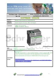
no. 207<br />
<strong>Electric</strong> <strong>motors</strong><br />
... and how to improve their control and<br />
protection<br />
Etienne Gaucheron<br />
Graduate electronics engineer by training. After a short period with<br />
Thomson he joined the VsD (Variable speed drives and starters)<br />
division of Telemecanique in 1970. He then completed his training at<br />
ENSAM (the national college for arts and vocational training) in Paris<br />
during his position with Telemecanique's after sales service.<br />
As a specialist in motor control, he was involved in the development<br />
of variable speed control for AC <strong>motors</strong>. He has gained a wide range<br />
of experience in various positions: systems platform engineer,<br />
product manager for machine tool drive products, product manager<br />
for drives for asynchronous <strong>motors</strong> (Altivar products) and manager of<br />
the VSD project marketing team.<br />
He is currently a motor control "applications" specialist within the<br />
advance development team for the <strong>Schneider</strong> <strong>Electric</strong> PCP (Power<br />
Control and Protection) division.<br />
ECT 207 first issue, October 2004
Cahier Technique <strong>Schneider</strong> <strong>Electric</strong> no. 207 / p.2
<strong>Electric</strong> <strong>motors</strong><br />
... and how to improve their control and protection<br />
Nowadays, apart from lighting devices, electric <strong>motors</strong> represent the<br />
largest loads in industry and commercial installations. Their function, to<br />
convert electrical energy into mechanical energy, means they are<br />
particularly significant in economic terms, and hence, they cannot be<br />
ignored by installation or machinery designers, installers or users.<br />
There are many types of motor in existence, but 3-phase asynchronous<br />
<strong>motors</strong>, and in particular squirrel cage <strong>motors</strong>, are the most commonly<br />
used in industry and in commercial buildings applications above a certain<br />
power level. Moreover, although they are ideal for many applications when<br />
controlled by contactor devices, the increasing use of electronic equipment<br />
is widening their field of application. This is the case for start/stop control<br />
with soft start/soft stop units, and when precise speed adjustment is also<br />
necessary with variable speed drives/regulators.<br />
However, slip-ring asynchronous <strong>motors</strong> are used for certain high power<br />
applications in industry, and single phase asynchronous <strong>motors</strong> remain<br />
suitable for limited power applications, mainly for buildings applications.<br />
The use of synchronous <strong>motors</strong>, known as brushless or permanent magnet<br />
<strong>motors</strong>, combined with converters is becoming increasingly common in<br />
applications requiring high performance levels, in particular in terms of<br />
dynamic torque (on starting or on a change of duty), precision and speed<br />
range.<br />
After presenting the various types of electric motor and their operating<br />
principles, this "Cahier Technique" describes the technical and operating<br />
features of asynchronous <strong>motors</strong>, covering in particular the main starting<br />
devices, speed control and braking methods. It provides a solid grounding<br />
for the reader to gain a good understanding of all the problems involved<br />
with motor control and protection.<br />
This "Cahier Technique" touches briefly on variable speed control of<br />
electric <strong>motors</strong>. However, this subject is covered more specifically in<br />
"Cahier Technique" CT 208 "Electronic starters and variable speed drives".<br />
Motor protection is the subject of another "Cahier Technique" currently in<br />
preparation.<br />
Contents<br />
1 Three-phase asynchronous <strong>motors</strong> 1.1 Operating principle p. 4<br />
1.2 Construction p. 6<br />
1.3 The various types of rotor p. 6<br />
2 Other types of electric motor 2.1 Single phase asynchronous <strong>motors</strong> p. 10<br />
2.2 Synchronous <strong>motors</strong> p. 10<br />
2.3 DC <strong>motors</strong> p. 14<br />
3 Operation of asynchronous <strong>motors</strong> 3.1 Squirrel cage <strong>motors</strong> p. 17<br />
3.2 Slip-ring <strong>motors</strong> p. 19<br />
3.3 Other speed variation systems p. 20<br />
4 Conclusion p. 22<br />
Cahier Technique <strong>Schneider</strong> <strong>Electric</strong> no. 207 / p.3
1 Three-phase asynchronous <strong>motors</strong><br />
This section covers 3-phase asynchronous<br />
<strong>motors</strong>, the most commonly used <strong>motors</strong> for<br />
driving machinery. The use of this type of motor<br />
has become the norm in a large number of<br />
applications because of its numerous<br />
advantages: it is standardized, rugged, easy to<br />
maintain and use, and inexpensive.<br />
Other types of motor are presented in section 2.<br />
Section 3 describes and compares the main<br />
starting devices, and speed control and braking<br />
methods associated with the <strong>motors</strong>.<br />
1.1 Operating principle<br />
The operating principle of an asynchronous<br />
motor is based on the creation of an induced<br />
current in a conductor when the conductor cuts<br />
the lines of force of a magnetic field, hence the<br />
name "induction motor". The combined action of<br />
this induced current and the magnetic field<br />
creates a motive force on the motor rotor.<br />
Let us take the example of a turn with short<br />
circuit ABCD, located in magnetic field B, and<br />
rotating around an axis xy (see Fig. 1 ).<br />
If, for example, we rotate the magnetic field<br />
clockwise, the turn is subject to a variable flux<br />
and becomes the source of an induced<br />
electromotive force which causes an induced<br />
current I (Faraday’s law).<br />
According to Lenz’s law, the direction of the<br />
current is such that it opposes the cause that<br />
produced it by its electromagnetic action. Both of<br />
direction of<br />
magnetic field<br />
direction of<br />
current<br />
(positive to<br />
negative)<br />
movements<br />
of the wire<br />
A<br />
x<br />
South<br />
D<br />
B<br />
I<br />
I<br />
North<br />
B<br />
F<br />
F<br />
y<br />
C<br />
Fig. 1: Creation of an induced current in a shorted turn<br />
Fig. 2: Fleming’s left hand rule to find the direction of<br />
the force<br />
the conductors are therefore subject to a Lorentz<br />
force F (also known as Laplace force), in the<br />
opposite direction to its relative displacement in<br />
relation to the field coil field.<br />
The left hand rule (action of the field on a<br />
current, see Figure 2 ) helps demonstrate the<br />
direction of the force F applied to each<br />
conductor.<br />
The thumb points in the direction of the<br />
movement field. The index finger indicates the<br />
direction of the field. The middle finger points in<br />
the direction of the induced current. The turn is<br />
therefore subject to a torque that causes it to<br />
rotate in the same direction as the coil field,<br />
called the rotating field. The turn therefore starts<br />
to rotate and the electromotive torque produced<br />
balances the resistive torque.<br />
Creation of the rotating field<br />
Three windings, geometrically offset by 120°, are<br />
each supplied by one of the phases of a 3-phase<br />
Cahier Technique <strong>Schneider</strong> <strong>Electric</strong> no 207 / p.4
AC supply (see Fig. 3 ). The windings have AC<br />
currents flowing through them that have the<br />
same electrical offset and that each produce a<br />
sinusoidal AC magnetic field. This field, which<br />
always follows the same axis, is at its maximum<br />
when the current in the winding is at its<br />
maximum.<br />
The field generated by each winding is the<br />
resultant of two fields rotating in opposite<br />
directions, each field having a constant value of<br />
120˚<br />
The flux corresponding to phase 3 is negative.<br />
The field is thus directed in the opposite direction<br />
to the coil.<br />
If the three diagrams are superimposed, it can<br />
be seen that:<br />
v The three fields rotating anticlockwise are<br />
offset by 120° and cancel one another out.<br />
v The three fields rotating clockwise are<br />
superimposed on one another. These fields are<br />
added together to form the rotating field with<br />
constant amplitude 3Hmax/2. It is a field with one<br />
pair of poles.<br />
This field performs one rotation during one<br />
period of the supply current. Its speed is<br />
dependent on the line supply frequency (f), and<br />
the number of pairs of poles (p). It is called the<br />
"synchronous speed".<br />
B3<br />
H3<br />
Ph3<br />
Ph2<br />
Ph1<br />
H2<br />
Fig. 3: Principle of a 3-phase asynchronous motor<br />
half that of the maximum field. At any instant t1<br />
in the period (see Fig. 4 ), the fields produced by<br />
each winding can be represented as follows:<br />
v Field H1 decreases. Its two component fields<br />
tend to move away from the axis OH1.<br />
v Field H2 increases. Its two component fields<br />
tend to move towards the axis OH2.<br />
v Field H3 increases. Its two component fields<br />
tend to move towards the axis OH3.<br />
B2<br />
Slip<br />
Motor torque can only exist if there is an induced<br />
current flowing in the turn. This torque is<br />
determined by the current flowing in the turn and<br />
can only exist if there is flux variation in this turn.<br />
There must therefore be a difference in speed<br />
between the turn and the rotating field. This is<br />
why an electric motor operating according to the<br />
principle we have just described is called an<br />
"asynchronous motor". The difference between<br />
the synchronous speed (Ns) and that of the turn<br />
(N) is called the "slip" and is expressed as a<br />
percentage of the synchronous speed.<br />
slip = [(Ns - N) / Ns] x 100<br />
During operation, the rotor current frequency is<br />
obtained by multiplying the supply frequency by<br />
the slip. The rotor current frequency is therefore<br />
at its maximum on starting.<br />
The steady state slip varies according to the<br />
motor load and the level of the supply voltage<br />
applied to it: the lower the motor load, the lower<br />
the slip; and if the motor is under-supplied the<br />
slip increases.<br />
Ph1<br />
H1 B1<br />
Ph1<br />
Ph1<br />
H1 max<br />
2<br />
H1<br />
H1 max<br />
2<br />
H2 max<br />
2<br />
H3 max<br />
2<br />
H3<br />
Ph3<br />
O<br />
Ph2<br />
Ph3<br />
O<br />
H2<br />
Ph2<br />
Ph3<br />
O<br />
H3 max<br />
2<br />
Ph2<br />
H2 max<br />
2<br />
Fig. 4: Fields generated by the three phases<br />
Cahier Technique <strong>Schneider</strong> <strong>Electric</strong> no 207 / p.5
Synchronous speed<br />
The synchronous speed of 3-phase<br />
asynchronous <strong>motors</strong> is directly proportional to<br />
the supply current frequency and inversely<br />
proportional to the number of pairs of poles<br />
comprising the stator.<br />
For example:<br />
Ns = 60 f/p<br />
Where:<br />
v Ns: synchronous speed in rpm<br />
v f: frequency in Hz<br />
v p: number of pairs of poles<br />
The rotation speeds of the rotating field, or<br />
synchronous speeds, according to the number of<br />
poles, are given in the table in Figure 5 for<br />
industrial frequencies of 50 Hz and 60 Hz and<br />
one other frequency (100 Hz).<br />
In practice it is not always possible to increase<br />
the speed of an asynchronous motor by<br />
supplying it with a higher frequency than that for<br />
which it is designed, even if the voltage is<br />
suitable. It is therefore necessary to check<br />
whether its mechanical and electrical design<br />
allows this.<br />
Number Speed of rotation in rpm<br />
of poles<br />
50 Hz 60 Hz 100 Hz<br />
2 3000 3600 6000<br />
4 1500 1800 3000<br />
6 1000 1200 2000<br />
8 750 900 1500<br />
10 600 720 1200<br />
12 500 600 1000<br />
16 375 540 750<br />
Fig. 5: Synchronous speeds according to the number<br />
of poles and the current frequency<br />
It should be noted that in view of the slip, the onload<br />
rotation speeds of asynchronous <strong>motors</strong> are<br />
slightly lower than the synchronous speeds<br />
indicated in the table.<br />
1.2. Construction<br />
A 3-phase squirrel cage asynchronous motor<br />
consists of two main parts: a field coil or stator<br />
and an armature or rotor.<br />
Stator<br />
This is the fixed part of the motor. A cast iron or<br />
light alloy frame surrounds a ring of thin<br />
laminations (around 0.5 mm thick) made of<br />
silicon steel. The laminations are insulated from<br />
one another by oxidation or an insulating<br />
varnish. The "lamination" of the magnetic circuit<br />
reduces losses via hysteresis and eddy currents.<br />
The laminations have slots in them for holding<br />
the stator windings that produce the rotating field<br />
(three windings for a 3-phase motor). Each<br />
winding is made up of a number of coils. The<br />
way these coils are joined to one another defines<br />
the number of pairs of poles of the motor, and<br />
thus the speed of rotation.<br />
Rotor<br />
This is the moving part of the motor. Like the<br />
magnetic circuit of the stator, it is made up of a<br />
stack of thin laminations insulated from one<br />
another, forming a keyed cylinder on the motor<br />
shaft. Two different technologies can be used for<br />
this part, which separate asynchronous <strong>motors</strong><br />
into two distinct families: those with a “squirrel<br />
cage” rotor and those with a wound rotor which<br />
are referred to as “slip-ring”.<br />
1.3. The various types of rotor<br />
Squirrel cage rotor<br />
There are several types of squirrel cage rotor.<br />
They are all designed as shown in the example<br />
in Figure 6 .<br />
These <strong>motors</strong> are (from the least common to the<br />
most widely used):<br />
c Resistive squirrel cage rotor<br />
The resistive rotor mainly exists in the single<br />
cage version (see later for the definition of the<br />
single cage motor). The cage is closed by two<br />
resistive rings (special alloy, small cross-section,<br />
stainless steel rings, etc). These <strong>motors</strong> have<br />
high slip at nominal torque. Their starting torque<br />
is high and the starting current is low<br />
(see Fig. 7 ). The efficiency of these <strong>motors</strong> is<br />
low due to the losses in the rotor.<br />
This type of motor is mainly used for<br />
applications in which it is useful to have some<br />
Cahier Technique <strong>Schneider</strong> <strong>Electric</strong> no 207 / p.6
Connecting<br />
box<br />
Fan end shield<br />
Stator<br />
winding<br />
Bearing<br />
Fan<br />
Fan cover<br />
Cage rotor<br />
Stator<br />
Bearing<br />
Shield end flange<br />
on shaft end side<br />
Fig. 6: Exploded view of a squirrel cage rotor motor<br />
C<br />
0<br />
Single cage rotor<br />
Double cage rotor<br />
Resistive cage rotor<br />
Fig. 7: Torque/speed curves for the various types of<br />
cage rotor (at Un)<br />
N<br />
slip in order to adapt the speed to the torque,<br />
for example:<br />
v In the case of several <strong>motors</strong> connected<br />
mechanically, across which the load must be<br />
distributed, such as rolling mill roller tables, or<br />
the drive system of a lifting crane<br />
v For winder/unwinder functions using Alquist (1)<br />
<strong>motors</strong> designed for this purpose<br />
v When a high starting torque with limited inrush<br />
current is needed (lifting hoists or conveyors).<br />
They are used to control the speed by modifying<br />
the voltage alone. But this application is on the<br />
decline, being increasingly replaced by<br />
frequency inverters. Although, in general, <strong>motors</strong><br />
are self-cooled, some resistive squirrel cage<br />
<strong>motors</strong> are force-cooled (separate motorization<br />
of their fans).<br />
1. This force-cooled asynchronous motor with high slip is<br />
used in speed control. Its stalling current is close to its<br />
nominal current, and its torque/speed characteristic falls<br />
very steeply. With a variable power supply it is possible to<br />
adapt this characteristic and adjust the motor torque<br />
according to the required traction.<br />
Cahier Technique <strong>Schneider</strong> <strong>Electric</strong> no 207 / p.7
c Single squirrel cage rotor<br />
Conductors are placed in the holes or slots<br />
around the edges of the rotor (on the outside of<br />
the cylinder created by the stacking of the<br />
laminations) and connected at either end by a<br />
metal ring. The motor torque generated by the<br />
rotating field is applied to these conductors. To<br />
make the torque regular, the conductors are at a<br />
slight angle in relation to the motor shaft. The<br />
whole assembly resembles a squirrel cage,<br />
hence the name of this type of rotor.<br />
The squirrel cage is generally fully molded, (only<br />
very large <strong>motors</strong> are made with conductors<br />
inserted in slots). Aluminum is pressure injected<br />
and the cooling fins, which are cast in the same<br />
operation, are used for short-circuiting the stator<br />
conductors.<br />
These <strong>motors</strong> have a relatively low starting<br />
torque and the current drawn on power-up is<br />
much higher than the nominal current (see<br />
Figure 7).<br />
On the other hand they have low slip at nominal<br />
current.<br />
These <strong>motors</strong> are mainly used at high power to<br />
improve the efficiency of installations on pumps<br />
and fans. They are also used with frequency<br />
inverters at variable speed. The torque and<br />
current problems on starting are thus fully<br />
resolved.<br />
c Double squirrel cage rotor<br />
This consists of two concentric cages, one outer,<br />
with a small cross-section, and highly resistive,<br />
and the other inner, with a large cross-section<br />
and lower resistance.<br />
v At the beginning of the starting phase, when<br />
the rotor current frequency is high, the resulting<br />
skin effect causes the whole of the rotor current<br />
to flow around the outer surface of the rotor and<br />
thus in a smaller surface area of the conductors.<br />
Thus, at the beginning of the starting phase,<br />
when the rotor current frequency is high, the<br />
current only flows in the outer cage. The torque<br />
produced by the resistive outer cage is high and<br />
the current inrush low (see Fig. 7 ).<br />
v At the end of the starting phase, the frequency<br />
decreases in the rotor and it is easier for the flux<br />
to flow through the inner cage. The motor then<br />
behaves very much as if it had been built with a<br />
single low resistance cage.<br />
In steady state the speed is only slightly lower<br />
than that of a single cage motor.<br />
c Rotor with deep slots<br />
This is the standard version.<br />
The rotor conductors are molded into the rotor<br />
slots which are trapezoidal shape, with the small<br />
side of the trapeze located on the outer surface<br />
of the rotor.<br />
Operation is similar to that of a double cage<br />
motor: the intensity of the rotor current varies<br />
inversely to its frequency. Thus:<br />
v At the beginning of the starting phase, torque<br />
is high and the current inrush is low.<br />
v In steady state the speed is more or less the<br />
same as that of a single cage motor.<br />
Wound rotor (slip-ring rotor)<br />
Identical windings to those of the stator are<br />
inserted in the slots around the outer edge of the<br />
rotor (see Fig. 8 ). The rotor is generally<br />
3-phase.<br />
One end of each of the windings is connected to<br />
a common point (star connection). The free ends<br />
can be connected to a centrifugal switch or to<br />
three insulated solid copper rings that form part<br />
of the rotor. The graphite-based brushes<br />
connected to the starting device rub against<br />
these rings.<br />
Depending on the values of the resistors inserted<br />
in the rotor circuit, this type of motor can develop<br />
a starting torque of up to 2.5 times the nominal<br />
torque.<br />
The current on starting is more or less<br />
proportional to the torque developed on the<br />
motor shaft.<br />
This solution is now being phased out in favor of<br />
electronic solutions combined with a standard<br />
squirrel cage motor. In fact, the latter solutions<br />
resolve maintenance issues (replacement of<br />
worn rotor power supply brushes, servicing of<br />
adjustment resistors), reduce the energy<br />
dissipated in these resistors and also<br />
significantly improve the efficiency of the<br />
installation.<br />
Cahier Technique <strong>Schneider</strong> <strong>Electric</strong> no 207 / p.8
Brush inspection<br />
door<br />
Connecting<br />
box<br />
Slip-ring<br />
end shield<br />
Brush<br />
Bearing<br />
Fan cover<br />
Slip rings<br />
Fan<br />
Bearing<br />
Wound rotor<br />
with open slots<br />
Stator<br />
Shield end flange<br />
on shaft end side<br />
Fig. 8: Exploded view of a slip-ring rotor moto<br />
Cahier Technique <strong>Schneider</strong> <strong>Electric</strong> no 207 / p.9
2 Other types of electric motor<br />
2.1 Single phase asynchronous <strong>motors</strong><br />
Although the single phase asynchronous motor<br />
is less widely used in industry than its 3-phase<br />
counterpart, it nevertheless represents a<br />
significant proportion of low power and buildings<br />
applications that use a 230 V single phase line<br />
supply.<br />
It is more bulky than a 3-phase motor of the<br />
same power rating.<br />
Moreover, its efficiency and its power factor are<br />
much lower than with the 3-phase motor and<br />
they vary considerably depending on the power<br />
and the manufacturer.<br />
Single phase <strong>motors</strong> up to ten or so kW are<br />
widely used in the United States.<br />
Construction<br />
Like the 3-phase motor, the single phase motor<br />
consists of two parts: the stator and the rotor.<br />
c Stator<br />
This consists of an even number of poles and its<br />
coils are connected to the line supply.<br />
c Rotor<br />
More often than not this is a squirrel cage rotor.<br />
Operating principle<br />
Let us consider a stator consisting of two<br />
windings, L1 and N, connected to the line supply<br />
(see Fig. 9 ).<br />
The single phase AC current creates a single AC<br />
field H in the rotor, which is the superimposition<br />
of two rotating fields H1 and H2 with the same<br />
value rotating in opposite directions.<br />
On stopping, because the stator is energized,<br />
these fields have the same slip in relation to the<br />
rotor and consequently produce two equal and<br />
opposite torques. The motor cannot start.<br />
A mechanical pulse on the rotor causes the slips<br />
to become unequal. One of the torques<br />
decreases while the other increases. The<br />
resulting torque causes the motor to start in the<br />
direction in which it has been set going.<br />
In order to solve this torque problem during the<br />
starting phase, a second coil, offset by 90°, is<br />
inserted in the stator. This auxiliary phase is<br />
powered by a phase angle device (capacitor or<br />
inductance). Once starting is complete the<br />
auxiliary phase can be disabled.<br />
Note: A 3-phase motor can also be used in<br />
single phase operation. The starting capacitor is<br />
then connected in series or in parallel with the<br />
unused winding.<br />
L1<br />
Stator<br />
winding<br />
H1<br />
Fig. 9: Operating principle of a single phase<br />
asynchronous motor<br />
H<br />
Rotor<br />
Stator<br />
winding<br />
H2<br />
N<br />
2.2 Synchronous <strong>motors</strong><br />
Construction<br />
Like the asynchronous motor, the synchronous<br />
motor consists of a stator and a rotor separated<br />
by the air gap. It differs from the asynchronous<br />
motor in that the flux in the air gap is not due to a<br />
component of the stator current: it is created by<br />
magnets or by the field coil current provided by<br />
an external DC source energizing a winding<br />
placed in the rotor.<br />
c Stator<br />
The stator consists of a housing and a magnetic<br />
circuit generally comprising silicon steel<br />
laminations and a 3-phase coil similar to that of<br />
an asynchronous motor supplied with 3-phase<br />
AC to produce a rotating field.<br />
c Rotor<br />
The rotor carries field magnets or coils through<br />
which a direct current flows and which create<br />
interposed North and South poles. Unlike<br />
asynchronous machines, the rotor rotates with<br />
no slip at the speed of the rotating field.<br />
There are therefore two different types of<br />
synchronous motor: magnet <strong>motors</strong> and wound<br />
rotor <strong>motors</strong>.<br />
Cahier Technique <strong>Schneider</strong> <strong>Electric</strong> no 207 / p.10
v With magnet <strong>motors</strong>, the motor rotor is fitted<br />
with permanent magnets (see Fig. 10 )<br />
(generally rare earth magnets), in order to<br />
achieve increased field strength in a small<br />
volume. The stator has three-phase windings.<br />
These <strong>motors</strong> can tolerate significant overload<br />
currents in order to achieve high-speed<br />
acceleration. They are always used with a<br />
variable speed drive, and these motor-drive<br />
assemblies are intended for specific markets<br />
such as robots or machine tools, for which<br />
smaller <strong>motors</strong>, acceleration and passband are<br />
essential.<br />
Stator<br />
winding<br />
Permanent<br />
magnet<br />
rotor<br />
(4 poles)<br />
10<br />
9<br />
11<br />
S<br />
8<br />
12<br />
Fig. 10: Cross-section of a permanent magnet motor<br />
v The second type of synchronous machine has<br />
a wound coil, and is a reversible machine that<br />
can operate as either a generator (alternator) or<br />
a motor. For many years these machines have<br />
been mainly used as alternators. Their use as<br />
<strong>motors</strong> was virtually confined to applications<br />
where it was necessary to drive loads at fixed<br />
speed despite relatively wide variations in their<br />
resistive torque.<br />
The development of direct (cycloconverters) or<br />
indirect frequency inverters operating with<br />
natural switching due to the ability of<br />
synchronous machines to provide reactive<br />
power, has enabled the creation of high<br />
performance, reliable variable speed electric<br />
drives that are particularly competitive in relation<br />
to competitors' solutions for power ratings over<br />
one megawatt.<br />
Although it is possible to find synchronous<br />
<strong>motors</strong> used industrially in power ratings ranging<br />
from 150 kW to 5 MW, it is above 5 MW that<br />
electric drives using synchronous <strong>motors</strong><br />
become virtually essential, for the most part<br />
combined with variable speed drives.<br />
7<br />
N<br />
N<br />
1<br />
6<br />
2<br />
S<br />
5<br />
3<br />
4<br />
Operating characteristics<br />
The motor torque of the synchronous machine is<br />
proportional to the voltage at its terminals,<br />
whereas that of the asynchronous machine is<br />
proportional to the square of that voltage.<br />
Unlike the asynchronous motor, it can work with<br />
a power factor equal to one or very close to it.<br />
The synchronous motor therefore has a number<br />
of advantages over the asynchronous motor with<br />
regard to its ability to be powered via the<br />
constant voltage/frequency line supply:<br />
v The speed of the motor is constant, regardless<br />
of the load.<br />
v It can supply reactive power and increase the<br />
power factor of an installation.<br />
v It can withstand relatively large voltage drops<br />
(around 50% due to its over-excitation<br />
properties) without stalling.<br />
However, the synchronous motor supplied<br />
directly by the constant voltage/frequency line<br />
supply has two disadvantages:<br />
v It has starting difficulties. If the motor is not<br />
combined with a variable speed drive, starting<br />
must be performed at no-load, either by DOL<br />
starting for small <strong>motors</strong>, or using a starting<br />
motor that drives it at a speed close to<br />
synchronous speed before direct connection to<br />
the line supply.<br />
v It may stall if the resistive torque exceeds its<br />
maximum electromagnetic torque. In this case,<br />
the entire start process must be repeated.<br />
Other types of synchronous motor<br />
To conclude this overview of industrial <strong>motors</strong>,<br />
we must also mention linear <strong>motors</strong>,<br />
synchronized asynchronous <strong>motors</strong> and stepper<br />
<strong>motors</strong>.<br />
c Linear <strong>motors</strong><br />
Their structure is identical to that of synchronous<br />
rotary <strong>motors</strong>: they consist of a stator (plate) and<br />
a rotor (forcer) which are in line. In general the<br />
plate moves along the forcer on a guide.<br />
This type of motor does away with all<br />
intermediate kinematics for converting the<br />
movement, which means there is no play or<br />
mechanical wear on this drive.<br />
c Synchronized asynchronous <strong>motors</strong><br />
These are induction <strong>motors</strong>. During the starting<br />
phase, the motor operates in asynchronous<br />
mode and when it has reached a speed close to<br />
synchronous speed, it switches to synchronous<br />
mode.<br />
If it has a high mechanical load, it can no longer<br />
operate in synchronous mode and returns to<br />
asynchronous mode. This feature is obtained by<br />
special construction of the rotor and is generally<br />
for low power <strong>motors</strong>.<br />
Cahier Technique <strong>Schneider</strong> <strong>Electric</strong> no 207 / p.11
c Stepper <strong>motors</strong><br />
The stepper motor is a motor that operates<br />
according to the electrical pulses supplying its<br />
coils. Depending on its electrical power supply, it<br />
may be:<br />
v Unipolar if its coils are always supplied in the<br />
same direction by a single voltage, hence the<br />
name unipolar.<br />
v Bipolar when its coils are supplied sometimes<br />
in one direction and sometimes in the other.<br />
They sometimes create a North pole, and<br />
sometimes a South pole, hence the name<br />
bipolar.<br />
Stepper <strong>motors</strong> can be of variable reluctance or<br />
magnet type or a combination of the two<br />
(see Fig. 11 ).<br />
The minimum angle of rotation between two<br />
modifications of the electrical pulses is called a<br />
step. A motor is characterized by the number of<br />
steps per revolution (that is, for 360°). The most<br />
common values are 48, 100 or 200 steps per<br />
revolution.<br />
The motor therefore rotates discontinuously. To<br />
improve the resolution, the number of steps may<br />
be increased in a purely electronic way (microstep<br />
operation). By varying the current in the<br />
coils in steps (see Fig. 12 ), a resulting field is<br />
created that slides from one step to another, thus<br />
effectively reducing the step.<br />
The circuits for micro-steps multiply the number<br />
of motor steps by 500, thus changing, for<br />
example, from 200 to 100,000 steps.<br />
The electronics can be used to control the<br />
chronology of these pulses and count the<br />
number of pulses. Stepper <strong>motors</strong> and their<br />
control circuits thus enable a shaft to rotate with<br />
a high degree of precision in terms of both speed<br />
and amplitude.<br />
Their operation is thus similar to that of a<br />
synchronous motor when the shaft is rotating<br />
continuously, which corresponds to specified<br />
frequency, torque and driven load inertia limits<br />
(see Fig. 13 ). If these limits are exceeded, the<br />
motor stalls, the effect of which is to stop the<br />
motor.<br />
Type Permanent Variable Hybrid<br />
magnet reluctance bipolar<br />
bipolar<br />
unipolar<br />
Characteristics 2 phases, 4 wires 4 phases, 8 wires 2 phases, 4 wires<br />
No. of steps/rev. 8 24 12<br />
Operating stages<br />
Step 1<br />
Intermediate state<br />
45˚ 15˚ 30˚<br />
Step 2<br />
Fig. 11: The three types of stepper motor<br />
Cahier Technique <strong>Schneider</strong> <strong>Electric</strong> no 207 / p.12
Accurate angular positioning is possible without<br />
a measurement loop. The small models of these<br />
<strong>motors</strong>, generally with power ratings of less than<br />
one kW, have a low voltage power supply. In<br />
industry, these <strong>motors</strong> are used for position<br />
control applications such as setting stops for<br />
cutting to length, controlling valves, optical or<br />
measurement devices, loading and unloading<br />
presses or machine tools, etc.<br />
The simplicity of this solution makes it<br />
particularly economical (no feedback loop).<br />
Magnet stepper <strong>motors</strong> also have the advantage<br />
of a standstill torque when there is no power<br />
supply.<br />
On the other hand, the initial position of the<br />
moving part has to be known and taken into<br />
account by the electronics in order to provide<br />
effective control.<br />
B1<br />
0.86<br />
0.5<br />
I1<br />
B1<br />
B2<br />
t<br />
I2<br />
B2<br />
t<br />
Fig. 12: Current steps applied to the coils of a stepper motor to reduce its step<br />
Torque<br />
Standstill<br />
torque<br />
Starting frequency limit<br />
Acceleration range<br />
Working torque limit<br />
Starting range<br />
Maximum step frequency<br />
Step frequency (Hz)<br />
Fig. 13: Maximum torque according to step frequency<br />
Cahier Technique <strong>Schneider</strong> <strong>Electric</strong> no 207 / p.13
2.3 DC <strong>motors</strong><br />
Separate field excitation DC <strong>motors</strong> are still<br />
sometimes used for driving machines at variable<br />
speed.<br />
These <strong>motors</strong> are very easy to miniaturize, and<br />
essential for very low powers and low voltages.<br />
They are also particularly suitable, up to high<br />
power levels (several megawatts), for speed<br />
variation with simple, uncomplicated electronic<br />
technologies for high performance levels<br />
(variation range commonly used from<br />
1 to 100).<br />
Their characteristics also enable accurate torque<br />
regulation, when operating as a motor or as a<br />
generator. Their nominal rotation speed, which is<br />
independent of the line supply frequency, is easy<br />
to adapt by design to suit all applications.<br />
They are however less rugged than<br />
asynchronous <strong>motors</strong> and much more<br />
expensive, in terms of both hardware and<br />
maintenance costs, as they require regular<br />
servicing of the commutator and the brushes.<br />
Construction<br />
A DC motor is composed of the following parts:<br />
c Field coil or stator<br />
This is a non-moving part of the magnetic circuit<br />
on which a winding is wound in order to produce<br />
a magnetic field. The electro-magnet that is<br />
created has a cylindrical cavity between its<br />
poles.<br />
c Armature or rotor<br />
This is a cylinder of magnetic laminations that<br />
are insulated from one another and<br />
perpendicular to the axis of the cylinder. The<br />
armature is a moving part that rotates round its<br />
axis, and is separated from the field coil by an air<br />
gap. Conductors are evenly distributed around<br />
its outer surface.<br />
c Commutator and brushes<br />
The commutator is integral with the armature.<br />
The brushes are fixed. They rub against the<br />
commutator and thus supply power to the<br />
armature conductors.<br />
same direction and are thus, according to<br />
Laplace's law, subject to a force. The conductors<br />
located under the other pole are subject to a<br />
force of the same intensity in the opposite<br />
direction. The two forces create a torque which<br />
causes the motor armature to rotate<br />
(see Fig. 14 ).<br />
When the motor armature is powered by a DC or<br />
rectified voltage supply U, it produces back<br />
emf E whose value is E = U – RI<br />
RI represents the ohmic voltage drop in the<br />
armature.<br />
The back emf E is linked to the speed and the<br />
excitation by the equation E = k ω Φ in which:<br />
v k is a constant specific to the motor<br />
v ω is the angular speed<br />
v Φ is the flux<br />
This equation shows that at constant excitation<br />
the back emf E (proportional to ω) is an image of<br />
the speed.<br />
The torque is linked to the field coil flux and the<br />
current in the armature by the equation:<br />
T = k Φ I<br />
If the flux is reduced, the torque decreases.<br />
There are two methods for increasing the speed.<br />
c Either increase the back emf E, and thus the<br />
supply voltage at constant excitation: this is<br />
known as "constant torque" operation.<br />
c Or decrease the excitation flux, and thus the<br />
excitation current, while keeping the supply<br />
voltage constant: this is known as "reduced flux"<br />
or "constant power" operation. This operation<br />
requires the torque to decrease as the speed<br />
increases (see Fig. 15 ). However, for high<br />
reduced flux ratios this operation requires<br />
Field coil pole<br />
Brush<br />
I<br />
Field coil pole<br />
Operating principle<br />
When the field coil is energized, it creates a<br />
magnetic field (excitation flux) in the air gap, in<br />
the direction of the radii of the armature. This<br />
magnetic field "enters" the armature from the<br />
North pole side of the field coil and "exits" the<br />
armature from the South pole side of the field<br />
coil.<br />
When the armature is energized, currents pass<br />
through the conductors located under one field<br />
coil pole (on the same side of the brushes) in the<br />
F<br />
F<br />
S<br />
i f<br />
Brush<br />
I<br />
Fig. 14: Production of torque in a DC motor<br />
N<br />
i f<br />
Cahier Technique <strong>Schneider</strong> <strong>Electric</strong> no 207 / p.14
specially adapted <strong>motors</strong> (mechanically and<br />
electrically) to overcome switching problems.<br />
The operation of this type of device (DC motor)<br />
is reversible:<br />
v If the load opposes the rotation movement (the<br />
load is said to be resistive), the device provides<br />
a torque and operates as a motor.<br />
v If the load is such that it tends to make the<br />
device rotate (the load is said to be driving) or it<br />
opposes the slow-down (stopping phase of a<br />
load with a certain inertia), the device provides<br />
electrical energy and operates as a generator.<br />
Various types of DC motor (see Fig. 16 )<br />
c Parallel excitation (separate or shunt)<br />
The coils, armature and field coil are connected<br />
in parallel or supplied via two sources with<br />
different voltages in order to adapt to the<br />
characteristics of the machine (e.g.: armature<br />
voltage 400 volts and field coil voltage<br />
180 volts).<br />
a: At constant torque<br />
b: At constant power<br />
Torque<br />
U=-U n<br />
U=0<br />
Torque<br />
T max<br />
Operation at:<br />
constant<br />
torque<br />
I = I max<br />
constant<br />
power<br />
T n<br />
I = I n<br />
U = -0.6U n<br />
U = -0.8 U n<br />
U = -0.4U n<br />
U=-0.2U n<br />
U = U n<br />
U =0.8U n<br />
U =0.6U n<br />
U =0.4U n<br />
U=0.2U n<br />
0 Speed<br />
0 N n<br />
N max<br />
U n ; Φ n<br />
Speed<br />
-T n<br />
I = -I n<br />
-T max<br />
I = -I max<br />
Fig. 15: Torque/speed curves for a separate field excitation motor<br />
a: Separate field excitation motor<br />
Supply 1<br />
c: Shunt wound motor<br />
Supply<br />
M<br />
Supply 2<br />
M<br />
b: Series wound motor<br />
d: Compound wound motor<br />
M<br />
Supply<br />
M<br />
Supply<br />
Fig. 16: Diagrams of the various types of DC motor<br />
Cahier Technique <strong>Schneider</strong> <strong>Electric</strong> no 207 / p.15
The direction of rotation is reversed by inverting<br />
one or other of the windings, generally by<br />
inverting the armature voltage due to the much<br />
lower time constants. Most bidirectional speed<br />
drives for DC <strong>motors</strong> operate in this way.<br />
c Series wound<br />
The design of this motor is similar to that of the<br />
separate field excitation motor. The field coil is<br />
connected in series to the armature coil, hence<br />
its name.<br />
The direction of rotation can be reversed by<br />
inverting the polarities of the armature or the field<br />
coil. This motor is mainly used for traction, in<br />
particular on trucks supplied by battery packs. In<br />
railway traction the old TGV (French high-speed<br />
train) motor coaches used this type of motor.<br />
More recent coaches use asynchronous <strong>motors</strong>.<br />
c Compound wound (series-parallel excitation)<br />
This technology combines the qualities of the<br />
series wound motor and the shunt wound motor.<br />
This motor has two windings per field coil pole.<br />
One is connected in parallel with the armature. A<br />
low current (low in relation to the working<br />
current) flows through it. The other is connected<br />
in series.<br />
It is an added flux motor if the ampere turns of<br />
the two windings add their effects. Otherwise it is<br />
a negative flux motor. But this particular<br />
mounting method is very rarely used as it leads<br />
to unstable operation with high loads.<br />
Cahier Technique <strong>Schneider</strong> <strong>Electric</strong> no 207 / p.16
3 Operation of asynchronous <strong>motors</strong><br />
3.1 Squirrel cage <strong>motors</strong><br />
Consequences of a voltage variation<br />
c Effect on the starting current<br />
The starting current varies with the supply<br />
voltage. If the supply voltage is higher during the<br />
starting phase, the current drawn at the moment<br />
of power-up increases. This current increase is<br />
aggravated by the saturation of the machine.<br />
c Effect on the speed<br />
When there are voltage variations, the<br />
synchronous speed is not modified, but for a<br />
motor under load, an increase in the voltage<br />
results in a slight decrease in the slip. In<br />
practical terms, this property cannot be used as,<br />
due to the saturation of the stator's magnetic<br />
circuit, the current drawn increases significantly<br />
that may cause an abnormal temperature rise of<br />
the machine, even during operation with a low<br />
load. On the other hand, if the supply voltage<br />
decreases, the slip increases, and the current<br />
drawn increases to provide the torque, with the<br />
resulting risk of temperature rise. Moreover,<br />
since the maximum torque decreases as the<br />
square of the voltage, the motor may stall if there<br />
is a significant decrease in the voltage.<br />
Consequences of a frequency variation<br />
c Effect on the torque<br />
As with any electrical machine, the torque of<br />
the asynchronous motor is of the type<br />
T = K I Φ<br />
(K = constant coefficient depending on the<br />
machine)<br />
In the equivalent diagram in figure 17 , coil L is<br />
that which produces the flux and Io is the<br />
magnetizing current.<br />
At first approximation, disregarding the<br />
resistance ahead of the magnetizing inductance<br />
(that is, for frequencies of a few Hertz) current Io<br />
is expressed as:<br />
Io = U / 2π L f<br />
and the flux will be expressed as:<br />
Φ = k Io<br />
The machine torque is therefore expressed as:<br />
T = K k Io I<br />
Io and I are the nominal currents for which the<br />
motor is designed.<br />
To avoid exceeding the limits, Io must be kept at<br />
its nominal value, which can only be achieved if<br />
the U/f ratio remains constant.<br />
Leakage<br />
inductance<br />
Energy<br />
losses<br />
Magnetic<br />
flux L<br />
inductance<br />
Io<br />
Stator<br />
Iron<br />
losses<br />
Rotor<br />
Active<br />
power<br />
Fig. 17: Equivalent diagram of an asynchronous motor<br />
Consequently, it is possible to obtain nominal<br />
torque and currents as long as the supply<br />
voltage U can be adjusted according to the<br />
frequency.<br />
When this adjustment is no longer possible, the<br />
frequency can always be increased, but the<br />
current Io decreases and the useful torque also<br />
decreases, as it is not possible to continually<br />
exceed the nominal current of the machine<br />
without risking a temperature rise.<br />
To achieve constant torque operation whatever<br />
the speed, the U/F ratio must be kept constant.<br />
This is what a frequency inverter does.<br />
c Effect on the speed<br />
The speed of rotation of an asynchronous motor<br />
is proportional to the frequency of the supply<br />
voltage. This property is often used to make<br />
specially designed <strong>motors</strong> operate at very high<br />
speed, for example with a 400 Hz supply<br />
(grinding machines, laboratory and surgical<br />
equipment, etc). It is also possible to achieve<br />
variable speed by adjusting the frequency, for<br />
example from 6 to 50 Hz (conveyor rollers, lifting<br />
equipment, etc).<br />
Adjusting the speed of 3-phase<br />
asynchronous <strong>motors</strong><br />
(subject described in detail in "Cahier<br />
Technique" no. 208)<br />
For many years, there were very few possibilities<br />
for adjusting the speed of asynchronous <strong>motors</strong>.<br />
Cahier Technique <strong>Schneider</strong> <strong>Electric</strong> no 207 / p.17
Squirrel cage <strong>motors</strong> were mostly used at their<br />
nominal speed. In practice only pole-changing<br />
<strong>motors</strong> or <strong>motors</strong> with separate stator windings,<br />
which are still frequently used nowadays, could<br />
provide several fixed speeds.<br />
Nowadays, with frequency inverters, squirrel<br />
cage <strong>motors</strong> are controlled at variable speed,<br />
and can thus be used in applications previously<br />
reserved for DC <strong>motors</strong>.<br />
Pole-changing <strong>motors</strong><br />
As we have already seen, the speed of a squirrel<br />
cage motor is dependent on the frequency of the<br />
line supply and the number of pairs of poles. It is<br />
therefore possible to obtain a motor with two or<br />
more speeds by creating combinations of coils in<br />
the stator that correspond to different numbers of<br />
poles.<br />
This type of motor only allows speed ratios of 1<br />
to 2 (4 and 8 poles, 6 and 12 poles, etc). It has<br />
six terminals (see Fig. 18 ).<br />
For one of the speeds the line supply is<br />
connected to the three corresponding terminals.<br />
For the second, the terminals are linked to one<br />
another, as the line supply is connected to the<br />
other three terminals.<br />
More often than not, at both high and low speed,<br />
starting is carried out by connecting directly to<br />
the line supply without using any special device<br />
(DOL starting).<br />
In some cases, if required by the operating<br />
conditions and permitted by the motor, the<br />
starting device automatically performs the<br />
change to low speed before initiating the change<br />
to high speed or before stopping.<br />
Depending on the currents drawn during the Low<br />
Speed -LSP- or High Speed -HSP- connections,<br />
protection may be provided by one thermal<br />
overload relay for both speeds or by two relays<br />
(one for each speed).<br />
In general, these <strong>motors</strong> have a low efficiency<br />
and a fairly low power factor.<br />
Motors with separate stator windings<br />
With this type of motor, which has two electrically<br />
independent stator windings, two speeds can be<br />
obtained in any given ratio. However their<br />
electrical characteristics are often affected by the<br />
fact that the LSP windings must withstand the<br />
mechanical and electrical stresses that result<br />
from operating the motor at HSP. Thus, this type<br />
of motor operating at LSP sometimes draws a<br />
higher current than at HSP.<br />
It is also possible to create three and four speed<br />
<strong>motors</strong> by coupling the poles to one or both of<br />
the stator windings. This solution requires<br />
additional connectors on the coils.<br />
∆/Y Dahlander connection (for constant torque)<br />
Low speed<br />
High speed<br />
Ph1<br />
Ph1<br />
1U<br />
2U<br />
2U<br />
2W<br />
1U 1W<br />
1W<br />
1V 2W<br />
1V<br />
Ph3 2V Ph2 Ph3<br />
2V<br />
Ph2<br />
Low speed<br />
2U 2V 2W<br />
1U 1V 1W<br />
Ph1 Ph2 Ph3<br />
High speed<br />
Ph1 Ph2 Ph3<br />
2U 2V 2W<br />
1U 1V 1W<br />
Y/YY Dahlander connection (for quadratic torque)<br />
Low speed<br />
High speed<br />
Ph1<br />
Ph1<br />
1U<br />
2U<br />
Low speed<br />
High speed<br />
Ph1 Ph2 Ph3<br />
2U<br />
1U<br />
1W<br />
2U<br />
2V 2W<br />
2U<br />
2V 2W<br />
1W<br />
Ph3<br />
2V<br />
2W<br />
1V<br />
Ph2<br />
2W<br />
Ph3<br />
1V<br />
2V<br />
Ph2<br />
1U 1V 1W<br />
Ph1 Ph2 Ph3<br />
1U 1V 1W<br />
Fig. 18: Different types of Dahlander connection<br />
Cahier Technique <strong>Schneider</strong> <strong>Electric</strong> no 207 / p.18
3.2 Slip-ring <strong>motors</strong><br />
Use of the rotor resistor<br />
The rotor resistor for this type of motor is used to<br />
define:<br />
v Its starting torque (see section 1)<br />
v Its speed<br />
Connecting a permanent resistor to the rotor<br />
terminals of a slip-ring motor lowers its speed<br />
(the higher the resistance the lower the speed).<br />
This is a simple solution for varying the speed.<br />
3.2.2. Adjusting the speed by the slip<br />
These rotor or "slip" resistors can be shortcircuited<br />
in several notches to obtain either a<br />
discontinuous adjustment of the speed, or<br />
gradual acceleration and complete starting of the<br />
motor. They must withstand the period of<br />
operation, in particular when they are intended to<br />
vary the speed. Hence, they are often quite<br />
sizeable and fairly costly.<br />
This extremely simple process is being used less<br />
and less as it has two major disadvantages:<br />
v During operation at low speed, a large<br />
proportion of the energy taken from the line<br />
supply is dissipated in straightforward losses in<br />
the resistors.<br />
v The speed obtained is not independent of the<br />
load, but varies with the resistive torque applied<br />
on the motor shaft by the machine (see Fig. 19 ).<br />
For a given resistance, the slip is proportional to<br />
the torque. Thus, for example, the reduction in<br />
speed obtained by a resistor can be 50% at full<br />
load and only 25% at half load, while the no-load<br />
speed remains virtually unchanged.<br />
If an operator continuously monitors the<br />
machine, he can set the speed in a certain zone<br />
for relatively high torques by modifying the<br />
resistance value on demand, but adjustment for<br />
low torques is virtually impossible. In fact, if the<br />
operator inserts a very high resistance in order to<br />
obtain a "low speed at low torque" point, the<br />
smallest variation in the resistive torque causes<br />
the speed to increase from zero to almost 100%.<br />
The characteristic is too unstable.<br />
For machines with special variation of the<br />
resistive torque according to the speed,<br />
adjustment can also prove impossible.<br />
Example of slip operation:<br />
For a machine which applies a resistive torque of<br />
0.8 Tn to the motor, different speeds can be<br />
obtained, represented by the sign • on the<br />
diagram in figure 19 .<br />
At steady torque, the speed decreases while the<br />
rotor resistance increases.<br />
Speed<br />
Slip<br />
operation<br />
zone<br />
Acceleration<br />
zone<br />
1<br />
0.75<br />
0.50<br />
Natural curve<br />
of the motor<br />
Curve with<br />
low rotor<br />
resistance<br />
0.25<br />
Curve with<br />
high rotor<br />
resistance<br />
0 0.5 0.8 1 1.5 2 Torque<br />
Fig. 19: Speed/torque curve with "slip" resistor<br />
Cahier Technique <strong>Schneider</strong> <strong>Electric</strong> no 207 / p.19
3.3 Other speed variation systems<br />
Variable voltage regulator<br />
This device is only used for low power<br />
asynchronous <strong>motors</strong>. It requires a resistive<br />
cage motor.<br />
Speed variation is achieved by increasing the<br />
motor slip by reducing the voltage.<br />
It is fairly widely used in ventilation, pump and<br />
compressor systems, applications for which its<br />
available torque characteristic provides<br />
satisfactory operation. However, as frequency<br />
inverters are now becoming very competitive,<br />
they are gradually replacing this solution.<br />
Metal drum<br />
Asynchronous<br />
motor<br />
Rotor<br />
DC powered coil<br />
Tachogenerator<br />
Other electromechanical systems<br />
The use of the electromechanical speed<br />
adjustment systems described below is on the<br />
decline since the generalization of electronic<br />
variable speed drives.<br />
c AC commutator <strong>motors</strong> (Schrage)<br />
These are special <strong>motors</strong>. Speed variation is<br />
achieved by varying the position of the brushes<br />
on the commutator in relation to the neutral line.<br />
c Eddy current drives<br />
This consists of a drum directly connected to the<br />
asynchronous motor operating at constant<br />
speed, and a rotor with a coil supplied with DC<br />
(see Fig. 20 ).<br />
The movement is transmitted to the output shaft<br />
by electromagnetic coupling. The slip of this<br />
assembly can be adjusted by adjusting the<br />
excitation of this coil.<br />
A built-in tachogenerator is used to control the<br />
speed with a high degree of accuracy.<br />
A ventilation system is used to evacuate the<br />
losses due to the slip.<br />
This principle was widely used in lifting<br />
equipment and in particular cranes. Its<br />
construction makes it a robust system with no<br />
wearing parts, which is suitable for intermittent<br />
operation and for power levels up to a hundred<br />
or so kW.<br />
c Ward Leonard set<br />
This device, which was widely used in the past,<br />
consists of a motor and a DC generator which<br />
supplies a DC motor (see Fig. 21 ).<br />
Speed control is achieved by regulating the<br />
excitation of the generator. A low control current<br />
enables powers of several hundred kW to be<br />
controlled in all the torque-speed quadrants. This<br />
type of drive was used on rolling mills and<br />
elevators for mining.<br />
Fig. 20: Schematic cross-section of an eddy current<br />
variable speed drive<br />
Line supply<br />
AC motor<br />
Generator<br />
Fig. 21: Diagram of a Ward Leonard set<br />
DC motor<br />
Output<br />
shaft<br />
This variable speed control solution was the<br />
most economical and provided the highest<br />
performance levels prior to the appearance of<br />
semiconductors, which have now rendered it<br />
obsolete.<br />
Mechanical and hydraulic speed drives<br />
Mechanical and hydraulic drives are still used<br />
today.<br />
Many solutions have been devised for<br />
mechanical drives (pulleys/belts, ball bearings,<br />
cones, etc). These drives have the disadvantage<br />
Cahier Technique <strong>Schneider</strong> <strong>Electric</strong> no 207 / p.20
of requiring meticulous maintenance and are<br />
difficult to use for servocontrol. These drives face<br />
strong competition from frequency inverters.<br />
Hydraulic drives are still very widely used for<br />
specific applications. They are characterized by<br />
significant output powers and the ability to<br />
develop high torques at zero speed continuously.<br />
In industry they are mainly to be found in<br />
servocontrol applications.<br />
This type of drive will not be described here as it<br />
does not fall within the framework of this study.<br />
Cahier Technique <strong>Schneider</strong> <strong>Electric</strong> no 207 / p.21
4 Conclusion<br />
The following table gives a quick overview of all<br />
the available electric <strong>motors</strong>, together with their<br />
main characteristics and the areas in which they<br />
are used.<br />
We must stress the importance of 3-phase<br />
squirrel cage asynchronous <strong>motors</strong>. The term<br />
"standard" applied to this type of motor is now<br />
even more appropriate since they are ideal for<br />
uses that have arisen from the development of<br />
electronic devices for variable speed control.<br />
Type of motor Squirrel cage asynchronous Slip-ring Synchronous Stepper DC<br />
3-phase single phase asynchronous wound rotor rare earth<br />
rotor<br />
Motor cost Low Low High High High Low High<br />
Dust and damp Standard Possible On request, On request, Standard Standard Possible,<br />
proof motor expensive expensive very expensive<br />
DOL starting Easy Easy Special starting Impossible Not possible Not possible Not possible<br />
device<br />
above a few kW<br />
Variable speed Easy Very rare Possible Frequent Always Always Always<br />
control<br />
Cost of variable Increasingly Very Economical Very Fairly Very Very<br />
speed control economical economical economical economical economical economical<br />
solution<br />
Speed control Increasingly Very low Average High Very high Medium to high High to very<br />
performance higher high<br />
Use Constant or Constant speed Constant or Constant or Variable speed Variable speed Variable speed<br />
variable speed for the majority variable speed variable speed<br />
Industrial use Universal For low power Decreasing High power Machine tools, Open loop Decreasing<br />
ratings ratings at high dynamics position control,<br />
medium voltage<br />
for low powers<br />
Cahier Technique <strong>Schneider</strong> <strong>Electric</strong> no 207 / p.22
<strong>Schneider</strong> <strong>Electric</strong><br />
Direction Scientifique et Technique,<br />
Service Communication Technique<br />
F-38050 Grenoble cedex 9<br />
Fax: 33 (0)4 76 57 98 60<br />
E-mail : fr-tech-com@schneider-electric.com<br />
DTP: SEDOC Meylan.<br />
Transl.: Lloyd International - Tarporley - Cheshire - GB.<br />
Editor: <strong>Schneider</strong> <strong>Electric</strong><br />
- 20 € -<br />
© 2004 <strong>Schneider</strong> <strong>Electric</strong><br />
10-04