P22 2004 Manual - Wood Pellet Stoves
P22 2004 Manual - Wood Pellet Stoves
P22 2004 Manual - Wood Pellet Stoves

Create successful ePaper yourself
Turn your PDF publications into a flip-book with our unique Google optimized e-Paper software.
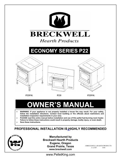
ECONOMY SERIES <strong>P22</strong><br />
<strong>P22</strong>FSL <strong>P22</strong>I <strong>P22</strong>FSL<br />
OWNER’S MANUAL<br />
• WARNING: If your appliance is not properly installed a house fire may result. For your safety,<br />
follow the installation directions. Contact local building or fire officials about restrictions and<br />
installation inspection requirements in your area.<br />
• PLEASE read this entire manual before installation and use of this pellet fuel-burning room heater.<br />
Failure to follow these instructions could result in property damage, bodily injury, or even death.<br />
• Save these instructions.<br />
PROFESSIONAL INSTALLATION IS HIGHLY RECOMMENDED<br />
Manufactured by<br />
Breckwell Hearth Products<br />
Eugene, Oregon<br />
Grand Prairie, Texas<br />
www.breckwell.com<br />
©BRECKWELL HEARTH PRODUCTS<br />
C-L-067 8/04<br />
www.<strong>Pellet</strong>King.com
2<br />
INTRODUCTION<br />
Thank you for purchasing the Breckwell <strong>Pellet</strong> Burning Stove. You are now prepared to burn<br />
wood in the most efficient, convenient way possible. To achieve the safest, most efficient and<br />
most enjoyable performance from your stove, you must do three things: 1) Install it properly;<br />
2) Operate it correctly; and 3) Maintain it regularly. The purpose of this manual is to help you<br />
do all three.<br />
PLEASE read this entire manual before installation and use of this pellet fuel-burning<br />
room heater. Failure to follow these instructions could result in property damage,<br />
bodily injury or even death.<br />
Keep this manual handy for future reference.<br />
Your Breckwell <strong>P22</strong> comes as a fireplace insert or as a freestanding stove with legs or a<br />
pedestal.<br />
This stove has been independently tested to ASTM E1509-95 Standard Specification for<br />
Room Heaters, <strong>Pellet</strong> Fuel Burning Type 1, UL 1482-1998 Standard for Solid Fuel Room<br />
Heaters, Oregon Administrative Rules for Mobile Homes (814-23-900 through 814-23-909)<br />
and Installation as a Stove Heater.<br />
This pellet stove, when installed, must be electrically grounded in accordance with local<br />
codes, or in the absence of local codes, with the National Electrical Code, ANSI/NFPA 70.<br />
This appliance is designed specifically for use only with pelletized wood. It is designed for<br />
residential installation according to current national and local building codes as a freestanding<br />
room heater. It is also approved as a mobile home heater which is designed for connection to<br />
an outside combustion air source.<br />
The stove will not operate using natural draft or without a power source for the blower<br />
systems and fuel feed system and must not be burned with any type of coal (see PROPER<br />
FUEL).<br />
This stove is designed to provide the optimum proportions of fuel and air to the fire in order to<br />
burn free of smoke and soot. Any blockage of the air supply to or from the stove will seriously<br />
degrade its performance and will be evidenced by a smoking exhaust and a sooting window.<br />
For best operation the ash content of the pellet fuel should be less than 1% and the calorific<br />
value approximately 8200 BTU/LB. Avoid high ash content fuels because this will rapidly fill<br />
up the burn pot and eventually cut off the combustion air supply.<br />
Commercial and industrial installations of Breckwell <strong>Pellet</strong> <strong>Stoves</strong> should not be used since<br />
operational control is often not well managed in these settings.<br />
IMPORTANT INFORMATION<br />
Model: _____<strong>P22</strong>___________________<br />
Style: ____________________________<br />
Serial Number:_____________________<br />
Purchase Date: ____________________<br />
Purchased From:___________________<br />
___________________<br />
___________________<br />
www.<strong>Pellet</strong>King.com<br />
MAIL YOUR WARRANTY CARD TODAY<br />
To receive full warranty coverage, you will<br />
need to show evidence of the date you<br />
purchased your stove. We suggest that<br />
you attach your sales invoice to this page,<br />
and fill in the form on the left, so that you<br />
will have all the information you need in<br />
one place should the need for service or<br />
information occur.
SAFETY PRECAUTIONS 3<br />
• Do not operate your stove if you<br />
smell smoke coming from it. Turn it off,<br />
monitor it, and call your dealer.<br />
• Never use gasoline, gasolinetype<br />
lantern fuel, kerosene, charcoal lighter<br />
fluid, or similar liquids to start or “freshen<br />
up” a fire in this stove. Keep all such liquids<br />
well away from the stove while in use.<br />
• Never block free airflow through<br />
the open vents of the stove.<br />
• Keep foreign objects out of the<br />
hopper.<br />
• Do not throw this manual away.<br />
This manual has important operating and<br />
maintenance instructions that you will need at<br />
a later time. Always follow the instructions in<br />
this manual.<br />
• Do not place clothing or other<br />
flammable items on or near the stove.<br />
• Never try to repair or replace any<br />
part of the stove unless instructions are<br />
given in this manual. All other work should<br />
be done by a trained technician.<br />
• The stove will not operate during<br />
a power outage. If an outage does occur,<br />
check the stove for smoke spillage and<br />
open a window if any smoke spills into the<br />
room.<br />
• Disconnect the power cord<br />
before performing any maintenance or<br />
repairs on the stove.<br />
NOTE: Turning the stove “off” does not<br />
disconnect all power from the stove.<br />
• Do not unplug the stove if you<br />
suspect a malfunction. Turn the stove off,<br />
periodically inspect it, and call your dealer.<br />
• Contact your local building<br />
officials to obtain a permit and information<br />
on any installation restrictions or inspection<br />
requirements in your area. Notify your<br />
insurance company of this stove as well.<br />
• This unit must be properly<br />
installed to prevent the possibility of a<br />
house fire. The instructions must be strictly<br />
adhered to. Do not use makeshift methods<br />
or compromise in the installation.<br />
• Allow the stove to cool before<br />
carrying out any maintenance or cleaning.<br />
Ashes must be disposed in a metal<br />
container with a tight lid and placed on a<br />
no combustible surface well away from the<br />
home structure.<br />
• This stove must be connected to<br />
a standard 120 V., 60 Hz grounded<br />
electrical outlet. Do not use an adapter<br />
plug or sever the grounding plug. Do not<br />
route the electrical cord underneath, in<br />
front of, or over the stove.<br />
• The exhaust system should be<br />
checked, at a minimum, at least twice a<br />
year for any build up of soot or creosote.<br />
• The viewing door must be closed<br />
and latched during operation.<br />
• Do not operate the stove if the<br />
flame becomes dark and sooty or if the<br />
burnpot overfills with pellets. Turn the stove<br />
off, periodically inspect it, and call your<br />
dealer.<br />
• Hot while in operation. Keep<br />
children, clothing, and furniture away. Contact<br />
may cause skin burns. Educate all children of<br />
the danger of a high temperature stove.<br />
Young children should be supervised when<br />
they are in the same room as the stove.<br />
• If the stove is installed in a room<br />
without air conditioning, or in an area where<br />
direct sunlight can shine on the unit, it is<br />
possible this can cause the temperature of<br />
the stove to rise to operational levels; one of<br />
the sensors could then make the stove start<br />
on its own. It is recommended that the stove<br />
be unplugged when not in use for extended<br />
amounts of time (i.e. during the summer<br />
months).<br />
• The exhaust system must be<br />
completely airtight and properly installed. The<br />
pellet vent joints must be sealed with RTV<br />
500°F. (260°C.) silicone sealant, and with UL-<br />
181-AP foil tape.<br />
• Your stove requires periodic<br />
maintenance and cleaning. Failure to<br />
maintain your stove may lead to smoke<br />
spillage in your home.<br />
• This stove is designed and<br />
approved for pelletized wood fuel only. Any<br />
other type of fuel burned in this heater will<br />
void the warranty and safety listing.<br />
• When installed in a mobile home,<br />
the stove must be bolted to the floor, have<br />
outside air, and NOT BE INSTALLED IN A<br />
BEDROOM (Per H.U.D. requirements).<br />
Check with local building officials.<br />
• Breckwell Hearth Products<br />
grants no warranty, implied or stated, for<br />
the installation or maintenance of your<br />
stove, and assumes no responsibility of<br />
any consequential damage(s).<br />
www.<strong>Pellet</strong>King.com
4<br />
TABLE OF CONTENTS<br />
INTRODUCTION --------------------------------------------------------------------------------------------- 2<br />
SAFETY PRECAUTIONS ---------------------------------------------------------------------------------- 3<br />
SPECIFICATIONS ------------------------------------------------------------------------------------------- 5<br />
INSTALLATION --------------------------------------------------------------------------------------------- 5<br />
Preparation ----------------------------------------------------------------------------------------- 5<br />
Clearances ----------------------------------------------------------------------------------------- 5<br />
Combustion Air Supply -------------------------------------------------------------------------- 6<br />
When Outside Air Is Not Used ----------------------------------------------------------------- 6<br />
Venting ----------------------------------------------------------------------------------------------- 6<br />
Freestanding Installations ---------------------------------------------------------------------- 7<br />
Insert Installations -------------------------------------------------------------------------------- 10<br />
Electrical Installation ------------------------------------------------------------------------------ 13<br />
Special Mobil Home Requirements ---------------------------------------------------------- 13<br />
OPERATION --------------------------------------------------------------------------------------------------- 14<br />
Proper Fuel ----------------------------------------------------------------------------------------- 14<br />
Pre-Start-Up Check ------------------------------------------------------------------------------- 14<br />
Building a Fire ------------------------------------------------------------------------------------- 14<br />
The HotRod Automatic Fire Starter -------------------------------------------------------- 14<br />
Panel Controls ------------------------------------------------------------------------------------- 14<br />
Opening Door -------------------------------------------------------------------------------------- 15<br />
Room Air Fan -------------------------------------------------------------------------------------- 15<br />
Re-Starting a Warm Stove ---------------------------------------------------------------------- 15<br />
If Stove Runs Out Of <strong>Pellet</strong>s -------------------------------------------------------------------- 16<br />
Damper Control ------------------------------------------------------------------------------------ 16<br />
Refueling --------------------------------------------------------------------------------------------- 16<br />
Breckwell Maintenance Tool -------------------------------------------------------------------- 16<br />
Shutdown Procedure ----------------------------------------------------------------------------- 16<br />
Safety Features ------------------------------------------------------------------------------------ 16<br />
Optional Thermostat ------------------------------------------------------------------------------ 17<br />
Thermostat Installation -------------------------------------------------------------------------- 17<br />
(Please Read This) Operating Safety Precautions -------------------------------------- 18<br />
MAINTENANCE ---------------------------------------------------------------------------------------------- 19<br />
Ash Removal ---------------------------------------------------------------------------------------- 19<br />
Ash Disposal ---------------------------------------------------------------------------------------- 19<br />
Vacuum Use ---------------------------------------------------------------------------------------- 19<br />
Cleaning ---------------------------------------------------------------------------------------------- 19<br />
Blowers ---------------------------------------------------------------------------------------------- 20<br />
Chimney Cleaning -------------------------------------------------------------------------------- 21<br />
Recommended Maintenance Schedule ----------------------------------------------------- 21<br />
Removal & Replacement of Broken Door Glass ------------------------------------------ 21<br />
TROUBLE SHOOTING GUIDE -------------------------------------------------------------------------- 22<br />
Smoke Smell or Soot Build-Up ---------------------------------------------------------------- 27<br />
ELECTRICAL DIAGRAM --------------------------------------------------------------------------------- 28<br />
REPLACEMENT PARTS LIST -------------------------------------------------------------------------- 29<br />
www.<strong>Pellet</strong>King.com
INSTALLATION 5<br />
SPECIFICATIONS<br />
FREESTANDING:<br />
Width: 21 ½”<br />
Height: 28 ½” (with legs or pedestal)<br />
Depth: 24”<br />
Weight: 185 lbs.<br />
Pedestal: 40 lbs.<br />
Legs: 13 lbs.<br />
Flue size: 3” or 4”<br />
Hopper Capacity: Up to 45 lbs.<br />
(this can vary widely depending on pellet size, length, and diameter)<br />
EPA status: exempt<br />
Burn time: 1 lb. to 4 ½ lbs. per hour<br />
BTU range: 8,200 to 40,000<br />
Approved installations: mobile home, alcove, conventional<br />
FIREPLACE INSERT:<br />
Width: 21 ½” (With flashing: 39”)<br />
Height: 20” (With flashing: 30”)<br />
Depth: 24” (In fireplace: 10 ¾”)<br />
Weight: 185 lbs.<br />
Flashing: 13 lbs.<br />
Flue size: 3” or 4”<br />
Hopper Capacity: Up to 45 lbs.<br />
(this can vary widely depending on pellet size, length, and diameter)<br />
EPA status: exempt<br />
Burn time: 1 lb. to 4 ½ lbs. per hour<br />
BTU range: 8,200 to 40,000<br />
Approved installations: zero-clearance, masonry, as a built-in<br />
PREPARATION<br />
FIGURE 1<br />
ALCOVE CLEARANCES<br />
FIGURE 2<br />
Factory packaging must be removed, and some minor assembly work is required<br />
prior to installation. Access to the rear of the stove is necessary.<br />
The circuit board/control panel must be unpacked and installed in the side<br />
flashing on the insert or side panel on the freestanding.<br />
(See installation instructions provided with the circuit board)<br />
NOTE: Normally, your dealer will perform these functions.<br />
CLEARANCES<br />
The Breckwell <strong>P22</strong> Freestanding has been tested and listed for installation in<br />
residential, mobile home and alcove applications.<br />
The <strong>P22</strong> Insert is approved for installation into code complying masonry<br />
fireplaces. It is also approved for use in listed factory built fireplaces (UL 127)<br />
and standard residential built-ins (see As A Built-In Fireplace), including Mobile<br />
Home built-in installations, of the following description: all brands at least 34”<br />
wide and 20 ½” high.<br />
FLOOR PROTECTION: Freestanding installations, minimum 21” wide by 28”<br />
deep. The stove must be placed on a continuous (grouted joints) noncombustible<br />
material such as ceramic tile, cement board, brick, 3/8” millboard or equivalent,<br />
or other approved or listed material suited for floor protection.<br />
THE MATERIAL(S) USED MUST HAVE, OR COMBINE TO HAVE, A MINIMUM<br />
INSULATIVE RATING OF ‘R1’.<br />
NOTE: ceramic tile, or any tile, requires a continuous sheet beneath to prevent<br />
the possibility of embers falling through to the combustible floor if cracks or<br />
separation should occur in the finished surface, this would include floor<br />
protection for Built-in raised hearths. Check local codes for approved<br />
alternatives.<br />
Clearances are measured from the sides, back and face (door opening) or stove<br />
body (refer to fig. 4).<br />
DO NOT USE MAKESHIFT MATERIALS OR COMPROMISES IN THE<br />
INSTALLATION OF THIS UNIT.<br />
INSTALL VENT WITH CLEARANCES SPECIFIED BY THE VENT<br />
MANUFACTURER.<br />
FIGURE 3<br />
FLOOR PROTECTION<br />
FIGURE 4<br />
www.<strong>Pellet</strong>King.com
6<br />
INSTALLATION<br />
COMBUSTION AIR SUPPLY<br />
For a mobile home installation the stove must be connected to an<br />
outside source of combustion air. A 2” inside diameter metallic pipe,<br />
either flexible or rigid, may be attached to the inlet at the stove’s rear<br />
(refer to figures 5a, 5b, and 6). A rodent guard (minimum ¼” wire<br />
mesh)/wind hood must be used at the terminus (refer to figure 7). All<br />
connections must be secured and airtight by either using the<br />
appropriately sized hose clamp and/or UL-181-AP foil tape.<br />
For mobile home installations only: 2” inside diameter pipe may<br />
be used for the first 5 feet of combustion air supply run. From 5 to 10<br />
feet use 2 ¾” inside diameter pipe. No combustion air supply may<br />
exceed 10 feet.<br />
Sources of Outside Combustion Air<br />
a. In fireplaces<br />
• Chimney top.<br />
• Ash clean out door.<br />
b. For freestanding installations<br />
• A hole in floor near stove rear terminating only in a<br />
ventilated crawl space.<br />
• A hole in the wall behind the stove.<br />
FIGURE 5a<br />
WHEN OUTSIDE AIR IS NOT USED<br />
If outside air is not used, it is important that combustion air is easily<br />
available to the air inlet. A closeable outside air register can be used<br />
in tightly insulated homes. In insert installations, flashing vents<br />
should not be restricted. The flashing should not necessarily seal the<br />
fireplace face.<br />
VENTING<br />
The Breckwell <strong>P22</strong> Freestanding is certified for use with listed TYPE<br />
L-Vent, 3” or 4” diameter in size. The stove was tested with Simpson<br />
Duravent brand. Class “A” chimney is not required. Refer to the<br />
instructions provided by the vent manufacturer, especially when<br />
passing through a wall, ceiling or roof.<br />
FIGURE 5b<br />
This is a pressurized exhaust system. All vent connector joints must<br />
be sealed with 500°F (260°C) RTV silicone sealant to ensure<br />
consistent performance and avoid smoke spillage. All horizontal<br />
connector joints must be sealed with UL-181-AP foil tape. We<br />
recommend that all vertical vent connector joints be secured with a<br />
minimum of 3 screws.<br />
DO NOT CONNECT THIS UNIT TO A CHIMNEY FLUE SERVING<br />
ANOTHER APPLIANCE.<br />
DO NOT INSTALL A FLUE DAMPER IN THE EXHAUST VENTING<br />
SYSTEM OF THIS UNIT.<br />
INSTALL VENT AT CLEARANCES SPECIFIED BY THE VENT<br />
MANUFACTURER.<br />
FIGURE 6<br />
FIGURE 7<br />
www.<strong>Pellet</strong>King.com
INSTALLATION 7<br />
Equivalent Vent Length (EVL)<br />
The longer the run of pipe in your installation (both with inserts and<br />
freestandings), the more restriction there is in the system. Therefore,<br />
larger diameter pipe should be used.<br />
• Use 4” pipe if you have more than 15 feet of equivalent vent<br />
length.<br />
• Horizontal runs shall not exceed 10 feet of EVL.<br />
• It is recommended that vertical runs be a minimum of 8 feet.<br />
• To calculate EVL, use the following conversions:<br />
90º elbow or “T” = 5 equivalent feet<br />
45º elbow = 3 equivalent feet<br />
Horizontal Pipe Run<br />
Vertical Pipe Run<br />
= 1 equivalent foot per actual foot<br />
= 0.5 equivalent foot per actual foot<br />
NOTE: At altitudes above 3,000 feet, we suggest the use of 4”<br />
diameter vent at an EVL of 7 feet or more.<br />
FREESTANDING INSTALLATIONS<br />
A. ASSEMBLING PEDESTAL OR LEG SET<br />
If using a pedestal, follow the instructions inside the Breckwell <strong>P22</strong><br />
Pedestal Set Part # A-22-P (refer to figure 8).<br />
If using cast legs, follow the instructions inside the Breckwell <strong>P22</strong> Leg<br />
Set Part # A-CGL-22 or # A-CL-22.<br />
FIGURE 8<br />
Legs are installed by using the four bolts provided in the kit into the<br />
four holes under the stove at each corner, thread on nuts from the top<br />
and tighten. Make sure to save the hole plugs.<br />
NOTE: If converting from legs to pedestal the hole plugs must be<br />
installed in the unused holes.<br />
B. HORIZONTALLY THROUGH WALL (refer to Figure 9)<br />
NOTE: Follow L-Vent chimney manufacturer’s instructions.<br />
1. Position stove, adhering to clearances shown in Figures 1 & 2.<br />
2. Locate position of hole in wall; directly behind stove exhaust vent<br />
(refer to figure 5).<br />
3. Always maintain 3” clearance from combustible materials.<br />
4. Install L-Vent wall thimble per L-Vent manufacturer’s instructions.<br />
5. Attach enough piping to penetrate and extend at least 6” beyond<br />
exterior walls. An 8-foot vertical pipe run is suggested where<br />
possible to reduce the possibility of smoke spillage in the event of<br />
a loss of negative pressure.<br />
6. Attach cap and seal outside wall thimbles with non-hardening<br />
waterproof mastic.<br />
7. Termination should not be located so that hot exhaust gases can<br />
ignite trees, shrubs, or grasses or be a hazard to children.<br />
Exhaust gases can reach temperatures of 500ºF and cause<br />
serious burns if touched.<br />
FIGURE 9<br />
Locate terminations: a) not less than 3 feet above any forced air<br />
inlet located within 10 feet; b) not less than 4 feet below or<br />
horizontally from, or one foot above, any door, window or gravity<br />
air inlet into any building; c) not less than two feet from an<br />
adjacent building and not less than 7 feet above grade when<br />
located adjacent to a public walkway. Mobile home installations<br />
must use a spark arrester.<br />
www.<strong>Pellet</strong>King.com
8<br />
INSTALLATION<br />
C. VERTICALLY WITH NEW CHIMNEY SYSTEM (Refer to<br />
Figure 10)<br />
NOTE: Follow L-Vent chimney manufacturer’s instructions.<br />
OPTION: To achieve a center vertical installation a 45º elbow<br />
and a clean-out tee can be used to offset the pipe from the<br />
exhaust outlet to the rear center of the stove.<br />
OPTION: Install L-Vent elbow in place of clean-out tee. Locate<br />
stove. Drop plumb bob to center of tee outlet, mark point on<br />
ceiling. Install ceiling support and L-Vent pipe per L-Vent<br />
manufacturer’s instructions.<br />
1. Always maintain 3” clearance from combustible materials.<br />
When passing through additional floors or ceilings, always<br />
install firestop spacer.<br />
2. After lining up for hole in roof, cut either around or square<br />
hole in roof, always 3” larger all the way around pipe. Install<br />
upper edge and sides of flashing under roofing materials,<br />
nail to the roof along upper edge. Do not nail lower edge.<br />
Seal nail heads with non-hardening waterproof mastic.<br />
3. Apply non-hardening, waterproof mastic where the storm<br />
collar will meet the vent and flashing. Slide storm collar<br />
down until it sits on the flashing. Seal and install cap. Mobile<br />
home installations must use a spark arrester.<br />
D. VERTICALLY INTO EXISTING CHIMNEY SYSTEM<br />
Adapters are available to adapt from 3” L-Vent to 6” or 8” Class-A<br />
chimney. (Figure 11a)<br />
FIGURE 10<br />
As an alternative, 3” or 4” L-Vent can be run inside existing<br />
chimney to termination. (Figure 11b)<br />
This is the preferred method.<br />
Follow guidelines for equivalent vent length.<br />
FIGURE 11a<br />
FIGURE 11b<br />
www.<strong>Pellet</strong>King.com
E. VERTICALLY INTO EXISTING MASONRY<br />
FIREPLACE<br />
NOTE: Follow L-Vent chimney manufacturer’s instructions.<br />
1. Have the masonry chimney inspected by a qualified<br />
chimney sweep or installer to determine its structural<br />
condition.<br />
2. You will need a pipe length equal to the chimney<br />
height from the hearth. If outside combustion air is to<br />
be used, you will need a pipe length equal to the<br />
chimney height plus 18 inches.<br />
3. Install a blanking plate and the chimney pipe, and if<br />
used the outside air pipe, as shown in Figure 12.<br />
4. Attach the L-Vent adapter, a section of pipe and clean<br />
out tee, making sure the clean out tee is centered in<br />
the chimney flue area. Use RTV, metallic tape, and a<br />
minimum of three self-taping screws at all joint<br />
connections to ensure a tight seal.<br />
5. Position the stove, adhering to the clearances in<br />
Figures 1 & 2.<br />
6. Measure and build chimney top plate. Cut out holes for<br />
chimney pipe, and if used the outside air pipe. Install<br />
and seal with non-hardening mastic to prevent water<br />
leakage. Install vent cap.<br />
INSTALLATION 9<br />
F. INSTALLATION THROUGH SIDE OF MASONRY<br />
CHIMNEY<br />
NOTE: Follow L-Vent chimney manufacturer’s instructions.<br />
FIGURE 12<br />
1. Position the stove, adhering to the clearances in<br />
Figures 1 & 2. Mark the center of the hole where the<br />
pipe is to pierce the masonry chimney.<br />
2. It will be necessary to break out the masonry around<br />
the location of the pipe center mark. Use a 4-inch<br />
diameter hole for 3-inch pipe and 5-inch diameter hole<br />
for 4-inch pipe.<br />
3. Measure and build chimney top plate. Cut out holes for<br />
chimney pipe, and if used the outside air pipe.<br />
4. Install the tee on the bottom of the vertical pipe system<br />
and lower it down the chimney until the center branch<br />
of the tee is level with the center of the hole in the<br />
masonry, as shown in Figure 13.<br />
5. Install and seal the top plate from step 3 with nonhardening<br />
mastic. Slip the storm collar over the pipe,<br />
and while holding the pipe at the proper elevation, affix<br />
the collar with a minimum of three ¼” stainless steel<br />
sheet metal screws. Seal all joints and seams around<br />
the collar.<br />
6. Connect the horizontal pipe by pushing it through the<br />
hole in the masonry and lining it up with the branch in<br />
the tee. Push the pipe into the tee while twisting it to<br />
lock it into the tee.<br />
7. If desired, once the horizontal pipe is in place, the<br />
space between the pipe and masonry may be filled<br />
with high-temperature grout.<br />
8. Install the trim collar. An adjustable pipe length and<br />
adapter may be needed to finish the connection to the<br />
stove.<br />
FIGURE 13<br />
www.<strong>Pellet</strong>King.com
10<br />
INSTALLATION<br />
INSERT INSTALLATIONS<br />
Insert installations must be vented with 3” or 4” pipe. Pipe<br />
may be single wall stainless steel flexible pipe. Vent may<br />
terminate within chimney beyond a blanking plate or<br />
extend to the chimney top. See “COMBUSTION AIR<br />
SUPPLY” for outside air access information.<br />
The fireplace and chimney should be cleaned thoroughly<br />
before starting the installation. We suggest painting the<br />
interior of particularly old and dirty fireplaces to seal any<br />
odors. In zero-clearance fireplace installations, when the<br />
fireplace opening is above the floor or raised hearth, the<br />
adjustable “Breckwell <strong>P22</strong> Z-C Legs” can be used to<br />
bridge the gap between the hearth and stove bottom.<br />
Refer to figure 14.<br />
FIGURE 14<br />
A. ASSEMBLING THE FLASHING SET<br />
Follow the instructions packaged with the <strong>P22</strong> Flashing<br />
set part C-<strong>P22</strong>-MED (refer to Figure 15).<br />
FIGURE 15<br />
www.<strong>Pellet</strong>King.com
B. WHEN VENT PIPE EXTENDS TO CHIMNEY TOP<br />
(Refer to Figures 16 and 17)<br />
1. You will need a pipe length equal to the chimney<br />
height (from hearth) plus 6 inches. If outside<br />
combustion air is to be used, you will need a pipe<br />
length (see “COMBUSTION AIR SUPPLY”) equal to<br />
the chimney height plus 12 inches.<br />
2. Attach cerablanket wrap (not included) to that end of<br />
vent pipe that will connect to the stove. Use 12-inch<br />
lengths of light gauge metal wire (not included) or<br />
metallic tape (not included). This is to protect interior<br />
components from excess heat.<br />
3. Set the insert on the hearth and slide it in far enough<br />
to attach the vent pipe (and combustion pipe if<br />
used).<br />
4. Attach flashing (refer to Figure 15), route power cord<br />
out the side nearest a 120V receptacle. Slide in<br />
insert.<br />
5. Measure and build chimney top. Cut out hole for<br />
vent pipe (and combustion air intake pipe, if used).<br />
Install and seal with a non-hardening mastic to<br />
prevent water leakage. Install the vent cap.<br />
INSTALLATION 11<br />
C. WHEN VENT PIPE EXTENDS THROUGH<br />
CHIMNEY BLANKING PLATE<br />
(Masonry Fireplaces Only)<br />
(Refer to Figures 16 and 17)<br />
1. You will need a pipe length that extends 12”<br />
above the blanking plate. NOTE: This<br />
installation is optional but not recommended.<br />
Outside combustion air cannot be drawn from<br />
the chimney cavity in this installation.<br />
FIGURE 16<br />
2. Attach cerablanket wrap (not included) to that<br />
end of vent pipe that will connect to the stove.<br />
Use 12-inch lengths of light gauge metal wire<br />
(not included) or metallic tape. This is to protect<br />
interior components from excess heat.<br />
3. Measure and build blanking plate. Cut out hole<br />
for vent pipe (and combustion air intake pipe, if<br />
used). Install and carefully seal blanking plate<br />
with non-hardening mastic. Failure to properly<br />
seal may result in smoke spillage.<br />
4. Slide vent pipe (and intake pipe if used) up<br />
through the blanking plate hole, leaving enough<br />
to pull back down.<br />
5. Set the insert on the hearth, adjust the leveling<br />
bolts on the rear sides, slide it in far enough to<br />
attach the vent pipe (and combustion air pipe if<br />
used). Be sure to seal where the pipe passes<br />
through the blanking plate.<br />
6. Attach flashing (refer to Figure 15), route power<br />
cord out the side nearest a 120V receptacle.<br />
Slide in insert.<br />
FIGURE 17<br />
www.<strong>Pellet</strong>King.com
12<br />
INSTALLATION<br />
D. AS A BUILT-IN FIREPLACE<br />
Figures 18 and 19 describe a <strong>P22</strong><br />
installation vented into either a<br />
special chase built outside an outer<br />
wall or a false inside wall. This is<br />
especially suited for new<br />
construction or remodeling.<br />
The equipment compartment (sides<br />
and rear of the stove in fireplace)<br />
must be enclosed per the<br />
applicable electrical standards.<br />
This can be accomplished by the<br />
use of Breckwell’s panel kit part<br />
#A-PANEL-22.<br />
NOTE: Floor protection for Built-in<br />
raised hearths requires a<br />
continuous sheet beneath to<br />
prevent the possibility of embers<br />
falling through to the combustible<br />
floor if cracks or separation should<br />
occur in the finished surface.<br />
The chase dimensions shown<br />
are minimums and must be<br />
maintained.<br />
FIGURE 18<br />
FIGURE 19<br />
www.<strong>Pellet</strong>King.com
INSTALLATION<br />
13<br />
E. INSTALLATION IN TO A FACTORY<br />
BUILT (METAL) FIREPLACE<br />
(Refer to figure 20)<br />
When installing into a factory built fireplace,<br />
the firebox must accept the insert without<br />
modification other than removing bolted or<br />
screwed together pieces such as smoke<br />
shelf/deflectors, ash lips, screen or door tracks<br />
and damper assemblies. These items must be<br />
reinstalled to restore the fireplace to its original<br />
operating condition if the insert is removed<br />
and not replaced. The removal of any part<br />
must not alter the integrity of the listed<br />
fireplace in any way. In zero-clearance<br />
fireplace installations, when the fireplace<br />
opening is above the floor or raised hearth, the<br />
adjustable “Breckwell <strong>P22</strong> Z-C Legs” can be<br />
used to bridge the gap between the hearth<br />
and stove bottom. Refer to figure 14.<br />
The factory built fireplace must be listed per<br />
UL 127. Installation must include a full height<br />
listed chimney liner meeting type HT<br />
requirements (2100? F) per 1777 (U.S.). The<br />
liner must be securely attached to the insert<br />
flue collar and the chimney top. The damper<br />
area must be sealed to prevent room air<br />
passage to chimney cavity.<br />
Alteration of the fireplace in any manner is not<br />
permitted except with the following exceptions:<br />
• External trim pieces, which do not affect the<br />
operation of the fireplace, may be removed<br />
proving they can be stored on or within, the<br />
fireplace for re-assembly if the insert is<br />
removed.<br />
• The fireplace damper may be removed to<br />
install the chimney liner.<br />
Circulating air chambers, louvers or cooling air<br />
inlet or outlet ports (i.e. in a steel fireplace liner<br />
or metal heat circulator) shall not be blocked.<br />
Means must be provided for removal of the<br />
insert to clean the chimney flue.<br />
A permanent metal warning label must be<br />
attached to the back wall of the fireplace<br />
opening stating the following:<br />
• “This fireplace has been altered to<br />
accommodate a fireplace insert and should<br />
be inspected by a qualified person prior to<br />
re-use as a conventional fireplace.”<br />
• This label is available upon request.<br />
Final approval is contingent on the<br />
authority having jurisdiction.<br />
ELECTRICAL INSTALLATION<br />
This stove is provided with a 6-foot grounded<br />
electrical cord extending from the rear of the<br />
stove. We recommend connecting to a good<br />
quality surge protector that is plugged into a<br />
standard three-prong, 120V, 60hz electrical<br />
outlet. Voltage variations can lead to serious<br />
performance problems. The Breckwell<br />
electrical system is designed for 120V AC with<br />
no more than 5% variation. Breckwell cannot<br />
accept responsibility for poor performance or<br />
damage due to inadequate voltage. If<br />
connected to an older, two-prong outlet, a<br />
separate ground wire should be run to a<br />
proper ground (refer this to a qualified<br />
technician). Always route the electrical cord so<br />
that it will not come in contact with any hot part<br />
of the stove.<br />
FIGURE 20<br />
FIGURE 21<br />
SPECIAL MOBILE HOME REQUIREMENTS<br />
WARNING: DO NOT INSTALL IN A SLEEPING ROOM.<br />
For installation in a mobile home, an outside source of combustion air must be used (see<br />
“COMBUSTION AIR SUPPLY”).<br />
The <strong>P22</strong> must be grounded to the steel chassis of the home with 8 Ga. copper wire using<br />
a serrated or star washer to penetrate paint or protective coating to ensure grounding.<br />
The <strong>P22</strong> must be securely fastened to the floor of the mobile home through the two holes<br />
in the rear of the stove using 2, ¼” lag bolts that are long enough to go through both a<br />
hearth pad, if used, and the floor of the home. (See figure 21)<br />
Refer to “VENTING” for proper exhaust configurations.<br />
CAUTION: THE STRUCTURAL INTEGRITY OF THE MOBILE HOME FLOOR, WALL<br />
AND CEILING/ROOF MUST BE MAINTAINED.<br />
www.<strong>Pellet</strong>King.com
14<br />
OPERATION<br />
PANEL CONTROLS (See Figure 22)<br />
The blowers and automatic fuel supply are controlled from a panel on the left-hand side of the <strong>P22</strong>. The<br />
control panel functions are as follows.<br />
a. ON/OFF SWITCH<br />
• When pushed the stove will automatically ignite. No other firestarter is necessary. The igniter will<br />
stay on for at least 10 and up to 15 minutes, depending on when Proof of Fire is reached. The fire<br />
should start in about 5 minutes.<br />
• The green light located above the On/Off button (in the On/Off box) will flash during the ignition<br />
start-up period. (See figure 22)<br />
• The Feed Rate Advance is inoperable during the ignition start period. When the red light<br />
continuously stays on the Feed Rate Advance can be adjusted to achieve the desired heat output.<br />
NOTE: If the stove has been shut off, and you want to re-start it while it is still warm, the “on/off” button<br />
must be held down for 2 seconds.<br />
b. FUEL FEED SWITCH<br />
• When the “Fuel Feed” button is pushed and held down the stove will feed pellets continuously into<br />
the burnpot.<br />
• While the stove’s auger system is feeding pellets the amber light (in the “Fuel Feed” box) will be<br />
on. (See figure 22)<br />
CAUTION: DO NOT USE THIS CONTROL DURING NORMAL OPERATION BECAUSE IT COULD<br />
SMOTHER THE FIRE AND LEAD TO A DANGEROUS SITUATION.<br />
c. HIGH FAN SWITCH<br />
• The room air fan speed varies directly with the feed rate. The “HIGH FAN” switch overrides this<br />
variable speed function. It will set the room air blower speed to high at any feed rate setting.<br />
• When the “HIGH FAN” button is pushed the room air fan will switch to its highest setting.<br />
• When this button is pushed again the room air fan will return to its original setting based on the<br />
Feed Rate Advance setting.<br />
d. RESET TRIM<br />
Different size and quality pellet fuel may require adjustment of the “1” feed setting on the Feed Rate<br />
Advance bar graph. This is usually a one-time adjustment based on the fuel you are using. The<br />
“RESET TRIM” button when adjusted will allow for 3 different feed rate settings for the #1 feed setting<br />
only. To adjust simply push the “RESET TRIM” button while the stove is operating at setting “1” and<br />
watch the bar graph.<br />
FIGURE 22<br />
• When the “1” and “3” lights are illuminated on the bar graph the low feed rate is at its “lowest”<br />
setting. (approx. 0.9 pounds per hour)<br />
• When the “1” light is illuminated on the bar graph the low feed rate is at its “normal” setting.<br />
• When the “1” & “4” lights are illuminated on the bar graph the low feed rate is at its “highest”<br />
setting.<br />
NOTE: When the stove is set on “1” the “reset trim” values will be shown on the Feed Rate Advance bar<br />
graph. For example if the Reset Trim is set to its lowest setting every time the stove is set to low the “1”<br />
and “3” lights will be illuminated on the bar graph.<br />
e. HEAT LEVEL ADVANCE<br />
• This button when pushed will set the pellet feed rate, hence the heat output of your stove. The<br />
levels of heat output will incrementally change on the bar graph starting from level “1” to “4”.<br />
NOTE: When dropping more than 2 heat level settings (i.e. 4 to 1) push the ‘High Fan’ button and allow<br />
the room air fan to run at that setting for at least 5 minutes to prevent the stove from tripping the high<br />
temp thermodisk. If the high temp thermodisk does trip see “SAFETY FEATURES”.<br />
CAUTION: THE “4” SETTING IS DESIGNED FOR TEMPORARY USE ONLY. IF USED FOR<br />
EXTENDED PERIODS, IT CAN SHORTEN THE LIFE EXPECTANCY OF THE UNITS COMPONENTS.<br />
AVOID USE AT THIS SETTING FOR MORE THAN ONE HOUR AT A TIME.<br />
www.<strong>Pellet</strong>King.com
OPERATION 15<br />
PROPER FUEL<br />
THIS STOVE IS APPROVED FOR BURNING PELLETIZED WOOD FUEL ONLY! Factory-approved pellets are those ¼” or 5/16” in<br />
diameter and not over 1” long. Longer or thicker pellets sometimes bridge the auger flights, which prevents proper pellet feed. Burning wood<br />
in forms other than pellets is not permitted. It will violate the building codes for which the stove has been approved and will void all<br />
warranties. The design incorporates automatic feed of the pellet fuel into the fire at a carefully prescribed rate. Any additional fuel introduced<br />
by hand will not increase heat output but may seriously impair the stoves performance by generating considerable smoke. Do not burn wet<br />
pellets. The stove’s performance depends heavily on the quality of your pellet fuel. Avoid pellet brands that display these characteristics:<br />
a. Excess Fines – “Fines” is a term describing crushed pellets or loose material that looks like sawdust or sand. <strong>Pellet</strong>s can be screened<br />
before being placed in hopper to remove most fines.<br />
b. Binders – Some pellets are produced with materials to hold them together, or “bind” them.<br />
c. High ash content – Poor quality pellets will often create smoke and dirty glass. They will create a need for more frequent<br />
maintenance. You will have to empty the burnpot plus vacuum the entire system more often. Poor quality pellets could damage the<br />
auger. Breckwell cannot accept responsibility for damage due to poor quality pellets. Your dealer can recommend a good quality pellet<br />
dealer in your area.<br />
PRE-START-UP CHECK<br />
Remove burnpot, making sure it is clean and none of the air holes are plugged. Clean the firebox, and then reinstall burnpot. Clean door<br />
glass if necessary (a dry cloth or paper towel is usually sufficient). Never use abrasive cleaners on the glass or door. Check fuel in the<br />
hopper, and refill if necessary.<br />
NOTE: The <strong>P22</strong> Hopper can hold up to 45 lbs. of pellets.<br />
BUILDING A FIRE<br />
Never use a grate or other means of supporting the fuel. Use only the Breckwell approved burnpot.<br />
NOTE: During the first few fires, your stove will emit an odor as the high temperature paint cures or becomes seasoned to the metal.<br />
Maintaining smaller fires will minimize this. Avoid placing items on stovetop during this period because paint could be affected.<br />
THE HOTROD AUTOMATIC FIRESTARTER<br />
a. Fill hopper and clean burnpot.<br />
b. Press “Power” button. Make sure light is on.<br />
c. Adjust damper to ½” to ¾” open (pushed in is closed). This will vary depending on your installation and elevation. Once fire is<br />
established adjust for desired flame increasing the amount the damper is open as the heat setting is increased.<br />
(See “DAMPER CONTROL”)<br />
d. Adjust feed rate to desired setting by pressing “Feed Rate Advance” button.<br />
If fire doesn’t start in 15 minutes, press “Power”, wait a few minutes and start procedure again.<br />
DAMPER CONTROL<br />
The damper control rod on the stove’s lower left side adjusts the combustion air. This control is necessary due to the varied burn<br />
characteristics of individual installations, different pellet brands and pellet feed rates. It allows you to improve the efficiency of your stove.<br />
Providing correct combustion air will reduce the frequency of cleaning your glass door and prevent the rapid buildup of creosote inside your<br />
stove and chimney.<br />
You should adjust the damper based on the fire’s appearance. A low, reddish, dirty fire can be improved by pulling the damper out slightly. A<br />
“blow torch” fire can be improved by pushing the damper in a bit.<br />
As a general rule, on lower feed rate settings, the damper should be in farther. On higher feed rates, the damper should be more open.<br />
Through trial and error, you will find the best setting. Consult your dealer if you need help.<br />
NOTE: On “1”, damper should be out approximately ½” to ¾”. If damper is out too far, it can cause the fire to go out.<br />
OPENING DOOR<br />
If the door is opened while the stove is in operation it must be closed within 30 seconds or the stove will shut down. If the stove shuts down<br />
push the “Power” button to continue the operation of your stove.<br />
ROOM AIR FAN<br />
When starting your stove the Room Air Fan will not come on until the stove’s heat exchanger warms up. This usually takes about 10 minutes<br />
from start-up.<br />
www.<strong>Pellet</strong>King.com
16<br />
OPERATION<br />
RE-STARTING A WARM STOVE<br />
If the stove has been shut off, and you want to re-start it while it is still warm, the “on/off” button must be held down for 2 seconds.<br />
IF STOVE RUNS OUT OF PELLETS<br />
The fire goes out and the auger motor and blowers will run until the stove cools. This will take 30 to 45 minutes.<br />
After the stove components stop running the “Power” and the BAR GRAPH lights stay on for 10 minutes.<br />
After the 10 minutes the “3” light on the bar graph will flash and the “Power” light will go off.<br />
To restart, refill hopper, press “Power” button, and then press “Fuel Feed” button until pellets begin to fall into burnpot.<br />
REFUELING<br />
We recommend that you not let the hopper drop below ¼ full.<br />
KEEP HOPPER LID CLOSED AT ALL TIMES EXCEPT WHEN REFILLING. DO NOT OVERFILL HOPPER.<br />
BRECKWELL MAINTENANCE TOOL<br />
A tool has been provided to help with the following functions:<br />
FIGURE 23<br />
a. Stirring pellets in hopper – unlike liquids in a tank, pellets do not drain evenly into the auger. Bridging across the opening can occur.<br />
<strong>Pellet</strong>s can hang up on the sides of the hopper. Occasionally “stirring” the hopper can help.<br />
NOTE: To help prevent bridging of pellets, common wax paper can be rubbed on the sidewalls and bottom of the hopper.<br />
b. Cleaning heat exchanger tubes – see instructions in “CLEANING”.<br />
c. Scrape ashes from burnpot.<br />
SHUTDOWN PROCEDURE<br />
Turning your Breckwell stove off is a matter of pressing the “Power” control panel switch. The red light will go out. The blowers will continue<br />
to operate until internal firebox temperatures have fallen to a preset level.<br />
SAFETY FEATURES<br />
a. Your stove is equipped with a high temperature thermodisc. This safety switch has two functions.<br />
1. To recognize an overheat situation in the stove and shut down the fuel feed or auger system.<br />
2. In case of a malfunctioning convection blower, the high-temperature thermodisc will automatically shut down the auger, preventing<br />
the stove from overheating.<br />
NOTE: On some units, once tripped, like a circuit breaker, the reset button will have to be pushed before restarting your stove. On other<br />
units the thermodisk has no reset button and will reset itself once the stove has cooled. The manufacturer recommends that you call your<br />
dealer if this occurs as this may indicate a more serious problem. A service call may be required.<br />
b. If the combustion blower fails, an air pressure switch will automatically shut down the auger.<br />
NOTE: Opening the stove door for more than 30 seconds during operation will cause enough pressure change to activate the air switch,<br />
shutting the fuel feed off. Close the door and press “On/Off” button to continue operation of your stove.<br />
www.<strong>Pellet</strong>King.com
THERMOSTAT INSTALLATION 17<br />
OPTIONAL THERMOSTAT<br />
A thermostat may help you maintain a constant house temperature<br />
automatically. A millivolt thermostat is required. A fixed wall mount<br />
or Breckwell’s hand held model can be used. The control panel can<br />
be set up two ways to operate your stove in thermostat mode.<br />
NOTE: YOUR THERMOSTAT SHOULD BE INSTALLED BY AN<br />
AUTHORIZED DEALER OR SERVICE PERSON.<br />
THERMOSTAT INSTALLATION<br />
• A MILLIVOLT THERMOSTAT IS REQUIRED.<br />
• Unplug stove from power outlet.<br />
• Remove control board from stove.<br />
• The two thermostat wires connect to the terminal block on the<br />
lower left side of the back of the control board.<br />
(See figure 24)<br />
• Insert the wires in the terminal side and tighten the two screws.<br />
MODES<br />
TO SWITCH BETWEEN ANY OF THE THREE MODES THE<br />
STOVE MUST BE SHUT OFF, THE NEW MODE SELECTED, AND<br />
THE STOVE RESTARTED.<br />
MANUAL MODE<br />
• In this mode the stove will operate only from the control panel<br />
as detailed in the “OPERATION” section of this owner’s<br />
manual.<br />
HIGH/LOW THERMOSTAT MODE<br />
• When engaged in this mode the stove will automatically switch<br />
between two settings. When warm enough, it will switch to the<br />
#1 or low setting. The room air blower will also slow to its<br />
lowest speed.<br />
• The Heat Level Advance setting on the bar graph will stay<br />
where it was initially set. When the house cools below the<br />
thermostat setting, the stove will switch to the feed rate of the<br />
heat level advance setting.<br />
ON/OFF THERMOSTAT MODE<br />
• In this mode when the home is warm enough the stove will<br />
shut off. The fans will continue to run until the stove cools.<br />
• When the home cools below the thermostat setting, the stove<br />
will automatically restart and run at the last feed rate setting.<br />
NOTE: When in “high/low” or “on/off” thermostat mode –<br />
• Do not operate the stove higher than the #3 setting.<br />
• Set damper control rod approximately ½” to ¾” out. This will<br />
vary depending on elevation and weather conditions. Observe<br />
stoves operation and adjust damper as necessary.<br />
FIGURE 24<br />
www.<strong>Pellet</strong>King.com
18<br />
OPERATING SAFETY PRECAUTIONS<br />
OPERATION<br />
PLEASE READ THIS!<br />
a. Hot while in operation. Keep children, clothing, and furniture away. Contact may cause skin burns.<br />
b. If you notice a smoldering fire (burnpot full but no visible flame) AND a heavy smoke buildup in firebox,<br />
immediately TURN OFF the stove, but DO NOT unplug it. Do not open the door, change the damper<br />
setting or tamper with any controls on the stove. Wait until firebox clears, and blowers shut down, do as<br />
instructed in “PRE-START-UP CHECK” and “BUILDING A FIRE”, then attempt to restart the fire. If the<br />
problem persists contact your dealer.<br />
c. WARNING: DO NOT OPEN THE DOOR DURING THE START UP CYCLE AND DO NOT ADD PELLETS<br />
TO THE BURNPOT BY HAND AT ANY TIME, OTHERWISE A DANGEROUS CONDITION COULD<br />
RESULT.<br />
d. <strong>Pellet</strong>s should be stored in a dry place. The pellets should not be stored within 12” of the stove.<br />
e. DO NOT STORE OR USE FLAMMABLE LIQUIDS, ESPECIALLY GASOLINE, IN THE VICINITY OF<br />
YOUR BRECKWELL STOVE. NEVER USE A GAS OR PROPANE TORCH, GASOLINE, GASOLINE-<br />
TYPE LANTERN FUEL, KEROSENE, CHARCOAL LIGHTER FLUID OR SIMILAR FLUIDS TO START<br />
OR “FRESHEN UP” A FIRE IN THIS HEATER.<br />
f. WARNING: DO NOT OVERFIRE THIS STOVE. This may cause serious damage to your stove and void<br />
your warranty. It also may create a fire hazard in your home. IF ANY EXTERNAL PART OF THE UNIT<br />
BEGINS TO GLOW, YOU ARE OVERFIRING. Immediately press the “POWER” switch on the control<br />
panel.<br />
g. KEEP ALL LOOSE OR MOVEABLE HOUSEHOLD COMBUSTIBLES, SUCH AS FURNITURE, DRAPES,<br />
TOYS, ETC. AT LEAST THREE FEET FROM THE OPERATING STOVE.<br />
h. Maintain proper ventilation. It is important that adequate oxygen be supplied to the fire for the combustion<br />
process. Modern houses are often so well insulated that it may become necessary to open a window<br />
slightly or install an outside air vent to provide sufficient combustion air.<br />
i. Since heating with a solid fuel is potentially hazardous, even with a well made and thoroughly tested stove,<br />
it would be wise to install strategically placed smoke detectors and have a fire extinguisher in a convenient<br />
location, near an exit.<br />
j. Do not open stove door when operating unless necessary. This will create a dirty, inefficient burn and could<br />
allow smoke spillage or sparks to escape.<br />
k. Do not permit operation by young children or those unfamiliar with stove’s operation.<br />
l. Do not service or clean this appliance without disconnecting the power cord.<br />
m. Do not abuse the door glass by striking, slamming or similar trauma. Do not operate the stove with the glass<br />
removed, cracked or broken.<br />
n. If the stove is installed in a room without air conditioning, or in an area where direct sunlight can shine on<br />
the unit, it is possible this can cause the temperature of the stove to rise to operational levels; one of the<br />
sensors could then make the stove start on its own. It is recommended that the stove be unplugged when<br />
not in use for extended amounts of time (i.e. during the summer months).<br />
www.<strong>Pellet</strong>King.com
FAILURE TO CLEAN AND MAINTAIN THIS UNIT AS INDICATED CAN<br />
RESULT IN POOR PERFORMANCE AND SAFETY HAZARDS. NEVER<br />
CLEAN WHEN HOT.<br />
NOTE: Inspect burn pot periodically to see that holes have not become<br />
plugged, if so, clean thoroughly.<br />
ASH REMOVAL<br />
Ashes should be placed in a metal container with a tight-fitting lid. The<br />
closed container or ashes should be placed on a noncombustible surface<br />
or on the ground, well away from all combustible materials pending final<br />
disposal. If ashes are disposed of by soil burial or otherwise locally<br />
dispersed, they should be retained in the closed container until all cinders<br />
have thoroughly cooled.<br />
ASH DISPOSAL<br />
Remove ashes periodically as they fill the firebox. To remove ashes:<br />
MAINTENANCE 19<br />
a. Make sure fire is out and firebox is cool.<br />
b. Clean heat exchanger tubes (see “CLEANING” and Figure 25).<br />
c. Remove the burnpots inner section by grasping it and pulling straight<br />
up (see Figure 26).<br />
d. Empty ashes from the inner section and scrape with cleaning tool;<br />
make sure holes are not plugged.<br />
e. Vacuum to remove ashes from the burn chamber interior and the<br />
burnpot shell.<br />
WARNING: Make sure ashes are cool to the touch<br />
before using a vacuum.<br />
See “VACUUM USE”.<br />
f. Dispose of ashes properly.<br />
(See “ASH REMOVAL” above)<br />
a. Replace inner section into burnpot; make sure it is level and pushed<br />
all the way back down and that the igniter hole is to the rear when it is<br />
reinstalled (see Figure 26).<br />
b. Make sure the burnpot is level and pushed all the way in, if the collar<br />
on the burnpot attached to the fresh air tube is not pushed back to<br />
meet the firebox wall, the Hot Rod will not work properly.<br />
Igniter Hole<br />
FIGURE 25<br />
VACUUM USE<br />
If a vacuum is used to clean your unit, we suggest using a vacuum<br />
designed for ashes.<br />
(We recommend LoveLess Ash Vac, 1-800-568-3949 Ext. #27)<br />
Some regular vacuums and shop vacs leak ash into the room. Your<br />
vacuum or shop vac may have a special filter or bag available to eliminate<br />
this leakage.<br />
CLEANING<br />
a. Heat Exchange Tubes – Your Breckwell stove is designed with a<br />
built-in heat exchange tube cleaner. This should be used every two or<br />
three days to remove accumulated ash on the tubes, which reduces<br />
heat transfer on the <strong>P22</strong>. Insert the handle end (with hole) of the<br />
cleaning tool onto the cleaning rod (refer to figure 25). The cleaner<br />
rod is located in the grill above the stove door. Move the cleaner rod<br />
back and forth several times to clean the heat exchanger tubes. Be<br />
sure to leave tube cleaner at the rear of the stove.<br />
b. Interior Chambers – Four ash doors in the firebox in the <strong>P22</strong> can be<br />
removed for periodic cleaning (refer to figure 27). These doors allow<br />
access to the chamber surrounding the firebox.<br />
Periodically, you must vacuum ashes from this chamber. In some<br />
cases you will need to remove creosote, which can accumulate<br />
rapidly under certain conditions. A small wire brush can be used. It is<br />
important to remove this creosote because it is highly combustible.<br />
INSPECT BEHIND THESE CLEANING PLATES AT LEAST ONCE<br />
PER TON OF PELLETS BURNED UNTIL YOU ARE FAMILIAR<br />
WITH HOW ASHES AND CREOSOTE ACCUMULATE WITH YOUR<br />
OPERATING PRACTICES. Use the small wire brush to also clean<br />
the inside of the chamber walls, above the access doors.<br />
FIGURE 26<br />
Air Switch Tube<br />
FIGURE 27<br />
www.<strong>Pellet</strong>King.com
20<br />
MAINTENANCE<br />
BLOWERS<br />
DANGER: RISK OF ELECTRIC SHOCK.<br />
DISCONNECT POWER BEFORE SERVICING UNIT.<br />
Cleaning – Over a period of time, ashes or dust may<br />
collect on the blades of both the combustion blower<br />
and convection blower. Periodically the blowers should<br />
be vacuumed clean as these ashes can impede<br />
performance. Creosote can also accumulate in the<br />
combustion blower. This needs to be brushed clean.<br />
The convection blower is accessed by removing the<br />
stove’s left side panel. The combustion blower can be<br />
accessed by removing the stove’s right side panel. The<br />
convection blower is on the left (facing stove), and the<br />
combustion blower is on the right.<br />
Auger Motor<br />
(C-E-017)<br />
High Temp<br />
Thermodisk<br />
(C-E-090-21)<br />
NOTE: When cleaning, be careful not to dislodge<br />
balancing clip on convection blower or to bend fan<br />
blades. Some stove owners lightly spray an anticreosote<br />
chemical on the fire to help reduce creosote<br />
formation within the stove.<br />
Combustion<br />
Blower<br />
(A-E-027)<br />
Air Switch<br />
(C-E-200)<br />
Convection<br />
Blower<br />
(A-E-033)<br />
FIGURE 28<br />
<strong>Pellet</strong><br />
Hopper<br />
Auger Shaft<br />
(A-AUG-22)<br />
Combustion<br />
Blower<br />
(A-E-027)<br />
Air Inlet<br />
Tube<br />
POF<br />
Thermodisk<br />
(C-E-090-22C)<br />
FIGURE 29<br />
www.<strong>Pellet</strong>King.com
MAINTENANCE 21<br />
CHIMNEY CLEANING<br />
a. Creosote Formation – When any wood is burned slowly, it produces tar and other organic vapors, which<br />
combine with expelled moisture to form creosote. The creosote vapors condense in the relatively cool<br />
chimney flue or a newly started fire or from a slow-burning fire. As a result, creosote residue accumulates on<br />
the flue lining. When ignited, this creosote makes an extremely hot fire, which may damage the chimney or<br />
even destroy the house. Despite their high efficiency, pellet stoves can accumulate creosote under certain<br />
conditions.<br />
b. Fly Ash – This accumulates in the horizontal portion of an exhaust run. Though noncombustible, it may<br />
impede the normal exhaust flow. It should therefore be periodically removed.<br />
c. Inspection and Removal – The chimney connector and chimney should be inspected annually or per ton to<br />
determine if a creosote or fly ash build-up has occurred. If creosote has accumulated, it should be removed<br />
to reduce the risk of a chimney fire. Inspect the system at the stove connection and at the chimney top.<br />
Cooler surfaces tend to build creosote deposits quicker, so it is important to check the chimney from the top<br />
as well as from the bottom.<br />
The creosote should be removed with a brush specifically designed for the type of chimney in use. A qualified<br />
chimney sweep can perform this service. It is also recommended that before each heating season the entire<br />
system be professionally inspected, cleaned and, if necessary, repaired.<br />
To clean the chimney, detach the vent at the combustion blower transition where it is attached to the blower.<br />
RECOMMENDED MAINTENANCE SCHEDULE<br />
Use this as a guide under average-use conditions.<br />
Daily Weekly Bi-Annually Annually or per Ton<br />
Burn Pot Stirred Emptied<br />
Glass Wiped Cleaned<br />
Combustion Chamber<br />
Brushed<br />
Ashes<br />
Emptied<br />
Interior Chambers<br />
Vacuumed<br />
Heat Exchange Tubes<br />
Two passes<br />
Combustion Blower Blades<br />
Vacuumed / Brushed<br />
Convection Blower Impeller<br />
Vacuumed / Brushed<br />
Vent System<br />
Cleaned<br />
Gaskets<br />
Inspected<br />
Hopper (end of season)<br />
Emptied and vacuumed<br />
Gasket around door and door glass should be inspected and repaired or replaced when necessary.<br />
(See “REPLACEMENT PARTS”)<br />
REMOVAL AND REPLACEMENT OF BROKEN DOOR GLASS<br />
While wearing leather gloves (or any other gloves suitable for handling broken glass), carefully remove any<br />
loose pieces of glass from the doorframe. Dispose of all broken glass properly. Return the damaged door to<br />
your Breckwell Dealer for repair or replacement.<br />
Neither the appliance owner nor any other unauthorized person(s) should replace the door glass. An authorized<br />
Breckwell dealer must perform all repairs involving door glass.<br />
www.<strong>Pellet</strong>King.com
22<br />
TROUBLESHOOTING GUIDE<br />
When your stove acts out of the ordinary, the first reaction is to call for help. This guide may save time and money by enabling you to solve<br />
simple problems yourself. Problems can be caused by to only five factors: 1) poor fuel; 2) poor operation or maintenance; 3) poor<br />
installation; 4) component failure; 5) factory defect. You can usually solve those problems related to 1 and 2. Your dealer can solve<br />
problems relating to 3, 4 and 5. Refer to figures 28, 29 and 30 to help locate indicated parts.<br />
STOVE SHUTS OFF AND THE # 2 LIGHT FLASHES<br />
Possible Causes:<br />
1. Airflow switch hose or stove attachment pipes for hose are<br />
blocked.<br />
Possible Remedies: (Unplug stove first when possible)<br />
Unhook air hose from the air switch and blow through it. If air flows<br />
freely, the hose and tube are fine. If air will not flow throw the hose,<br />
use a wire coat hanger to clear the blockage.<br />
2. The air inlet, burnpot, interior combustion air chambers,<br />
combustion blower, or exhaust pipe are blocked with ash or<br />
foreign material.<br />
Follow all cleaning procedures in the maintenance section of the<br />
owner’s manual.<br />
3. The firebox is not properly sealed. Make sure the door is closed and that the gasket is in good shape.<br />
If the ash door has a latch, make sure the ash door is properly<br />
latched and the gasket is sealing good. If the stove has just a small<br />
hole for the ashes to fall through under the burnpot, make sure the<br />
slider plate is in place to seal off the firebox floor.<br />
4. Vent pipe is incorrectly installed. Check to make sure vent pipe installation meets criteria in owner’s<br />
manual.<br />
5. The airflow switch wire connections are bad. Check the connectors that attach the gray wires to the air switch.<br />
6. The gray wires are pulled loose at the Molex connector on the<br />
wiring harness.<br />
Check to see if the gray wires are loose at the Molex connector.<br />
7. Combustion blower failure. With the stove on, check to see if the combustion blower is running.<br />
If it is not, you will need to check for power going to the combustion<br />
blower. It should be a full current. If there is power, the blower is<br />
bad. If there is not, see #8.<br />
8. Control board not sending power to combustion blower. If there is no current going to the combustion blower, check all wire<br />
connections. If all wires are properly connected, you have a bad<br />
control board.<br />
9. Control board not sending power to air switch. There should be a 5-volt current (approximately) going to the air<br />
switch after the stove has been on for 30 seconds.<br />
10. Air switch has failed (very rare). To test the air switch, you will need to disconnect the air hose from<br />
the body of the stove. With the other end still attached to the air<br />
switch, very gently suck on the loose end of the hose (you may want<br />
to remove the hose entirely off the stove and the air switch first and<br />
make sure it is clear). If you hear a click, the air switch is working.<br />
BE CAREFUL, TOO MUCH VACUUM CAN DAMAGE THE AIR<br />
SWITCH.<br />
www.<strong>Pellet</strong>King.com
TROUBLESHOOTING GUIDE 23<br />
STOVE SHUTS OFF AND THE # 3 LIGHT FLASHES<br />
Possible Causes:<br />
Possible Remedies: (Unplug stove first when possible)<br />
1. The hopper is out of pellets. Refill the hopper.<br />
2. The air damper is too far open for a low feed setting. If burning on the low setting, you may need to close the damper all<br />
the way (push the knob in so it touches the side of the stove).<br />
3. The burnpot is not pushed completely to the rear of the firebox. Make sure that the air intake collar on the burnpot is touching the<br />
rear wall of the firebox.<br />
4. The burnpot holes are blocked. Remove the burnpot and thoroughly clean it.<br />
5. The air inlet, the interior chambers, or exhaust system has a<br />
partial blockage.<br />
Follow all cleaning procedures in the maintenance section of the<br />
owner’s manual.<br />
6. The auger shaft is jammed. Start by emptying the hopper. Then remove the auger motor by<br />
removing the auger pin. Remove the auger shaft inspection plate in<br />
the hopper so that you can see the auger shaft. Gently lift the auger<br />
shaft straight up so that the end of the auger shaft comes up out of<br />
the bottom auger bushing. Next, remove the two nuts that hold the<br />
top auger biscuit in. Then rotate the bottom end of the auger shaft<br />
up towards you until you can lift the shaft out of the stove. After you<br />
have removed the shaft, inspect it for bent flights, burrs, or broken<br />
welds. Remove any foreign material that might have caused the<br />
jam. Also, check the auger tube for signs of damage such as burrs,<br />
rough spots, or grooves cut into the metal that could have caused a<br />
jam.<br />
7. The auger motor has failed. Remove the auger motor from the auger shaft and try to run the unit.<br />
If the motor will turn the shaft is jammed on something. If the motor<br />
will not turn, the motor is bad.<br />
8. The Proof of Fire (POF) thermodisc has malfunctioned. Temporarily bypass the POF thermodisc by disconnecting the two<br />
brown wires and connecting them with a short piece of wire. Then<br />
plug the stove back in. If the stove comes on and works, you need<br />
to replace the POF thermodisc. This is for testing only. DO NOT<br />
LEAVE THE THERMODISC BYPASSED. Your blowers will never<br />
shut off and if the fire went out the auger will continue to feed pellets<br />
until the hopper is empty if you leave the POF thermodisc bypassed.<br />
9. The high limit thermodisc has tripped or is defective. Wait for the stove to cool for about 30 - 45 minutes. It should now<br />
function normally. If not use the owner’s manual to locate the high<br />
limit thermodisk. To test if the thermodisk is bad, you can bypass it<br />
as described previously for the POF thermodisk.<br />
10. The fuse on the control board has blown. Remove the control board. If the fuse appears to be bad, replace it<br />
with a 5 Amp 250 Volt fuse. Plug the stove back in and try to run the<br />
unit.<br />
11. The control board is not sending power to the POF thermodisc<br />
or other auger system components.<br />
There should be a 5-volt (approximately) current going to the POF<br />
thermodisc after the stove has been on for 10 minutes.<br />
www.<strong>Pellet</strong>King.com
24<br />
TROUBLESHOOTING GUIDE<br />
STOVE FEEDS PELLETS, BUT WILL NOT IGNITE<br />
Possible Causes:<br />
Possible Remedies:<br />
1. Air damper open too far for ignition. Push the air damper in closer to the side of the stove for startup. In<br />
some situations it may be necessary to have the damper completely<br />
closed for ignition to take place. After there is a flame, the damper<br />
can then be adjusted for the desired feed setting.<br />
2. Blockage in igniter tube or inlet for igniter tube. Find the igniter housing on the backside of the firewall. The air<br />
intake hole is a small hole located on bottom side of the housing.<br />
Make sure it is clear. Also, look from the front of the stove to make<br />
sure there is not any debris around the igniter element inside of the<br />
igniter housing.<br />
3. The burnpot is not pushed completely to the rear of the firebox. Make sure that the air intake collar on the burnpot is touching the<br />
rear wall of the firebox.<br />
4. Bad igniter element. Put power directly to the igniter element. Watch the tip of the igniter<br />
from the front of the stove. After about 2 minutes the tip should<br />
glow. If it does not, the element is bad.<br />
5. The control board is not sending power to the igniter. Check the voltage going to the igniter during startup. It should be a<br />
full current. If the voltage is lower than full current, check the wiring.<br />
If the wiring checks out good, the board is bad.<br />
SMOKE SMELL COMING BACK INTO THE HOME<br />
Possible Causes:<br />
1. There is a leak in the vent pipe system.<br />
Possible Remedies:<br />
Inspect all vent pipe connections. Make sure they are sealed with<br />
RTV silicone that has a temperature rating on 500 degree F or<br />
higher. Also, seal joints with UL-181-AP foil tape. Also, make sure<br />
the square to round adapter piece on the combustion blower has<br />
been properly sealed with the same RTV.<br />
2. The gasket on the combustion blower has gone bad.<br />
Inspect both gaskets on the combustion blower to make sure they<br />
are in good shape.<br />
CONVECTION BLOWER SHUTS OFF AND COMES BACK ON<br />
Possible Causes:<br />
1. The convection blower is overheating and tripping the internal<br />
temperature shutoff.<br />
Possible Remedies:<br />
Try lubricating the convection blower. Put 1-2 drops of SAE 20 oil in<br />
each of the two oiling ports. Also, clean any dust off of the windings<br />
and fan blades. If oiling the blower does not help, the blower may<br />
be bad.<br />
2. Circuit board malfunction. Test the current going to the convection blower. If there is power<br />
being sent to the blower when it is shut off, then the control board is<br />
fine. If there is NOT power being sent to the blower when it shuts off<br />
during operation, then you have a bad control board.<br />
www.<strong>Pellet</strong>King.com
TROUBLESHOOTING GUIDE 25<br />
STOVE WILL NOT FEED PELLETS, BUT FUEL FEED LIGHT COMES ON AS DESIGNED<br />
Possible Causes:<br />
Possible Remedies:<br />
1. Fuse on control board blew Remove the control board. If the fuse appears to be bad, replace it<br />
with a 5 Amp 250 Volt fuse. Plug the stove back in and try to run the<br />
unit.<br />
2. High limit switch has tripped or is defective Wait for the stove to cool for about 30 - 45 minutes. It should now<br />
function normally. If not use the owner’s manual to locate the high<br />
limit thermodisk. To test if the thermodisk is bad, you can bypass it<br />
as described previously for the POF thermodisk.<br />
3. Bad auger motor Remove the auger motor from the auger shaft and try to run the unit.<br />
If the motor will turn, the shaft is jammed on something. If the motor<br />
will not turn, the motor is bad.<br />
4. Auger jam Start by emptying the hopper. Then remove the auger motor by<br />
removing the auger pin. Remove the auger shaft inspection plate in<br />
the hopper so that you can see the auger shaft. Gently lift the auger<br />
shaft straight up so that the end of the auger shaft comes up out of<br />
the bottom auger bushing. Next, remove the two nuts that hold the<br />
top auger biscuit in. Then rotate the bottom end of the auger shaft<br />
up towards you until you can lift the shaft out of the stove. After you<br />
have removed the shaft, inspect it for bent flights, burrs, or broken<br />
welds. Remove any foreign material that might have caused the<br />
jam. Also, check the auger tube for signs of damage such as burrs,<br />
rough spots, or grooves cut into the metal that could have caused a<br />
jam.<br />
5. Loose wire or connector Check all wires and connectors that connector to the auger motor,<br />
high limit switch, and the Molex connector.<br />
6. Bad control board If the fuse is good, the wires and connectors check out good, and<br />
the high limit switch did not trip, test for power going to the auger<br />
motor. If there is not a full current going to the auger motor when<br />
the fuel feed light is on, you have a bad control board.<br />
www.<strong>Pellet</strong>King.com
26<br />
TROUBLESHOOTING GUIDE<br />
• GLASS “SOOT’S” UP AT A VERY FAST RATE<br />
• FLAME IS LAZY, DARK, AND HAS BLACK TIPS<br />
• AFTER STOVE HAS BEEN ON FOR A WHILE, THE BURNPOT OVERFILLS<br />
Possible Causes:<br />
1. Stove or vent pipe is dirty, which restricts airflow through the<br />
burnpot.<br />
Possible Remedies:<br />
Follow all cleaning procedure in the maintenance section of the<br />
owner’s manual.<br />
2. Vent pipe installed improperly. Check to make sure the vent pipe has been installed according to<br />
the criteria in the owner’s manual.<br />
3. Air damper is set too far in (closed) for a higher setting. Pull the damper knob farther out away from the side of the stove and<br />
try to burn the unit again.<br />
4. Burnpot holes are blocked. Remove the burnpot and thoroughly clean it.<br />
5. Air damper is broken. Visually inspect the damper assembly. Make sure the damper plate<br />
is attached to the damper rod. When the damper rod is moved the<br />
plate should move with it.<br />
6. Blockage in air intake pipe. Visually inspect the air intake pipe that leads into the burnpot for<br />
foreign material.<br />
7. Circuit board malfunction. Time the fuel feed light at each setting (after the stove has<br />
completed the startup cycle). Make sure the times match the auger<br />
timing chart. If the auger motor runs constantly, the board is bad.<br />
8. Combustion blower is not spinning fast enough. Test the RPM on the blower after the blades have been cleaned.<br />
The RPM should be approximately 3000 RPM.<br />
9. Bad <strong>Pellet</strong>s<br />
(Applies to GLASS “SOOT’S” UP AT A VERY FAST RATE Only)<br />
The brand of pellets or the batch of pellets that are being used may<br />
be of poor quality. If possible, try a different brand of pellets. You<br />
might also want to try a brand that is made from a different type of<br />
wood (softwood vs. hardwood). Different woods have different<br />
characteristics when being burned.<br />
10. The trim setting on the low feed rate is to low<br />
(Applies to GLASS “SOOT’S” UP AT A VERY FAST RATE Only)<br />
Use the “Reset Trim” button to increase the low feed rate setting. If<br />
the 1 & 3 are on, the stove is currently on the lowest setting. If only<br />
the 1 light is on, the stove is in the default (medium) setting. If the 1<br />
& 4 lights are on, the stove is in the high trim setting for the low feed<br />
rate. If the stove is being burned on one of the two lower settings,<br />
advance to the next trim setting and try burning the stove.<br />
www.<strong>Pellet</strong>King.com
TROUBLESHOOTING GUIDE 27<br />
HIGH LIMIT SWITCH KEEPS TRIPPING<br />
Possible Causes:<br />
1. The convection blower is overheating and tripping the internal<br />
temperature shutoff.<br />
Possible Remedies:<br />
Clean any dust off of the windings and fan blades. If cleaning the<br />
blower does not help, the blower may be bad.<br />
2. The stove is being left on the highest setting for extended<br />
periods of time.<br />
The highest heat level setting is designed for use over short periods<br />
of time. Burning the stove on the highest setting for longer than 1 –<br />
2 hours could lead to potential overheating situations.<br />
3. Fuel other than wood pellets is being burned in the stove. Breckwell pellet stoves are designed and tested to use wood pellets.<br />
While it is possible to burn a corn mixture (corn mixed in with wood<br />
pellets) in the stove, it is not recommended to burn above the<br />
number 3 heat level. Check for signs of fuel other than wood<br />
pellets. If there are signs of corn being used, find out what mixed<br />
was being used and what setting. No other types of fuel have been<br />
approved for Breckwell pellet stoves. If there are signs of other<br />
types of fuel being used, advise the consumer to stop using them<br />
immediately.<br />
4. Power surge or brown out situation. A power surge, spike, or voltage drop could cause the high limit<br />
switch to trip. Check to see if a surge protector is being used on the<br />
stove. If not, recommend one to the consumer.<br />
5. High limit switch is malfunctioning. If the other items check out ok, replace the high limit switch.<br />
DIGITAL CIRCUIT BOARD TIMING RATES<br />
Heat Level Setting<br />
<strong>P22</strong><br />
1 & 3 1.4 seconds<br />
1 2 seconds<br />
1 & 4 2.5 seconds<br />
2 4 seconds<br />
3 7 seconds<br />
4 9 seconds<br />
Total Cycle Time<br />
14.5 seconds<br />
SMOKE SMELL OR SOOT BUILD-UP<br />
Because it is a wood-burning device, your Breckwell may emit a faint wood-burning odor. If this increases beyond normal, or if you notice<br />
any soot build-up on walls or furniture, check your exhaust system carefully for leaks. All joints should be properly sealed. Also clean your<br />
stove, following instructions in “MAINTENANCE”. If problem persists, contact your dealer.<br />
www.<strong>Pellet</strong>King.com
28<br />
ELECTRICAL DIAGRAM<br />
FIGURE 30<br />
www.<strong>Pellet</strong>King.com
REPLACEMENT PARTS 29<br />
Contact an Authorized Breckwell <strong>Pellet</strong> Stove Dealer to obtain any of these parts. Never use<br />
substitute materials. Use of non-approved parts can result in poor performance and safety<br />
hazards.<br />
Air Switch<br />
Air Switch Hose<br />
Auger Motor<br />
Breckwell Maintenance Tool<br />
Burnpot<br />
Circuit Board / Control Panel<br />
Combustion Blower<br />
Convection Blower<br />
Door Gasket<br />
Door Glass<br />
Exhaust Adapter 3”<br />
Exhaust Adapter 4”<br />
Hot Rod Igniter<br />
Gold Legs - Optional<br />
Painted Legs - Optional<br />
Pedestal - Optional<br />
Thermodisc, Proof of Fire<br />
Thermodisc, High Temp<br />
Door Handle<br />
Damper Knob<br />
Window Clips, Bottom / Airwash<br />
Window Clips, Side<br />
Window Gasket (6’-1”)<br />
Remote Thermostat (Acumen) – RF - Optional<br />
Ceramic Brick Panel Set - Optional<br />
Ceramic Log Set (imitation) - Optional<br />
Zero Clearance Legs (insert model only) - Optional<br />
C-E-200<br />
C-M-340-T<br />
C-E-017<br />
A-TOOL-96<br />
A-S-BURNPOT<br />
C-E-101<br />
A-E-027<br />
A-E-033<br />
C-G-050<br />
C-D-031<br />
C-M-050<br />
A-4-VA<br />
C-E-IGN<br />
A-CLG-22<br />
A-CL-22<br />
A-<strong>P22</strong>-P<br />
C-E-090-22C<br />
C-E-090-21<br />
C-D-050<br />
C-M-013<br />
C-S-398<br />
C-S-110<br />
C-G-033<br />
AG-RCN<br />
A-M-BRICK22<br />
A-M-LOG<br />
A-S-ZCLEGS<br />
www.<strong>Pellet</strong>King.com
LIFETIME LIMITED WARRANTY<br />
Breckwell Hearth Products warrants to the original consumer purchaser that the Breckwell stove<br />
in its original installation is free from defects in material and workmanship from the original date<br />
of purchase as follows:<br />
Steel fabricated components, excluding burnpot inserts, are covered for five years. Glass and<br />
burnpot inserts are warranted for one year only for thermal damage. Electrical components,<br />
which include the digital control board, auger motor, combustion and convection blowers,<br />
igniter, and valves, are covered for one year. There is no warranty on gaskets or paint. After<br />
expiration of the warranty period, any components may be purchased at 30% discount off<br />
manufacturers suggested list price plus shipping and handling charges, as long as the original<br />
consumer purchaser owns the product.<br />
This warranty covers defect in materials and workmanship in covered components, provided<br />
this product has been properly installed and operated strictly in accordance with the instructions<br />
in this owner’s manual and any applicable local codes. This warranty does not cover damage or<br />
breakage caused by improper handling, misuse, abuse, overfiring, disassembly, unauthorized<br />
modification or other circumstances beyond Breckwell’s control.<br />
If warranty service is needed during the warranty period, notify the nearest Authorized Breckwell<br />
Dealer. Provide your name, address, phone number, serial number and model number of the<br />
stove, date of purchase, name and address of installer and as much information as possible<br />
about the nature of the problem.<br />
If the dealer must examine the Breckwell stove at the consumer’s residence, a reasonable<br />
service call charge may be incurred and is the responsibility of the consumer. If the unit must<br />
be transported, those charges will be the consumer’s responsibility. Breckwell’s sole<br />
responsibility is to repair or replace the defective part as stated herein. Breckwell will not be<br />
liable for consequential or indirect damages to property or persons resulting from use of this<br />
product. No other express warranty is given and no affirmation of Breckwell or its agents by<br />
work or action shall constitute a warranty.<br />
All disputes relating to this warranty shall be tried before the courts of Oregon. Venue in any<br />
litigation arising hereunder shall be in the Circuit Court of the state of Oregon for the County of<br />
Lane.<br />
Warranty limitations may not apply in your area. This warranty gives you specific legal rights.<br />
You may also have other rights which vary from state to state.<br />
Purchased from<br />
Date Purchased<br />
Model<br />
Serial Number<br />
Installed by<br />
PLEASE KEEP THIS FOR YOUR RECORDS<br />
4/04<br />
www.<strong>Pellet</strong>King.com