INSTALLATION AND OPERATION MANUAL - Wood Pellet Stoves
INSTALLATION AND OPERATION MANUAL - Wood Pellet Stoves
INSTALLATION AND OPERATION MANUAL - Wood Pellet Stoves

You also want an ePaper? Increase the reach of your titles
YUMPU automatically turns print PDFs into web optimized ePapers that Google loves.
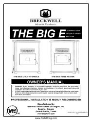
FREEST<strong>AND</strong>ING<br />
<strong>AND</strong> INSERT<br />
PELLET FIRED<br />
STOVES<br />
RETAIN THESE<br />
INSTRUCTIONS<br />
FOR FUTURE<br />
REFERENCE<br />
<strong>INSTALLATION</strong> <strong>AND</strong> <strong>OPERATION</strong><br />
<strong>MANUAL</strong><br />
Freestanding Model<br />
Advantage II-T C INS<br />
These appliances must be properly installed and operated in order<br />
to prevent the possibility of a house fire. Please read this entire<br />
owner's manual before installing and using your pellet stove. Failure<br />
to follow these instructions could result in property damage,<br />
bodily injury or even death. Contact your local building or fire officials<br />
to obtain a permit and information on any installation requirements<br />
and inspection requirements in your area.<br />
www.<strong>Pellet</strong>King.com<br />
Freestanding Model<br />
Advantage II-T C FS<br />
P/N 775096M, Rev. E, 11/03
IMPORTANT WARNINGS<br />
CAUTION: Read this manual thoroughly before starting installation. For your safety, follow the installation, operation<br />
and maintenance instructions exactly without deviation. Failure to follow these instructions may result<br />
in a possible fire hazard and will void the warranty. If this appliance is not properly installed, a house fire may<br />
result. Contact local building or fire officials about requirements and installation inspection in your area.<br />
1. DO NOT CONNECT THIS UNIT TO A CHIMNEY<br />
FLUE CONNECTED TO ANOTHER APPLIANCE.<br />
2. Do not connect this appliance to air ducts or any<br />
air distribution system.<br />
3. Do not install a flue damper in the exhaust venting<br />
system of this appliance.<br />
4. Do not use class B venting intended for gas appliances<br />
as a chimney or connector pipe on a pellet<br />
fired appliance.<br />
5. The minimum clearances must be maintained for<br />
all combustible surfaces and materials including;<br />
furniture, carpet, drapes, clothing, wood, papers,<br />
etc. Do not store firewood within this clearance<br />
space.<br />
6. <strong>INSTALLATION</strong> DISCLAIMER - This stoves exhaust<br />
system works with negative combustion chamber<br />
pressure and a slightly positive chimney pressure.<br />
Therefore, it is imperative that the exhaust system<br />
be gas tight (air tight, sealed connection) and installed<br />
correctly. Since Lennox Hearth Products<br />
has no control over the installation of your stove,<br />
Lennox Hearth Products grants no warranty, implied<br />
or stated for the installation or maintenance<br />
of your stove, and assumes no responsibility for<br />
any consequential damage(s).<br />
7. Burning any kind of fuel consumes oxygen. If outside<br />
air is not ducted to the appliance, ensure that<br />
there is an adequate source of fresh air available to<br />
the room where the appliance is installed.<br />
8. The stove will not operate using natural draft, nor<br />
without a power source for the blower and fuel<br />
feeding systems.<br />
9. Never use gasoline, gasoline-type lantern fuel,<br />
kerosene, charcoal lighter fluid, or similar liquids<br />
to start or "freshen up" a fire in this heater. Keep<br />
all such liquids well away from the heater while it is<br />
in use.<br />
10. CONTINUOUS <strong>OPERATION</strong>: When operated correctly,<br />
this appliance cannot be overfired. Continuous<br />
operation at a maximum burn can, however,<br />
shorten the life of the electrical components<br />
(blowers, motors, and electronic controls), and is<br />
not recommended. Typical approved operation<br />
would include running at the low to mid range setting<br />
with occasional running on the maximum setting<br />
during the coldest periods of the winter. The<br />
room air blower speed control should be turned to<br />
high when operating the stove on the high heat<br />
setting.<br />
11. CAUTION: NEVER PUT FINGERS NEAR AUGER.<br />
<strong>Pellet</strong> fuel is fed to the UltraGrate TM by a screw auger.<br />
This auger is driven by a high torque motor.<br />
PAGE 2<br />
www.<strong>Pellet</strong>King.com<br />
The auger is capable of doing serious harm to fingers.<br />
Keep pellets in the hopper at all times and<br />
keep fingers away from auger. The auger can start<br />
and stop automatically at any time while the stove<br />
is running.<br />
12. CAUTION: HOT WHILE IN <strong>OPERATION</strong>. An appliance<br />
hot enough to warm your home can severely<br />
burn anyone touching it. Keep children, clothing<br />
and furniture away. Contact may cause skin burns.<br />
Do not let children touch the appliance. Train them<br />
to stay a safe distance from the unit.<br />
13. APPROVED FUEL: This appliance is designed specifically<br />
for use only with pelletized wood fuels<br />
only. With its advanced UltraGrate TM technology,<br />
this appliance is designed and approved for the<br />
burning of wood residue pellets with up to 3% ash<br />
content. This appliance is NOT approved to burn<br />
cardboard, nut hulls, cherry pits, corn, etc. regardless<br />
if it is in pellet form. Failure to comply with this<br />
restriction will void all warranties and the safety<br />
listing of the stove. Consult with your authorized<br />
Lennox Hearth Products dealer for approved pellet<br />
fuels.<br />
14. FLY ASH BUILD-UP: For all wood pellet fuelburning<br />
heaters, the combustion gases will contain<br />
small particles of fly ash. This will vary due to the<br />
ash content of the fuel being burned. Over time,<br />
the fly ash will collect in the exhaust venting system<br />
and restrict the flow of the flue gases. The exhaust<br />
venting system should be inspected regularly<br />
and cleaned as necessary.<br />
15. SOOT FORMATION: Incomplete combustion can<br />
occur during startup, shutdown, or incorrect operation<br />
of the room heater. This can lead to some<br />
soot collecting in the exhaust venting system. A<br />
precautionary inspection on a regular basis is advisable<br />
to determine the necessity of cleaning. The<br />
exhaust venting system should be inspected regularly<br />
and cleaned as necessary.<br />
16. DISPOSING OF ASHES: Any ashes removed from<br />
the pellet stove must be deposited in a metal container<br />
with a tight-fitting lid. The closed container<br />
of ashes should be placed on a noncombustible<br />
floor or on the ground, well away from all combustible<br />
materials, outside of the dwelling pending final<br />
disposal. If the ashes are disposed of by burial<br />
in soil or otherwise locally dispersed, they should<br />
be retained in the closed container until all cinders<br />
have been thoroughly cooled.<br />
17. SAVE THESE INSTRUCTIONS.<br />
18. See the listing label located in the hopper (or see<br />
Safety / Listing Labels on page 43).
TABLE OF CONTENTS<br />
Important Warnings ................................................ 2<br />
Testing / Listing, EPA, Using this Manual................ 3<br />
Planning Your Installation ..................................... 4-8<br />
Manufactured (Mobile) Home Installation ................8<br />
Installation .......................................................... 9-20<br />
Care and Operation .......................................... 21-25<br />
Routine Maintenance........................................ 26-30<br />
Specifications.................................................... 31-32<br />
Definitions ...............................................................33<br />
Wiring Diagram .......................................................34<br />
Troubleshooting ................................................ 35-37<br />
Replacement Parts List / Diagrams .................. 38-41<br />
Optional Accessories ..............................................42<br />
Safety / Listing Label...............................................43<br />
EPA and Colorado Compliance Label ....................44<br />
Simple Operating Instructions Label.......................45<br />
Installation Tips Label .............................................46<br />
Ownership Records ................................................47<br />
LISTING / TESTING<br />
Listing: The listing laboratory is ITS (Intertek Testing<br />
Services) and the listing mark is Warnock Hersey.<br />
Testing: In accordance with the specifications and procedures<br />
listed in UL 1482 / ULC S627 / CSA B366.2M / ULC<br />
S628 & ASTM E1509 for solid fuel room heater, report #<br />
5515, 12-91and ASTM E1509 Report # 476-1244, 3-96.<br />
This appliance has been independently tested to UL, ULC<br />
and CSA standards. UL 1482 & ULC S627 states requirements<br />
for installations as a freestanding room heater,<br />
or hearth insert for masonry fireplaces listed to UBC 37 or<br />
ULC S628, or factory built (zero clearance) fireplaces<br />
listed to UL 127 or ULC S610.The safety-listing label is<br />
located on an inside hopper surface of the pellet stove.<br />
Please read this safety label carefully. It contains important<br />
information about installation and operation of this<br />
appliance. This appliance is tested and listed for residential<br />
installation according to current national and local<br />
building codes as:<br />
• A Freestanding Room Heater –FS<br />
• A Insert Room Heater – INS<br />
• A Manufactured (mobile) Home Heater – FS & INS<br />
EPA (Environmental Protection Agency)<br />
Status: EPA – Certified to comply with July 1990 particulate<br />
emission standards.<br />
PRODUCT IS SUBJECT TO CHANGE WITHOUT NO-<br />
TICE.<br />
CONGRATULATIONS ON THE PURCHASE OF YOUR<br />
NEW PELLET STOVE MANUFACTURED BY LENNOX<br />
HEARTH PRODUCTS.<br />
When you purchased your new pellet stove, you joined<br />
the ranks of thousands of concerned individuals<br />
whose answer to their home heating needs reflects<br />
their concern for aesthetics, efficiency and our environment.<br />
We extend our continued support to help you<br />
achieve the maximum benefit and enjoyment available<br />
from your new pellet stove.<br />
It is our goal at Lennox Hearth Products to provide<br />
you, our valued customer, with an appliance that will<br />
ensure you years of trouble free warmth and pleasure.<br />
Thank you for selecting a Lennox Hearth Products<br />
stove as the answer to your home heating needs.<br />
Sincerely,<br />
All of us at Lennox Hearth Products<br />
PAGE 3<br />
www.<strong>Pellet</strong>King.com<br />
PACKAGING LIST<br />
The assembled pellet stove model Advantage II-T C FS and<br />
Advantage II-T C INS are packaged with an accessory package,<br />
which contains the following:<br />
One - Installation and operation instructions manual.<br />
One - Warranty.<br />
One - EPA Label.<br />
One - Colorado compliance certificate<br />
One - Power cord.<br />
One - Damper hex wrench<br />
One - Grate scraper/tool.<br />
One - Wall thermostat.<br />
One - Roll of thermostat wire.<br />
Two - Leveling bolts, 3/8"-16 x 3 1/2” (Insert only)<br />
One - Ash pan trim cover<br />
One - Trivet<br />
One - Control board (Insert)<br />
One - Video tape<br />
One - Fireplace warning label (insert only)<br />
One - Damper rod assembly with tag<br />
Surround Kit (For Advantage II-T C INS Only)<br />
(Purchased separately, see page 42) kit is packaged with:<br />
One - Top surround panel.<br />
One - Left surround panel.<br />
One - Right surround panel with door.<br />
Pedestal Kit (For Advantage II-T C FS Only)<br />
(Included with freestanding stove) kit is packaged with:<br />
One - Pedestal assembly.<br />
Three -Bolts, 3/8" x 1/2”.<br />
Three -Washers.<br />
USING THIS <strong>MANUAL</strong><br />
Please read and carefully follow all of the instructions<br />
found in this manual. Please pay special attention to the<br />
safety instructions provided in this manual. The homeowner’s<br />
Care and Operation Instructions included here will<br />
assure you have many years of dependable and enjoyable<br />
service from your appliance.
PLANNING YOUR <strong>INSTALLATION</strong><br />
QUESTIONS TO ASK LOCAL BUILDING OFFICIAL<br />
A correct installation is critical and imperative for reducing<br />
fire hazards and perilous conditions that can arise<br />
when wood pellet burning appliances are improperly<br />
installed. The installer must follow all of the manufacturers’<br />
instructions.<br />
The installation of this appliance must conform to local<br />
codes and applicable state and federal requirements.<br />
Familiarity with these requirements before installation is<br />
essential. Important considerations to discuss with local<br />
building officials include:<br />
1. Applicable codes (i.e. Uniform Mechanical Code,<br />
State or Regional Codes).<br />
Electrical codes:<br />
In USA, NEC, ANSI / NFPA 70 – Latest Edition<br />
In Canada, CSA C22.1 – Latest Edition<br />
Power Supply Requirements – The power cord must<br />
be plugged into a standard, 115 volt, 60 Hz grounded<br />
electrical outlet. The approximate power requirement is<br />
362 Watts, and will peak up to 736 Watts for approximately<br />
6 minutes when the self-igniter is operating (it<br />
will turn off 2 minutes after flame detection). The power<br />
cord must be routed to avoid contact with any of the hot<br />
or sharp exterior surface areas of the stove. When installed<br />
into a manufactured (mobile) home, the appliance<br />
must be electrically grounded to the steel chassis<br />
(see page 8, Manufactured [Mobile] Home Requirements).<br />
These requirements must be met unless otherwise<br />
specified by state or local authorities.<br />
WARNING - ELECTRICAL GROUNDING IN-<br />
STRUCTIONS: THIS APPLIANCE IS EQUIPPED<br />
WITH A THREE-PRONG (GROUNDING) PLUG<br />
FOR YOUR PROTECTION AGAINST SHOCK<br />
HAZARD <strong>AND</strong> SHOULD BE PLUGGED DI-<br />
RECTLY INTO A PROPERLY GROUNDED<br />
THREE-PRONG RECEPTACLE. DO NOT CUT<br />
OR REMOVE THE GROUNDING PRONG FROM<br />
THIS PLUG. DO NOT ROUTE POWER CORD<br />
UNDER OR IN FRONT OF APPLIANCE.<br />
2. Local amendments?<br />
3. Is a permit required - cost?<br />
You may wish to contact your insurance company<br />
to ask if they require this.<br />
4. Is outside combustion air required?<br />
5. Rooms where the installation is not allowed?<br />
PAGE 4<br />
www.<strong>Pellet</strong>King.com<br />
<strong>INSTALLATION</strong> / MAINTENANCE ST<strong>AND</strong>ARDS<br />
National Fire Protection Association – The primary<br />
NFPA standard that refers to installation and maintenance<br />
of pellet appliances and venting is NFPA 211 –<br />
Latest Edition: Chimneys, Fireplaces, Vents, and Solid<br />
Fuel appliances.<br />
SELECTING A LOCATION<br />
The design of your home and where you place your<br />
stove will determine its value as a source of heat. A pellet<br />
stove depends primarily on air circulation (convection)<br />
to disperse its heat, and therefore, a central location<br />
is often best. There are other practical considerations,<br />
which must be considered before a final selection<br />
of locations is made.<br />
♦ Existing Chimneys<br />
♦ <strong>Pellet</strong> Fuel Storage<br />
♦ Aesthetic Considerations<br />
♦ Roof Design (rafter locations & roof pitch)<br />
♦ Room Traffic<br />
♦ Proximity to Combustibles<br />
♦ Electrical Wiring<br />
The installation of this stove will require some research.<br />
Once your options are determined, consult with your<br />
local building department who will be able to give you<br />
the necessary installation requirements for your area (Is<br />
a building permit required? Rooms where installation<br />
may not be allowed, etc.).<br />
WARNING: CHECK ALL LOCAL BUILDING <strong>AND</strong><br />
SAFETY CODES BEFORE <strong>INSTALLATION</strong>. THE IN-<br />
STALLATION INSTRUCTIONS <strong>AND</strong> APPROPRIATE<br />
CODE REQUIREMENTS MUST BE FOLLOWED EX-<br />
ACTLY <strong>AND</strong> WITHOUT COMPROMISE. ALTERA-<br />
TIONS TO THE STOVE ARE NOT ALLOWED. DO<br />
NOT CONNECT THE STOVE TO A CHIMNEY SYS-<br />
TEM SERVING ANOTHER STOVE, APPLIANCE, OR<br />
ANY AIR DISTRIBUTION DUCT. FAILURE TO FOL-<br />
LOW THESE INSTRUCTIONS WILL VOID THE<br />
MANUFACTURERS WARRANTY.<br />
SMOKE DETECTORS<br />
Since there are always several potential sources of fire<br />
in any home, we recommend installing smoke detectors.<br />
If possible, install the smoke detector in a hallway<br />
adjacent to the room (to reduce the possibility of occasional<br />
false activation from the heat produced by the<br />
stove). If your local code requires a smoke detector be<br />
installed within the same room, you must follow the requirements<br />
of your local code. Check with your local<br />
building department for requirements in your area.
PLANNING YOUR <strong>INSTALLATION</strong><br />
FLOOR PROTECTION – Advantage II-T C FS<br />
(For USA and Canada)<br />
This appliance<br />
requires 3/8" (10<br />
mm) minimum noncombustible<br />
floor<br />
protection designed<br />
for solid fuel burning<br />
appliances having a<br />
thermal conductivity<br />
of k = .84 BTU in/ft<br />
or equivalent. If the<br />
floor protection is to<br />
be stone, tile, brick,<br />
etc., it must be mortared<br />
or grouted to<br />
form a continuous<br />
non-combustible sur-<br />
face (See Using Alternate Material As Floor Protector below).<br />
If a chimney connector extends horizontally over the floor,<br />
protection must cover the floor under the connector and at<br />
least 2" (51 mm) to either side. The floor protector must fully<br />
cover the area beneath the appliance and extend 6” to the<br />
front, 6” to the sides, and up to 6” from the back (see illustration<br />
above and following note).<br />
*Note: When installed at clearances less than 6”, the floor<br />
protection is only required to extend to the wall.<br />
FLOOR PROTECTION / HEARTH EXTENSION USING AL-<br />
TERNATE MATERIAL AS FLOOR PROTECTOR (also see<br />
Floor Protection above for freestanding models and Hearth<br />
Requirements, page 8 for the insert model)<br />
The hearth pad or alternate material used as a floor/hearth<br />
protector must be constructed of a durable noncombustible<br />
material having an equal or better thermal conductivity value<br />
(lower k value) of k = .84 BTU / IN FT 2 HR °F or a thermal<br />
resistance that equals or exceeds r = 1.19 HR °F FT 2 IN/BTU<br />
with a minimum thickness of 3/8”. With these values, determine<br />
the minimum thickness of the alternate material required using<br />
the formula(s) and the table shown here (see chart - Approved<br />
Alternate Materials for Floor/Hearth Protection).<br />
Note: Any noncombustible material having a minimum thickness<br />
of 3/8” (10 mm) whose k value is less than .84 or whose r value is<br />
more than 1.19 is acceptable. If the alternate material used has a<br />
higher k value or lower r value will require a greater thickness of<br />
the material used. In some cases, if the k value is less or the r<br />
value higher, a thinner material may be used.<br />
Methods of determining floor protection equivalents:<br />
To determine the thickness required for the alternate material<br />
when either the k value or r value is known, use either the k<br />
formula or r formula:<br />
Example: Durock Cement is to be used for the floor protection.<br />
How thick must this material be? The following formulas<br />
give the means of determining minimum thickness required.<br />
TM = minimum thickness required for alternate material<br />
kM = k value per inch of alternate material<br />
TL = minimum thickness of listed material<br />
rM = r value per inch of alternate material<br />
Using the k formula:<br />
6”<br />
(153mm)<br />
min.<br />
Top View<br />
6”<br />
153 mm<br />
6”<br />
153 mm<br />
6”<br />
(153mm)<br />
min.<br />
Minimum k-value (per Inch) Specified min.<br />
thickness of = of alternate material x thickness<br />
alternate k-value (per inch) of listed<br />
material of listed material material<br />
PAGE 5<br />
TM (inches) = kM x TL<br />
.84<br />
TM (inches) = 1.92 x .375 (3/8”)<br />
.84<br />
Answer using k: 2.29 x 0.375” = 0.858 = ~7/8”<br />
7/8” thickness (minimum) Durock Cement will be required.<br />
Using the r formula:<br />
TM (inches) = 1.19 x TL<br />
rM<br />
TM (inches) = 1.19 x 375 (3/8”)<br />
.52<br />
Answer using r: 2.29 x 0. 375” = 0.858 = ~7/8”<br />
7/8” thickness (minimum) Durock Cement will be required.<br />
At times it is important to know what combination of materials are<br />
acceptable for use as floor protection. The “R values” are used to<br />
determine acceptable combinations of materials because “R values”<br />
are additive where r and k values are not.<br />
“R value” = 1 = r x thickness of material used<br />
k<br />
Example: Given that the required “R value” for a suitable floor protector<br />
used must be equal to or greater than “R” = r x TL = 1.19 x<br />
.375” = .45.<br />
Listed Material<br />
Thermal Values Specified<br />
Minimum<br />
Thickness<br />
k (per inch) r (per inch) TL<br />
Listed Material → .84 1.19 3/8” (.375)<br />
Alternative<br />
Materials ↓<br />
Approved Alternate Materials for<br />
Floor/Hearth Protection (**)<br />
Thermal Values * Minimum<br />
Thickness<br />
k (per inch) r (per inch) TM<br />
Kaowool M Board .47 2.13 * 3/8”<br />
Micore 160 .35 2.86 * 3/8”<br />
Micore 300 .46 2.18 * 3/8”<br />
Durock Cement 1.92 .52 7/8”<br />
Hardibacker 1.95 .51 7/8”<br />
Hardibacker 500 2.30 .44 1 1/8”<br />
Cultered Stone<br />
Hearthstone<br />
2.82 .35 1 5/8”<br />
Wonderboard 3.23 0.31 1 1/2”<br />
Face brick 9.00 0.11 4 1/8”<br />
Common brick 5.00 0.20 2 1/4”<br />
Cement mortar 5.00 0.20 2 1/4”<br />
Ceramic tile 12.5 .08 5 5/8”<br />
Marble ~20.0 ~.05 9”<br />
Note: To convert inches to millimeters divide by .03937.<br />
* After minimum thickness is calculated, the thickness can be no<br />
less than 3/8” (.375” / 10mm).<br />
(**) If the floor protector to be used is a noncombustible material and is<br />
NOT listed on the chart above, the manufacturer of the material must<br />
provide either the listed k-value per inch or r-value per inch and the<br />
minimum acceptable thickness will need to be calculated per instructions<br />
on this page.<br />
www.<strong>Pellet</strong>King.com
PLANNING YOUR <strong>INSTALLATION</strong><br />
Clearances to combustibles are determined from testing to applicable standards for allowable<br />
heat transfer. The clearances allowed as shown here, do not take into account operation<br />
or serviceability requirements.<br />
CLEARANCES<br />
Advantage II-T C FS - Standard residential or manufactured<br />
(mobile) home installation. These appliances require<br />
the following minimum clearances to combustibles:<br />
MINIMUM CLEARANCES TO COMBUSTIBLES<br />
Advantage II-T C<br />
FS<br />
▪ Clearance to<br />
Combustibles<br />
Manufactured (Mobile) Home<br />
or Residential Installation<br />
Horizontal Flue – Di- Interior Vertical Flue<br />
rectly Through Wall<br />
inch / millimeter inch / millimeter<br />
A - Sidewall to unit ♦6” / 153 mm ♦6” / 153 mm<br />
B – Backwall to unit *2” / 50 mm 9” / 230 mm<br />
C – Sidewall to unit<br />
Corner<br />
*2” / 50 mm *2” / 50 mm<br />
D - Alcove to Fuel<br />
Hopper<br />
6” / 150 mm 6” / 150 mm<br />
E – Max. Depth of<br />
Alcove<br />
•16” / 406 mm •16” / 406 mm<br />
F – Flue to Wall n / a 3” / 77 mm<br />
♦ Measured to fuel hopper<br />
• Alcove Requirements – Minimum Height 50” / 127 cm<br />
Minimum Width 36” / 966 mm<br />
Maximum. Depth 16" / 406 mm<br />
� Minimum clearances specified may not allow for<br />
ease of operation and maintenance (please take<br />
this in to account when planning the installation).<br />
If installed to the minimum clearances, removal of<br />
the appliance may be necessary for servicing.<br />
• Recommended clearance zone from the front of<br />
the appliance to combustibles is 4 feet minimum.<br />
* The certified back wall clearance as shown on the<br />
listing label is 1" (see Safety / Listing Label) but for<br />
proper hopper lid operation in corner and parallel<br />
installations a 2" clearance is required.<br />
PAGE 6<br />
www.<strong>Pellet</strong>King.com<br />
E<br />
Alcove - Advantage II-T C FS<br />
Parallel Wall - Advantage II-T C FS<br />
F<br />
*B<br />
Corner - Advantage II-T C FS<br />
F<br />
C<br />
F<br />
*B<br />
D D<br />
C<br />
A
PLANNING YOUR <strong>INSTALLATION</strong><br />
MASONRY <strong>AND</strong> FACTORY BUILT FIREPLACES<br />
The model Advantage II-T C INS is approved for installation<br />
into a solid fuel burning fireplace, either a masonry<br />
fireplace (built to UBC 37 or ULC S628 standards) or an<br />
approved factory-built / zero clearance fireplace (built to<br />
UL 127 or ULC S610 standards). (see pages 19 through<br />
20 for additional information on venting).<br />
Dimensions Into a Fireplace<br />
Height 20 1/4” / 515 mm<br />
Width 30 1/4” / 768 mm<br />
Depth w/Tee 18 3/8” / 467 mm<br />
Depth–DV thru Masonry Wall 12 1/2” / 318 mm<br />
Recommended clearance zone from the front of the appliance<br />
to combustibles is 4 feet minimum.<br />
CAUTION: The fireplace in which the Advantage II-T C<br />
INS is to be installed must be thoroughly cleaned if it<br />
has been used to burn wood or synthetic logs. Have the<br />
chimney and all inside surfaces of the fireplace brushed<br />
and vacuumed so that no soot, embers, or loose combustion<br />
deposits can be drawn into the heat circulation<br />
blower and blown into the living area. If any portion of<br />
the chimney system shows signs of structural or mechanical<br />
weaknesses, such as: cracks, leaky joints, corroded<br />
or warped surfaces, the faulty portion must be<br />
repaired or replaced prior to installing this appliance.<br />
IMPORTANT: When installing model Advantage II-T C<br />
INS into a factory built fireplace or heatform, the air flow<br />
within and around the fireplace shall not be altered by the<br />
installation of the insert (i.e. DO NOT BLOCK louvers or<br />
cooling air inlet or outlet ports, circulating air chambers in<br />
a steel fireplace liner or metal heat circulator). The factory<br />
built firebox must accept the insert without modification<br />
other than removing bolted or screwed together pieces<br />
such as smoke shelf / deflectors, ash lips, screen or door<br />
tracks and damper assemblies. Any fireplace component,<br />
which is removed, must be retained so they can be reinstalled<br />
to restore the fireplace to its original operating condition.<br />
The removal of any part must not alter the integrity<br />
of the outer shell of the pre-engineered fireplace cabinet<br />
in any way. A Warning Label (provided with appliance)<br />
must be installed in the fireplace firebox so that it shall be<br />
visible upon removal of the fireplace insert (see Fireplace<br />
Warning Label, below). Use RTV high Temperature Silicone<br />
as an adhesive to affix the warning label.<br />
Fireplace Warning Label<br />
Provided in accessory package (insert only)<br />
THIS FIREPLACE HAS BEEN ALTERED TO AC-<br />
COMMODATE A FIREPLACE INSERT <strong>AND</strong> SHOULD<br />
BE INSPECTED BY A QUALIFIED PERSON PRIOR<br />
TO RE-USE AS A CONVENTIONAL FIREPLACE.<br />
PAGE 7<br />
www.<strong>Pellet</strong>King.com<br />
HEARTH / FLOOR PROTECTION - Advantage II-T C<br />
INS<br />
In the USA and Canada, the area below and directly in<br />
front of the Advantage II-T C INS must be an approved<br />
fireplace hearth or protected by a non-combustible<br />
hearth / floor protector with a minimum thickness of 3/8”<br />
which has a thermal conductivity of k (per inch) = .84 or<br />
lower value (better thermal protection) or resistance of r<br />
(per inch) = 1.19 or higher value. See Floor Protection /<br />
Hearth Extension Using Alternate Material as Floor Protector<br />
on page 5 which explains minimum thermal protection<br />
requirements.<br />
The protected area must extend 6” to the front of the face<br />
of the Advantage II-T C INS.<br />
MINIMUM CLEARANCES TO COMBUSTIBLES<br />
Masonry and Factory Built Fireplaces<br />
inches / millimeters<br />
A - Insert to side wall 6 “ / 150 mm<br />
B - Insert to side trim 1” / 25 mm<br />
C - Hearth extension 6” / 150 mm<br />
D - Insert to mantel 18” / 457 mm<br />
E - Insert to top trim 1” / 25 mm<br />
D<br />
C<br />
Front View<br />
D E<br />
A<br />
E<br />
Side View<br />
B
PLANNING YOUR <strong>INSTALLATION</strong><br />
MANUFACTURED (MOBILE) HOME INSTAL-<br />
LATION<br />
Freestanding Model – Advantage II-T C FS<br />
In addition to the standard installation instructions,<br />
the following instructions may be required by local,<br />
state or federal building codes:<br />
• Stove must be permanently bolted to the floor.<br />
• An outside air inlet must be provided for combustion<br />
and be unrestricted while unit is in use.<br />
Use a galvanized or stainless steel pipe for the<br />
duct (the outside air inlet on the stove is 1 5/8"<br />
diameter).<br />
• Stove must be permanently electrically<br />
grounded to the steel chassis of the home. The<br />
location selected for ground attachment to the<br />
stove must be dedicated for this purpose.<br />
• See pages 13 through 18 for additional information<br />
on venting requirements.<br />
• Do not install appliance in a sleeping room.<br />
• The structural integrity of the manufactured<br />
home floor, walls, ceiling and roof must be<br />
maintained.<br />
NOTE: The grounding of this product, at installation,<br />
must comply with NFPA-70 standards,<br />
CSA C22.1 in Canada, as well as<br />
any local codes.<br />
24 ¾”<br />
Model – Advantage II-T C FS<br />
Pedestal Air Inlet<br />
25”<br />
12 ½”<br />
Outside Air Inlet<br />
1 5/8" diameter<br />
6 7/8”<br />
MANUFACTURED (MOBILE) HOME EXHAUST VENT PIPE<br />
<strong>INSTALLATION</strong> GUIDELINES<br />
Use only “PL” pellet vent pipe listed to UL 641 and ULC<br />
S609. The pipe should extend at least 3 feet above the part<br />
of the roof through which it passes. The top of the pipe<br />
should be at least 2 feet above the highest required elevation<br />
of any part of the manufactured (mobile) home within 10 feet<br />
of the pipe (see page 14, Manufactured [Mobile] Home<br />
Chimney Height Requirements).<br />
If the exhaust vent exits the manufactured (mobile) home at a<br />
location other than the roof, and exits at a point 7 feet or less<br />
above the ground level on which the manufactured (mobile)<br />
home is position a guard or method of enclosing the pipe<br />
shall be provided at the point of exit for a height of up to 7<br />
feet. The openings, if any, in this guard shall not allow a 3/4”<br />
rod to pass through. A 1/2” rod could pass through but should<br />
not be able to touch the pipe when inserted through the opening<br />
a distance of 4 inches.<br />
Bolt<br />
PAGE 8<br />
www.<strong>Pellet</strong>King.com<br />
Bolt<br />
Floor Protector<br />
Floor<br />
Steel Chassis<br />
Ground<br />
To Chassis
<strong>INSTALLATION</strong><br />
REMOVING APPLIANCE FROM PALLET<br />
1. After removing the packaging from the stove, lift the<br />
hopper lid, and remove all pre-packaged items that<br />
were shipped in the hopper. Next, open the stove<br />
door and remove all pre-packaged items.<br />
2. Using a 9/16” socket or open end wrench, remove<br />
the bolts which secure stove to pallet. The bolts are<br />
located on the underside of the wooden pallet.<br />
Underside of Pallet<br />
Remove the two bolts from underneath the pallet.<br />
NOTE: Bolts may be used in manufactured (mobile)<br />
home installation to permanently secure stove to floor<br />
(see previous page).<br />
PAGE 9<br />
www.<strong>Pellet</strong>King.com<br />
ASH PAN COVER ASSEMBLY<br />
Remove the ash pan cover trim from hopper. Remove<br />
polyfoam wrapping and press into place as shown in illustration<br />
below. The ash pan cover trim has two magnets<br />
attached which will secure it in place.<br />
Ash Pan Cover<br />
INSTALLING PEDESTAL TO BODY<br />
If your stove is a freestanding model, secure the pedestal<br />
to the stove body as follows:<br />
1. Remove the pedestal from the box and place it beside<br />
the stove body.<br />
2. Lift the stove onto the pedestal base.<br />
3. Install the three bolts and washers provided through<br />
the holes in the mounting flange of the pedestal and<br />
into the threaded pressed nuts in the stove bottom.<br />
4. Tighten the fasteners using a socket or wrench.<br />
Pedestal – Top View<br />
Install<br />
three bolts<br />
Attach stove to pedestal by inserting three bolts<br />
(provided with pedestal kit)
<strong>INSTALLATION</strong><br />
<strong>INSTALLATION</strong> CHECK LIST<br />
It is strongly recommended that you have an authorized<br />
Lennox Hearth Products dealer install your stove. If you<br />
install your stove yourself, you should review your installation<br />
plan with an authorized Lennox Hearth Products<br />
dealer. Improper installation may void your warranty.<br />
Check list:<br />
Check off each item as you proceed with the installation<br />
process.<br />
� Read the ENTIRE stove installation section first<br />
� Read the Insert or Freestanding section (whichever<br />
applies).<br />
� Determine the appropriate measurements and locations<br />
for your installation.<br />
� Follow the general installation directions under Stove<br />
Installation and the installation section appropriate to<br />
your stove.<br />
� Be sure to pre-fit all items before you install, fasten,<br />
or set up the stove permanently.<br />
PAGE 10<br />
www.<strong>Pellet</strong>King.com<br />
Prior to lighting your stove:<br />
� Review the Important Warnings section (page 2).<br />
� Review Fuel Specifications (page 25).<br />
� Review and follow instructions in the Care and Operation<br />
Section (pages 21 to 25).<br />
� Plug power cord connector into corresponding connector<br />
on the back of appliance (see illustrations on<br />
page 12 showing connector locations).<br />
Note: Advantage II-T C INS – Route power cord behind<br />
side surround panel.<br />
After you have begun operation of your stove:<br />
� Review the routine cleaning / maintenance information.<br />
� Enjoy the warmth from your new Lennox Hearth<br />
Products pellet stove!<br />
Advantage II-T C Insert<br />
It is important to level the appliance. In some installations<br />
such as a recessed firebox floor (if the existing fireplace<br />
floor is lower than the hearth), install the 2 leveling<br />
bolts (3/8-16 x 3 1/2” long) into the 2 threaded holes at<br />
the rear base of the Advantage II-T C INS. Adjust bolts<br />
until appliance is level.
<strong>INSTALLATION</strong><br />
INSTALLING SURROUND ASSEMBLY - Advantage II-T<br />
C INS (to be done after venting system is installed)<br />
The surround kit (purchased separately) comes with a set<br />
of metal panels that enclose the fireplace opening when<br />
fitted together. Put the surround assembly together according<br />
to the following instructions (ref. see illustration below).<br />
1. Remove panels from package.<br />
2. Verify that you have all three panels and a package with<br />
“pop” rivets and #8 self-tapping screws. If you do not have<br />
a “pop” rivet tool, you should arrange to buy or borrow one<br />
for this installation.<br />
3. Set the stove on the hearth so that the rear of the stove is<br />
accessible to complete all pipe connections.<br />
4. Verify that the hopper cover is all the way to the front and<br />
open as high as your fireplace opening will allow. Secure<br />
the hopper cover with at least two #8 screws on all three<br />
sides. Tip: Spreading the side panels slightly may be necessary<br />
to complete this step.<br />
5. Place four rivets and your “pop” rivet tool beside the stove<br />
and line up the right side panel (with control door) with the<br />
holes in the side of the stove. (When the side panel is<br />
properly installed, the hinge flange will be to the rear of the<br />
stove.) Attach the panel to the stove with four “pop” rivets.<br />
6. Secure the left side surround panel to the stove using the<br />
procedure described in step #5.<br />
7. Before proceeding further, check pipe connections to ensure<br />
that all joints are sealed with high-temperature RTV<br />
silicone and properly secured. Refer to detailed venting instructions<br />
on pages 16, 19 and 20.<br />
8. The stove may now be pushed into the fireplace cavity to<br />
within 1 1/2” of the face of the fireplace.<br />
9. Set the top surround panel in place over the two side panels.<br />
Carefully slide the panel downward into the “U” clips<br />
Optional Trim<br />
Top Surround Panel<br />
Left Hinged<br />
Surround Panel<br />
PAGE 11<br />
attached to the back of the Advantage II-T C INS. Tip: Be<br />
careful to align the notched cutouts in the top surround<br />
panel with the stove side panels. Adjust side to side if necessary<br />
to align with the surround side panels.<br />
10. Unwrap the control board carefully without touching<br />
any electrical components. Holding the sides of the<br />
control board, lower the bottom edge into the slot in<br />
the bottom of the control door opening Install the<br />
control board onto the right side panel (with door) using<br />
the #8 hex head screw provided.<br />
11. Connect the wiring harness from the Advantage II-T C INS<br />
into corresponding connector on control board.<br />
12. Check the Advantage II-T C INS placement in the<br />
fireplace. To reposition, open the door and make any<br />
needed adjustment by pulling forward and then pushing<br />
sideways. Once the unit has been centered to<br />
your satisfaction, close the door and push the Advantage<br />
II-T C INS back into place so the surround is<br />
flush with the face of the hearth. Tip: Before completing<br />
this step, verify that the control board will not<br />
hit the edge of the fireplace opening.<br />
If using the optional gold surround trim, remove the trim<br />
from its packaging and place the piece with the two mitered<br />
ends along the top panel. Place the two remaining<br />
side pieces on the surround so that the mitered ends<br />
align. Cut the non-mitered ends of the shroud trim with<br />
scissors, if necessary.<br />
In factory built and masonry fireplaces, a means<br />
must be provided to prevent room air passage to the<br />
chimney cavity of the fireplace. This may be accomplished<br />
by sealing the damper area around the chimney<br />
liner or pipe.<br />
Right Hinged<br />
Surround Panel<br />
www.<strong>Pellet</strong>King.com<br />
Optional Trim
<strong>INSTALLATION</strong><br />
THERMOSTAT <strong>INSTALLATION</strong>:<br />
NOTE: Always Disconnect Power Before Performing<br />
The Thermostat Installation.<br />
A 24 volt wall thermostat and 20 feet of 18-gage thermostat<br />
wire is included in your stove’s accessory package.<br />
It is recommended that the thermostat and thermostat<br />
wire be installed by an authorized Lennox Hearth Products<br />
dealer.<br />
Installation Steps:<br />
1. Unplug stove power cord from the wall outlet.<br />
2. Locate the thermostat terminal block on the back of<br />
the stove.<br />
3. Loosen the two terminal screws on the terminal block<br />
and remove jumper.<br />
4. Connect the two wires from your thermostat to the<br />
terminals (one per terminal). Ensure that the purple<br />
wires from the harness remain connected to the terminal<br />
block and tighten the terminal screws. Make<br />
sure the wires are firmly connected to the thermostat.<br />
5. Plug in the stove and you are ready to operate with<br />
your thermostat!<br />
IMPORTANT: IF THE WALL THERMOSTAT PRO-<br />
VIDED IS NOT USED, THE JUMPER IS REQUIRED<br />
FOR THE STOVE TO OPERATE<br />
PAGE 12<br />
www.<strong>Pellet</strong>King.com<br />
Rear View of Advantage II-T C FS<br />
Back of Stove<br />
Thermostat<br />
Terminal<br />
Block<br />
Thermostat Jumper
<strong>INSTALLATION</strong><br />
VENTING REQUIREMENTS<br />
It is recommended that only an authorized dealer install<br />
your pellet stove. The specified installation requirements<br />
must be followed to ensure conformity with both the<br />
safety listing of the appliance and local building codes.<br />
All clearances, installation instructions and precautions<br />
specified by the vent manufacturer must be followed.<br />
Selecting a Location (Freestanding Models) - Review<br />
the appliance clearance requirements before installing<br />
the venting system (see page 6). Position the appliance<br />
far enough away from walls to allow adequate room for<br />
servicing. Choose the appliance location with the least<br />
amount of interference with the house framing, plumbing,<br />
wiring, etc.<br />
Preferred Vent Configuration - For the best performance,<br />
we recommend a vent run design which runs vertically<br />
and terminates above the roofline. This design will<br />
allow natural draft to improve the flow of flue gases and<br />
will aid in combustion and stove performance.<br />
Type of Pipe - This stove requires type “PL” vent pipe<br />
(pellet vent pipe, sometimes referred to as “L-Vent pellet<br />
vent”), listed to UL 641 or ULC S609. Connect the pellet<br />
vent pipe or the “tee” to the flue collar using a minimum<br />
of three screws and seal as specified in “Pipe / Liner<br />
Joint Requirements” on this page. Do not use class B gas<br />
chimney or single wall chimney as a substitute.<br />
Size of Pipe - These pellet appliances are approved for<br />
use with the following vent sizes: 3” (75mm) standard, or<br />
4” (100mm), see page 15 - for determining correct size<br />
vent). When 4” pipe is used: for horizontal vent installations<br />
use a 3” (75mm) to 4” (100mm) adapter - available<br />
from vent manufacturer. For vertical installations use a<br />
3” (75mm) to 4” (100mm) “tee” - available from vent<br />
manufacturer.<br />
Note: If installation requires in excess of 11 feet (3 1/3<br />
meter) of pipe, it is recommended that 4” (100 mm) pipe<br />
be used.<br />
Offsets - In every installation, a single or double cleanout<br />
“tee” is recommended for every ninety-degree offset<br />
(this tee will help collect ash residue and will allow for<br />
routine cleaning without the need to disconnect sections<br />
of pipe). Note: Offsets and horizontal runs accumulate<br />
fly ash and soot which reduces the exhaust flow and performance<br />
of the stove.<br />
Total Offsets in venting system should not exceed 270°<br />
total in direction change.<br />
PAGE 13<br />
www.<strong>Pellet</strong>King.com<br />
Horizontal Runs - The maximum total horizontal run<br />
must not exceed 10 feet (3.1 meters).<br />
Horizontal run of pipe requires 1/4” (7 mm) rise per foot.<br />
Pipe Clearances / Requirements - See pipe manufacturers<br />
instructions for installation of venting components<br />
and clearances. Follow pipe manufacturers installation<br />
precautions for passing pipe through a combustible wall<br />
or ceiling (i.e. use an approved thimble). Note: <strong>Pellet</strong><br />
vent pipe requires 3” (75mm) clearance from outside of<br />
pipe unless otherwise specified by vent manufacturer -<br />
all diameters: 3” (75mm) and 4” (100mm). A support<br />
bracket must be installed every 4’ (1.2m) of pellet vent<br />
pipe on the exterior wall of the house unless otherwise<br />
specified by vent manufacturer.<br />
Pipe / Liner Joint Requirements - All pipe joints must<br />
be secured with a minimum of 3 screws. ALL horizontal<br />
joints must be sealed gas tight (air tight, sealed connection).<br />
Use RTV high temperature silicone or Interam to<br />
provide a complete seal at the flue collar and on all<br />
joints.<br />
Connection to Masonry Chimney through a Wall<br />
(Freestanding Models) - Be sure to verify the construction<br />
of a masonry chimney, as it may have combustible<br />
framing.<br />
Approved liner when relining Masonry or Factory<br />
Built Fireplaces is 2100HT (degree F.) liner listed to<br />
UL 1777 or ULC S635.<br />
Connection to an Existing Class A Chimney (Freestanding<br />
Models) - A chimney adapter can be used to<br />
make the connection from 3” (75mm) or 4” (100mm) pellet<br />
vent pipe (listed to UL 641 or ULC S609) to existing<br />
UL chimney system. Verify with the pipe manufacturer<br />
that your pipe brands will interconnect.<br />
Horizontal-Vent Installations - On all horizontal-vent<br />
installations (short, horizontal runs with no vertical pipe);<br />
care should be taken when choosing a location for terminating<br />
the vent. It is not recommended to directly vent<br />
the exhaust on the prevailing wind side of the house. It is<br />
recommended that when an appliance is vented directly<br />
through a wall, a minimum of 8’ (2.5m) of vertical pipe<br />
should be installed to create some natural draft. This will<br />
reduce the possibility of smoke or odor entering the<br />
dwelling during appliance shutdown or loss of power.
<strong>INSTALLATION</strong><br />
VENT TERMINATION<br />
Do not terminate vent in an enclosed or semi-enclosed<br />
area such as: carports, garage, attic, crawl space, under<br />
a deck, porch, narrow walkway, closely fenced area, or<br />
any location that can build up a concentration of fumes<br />
such as a stairwell, covered breezeway etc.<br />
Vent surfaces can get hot enough to cause burns if<br />
touched. Adults should supervise children when they are<br />
in the area of a hot stove. Non-combustible shielding or<br />
guards may be required.<br />
Termination Cap: The termination of the outside chimney<br />
of the pellet stove shall be located in accordance<br />
with the following:<br />
A. Higher than 3’ (.92m) above any forced air inlet (air<br />
conditioner, etc.) located within 10’ (3m).<br />
B. Not less than 4’ (1.2m) below, 4’ (1.2m) horizontally<br />
from or 1’ (3.1m) above any gravity air inlet (door,<br />
window, etc.) which flue gases could re-enter the<br />
dwelling.<br />
C. Not less than 2’ (.6m) from combustible materials<br />
such as an adjacent buildings, fences, protruding<br />
parts of the structure, roof overhang, plants and<br />
shrubs, etc. and not less than 7’ (2.1m) above grade<br />
when located adjacent to the public sidewalks (access).<br />
The final termination of the exhaust system<br />
must be configured so that flue gases do not jeopardize<br />
the safety of people passing by, overheat<br />
combustible portions of nearby structures or enter<br />
the dwelling.<br />
D. Not less than 3’ (.92m) below an eave (maximum<br />
overhang of 3’ (.92m) or any construction that projects<br />
more than 2” (51mm) from the plane of the wall.<br />
E. The distance from the bottom of termination to grade<br />
is 12” (305mm) minimum. This is conditional upon<br />
plants and nature of grade surface: Be careful to<br />
choose a location for the vent termination which<br />
does not expose people or shrubs to high heat from<br />
the exhaust gases. The exhaust gases are not hot<br />
enough to ignite grass, plants and shrubs located in<br />
the vicinity of the termination although they should<br />
be a minimum of 3’ (.92m) away. The grade surface<br />
under the termination must not be a lawn.<br />
F. Since sparks may escape from the exhaust pipe of<br />
any stove, use caution when positioning the vent<br />
pipe. Refer to pipe manufacturer’s instructions when<br />
installing and terminating the exhaust. The vent pipe<br />
should be horizontal and never run the pipe in a<br />
downward direction (recommend a 1/4” (7mm) rise<br />
per foot horizontal).<br />
Notes:<br />
• It is not recommended to terminate exhaust vent on<br />
the prevailing wind side of the house.<br />
• It is not recommended using a termination cap<br />
with a screen (fly ash can collect in a screen resulting<br />
in blockage).<br />
PAGE 14<br />
Site Built Residential Home<br />
Chimney Height Requirements<br />
The vent termination height required is - USA, 1-foot<br />
minimum; Canada 3-feet minimum above the roof penetration<br />
point as illustrated below (Ref. USA - National<br />
Standard, NFPA 211, Clause 7-4.1 and Canada National<br />
Standard CSA B365-01, Clause 5.6). Check with your<br />
local building official for additional requirements for your<br />
area.<br />
Manufactured (Mobile) Home<br />
Chimney Height Requirements<br />
The chimney must extend 3’ (.92m) above the level of<br />
roof penetration and a minimum of 2’ (.61m) higher than<br />
any roof surface within 10’ (3m) (see below). Check with<br />
your local building officials for additional requirements for<br />
your area.<br />
REQUIRES A LISTED<br />
TERMINATION CAP *<br />
www.<strong>Pellet</strong>King.com<br />
TERMINATION<br />
CAP MUST BE<br />
LISTED TO UL<br />
641 <strong>AND</strong> ULC<br />
S609 *<br />
USA 1 Foot Minimum<br />
CANADA 3 Feet Minimum<br />
TOP OF FLUE MUST BE 3’ HIGHER THAN<br />
HIGHEST POINT OF ROOF PENETRATION<br />
TOP OF FLUE MUST BE 2’<br />
HIGHER THAN ANY PART OF<br />
ROOF WITHIN 10’ HORIZONTAL<br />
TERMINATION HEIGHT IS<br />
MEASURED ABOVE THE<br />
HIGHEST POINT WHERE<br />
IT PASSES THROUGH<br />
THE ROOF SURFACE.<br />
To pass inspection in nearly any jurisdiction, the chimney<br />
must meet both safety and exhaust flow requirements.<br />
The (3’ by) 2’ by 10’ rule applies to both masonry and<br />
factory built chimneys.<br />
* Ref. NFPA 211 Clause 7 – 4.1.2, Vents installed with a<br />
listed cap shall terminate in accordance with the terms<br />
of the cap’s listings.
<strong>INSTALLATION</strong><br />
DETERMINING SIZE OF PIPE TO INSTALL<br />
To determine what diameter pipe to use in an installation (3” or 4”), first find the “equivalent pipe length” using the following<br />
guidelines, then plot this figure and the altitude on the chart.<br />
Fill out the installation chart, and calculate your total equivalent pipe length. After you have the total equivalent pipe<br />
length, use the Pipe Selection Chart below to determine if your installation requires 3” or 4” exhaust pipe.<br />
<strong>INSTALLATION</strong> CHART<br />
Type of # of Elbows<br />
Pipe<br />
90 o Elbows /<br />
Tee (A & G)<br />
45 o<br />
Elbows (C)<br />
Horizontal<br />
(B & F)<br />
Vertical<br />
(E)<br />
or Feet of<br />
pipe<br />
Equivalent<br />
Feet<br />
x 5 Ft. (1.5m)<br />
x 3 Ft. (1m)<br />
x 1 Ft. (.3m)<br />
x .5 Ft.<br />
(.15m)<br />
Total<br />
Equivalent<br />
Feet<br />
A- 90 Degree Elbow E- 8’ Vertical Pipe<br />
B- 1’ Horizontal Pipe F- 2’ Horizontal Pipe<br />
C- 45 Degree Elbow G- 90 Degree Tee<br />
D- Standoff Braces<br />
H- Wall Thimble<br />
NOTE: All equivalent pipe styles shown below are standard<br />
for all freestanding models.<br />
PAGE 15<br />
SAMPLE <strong>INSTALLATION</strong> CHART<br />
Type of # of Elbows Equivalent<br />
Pipe<br />
90 o Elbows /<br />
Tee (A & G)<br />
45 o<br />
Elbows (C)<br />
Horizontal<br />
(B & F)<br />
Vertical<br />
(E)<br />
or Feet of<br />
pipe<br />
PIPE SELECTION CHART<br />
Equivalent Pipe Length (Feet)<br />
30<br />
20<br />
10<br />
www.<strong>Pellet</strong>King.com<br />
0<br />
3 or 4”<br />
Diameter<br />
Feet<br />
Total<br />
Equivalent<br />
Feet<br />
2 x 5 Ft. (1.5m) 10 (3m)<br />
1 x 3 Ft. (1m) 3 (1m)<br />
3 x 1 Ft. (.3m) 3 (1m)<br />
8 x .5 Ft. (.15m) 4 (1.2m)<br />
4 “ Diameter Only<br />
0 1 2 3 4 5 6 7 8 9 10<br />
Altitude x 1000 Feet<br />
Total = 20
<strong>INSTALLATION</strong><br />
INSTALLING YOUR FREEST<strong>AND</strong>ING PELLET STOVE<br />
Standard Horizontal Vent Installation<br />
All PL Venting Components must be listed to UL 641<br />
or ULC S609<br />
1. Locate the proper position for the listed type “PL” wall<br />
thimble. Avoid cutting wall studs when installing your<br />
pipe. Use a saber saw or keyhole saw to cut the<br />
proper diameter hole through the wall to accommodate<br />
the wall thimble. Use extreme caution to avoid<br />
cutting into power lines within the wall of the home.<br />
The hole size will depend on the brand of pellet vent<br />
that you are using. Install the wall thimble in the hole.<br />
2. ALL INTERLOCKING PIPE CONNECTIONS WITH-IN<br />
THE ROOM MUST BE SEALED WITH HIGH TEM-<br />
PERATURE RTV <strong>AND</strong> SECURED WITH A MINIMUM<br />
OF 3 FASTENERS PER CONNECTION. Position the<br />
stove approximately 12” (305 mm) from the wall on<br />
the floor pad. Push the “PL” pipe through the wall<br />
thimble. Squeeze a bead of high temperature silicone<br />
(RTV) sealer around the end of the machined portion<br />
of the 3” (76mm) pipe connector on the back of the<br />
stove. Firmly push on a section of “PL” pipe until inner<br />
pipe liner pushes into the bead of RTV sealer.<br />
3. Push the stove with pipe attached towards the wall<br />
(the pipe will go through the wall thimble). Do not<br />
position the back of the stove closer than 2” (51mm)<br />
from the wall (see clearances, page 6). Note:<br />
Greater back wall clearance will improve the ease of<br />
serviceability of the stove.<br />
Inlet Air<br />
Port<br />
Note: Greater back clearance will improve the ease of serviceability of the stove.<br />
Pipe Connector<br />
on Stove<br />
Use RTV High<br />
Temp Silicone<br />
Metal<br />
Fresh Air<br />
Pipe<br />
PAGE 16<br />
4. Install listed type “PL” 45 degree elbow with optional<br />
rodent screen or cap (recommended) on outside end<br />
of pipe. The rodent screen should be no less than<br />
1/2” (13 mm) mesh and may clog with soot and ash if<br />
left unattended during the burn season.<br />
NOTE: The end of the exhaust pipe must extend a<br />
minimum of 12” (305 mm) from the outside of the<br />
building.<br />
5. If the installation includes a source of outside combustion<br />
air; cut a separate hole through the wall for<br />
the fresh air tube. Use a galvanized or stainless steel<br />
pipe for the duct. The minimum size for the duct<br />
shall be not less than 50% of the cross sectional flue<br />
area. Connect outside air pipe to air inlet on stove.<br />
This tube must be terminated with a 45 degree elbow<br />
or hood.<br />
NOTES:<br />
Combustion air may also be drawn from a vented crawl<br />
space under the home.<br />
All joints for connector pipe are required to be fastened<br />
with at least three screws. If vented horizontally, joints<br />
shall be made gas-tight (air tight, sealed connection) in a<br />
manner as specified on this page (see instruction #2).<br />
Install vent at clearances specified by the vent manufacturer.<br />
Horizontal l<br />
Pipe<br />
Use RTV High<br />
Temp Silicone<br />
Wall Thimble<br />
Hole<br />
Through<br />
the Wall for<br />
the Fresh<br />
Air Pipe<br />
www.<strong>Pellet</strong>King.com<br />
Hole Through the<br />
Wall for the Thimble<br />
Wall Thimble<br />
45 Degree Elbow Joint<br />
For Fresh Air Pipe<br />
Use RTV High<br />
Temp Silicone<br />
45° Elbow
<strong>INSTALLATION</strong><br />
Standard Horizontal Installation Configurations<br />
Advantage II-T C FS*<br />
Corner Through the Wall<br />
3” (75 mm) Minimum clearance<br />
between wall and pipe. If you vent<br />
to the furthest wall, the vent pipe<br />
must maintain a 3” clearance parallel<br />
to the other wall.<br />
Advantage II-T C FS<br />
Horizontal Vent Through the Wall<br />
6” (152 mm)<br />
Minimum<br />
2”<br />
Top View Illustration<br />
Horizontal Vent Through the Wall<br />
Side View Illustration<br />
PAGE 17<br />
2”<br />
2” (51 mm)<br />
Minimum<br />
Hearth Pad / Floor Protector<br />
www.<strong>Pellet</strong>King.com<br />
Wall<br />
45 Degree Elbow<br />
12” (305 mm)<br />
Minimum<br />
12” (305 mm)<br />
from Ground or<br />
Other Surface
<strong>INSTALLATION</strong><br />
Standard Vertical Installation Configurations - Model: Advantage II-T C FS - These freestanding models may be connected<br />
to an existing unused flue or by installing type “PL” vent pipe (listed to UL 641 & ULC S609). If a liner is run all the way<br />
to the top of the existing chimney, the existing flue should be sealed with a steel plate. Start a vertical run with a Tee at the<br />
back of the stove. Other options are illustrated below. Note: See page 13 for Vent Termination Requirements.<br />
Exterior Vertical Vent<br />
Preferred Installation – Vertical Vent Through the Roof<br />
Vertical Vent Into A Masonry Flue<br />
Wall Straps Required<br />
Every 4 ft.<br />
Minimum<br />
Optional Complete<br />
Liner and Listed<br />
Termination Cap<br />
Optional Clean-<br />
Out Access<br />
Door<br />
PAGE 18<br />
www.<strong>Pellet</strong>King.com<br />
This venting configuration allows for the best stove<br />
performance. The vertical pipe promotes natural draft<br />
and with the chimney inside the dwelling, the flue<br />
gases stay warm, thus rising at a consistent rate.<br />
Interior Vertical Vent into an<br />
Existing Class A Chimney<br />
Existing<br />
Chimney<br />
Pipe<br />
Pipe Increaser<br />
3”<br />
Min.<br />
3”<br />
Min.<br />
Listed Rain Cap<br />
See Page 14 Vent<br />
Termination Requirements<br />
Clean-Out<br />
Tee<br />
Extend Pipe to<br />
the Top if Existing<br />
Chimney is<br />
Corroded or<br />
Damaged
<strong>INSTALLATION</strong> - ADVANTAGE II-T C INS<br />
IMPORTANT- Make sure the chimney and firebox are clean and free of soot and ashes before installation begins. Failure<br />
to do so may result in the transfer of soot into the room by way of the Room Air Blower.<br />
Positive Flue Connection without a Full Reline<br />
(not allowed in Canada)<br />
The vent pipe must<br />
extend a minimum of<br />
18” above the damper.<br />
The existing chimney<br />
must not be corroded or<br />
damaged in any way.<br />
Mantel<br />
18” Min.<br />
(457 mm) to<br />
Mantel<br />
♦ 6” Min.<br />
Floor<br />
Protection<br />
VENT TERMINATION WHEN LINER IS USED.<br />
A section of pellet vent pipe (listed to UL 641 or ULC S609) is required<br />
at the top where exposed to the elements (see illustration below).<br />
1' Section of PL<br />
Vent - Listed to<br />
UL 641 &<br />
ULC S609<br />
3" or 4" liner (listed to<br />
UL 1777 or ULC S635)<br />
1” Min.<br />
(25 mm)<br />
to Trim<br />
Optional Clean Out Access<br />
Door<br />
A non-combustible seal is<br />
required at the damper<br />
area (to prevent dilution/air<br />
from entering the<br />
chimney. See Positive<br />
Flue Connection on this<br />
page.<br />
Clean Out<br />
Tee<br />
<strong>Pellet</strong> Vent Cap - Listed to<br />
UL 641 & ULC S609<br />
Chase Cover<br />
Positive Flue Connection<br />
into a Masonry<br />
Fireplace without a Full<br />
Reline – Advantage II-T<br />
C INS<br />
The Advantage II-T C<br />
INS does not require a<br />
full reline (in USA only)<br />
when installing into a<br />
masonry fireplace, however,<br />
it is recommended<br />
to ensure proper drafting<br />
of the appliance. The<br />
vent connector from the<br />
insert must extend a<br />
minimum of 18” above<br />
the damper and the<br />
damper area must be<br />
sealed to prevent dilution<br />
air from entering the<br />
chimney which will affect<br />
proper drafting of appliance<br />
PAGE 19<br />
www.<strong>Pellet</strong>King.com<br />
(USA Only) Venting Into an Existing Chimney<br />
This pellet insert may be installed into a masonry<br />
fireplace (built to UBC 37 or ULC S628<br />
standards) or a factory built fireplace (built to<br />
UL 127 or ULC S610 standards) as illustrated<br />
on this page. When installing into a<br />
masonry chimney, it is recommended that<br />
the exhaust vent be extended to the top of<br />
the chimney as shown on the following page.<br />
However, if the vent pipe does not extend to<br />
the top of the chimney, the vent must extend<br />
a minimum of 18” above the damper. You<br />
must seal the damper area so that the air /<br />
exhaust in the chimney cannot communicate<br />
with the air in the fireplace firebox (this is a<br />
positive flue connection. See the following<br />
instructions for one method of sealing flue).<br />
(USA & Canada) Direct Connection / Positive<br />
Flue Connection<br />
In Canada, this appliance requires a full reline<br />
when installing into a masonry fireplace.<br />
In the USA, as a minimum the vent connector<br />
from the insert flue outlet must extend a<br />
minimum of 18” above the damper and the<br />
damper area must be sealed to prevent dilution<br />
air from entering the chimney which will<br />
affect proper drafting of appliance.<br />
See the following instructions for acceptable<br />
methods for sealing chimney throat.<br />
Approved Methods of Achieving a Positive<br />
Flue Connection - A qualified installer should<br />
evaluate the existing fireplace to determine<br />
the best method for achieving a positive flue<br />
connection between the vent pipe or liner<br />
and the chimney. The most common method<br />
for achieving a positive flue connection in<br />
masonry fireplaces is to secure a seal-off<br />
plate (i.e. 22-gage sheet steel) in the fireplace<br />
throat using masonry screws. Other<br />
acceptable methods include packing noncombustible<br />
material (i.e. rockwool) around<br />
the vent pipe or using a flue adapter. Whatever<br />
“seal off” method is used must effectively<br />
seal the area to prevent room air passage<br />
to the chimney cavity of the fireplace.
<strong>INSTALLATION</strong><br />
INSTALLING ADVANTAGE II-T C INS (CONTINUED)<br />
Full Chimney Reline<br />
Recommended for All Chimney Installations<br />
Seal Chimney top with steel<br />
plate and/or pipe support<br />
Approved Liner for Factory<br />
Built (ZC) Fireplaces and<br />
Masonry Fireplaces is<br />
2100HT (degree F.) liner<br />
listed to UL 1777 or ULC<br />
S635. The liner must be securely<br />
attached to the insert<br />
flue collar and the chimney<br />
top.<br />
1” Min.<br />
(25 mm)<br />
to Trim<br />
Mantel<br />
♦ 6” Min. Floor<br />
Protection<br />
18” Min.<br />
(457 mm)<br />
to Mantel<br />
Listed Rain Cap<br />
Optional Positive<br />
Flue<br />
Connection<br />
♦ USA & Canada – Requires an approved noncombustible<br />
hearth or floor protector, 3/8” / (10 mm)<br />
millboard or equivalent (k = .84, r = 1.19) to extend<br />
6” / 150 m19-20m to the front of the glass<br />
door.<br />
IMPORTANT NOTES:<br />
Clean<br />
Out Tee ♦ 6” Min. Floor<br />
Protection<br />
PAGE 20<br />
Horizontal Vent Through Masonry Chimney Structure<br />
A flexible corrugated chimney<br />
liner has much greater resistance<br />
to the flow of flue gases<br />
than does a rigid liner. For this<br />
reason we recommend that a<br />
larger, 4” liner be used on vertical<br />
runs exceeding 15 feet or<br />
that rigid venting be used as<br />
illustrated on this page (see<br />
Full Chimney Reline).<br />
If a flexible corrugated chimney<br />
liner is used, it must be fully<br />
extended to eliminate any sagging<br />
and to improve the exhaust<br />
flow.<br />
.<br />
Mantel<br />
18” Min.<br />
(457 mm)<br />
to Mantel<br />
www.<strong>Pellet</strong>King.com<br />
IN CANADA – Installing as a Horizontal<br />
Vent is NOT allowed. The fireplace<br />
chimney must be fully lined.<br />
1” Min.<br />
(25 mm)<br />
to Trim<br />
USA – The insert may<br />
be installed as a Horizontal<br />
Vent (through<br />
chimney structure) in<br />
Masonry Fireplaces if<br />
local code permits.<br />
� Do not block opening at front of insert (below<br />
door).
CARE <strong>AND</strong> <strong>OPERATION</strong><br />
CONTROL BOARD <strong>OPERATION</strong><br />
Start Button – The push button Start Button activates<br />
the room air and the exhaust blowers. If the exhaust<br />
temperature does not reach operating temperature within<br />
30 minutes, the stove will automatically shut down. The<br />
blowers can be restarted by pushing the Start Button<br />
again.<br />
Auger On/Off Button – The Auger On/Off Button activates<br />
the fuel feed (auger motor) only. The light located<br />
just above the button will blink when the auger is turning.<br />
The Start Button has to be activated to give power to the<br />
Auger On/Off Button. When the Auger On/Off Button is<br />
pressed a second time, the pellet feed will stop and the<br />
blowers will continue to operate until the stove has<br />
cooled sufficiently.<br />
Heat Output Button – When not using a wall thermostat,<br />
the Heat Output Button provides the ability to burn<br />
at five separate settings. The Heat Output Button regulates<br />
the fuel feed setting and the combustion air supply<br />
simultaneously.<br />
Blower Speed Button – The Blower Speed Button controls<br />
the speed of the Room Air Blower. Pressing this<br />
button will increase or decrease the amount of heat exiting<br />
the stove. THE BLOWER SPEED MUST BE AT THE<br />
MAXIMUM #5 SETTING WHEN THE HEAT OUTPUT<br />
BUTTON IS ON THE #5 POSITION.<br />
Combustion Air Trim – The Combustion Air (exhaust<br />
blower) Trim is located just above the Heat Output Selector<br />
button. Turning the Trim Control counterclockwise<br />
will decrease the amount of combustion air entering the<br />
UltraGrate. The Trim Control is factory set at the (0)<br />
position.<br />
Auger Trim Control – The <strong>Pellet</strong> Feed (Auger Trim)<br />
Control is located just above the Auger On/Off Button.<br />
Turning the Trim Control counterclockwise will decrease<br />
the amount of fuel delivered to the UltraGrate TM . Turning<br />
the control clockwise will increase the amount of fuel delivered<br />
to the UltraGrate TM . The trim control is factory set<br />
at the (0) position.<br />
NOTE: The trim controls should be adjusted for the<br />
proper flame as a last resort. Always adjust the<br />
damper control first. See Damper Operation, on<br />
page 23.<br />
PAGE 21<br />
www.<strong>Pellet</strong>King.com<br />
Control Board
CARE <strong>AND</strong> <strong>OPERATION</strong><br />
Fuel Delivery Rate<br />
The Heat output button manages the fuel delivery rate by<br />
controlling the amount of time the auger motor will run (Settings:<br />
1 = Low, 2 Medium Low, 3 Medium, 4 Medium High, 5<br />
High).<br />
PRE-LIGHTING INSTRUCTIONS<br />
During an initial start-up, or in the case where the hopper<br />
has run out of fuel, it will be necessary to prime the auger<br />
feed system.<br />
To prime the auger feed tube:<br />
1. Fill the hopper with recommended pellet fuel and<br />
plug the stove into the wall outlet.<br />
2. Press the START button on the control board to turn<br />
on both blowers (the room air blower and exhaust<br />
blower will run at start up settings or position #3).<br />
Press the AUGER ON/OFF button on the control<br />
board to start the fuel feed. Next, press the Heat output<br />
button to position #5 (maximum feed rate).<br />
3. Look through the combustion chamber door and<br />
when you see the first pellets dropping into the UltraGrate<br />
TM , the auger is then fully primed. It will take<br />
10 to 15 minutes to prime the auger.<br />
4. Once the auger is primed, press the AUGER<br />
ON/OFF button to turn off auger.<br />
STARTING YOUR PELLET STOVE<br />
1. Make sure the auger is primed (see Pre-Lighting<br />
Instructions above), then simply push the Start button<br />
on the control board to activate the igniter.<br />
2. Press the AUGER ON/OFF button to the “ON” position.<br />
3. While the pellets will ignite on any heat output setting,<br />
it is recommended that the Heat Output be set<br />
to position #3. <strong>Pellet</strong>s will start feeding into the UltraGrate<br />
TM and should begin to ignite in approximately<br />
seven minutes. The self-igniter will automatically<br />
shut off after fifteen minutes.<br />
4. After the pellets are burning well, press the HEAT<br />
OUTPUT selector to the desired setting. Combustion<br />
air and the pellet fuel feed rate will adjust automatically<br />
as the HEAT OUTPUT selector button is<br />
pressed. The flame should be bright yellow in color<br />
and there should be no evidence of soot formation<br />
at the top of the flame. Press the BLOWER<br />
SPEED control to increase or decrease the desired<br />
amount of room air from your stove.<br />
5. If operating your stove with the wall thermostat,<br />
adjust the HEAT OUTPUT selector button to the<br />
desired demand mode (#2 through #5 on the HEAT<br />
OUTPUT selector button). Next, adjust the wall<br />
mounted thermostat to the desired heat and your<br />
stove will automatically switch between a demand<br />
mode and a pilot mode.<br />
PAGE 22<br />
GENERAL OPERATING CONSIDERATIONS<br />
Proper Burn Characteristics: Your flame should be<br />
bright yellow under normal operation. If your flame becomes<br />
reddish/orange, your stove probably needs routine<br />
maintenance. Excessive amounts of fly ash build-up<br />
in the UltraGrate TM , clinkers in the UltraGrate TM , or leakage<br />
of air if the UltraGrate TM is not properly seated, will<br />
starve the fire for air. (See ROUTINE MAINTENANCE<br />
for information on cleaning the stove). If the problem<br />
persists, review the trouble-shooting section at the end of<br />
this manual.<br />
<strong>Pellet</strong> Feed: The pellet feed system is designed to handle<br />
a wide range of pellet sizes. Different pellets can<br />
feed at considerably different rates. If the stove will not<br />
stay lit at the minimum fuel feed setting, those particular<br />
pellets may not be feeding fast enough. If this happens,<br />
adjust the damper rod (on the side of the stove) in or out<br />
to achieve a proper burn.<br />
<strong>Pellet</strong> Size: You may notice a difference in the burn if<br />
you change pellet fuel sizes. The bigger the pellet, the<br />
slower it will feed and vice versa.<br />
Long Burn Time: The stove may be safely operated on<br />
a continuous basis, but it is recommended that it be<br />
turned down overnight or when the room is vacated for<br />
long periods of time.<br />
TURNING OFF YOUR PELLET STOVE<br />
Press the AUGER ON/OFF button to the “OFF” position.<br />
This will turn the auger motor off and pellets will stop feeding.<br />
Both blowers will continue to operate for a period of<br />
time (up to 45 minutes) until the exhaust temperature cools<br />
sufficiently. The blowers will automatically turn off at that<br />
point.<br />
Lighting Procedure Without Igniter: Start-up procedure<br />
when Fastfire igniter has failed or been removed and<br />
not replaced.<br />
If your automatic ignition system should ever need troubleshooting,<br />
repair or replacement, please contact your authorized<br />
Lennox Hearth Products dealer. Your stove can<br />
be lit manually without using the automatic igniter in such<br />
cases by following the procedure below.<br />
Continued on next page…<br />
www.<strong>Pellet</strong>King.com
CARE <strong>AND</strong> <strong>OPERATION</strong><br />
Continued from last page…<br />
1. Place a recommended fire starter (see your dealer for<br />
appropriate fire starter in your area) in the UltraGrate TM<br />
and put a handful of pellets on top of the starter. DO<br />
NOT USE FLAMMABLE LIQUIDS TO START YOUR<br />
STOVE.<br />
2. Light the fire starter in the UltraGrate TM with a match<br />
and close the door. Press the heat output selector button<br />
to position 3.<br />
3. After approximately 10 seconds, press the START button.<br />
You will notice that the fire will become active and<br />
there will be air coming from the heat exchanger tubes.<br />
4. After the pellets in the UltraGrate TM are burning sufficiently<br />
(red hot coals), press the AUGER ON/OFF button:<br />
this will activate the auger motor and pellets will<br />
begin to feed into the UltraGrate TM . our blower motors<br />
will continue to operate.<br />
5. After the pellets are burning well, press the HEAT<br />
OUTPUT selector to the desired setting. Combustion<br />
air and the pellet fuel feed rate will adjust automatically<br />
as the HEAT OUTPUT selector button is pressed. The<br />
flame should be bright yellow in color and there should<br />
be no evidence of soot formation at the top of the<br />
flame. Press the BLOWER SPEED control knob to increase<br />
or decrease the desired amount of convection<br />
air from your stove.<br />
If operating your stove with a wall thermostat, adjust the<br />
heat output selector button to the desired demand mode<br />
(#2 through #5 on the HEAT OUTPUT selector button).<br />
Next, adjust the wall mounted thermostat to the desired<br />
heat and your stove will automatically switch between a<br />
demand mode and a pilot mode.<br />
DAMPER <strong>OPERATION</strong><br />
The Damper Rod is preset at 2 1/4” which is proper for the<br />
average installation. In some cases the damper may need to<br />
be adjusted from the standard setting.<br />
Adjustment Procedure: Loosen setscrew on set collar<br />
(see illustrations on this page), then adjust in 1/4" increments<br />
until optimum combustion air flow is achieved. For<br />
less air push in and for more air pull out. After adjustment,<br />
position set collar against side panel and tighten<br />
setscrew.<br />
Damper In (less air)<br />
Collar and<br />
Setscrew<br />
PAGE 23<br />
Damper Out (more air)<br />
The damper rod located on the lower left-hand side of<br />
the stove will not need to be manually adjusted every<br />
time you turn the fuel feed rate up or down. However, the<br />
damper allows the air-to-fuel ratio to be “fine tuned.” The<br />
proper air setting will vary from stove to stove depending<br />
on installation configuration, altitude and type of fuels<br />
being burned.<br />
There is a “break-in” period for all Advantage II-T C<br />
stoves. It is important to understand and make note of<br />
the following items when you first light your stove:<br />
• During the first day or two of operation, it may appear<br />
that the flame pattern is somewhat short and<br />
vigorous. This is due to the “break-in” period of the<br />
auger motor.<br />
• During this period, the auger motor will gradually<br />
speed up its rotation cycle as the gearbox wears in.<br />
This will correspondingly increase the fuel feed rate.<br />
The flame pattern will grow accordingly, and the<br />
damper rod may need to be pulled out slightly to<br />
compensate.<br />
• DO NOT ADJUST THE CONTROL BOARD INTER-<br />
NAL SETTINGS AT THE TIME OF <strong>INSTALLATION</strong>!<br />
All adjustments to compensate for burn characteristics<br />
should be done with the damper on the left-hand<br />
side of the stove by moving it in or out slightly 1/4” at<br />
a time.<br />
When your new stove is installed; the exhaust should be<br />
hooked up, the stove plugged in and the fire started.<br />
Check for proper operation at all heat output settings (#1<br />
- #5). Look for a brisk yellow flame with no black tips.<br />
Continued on next page…<br />
www.<strong>Pellet</strong>King.com<br />
2 1/4”<br />
Standard
CARE <strong>AND</strong> <strong>OPERATION</strong><br />
Continued from last page…<br />
Any adjustments for combustion air should be made at<br />
the damper by varying the spacing between the side of<br />
the stove and the inside of the damper set collar. The<br />
factory setting on the damper, as noted above, should<br />
correspond with the model you have.<br />
If the fire goes out on the #1 setting, you will want to decrease<br />
the combustion airflow. Loosen the set collar and<br />
push the damper in by 1/4” intervals. Tighten the collar<br />
at its new position (2 1/2” – 2 3/4”).<br />
If the fuel is building up in the UltraGrate TM at the higher<br />
heat output settings, you will want to increase the<br />
amount of available combustion air. Loosen the set collar<br />
on the damper rod and pull the damper out. Do this<br />
1/4” at a time. Tighten the collar at its new position<br />
(1 3/4” – 2”).<br />
After making any adjustment to the damper set collar,<br />
pull the damper rod out fully and re-check the dimension<br />
between the stove side panel and the inside of the set<br />
collar.<br />
NOTE: If the proper flame cannot be achieved with<br />
the damper control, adjustment of the trim controls<br />
may be necessary. See Control Board Operation on<br />
Page 21 for information.<br />
DAMPER ADJUSTMENT GUIDELINE<br />
Lack of Combustion Air: By opening the damper, this<br />
will increase combustion air delivery. Symptoms of insufficient<br />
combustion air include; unburned fuel, lazy smoky<br />
or red / orange flame, excessive ash or soot, excessive<br />
buildup on glass.<br />
Contributing factors:<br />
• High Altitude – Lack of oxygen<br />
• Restrictive Venting (elbows, horizontal runs,<br />
cold external chimneys, etc.).<br />
• Dirty / Poor Quality Fuel.<br />
Note: Excessive amounts of fly ash built-up in the Ultra-<br />
Grate TM , clinkers in the UltraGrate TM or leakage of air (if<br />
the UltraGrate TM is not properly seated) will starve the<br />
fire for air. See Routine Maintenance, on pages 26<br />
through 30 for information on cleaning the stove.<br />
PAGE 24<br />
www.<strong>Pellet</strong>King.com<br />
Excessive Combustion Air: By closing the damper, this<br />
will reduce combustion air delivery. Symptoms of excessive<br />
air include; fuel burns too quickly (results in smoking<br />
or smoldering pellets), white to yellow flame, etc. If the<br />
damper is open too much, the burning pellets will lift off<br />
the UltraGrate TM and fly up into the air much like popping<br />
corn does.<br />
Contributing factor:<br />
• Venting system providing excessive draft.<br />
Correct Combustion Air / Proper Burn Characteristics:<br />
When the damper is correctly set, the burning pellets<br />
should move (wiggle) around slightly and the flame<br />
should be bright yellow.<br />
AUTOMATIC SAFETY FEATURES<br />
Power Outage:<br />
During a power outage, the stove will shut down safely. It<br />
will not automatically restart when power is resumed unless<br />
the exhaust temperature is still hot enough. A small<br />
amount of smoke may leak from the top of the window<br />
glass, the hopper and from the exhaust air intake, if the<br />
stove is vented horizontally with no vertical pipe. This will<br />
not persist for more than 3 to 5 minutes and will not be a<br />
safety hazard. It may set off your smoke alarm.<br />
To re-light the stove, follow the normal procedure for<br />
starting your stove.<br />
Note: If the area in which you live is prone to frequent<br />
power outages, it is recommended that a minimum of 8<br />
feet (2 1/2 meters) of vertical vent pipe be included in a<br />
freestanding installation to induce a natural draft in the<br />
event of a power failure.<br />
Overheating:<br />
A high temperature switch will automatically shut down<br />
the stove if it overheats. The stove will need to be manually<br />
re-lit. Allow up to 45 minutes cooling time before relighting.<br />
Keep enough convection air (room air blower)<br />
going through stove to keep it cooling properly, this will<br />
ensure long life of the stove. If the overheating continues,<br />
contact your authorized Lennox Hearth Products dealer<br />
for more information.
CARE <strong>AND</strong> <strong>OPERATION</strong><br />
FUEL<br />
Clinkering - Silica (or sand) in the fuel, along with other<br />
impurities, can cause clinkering. A clinker is a hard mass<br />
of silica formed in the burning process. Clinkering is a<br />
function of the fuel, (not the stove), but adversely affects<br />
the performance of the stove by blocking off the air passages<br />
in the UltraGrate TM . Even a P.F.I. approved pellet<br />
fuel may tend to clinker. A clinker can be removed from<br />
the UltraGrate TM and placed in the ash pan with the use<br />
of the grate scraper / ash pan tool furnished with your<br />
stove. See Routine Maintenance (on pages 26 through<br />
30) for more information on cleaning.<br />
UltraGrate TM<br />
Ash - The frequency of removal of the ash and maintenance<br />
performed on the stove is directly proportional to<br />
the ash content of the fuel and the operation duration of<br />
your pellet stove. Low ash fuel may allow longer intervals<br />
between cleaning, however, a stove burning high ash<br />
fuel may need to be cleaned as often as everyday.<br />
PLEASE NOTE: Lennox Hearth Products has no control<br />
over the manufacturing of pellet fuel and will not be held<br />
responsible for poor stove performance or any damage<br />
caused by poor quality pellet fuels.<br />
Fuel Feed Rates - Different brands of pellets will feed at<br />
varying rates due to their size and density (length and<br />
diameter). This may require a slight adjustment in the<br />
damper control (see pages 23 through 24).<br />
PAGE 25<br />
www.<strong>Pellet</strong>King.com<br />
Fuel Specifications - Using the UltraGrate TM burn system,<br />
this appliance has been designed to burn wood<br />
residue pellets with up to 3% ash content. Agricultural<br />
pellets (i.e.… Corn, alfalfa etc.) are not permitted to be<br />
burned in the stove. Dirty fuel will adversely affect the<br />
performance of the stove.<br />
Caution: The use of unapproved, dirty, wet and / or high<br />
salt content fuel will void the warranty!<br />
<strong>Wood</strong> pellets manufactured to the pellet fuels institute<br />
(P.F.I.) certification standard are available in two grades,<br />
Standard and Premium. The primary difference between<br />
the two is the ash content of the pellets.<br />
The P.F.I., specification for standard grade & premium<br />
grade residential pellet fuel is as follows:<br />
• CHLORIDES (Salt): Less than 300 p.p.m.<br />
• BULK DENSITY: 40 lb. / Cu. Ft. minimum<br />
• MOISTURE CONTENT: 8% maximum<br />
• ASH CONTENT: < 3% maximum (standard<br />
grade) < 1% maximum (premium grade)<br />
• FINES: 0.5% maximum through a 1/8” screen<br />
• BTU CONTENT: Minimum 8200 BTU per pound.<br />
<strong>Pellet</strong> Feed / <strong>Pellet</strong> Size - The pellet feed system is designed<br />
to handle a wide range of pellet from .23” to .35”<br />
in diameter and up to 1.5” in length. Different pellets may<br />
feed at considerably different rates. You may notice a<br />
difference in the burn if you change pellet fuel sizes. The<br />
longer the pellet, the slower it will feed and vice versa. If<br />
the stove will not stay burning at the minimum fuel feed<br />
setting, those particular pellets may not be feeding fast<br />
enough. If this happens, reduce the amount of combustion<br />
air by adjusting the damper. See page 23 and 24.<br />
Long Burn Time - When operated correctly, this appliance<br />
cannot be overfired. Continuous operation at a<br />
maximum burn can, however, shorten the life of the electrical<br />
components (blowers, motors, and electronic controls),<br />
and is not recommended. Typical approved operation<br />
would include running at the low to mid range setting<br />
with occasional running on the maximum setting during<br />
the coldest periods of the winter. The blower speed control<br />
should be turned to high when operating the stove on<br />
the high heat setting. A lower heat setting is recommended<br />
for overnight operation or when the room is vacated<br />
for long periods of time.
ROUTINE MAINTENANCE<br />
Inspect your stove or insert at minimum frequency stated until you establish a minimum frequency required for your<br />
installation (frequency will vary depending upon fuel BTU value / ash content, usage, and misc. installation variables).<br />
ROUTINE CLEANING<br />
Stove will need to be shut off and cooled enough to handle<br />
before routine cleaning is performed. All ash removal<br />
and cleaning should be done while stove is cold. Always<br />
disconnect power before doing any routine cleaning.<br />
Proper Disposal of Ashes<br />
Ashes should be placed in a metal container with a tight fitting<br />
lid. The closed container of ashes should be placed on a<br />
non-combustible floor or on the ground well away from all<br />
combustible materials pending final disposal. If the ashes<br />
are disposed of by burial in soil or otherwise locally dispersed,<br />
they should be retained in the closed container until<br />
all cinders have thoroughly cooled.<br />
The following areas need to be inspected during Routine<br />
Cleaning:<br />
• UltraGrate TM<br />
• Ash Pan<br />
• Ash Trap and Baffles<br />
• Heat Exchange Tubes<br />
• Exhaust Passages and Vent Pipe<br />
UltraGrate TM<br />
The UltraGrate TM should be inspected periodically to assure<br />
that the air holes have not become clogged with ash or<br />
clinkers. The UltraGrate TM can easily be cleaned with the<br />
grate scraper tool, or it can be removed for cleaning. It is<br />
very important to monitor the ash build up under the Ultra-<br />
Grate TM , as excessive amounts of ash will block combustion<br />
air from entering the UltraGrate TM , causing pellets to<br />
pile-up in the UltraGrate TM . The ash build-up under the UltraGrate<br />
TM is easily dumped into the ash pan by pulling out<br />
the ash slide weekly as shown below. The UltraGrate TM<br />
cleaning procedure is the same for all models.<br />
UltraGrate TM<br />
Minimum Frequency of 1 day – 2 weeks<br />
PAGE 26<br />
www.<strong>Pellet</strong>King.com<br />
ASH PAN (Advantage II-T C FS)<br />
The ash pan will have to be emptied periodically, depending<br />
on the amount of fuel consumed. To access follow<br />
steps one through four:<br />
1. Open the glass door, then, using the ash pan / grate<br />
scraper tool, lift the UltraGrate TM out and sweep the<br />
top ash into the pan below.<br />
2. Remove the ash pan cover located below the door<br />
by pulling forward until magnets release.<br />
3. Pull the ash pan door knob and swing open.<br />
4. Remove the ash pan using the ash pan / grate<br />
scraper tool. (See picture below)<br />
5. Place ashes into a non-combustible container. When<br />
finished, close the glass door and slide the ash pan<br />
back into the stove and close the ash pan door. Reinstall<br />
ash pan trim piece.<br />
Pull Forward To Remove Ash Pan Cover<br />
Open Ash Pan Door and Remove Ash Pan Using The<br />
Ash Pan / Grate Scraper Tool<br />
Minimum Frequency of 2 days – 2 weeks
ROUTINE MAINTENANCE<br />
ASH TRAP <strong>AND</strong> BAFFLES<br />
Access to the ash trap baffles (behind the two side firebricks)<br />
is obtained by loosening the screws that hold the<br />
Brick Retention Plates in place and lifting the clips away<br />
from the stove. After the clips have been removed, remove<br />
the side bricks first, then the center firebrick. Thoroughly<br />
clean out the areas where ash has collected behind<br />
the firebrick. The amount of time between cleanings<br />
will be directly related to the ash content of the pellet<br />
fuel being burned. Excessive ash build up in the baffle<br />
area behind the brick panels will restrict the exhaust passages<br />
and cause less combustion air to enter the firebox,<br />
which can lead to poor performance and a "dirty burn".<br />
Handy Hint: After the first 10-20 bags of fuel, you may<br />
want to remove the firebrick and determine the rate at<br />
which the fly ash is building build up within the Stove.<br />
Contact your dealer for more information.<br />
Firebrick<br />
Retention<br />
Plates<br />
Ash Trap<br />
Baffle<br />
UltraGrate®<br />
and<br />
Base Plate<br />
Fly Ash<br />
Build-up<br />
Firebrick<br />
PAGE 27<br />
HEAT EXCHANGER TUBES<br />
ONLY CLEAN HEAT EXCHANGER TUBES AFTER<br />
STOVE HAS COOLED DOWN.<br />
A rod located above the combustion chamber door is<br />
used for cleaning the tubes. Use the ash pan / grate<br />
scraper tool to grab this rod and pull out and in several<br />
times (see picture below). This will clean the fly ash off<br />
the heat exchanger tubes. If your stove was recently<br />
turned off, the rod may still be hot.<br />
Use Ash Pan / Grate Scraper Tool To Pull And<br />
Push Rod For Ash Removal From Heat Exchanger<br />
Tubes<br />
Pull Rod<br />
www.<strong>Pellet</strong>King.com<br />
Heat Exchanger<br />
Tubes<br />
Minimum Frequency of 2 days – 2 weeks
ROUTINE MAINTENANCE<br />
EXHAUST PASSAGES <strong>AND</strong> VENT PIPE (All Models)<br />
Inspect frequently and clean when necessary. Fly ash<br />
will accumulate at all bends in the exhaust system. Note:<br />
Large amounts of fly ash build-up will create a lack of<br />
combustion air. Removing the clean out tee cap on vertical<br />
installations will allow an inspection of the ash buildup<br />
in the clean out tee and will help you to decide how<br />
frequently more extensive cleaning must be performed.<br />
Clean-Out Tee Rain Cap<br />
Clean-Out Tee<br />
Remove cover, then<br />
remove ash<br />
Minimum Frequency of 1-2 months<br />
PAGE 28<br />
www.<strong>Pellet</strong>King.com<br />
DOOR ROPE GASKET (All Models)<br />
The condition of the rope gasket around the door and<br />
windows should be checked periodically and replaced or<br />
repaired if necessary. A one-inch strip of paper may be<br />
used to perform a test of the integrity of the door seal.<br />
Close the door on the paper in at least eight points (see<br />
illustration, “Door Rope Gasket”). It is normal to feel only<br />
a slight amount of friction. The door gasket does not<br />
need to be “tight” in all areas, since a small amount of<br />
leakage is not hazardous or detrimental to the performance<br />
of your stove.<br />
Door Rope Gasket<br />
(check seal at points indicated by arrows)<br />
Minimum Frequency of 3 months to 1 year<br />
Visually inspect gasket often. If it becomes frayed or<br />
damaged it should be replaced.<br />
CREOSOTE REMOVAL<br />
When wood is burned slowly, it produces tar and other<br />
organic vapors, which combine with expelled moisture to<br />
form creosote. The creosote vapors condense in the<br />
relatively cool chimney flue of a slow-burning fire. As a<br />
result, creosote residue accumulates on the flue lining.<br />
When ignited this creosote makes an extremely hot fire.<br />
The chimney connector and chimney should be inspected<br />
at least once every two months during the heating<br />
season to determine if a creosote buildup has occurred.<br />
If creosote has accumulated it should be removed to reduce<br />
the risk of a chimney fire.
ROUTINE MAINTENANCE<br />
WINDOW WASH<br />
Periodically remove four screws which secure the window<br />
wash bracket to the door frame, using a 1/4” socket.<br />
Lift out the widow wash bracket, and set aside. Using a<br />
small brush, sweep out all debris buildup from behind the<br />
window wash bracket. After all debris has been removed<br />
re-attach the window wash bracket.<br />
Remove Window Wash Bracket<br />
Remove 4 Screws<br />
Sweep Away Debris from Behind Window Wash Bracket.<br />
Minimum Frequency of 1 year<br />
REAR STOVE COMPARTMENT (All Models)<br />
The rear stove compartment should be cleaned periodically<br />
(a minimum of once a year). DISCONNECT ELEC-<br />
TRICAL CORD PRIOR TO CLEANING STOVE. Any<br />
household dust, pet hair or sawdust should be vacuumed<br />
or wiped out of the rear compartment of the stove, room<br />
air blower, and combustion blower (paying special attention<br />
to vacuuming out the intakes of both blowers). The<br />
electrical components should be wiped clean.<br />
PAGE 29<br />
www.<strong>Pellet</strong>King.com<br />
OPENING SIDE PANELS<br />
Advantage II-T C FS – For right hand side panel open<br />
the glass door, locate the 2 screws at front edge and remove<br />
using a 5/16” nut driver. Repeat procedure for left<br />
hand side panel with door closed. Reinstall screws to<br />
prevent panel from opening accidentally!<br />
Advantage II-T C FS – Opening Side Panels<br />
(Remove the 2 screws indicated by arrows in following picture)<br />
Remove Side Panel Screws<br />
Stove<br />
Front<br />
Swing Door Open
ROUTINE MAINTENANCE<br />
SMALL AREA PAINT TOUCH-UP<br />
The stove body is painted with a quality hightemperature<br />
stove paint. Use only Stove Paint, Part #<br />
70K99. Do not touch-up your stove with any other paint.<br />
Using one small piece of 320 grit sand paper and lightly<br />
sand the blemish so that the edges are “feathered” or<br />
smooth to the touch between the painted and bare surfaces.<br />
Do not let the sand paper gum up with paint, as<br />
this will cause scratches on the metal surface. If there<br />
are any scratches, use 600 grit sandpaper instead. Mask<br />
off surfaces you do not want painted. Paint lightly over<br />
the bare surface first as this will act as an undercoat.<br />
Then paint over a larger area in smooth even strokes to<br />
blend.<br />
PAGE 30<br />
www.<strong>Pellet</strong>King.com<br />
MOTOR LUBRICATION<br />
Room Air Blower: The room air blower is permanently<br />
lubricated by the manufacturer. Do not apply oil to any<br />
part of the blower, doing so may cause damage.<br />
Exhaust Blower: The exhaust blower requires lubrication<br />
every 6 months or yearly, depending on use, with not<br />
more than two drops of 30 weight, SAE, nondetergent oil<br />
at the two lubrication points on blower.
SPECIFICATIONS - Advantage II-T C FS<br />
Flue Size 3” Standard<br />
Width, Overall 24 3/4”<br />
Depth, Overall 25” (26" to flue outlet)<br />
Depth, Overall w / 3” tee 30 7/8”<br />
Height 31 3/8”<br />
Floor to Rear<br />
Flue Center 17 1/2”<br />
Facing Back of Unit,<br />
outside edge on right<br />
to center of rear<br />
flue outlet 5 15/16”<br />
Floor to Rear<br />
Outside Air Inlet 11"<br />
Facing Back of Unit<br />
outside edge on right<br />
to center of air inlet 13 1/2”<br />
Floor Protection + 6" Front & Sides<br />
Requirements & up to * 6” for the Back<br />
Standard Features Fastfire Self Igniter<br />
Wall Thermostat<br />
(wire included)<br />
Hopper Capacity 70 lbs.<br />
Burn time ♦ 15.5 - 54 hours<br />
Fuse, Control Board 5 Amp, 250 volt, 3AG *<br />
Fuse, Igniter 6 Amp, 250 VAC *<br />
Heat Input (Max.) ♦ 11,000 - 38,000 BTU / hr<br />
Emissions ♦ 2.3 gr / hr (varies w / size<br />
and type of fuel) EPA<br />
Certified<br />
Ship Weight 225 lbs.<br />
Room Air Blower 150 CFM;1.5 Amps,<br />
3000 rpm<br />
Auger Motor 1 RPM; .55 Amps<br />
Exhaust Blower 95 CFM: .95 Amps,<br />
3000 rpm<br />
Options Log Set<br />
Gold Trivet<br />
PAGE 31<br />
31 3/8"<br />
17 1/2"<br />
11"<br />
www.<strong>Pellet</strong>King.com<br />
SIDE VIEW ILLUSTRATION<br />
30 7/8”<br />
25”<br />
24 3/4”<br />
BACK VIEW ILLUSTRATION<br />
9"<br />
24 3/4"<br />
7 9/16"<br />
13 1/2"<br />
5 15/16"<br />
Note: Dimensions shown are approximations only (+/-<br />
1/4”)<br />
+ Non-combustible thermal rated floor protection must<br />
be used when installed on carpet (see Floor Protection,<br />
page 5). When installed at clearances less<br />
than 6”, the floor protector is only required to extend<br />
to the wall.<br />
♦ Fuel delivery and burn times will vary depending<br />
on size and type of fuel used. Estimated heat input<br />
based on fuel value of 8400 BTU per lb. Fuses<br />
are rated as fast blow.
SPECIFICATIONS - Advantage II-T C INS<br />
Flue Size 3” Standard<br />
Width, Overall front (w/o surround) 25”<br />
Width, Overall back (w/o surround) 24 1/4”<br />
Depth, Overall (w/o surround) 24 3/4”<br />
Height, rear (w/o surround) 19 3/4”<br />
Height, front (w/o surround) 22 3/4”<br />
Floor to Rear<br />
Flue Center 8 1/2”<br />
Fireplace Face to Rear<br />
Flue Outlet Center (3” tee) 17 3/8”<br />
Dimensions into Fireplace<br />
Minimum Height 20 1/8”<br />
Minimum Width @ Front<br />
(extends back 1 ½”) 32”<br />
Minimum Width @ Back 24 5/8”<br />
Minimum Depth 17 3/4”<br />
Facing Back of Unit,<br />
Right Outside Edge of Unit<br />
to Center of Rear Flue Outlet 5”<br />
Floor to Rear<br />
Outside Air Inlet 1 5/8"<br />
Facing Back of Unit,<br />
Right Outside Edge of Unit<br />
to Center of Air Inlet 13”<br />
Floor Protection<br />
Requirements Front: • 6”<br />
Standard Features Fastfire Self Igniter<br />
Wall Thermostat (wire<br />
included)<br />
Hopper Capacity 60 lbs.<br />
Burn time ♦ 13-46 hours<br />
Fuse, Control Board 5 Amp, 250 VAC *<br />
Fuse, Igniter 6 Amp, 125 volt *<br />
Heat Input (Max.) ♦ 11,000-38,000 BTU / hr<br />
Emissions ♦ 2.3 gr / hr (varies w/size<br />
and type of fuel) EPA<br />
Certified.<br />
Ship Weight 200 lbs.<br />
Auger Motor 1 RPM; .55 Amps<br />
Room Air Blower 150 CFM; 1.5 Amps<br />
Exhaust Blower 95 CFM: .95 Amps, 3000<br />
rpm<br />
Options Log Set<br />
Gold Trivet<br />
Surround Trim Kit, Gold<br />
PAGE 32<br />
www.<strong>Pellet</strong>King.com<br />
FRONT VIEW<br />
Sm. 40 ¾", Med. 44", Lg. 48"<br />
24 ¾"<br />
SIDE VIEW<br />
Note: Dimensions shown are approximations only (+/-<br />
1/4”)<br />
• An approved fireplace hearth or hearth extension is<br />
required 6" to the front of the door. The hearth extension<br />
/ floor protector used must be thermal rated (k =<br />
.84, r = 1.19). See Floor Protection, page 5.<br />
♦ Fuel delivery and burn times will vary depending<br />
on size and type of fuel used. Estimated heat input<br />
based on fuel value of 8400 BTU per lb.<br />
* Fuses are rated as fast blow.<br />
Sm. 28 ½"<br />
Med. 32"<br />
Lg. 36"
COMPONENT DEFINITIONS<br />
AIR WASH<br />
To inhibit buildup of soot on the door glass, air is delivered<br />
to the glass through an air wash system located in<br />
the doorframe surrounding the glass.<br />
AUGER<br />
It transfers the fuel down the burner tube into the firepot.<br />
AUGER MOTOR<br />
Motor specifications are: .4 Amp, 1 rpm (revolutions per<br />
minute). It drives the auger to deliver fuel to firepot.<br />
BLOWER, ROOM AIR (CONVECTION)<br />
The blower function is to transfer the heat from the appliance<br />
to heat the room air.<br />
BLOWER, EXHAUST (DRAFT INDUCER/COMBUSTION)<br />
It has a radial impeller to deliver more air to the firepot. It<br />
pulls air into the firepot by creating a negative pressure.<br />
This is done by extracting the exhaust gases out of the<br />
firebox and pushing the exhaust downstream to the flue<br />
exit.<br />
DISCS, INLET & CONVECTION HIGH LIMIT<br />
DISC, HIGH LIMIT (L250-30F, N / C)<br />
There are 2 of these discs on this model. If a temperature<br />
reaches 250° F., the high limit auto reset will “trip”<br />
and stop the flow of electricity to the auger motor. The<br />
discs will not automatically reset until it has cooled below<br />
220° F).<br />
Disc for Room Air Blower – This disc is located<br />
on the Room Air Blower jacket and is designed to<br />
detect an overfire condition.<br />
Disc for Combustion Air Inlet – This disc is located<br />
on the combustion air inlet and is designed to<br />
PAGE 33<br />
detect reversed flow. If negative pressure in the<br />
dwelling (i.e. An extremely tight house which may<br />
not supply adequate combustion and ventilation air)<br />
causes the exhaust to pull back from the combustion<br />
air inlet, the heat from the exhaust will result in<br />
heat activation of this disc.<br />
DISC, LOW LIMIT (Ceramic, F140-30F, N / O*)<br />
This disc is designed to shut down the stove (auger motor<br />
and both blowers) if it does not sense the heat of a<br />
fire.<br />
HOPPER<br />
The hopper is where the pellets are stored.<br />
HEAT OUTPUT BUTTON<br />
This is the main power button, which controls power to<br />
the feed system auger motor and Exhaust Blower. It has<br />
5 feed rate settings, which controls the burn rate.<br />
PRESSURE SWITCH<br />
The Positive Pressure Switch is located on the Exhaust<br />
housing and is designed to shut down the auger motor in<br />
the event of flue blockage. Some other possible causes<br />
are as follows:<br />
♦ The venting system is obstructed.<br />
♦ High altitude or other misc. environmental conditions<br />
affecting exhaust flow.<br />
♦ Improper venting system.<br />
ULTRAGRATE TM<br />
Burn grate receptacle in firebox where pellets are delivered<br />
by auger motor system and burned.<br />
* N / C = Normally Closed<br />
N / O = Normally Open<br />
www.<strong>Pellet</strong>King.com
WIRING DIAGRAM<br />
PAGE 34<br />
www.<strong>Pellet</strong>King.com
TROUBLESHOOTING Qualified Technicians Only<br />
Unplug Appliance Before Performing Any Troubleshooting or Maintenance<br />
PROBLEM CAUSE(S) SOLUTIONS<br />
1. Fire burns with a<br />
lazy orange flame.<br />
<strong>Pellet</strong>s build up in<br />
the UltraGrate TM There is insufficient combustion air. Remove any clinkers or ash from the bottom of the UltraGrate<br />
and<br />
the window gets<br />
sooted up.<br />
Fuel feed rate is too high.<br />
TM that<br />
might be obstructing the primary air holes.<br />
Change to a better grade of fuel if necessary.<br />
Check that the damper has been opened enough for the amount of<br />
fuel feed.<br />
Check that the heat exchange tubes are not coated with ash.<br />
Check ash build up behind the side firebricks. Clean if necessary.<br />
Check gasket seal around the door. Use a thin strip of paper, 1 in.<br />
wide. Open the door and close it on the paper strip. A slight friction<br />
should be felt when the paper strip is pulled. Repeat this process at<br />
various locations around the door gasket. Replace the door gasket<br />
if necessary.<br />
Check for blockage in the air inlet tube, exhaust pipe and termination.<br />
Clean as necessary.<br />
Have your authorized Lennox Hearth Products dealer check your<br />
combustion blower.<br />
Have your authorized Lennox Hearth Products dealer adjust the fuel<br />
feed rate on the control board.<br />
2. Fire goes out or<br />
stove shuts down<br />
automatically<br />
3. Stove runs for 30<br />
minutes then shuts<br />
down.<br />
Or<br />
Stove shuts down<br />
when operated at<br />
lower feed rate settings.<br />
Stove has run out of fuel.<br />
<strong>Pellet</strong>s are not feeding.<br />
The high limit temperature switch has<br />
tripped.<br />
There is too much combustion air for<br />
the amount of fuel.<br />
The fuel feed rate is too low.<br />
Low Limit disc is not locked in.<br />
The exhaust gas is not up to temperature.<br />
The low limit disc is not operating correctly<br />
(stuck in open position)<br />
The wires to the low limit disc (on exhaust<br />
blower housing) are loose or<br />
disconnected.<br />
Refill hopper.<br />
See <strong>Pellet</strong>s will not feed on following page.<br />
Allow stove to cool for 1 hour and re-light. If the stove has been<br />
operating at a medium to high burn rate and the Room Air Blower<br />
has been turned down low then the Exhaust Blower should be<br />
turned up higher. If this problem persists (particularly at lower burn<br />
rates) then the high limit disc should be replaced by your authorized<br />
dealer.<br />
Adjust the damper to reduce combustion air flow.<br />
Check that the ash pan is latched in the correct position and check<br />
the gasket seal around the ash pan door in the same manner as<br />
above. Replace the ash pan door gasket if necessary.<br />
Relight stove with a higher setting on fuel control (it may not be<br />
possible to operate the stove on the minimum setting due to the<br />
wide range of fuel feed rates with different pellets. The fuel feed rate<br />
trim can be adjusted to compensate for variations in fuel (call your<br />
authorized Lennox Hearth Products dealer adjust the fuel control).<br />
Insufficient heat is reaching the low limit disc (improper damper<br />
adjustment or lack of maintenance may cause) or disc is defective.<br />
Press start button and re-light stove if necessary.<br />
Have your authorized Lennox Hearth Products dealer replace the<br />
low limit disc.<br />
Check wires and connections. Make sure there are good connections<br />
between all wires and their terminals.<br />
PAGE 35<br />
www.<strong>Pellet</strong>King.com
TROUBLESHOOTING Qualified Technicians Only<br />
Unplug Appliance Before Performing Any Troubleshooting or Maintenance<br />
PROBLEM CAUSE(S) SOLUTIONS<br />
4. <strong>Pellet</strong>s will not The hopper is empty.<br />
Refill hopper.<br />
feed.<br />
The auger motor or circuit board, air Check to be sure that there is no blockage in the pressure tap or<br />
inlet high limit switch or pressure hose. Have your authorized Lennox Hearth Products dealer diag-<br />
switch may be defective. The pressure<br />
switch tap or hose may be blocked.<br />
nose the problem and clean or replace any necessary parts.<br />
Back pressure in venting tripping pres- If new installation check for excessive 90˚ bends, long horizontal<br />
sure switch.<br />
runs or excessive vertical run of 3” pipe. Possibly change to 4” pipe.<br />
If older installation check for excessive ash accumulation in pipe or<br />
other obstructions. Clean out pipe.<br />
Thermostat is in stand-by mode. Check to see if thermostat is set too low or if sun is shining directly<br />
on thermostat.<br />
Thermostat wires disconnect.<br />
Re-install wires.<br />
High limit switch may have been<br />
tripped.<br />
Allow stove to cool. Increase convection blower setting.<br />
Self-aligning bearings in auger motor<br />
may be misaligned.<br />
Gently tap the auger motor.<br />
Auger is Jammed<br />
Unplug stove. Remove the rear inspection panel (freestanding<br />
model). Hold auger motor gearbox in both hands and rock it back<br />
and forth to release the auger. If this is unsuccessful, then contact<br />
your authorized Lennox Hearth Products dealer.<br />
Auger Motor Setscrew is loose. Tighten setscrew.<br />
Pressure switch is sensing back pres- Remove left side panel (freestanding model) and locate the orange<br />
sure in the vent system and shutting rubber hose that attaches the pressure switch to the exhaust<br />
off the auger motor.<br />
blower. Disconnect the rubber hose from orifice on blower housing.<br />
If the auger starts to feed, the pressure switch is sensing back pressure.<br />
After test, reconnect hose to blower (NEVER operate the appliance<br />
with hose removed). Clean venting system and exhaust flow<br />
passages as outlined in Routine Maintenance section of this manual.<br />
Note: Multiple elbows are more susceptible to collecting ash<br />
resulting in restriction<br />
5. Blowers will not The low limit disc has failed in the Have your authorized Lennox Hearth Products dealer replace the<br />
shut off after the fuel<br />
has been switched<br />
off and the stove has<br />
cooled down.<br />
closed position.<br />
low limit disc.<br />
6. Blowers will not There is no power to the stove. Check that the stove is plugged in to the wall outlet. Ensure that<br />
operate when the<br />
there is power to the outlet (test by plugging in a lamp into same<br />
start button is de-<br />
outlet).<br />
pressed.<br />
There is no power to the control board. Check to see if your circuit breaker has tripped.<br />
Check the wire connections on the high limit disc and control board.<br />
7. One or both blow- Both the room air blower and the ex- Ensure the room air blower is adjusted to a setting at least as high<br />
ers shut off for no haust blower have an over-heat pro- as or higher than the fuel fee setting. If the blower motor continues<br />
apparent reason. tector (high limit disc) built into them. If to shut down, clean blower intake (see Routine Maintenance). If this<br />
the temperature of the blower motor<br />
exceeds the high limit temperature,<br />
then the motor shuts down.<br />
does not correct the problem, replace the blower.<br />
8. Stove will not light. The igniter element may have failed.<br />
There are not enough pellets in the<br />
UltraGrate TM Check igniter element fuse in rear stove compartment. Call your<br />
authorized Lennox Hearth Products dealer. See alternate manual<br />
lighting procedure<br />
.<br />
Prime the feed system (see Starting Your <strong>Pellet</strong> Stove on page 22).<br />
Improper damper setting.<br />
Adjust damper (see page 23 Damper Operation and page 24<br />
Damper Adjustment Guidelines).<br />
PAGE 36<br />
www.<strong>Pellet</strong>King.com
TROUBLESHOOTING Qualified Technicians Only<br />
Unplug Appliance Before Performing Any Troubleshooting or Maintenance<br />
PROBLEM CAUSE(S) SOLUTIONS<br />
9. There is soot or fly<br />
ash in the house.<br />
10. Blinking red<br />
lights on control<br />
board LED's.<br />
The window is being cleaned or ash<br />
pan removed when the stove is operating.<br />
There is leakage at the joints between<br />
the Exhaust Blower connection or exhaust<br />
pipe connections. This will be<br />
evidenced by dust on the impeller of<br />
the Room Air Blower, and in the heat<br />
exchanger area.<br />
For a fireplace insert installation: if the<br />
existing fireplace opening was not<br />
thoroughly cleaned and painted before<br />
the insert was installed, then the Room<br />
Air Blower may be picking up the fireplace<br />
dust, soot or ash and blowing it<br />
into the house.<br />
The vacuum cleaner is leaking.<br />
Turn down the Room Air Blower or turn off stove before cleaning to<br />
prevent dispersion of ash and soot into the room.<br />
Seal leaks in the exhaust system using high temperature RTV Silicone<br />
sealer (silicone should be at room temperature).<br />
Pull insert away from fireplace opening. Thoroughly clean the fireplace<br />
firebox (recommend painting with latex or spray paint to hold<br />
down the finer particles. Wear a protective mask when painting in<br />
enclosed spaces).<br />
DO NOT use a standard household vacuum or “shop vac” as the<br />
filters will leak the fine particles of ash. Clean the stove with an ap-<br />
proved ash vacuum ONLY.<br />
Thermostat circuit in not closed. If a wall thermostat is not installed, a jumper is required between the<br />
2 thermostat terminals (see page 12). If the jumper is missing contact<br />
your authorized Lennox Hearth Products dealer.<br />
The wall thermostat (if used) is defective or there is a break in the<br />
connections or thermostat wire.<br />
PAGE 37<br />
www.<strong>Pellet</strong>King.com
REPLACEMENT PARTS LIST<br />
Door Parts<br />
12140510 Bracket, Door Hinge<br />
12151505 Bracket Kit, Window Wash<br />
12150500 Door Assembly, Complete, Advantage II-T C- Black (3 pc)<br />
61057100 Gasket Kit, Door Rope (WP2/WP4; 1/2" round; 7 ft.; firm)<br />
61057201 Gasket Kit, Glass (WP2; 10 feet; 5/8", black with adhesive)<br />
12146400 Glass, Center (13" x 9") (with gasket)<br />
12146401 Glass, Side (4.3" x 9") (with gasket)<br />
12054200 Handle Kit, Oak Door (WP2/WP4) – 2 per pkg.<br />
12150507 Hinge Pin, Door (WP2/WP3; 5/16” x 1-1/2”) – 2 per pkg.<br />
12054500 Latch Kit, Door (with Oak Handle) – Black<br />
12140102 Retainer, Brick (Right and Left)<br />
Body Components<br />
12055205 Clip for Brass Glass Trim – 12 per pkg.<br />
12145200 Trim Kit, Brass (for Center Glass)<br />
12145202 Trim Kit, Brass (For Side Glass, left and right side)<br />
12155000 Trivet, WP2 – Black Painted<br />
12252003 Advantage II-T C Pedestal<br />
Electrical Parts<br />
12156009 Blower, Exhaust (Teardown, Complete)<br />
52L02 Blower, Room Air<br />
12055912 Control Board Kit<br />
12147705 Disc, High Limit (Bakolite, L250-30F; 60T21) – 3 per pkg.<br />
12057601 Disc, Low Limit (Ceramic F140-30F) – 3 per pkg.<br />
12155908 Fuse, Control Board (3.5 amp, Fast blow, 250 vac, 12 per pkg.)<br />
12055908 Fuse, Igniter (6 amp, Fast blow, 12 per pkg.)<br />
12155907 Fuse, In-Line Holder With Fuse<br />
12056003 Hose, Pressure Switch, WP2 (orange; silicone; 1/4” dia. X 4.5”) – 3 per pkg.<br />
12150213 Igniter Cartridge (probe, 380W. 3.3 A)<br />
12040003 Igniter Cartridge, 6 pack<br />
12046300 Auger, Motor (drives pellet feed auger)<br />
12058820 Power Cord with Molded End, Detachable (8 ft.; 52L17)<br />
12145903 Pressure Switch Kit (FS6460-910; red label; shuts off auger if exhaust becomes blocked)<br />
16050205 Thermostat, Wall, Honeywell (wire not included)<br />
12158811 Wiring Harness, WP2<br />
Auger System Components<br />
12152202 Auger Kit (auger and set collar/screw)<br />
12041300 Collar, Auger (includes set screw)<br />
61050003 Gasket, Auger End Plate (Neoprene) – 5 per pkg.<br />
12153900 Plate, Auger End (w/nylatron bushing)<br />
Ash Pan Door, Ash Trap Baffles & Related Parts<br />
12156500 Ash Pan<br />
12157600 Door Assembly, Ash Pan – Black<br />
61057204 Gasket Kit, Ash Pan (3/8” x 1/8” x 10’)<br />
12055500 Scraper Tool, Ash Pan/Grate<br />
12150606 Trim, Ash Pan with Magnets – Black<br />
PAGE 38<br />
www.<strong>Pellet</strong>King.com
REPLACEMENT PARTS LIST<br />
Freestanding Only Parts<br />
12251405 Lid with Hinge, Hopper (Freestanding) - Black<br />
12254000 Panel, EZ Open, Left Side - Black<br />
12256000 Panel, EZ Open, Right Side – Black<br />
12255001 Panel, Top, F|S, Black<br />
12252900 Trim Kit, Brass (for Side Panel, WP2 – Freestanding) – 2 per pkg.<br />
Insert Only Parts<br />
12351405 Lid with Hinge, Hopper (Insert) – Black<br />
12354000 Panel, EZ Open, Left Side (Insert) – Black<br />
12355000 Panel, EZ Open, Right Side (Insert) – Black<br />
12351401 Panel, Top Front – Black<br />
12352901 Trim Kit, Brass (for Side Panel – Insert) – 2 per pkg.<br />
Miscellaneous Parts<br />
12150003 Accessory Package<br />
12141920 Baffle Kit, Ash Trap (Left and Right)<br />
12151307 Collar, Damper Rod<br />
61050003 Gasket, Auger End Plate - (5 per pkg.)<br />
61057210 Gasket, Exhaust Blower Mounting (1/8” lytherm) – 5 per pkg.<br />
61057203 Gasket, Room Air Blower, 5 per pkg. (neoprene rubber gasket)<br />
12154201 Handle, Damper (3 per pkg.)<br />
12151308 Plate Kit, Damper (use with 12151306 Damper Rod Kit)<br />
12151306 Rod Kit, Damper (1/4" rod; includes Allen wrench)<br />
12100906 Rod, Heat Exchange Scraper<br />
12120011<br />
Firebox Parts<br />
Video<br />
12146500 Firebrick Set (brick pattern; all 3 panels)<br />
12051263 UltraGrate, 10 Rod<br />
PAGE 39<br />
www.<strong>Pellet</strong>King.com
REPLACEMENT PART DIAGRAMS<br />
Firebrick Kit<br />
3 Piece Set<br />
UltraGrate TM Kit<br />
Power Cord Kit<br />
PAGE 40<br />
www.<strong>Pellet</strong>King.com<br />
Wall Thermostat Kit<br />
Door Assembly<br />
Glass<br />
(Order each pc. separately. Gasket Included)
REPLACEMENT PART DIAGRAMS<br />
Pressure Switch Kit<br />
(hose not included)<br />
Auger Set Collar<br />
Auger End Plate Gasket<br />
Control Board<br />
PAGE 41<br />
www.<strong>Pellet</strong>King.com<br />
Auger Motor<br />
Room Air Blower<br />
Exhaust Blower<br />
Damper Rod
OPTIONAL ACCESSORIES LIST <strong>AND</strong> DIAGRAMS<br />
Catalog # Model Description Stove Model<br />
H0423 TKAIIT-G Trivet, Gold All<br />
70K99 TSPK-B Touch-up Spray Paint Kit, Flat Metallic Black All<br />
H0424 SKSAIIT Surround Kit, Small, 28 1/2” x 40 3/4”, Black Insert<br />
H0425 SKMAIIT Surround Kit, Medium, 32” x 44”, Black Insert<br />
H0426 SKLAIIT Surround Kit, Large, 36 x 48”, Black Insert<br />
H0427 STKSAIIT-G Surround Trim Kit, Small, 28 1/2” x 40 3/4”, Gold Insert<br />
H0428 STKMAIIT-G Surround Trim Kit, Medium, 32” x 44”, Gold Insert<br />
H0429 STKLAIIT-G Surround Trim Kit, Large, 36 x 48”, Gold Insert<br />
H0452 HEK-AIIT Hearth Extension Support Kit (for elevated hearths) Insert<br />
H0430 DLS-AIIT Log Set All<br />
Gold Trivet<br />
(Cat. # H0423)<br />
Surround Kits & Trim Kits<br />
48" Large Trim (Cat. #H0429)<br />
44" Medium Trim (Cat. #H0428)<br />
40 ¾" Small Trim (Cat. #H0427)<br />
Surround Kit Approx. Sizes:<br />
Large: (Cat. #H0426)<br />
36” (91.4cm) height<br />
48” (121.9cm) width<br />
Medium: (Cat. #H0425)<br />
32” (81.3cm) height<br />
44” (111.75cm) width<br />
Small: (Cat. #H0424)<br />
28 ½” (72.4cm) height<br />
40 ¾” (103.5cm) width<br />
28 ½"<br />
Sm.<br />
Tr.<br />
PAGE 42<br />
32"<br />
Med.<br />
Tr.<br />
36"<br />
Lg.<br />
Tr.<br />
3 1/2" – 9"<br />
Adjustable<br />
www.<strong>Pellet</strong>King.com<br />
Hearth<br />
Support<br />
Base w/<br />
Trim Skirt<br />
Log Set<br />
(Cat. #H0430)
ADVANTAGE II-T C PELLET STOVE SAFETY LABEL<br />
Note that your stove’s serial number is printed on the safety label, which is located near the inside of the hopper. Your<br />
stove’s serial number is preceded by a “WH-”(Example WH-0000000).<br />
PAGE 43<br />
www.<strong>Pellet</strong>King.com
ADVANTAGE II-T C: EPA LABEL & COLORADO COMPLIANCE LABEL<br />
PAGE 44<br />
www.<strong>Pellet</strong>King.com
SIMPLE OPERATING INSTRUCTIONS LABEL<br />
PAGE 45<br />
www.<strong>Pellet</strong>King.com
<strong>INSTALLATION</strong> TIPS<br />
PAGE 46<br />
www.<strong>Pellet</strong>King.com
OWNERSHIP RECORDS<br />
Dealer’s Name:<br />
Dealer’s Address:<br />
City: State: Zip Code:<br />
Serial Number: Date of Purchase: Date Installed:<br />
Notes:<br />
SERVICE <strong>AND</strong> MAINTENANCE LOG<br />
Service Service Service<br />
Date Technician Description<br />
PAGE 47<br />
www.<strong>Pellet</strong>King.com
1110 West Taft Avenue<br />
Orange, CA 92865<br />
www.<strong>Pellet</strong>King.com