INSTALLATION AND OPERATION MANUAL - Wood Pellet Stoves
INSTALLATION AND OPERATION MANUAL - Wood Pellet Stoves
INSTALLATION AND OPERATION MANUAL - Wood Pellet Stoves

You also want an ePaper? Increase the reach of your titles
YUMPU automatically turns print PDFs into web optimized ePapers that Google loves.
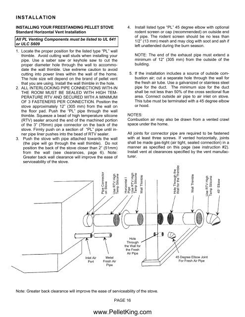
<strong>INSTALLATION</strong><br />
INSTALLING YOUR FREEST<strong>AND</strong>ING PELLET STOVE<br />
Standard Horizontal Vent Installation<br />
All PL Venting Components must be listed to UL 641<br />
or ULC S609<br />
1. Locate the proper position for the listed type “PL” wall<br />
thimble. Avoid cutting wall studs when installing your<br />
pipe. Use a saber saw or keyhole saw to cut the<br />
proper diameter hole through the wall to accommodate<br />
the wall thimble. Use extreme caution to avoid<br />
cutting into power lines within the wall of the home.<br />
The hole size will depend on the brand of pellet vent<br />
that you are using. Install the wall thimble in the hole.<br />
2. ALL INTERLOCKING PIPE CONNECTIONS WITH-IN<br />
THE ROOM MUST BE SEALED WITH HIGH TEM-<br />
PERATURE RTV <strong>AND</strong> SECURED WITH A MINIMUM<br />
OF 3 FASTENERS PER CONNECTION. Position the<br />
stove approximately 12” (305 mm) from the wall on<br />
the floor pad. Push the “PL” pipe through the wall<br />
thimble. Squeeze a bead of high temperature silicone<br />
(RTV) sealer around the end of the machined portion<br />
of the 3” (76mm) pipe connector on the back of the<br />
stove. Firmly push on a section of “PL” pipe until inner<br />
pipe liner pushes into the bead of RTV sealer.<br />
3. Push the stove with pipe attached towards the wall<br />
(the pipe will go through the wall thimble). Do not<br />
position the back of the stove closer than 2” (51mm)<br />
from the wall (see clearances, page 6). Note:<br />
Greater back wall clearance will improve the ease of<br />
serviceability of the stove.<br />
Inlet Air<br />
Port<br />
Note: Greater back clearance will improve the ease of serviceability of the stove.<br />
Pipe Connector<br />
on Stove<br />
Use RTV High<br />
Temp Silicone<br />
Metal<br />
Fresh Air<br />
Pipe<br />
PAGE 16<br />
4. Install listed type “PL” 45 degree elbow with optional<br />
rodent screen or cap (recommended) on outside end<br />
of pipe. The rodent screen should be no less than<br />
1/2” (13 mm) mesh and may clog with soot and ash if<br />
left unattended during the burn season.<br />
NOTE: The end of the exhaust pipe must extend a<br />
minimum of 12” (305 mm) from the outside of the<br />
building.<br />
5. If the installation includes a source of outside combustion<br />
air; cut a separate hole through the wall for<br />
the fresh air tube. Use a galvanized or stainless steel<br />
pipe for the duct. The minimum size for the duct<br />
shall be not less than 50% of the cross sectional flue<br />
area. Connect outside air pipe to air inlet on stove.<br />
This tube must be terminated with a 45 degree elbow<br />
or hood.<br />
NOTES:<br />
Combustion air may also be drawn from a vented crawl<br />
space under the home.<br />
All joints for connector pipe are required to be fastened<br />
with at least three screws. If vented horizontally, joints<br />
shall be made gas-tight (air tight, sealed connection) in a<br />
manner as specified on this page (see instruction #2).<br />
Install vent at clearances specified by the vent manufacturer.<br />
Horizontal l<br />
Pipe<br />
Use RTV High<br />
Temp Silicone<br />
Wall Thimble<br />
Hole<br />
Through<br />
the Wall for<br />
the Fresh<br />
Air Pipe<br />
www.<strong>Pellet</strong>King.com<br />
Hole Through the<br />
Wall for the Thimble<br />
Wall Thimble<br />
45 Degree Elbow Joint<br />
For Fresh Air Pipe<br />
Use RTV High<br />
Temp Silicone<br />
45° Elbow