Dual Amplifier Custom PCB
Dual Amplifier Custom PCB
Dual Amplifier Custom PCB

Create successful ePaper yourself
Turn your PDF publications into a flip-book with our unique Google optimized e-Paper software.
Ham Radio 101 March 2009<br />
<strong>Dual</strong> <strong>Amplifier</strong> <strong>Custom</strong> <strong>PCB</strong><br />
By Hal Silverman, WB6WXO<br />
SOARA Education Director<br />
Thanks to Brian Roode, NJ6N, for writing this report of a SOARA repeater<br />
project using an inexpensive Printed Circuit Board service.<br />
We recently suffered a failure of the radio transceiver that provided the RF link<br />
from the Temple Hill 147.645 to the Santiago 447.180 and 224.640 repeaters.<br />
A temporary mobile transceiver was put into place at the Temple Hill site. Unfortunately,<br />
after this change the audio quality through the link turned out to<br />
be poor due to the incorrect number of pre- emphasis and de-emphasis stages.<br />
A Motorola Maxtrac transceiver was procured by Tom, AE6SH. Because the<br />
pre-emphasis and de-emphasis stages on this radio are configurable, to be in<br />
circuit, or out of circuit, we thought this would make a good link radio. The<br />
only problem was matching its audio levels with the audio levels of our repeater<br />
controller.<br />
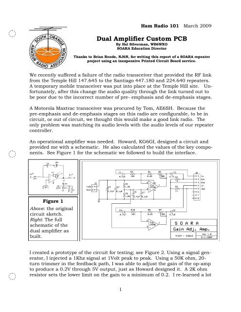
An operational amplifier was needed. Howard, KG6GI, designed a circuit and<br />
provided me with a schematic. He also calculated the values of the key components.<br />
See Figure 1 for the schematic we followed to build the interface.<br />
Figure 1<br />
Above: the original<br />
circuit sketch.<br />
Right: The full<br />
schematic of the<br />
dual amplifier as<br />
built.<br />
I created a prototype of the circuit for testing; see Figure 2. Using a signal generator,<br />
I injected a 1Khz signal at 1Volt peak to peak. Using a 50K ohm, 20-<br />
turn trimmer in the feedback path, I was able to adjust the gain of the op-amp<br />
to produce a 0.2V through 5V output, just as Howard designed it. A 2K ohm<br />
resistor sets the lower limit on the gain to a minimum of 0.2. I re-learned a lot<br />
1
about operation amplifiers through this process. If<br />
you haven't built something with an op-amp recently,<br />
you're really missing out!<br />
At some point I mentioned to Dale, W8RRV, that I<br />
needed to construct this interface circuit. He told me<br />
about a really great printed circuit board manufacturing<br />
company, www.expresspcb.com, that has a<br />
low-cost <strong>PCB</strong> manufacturing service.<br />
Figure 2<br />
I downloaded their free schematic and <strong>PCB</strong> layout<br />
Solderless Breadboard<br />
software and was able to design a circuit board in<br />
prototype of the circuit.<br />
about an hour and a half. See Figure 3 for the layout<br />
of my first <strong>PCB</strong>. I refined this one a bit before I submitted it for manufacturing.<br />
Figure 3<br />
Artwork for the <strong>PCB</strong>.<br />
The top metal layer is<br />
shown in red, and the<br />
back side layer in green.<br />
The “silkscreen” layer is<br />
shown in yellow. The<br />
finished boards do not<br />
get silkscreened Note<br />
the row of throughholes<br />
which we used to<br />
divide the board and<br />
make it easy to cut into<br />
two individual boards.<br />
Designing a circuit board using software is much faster than using etch resist<br />
"press-ons" and there is no x-acto knife or Sharpie required. Better still,<br />
there's no messing with ferric chloride etchant, and you don't have to drill all of<br />
the tiny holes yourself. You can specify what type of component is being<br />
placed using their built-in library of components or specify custom components<br />
so that the spacing, size, and number of holes required is set accordingly. The<br />
size of the circuit board traces is also configurable on a per-trace basis.<br />
The PC boards are double-sided, high quality and feature plated through "vias".<br />
The design software supports creating a ground-plane that automatically<br />
spaces your new and existing traces away from the ground plane and "thermal<br />
pads" which make it easier to solder components to the ground plane without<br />
dissipating the heat from your soldering iron.<br />
2
When you're ready to order the circuit boards you've designed, the Express<strong>PCB</strong><br />
program does some "sanity checks" and calculates the total cost.<br />
Express<strong>PCB</strong> has a "MiniBoard" service that provides three 2.5" x 3.8" boards<br />
for $51 plus 7.75% tax and $9.85 shipping. Boards are shipped the next<br />
business day by 2nd day air after your order is placed via the internet. The<br />
total cost comes out to about 65 dollars..<br />
The neat thing is that you can<br />
create as many circuits as will fit on<br />
their MiniBoard for the same price, as<br />
long as you don't go over the total number<br />
of holes. For my first board, I divided<br />
the board in half and made two<br />
identical circuits on each side. If I had<br />
spent more time, I could probably have<br />
fit four of them on one board.<br />
The finished product can be seen in Figure<br />
4. I enclosed the circuit board in a<br />
die-cast aluminum enclosure and installed<br />
it between the Maxtrac radio and<br />
our repeater controller and fine-tuned<br />
the amplifier gain adjustments. You<br />
can hear the results during the next<br />
Tuesday night SOARA net on the<br />
147.645, 224.640, and 447.180 repeaters.<br />
73, NJ6N<br />
Figure 4<br />
Top view of the completed dual<br />
amplifier circuit. The 8-pin dual op<br />
amp (LM358) can be seen in the<br />
socket at the upper right. Input and<br />
output leads are connected at the<br />
vertical row of through holes at the<br />
left. Note the labeling made in the top<br />
metal layer.<br />
3