9.0 MHz Crystal Oscillator
9.0 MHz Crystal Oscillator
9.0 MHz Crystal Oscillator

You also want an ePaper? Increase the reach of your titles
YUMPU automatically turns print PDFs into web optimized ePapers that Google loves.
Ham Radio 101 February 2011<br />
SOARA Workshop<br />
<strong>9.0</strong> <strong>MHz</strong> <strong>Crystal</strong> <strong>Oscillator</strong><br />
By Hal Silverman WB6WXO<br />
SOARA Education Director<br />
In the last article, I presented the final version of the 5.0 to 5.5 <strong>MHz</strong> VFO. In this article I describe<br />
the design and construction of a <strong>9.0</strong><strong>MHz</strong> crystal oscillator. The circuits in these articles<br />
are not new and innovative circuits. They represent the fundamental circuits that are used and<br />
were used to develop ham radio transmitters, receivers and transceivers.<br />
A classic design is to take the VFO described in the last article and a <strong>9.0</strong><strong>MHz</strong> crystal oscillator<br />
and mix them to get the difference frequency of 3.5<strong>MHz</strong> to 4.0<strong>MHz</strong> (80m and 75m) or the sum<br />
frequency of 14.0<strong>MHz</strong> to 14.5Mhz (20M).<br />
If the designer is looking for just a CW transmitter then the 3.5<strong>MHz</strong> can be fed to a frequency<br />
doubler and yield 7.0<strong>MHz</strong> to 7.5<strong>MHz</strong> (40M). In a similar manner, the 14.0MHZ can be doubled<br />
into a 28.0<strong>MHz</strong> to 28.5<strong>MHz</strong> (10M) frequency.<br />
The circuits come from a variety of ARRL handbooks. I also use an older QRP handbook from<br />
1990. In most cases, the tubes outlined in the early handbooks can use a MOSFET as a substitute.<br />
Dual gate MOSFETs can be used as mixer devices.<br />
OK, now let us look at the<br />
oscillator. There are two<br />
popular designs for RF oscillators.<br />
The Hartley oscillator<br />
uses a transformer for<br />
positive feedback. The Colpitts<br />
design uses capacitive<br />
feedback to achieve an oscillation.<br />
I prefer to use the<br />
Colpitts design.<br />
<strong>9.0</strong>0Mhz<br />
100K<br />
2N5484<br />
100pf<br />
27pf<br />
13.8V 13.8V<br />
2.2uhy<br />
.1ufd<br />
.1ufd<br />
.1ufd<br />
5~65pf<br />
100K 2N5484<br />
RFC<br />
100K<br />
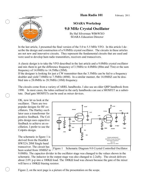
The schematic in figure 1 is<br />
derived from the Heathkit<br />
HW32A 20M Single band<br />
transceiver. The circuit has<br />
been scaled from 18MHZ to<br />
Figure 1<br />
<strong>9.0</strong><strong>MHz</strong>. The capacitor divider in the oscillator stage was changed to the values shown in the<br />
schematic. The inductor in the output stage was also changed to 2.2uHy. The circuit delivers<br />
about 2.0V p-p into a 100KΩ load. The 100KΩ load was chosen because the gate of the mixer<br />
will have a 100KΩ biasing resistor.<br />
Figure 2, on the next page is a picture of the presentation on the scope.<br />
560<br />
SOARA WORKSHOP<br />
<strong>9.0</strong>0 Mhz <strong>Crystal</strong> <strong>Oscillator</strong><br />
Hetrodyne Oacillator<br />
Rev n/c<br />
December 22, 2010<br />
Schematic Diagram <strong>9.0</strong> <strong>Crystal</strong> Controlled <strong>Oscillator</strong>
Figure 2<br />
Waveform of the <strong>9.0</strong><strong>MHz</strong> oscillator<br />
From figure 2, the designer can see the waveform. This waveform is acceptable as a decent<br />
sine wave. There is enough output voltage to drive a dual gate MOSFET mixer.<br />
I also wanted to get an idea of<br />
how stable the output was. I<br />
used counter and made periodic<br />
observations. The output voltage<br />
stayed rock-solid over a several<br />
day period. This is a vast<br />
improvement over a tube type<br />
design as it takes time for the<br />
transmitter/receiver/transceiver<br />
to warm and the components to<br />
stabilize.<br />
Figure 3<br />
Counter used to check stability<br />
Figures 4 and 5 are the layouts I used. I prefer to use a solderless breadboard and then a solderable<br />
board. The final design should have a PCB layout.<br />
February 2011 Page 2
At these frequencies, lead<br />
length is not as important as<br />
it is at 5O<strong>MHz</strong> and above.<br />
As the frequency goes up,<br />
leads become small inductors<br />
and can affect performance.<br />
As you can see, with some<br />
judicious planning, the<br />
mixer circuit can be assembled<br />
on this breadboard.<br />
Both the solderless bread<br />
board and the soldered<br />
breadboard had approximately<br />
the same output.<br />
The cost to assemble this<br />
circuit is about $20.00. The<br />
main expense is the crystal.<br />
I found a web site and ordered<br />
two. They were $12<br />
each plus $5 shipping.<br />
The web site is http://<br />
AF4K.com/crystals.htm<br />
His name is Brian Carling<br />
AF4K. He can be reached at<br />
321-262-5471. His E Mail<br />
address is af4k@af4k.com<br />
Figure 4<br />
Solderless Breadboard Layout.<br />
If anyone wants to do this<br />
project, let me know and I<br />
Figure 5<br />
Breadboard Layout<br />
will provide a parts list and a schematic.<br />
My next project is to develop a mixer that is compatible with the VFO and the crystal oscillator.<br />
My plan is to report on that in the next Ham Radio 101<br />
If there are any other questions or comments, drop me a note at WB6WXO@SOARA.com<br />
February 2011 Page 3