MP50 Compressor/Controller - QED Environmental Systems
MP50 Compressor/Controller - QED Environmental Systems
MP50 Compressor/Controller - QED Environmental Systems

You also want an ePaper? Increase the reach of your titles
YUMPU automatically turns print PDFs into web optimized ePapers that Google loves.
U<br />
O<br />
asics<br />
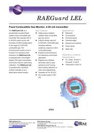
<strong>MP50</strong><br />
MODEL<br />
CONTROLLER/COMPRESSOR<br />
PATENT PENDING<br />
Instruction<br />
Manual<br />
Part No. 95258 2-15-10<br />
P.O. Box 3726 Ann Arbor, MI 48106-3726 USA<br />
1-800-624-2026 Fax (734) 995-1170<br />
info@qedenv.com www.qedenv.com
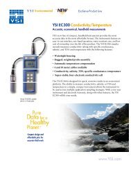
<strong>MP50</strong> Basic Setup<br />
Pump Air Supply<br />
Pump Discharge<br />
Well<br />
Cap<br />
<strong>MP50</strong><br />
<strong>Controller</strong><br />
Optional<br />
MP30 Drawdown<br />
Meter<br />
Tubing<br />
Well Wizard<br />
Bladder<br />
Pump<br />
R
Contents<br />
Topic<br />
Safety Warnings<br />
Page<br />
1<br />
Conventions and Diagrams<br />
1<br />
Introduction / Quick-Start<br />
4<br />
Bladder Pump Operation in Low-Submergence Applications<br />
6<br />
Turning the <strong>MP50</strong> On<br />
7<br />
Opening Display<br />
7<br />
MicroPurge Mode<br />
8<br />
Using CPM<br />
8<br />
Sampling<br />
10<br />
Use with the MP30 Level Sensing Water Level Meter<br />
11<br />
ID Mode<br />
14<br />
User Time Set (MN) Mode<br />
15<br />
<strong>MP50</strong> Battery<br />
16<br />
Troubleshooting<br />
17<br />
<strong>MP50</strong> Specifications<br />
18<br />
<strong>QED</strong> Service Contacts<br />
19<br />
<strong>QED</strong> Warranty<br />
20<br />
Appendix 1 ID Data Table<br />
21
Safety Warnings<br />
Safety warnings<br />
Compressed air - Use caution when working with compressed air or gas. Compressed gas<br />
cylinders are under extreme pressure and can cause unrestrained hoses to whip about dangerously.<br />
Do not over pressurize your controller. Failure to operate the controller within the pressure<br />
limits could result in failure. Read all operating instructions before operating the <strong>MP50</strong><br />
controller.<br />
Warning - Do not disassemble the pneumatic pump while it is connected to a compressed gas<br />
source. Dangerous pressures could cause injury.<br />
Diagrams and Conventions used in the Text<br />
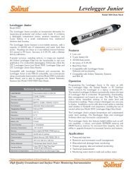
<strong>MP50</strong> Panel Layout:<br />
Battery<br />
Cover<br />
Connector for optional<br />
MP30 Drawdown Control<br />
Battery<br />
Connectors<br />
Compressed<br />
Gas Source<br />
Connection<br />
<strong>Controller</strong><br />
To Pump<br />
Connection<br />
<strong>Compressor</strong><br />
Fan<br />
<strong>MP50</strong> Control<br />
Keypad and<br />
display<br />
Pressure<br />
Gauge<br />
Discharge<br />
cycle<br />
indicator<br />
Flow<br />
Throttle<br />
1
Diagrams / Conventions<br />
Diagrams And Conventions Used In The Text (Cont.)<br />
<strong>MP50</strong> Control Keys:<br />
In MP Mode<br />
In Other Modes<br />
MicroPurge Basics <strong>Controller</strong><br />
MP Micro Purge<br />
ID ID Time Set<br />
Mode<br />
CPM<br />
Time<br />
MN Manual Time Set<br />
LVL LevelShutoff<br />
ID<br />
Refill<br />
00.1 103 10.0<br />
MP CPM4 >05.0<br />
Discharge<br />
Cycle Per Minute<br />
key - Changes<br />
cycle per minute<br />
Faster key -<br />
Speeds up flow<br />
Slower key -<br />
Slows down<br />
flow<br />
Scrolls cursor<br />
Changes a value<br />
at the cursor<br />
location<br />
Changes a value<br />
at the cursor<br />
location<br />
CPM/Value Flow/Value Flow/Value<br />
CYCLE<br />
Start/Stop<br />
MODE<br />
ID/MN/MP/<br />
Battery<br />
I I<br />
Hold/Sample<br />
/Cycle<br />
ED<br />
Pause key -<br />
Pauses flow for<br />
sampling<br />
Mode key -Selects<br />
the operation<br />
mode. Also battery<br />
check<br />
Cycle key -Selects<br />
Start and Stop of<br />
pump cycling<br />
CPM Button (also scroll for<br />
item selects)<br />
CYCLE<br />
CYCLE Button<br />
UP Button, faster pumping<br />
(also increase item)<br />
DOWN Button, slower<br />
pumping (also decrease<br />
item)<br />
MODE<br />
I I<br />
MODE Button (also battery<br />
check)<br />
PAUSE Button (also<br />
manual sample)<br />
2
Diagrams / Conventions<br />
Diagrams And Conventions Used In The Text (Cont.)<br />
<strong>MP50</strong> Display:<br />
Time<br />
remaining<br />
in the cycle<br />
ID for time<br />
settings<br />
Refill time<br />
setting in<br />
seconds<br />
00.1 103 10.0<br />
Discharge time<br />
setting in<br />
MP CPM4 >05.0<br />
seconds<br />
The mode the<br />
controller is in<br />
Cycles per<br />
minute setting<br />
Indicates if<br />
pump is<br />
Refilling or<br />
Discharging<br />
Abbreviations:<br />
CPM<br />
MP<br />
ID<br />
HELD<br />
MN<br />
BAT<br />
LVL<br />
><br />
Cycles Per Minute<br />
MicroPurge Mode<br />
ID Time Set Mode<br />
Held In A Cycle<br />
Manual Time Set Mode<br />
Battery<br />
Level Pause<br />
Indicates Refill Or Discharge Cycle<br />
3
Introduction / Quick Start<br />
Introduction / Quick Start<br />
Introduction: The <strong>MP50</strong> Micro Purge Basics <strong>Controller</strong>/<strong>Compressor</strong> is used to operate <strong>QED</strong><br />
Well Wizard bladder sampling pumps to purge and sample ground water. The <strong>MP50</strong> has<br />
specific design features to make MicroPurge sampling easier. These features include:<br />
MicroPurge Mode Operation Simple Increase / Decrease keys allow you to easily set<br />
the flow rate you need for each well.<br />
ID Time Set Mode Operation Quickly recalls pre-determined settings for each well by<br />
specifying a 3-digit ID.<br />
Level Delay Interface The controller plugs into the optional MP30 MicroPurge Drawdown<br />
/ Water Level Meter to provide direct feedback of well drawdown and to pause<br />
pump operation until the level recovers.<br />
The optional MP30 MicroPurge Drawdown / Water Level Meter plugs into the <strong>MP50</strong> to provide<br />
water level feedback. The MP30 uses a standard conductivity probe to detect the<br />
ground water surface and a marked tape allowing the user to measure the depth. When the<br />
meter is set in MicroPurge mode, the probe is lowered a specific distance below the static<br />
water level and fixed in this position. During well sampling if the water level drops below<br />
the user-set probe position, the <strong>MP50</strong> is paused which prevents further drawdown by the<br />
pump. Once the level recovers the <strong>MP50</strong> begins pump operation again, starting in the pump<br />
refill cycle. Use of the <strong>MP50</strong> with the MP30 is detailed later in this manual.<br />
Insert Batteries: Remove the battery cover on the top of the <strong>MP50</strong>. Insert 3, AA alkaline batteries<br />
into the battery holder and carefully replace the holder in the carrier. Replace the<br />
battery cover and tighten the 4 screws. Batteries should last for about 6-8 weeks of typical<br />
full-time field use. If the <strong>MP50</strong> will be stored longer than about 3 months, the alkaline batteries<br />
should be removed to prevent leakage.<br />
4
Introduction / Quick Start<br />
Quick Start: Attach Red Positive (+) cable clamp to the Positive (+)<br />
terminal of battery. Attach Black Negative (-) cable clamp to the<br />
Negative (-) terminal of battery. Connect the light blue coiled pump hose<br />
to the fitting labeled “AIR OUT” on the <strong>MP50</strong>. Turn the controller throttle<br />
until the gauge reads the approximate depth of the sample pump (See<br />
Page 6) Follow instructions on the battery panel:<br />
Opening the <strong>MP50</strong> case turns power ON.<br />
Note: It may take up to 20 seconds for the unit to power up.<br />
Select desired Cycles Per Minute (CPM) with (default value is 4<br />
CPM, lower CPM for deeper wells, higher CPM possible with shallow<br />
wells- See Page 6) .<br />
Turn throttle to set depth on gauge to 10-20 feet deeper than the pump<br />
location in the well.<br />
Press<br />
Cycle<br />
to START pumping.<br />
When water discharge begins, adjust throttle until a slow, steady flowstream<br />
is achieved.<br />
Press<br />
keys to set the desired purge flow rate.<br />
To collect samples, continue purge flow, or use<br />
control sample flow and pause.<br />
Note: An option to use an external air source is built into the <strong>MP50</strong>. To<br />
use external air source (rather than the built-in air compressor) simply<br />
connect the air source to the “Air In” port.<br />
I I<br />
key to directly<br />
Note: A moisture vent is provided and located on the side of the <strong>MP50</strong><br />
case. Excessive accumulation of moisture can impede proper operation<br />
of the <strong>MP50</strong>. During cold and/or damp weather conditions, it is<br />
recommended that the moisture vent be pushed at frequent intervals<br />
during operation of the <strong>MP50</strong>.<br />
5
Bladder Pump Operation In Low-Submergence<br />
Bladder Pump Operation In Low-Submergence Applications<br />
Pump submergence is defined as the height of the static water column above the top of the<br />
pump. In wells in which this water column height is 5 feet or less, the pump is considered to be<br />
in a low-submergence application.<br />
<strong>QED</strong> sampling bladder pumps fill by hydrostatic pressure. As the inside of the pump's bladder<br />
fills with water, the bladder expands. This filling and expanding of the bladder is referred to as<br />
the "refill" half of the pump cycle. When air pressure is applied to the outside of the bladder, the<br />
bladder is squeezed, forcing the water up the discharge tubing. This is referred to as the<br />
"discharge" half of the pump cycle. In low-submergence applications, there is less water pressure<br />
available to expand the bladder during the refill.<br />
This can result in a smaller volume of water being pumped with each pump cycle because the<br />
bladder may not fully expand.<br />
As a result of the lower volume per cycle, more time will be required to bring the water to the<br />
surface. An easy way to verify that the pump is working, prior to the water reaching the surface,<br />
is to submerge the pump's discharge tubing in a beaker of water. Each time the pump goes into<br />
discharge, air in the discharge tubing, which is displaced as the water level in the tubing rises,<br />
can be seen as air bubbles coming from the end of the tubing. To optimize the pumping rate,<br />
the refill time should be set long enough to achieve the maximum volume of air bubbles on<br />
each pump cycle, and the discharge time should be set long enough to ensure that the air has<br />
stopped bubbling out of the tube before the pump controller switches back into refill.<br />
In low submergence wells, it is critical that the air pressure driving the pump not be more<br />
than 10-15psi higher than the minimum requirement of 0.42psi per foot of pump depth.<br />
Higher pressures than this can cause the bladder to be squeezed too tightly during discharge,<br />
a condition which can prevent the bladder from expanding during refill. To avoid this condition<br />
in deeper wells, it is suggested that the air pressure applied to the pump be gradually increased<br />
as the water level in the pump's discharge tubing rises. It is recommended that the air pressure<br />
be set at 15 psi initially, and slowly increased in increments of 10 psi as needed until the water<br />
reaches the surface. Submerging the end of the discharge tubing under water as described<br />
above will verify whether the air pressure is set high enough. .<br />
6
Operation<br />
Operation<br />
Turning the <strong>MP50</strong> Display On - The <strong>MP50</strong> is powered on automatically by opening the lid.<br />
The <strong>MP50</strong> displays an opening screen for 5 seconds, after which it displays the default Micro-<br />
Purge screen. At this point the <strong>MP50</strong> is in MicroPurge mode (MP) but not cycling the pump.<br />
This initial state allows the user to adjust time and throttle settings before the pump starts to<br />
operate. Pressing the Cycle key begins pump cycling. Times and modes may be adjusted<br />
while the pump is cycling or before. Pressing the Cycle key a second time will stop pump<br />
cycling.<br />
Note: all user-entered time settings are lost when the <strong>MP50</strong> is turned off. Also, the <strong>MP50</strong><br />
automatically powers down when the lid is closed, so make sure the <strong>MP50</strong> is stored with its<br />
lid closed.<br />
Opening Display - The opening display is shown for 5 seconds and displays the controller<br />
name, the version number and the battery voltage, as shown in Figure 1. Figure 1 shows that<br />
the battery is GOOD, that the battery voltage is 4.20 volts and that the software version in the<br />
cont-roller is 1.0. Battery voltage must be greater than 3.6 volts for the unit to operate. If the<br />
unit fails to cycle replace the 3-AA batteries with fresh cells. The opening screen is displayed<br />
for 5 seconds, if you wish to by pass the opening screen, hitting any key, such as the CPM key<br />
will bring you to the default MP display.<br />
Figure 1 Opening Screen<br />
MicroPurge Basics <strong>Controller</strong><br />
MP Micro Purge<br />
ID ID Time Set<br />
MN Manual Time Set<br />
LVL LevelShutoff<br />
Time<br />
Mode<br />
CPM<br />
Discharge<br />
ID<br />
Refill<br />
<strong>QED</strong> MP10 V1.0<br />
BAT GOOD 4.20<br />
CPM/Value Flow/Value Flow/Value<br />
CYCLE<br />
MODE<br />
I I<br />
Start/Stop<br />
ID/MN/MP/<br />
Battery<br />
Hold/Sample<br />
/Cycle<br />
ED<br />
7
Operation<br />
MicroPurge Mode Most <strong>MP50</strong> users will leave the controller in the default MicroPurge (MP)<br />
mode. See Figure 2 for an example of the <strong>MP50</strong> in MP mode. MP mode lets you to use the<br />
UP and DOWN keys to directly increase and decrease pump flow rates. The <strong>MP50</strong> has a<br />
broad range of other CPM settings to ensure the availability of a time setting that will match<br />
your specific conditions. MP mode also displays an ID, with a value of 1 to 165 that matches<br />
the flow settings (CPM and refill and discharge times you have set). This ID should be noted<br />
alongside the well identification (<strong>QED</strong> provides custom weatherproof ID badges for purchasers<br />
of our MP series of well caps) for quick setting of the optimal controller settings on the next<br />
visit by using the <strong>MP50</strong> in ID mode.<br />
Figure 2 <strong>MP50</strong> MicroPurge Mode<br />
MicroPurge Basics <strong>Controller</strong><br />
MP Micro Purge<br />
ID ID Time Set<br />
MN Manual Time Set<br />
LVL LevelShutoff<br />
Time<br />
Mode CPM<br />
Discharge<br />
ID<br />
Refill<br />
00.1 103 10.0<br />
MP CPM4 >05.0<br />
CPM/Value Flow/Value Flow/Value<br />
CYCLE<br />
MODE<br />
I I<br />
Start/Stop<br />
ID/MN/MP/<br />
Battery<br />
Hold/Sample<br />
/Cycle<br />
ED<br />
Using CPM The <strong>MP50</strong> introduces a revolutionary, simpler way to control bladder pump flow<br />
rate and achieve the low-flow method used by experts. Up/down arrow keys are used to adjust<br />
pump flow even at very low rates, with excellent control and repeatability.<br />
With previous bladder pump controllers, a leading low-flow technique called for selecting the<br />
number of pump cycles per minute, then adjusting the bladder pump discharge and refill times<br />
to achieve the desired volume per cycle. These adjustments were interrelated, complex, and<br />
varied by operator. The new MicroPurge Mode (MP) of the <strong>MP50</strong> builds in a "cycles per<br />
minute", or CPM, method of flow control.<br />
8
Operation<br />
With this method, the number of complete pump cycles per minute is fixed, within a range of 1<br />
to 6; 4 CPM is the default value which appears at startup. Each time the up/down arrow keys<br />
are pressed, the pump refill and discharge times are both automatically adjusted to maintain<br />
the selected CPM value. Each adjustment increases or decreases the volume pumped per<br />
cycle, and the per-minute flow rate is the volume per cycle X the CPM value.<br />
For example, with a 4 CPM setting, 60 ml volume per cycle equates to 4 X 60 = 240 ml/min<br />
flow rate. A single press of the Flow up arrow key could change the volume per cycle to 80 ml,<br />
for example, resulting in a new, increased flow rate of 4 X 80 = 320 ml/min. And the MP10<br />
assigns a unique identification value to each setting, the ID value, which can be directly set<br />
during later sampling events.<br />
"MP" displayed in the lower left corner of the display indicates MicroPurge mode. The default<br />
CPM setting of 4 cycles per minute is a good starting point for wells with depths from 25-100 ft.<br />
MicroPurge mode starts at a time setting of 10 seconds refill and 5 seconds discharge, close to<br />
optimal for many wells. This startup settings corresponds to a 4 cycles per minute setting<br />
(CPM4) and an ID setting of 103.<br />
Using the CPM key will change the CPM setting on the controller. The range of CPM settings<br />
is CPM1 through CPM6. CPM changes like this each time you hit the CPM key: 4 5 6 1 2 3<br />
4 5, etc. The UP and DOWN keys change the flow rate directly, by altering the refill and discharge<br />
times within a CPM setting.<br />
Note: changes in settings that are entered while the controller is cycling are reflected on the<br />
next cycle change (so a long refill time of 15 seconds will time out before a new refill time becomes<br />
valid).<br />
Here is an example of the use of the UP (faster) key:<br />
Key Press<br />
Refill Discharge ID<br />
(sec) (sec)<br />
---<br />
1<br />
2<br />
3<br />
10.0<br />
9.5<br />
9.0<br />
8.5<br />
5.0<br />
5.5<br />
6.0<br />
6.5<br />
103<br />
104<br />
105<br />
106<br />
9
Operation<br />
Each of the 165 possible ID settings corresponds to a unique ID that is associated with CPM, refill<br />
and discharge time values. For typical usage, only the UP/DOWN arrow keys are required to set<br />
flow, and the ID number is provided for easy, direct return to past settings. Appendix 1 lists all possible<br />
ID settings and the default refill and discharge time settings for each CPM. Appendix 1 also<br />
shows how the refill and dis-charge time will change within a CPM setting as you press the UP or<br />
DOWN keys.<br />
Sample Collection The PAUSE key ( I I ) is used to freeze the controller action to allow the<br />
user time to collect a sample or carry out other steps that might be difficult if the controller continued<br />
to automatically cycle and cause the pump to produce water. While the controller is cycling,<br />
pressing the PAUSE key causes the controller to immediately enter the Hold state. Drive air is<br />
vented from the pump (this is the pump refill cycle) and the pump fills and waits. Pressing the<br />
PAUSE key a second time causes the controller to immediately enter the Sample state. Drive air<br />
is directed to the pump causing the pump to discharge its volume of liquid. Bladder pumps typically<br />
hold 400-500 ml of liquid, so use of the Hold and Sample states allow the full volume of the<br />
pump to be discharged into a sample container. Pressing PAUSE once again returns the <strong>MP50</strong> to<br />
its normal Automatic Cycling state. During Hold and Sample a HELD is displayed to remind you<br />
that the controller is in a paused state. Figure 3 shows an example of the <strong>MP50</strong> in MP mode, but<br />
HELD in the Sample state.<br />
Note: Pressing the Cycle key also freezes controller cycling. However, using the Cycle key rather<br />
than the Pause key causes the startup screen to be displayed upon restart. Use of the Pause key<br />
is recommended for typical operation.<br />
Figure 3 <strong>MP50</strong> Held State (MP mode)<br />
MicroPurge Basics <strong>Controller</strong><br />
MP Micro Purge<br />
ID ID Time Set<br />
MN Manual Time Set<br />
LVL LevelShutoff<br />
Time<br />
Mode CPM<br />
Discharge<br />
ID<br />
Refill<br />
HELD 103 10.0<br />
MP CPM4 >05.0<br />
CPM/Value Flow/Value Flow/Value<br />
CYCLE<br />
MODE<br />
I I<br />
Start/Stop<br />
ID/MN/MP/<br />
Battery<br />
Hold/Sample<br />
/Cycle<br />
ED<br />
10
Operation<br />
Warning: in the HELD SAMPLE state the pump, tubing and hoses are all under pressure.<br />
DO NOT attempt to disconnect or disassemble any part of the system when it is under pressure.<br />
The system is under pressure if the pressure gauge shows a value greater than 0 and<br />
the RED Discharge Cycle Indicator is showing.<br />
Flow Throttle Use The flow throttle is used during sampling to regulate the pressure applied<br />
to the pump. Turning the throttle clockwise increases the pressure and counterclockwise decreases<br />
the pressure. The pressure gauge shows the approximate pressure applied to the<br />
pump and reads in units of Feet - H²O. This allows easy adjustment of the throttle giving pressures<br />
that will produce gentle, non-turbulent flow (normally 10-20 Feet - H²O deeper than pump<br />
depth). For traditional, high volume purging pressure may be increased with the throttle to<br />
maximize pump flow during well purging.<br />
Use with the MP30 Automatic Drawdown Control The <strong>MP50</strong> may optionally be used with the<br />
MP30 MicroPurge Drawdown / Water Level Meter. See Figure 4 for an example of the <strong>MP50</strong> in<br />
MP mode with the controller in a level paused state enacted by an MP30 meter.<br />
Figure 4 <strong>MP50</strong> Level Paused State (MP mode)<br />
MicroPurge Basics <strong>Controller</strong><br />
MP Micro Purge<br />
ID ID Time Set<br />
MN Manual Time Set<br />
LVL LevelShutoff<br />
Time<br />
Mode CPM<br />
Discharge<br />
ID<br />
Refill<br />
LVL 10.0<br />
MP CPM4 >05.0<br />
CPM/Value Flow/Value Flow/Value<br />
CYCLE<br />
MODE<br />
I I<br />
Start/Stop<br />
ID/MN/MP/<br />
Battery<br />
Hold/Sample<br />
/Cycle<br />
ED<br />
11
Operation<br />
Figure 5 <strong>MP50</strong> MP30 Use<br />
<strong>MP50</strong> MP10<br />
MP30<br />
Normal<br />
Static<br />
Level<br />
Maximum Point<br />
of Drawdown<br />
Figure 6 <strong>MP50</strong> MP30 Use<br />
Connector for optional<br />
MP30 Drawdown Control<br />
O<br />
MODEL MP10<br />
U<br />
asics CONTROLLER<br />
ED<br />
MicroPurge Mode Mode Quick Quick Guide Guide<br />
1. Opening cover turns power ON. (Close to turn OFF.)<br />
2. Select desired Cycles Per Minute (CPM) with the key<br />
(default value is 4 CPM).<br />
3. Turn throttle to set depth on gauge to 10-20 feet<br />
deeper than the pump location in the well.<br />
4. Press CYCLE to START pumping.<br />
5. When water discharge begins, adjust throttle until<br />
a slow, steady flowstream is achieved.<br />
6. Press keys to set the desired purge flow.<br />
7. Use II key to directly control sample flow and pause.<br />
3 AA BATTERIES INSIDE<br />
MicroPurge Basics <strong>Controller</strong><br />
MP Micro Purge MN Manual Time Set<br />
ID ID Time Set LVL LevelShutoff<br />
CONTROL PORT<br />
ED<br />
1-800-624-2026<br />
micropurge.com<br />
AIR IN<br />
Compressed gas source<br />
connection<br />
<strong>Controller</strong> to pump<br />
connection<br />
Time<br />
Mode CPM<br />
Discharge<br />
ID<br />
Refill<br />
00.1 103 10.0<br />
MP CPM4 >05.0<br />
AIR OUT<br />
DISCHARGE CYCLE<br />
Discharge cycle<br />
indicator<br />
CPM/Value Flow/Value Flow/Value<br />
CYCLE MODE I I<br />
Flow throttle<br />
Start/Stop<br />
ID/MN/MP/<br />
Battery<br />
Hold/Sample<br />
/Cycle<br />
ED<br />
0<br />
psi<br />
THROTTLE<br />
12
Operation<br />
The <strong>MP50</strong> and MP30 are connected with a cable (see Figures 5 and 6). The MP30 is switched<br />
into mode and the water level probe is lowered to the desired maximum drawdown level.<br />
Limiting the maximum drawdown depth limits the differential head driving flow into the well and<br />
the velocity of the water flowing into the well from the surrounding formation important in Micro-<br />
Purge sampling. The <strong>MP50</strong> and MP30 work together to automatically adjust the pump operation<br />
so as to maintain drawdown at the set level. When the water level drops below the probe,<br />
the MP30 sends a signal to the <strong>MP50</strong> to pause pumping. Both the <strong>MP50</strong> and the MP30 give<br />
visual signals (and the MP30 emits an audio signal) that pump operation has stopped because<br />
of too much drawdown. Once the level recovers, the MP30 signals the <strong>MP50</strong> to resume pump<br />
operation. The <strong>MP50</strong> resumes by starting in the refill leg of the pump cycle. "DRAWDOWN<br />
CONTROL"<br />
The normal operating mode for using the MP30 with the <strong>MP50</strong> is:<br />
1. Use the MP30 in standard WLM mode to determine the static water level in the well<br />
2. Decide what the maximum drawdown for that well is during sampling<br />
3. Lower the probe to the maximum drawdown level<br />
4. Switch the MP30 into Drawdown Control mode<br />
5. Begin pumping with the <strong>MP50</strong><br />
6. Observe the interactions between the two devices, if the MP30 is frequently pausing the<br />
<strong>MP50</strong>, it may be appropriate to slow the flow down (using the DOWN key in MP mode) to<br />
better match pump flow to well recharge.<br />
When switched into mode, the MP30 has a flashing red light and an optional (can be switched<br />
off by the user) audio alarm to indicate when the probe is in the dry state. A submerged probe<br />
in all modes is indicated by a solid green light. When the <strong>MP50</strong> is paused by the MP30 the MP<br />
50 display indicates this as shown in Figure 4 "DRAWDOWN CONTROL"<br />
13
Operation<br />
If the MP30 is signaling the <strong>MP50</strong> too frequently, the operator can slow down the pump flow<br />
rate by using the DOWN key (effectively increasing the pump refill time period). MP30 probe<br />
position may also be varied to provide a buffer zone for your drawdown limit and gauge rate of<br />
pumping effect on water level in the well.<br />
If the selected maximum drawdown level is being reached even with the lowest desirable pump<br />
flow rate more drawdown may be required to attain equilibration, or a passive sampling approach<br />
may be required. In passive sampling, used where well recovery is extremely slow, samples<br />
are taken after just a few pump strokes sufficient to purge the pump and tubing volumes.<br />
Additional information on the MP30 is given in the MP30 O&M manual<br />
ID Mode Figure 6 shows an example of the <strong>MP50</strong> in ID time set mode. Once you've used the<br />
<strong>MP50</strong> in MP mode and found proper settings for your wells, subsequent sampling events are<br />
speeded along by using the controller in ID mode. Once the controller is turned on, a single<br />
press of the MODE key places the controller in ID time set mode (the default initial mode is MP<br />
mode). This mode allows the user to enter a 3-digit ID, which then is translated into the correct<br />
flow settings (CPM and refill / discharge time settings) for that well.<br />
Figure 7 <strong>MP50</strong> ID Set Mode<br />
MicroPurge Basics <strong>Controller</strong><br />
MP Micro Purge<br />
ID ID Time Set<br />
MN Manual Time Set<br />
LVL LevelShutoff<br />
Time<br />
Mode CPM<br />
Discharge<br />
ID<br />
Refill<br />
00.1 103 10.0<br />
MP CPM4 >05.0<br />
CPM/Value Flow/Value Flow/Value<br />
CYCLE<br />
MODE<br />
I I<br />
Start/Stop<br />
ID/MN/MP/<br />
Battery<br />
Hold/Sample<br />
/Cycle<br />
ED<br />
14
Operation<br />
In this mode the CPM and UP, DOWN keys function differently. The CPM key becomes a key<br />
used to scroll between the one's and the ten's digits of the ID. The UP and DOWN keys are<br />
used to change the ID number (the <strong>MP50</strong> has IDs that range from 1-165) up or down in value.<br />
Sampling in ID mode is the same as explained, above, for MP mode.<br />
Appendix 1 lists all possible ID settings and the default refill and discharge time settings for<br />
each CPM. Appendix 1 also shows how the refill and discharge time will change within a CPM<br />
setting as you press the UP or DOWN keys. As you change IDs you will see the CPM change<br />
and the refill and discharge time setting change.<br />
Note: changes in time settings that are entered while the controller is cycling are reflected on<br />
the next cycle change (so a long refill time of 15 seconds will time out before a new refill time<br />
becomes valid).<br />
User Set Mode A final controller mode, User Set mode (MN on the display), is useful for manually<br />
setting refill and discharge times on the controller as in traditional controllers (like previous<br />
model <strong>QED</strong> pump controllers). An example of the <strong>MP50</strong> in User Set mode is shown in Figure<br />
8. User set mode is also used when the wells being sampled are at extreme depths or there<br />
are other conditions where one of the 165 possible preset times of ID and MP modes will not<br />
match your needs. MN mode is entered when the MODE key is pressed twice from the default<br />
MP mode. As shown in Figure 8, the display indicates MN mode in the lower left corner and<br />
CPM and ID are not displayed.<br />
Figure 8 <strong>MP50</strong> User Set Mode (MN mode)<br />
MicroPurge Basics <strong>Controller</strong><br />
MP Micro Purge<br />
ID ID Time Set<br />
MN Manual Time Set<br />
LVL LevelShutoff<br />
Time<br />
Mode CPM<br />
Discharge<br />
ID<br />
Refill<br />
00.1 10.0<br />
MN >05.0<br />
CPM/Value Flow/Value Flow/Value<br />
CYCLE<br />
MODE<br />
I I<br />
Start/Stop<br />
ID/MN/MP/<br />
Battery<br />
Hold/Sample<br />
/Cycle<br />
ED<br />
15
Operation<br />
In User Set mode the CPM and UP, DOWN keys function differently than MP mode. The CPM<br />
key becomes a key used to select the digits of the refill and discharge time settings found at<br />
the rightmost positions on the display. The UP and DOWN keys are used to adjust the digit<br />
value up or down. By selecting and adjusting digits up and down a user can quickly set any<br />
time from 00.1 seconds to 99.9 seconds. Sampling in User Set mode is the same as explained,<br />
above, for MP mode.<br />
The <strong>MP50</strong> does not attempt to translate a user set time into a corresponding ID or CPM. Also,<br />
any settings you have entered in MP or ID modes are lost once you press the MODE key to<br />
enter MN mode.<br />
Note: changes in time settings that are entered while the controller is cycling are reflected on<br />
the next cycle change (so a long refill time of 15 seconds will time out before a new refill time<br />
becomes valid).<br />
<strong>MP50</strong> Battery - The <strong>MP50</strong> features sophisticated power-supply circuitry that optimizes battery<br />
life. A fresh set of AA batteries will provide more than 100 hours of controller operation at<br />
normal operating temperatures. As ambient temperatures drop below 15-20˚F (-9˚C to -6˚C),<br />
the ability of the alkaline batteries to deliver energy is affected. Continuous operation may be<br />
difficult in extremely cold conditions. Once the batteries and <strong>MP50</strong> warm, additional cycle capacity<br />
will be regained from a set of batteries.<br />
Replace alkaline batteries by removing the 4 thumbscrews located on the battery cover and<br />
inserting 3 fresh cells. The <strong>MP50</strong> battery holder includes space for 3 spare AA cells so you<br />
should never be without power in the field. Properly dispose of the spent alkaline cells.<br />
Note: If you are storing the <strong>MP50</strong> for more than 3 months, remove the AA batteries to prevent<br />
leakage. The <strong>MP50</strong> power supply is automatically shut off by closing the lid. Make sure the lid<br />
is closed during storage.<br />
16
Troubleshooting<br />
Troubleshooting<br />
Use the following troubleshooting table to assist in troubleshooting the <strong>MP50</strong>:<br />
Symptom<br />
Display not showing<br />
Possible Cause<br />
Low or dead batteries<br />
Batteries installed wrong<br />
Action / Fix<br />
Check battery voltage on<br />
opening display (>3.6 volts<br />
required)<br />
Replace batteries<br />
Check battery connection<br />
<strong>Controller</strong> not cycling Low or dead batteries See, above<br />
Air not cycling through<br />
controller<br />
Lid not open<br />
Temperature below 10º F<br />
<strong>MP50</strong> not STARTED with<br />
CYCLE key<br />
<strong>MP50</strong> in HELD mode<br />
<strong>MP50</strong> in LEVEL hold<br />
Throttle turned too low<br />
Air source not delivering air<br />
Open lid<br />
Warm controller<br />
Operate CYCLE and/or<br />
PAUSE key to return <strong>MP50</strong><br />
to cycling state<br />
Make sure MP30 probe is<br />
submerged when in MP<br />
mode<br />
Turn throttle clock-wise to<br />
produce pressure<br />
Verify air source<br />
Pump not pumping Throttle turned too low Turn throttle clock-wise to<br />
produce pressure<br />
Time settings not correct<br />
Try different CPM settings<br />
(lower CPM for deeper<br />
wells) and/or different refill<br />
and discharge time settings<br />
Air source pressure too low<br />
Verify air source pressure<br />
Battery life too short <strong>Controller</strong> left on while strored Turn <strong>MP50</strong> off before<br />
storing and remove<br />
batteries when storing<br />
more than 1 month<br />
Temperature below 10º F<br />
Warm controller<br />
17
Specifications<br />
<strong>MP50</strong> Specifications<br />
Temperature Range:<br />
Humidity:<br />
Protection:<br />
Dimensions:<br />
Weight:<br />
Case Material:<br />
Keypad:<br />
Display:<br />
Window:<br />
<strong>Controller</strong> Power:<br />
<strong>Controller</strong> Battery Life:<br />
Drain:<br />
Reserve:<br />
Emergency battery:<br />
<strong>Compressor</strong> Power:<br />
*Max. Lift:<br />
Output:<br />
Max. Pressure:<br />
Operating Temperature:<br />
Connection to MP30 Drawdown Meter:<br />
Operating range of -20º F to +120º F<br />
Circuitry sealed to provide operation to<br />
100% humidity<br />
Circuitry protected against transient surges<br />
introduced from improper battery installation<br />
or switch connections<br />
16" x 13" x 6.5"<br />
21 lbs<br />
Structural Resin<br />
6 keys<br />
LCD display, 32-character (2 lines, 16<br />
characters, each)<br />
Non-glare, double hardened optical acrylic<br />
3 “AA” Batteries<br />
50,000 Cycles @ 70° F (21° C)<br />
Unit off: 2mA, Unit on: 4mA, Valve Cycle:<br />
6mA<br />
100 hours operating time (1sec/1sec cycles)<br />
with fresh AA alkaline cells At 65º F (approx.)<br />
3 AA cells stored within battery compartment<br />
12 VDC (Battery Cable)<br />
200 Feet (60 m)<br />
0.21 SCFM@ 100 psi (0.357 m 3/h@ 6.89<br />
kPa)<br />
105 psi (7.24 kPa)<br />
-20º - 120º F (-29º - 49º C)<br />
Heavy-Duty Cable (Supplied with MP30)<br />
*Pump flow rates in deeper wells (>100 feet) will be reduced, especially for pumps with less than 10 feet liquid submergence.<br />
For additional assistance contact <strong>QED</strong> Service at:<br />
Phone:<br />
Fax:<br />
E-mail:<br />
24-Hour Service Hot Line:<br />
1-800-624-2026<br />
1-734-995-2547<br />
1-734-995-1170<br />
service@qedenv.com<br />
1-800-272-9559<br />
18
Warranty<br />
<strong>QED</strong> Monitoring System WARRANTY<br />
<strong>QED</strong> ENVIRONMENTAL SYSTEMS, ("Q.E.D.") warrants to the original purchaser of its products that,<br />
subject to the limitations and conditions provided below, the products, materials and/or workmanship<br />
shall reasonably conform to descriptions of the products and shall be free of defects in materials and<br />
workmanship. Any failure of the products to conform to this warranty will be remedied by Q.E.D. in the<br />
manner provided herein.<br />
This warranty shall be limited to the duration and the conditions set forth below. All warranty durations are<br />
calculated from the original date of purchase.<br />
1. Dedicated-Use <strong>Systems</strong> Products- 10 year warranty on dedicated bladder pumps equipped with<br />
Q.E.D. inlet screens, and purge pumps used in periodic, non continuous groundwater sampling (up to<br />
52 sampling events per year.)All other components, equipment and accessories are warranted for one<br />
year.<br />
2. Portable-Use <strong>Systems</strong>- Sample Pro Pumps, <strong>Controller</strong>s and water level meters are warranted for one<br />
year. Hose Reels, Caps and non-Sample Pro pumps are warranted for ninety (90) days. Tubing and<br />
Purge Mizers are covered by a ninety (90) day material and workmanship warranty. There will be no<br />
warranty for application on tubing and Purge Mizers when used as part of a Portable System.<br />
3. Separately sold parts and Spare Parts Kits- Separately sold parts and spare parts kits are warranted<br />
for ninety (90) days. Repairs performed by Q.E.D. are warranted for ninety (90) days from date of repair<br />
or for the full term of the original warranty, whichever is longer.<br />
Buyers' exclusive remedy for breach of said warranty shall be as follows: if, and only if, Q.E.D. is notified<br />
in writing within applicable warranty period of the existence of any such defect in the said products, and<br />
Q.E.D. upon examination of any such defects, shall find the same to be within the term of and covered by<br />
the warranty running from Q.E.D. to Buyer, Q.E.D. will, at its option, as soon as reasonably possible,<br />
replace or repair any such product, without charge to Buyer. If Q.E.D. for any reason, cannot repair a<br />
product covered hereby within four (4) weeks after receipt of the original Purchaser's/Buyer's notification<br />
of a warranty claim, then Q.E.D.'s sole responsibility shall be, at its option, either to replace the defective<br />
product with a comparable new unit at no charge to the Buyer, or to refund the full purchase price. In no<br />
event shall such allegedly defective products be returned to Q.E.D. without its consent, and Q.E.D.'s<br />
obligations of repair, replacement or refund are conditioned upon the Buyer's return of the defective<br />
product to Q.E.D.<br />
IN NO EVENT SHALL Q.E.D. ENVIRONMENTAL SYSTEMS, INC. BE LIABLE FOR<br />
CONSEQUENTIAL OR INCIDENTAL DAMAGES FOR BREACH OF SAID WARRANTY .<br />
The foregoing warranty does not apply to major sub-assemblies and other equipment, accessories and<br />
parts manufactured by others, and such other parts, accessories, and equipment are subject only to the<br />
warranties, if any, supplied by the respective manufacturers. Q.E.D. makes no warranty concerning<br />
products or accessories not manufactured by Q.E.D. In the event of failure of any such product accessory<br />
Q.E.D. will give reasonable assistance to the Buyer in obtaining from the respective manufacturer<br />
whatever adjustment is reasonable in light of the manufacturer's own warranty.<br />
19
Warranty<br />
THE FOREGOING WARRANTY IS IN LIEU OF ALL OTHER WARRANTIES, EXPRESSED,<br />
IMPLIED OR STATUTORY (INCLUDING BUT NOT LIMITED TO THE WARRANTIES<br />
OF MERCHANTABILITY AND FITNESS FOR A PARTICULAR PURPOSE), WHICH OTHER<br />
WARRANTIES ARE EXPRESSLY EXCLUDED HEREBY, and of any other obligations or liabilities<br />
on the part of Q.E.D.,neither assumes nor authorizes any person to assume for it any other obligation<br />
or liability in connection with said products, materials and/or workmanship.<br />
It is understood and agreed that Q.E.D. shall in no event be liable for incidental or consequential<br />
damages resulting from its breach of any of the terms of this agreement, nor for special damages, nor<br />
for improper selection of any product described or referred to for a particular application.<br />
This warranty will be void in the event of unauthorized disassembly of component assemblies. Defects<br />
in any equipment that result from abuse, operation in any manner outside the recommended procedures,<br />
use and applications other than for intended use, or exposure to chemical or physical environment<br />
beyond the designated limits of materials and construction will also void this warranty. Q.E.D. shall be<br />
released from all obligations under all warranties if any product covered hereby is repaired or modified<br />
by persons other than Q.E.D.'s service personnel unless such repair by others is made with the written<br />
consent of Q.E.D.<br />
If any product covered hereby is actually defective within the terms of this warranty, Purchaser must<br />
contact Q.E.D. for determination of warranty coverage. If the return of a component is determined to be<br />
necessary, Q.E.D. will authorize the return of the component, at owner's expense. If the product proves<br />
not to be defective within the terms of this warranty, then all costs and expenses in connection with the<br />
processing of the Purchaser's claim and all costs for repair, parts and labor as authorized by owner<br />
hereunder shall be borne by the purchaser.<br />
RESPONSIBILITY OF THE PURCHASER<br />
The original Purchaser's sole responsibility in the instance of a warranty claim shall be to notify Q.E.D. of<br />
the defect, malfunction, or other manner in which the terms of this warranty are believed to be violated.<br />
You may secure performance of obligations hereunder by contacting the Customer Service Department of<br />
Q.E.D. and:<br />
1. Identifying the product involved (by model or serial number or other sufficient description that<br />
will allow Q.E.D. to determine which product is defective).<br />
2. Specifying where, when, and from whom the product was purchased.<br />
3. Describing the nature of the defect or malfunction covered by this warranty.<br />
4. Sending the malfunctioning component, after authorization by Q.E.D. to:<br />
<strong>QED</strong> <strong>Environmental</strong> <strong>Systems</strong><br />
6155 Jackson Rd.<br />
Ann Arbor, Michigan 48103<br />
20
21<br />
Appendix<br />
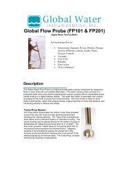
Appendix 1 ID Data Table<br />
NOTE: Bold Shaded values are default for that CPM<br />
1<br />
2<br />
3<br />
4<br />
5<br />
5<br />
6<br />
6<br />
7<br />
7<br />
8<br />
8<br />
9<br />
9<br />
10<br />
10<br />
11<br />
11<br />
12<br />
12<br />
13<br />
13<br />
14<br />
14<br />
15 15<br />
16<br />
16<br />
17<br />
17<br />
18<br />
18<br />
19<br />
19<br />
20<br />
21<br />
22<br />
23<br />
24<br />
25<br />
1<br />
2<br />
3<br />
4<br />
5<br />
6<br />
7<br />
8<br />
9<br />
10<br />
11<br />
12<br />
13<br />
14<br />
15<br />
16<br />
17<br />
18<br />
19<br />
20<br />
21<br />
22<br />
23<br />
24<br />
25<br />
26<br />
27<br />
28<br />
29<br />
1<br />
1.5<br />
2<br />
2.5<br />
3<br />
3.5<br />
4<br />
4.5<br />
5<br />
5.5<br />
6<br />
6.5<br />
7<br />
7.5<br />
8<br />
8.5<br />
9<br />
9.5<br />
10.5<br />
11<br />
11.5<br />
12<br />
12.5<br />
13<br />
13.5<br />
14<br />
14.5<br />
15<br />
10<br />
1<br />
1.2<br />
1.4<br />
1.6<br />
1.8<br />
2<br />
2.2<br />
2.4<br />
2.6<br />
2.8<br />
3<br />
3.2<br />
3.4<br />
3.6<br />
3.8<br />
4<br />
4.2<br />
4.4<br />
4.6<br />
4.8<br />
5<br />
1<br />
1.2<br />
1.4<br />
1.6<br />
1.8<br />
2<br />
2.2<br />
2.4<br />
2.6<br />
2.8<br />
3<br />
3.2<br />
3.4<br />
3.6<br />
3.8<br />
4<br />
4.2<br />
4.4<br />
4.6<br />
4.8<br />
5<br />
5.2<br />
5.4<br />
5.6<br />
5.8<br />
6<br />
6.2<br />
6.4<br />
6.6<br />
6.8<br />
7<br />
11<br />
10.8<br />
10.6<br />
10.4<br />
10.2<br />
10<br />
9.8<br />
9.6<br />
9.4<br />
9.2<br />
9<br />
8.8<br />
8.6<br />
8.4<br />
8.2<br />
8<br />
7.8<br />
7.6<br />
7.4<br />
7.2<br />
7<br />
6.8<br />
6.6<br />
6.4<br />
6.2<br />
6<br />
5<br />
5.8<br />
5.6<br />
5.4<br />
5.2<br />
9<br />
8.8<br />
8.6<br />
8.4<br />
8.2<br />
8<br />
7.8<br />
7.6<br />
7.4<br />
7.2<br />
7<br />
6.8<br />
6.6<br />
6.4<br />
6.2<br />
6<br />
5<br />
5.8<br />
5.6<br />
5.4<br />
5.2<br />
19<br />
18.5<br />
18<br />
17.5<br />
17<br />
16.5<br />
16<br />
15.5<br />
15<br />
14.5<br />
14<br />
13.5<br />
13<br />
12.5<br />
12<br />
11.5<br />
11<br />
10.5<br />
9.5<br />
9<br />
8.5<br />
8<br />
7.5<br />
7<br />
6.5<br />
6<br />
5.5<br />
5<br />
10<br />
14<br />
13.5<br />
13<br />
12.5<br />
12<br />
11.5<br />
11<br />
10.5<br />
9.5<br />
9<br />
8.5<br />
8<br />
7.5<br />
7<br />
6.5<br />
6<br />
5.5<br />
5<br />
10<br />
30<br />
31<br />
32<br />
33<br />
34<br />
35<br />
36<br />
37<br />
38<br />
39<br />
40<br />
1<br />
2<br />
3<br />
4<br />
5<br />
6<br />
7<br />
8<br />
9<br />
10<br />
11<br />
12<br />
13<br />
14<br />
15<br />
16<br />
17<br />
18<br />
19<br />
20<br />
21<br />
22<br />
23<br />
24<br />
25<br />
26<br />
27<br />
28<br />
29<br />
30<br />
31<br />
32<br />
33<br />
34<br />
35<br />
36<br />
37<br />
38<br />
39<br />
40<br />
59<br />
58<br />
57<br />
56<br />
55<br />
54<br />
53<br />
52<br />
52<br />
50<br />
49<br />
48<br />
47<br />
46<br />
45<br />
44<br />
43<br />
42<br />
41<br />
40<br />
39<br />
38<br />
37<br />
36<br />
35<br />
34<br />
33<br />
32<br />
31<br />
30<br />
29<br />
29<br />
28<br />
28<br />
27<br />
27<br />
26<br />
26<br />
25<br />
25<br />
24<br />
24<br />
23<br />
23<br />
22<br />
22<br />
21<br />
21<br />
20<br />
20<br />
41<br />
42<br />
43<br />
44<br />
45<br />
46<br />
47<br />
48<br />
49<br />
50<br />
51<br />
52<br />
53<br />
54<br />
55<br />
56<br />
57<br />
58<br />
59<br />
60<br />
61<br />
62<br />
63<br />
64<br />
65<br />
66<br />
67<br />
68<br />
69<br />
70<br />
71<br />
72<br />
73<br />
74<br />
75<br />
76<br />
77<br />
78<br />
79<br />
80<br />
81<br />
82<br />
83<br />
84<br />
85<br />
86<br />
87<br />
88<br />
89<br />
90<br />
91<br />
92<br />
93<br />
94<br />
95<br />
96<br />
97<br />
98<br />
99<br />
100<br />
101<br />
102<br />
103<br />
104<br />
105<br />
106<br />
107<br />
108<br />
109<br />
110<br />
111<br />
112<br />
113<br />
114<br />
115<br />
116<br />
117<br />
118<br />
119<br />
120<br />
121<br />
122<br />
123<br />
124<br />
125<br />
126<br />
127<br />
128<br />
129<br />
130<br />
131<br />
132<br />
134<br />
133<br />
135<br />
136<br />
137<br />
138<br />
139<br />
140<br />
141<br />
142<br />
143<br />
144<br />
145<br />
146<br />
147<br />
148<br />
149<br />
150<br />
151<br />
152<br />
153<br />
154<br />
155<br />
156<br />
157<br />
158<br />
159<br />
160<br />
161<br />
162<br />
163<br />
164<br />
165<br />
CYCLES / min (CPM)<br />
Disch<br />
(sec)<br />
Refill<br />
(sec)<br />
ID ID ID ID ID ID<br />
Disch<br />
(sec)<br />
Refill<br />
(sec)<br />
Disch<br />
(sec)<br />
1<br />
1.5<br />
2<br />
2.5<br />
3<br />
3.5<br />
4<br />
4.5<br />
5<br />
5.5<br />
6<br />
6.5<br />
7<br />
7.5<br />
8<br />
8.5<br />
9<br />
9.5<br />
10<br />
Refill<br />
(sec)<br />
Disch<br />
(sec)<br />
Refill<br />
(sec)<br />
Disch<br />
(sec)<br />
Refill<br />
(sec)<br />
Disch<br />
(sec)<br />
Refill<br />
(sec)<br />
1 / min 2 / min 3 / min 4 / min 5 / min 6 / min
P.O. Box 3726 Ann Arbor, MI 48106-3726 USA<br />
1-800-624-2026 Fax (734) 995-1170<br />
info@qedenv.com www.qedenv.com