Speich Shao and Goldfarb 2005.pdf - Vanderbilt University
Speich Shao and Goldfarb 2005.pdf - Vanderbilt University
Speich Shao and Goldfarb 2005.pdf - Vanderbilt University

Create successful ePaper yourself
Turn your PDF publications into a flip-book with our unique Google optimized e-Paper software.
Mechatronics 15 (2005) 1127–1142<br />
Modeling the human h<strong>and</strong> as it interacts with<br />
a telemanipulation system<br />
John E. <strong>Speich</strong> a, *, Liang <strong>Shao</strong> b , Michael <strong>Goldfarb</strong> b<br />
a Mechanical Engineering, Virginia Commonwealth <strong>University</strong>, Richmond, VA, 23284-3015, United States<br />
b Mechanical Engineering, V<strong>and</strong>erbilt <strong>University</strong>, Nashville, TN 37235-1592, United States<br />
Received 10 November 2004; returned to author for revision 15 April 2005<br />
Abstract<br />
This paper describes the development of a linear lumped-parameter h<strong>and</strong>/arm model for<br />
the operator of a telemanipulation system. The authors previously developed a control<br />
architecture that implements frequency-domain loop-shaping compensators to improve the<br />
transparency or ‘‘feel’’ of a telemanipulation system, <strong>and</strong> a human model is used when simulating<br />
this architecture. Typically, the human is modeled as a second order mass–spring–damper<br />
system. The five-parameter model presented in this paper, however, includes an additional<br />
spring <strong>and</strong> damper to better approximate the dynamics within the specific frequency range for<br />
which compensators will be designed, typically below 20–30 Hz. The model form <strong>and</strong> parameters<br />
were determined from experimental data taken from a telemanipulation system with<br />
a single translational degree-of-freedom. Additional data was taken from a system with three<br />
actuated degrees-of-freedom, <strong>and</strong> a set of model parameters was determined for each direction<br />
of motion. Each set of model parameters presented in this paper is for the specific grip type<br />
<strong>and</strong> h<strong>and</strong>/arm orientation used during interaction with each particular telemanipulation<br />
system, however similar sets of parameters using this human model could be obtained for<br />
interaction with other telemanipulation systems <strong>and</strong> haptic interfaces. A comparison of the<br />
five-parameter model with a two-parameter spring–damper model suggests that in some cases<br />
the use of additional model parameters may not offer a significant improvement.<br />
Ó 2005 Elsevier Ltd. All rights reserved.<br />
* Corresponding author. Tel.: +1 804 827 7036; fax: +1 804 828 4269.<br />
E-mail address: jespeich@vcu.edu (J.E. <strong>Speich</strong>).<br />
0957-4158/$ - see front matter Ó 2005 Elsevier Ltd. All rights reserved.<br />
doi:10.1016/j.mechatronics.2005.06.001
1128 J.E. <strong>Speich</strong> et al. / Mechatronics 15 (2005) 1127–1142<br />
Keywords: Telemanipulation; Human–robot interaction; Human modeling; H<strong>and</strong> model; Finger model<br />
1. Introduction<br />
A general bilateral telemanipulation system, in which a human operator interacts<br />
with an environment through a master–slave telemanipulator pair, is depicted in<br />
Fig. 1. In the figure, V h <strong>and</strong> F h are the velocity <strong>and</strong> force, respectively, associated<br />
with the port of interaction between the operator <strong>and</strong> the telemanipulator, <strong>and</strong> V e<br />
<strong>and</strong> F e are the velocity <strong>and</strong> force, respectively, associated with the port of interaction<br />
between the telemanipulator <strong>and</strong> environment. In a two-channel position-force<br />
architecture, the operator can be modeled as an admittance <strong>and</strong> the environment<br />
as an impedance. The human is modeled as an admittance because he or she comm<strong>and</strong>s<br />
motion to <strong>and</strong> receives force from the master manipulator. As such, the operator<br />
imposes motion on a motion-controlled slave manipulator, which imposes its<br />
endpoint motion on the environment impedance. Motion imposed on the environment<br />
impedance generates a force, which is imposed on a force-controlled master<br />
manipulator, which in turn imposes that force on the admittance of the human.<br />
When developing control architectures for telemanipulation systems, it is often<br />
necessary to use a model of the human operator. The authors previously developed<br />
a modified position-force control architecture that allows the use of frequency-domain<br />
loop-shaping techniques to improve the transparency of a telemanipulation<br />
system [1–4]. Transparency is the extent to which the manipulator system preserves<br />
the ‘‘feel’’ of the environment. Using this architecture, compensators are implemented<br />
to shape the magnitude of the impedance transmitted to the human operator<br />
such that the telemanipulation system is more transparent. These compensators are<br />
designed to address specific frequencies where the transparency improvement is desired.<br />
In order to simulate this control architecture, a model for the human operator<br />
block shown in Fig. 1 is required. Typically, the human is modeled as a three-parameter<br />
mass–spring–damper system [5,6]. This paper presents a five-parameter model<br />
that includes an additional spring <strong>and</strong> damper, which can better approximate the<br />
dynamics of the operator within the specific frequency range for which compensators<br />
are being designed. This frequency range is usually below 20–30 Hz <strong>and</strong> includes the<br />
frequency range of human volitional motion.<br />
This paper describes the development of both a two-parameter human h<strong>and</strong>/arm<br />
model <strong>and</strong> a five-parameter model that characterize interaction with a telemanipulation<br />
system. Experimentally determined model parameters are presented for interac-<br />
Operator<br />
V h<br />
F h<br />
Bilateral<br />
Telemanipulator<br />
System<br />
V e<br />
F e<br />
Environment<br />
Fig. 1. Block diagram representation of a telemanipulation system.
J.E. <strong>Speich</strong> et al. / Mechatronics 15 (2005) 1127–1142 1129<br />
tion with a telemanipulation system with a single translational degree-of-freedom<br />
(DOF) <strong>and</strong> a knob-type grip interface. Additional data <strong>and</strong> model parameters are<br />
presented for a telemanipulation system with three-DOF <strong>and</strong> a pencil-type grip<br />
interface.<br />
2. Previous work<br />
The human arm, h<strong>and</strong>, <strong>and</strong> fingers are an amazingly complex system of muscles,<br />
bones, nerves <strong>and</strong> other tissues, which are capable of grasping <strong>and</strong> manipulating objects<br />
with great dexterity. Many researchers in the fields of biology <strong>and</strong> robotics have<br />
paid considerable attention to underst<strong>and</strong>ing <strong>and</strong> developing models of the impedance<br />
characteristics of the human arm <strong>and</strong> h<strong>and</strong> [5,7–12]. In the field of robotics,<br />
this research is usually not as concerned with the complex neuromuscular interactions<br />
within the human arm/h<strong>and</strong>, but rather the development of a simple model that<br />
represents the arm/h<strong>and</strong> dynamics as an input/output relationship [7].<br />
Several researchers have experimentally determined values for the human h<strong>and</strong><br />
impedance as a function of the direction of motion in the horizontal plane <strong>and</strong> as<br />
a function of arm configuration [8–11]. Mussa-Ivaldi et al. [8] delivered small displacements<br />
to the h<strong>and</strong> while a test subject maintained a particular posture. The<br />
force on the h<strong>and</strong> was measured <strong>and</strong> the stiffness was calculated from the force<br />
<strong>and</strong> displacement data. They concluded that the neuromuscular behavior of the<br />
arm is predominately spring-like. Flash <strong>and</strong> Mussa-Ivaldi [9] investigated the interactions<br />
between the geometrical, mechanical, <strong>and</strong> neural factors that determine arm<br />
behavior. They found that the h<strong>and</strong> stiffness is strongly dependent on the arm configuration.<br />
Gomi et al. [12] concluded that experimentally determined human-arm<br />
stiffness values vary greatly between subjects, tasks, experimental apparatuses, <strong>and</strong><br />
perturbation patterns.<br />
Ikeura et al. [13] investigated human-arm characteristics in the context of a<br />
human <strong>and</strong> a robot cooperatively moving an object along a single degree-of-freedom.<br />
In this same context, Rahman et al. [14] developed a second order model in<br />
which the stiffness <strong>and</strong> damping coefficients vary with time <strong>and</strong> the model is updated<br />
in real time. Chou <strong>and</strong> Hannaford [15] built a physical elbow system with the goal of<br />
obtaining mechanical properties as close as possible to those of the human arm.<br />
In the context of teleoperation, Kosuge et al. [5] modeled the human as an impedance<br />
for the purposes of designing a teleoperation control architecture. They<br />
experimentally determined the mass, damping <strong>and</strong> stiffness values for single<br />
degree-of-freedom linear model. Lawrence [6] also suggested modeling the human<br />
as an impedance for the purposes of illustrating a telemanipulation architecture. This<br />
human impedance, z h , is given by the equation:<br />
z h ¼ F h<br />
x h s ¼ m hs 2 þ b h s þ k h<br />
s<br />
ð1Þ<br />
where m h , b h ,<strong>and</strong>k h are the mass, damping <strong>and</strong> stiffness of the human operator; F h<br />
is the force acting on the human; x h is the displacement of the human. Eq. (1)
1130 J.E. <strong>Speich</strong> et al. / Mechatronics 15 (2005) 1127–1142<br />
corresponds to the mass–spring–damper model shown in Fig. 2. Kuchenbecker et al.<br />
[16], used a mass–spring–damper model to characterize the human wrist during haptic<br />
interaction with various grasp forces, <strong>and</strong> Hajian <strong>and</strong> Howe [17] studied the<br />
mechanical impedance of the human finger.<br />
In previous work, the authors [1–3] have used the human model suggested by<br />
Lawrence. The models used by Kosuge et al. [4] <strong>and</strong> Lawrence [5] assumed that<br />
the human has a perfectly rigid grasp on the end-effector of the manipulator, i.e.<br />
the position of the end-effector is the same as the position of the operatorÕs h<strong>and</strong>.<br />
The human interface on the manipulator used by Kosuge et al. was a round h<strong>and</strong>le,<br />
which the human probably grasped with the thumb, at least two fingers <strong>and</strong> part of<br />
the palm. Using this type of grasp, the operator can maintain a very firm grip on the<br />
h<strong>and</strong>le, <strong>and</strong> thus the assumption that the grasp is perfectly rigid is valid for the purpose<br />
of developing a simple model. The single degree-of-freedom manipulator used<br />
in this study has a similar round h<strong>and</strong>le, as shown in Fig. 3; however, the three degree-of-freedom<br />
manipulator used in this research uses a stylus as the human interface,<br />
as shown in Fig. 4. The operator of the three degree-of-freedom system grasps<br />
the stylus as if it were a pencil, using only his or her fingertips. This type of grasp is<br />
x h<br />
F h<br />
M h<br />
k h<br />
b h<br />
Fig. 2. A mass–spring–damper model.<br />
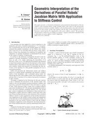
Fig. 3. The single DOF manipulator with the operator grasping the h<strong>and</strong>le overlaid with a five-parameter<br />
h<strong>and</strong>/arm model.
J.E. <strong>Speich</strong> et al. / Mechatronics 15 (2005) 1127–1142 1131<br />
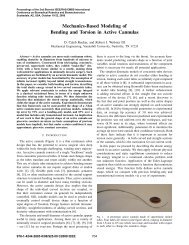
Fig. 4. Photographs of the three-DOF manipulator. In the lower photograph, the operator is holding the<br />
stylus with a pencil-type grasp.<br />
generally much softer than the grasp used on a h<strong>and</strong>le, <strong>and</strong> therefore, a human<br />
model that accounts for this softer interaction is necessary. The h<strong>and</strong>/arm model<br />
developed in this paper does not assume that human has a rigid grasp on the robot,<br />
but rather explicitly models the contact between the human <strong>and</strong> the robot as a soft<br />
contact by including an additional spring <strong>and</strong> damper. This soft-contact model better<br />
approximates the interaction between the human <strong>and</strong> the robotic interface when<br />
the human uses a pencil-type grasp. The model developed in this paper is more general<br />
than the model used by Kosuge <strong>and</strong> Lawrence <strong>and</strong> the model form is suitable for<br />
both for both rigid <strong>and</strong> soft-contact grasps.<br />
3. Hardware<br />
Two different telemanipulation systems were used in this study, a single DOF system<br />
<strong>and</strong> a three-DOF system. The single DOF telemanipulator interface shown in
1132 J.E. <strong>Speich</strong> et al. / Mechatronics 15 (2005) 1127–1142<br />
Fig. 3 was used to collect the data used to develop the h<strong>and</strong>/arm model. This device<br />
uses a N12M4T Kollmorgen DC servomotor, with an internal tachometer to measure<br />
velocity <strong>and</strong> an aligned potentiometer to measure position. A gear-rack with linear<br />
ball slide is used to transform the revolute motion of the servomotor into a linear<br />
translation. The human interface is a h<strong>and</strong>le mounted on the end of a cantilever<br />
beam, which is fixed to the translating rack. The knob similar is to those used on levers<br />
found on some types of industrial equipment. The cantilever is equipped with<br />
strain gages to measure the force acting on the h<strong>and</strong>le. The range of motion of<br />
the telemanipulator interface is approximately 10 cm.<br />
The master manipulator shown in Fig. 4 has three actuated DOF. It has an<br />
approximately cubic workspace with 20 cm sides, <strong>and</strong> its end-effector is a stylus,<br />
which is controlled by the human operator. The stylus is connected to the manipulator<br />
using a universal joint, which provides an additional non-actuated three-DOF.<br />
A six-axis ATI Mini-40 force–torque sensor (ATI Industrial Automation, Inc.) (not<br />
shown) is used to measure forces near the end-effector of the master manipulator.<br />
4. Experimental methods<br />
To develop the human h<strong>and</strong>/arm model, a series of tests was conducted with the<br />
single DOF manipulator. In each test, the operator grasped the end-effector of the<br />
manipulator as shown in Fig. 3, as if he or she wanted to use it to manipulate an<br />
object. Meanwhile, the manipulator was used to apply a time-varying force to the<br />
operatorÕs h<strong>and</strong> for a duration of 50 s. The test subjects were asked to not resist<br />
the motion of the h<strong>and</strong>le <strong>and</strong> to maintain a consistent grasp. The applied force<br />
was comm<strong>and</strong>ed as a b<strong>and</strong>-limited white noise signal with a magnitude that spanned<br />
the force range of the manipulator. Fig. 5 shows a typical power spectrum magnitude<br />
of the force input to the single DOF device, which falls below 0 dB between 20 <strong>and</strong><br />
30<br />
20<br />
Magnitude (dB)<br />
10<br />
0<br />
-10<br />
-20<br />
-30<br />
10 -1 10 0 10 1 10 2<br />
Frequency (Hz)<br />
Fig. 5. Typical power spectrum (dB) of the force input to the single DOF device.
J.E. <strong>Speich</strong> et al. / Mechatronics 15 (2005) 1127–1142 1133<br />
Displacement (mm)<br />
20<br />
15<br />
10<br />
5<br />
0<br />
-5<br />
-10<br />
-15<br />
-20<br />
-25<br />
-30<br />
0 1 2 3 4 5 6 7 8 9 10<br />
Time (s)<br />
Fig. 6. Typical output displacement of the single DOF device.<br />
30 Hz. Data for frequencies above 30 Hz was not considered, <strong>and</strong> may be unreliable<br />
because the input force b<strong>and</strong>width may have been insufficient to excite the h<strong>and</strong><br />
dynamics at these frequencies. The applied force <strong>and</strong> position of the manipulator<br />
were measured at the endpoint using a sampling frequency of 1000 Hz. The rootmean-square<br />
(RMS) amplitude of the force input was selected to be on the order<br />
of a Newton, which resulted in motion perturbations with RMS amplitudes on<br />
the order of a few millimeters. A typical data set indicating the amplitude of movement<br />
during the experimental characterization of arm dynamics is shown in Fig. 6.<br />
The linear modeling techniques used in this paper are largely justified by the relatively<br />
small motions used to characterize arm dynamics. The fairly small motions utilized<br />
in the dynamic characterization are appropriate for the intended application<br />
(i.e., stability analysis within a haptic or teleoperative feedback loop), but clearly<br />
the accuracy of the model will be decreased as the amplitude of arm motion becomes<br />
larger. Five test subjects completed five tests each, which yielded a total of 25 data<br />
sets. MATLAB Real-Time Windows Target (The MathWorks, Inc.) was used to<br />
implement the control algorithm for these experiments.<br />
5. Data processing<br />
The frequency response of the human-arm dynamics from force output to motion<br />
input was obtained through the following relationship:<br />
HðjxÞ ¼ X ðjxÞ<br />
F ðjxÞ ¼ U fxðjxÞ<br />
ð2Þ<br />
U ff ðjxÞ<br />
where U fx (jx) is the cross-power spectral density between the force input <strong>and</strong> the displacement<br />
output, <strong>and</strong> U ff (jx) is the power spectral density of the force input. This<br />
relationship can be derived by combining the convolution theorem with the
1134 J.E. <strong>Speich</strong> et al. / Mechatronics 15 (2005) 1127–1142<br />
Fig. 7. The spring–damper model of Eq. (3) (dashed lines) <strong>and</strong> the five-parameter h<strong>and</strong>/arm model of Eq.<br />
(10) (solid lines) fit to the average force-position data from the single DOF manipulator.<br />
mathematical definitions of convolution <strong>and</strong> correlation. This approach to frequency-based<br />
identification of the human-arm dynamics was implemented through<br />
the spectrum function in MATLAB (The MathWorks, Inc.).<br />
The processed data from the tests is presented in Fig. 7, which shows the average<br />
magnitude <strong>and</strong> phase for all 25 tests. The fact that the magnitude rolls off at an average<br />
slope of 20 dB/decade within the 1–10 Hz b<strong>and</strong>width indicates that an appropriate<br />
human-arm model would have a relative order of one. Further, in the same<br />
frequency range of interest, the phase appears to drop to about 90° before higher<br />
order dynamics appear to generate additional influence. This would also suggest<br />
using a model with a relative order of one. Based on these observations, the following<br />
mathematical models were developed for human h<strong>and</strong> <strong>and</strong> arm.<br />
6. A two-parameter human model<br />
The dynamics of the human arm <strong>and</strong> h<strong>and</strong> can be represented by the spring <strong>and</strong><br />
damper model shown in Fig. 8. In this model, the upper body of the human operator<br />
is considered to be fixed. The interaction force between the master manipulator <strong>and</strong><br />
F h<br />
x m<br />
b a<br />
k a<br />
Fig. 8. The spring–damper human arm model.
the human is labeled F h , <strong>and</strong> the motion of the endpoint of the manipulator is labeled<br />
x m . The stiffness of the human is represented by k a <strong>and</strong> the damping of the<br />
human is represented by b a . The transfer function between the applied force, F h ,<br />
<strong>and</strong> the resulting motion, x m , can be written:<br />
x h 1<br />
¼<br />
ð3Þ<br />
F h b a s þ k a<br />
This model has a relative order of one, which correlates with the data presented in<br />
Fig. 7. Parameters for the model were determined by fitting Eq. (3) to the experimental<br />
data as shown in Fig. 7. The fit was performed using the least-squares curve fitting<br />
function lsqcurvefit in MATLAB. The resulting parameters were:<br />
b a ¼ 3.6 N s=m<br />
k a ¼ 40 N=m<br />
J.E. <strong>Speich</strong> et al. / Mechatronics 15 (2005) 1127–1142 1135<br />
This model captures the overall trend of the experimental data, however, the distinct<br />
change in the slope of the magnitude plot between 2 <strong>and</strong> 3 Hz <strong>and</strong> the dip<br />
between 2 <strong>and</strong> 6 Hz in the phase plot of the experimental data suggest the development<br />
of a more representative model.<br />
7. A five-parameter human h<strong>and</strong>/arm model<br />
The dynamics of the human arm <strong>and</strong> h<strong>and</strong> can also be represented by the lumpedparameter<br />
model shown in Fig. 9. The same five-parameter model is overlaid on the<br />
photograph of the single DOF manipulator <strong>and</strong> the human operator in Fig. 3. Asin<br />
the previous model, the upper body of the human operator is considered to be fixed.<br />
The motion of the human is represented by x h , <strong>and</strong> its mass is represented by <strong>and</strong> m h .<br />
The interaction force between the master manipulator <strong>and</strong> the human is labeled F h ,<br />
<strong>and</strong> the motion of the endpoint of the manipulator is labeled x m . The stiffness of the<br />
human is represented by k 1 <strong>and</strong> k 2 , <strong>and</strong> the damping of the human is represented by<br />
b 1 <strong>and</strong> b 2 .<br />
The equation of motion for the mass of the human, m h , can be written:<br />
m h €x h ¼ k 2 x h b 2 _x h s þ k 1 ðx m x h Þþb 1 ð_x m _x h Þ ð4Þ<br />
x m x h<br />
k k<br />
F 1<br />
2<br />
h<br />
M h<br />
b 1<br />
b 2<br />
Fig. 9. The five-parameter human h<strong>and</strong>/arm model.
1136 J.E. <strong>Speich</strong> et al. / Mechatronics 15 (2005) 1127–1142<br />
Eq. (4) can be rewritten in Laplace notation as<br />
m h x h s 2 ¼ k 2 x h b 2 x h s þ k 1 ðx m x h Þþb 1 ðx m x h Þs ð5Þ<br />
where s is the Laplace variable. Solving Eq. (5) for the displacement of the human,<br />
x h , gives the equation:<br />
ðk 1 þ b 1 sÞx m<br />
x h ¼<br />
ð6Þ<br />
m h s 2 þðb 2 þ b 1 Þs þðk 2 þ k 1 Þ<br />
The force acting between the manipulator <strong>and</strong> the h<strong>and</strong>, F h , is the sum of the<br />
forces in stiffness element k 1 <strong>and</strong> damping element b 1 , which can be expressed as<br />
F h ¼ k 1 ðx m x h Þþb 1 ð_x m _x h Þ ð7Þ<br />
Eq. (7) can be rewritten in Laplacian notation <strong>and</strong> simplified to give the equation:<br />
F h ¼ðk 1 þ b 1 sÞðx m x h Þ ð8Þ<br />
Substituting the expression for x h in Eq. (6) into Eq. (8) gives the following expression<br />
for F h :<br />
<br />
<br />
ðk 1 þ b 1 sÞx m<br />
F h ¼ðk 1 þ b 1 sÞ x m<br />
ð9Þ<br />
m h s 2 þðb 2 þ b 1 Þs þðk 2 þ k 1 Þ<br />
Eq. (9) can be rearranged to give the following equation for the ratio of the position<br />
of the manipulator/human contact point to the force acting on the human:<br />
x m<br />
m h s 2 þðb 2 þ b 1 Þs þðk 2 þ k 1 Þ<br />
¼<br />
ð10Þ<br />
F h m h b 1 s 3 þðm h k 1 þ b 1 b 2 Þs 2 þðk 1 b 2 þ b 1 k 2 Þs þ k 2 k 1<br />
This transfer function between the applied force <strong>and</strong> the resulting motion has a relative<br />
order of one, which correlates with the data presented in Fig. 7.<br />
The ratio of the velocity of the manipulator/human contact point, V m , to the force<br />
on the human, F h , is the admittance of the human, which can be written as<br />
Y h ¼ V m<br />
½m h s 2 þðb 2 þ b 1 Þs þðk 2 þ k 1 ÞŠs<br />
¼<br />
ð11Þ<br />
F h m h b 1 s 3 þðm h k 1 þ b 1 b 2 Þs 2 þðk 1 b 2 þ b 1 k 2 Þs þ k 2 k 1<br />
The parameters b 1 , b 2 , k 1 , k 2 , <strong>and</strong> m h of the h<strong>and</strong>/arm model expressed in Eq. (10)<br />
were determined by fitting this equation to the experimental data collected from the<br />
manipulator. The fit was performed using the least-squares curve fitting function lsqcurvefit<br />
in MATLAB.<br />
The steady state gain, a, for the force-position transfer function in Eq. (10) can be<br />
written:<br />
a ¼ k 1 þ k 2<br />
k 1 k 2<br />
ð12Þ<br />
This equation can be rearranged to give the following expression for the stiffness k 2<br />
in terms of the stiffness k 1 <strong>and</strong> the steady state gain:<br />
k 2 ¼ k 1<br />
ak 1 1<br />
ð13Þ
J.E. <strong>Speich</strong> et al. / Mechatronics 15 (2005) 1127–1142 1137<br />
The magnitude plot in Fig. 7 has a steady state gain, a, of approximately 32 dB,<br />
which corresponds to a gain of 0.025 m/N. Using this value for a <strong>and</strong> Eq. (13),<br />
the remaining parameters b 1 , b 2 , k 1 <strong>and</strong> m h were selected such that the plot for<br />
Eq. (10) fit the data in Fig. 7. The resulting parameter for the human h<strong>and</strong>/arm<br />
model were:<br />
b 1 ¼ 4.5 N s=m<br />
b 2 ¼ 7.9 N s=m<br />
k 1 ¼ 48.8 N=m<br />
k 2 ¼ 375 N=m<br />
m h ¼ 1.46 kg<br />
Notice in Fig. 7 that the five-parameter h<strong>and</strong>/arm model (solid lines) is a better<br />
approximation of the experimental data than the two-parameter spring–<br />
damper model (dashed lines) in both magnitude <strong>and</strong> phase, especially between 2<br />
<strong>and</strong> 6 Hz.<br />
8. A comparison with other models<br />
This section presents a comparison of the five-parameter model developed in this<br />
paper with the experimental models presented by Kosuge et al. [5] <strong>and</strong> Tsuji et al.<br />
[10] <strong>and</strong> the model suggested by Lawrence [6]. The models used by Kosuge, Tsuji<br />
<strong>and</strong> Lawrence can all be expressed using Eq. (1).<br />
Kosuge et al. [1] experimentally found the following human-arm parameters:<br />
b h ¼ 17 N s=m<br />
k h ¼ 243 N=m<br />
m h ¼ 11.6 kg<br />
Tsuji et al. [10] found values for the stiffness <strong>and</strong> damping for a human h<strong>and</strong><br />
impedance model as a function of the direction of motion in the horizontal plane<br />
<strong>and</strong> as a function of arm configuration. The following values for the stiffness, k h ,<br />
<strong>and</strong> the damping, b h , are rough estimates taken from figures presented by Tsuji<br />
for arm motion perpendicular to the operator in the distal arm position:<br />
b h 20 N s=m<br />
k h 300 N=m<br />
m h ¼ 3.25 kg<br />
Lawrence [6] suggested using the following human-arm parameters:<br />
b h ¼ 175 N s=m<br />
k h ¼ 175 N=m<br />
m h ¼ 17.5 kg
1138 J.E. <strong>Speich</strong> et al. / Mechatronics 15 (2005) 1127–1142<br />
which according to Lawrence, correspond to an operator with the manipulator<br />
firmly in h<strong>and</strong>, but with very little arm tension.<br />
The human impedance models of Kosuge, Tsuji <strong>and</strong> Lawrence can be expressed<br />
using Eq. (1), which can be written as the ratio of the position of the human, x h ,<br />
to the force acting on the human, F h , given by the equation:<br />
x h 1<br />
¼<br />
ð14Þ<br />
F h m h s 2 þ b h s þ k h<br />
Using Eqs. (10) <strong>and</strong> (14), Fig. 10 presents a comparison of the models used by<br />
Kosuge et al. (dash-dot lines), Tsuji et al. (dotted lines), Lawrence (dashed lines)<br />
<strong>and</strong> the five-parameter h<strong>and</strong>/arm model developed in this paper (solid lines). At<br />
low frequencies, the magnitude plots differ primarily by a scaling gain. At frequencies<br />
above approximately 1 Hz, the magnitude plots of the models used by Kosuge,<br />
Tsuji <strong>and</strong> Lawrence all drop off at 40 dB per decade, which indicates that these<br />
models have a relative order of two. In contrast, the h<strong>and</strong>/arm model developed<br />
in this paper has a relative order of one. The magnitude plot for the h<strong>and</strong>/arm model<br />
drops off at 20 dB per decade, which better matches the experimental data for this<br />
manipulator. The phase plots of the models used by Kosuge, Tsuji <strong>and</strong> Lawrence all<br />
approach 180°, i.e., they have a relative order of two. In contrast, the phase plot of<br />
the h<strong>and</strong>/arm model approaches 90° <strong>and</strong> has a relative order of one, which better<br />
matches the experimental data from this manipulator. The human-arm models<br />
which have relative orders of two consider the mass of the manipulator <strong>and</strong> the mass<br />
of the human arm to be lumped together; however, the five-parameter model has a<br />
relative order of one <strong>and</strong> considers the mass of the human separately. Considering<br />
the human mass separately provides a model that better matches the data from this<br />
manipulator <strong>and</strong> models the dynamics of the interaction between the mass of the<br />
robot <strong>and</strong> the mass of the human.<br />
Magnitude<br />
0<br />
-50<br />
-100<br />
-150<br />
10 -2 10 0 10 2<br />
0<br />
Phase<br />
-100<br />
-200<br />
10 -2 10 0 10 2<br />
Frequency<br />
Fig. 10. Comparison of the human admittance models of Kosuge (dash-dot lines), Tsuji (dotted lines),<br />
Lawrence (dashed lines) <strong>and</strong> the five-parameter h<strong>and</strong>/arm model developed in this paper (solid lines).
J.E. <strong>Speich</strong> et al. / Mechatronics 15 (2005) 1127–1142 1139<br />
9. Modeling human interaction with the three-DOF manipulator<br />
Model parameters for human interaction with the three-DOF manipulator shown<br />
in Fig. 4 were determined in a similar manner. Five test subjects who were familiar<br />
with the device were used, <strong>and</strong> each subject completed five tests. To begin each test,<br />
the subject grasped the stylus of the manipulator with a pencil-type grip, as if he or<br />
she wanted to use it to manipulate an object by pushing it with a pencil. The test subject<br />
was seated in front of the manipulator with their elbow bent at an angle of<br />
approximately 90°. Next, the operator moved the stylus about the workspace of<br />
the manipulator, as if he or she was using it to manipulate an object. Then, the operator<br />
stopped near the center of the workspace, <strong>and</strong> the manipulator was used to apply<br />
time-varying forces to the operatorÕs h<strong>and</strong> for 10 s. The test subject was asked to<br />
not resist the motion of the stylus <strong>and</strong> to maintain a consistent grip on the stylus. The<br />
forces were applied in each of the three-DOF simultaneously for 10 s, <strong>and</strong> were comm<strong>and</strong>ed<br />
as b<strong>and</strong>-limited white noise signals with magnitudes that spanned the force<br />
range of the manipulator (10 N). The applied forces <strong>and</strong> position coordinates of the<br />
manipulator were measured at the endpoint using a sampling frequency of 2000 Hz.<br />
Data from the three-DOF manipulator were processed as described in Section 5.<br />
This data is presented in Fig. 11, which shows separate magnitude plots for each of<br />
the three-DOF. These plots show the average magnitude from the series of 25 tests.<br />
Fig. 11. Eq. (10) fit to the average force-position data for the x (top), y (middle) <strong>and</strong> z (bottom) directions.
1140 J.E. <strong>Speich</strong> et al. / Mechatronics 15 (2005) 1127–1142<br />
Table 1<br />
Human model parameters for the three-DOF telemanipulation system<br />
Direction Parameters<br />
b 1 (N s/m) k 1 (N/m) m h (kg) b 2 (N s/m) k 2 (N/m)<br />
X 12.9 122 0.85 12.9 330<br />
Y 9.20 108 4.03 47.6 104<br />
Z 17.6 81.4 0.68 13.5 13.0<br />
The positive x direction is used to define motion toward the human operator, while<br />
the positive y direction represents motion vertically upward, <strong>and</strong> the positive z direction<br />
corresponds to motion to the operatorÕs left. Although movements along the<br />
three translational DOF are presumably coupled to some extent, they were assumed<br />
to be decoupled, <strong>and</strong> different model parameters were determined for each DOF.<br />
Separate human interaction models were necessary because separate control loops<br />
were designed for each DOF of the manipulator.<br />
The magnitude plots in Fig. 11 roll off at slopes of approximately 20 dB/decade<br />
within the 1–10 Hz b<strong>and</strong>width, which suggest that an appropriate human-arm model<br />
would have a relative order of one, like the five-parameter mathematical model<br />
developed in Section 7. This model was fit to the experimental data in Fig. 11 using<br />
Eq. (10). Only the data below 30 Hz was used to determine the fit, <strong>and</strong> Eq. (13) was<br />
used to constrain the low frequency (steady state) gain to match the data. Three distinct<br />
sets of model parameters were determined, one for each direction of human motion,<br />
as listed in Table 1.<br />
Gomi et al. [12] concluded that experimentally determined human-arm stiffness<br />
values vary greatly between subjects, tasks, experimental apparatuses, <strong>and</strong> perturbation<br />
patterns. Flash <strong>and</strong> Mussa-Ivaldi [9] investigated the interactions between the<br />
geometrical, mechanical, <strong>and</strong> neural factors that determine arm behavior. They found<br />
that the h<strong>and</strong> stiffness is strongly dependent on the arm configuration. Thus, the model<br />
parameters presented in this paper are for the specific grip type <strong>and</strong> human h<strong>and</strong>/<br />
arm orientation used during interaction with each of these particular telemanipulation<br />
systems, however similar sets of parameters for this human model could be obtained<br />
for interaction with other telemanipulation systems <strong>and</strong> haptic interfaces.<br />
The human model developed in this section is being used by the authors to examine<br />
the stability robustness <strong>and</strong> transparency of a scaled telemanipulation system<br />
that uses the three-DOF manipulator as the human interface [1–3,18]. For this<br />
telemanipulation system, the frequency b<strong>and</strong> between 0.5 Hz <strong>and</strong> 10 Hz is of primary<br />
interest when assessing the system transparency. Therefore, the parameters for the<br />
human model were selected to best fit the experimental data in the frequency range<br />
between 0.5 <strong>and</strong> 10 Hz.<br />
10. Conclusions<br />
The authors have developed a model for the human arm <strong>and</strong> h<strong>and</strong> as they interact<br />
with a telemanipulation system <strong>and</strong> experimentally determined the model parameters
J.E. <strong>Speich</strong> et al. / Mechatronics 15 (2005) 1127–1142 1141<br />
for a single DOF <strong>and</strong> a three-DOF telemanipulation system. The model adds an<br />
additional spring <strong>and</strong> damper to the mass–spring–damper model typically used to<br />
represent a human <strong>and</strong> better approximates the dynamics of the human while interacting<br />
with the manipulators used in this study. This model can be used to design<br />
<strong>and</strong> analyze control architectures for telemanipulation systems <strong>and</strong> haptic interfaces<br />
[1–4].<br />
Acknowledgments<br />
Support for this work was provided by NASA Grant No. NGT 852857. The<br />
authors gratefully acknowledge this support. The human interaction model for the<br />
single DOF manipulator was presented at the 2001 ASME International Mechanical<br />
Engineering Congress <strong>and</strong> Exposition [18].<br />
References<br />
[1] Fite KB, <strong>Speich</strong> JE, <strong>Goldfarb</strong> M. On the use of two channels for bilateral telemanipulation. In:<br />
Proceedings of the ASME international mechanical engineering congress <strong>and</strong> exposition. 2000.<br />
p. 1231–8.<br />
[2] <strong>Speich</strong> JE, Fite KB, <strong>Goldfarb</strong> M. A method for simultaneously increasing transparency <strong>and</strong> stability<br />
robustness in bilateral telemanipulation. In: Proceedings of the IEEE international conference on<br />
robotics <strong>and</strong> automation. 2000. p. 2671–6.<br />
[3] Fite KB, <strong>Goldfarb</strong> M, <strong>Speich</strong> JE. Transparency <strong>and</strong> stability robustness in two-channel bilateral<br />
telemanipulation. ASME J Dyn Syst Measurement Control 2001;123(5):400–7.<br />
[4] <strong>Speich</strong> JE, <strong>Goldfarb</strong> M. Implementing loop-shaping compensators to increase the transparency<br />
b<strong>and</strong>width of a scaled telemanipulation system. In: Proceedings of the IEEE international conference<br />
on robotics <strong>and</strong> automation. 2002.<br />
[5] Kosuge K, Fujisawa Y, Fukuda T. Control of mechanical system with man–machine interaction. In:<br />
Proceedings of the IEEE/RSJ international conference on intelligent robots <strong>and</strong> systems. 1992.<br />
p. 87–92.<br />
[6] Lawrence DA. Stability <strong>and</strong> transparency in bilateral telemanipulation. IEEE Trans Robot Automat<br />
1993;9(5):624–37.<br />
[7] Kazerooni H. Human–robot interaction via the transfer of power <strong>and</strong> information signals. IEEE<br />
Trans Syst Man Cybern 1990;20(2):450–63.<br />
[8] Mussa-Ivaldi F, Hogan N, Bizzi E. Neural, mechanical, <strong>and</strong> geometric factors subserving arm posture<br />
in humans. J Neurosci 1985;5(10):2732–43.<br />
[9] Flash T, Mussa-Ivaldi F. Human arm stiffness characteristics during the maintenance of posture. Exp<br />
Brain Res 1990;82:315–26.<br />
[10] Tsuji T, Goto K, Moritani M, Kaneko M, Morasso P. Spatial characteristics of human h<strong>and</strong><br />
impedance in multi-joint arm movements. In: Proceedings of the IEEE/RSJ/GI international<br />
conference on intelligent robots <strong>and</strong> systems. 1994. p. 423–30.<br />
[11] Dolan JM, Friedman MB, Nagurka ML. Dynamic <strong>and</strong> loaded impedance components in the<br />
maintenance of human arm posture. IEEE Trans Syst Man Cybern 1993;23(3):698–709.<br />
[12] Gomi H, Koike Y, Kawato M. Human h<strong>and</strong> stiffness during discrete point-to-point multi-joint<br />
movement. In: Proceedings of the IEEE international conference on engineering in medicine <strong>and</strong><br />
biology society. 1992. p. 1628–9.<br />
[13] Ikeura R, Monden H, Inooka H. Cooperative motion control of a robot <strong>and</strong> a human. In:<br />
Proceedings of the IEEE international workshop on robot <strong>and</strong> human communication. 1994.<br />
p. 112–7.
1142 J.E. <strong>Speich</strong> et al. / Mechatronics 15 (2005) 1127–1142<br />
[14] Rahman MM, Ikeura R, Mizutani K. Investigating the impedance characteristics of human arm for<br />
development of robots to cooperate with human operators. In: Proceedings of the IEEE international<br />
conference on systems, man <strong>and</strong> cybernetics. 1999. p. 676–81.<br />
[15] Chou C, Hannaford B. Study of human forearm posture maintenance with a physiologically based<br />
robotic arm <strong>and</strong> spinal level neural controller. Biol Cybern 1997;76:285–98.<br />
[16] Kuchenbecker KJ, Park JG, Niemeyer G. Characterizing the human wrist for improved haptic<br />
interaction. In: Proceedings of the ASME international mechanical engineering congress <strong>and</strong><br />
exposition. 2003.<br />
[17] Hajian AZ, Howe RD. Identification of the mechanical impedance at the human finger tip. ASME J<br />
Biomech Eng 1997;119(1):109–14.<br />
[18] <strong>Speich</strong> JE, <strong>Shao</strong> L, <strong>Goldfarb</strong> M. An experimental h<strong>and</strong>/arm model for human interaction with a<br />
telemanipulation system. In: Proceedings of the ASME international mechanical engineering congress<br />
<strong>and</strong> exposition. 2001.