Ceramics - Ankersmid
Ceramics - Ankersmid
Ceramics - Ankersmid

Create successful ePaper yourself
Turn your PDF publications into a flip-book with our unique Google optimized e-Paper software.
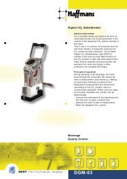
<strong>Ceramics</strong><br />
Debinding<br />
Sintering<br />
Firing<br />
Decorating<br />
Laboratory<br />
www.nabertherm.com<br />
Made<br />
in<br />
Germany
Made in Germany<br />
With over 300 employees, Nabertherm has developed and produced industrial furnaces in many fields for over<br />
50 years. 150,000 customers in all countries of the world are part of the company`s success story. A wide range<br />
of standard furnaces and a high value added of skilled labour in our factory provide for short delivery times.<br />
Experienced sales partners or own sales companies in key countries assure for individual quotes and after sales<br />
service tailored to the needs of our customers.<br />
Setting Standards in Quality and Reliability<br />
From a wide range of standard furnaces up to state-of-the-art sintering plants including integrated afterburning<br />
systems, Nabertherm can provide it all. With customised fully-fledged heat treatment systems technology, even<br />
complicated production processes can be solved. The innovative Nabertherm control and automation technology<br />
assures the professional monitoring, control and documentation of debinding, firing and sintering processes.<br />
Sophisticated technical details like our concept of freely radiating heating elements on ceramic support tubes which<br />
provide for not only a perfect temperature distribution and energy efficiency but also for a long service life are the<br />
key competitive edge.<br />
World-Wide Sales Network<br />
With our world-wide sales network we are close to every customer in order to provide for the necessary support and<br />
service you need. Reference customers with respective furnaces are also close to you helping you to make the right<br />
decision.<br />
Customer Service and Spare Parts<br />
Our experienced staff members in the service department will help you to solve any problem. Whether on site or with<br />
the help of telecommunications, they will be available for you. For fully-fledged heat treatment plants we recommend<br />
our teleservice via modem anyways. Particularly proud we are upon our world-wide spare parts service. In no time<br />
we will reach you all over the world. If you need an answer for your application, our R&D department will take care of<br />
the respective testing in our laboratory which is equipped with all kind of furnaces.<br />
Experience in other Industry Segments and Applications<br />
Beyond the production of kilns for ceramics processing, Nabertherm offers a wide range of standard furnaces and<br />
and systems for many other industry segments. Please, ask for advice or visit our website. The modular design and<br />
technology of our products will make sure that we can solve most of your problems without expensive modifications.<br />
2
Table of contents<br />
Page<br />
DEBINDING Chamber Furnaces, Eectrically Heated ................ 4<br />
Chamber Air-Circulation Furnaces,<br />
Electrically Heated........................................ 5<br />
Chamber Air-Circulation Furnaces,<br />
Electrically or Gas Heated .............................. 6<br />
Bogie Hearth Air-Circulation Furnaces ................ 7<br />
Retort Furnaces for Debinding under<br />
Vacuum or in a Defined Atmosphere .................. 8<br />
Retort Furnaces for Catalytic Debinding .............. 9<br />
DEBINDING/SINTERING IN A COMBI-FURNACE<br />
Chamber Furnaces with Air Preheating................10<br />
High-Temperature Combi-Furnaces<br />
with Air Preheating ......................................22<br />
SINTERING/FIRING Chamber Kilns ............................................12<br />
Shuttle Kilns ..............................................14<br />
Envelope Kilns ..........................................17<br />
Top-Hat Furnaces ........................................18<br />
High-Temperature Chamber Furnaces ................20<br />
High-Temperature Top-Hat and Elevator Furnaces ..22<br />
High-Temperature Furnaces for Vacuum and<br />
Defined Atmospheres ....................................26<br />
DEBINDING AND SINTERING FURNACES Catalytic Afterburners....................................28<br />
WITH INTEGRATED AFTERBURNING SYSTEMS Thermal Afterburners ....................................28<br />
Atmosphere Control......................................28<br />
Plant Concepts............................................29<br />
DECORATING Infrared Fast-Firing Kilns ................................30<br />
LABORATORY Laboratory Fast-Firing Kilns ............................31<br />
Chamber Kilns with Brick and Fibre Insulation ......32<br />
High-Temperature Furnaces ............................33<br />
Gradient Kilns ............................................34<br />
High-Temperature Furnaces for Vacuum<br />
and Defined Atmospheres ..............................35<br />
Tube Furnaces ............................................36<br />
PROCESS CONTROL AND DOCUMENTATION ..........................................................38<br />
3
DEBINDING<br />
Electrically Heated Chamber Furnaces<br />
N 1000/G<br />
N 150/G<br />
Chamber furnaces N 100/G - N 2200/G<br />
These sturdy chamber furnaces are ideal for simple debinding production processes with low binder<br />
concentration.<br />
Standard Version<br />
Tmax 900 °C<br />
Heating from 5 sides with special positioning of the heating elements for optimum temperature distribution<br />
Heating elements based on support tubes resulting in long service life of the heating wire<br />
Floor heating elements protected by SiC plate providing for level stacking support<br />
High quality wear-free thermocouple, type S<br />
Multi-layer insulation with lightweight refractory bricks and special rear insulation<br />
Side walls and door double walled, side walls made of stainless steel (up to N 300..)<br />
Perforated plate cover made from brushed stainless steel (up to N 300..)<br />
Infinitely variable airinlet, exhaust air in the furnace ceiling (from N 450 designed as flap)<br />
Self-supporting brick ceiling construction, arch-shaped<br />
Removable stand (up to N 300…)<br />
Extras<br />
Customised dimensions<br />
Fan for better control of air in- and outflow<br />
Automatic vapour vent flaps<br />
Catalytic or thermal air cleaning systems<br />
Multizone control for temperature distribution up to +/-5 °C according to DIN 17052<br />
Model Tmax Inner dimensions in mm Volume Outer dimensions in mm Connected Connection Weight<br />
°C w d h in litres W D H power/kW voltage 1 in kg<br />
N 100/ G 900 400 530 460 100 710 1150 1430 7 3-phase 270<br />
N 150/ G 900 450 530 590 150 760 1150 1560 9 3-phase 305<br />
N 200/ G 900 500 530 720 200 810 1150 1690 11 3-phase 345<br />
N 300/ G 900 550 700 780 300 860 1340 1750 15 3-phase 430<br />
N 450/ G 900 600 750 1000 450 1000 1440 1820 20 3-phase 700<br />
N 650/ G 900 600 1100 1000 650 1000 1540 1930 26 3-phase 850<br />
N 1000/ G 900 800 1000 1250 1000 1290 1730 1830 40 3-phase 1680<br />
N 1500/ G 900 900 1200 1400 1500 1390 1930 1990 57 3-phase 2300<br />
N 2200/ G 900 1000 1400 1600 2200 1490 2130 2190 75 3-phase 2800<br />
1<br />
Notes on connection voltages please see page 39<br />
4
Chamber Air - Circulation Furnaces Electrically Heated<br />
N 1700/65 AS in special dimensions<br />
Air-Circulation Furnaces N 120/65 DB - N 500/65 DB<br />
When debinding technical ceramics an optimum temperature distribution during the heating-up phase is essential<br />
to make sure that the charge is not damaged. For many applications air circulation furnaces are the only alternative<br />
because the guided air swirl optimises the temperature uniformity in the furnace chamber. The air-circulation<br />
furnaces N 120/65 DB - N 500/65 DB furnaces are specifically developed for this application.<br />
Standard Version<br />
Horizontal air-circulation for temperature distribution from + 3 K according to DIN 17052<br />
Housing almost gas tight with special door sealing<br />
3 shelves included in the delivery package<br />
Additional rails for extra shelves included<br />
Automatic control of vapour vent flap<br />
Additional alternative for ventilation through ball valve<br />
Protective gas inlet and outlet<br />
N 120/65 DB<br />
Extras<br />
Stainless steel interior housing<br />
Customised dimensions<br />
Hot-gas fan<br />
Inert gas purging<br />
Automatic process control (atmosphere on request)<br />
Tube system for exhaust gas<br />
Catalytic or thermal afterburner<br />
Automatic vapor vent flap as standard<br />
Model Tmax Inner dimensions in mm Volume Outer dimensions in mm Connection Connected max.<br />
°C w d h in litres W D H voltage 1 power/kW sheets<br />
N 120/65 DB 650 450 600 450 120 1030 1290 1500 3-phase 9 11<br />
N 250/65 DB 650 600 750 600 250 1190 1505 1860 3-phase 18 14<br />
N 500/65 DB 650 750 900 750 500 1340 1755 2010 3-phase 27 17<br />
Powerful air circulation motor<br />
1<br />
Notes on connection voltages please see page 39<br />
5
DEBINDING<br />
Chamber Air Circulation Furnaces, Electrically or Gas Heated<br />
N 2000/25 HA electrically heated with<br />
horizontal air supply and observation window<br />
Low temperature air circulation furnaces N 560/25 - N 10000/45<br />
Chamber air-circulation furnaces under normal atmosphere for debinding, drying and preheating.<br />
Loading can take place using stackers, charging or lift trucks.<br />
Standard Version<br />
Temperatures up to 250 or 450 °C<br />
Chamber furnaces available with horizontal (type/HA) or vertical air circulation (type/A)<br />
Indirect electrically or gas heated<br />
Ground-level, no floor insulation<br />
Optimum temperature distribution [according to DIN 17052] of up to ±5 °C<br />
High atmosphere turn-over (controlable)<br />
Furnace size suitable for common charging systems<br />
N 1000/45 HA<br />
Extras<br />
Ground level with floor insulation with or without recesses<br />
Observation window and furnace chamber lighting<br />
Exhaust gas fan and safety equipment for evaporating solvents (design according to EN 1539)<br />
Customised dimensions up to 20,000 litres and charge weights up to 20 tons<br />
Catalytic or thermal afterburners<br />
Model Tmax Inner dimensions in mm Volume Outer dimensions in mm Connected Connected<br />
°C w d h in litres W D H power/kW voltage 1<br />
N 560/ 25.. 250 750 1000 750 560 1070 1680 1070 13.0 3-phase<br />
N 1000/ 25.. 250 1000 1000 1000 1000 1380 1820 1200 17.5 3-phase<br />
N 1500/ 25.. 250 1500 1000 1000 1500 1880 1820 1200 20.5 3-phase<br />
N 1500/ 25..1 250 1000 1500 1000 1500 1380 2320 1200 20.5 3-phase<br />
N 2000/ 25.. 250 1500 1100 1200 2000 1880 1930 1420 20.5 3-phase<br />
N 2000/ 25..1 250 1100 1500 1200 2000 1480 2330 1420 20.5 3-phase<br />
N 4000/ 25.. 250 1500 2200 1200 4000 1880 2830 1420 46.0 3-phase<br />
N 4000/ 25..1 250 2200 1500 1200 4000 2380 2330 1420 46.0 3-phase<br />
N 5600/ 25.. 250 1500 2500 1500 5600 1880 2780 2260 64.5 3-phase<br />
N 6750/ 25.. 250 1500 3000 1500 6750 1880 3280 2260 91.0 3-phase<br />
N 7200/ 25.. 250 2000 1500 2400 7200 2380 2330 2620 91.0 3-phase<br />
N 10000/ 25.. 250 2000 2500 2000 10000 2380 2780 2760 111.0 3-phase<br />
N 560/ 45.. 450 750 1000 750 560 1190 1800 1190 19.0 3-phase<br />
N 1000/ 45.. 450 1000 1000 1000 1000 1500 1940 1320 39.0 3-phase<br />
N 1500/ 45.. 450 1500 1000 1000 1500 2000 1940 1320 39.0 3-phase<br />
N 1500/ 45..1 450 1000 1500 1000 1500 1500 2440 1320 39.0 3-phase<br />
N 2000/ 45.. 450 1500 1100 1200 2000 2000 2050 1540 45.0 3-phase<br />
N 2000/ 45..1 450 1100 1500 1200 2000 1600 2550 1540 45.0 3-phase<br />
N 4000/ 45.. 450 1500 2200 1200 4000 2000 2950 1540 64.0 3-phase<br />
N 4000/ 45..1 450 2200 1500 1200 4000 2500 2450 1540 64.0 3-phase<br />
N 5600/ 45.. 450 1500 2500 1500 5600 2000 2900 2380 90.0 3-phase<br />
N 6750/ 45.. 450 1500 3000 1500 6750 2000 3400 2380 109.0 3-phase<br />
N 7200/ 25.. 450 2000 1500 2400 7200 2500 2550 2740 109.0 3-phase<br />
N 10000/ 45.. 450 2000 2500 2000 10000 2500 2900 2880 135.0 3-phase<br />
1<br />
Notes on connection voltages please see page 39<br />
6
DEBINDING<br />
Bogie Hearth Air-Circulation Furnaces<br />
W 2200/65A<br />
with atmosphere box<br />
Bogie Hearth Air-Circulation Furnaces W 1000/65A - W 10000/85A<br />
Bogie hearth furnaces are recommended especially for debinding heavy loads and/or for charging<br />
outside the furnace. The standard furnace already achieves a particularly good temperature<br />
distribution of up to ± 7 °C.<br />
Standard Version<br />
Temperatures up to 550 or 750 °C<br />
Freely travelling bogie on Tefolan castors<br />
3-side heating from both sides and the bogie<br />
Vertical air circulation with fans in the furnace roof<br />
Extras<br />
Atmosphere box for operation with inert gas<br />
Electro-hydraulic lift door<br />
Air inflow and outflow system<br />
Bogie on rails and/or electrical drive of the bogie<br />
Cooling systems<br />
Multi-zone control for optimising the temperature distribution up to +/- 3 K according to with DIN 17052<br />
Control of vapor vent flaps for quick cooling<br />
Customised dimensions up to 20,000 l furnace volume<br />
Bogie hearth furnace W 2160/S<br />
in customised dimensions with<br />
lift-door and rail operation<br />
Model Tmax Inner dimensions in mm Volume Outer dimensions in mm Connected Connected<br />
°C w d h in litres W D H power/kW voltage 1<br />
W 1000/ 65A 650 800 1600 800 1000 1450 2400 2300 42 3-phase<br />
W 1500/ 65A 650 900 1900 900 1500 1550 2750 2400 58 3-phase<br />
W 2000/ 65A 650 1000 2200 1000 2200 1650 3000 2500 77 3-phase<br />
W 3300/ 65A 650 1000 3300 1000 3300 1650 4000 2500 90 3-phase<br />
W 5000/ 65A 650 1200 3400 1200 5000 1850 4100 2700 110 3-phase<br />
W 7500/ 65A 650 1400 3800 1400 7500 2050 4500 2900 140 3-phase<br />
W 10000/ 65A 650 1600 3900 1600 10000 2250 4600 3100 220 3-phase<br />
W 1000/ 85A 850 800 1600 800 1000 1450 2400 2300 42 3-phase<br />
W 1500/ 85A 850 900 1900 900 1500 1550 2750 2400 58 3-phase<br />
W 2200/ 85A 850 1000 2200 1000 2200 1650 3000 2500 77 3-phase<br />
W 3300/ 85A 850 1000 3300 1000 3300 1650 4000 2500 90 3-phase<br />
W 5000/ 85A 850 1200 3400 1200 5000 1850 4100 2700 110 3-phase<br />
W 7500/ 85A 850 1400 3800 1400 7500 2050 4500 2900 140 3-phase<br />
W 10000/ 85A 850 1600 3900 1600 10000 2250 4600 3100 220 3-phase<br />
1<br />
Notes on connection voltages please see page 39<br />
7
DEBINDING<br />
Retort Furnace for Debinding under Vacuum and in a Defined Atmosphere<br />
Retort Furnaces GLO and V-GLO<br />
The horizontal or vertical retort furnaces are used for debinding ceramics under vacuum or in defined atmosphere up<br />
to 1300 °C. Tailored to the respective process, the following applications can be done:<br />
Thermal debinding and presintering of ceramic and/or metal parts<br />
(e.g. pressing, injection moulding, CIM/MIM)<br />
Pyrolytic decomposition of organic pre-stages (e.g. C resins, Si-C compounds,<br />
fibre composites, fibre reinforced materials CMC/MMC)<br />
Vacuum annealing of dental ceramic intermediates<br />
Surface modification of ceramic products e.g. using forming gas or H 2<br />
Extras<br />
Metallic or quartz retort<br />
Heated door, heated gas outlet<br />
Condensate traps, thermal or catalytic afterburners<br />
Gas supply, safety package for H 2 operation<br />
Vacuum pump stand<br />
Multi-zone control<br />
Fan for air-circulation<br />
Fast cooling (max. cool-down rates up to 20 K/min)<br />
Charging devices for horizontal or vertical operation<br />
Gas preheating<br />
Gas dampening<br />
Cascade control through charge thermocouples<br />
V-GLO 125/11<br />
Model Tmax 1) Retorts 2) Outer dimensions in mm Heating Cooling Weight<br />
°C Ø L W D H rate [K/h] rate 3) [K/min] kg<br />
Front loader<br />
GLO 26/ 13 1300 236 600 1000 1800 1800 500 20 750<br />
GLO 40/ 11 1150 300 600 1000 1800 1800 500 20 750<br />
GLO 75/ 11 1150 400 600 1200 1800 1800 500 20 1000<br />
GLO 150/ 11 1150 400 1200 1200 2500 1800 500 20 1250<br />
GLO 235/ 11 1150 500 1200 1300 2500 1800 500 20 1500<br />
Bottom loader<br />
V-GLO 125/ 11 1150 400 1000 1900 2200 4200 500 20 2500<br />
V-GLO 950/ 11 1150 900 1500 2400 1900 5100 500 20 4000<br />
1)<br />
depending on the retort material used<br />
2)<br />
other diameters and lengths on request<br />
3)<br />
maximum cooling rates with fast cooling<br />
8
DEBINDING<br />
Retort furnaces for Catalytic Debinding<br />
Retort furnaces EBO 120<br />
The EBO 120 was developed for catalytical debinding of ceramic and/or metallic injection molding parts (CIM/MIM)<br />
according to the BASF method. The patented Advanced Temperature Control System (ATC) differentiates the<br />
EBO 120 from traditional catalytic debinding furnaces.<br />
EBO 120<br />
The substantial differences are:<br />
Reduction of the acid time and the respective reduction of production costs<br />
Reliable monitoring of the debinding process<br />
Online signal recording and evaluation (ATC)<br />
Elimination of complex empirical test series<br />
Reduction of the pollutant emissions<br />
Fully automated process with maximum safety standard<br />
Additional operating and safety comfort:<br />
Touch panel operation in connection with HiProSystems control<br />
Automatic carrier gas metering according to acid quantity flow<br />
Process gas circulation<br />
Two-stage propane excess gas burner for almost residue-free afterburning<br />
Chamber (w x h x d) 400 x 400 x 750 mm<br />
Useful volume 120 Litres<br />
Outer dimensions (W x H x D) 1750 x 2150 x 1850 mm<br />
Charging shelves 400 x 250 mm<br />
Shelf thicknesses 1.5 mm<br />
Number of charge piles 3<br />
Tmax 150 °C<br />
Acid and gas consumption<br />
(fully charged):<br />
HNO 3<br />
ca. 180 ml/h<br />
Nitrogen (carrier gas) 3000 l/h<br />
Propane/natural gas (excess burner gas) 500 l/h<br />
9
DEBINDING AND SINTERING IN COMBI-FURNACES<br />
Chamber Furnaces with Air Preheating<br />
Production line with N 300/HDB for<br />
debinding and sintering alumina<br />
N 200/HDB<br />
Combi-Chamber Furnaces N 200/HDB - N 300/HDB with Preheating of Air-Inflow<br />
When producing small components the transfer from the debinding furnace to the sintering furnace does often create<br />
many disadvantages and risks. The goods are not allowed to cool down between the processes and the charging of<br />
the parts without binder causes incalculable rejects. The models N 200/HDB and N 300/HDB are especially developed<br />
to avoid these disadvantages.<br />
Since an optimum temperature distribution is an requirement in the lower temperature range the furnace has a<br />
preheating system. Blowing in the warm, separately controlled air ensures an optimum temperature distribution with<br />
the help of the controlled air swirl. During the debinding process, the vapour vent flap of the furnace is open so that<br />
the waste air can be immediately directed out of the furnace.<br />
Through perforated ceramic pipes in the chamber the preheated air is very evenly blown horizontally in different<br />
layers into the furnace chamber. The heating zones of the furnace and the air preheating system are controlled<br />
separately but operate jointly up to about 500 °C. Subsequently, the air preheating switches off and the furnace<br />
continues the sintering process without having to cool down in between.<br />
Model Tmax Inner dimensions in mm Volume Outer dimensions in mm Connected Connected Weight<br />
°C w d h in litres W D H power/kW voltage 1 in kg<br />
N 200/HDB 1340 370 530 720 140 790 1060 1690+400 31 3-phase 490<br />
N 300/HDB 1340 420 700 780 230 840 1230 1750+400 38 3-phase 580<br />
1<br />
Notes on connection voltages please see page 39<br />
10
Chamber Furnaces with Air Preheating<br />
Standard Version N 200/HDB - N 300/HDB<br />
Horizontal blowing-in of preheated air up to max. 500 °C, continuation of the process up to the sintering<br />
temperature with 5-side heating in the furnace<br />
Bottom heating covered by SiC heat-conducting plate (level stacking support)<br />
Automatic control of vapour vent flaps<br />
Exhaust hood in stainless steel 1.4301<br />
Two-zone control, preheating of air inflows also controlled separately as a second heating source<br />
Temperature distribution better than +/- 7 K during the debinding process and better than +/- 10 K<br />
[according to DIN 17052] during the dwell time when sintering<br />
Preheated air is blown in through perforated<br />
cceramic pipes<br />
Extras<br />
Customer-specific versions with respect to temperature and size<br />
Multi-zone control for processes requiring optimum temperature distribution<br />
Cooling fan to shorten process cycle<br />
Scales for measuring the weight loss during firing<br />
Thermal or catalytic afterburning systems<br />
Cooling fan<br />
Scales for documenting the weight loss<br />
N 576/14 DBS in customised dimensions with scales<br />
for controlling the weight loss<br />
11
SINTERING/FIRING<br />
Chamber Kilns<br />
N 650<br />
N 300 N 150<br />
Chamber Kilns N 100/G - N 2200/14<br />
High quality workmanship, appealing design, long service life and an excellent temperature distribution - these are<br />
the key quality characteristics of the N 100/G - N 2200/14 chamber kilns. Our broad standard range takes care of<br />
most customer’ needs.<br />
Standard Version<br />
Temperature categories 900, 1280, 1340 and 1400 °C<br />
Customised sizes<br />
Heating from 5 sides with special positioning of the heating elements for optimum temperature distribution<br />
Heating elements attached to support tubes resulting in long service life of the heating wire<br />
Bottom heating elements protected by inlaid SiC plate providing for level stacking support<br />
High quality wear-free thermocouple, type S<br />
Door safety switch<br />
Multi-layer insulation with lightweight refractory bricks and special rear insulation<br />
Side walls and door double walled, side walls made of stainless steel (up to N 300..)<br />
Perforated stainless steel cover (up to N 300..)<br />
Controlled air inflow, vapour vent in the kiln ceiling (from N 450 designed as flap)<br />
Self-supporting brick ceiling construction, arch-shaped<br />
Removable stand (up to N 300…)<br />
12
Additional Equipment N 100/G - N 2200/14<br />
Customised dimensions<br />
Cooling systems for shortening cycles with simple or fully automatic control gear<br />
Automatic vapour vent flap control for better ait outflow<br />
Stainless steel exhaust gas hoods<br />
Catalytic or thermal afterburners<br />
Kiln furniture<br />
Charging devices<br />
Multi-zone control for an optimum temperature distribution<br />
Process documentation by temperature recorder or PC software<br />
Cooling systems for shortening the<br />
process cycle<br />
Model Tmax Inner dimensions in mm Volume Outer dimensions in mm Connected Connected Weight<br />
°C w d h in litres W D H power/kW voltage 1 in kg<br />
N 100/G 900 400 530 460 100 710 1150 1430 7 3-phase 270<br />
N 150/G 900 450 530 590 150 760 1150 1560 9 3-phase 305<br />
N 200/G 900 500 530 720 200 810 1150 1690 11 3-phase 345<br />
N 300/G 900 550 700 780 300 860 1340 1750 15 3-phase 430<br />
N 450/G 900 600 750 1000 450 1010 1440 1815 20 3-phase 815<br />
N 650/G 900 700 850 1100 650 1120 1540 1925 26 3-phase 930<br />
N 1000/G 900 800 1000 1250 1000 1290 1730 1960 40 3-phase 1680<br />
N 1500/G 900 900 1200 1400 1500 1390 1930 2120 57 3-phase 2300<br />
N 2200/G 900 1000 1400 1600 2200 1490 2130 2320 75 3-phase 2800<br />
N 100 1280 400 530 460 100 710 1150 1430 9 3-phase 270<br />
N 150 1280 450 530 590 150 760 1150 1560 11 3-phase 290<br />
N 200 1280 500 530 720 200 810 1150 1690 15 3-phase 370<br />
N 300 1280 550 700 780 300 860 1340 1750 20 3-phase 410<br />
N 450 1280 600 750 1000 450 1010 1440 1815 30 3-phase 815<br />
N 650 1280 700 850 1100 650 1120 1540 1925 40 3-phase 930<br />
N 1000 1280 800 1000 1250 1000 1370 1770 1980 57 3-phase 1800<br />
N 1500 1280 900 1200 1400 1500 1470 1970 2140 75 3-phase 2500<br />
N 2200 1280 1000 1400 1600 2200 1570 2170 2340 110 3-phase 3100<br />
N 100/H 1340 400 530 460 100 740 1170 1430 11 3-phase 315<br />
N 150/H 1340 450 530 590 150 790 1170 1560 15 3-phase 350<br />
N 200/H 1340 500 530 720 200 840 1170 1690 20 3-phase 420<br />
N 300/H 1340 550 700 780 300 890 1360 1750 27 3-phase 500<br />
N 450/H 1340 600 750 1000 450 1120 1485 1825 40 3-phase 1040<br />
N 650/H 1340 700 850 1100 650 1220 1585 1935 57 3-phase 1260<br />
N 1000/H 1340 800 1000 1250 1000 1370 1770 1980 75 3-phase 2320<br />
N 1500/H 1340 900 1200 1400 1500 1470 1970 2140 110 3-phase 2700<br />
N 2200/H 1340 1000 1400 1600 2200 1570 2170 2340 140 3-phase 3600<br />
N 100/14 1400 400 530 460 100 740 1170 1430 15 3-phase 345<br />
N 150/14 1400 450 530 590 150 790 1170 1560 20 3-phase 400<br />
N 200/14 1400 500 530 720 200 840 1170 1690 22 3-phase 610<br />
N 300/14 1400 550 700 780 300 890 1360 1750 30 3-phase 575<br />
N 450/14 1400 600 750 1000 450 1120 1485 1825 40 3-phase 1320<br />
N 650/14 1400 700 850 1100 650 1220 1585 1935 57 3-phase 1560<br />
N 1000/14 1400 800 1000 1250 1000 1380 1770 2000 75 3-phase 2500<br />
N 1500/14 1400 900 1200 1400 1500 1480 1970 2160 110 3-phase 3000<br />
N 2200/14 1400 1000 1400 1600 2200 1580 2170 2360 140 3-phase 3900<br />
Exhausthood<br />
Charging device<br />
Kiln furniture<br />
1<br />
Notes on connection voltages please see page 39<br />
13
SINTERING/FIRING<br />
Shuttle Kilns<br />
Production line with W 10800/HS1<br />
for sintering grinding wheels<br />
14
Shuttle Kilns<br />
W 1500/H<br />
Shuttle Kilns W 1000/G - W 15000/14<br />
Shuttle kilns provide a number of advantages when firing and sintering in production scale.<br />
The bogie can be charged outside the kiln. When using several bogies, one bogie can be charged<br />
while the other is in operation.<br />
Shuttle Kiln W 15000/S in customised dimensions, electro-hydraulic<br />
door and bogie running on tracks<br />
Standard Version<br />
Temperature categories 900, 1280 1340 and 1400 °C<br />
5-side heating from all four sides and the bogie<br />
Bogie heating contacts automatically when driven in<br />
Heating elements attached to support tubes resulting in long service life of the heating wire<br />
Level stacking support due to SiC plate on the bogie, floor heating elements protected by SiC plates<br />
Multi-layer insulation with lightweight refractory bricks and special rear insulation<br />
Side walls and door double walled for good ventilation and low exterior temperatures<br />
Self-supporting brick ceiling construction, arch-shaped<br />
Heating from 5 sides (2 sides, door, rear wall, bogie)<br />
Bogie can be driven freely with rubber tires<br />
Manually adjustable blower with controllable air-inlet on request<br />
Vapour vent flap in furnace roof<br />
15
SINTERING/FIRING<br />
Shuttle Kilns<br />
Park-and-ride station for rail operation of several<br />
bogies including parking tracks<br />
Additional equipment W 1000/G - W 7500/14<br />
Customised dimensions<br />
Second bogie<br />
Second door instead of rear wall for charging from both sides<br />
Electro-hydraulic lift door<br />
Rails and flange wheels for heavy loads<br />
Electrically powered bogie<br />
Fan cooling for purging and fast cooling down<br />
Fan cooling with pre-set speed using a potentiometer<br />
Fan cooling with control system<br />
(the set cooling gradient is reached precisely with variable fan speed)<br />
Automatic vapour vent flap control<br />
Heat shield to minimise the radiation losses when the bogie has left the furnace<br />
Multi-zone control for optimum temperature distribution [according to DIN 17052] up to ± 5 °C<br />
Customer specific connected power rates<br />
Fully automated process control and documentation<br />
Customised sizes up to 20000 litres and charge weights up to 20 tons<br />
Model Tmax Inner dimensions in mm Volume Outer dimensions in mm Connected Connected Weight<br />
°C w d h in litres W D H power/kW voltage 1 in kg<br />
W 1000/ G 900 800 1600 800 1000 1400 2350 1880 40 3-phase 3000<br />
W 1500/ G 900 900 1900 900 1500 1500 2650 2010 57 3-phase 3500<br />
W 2200/ G 900 1000 2200 1000 2200 1600 2950 2120 75 3-phase 4000<br />
W 3300/ G 900 1000 2800 1200 3300 1600 3550 2320 110 3-phase 5300<br />
W 5000/ G 900 1000 3600 1400 5000 1600 4350 2520 140 3-phase 7500<br />
W 7500/ G 900 1000 5400 1400 7500 1600 6150 2520 185 3-phase 9100<br />
W 10000/ G 900 1000 7100 1400 10000 1600 7850 2520 235 3-phase 11000<br />
W 1000 1280 800 1600 800 1000 1470 2400 1820 57 3-phase 3000<br />
W 1500 1280 900 1900 900 1500 1570 2700 2010 75 3-phase 3500<br />
W 2200 1280 1000 2200 1000 2200 1670 3000 2120 110 3-phase 4000<br />
W 3300 1280 1000 2800 1200 3300 1670 3600 2320 140 3-phase 5300<br />
W 5000 1280 1000 3600 1400 5000 1670 4400 2520 185 3-phase 7500<br />
W 7500 1280 1000 5400 1400 7500 1670 6200 2520 235 3-phase 9100<br />
W 10000 1280 1000 7100 1400 10000 1670 7900 2520 300 3-phase 11000<br />
W 1000/ H 1340 800 1600 800 1000 1470 2400 1880 75 3-phase 3500<br />
W 1500/ H 1340 900 1900 900 1500 1570 2700 2010 110 3-phase 3800<br />
W 2200/ H 1340 1000 2200 1000 2200 1670 3000 2120 140 3-phase 4400<br />
W 3300/ H 1340 1000 2800 1200 3300 1670 3600 2320 185 3-phase 5500<br />
W 5000/ H 1340 1000 3600 1400 5000 1670 4400 2520 235 3-phase 8000<br />
W 7500/ H 1340 1000 5400 1400 7500 1670 6200 2520 370 3-phase 10000<br />
W 1000/ 14 1400 800 1600 800 1000 1470 2400 1880 75 3-phase 3500<br />
W 1500/ 14 1400 900 1900 900 1500 1570 2700 2010 110 3-phase 3800<br />
W 2200/ 14 1400 1000 2200 1000 2200 1670 3000 2120 140 3-phase 4400<br />
W 3300/ 14 1400 1000 2800 1200 3300 1670 3600 2320 185 3-phase 5500<br />
W 5000/ 14 1400 1000 3600 1400 5000 1670 4400 2520 235 3-phase 8000<br />
W 7500/ 14 1400 1000 5400 1400 7500 1670 6200 2520 370 3-phase 10000<br />
1<br />
Notes on connection voltages please see page 39<br />
16
Shuttle Kilns<br />
Shuttle Kiln unit W 1920/14S<br />
with customised dimensions, two lift doors,<br />
track operation<br />
Envelope-Kiln<br />
Cooling systems for shortening the<br />
process cycle<br />
Envelope Kiln W 1260/14S in customised dimensions,<br />
two liftdoors, rail operation, travelling furnance,<br />
stationary tables, used for sensitive and complex<br />
charge structures<br />
Automatically controlled vapour vent flaps<br />
PC Monitoring and documentation of the<br />
firing process<br />
17
SINTERING<br />
Top-Hat Furnaces<br />
H 1920/S<br />
in customised<br />
dimensions with<br />
interchangeable<br />
table system<br />
Top-Hat Furnaces H 125 - H 1000<br />
Easy charging and optimum sealing characteristics of the furnace are crucial advantages of top-hat furnaces. Due to<br />
free access from three sides charging is simple to handle.<br />
Standard Tmax 1280 °C, higher temperature ranges optionally<br />
Optimum temperature distribution due to 5-side heating from 4 sides and floor and to the good sealing<br />
characteristics of the top hat<br />
Specification with respect to insulation, heating, etc. like chamber furnaces N 100 and following (see page 12)<br />
Hood driven hydro-electrically<br />
Easy charging from three sides<br />
Working height of table 800 mm<br />
Customised versions, e.g. multi-table operation, cooling system etc.<br />
H 250 Model Tmax Inner dimensions in mm Volume Outer dimensions in mm Connected Connected Weight<br />
°C w d h in litres W D H power/kW voltage 1 in kg<br />
H 125 1280 800 400 400 125 1330 1280 1900 12 3-phase 1250<br />
H 250 1280 1000 500 500 250 1530 1380 2100 18 3-phase 1400<br />
H 500 1280 1200 600 600 500 1730 1480 2300 36 3-phase 1800<br />
H 1000 1280 1600 800 800 1000 2130 1680 2700 48 3-phase 2800<br />
1<br />
Notes on connection voltages please see page 39<br />
Top-Hat Furnace H 730/F<br />
To save time and energy these top-hat furnaces can also be equipped with mobile tables.<br />
These tables are moved manually on rails or electrically on request.<br />
The furnace design is tailored to the customer's need.<br />
Furnace size geared to process requirements<br />
Single table or interchangeable table system<br />
Table drive manually or automatically<br />
5-side heating from 4 sides and the table<br />
6-side heating for perfect temperature distribution optionally<br />
Model Tmax Inner dimensions in mm Volume Outer dimensions in mm Connected Connected Weight<br />
°C w d h in litres W D H power/kW voltage 1 in kg<br />
H 730/F with mobile table<br />
for easy charging<br />
H 730/F 1280 900 900 900 729 1950 3460 3020 84 3-phase 2500<br />
1<br />
Notes on connection voltages please see page 39<br />
18
Top-Hat Furnaces<br />
HC 1280<br />
with mobile table<br />
HC 1500<br />
Top-Hat Furnaces HC 665 - HC 1500<br />
For sintering at temperatures above 1350 °C we recommend a furnace heated with SiC rods.<br />
The design as a top-hat furnace enables heating from 4 sides and results in extremely good<br />
temperature distribution.<br />
Fast heating-up time and equal temperature distribution due to the hood being heated from 4 sides by SiC rods.<br />
High connected power rates for fast cycles<br />
Hood insulation made of fibre materials ensuring fast heating-up and cooling-down cycles with low energy consumption<br />
Table built of lightweight refractory bricks allowing heavy loads and a permanently level stacking surface<br />
Electro-hydraulic powered hood enabling the furnace hood to be opened and closed without any vibration<br />
Thyristor controlled heating system<br />
Temperature categories up to 1400 and 1500 °C<br />
Manually or electrically operated table<br />
Model Tmax Inner dimensions in mm Volume Outer dimensions in mm Connected Connected Weight<br />
°C w d h in litres W D H power/kW voltage 1 in kg<br />
HC 665 1400 1100 550 1100 665 2350 2050 4000 186 3-phase 3000<br />
HC 1275 1400 850 1000 1500 1275 2100 2500 4400 180 3-phase 4100<br />
HC 1440 1400 840 2400 840 1440 2100 3900 3560 400 3-phase 4700<br />
HC 1500 1400 1000 1000 1500 1500 2250 2500 4400 190 3-phase 5300<br />
HC 1280 1450 800 1600 1000 1280 2050 3100 3900 151 3-phase 4200<br />
HC 700 1500 800 800 1100 700 2050 2300 4000 100 3-phase 3100<br />
HC 1400 1500 800 1600 1100 1400 2050 3100 4000 151 3-phase 4500<br />
4-side heating with SiC rods<br />
1<br />
Notes on connection voltages please see page 39<br />
19
SINTERING<br />
High-Temperature Chamber Furnaces<br />
HT 16/17<br />
HT 160/17<br />
with cooling fan, automatic flap control<br />
and start-up circuit<br />
Furnace roof with special suspension<br />
Chamber Furnaces HT 04/16 - HT 450/17, HT 04/18 - HT 40/18<br />
The high-temperature furnaces have proved their excellence for many years now in producing technical ceramics.<br />
Optimum temperature distribution, very solid design and useful details provide for the necessary competitiv edge<br />
with resprective quality.<br />
Parallel motion swivel door for lasting<br />
protection of the collar insulation against<br />
destruction<br />
Reinforced floor as protection for bottom<br />
insulation HT 32/16<br />
Standard Version:<br />
Tmax 1600, 1750 or 1800 °C<br />
Furnace sizes from 4 to 450 l<br />
High-quality molybdenum disilicide (MoSi 2 ) heating elements<br />
Chain guided parallel moving swivel door for precise operation<br />
protecting the collar fibre insulation<br />
Door labyrinth sealing provides for optimum<br />
temperature distribution<br />
Door area amored with stainless steel to avoid burn damages<br />
Reinforced floor as protection for bottom insulation as<br />
standard from HT 32/16 upwards<br />
Temperature limiter for product and furnace protection<br />
Furnace chamber lined with top quality durable fibre materials<br />
Special roof construction, for high durability<br />
Wear-free thermocouple, PtRh-Pt, type B<br />
Vapour vent in the furnace roof<br />
20
Extras<br />
Cooling fan<br />
For cycle time acceleration specific fans are installed. The fan speed is preselected per segment.<br />
The controller is automatically switching on and off. Hence, different speeds can applied e.g. for binder<br />
removal or cooling. Also, linear cooling can be used by setting the temperature gradient.<br />
Air preheating<br />
Air preheating can also be installed in our high-temperature furnaces (explanation see page 8).<br />
Hence,the furnace can also be used as a combi-furnace for debinding and sintering in one process<br />
without parts tranfer.<br />
Start-up circuit<br />
Due to a special circuit in the switchgear, the characteristics of heating up too fast up to 250 °C, typical for<br />
molybdenum disilicide heating elements, is eliminated. This extra is particularly recommended when firing<br />
ceramics which are sensitive in this temperature range.<br />
Automatic control of vapour vent flaps<br />
Customised furnace dimensions<br />
Stainless steel exhaust hoods<br />
Catalytic or thermal afterburning systems (see page 28)<br />
Charging devices<br />
Process documentation by temperature recorder or PC software<br />
HT 160/17 with special steel hood<br />
Model Tmax Inner dimensions in mm Volume Outer dimensions in mm Connected Connected Weight<br />
°C w d h in litres W D H power/kW voltage 1 in kg<br />
HT 04/16 1600 150 150 150 4 610 470 1400 5 3-phase 150<br />
HT 08/16 1600 150 300 150 8 610 610 1400 8 3-phase 200<br />
HT 16/16 1600 200 300 260 16 710 650 1500 12 3-phase 270<br />
HT 32/16 1600 200 600 260 32 710 930 1500 18 3-phase 350<br />
HT 40/16 1600 300 350 350 40 810 710 1610 12 3-phase 380<br />
HT 64/16 1600 400 400 400 64 1020 840 1700 18 3-phase 550<br />
HT 128/16 1600 400 800 400 128 1020 1250 1700 26 3-phase 750<br />
HT 160/16 1600 500 550 550 160 1140 1020 1900 21 3-phase 800<br />
HT 276/16 1600 500 1000 550 276 1140 1470 1900 36 3-phase 1100<br />
HT 450/16 1600 500 1150 780 450 1140 1620 1900 64 3-phase 1500<br />
HT 04/17 1750 150 150 150 4 610 470 1400 5 3-phase 150<br />
HT 08/17 1750 150 300 150 8 610 610 1400 8 3-phase 200<br />
HT 16/17 1750 200 300 260 16 710 650 1500 12 3-phase 270<br />
HT 32/17 1750 200 600 260 32 710 930 1500 18 3-phase 350<br />
HT 40/17 1750 300 350 350 40 810 710 1610 12 3-phase 380<br />
HT 64/17 1750 400 400 400 64 1020 840 1700 18 3-phase 550<br />
HT 128/17 1750 400 800 400 128 1020 1250 1700 26 3-phase 750<br />
HT 160/17 1750 500 550 550 160 1140 1020 1900 21 3-phase 800<br />
HT 276/17 1750 500 1000 550 276 1140 1470 1900 36 3-phase 1100<br />
HT 450/17 1750 500 1150 780 450 1140 1620 1900 64 3-phase 1500<br />
Cooling fan<br />
Automatic vapour vent flap<br />
HT 04/18 1800 150 150 150 4 610 470 1400 5 3-phase 150<br />
HT 08/18 1800 150 300 150 8 610 610 1400 9 3-phase 200<br />
HT 16/18 1800 200 300 260 16 710 650 1500 12 3-phase 270<br />
HT 32/18 1800 200 600 260 32 710 930 1500 18 3-phase 350<br />
HT 40/18 1800 300 350 350 40 810 710 1610 12 3-phase 380<br />
1<br />
Notes on connection voltages please see page 39<br />
21
SINTERING<br />
High-Temperature Top-Hat and Elevator Furnaces<br />
High-temperature combi-plant unit HT 1440/17 LTS for debinding and sintering<br />
Integrated catalytic afterburner KNV 600<br />
Air preheating up to approx. 500 °C<br />
Furnace chamber: 1440 l<br />
Tmax 1750 °C<br />
22
High-Temperature Top-Hat and Elevator Furnaces<br />
HT 400/17 LTS<br />
with interchangeable table system<br />
HT 64/17 LT with<br />
stainless steel hood<br />
Top-Hat Furnaces HT 64/17 LT - HT 1440/17 LTS<br />
In order to meet the challenging requirements of productivity and temperature distribution,<br />
the high-temperature furnaces HT 64/17 LT - HT 1440/17 LT are used. The design of the furnaces is<br />
tailored to customer's needs.<br />
For every problem we can offer a specific solution. Our product range comprises from top-hat furnaces<br />
with stationary table and interchangeable table systems up to fully automated debinding and sintering<br />
plants with afterburner system and integrated safety concepts for improving productivity<br />
and quality.<br />
Standard Version<br />
Top-hat or elevator style<br />
Tmax 1750 or 1800 °C<br />
Furnace sizes from 4 to 440 l<br />
High-quality molybdenum disilicide (MoSi 2 ) heating elements<br />
Electro-hydraulic hood drive for almost vibration-free movement<br />
Safe and tight hood closure due to labyrinth seal and additional sand cup<br />
Floor reinforcement with level stacking support to protect the fibre insulation and to carry heavy<br />
charges as standard from HT 16/16 upwards<br />
Temperature limiter for product and furnace protection<br />
Furnace chamber lined with high quality durable fibre material<br />
Special roof construction, with high durability<br />
Wear-free thermocouple, PtRh-Pt, type B<br />
Combi-process system consisting of<br />
elevator-sintering furnace HT 166/17 LBS,<br />
debinding furnace N 200/H and integrated<br />
catalytic afterburner<br />
23
SINTERING<br />
High-Temperature Top-Hat and Elevator Furnaces<br />
Extras HT 64/17 LT or /LB - HT 1010/17 LT or /LB<br />
Interchangeable table system<br />
An interchangeable table system is particularly recommended for complex load structures which take a long<br />
time to charge. Depending on the customer's requirements a fully automated table exchange, e.g. at night or at<br />
weekend, can be programmed additionally.<br />
Cooling fan<br />
For cycle time acceleration specific fans are installed. The fan speed is preselected per segment.<br />
The controller is automatically switching on and off. Hence, different speeds can be applied e.g. for binder<br />
removal or cooling. Also, linear cooling can be used by setting the temperature gradient.<br />
Air preheating<br />
Air preheating can also be installed in our high-temperature furnaces (explanation see page 8). Hence, the<br />
furnace can also be used as a combi furnace for debinding and sintering in one process without unloading.<br />
Electro-hydraulic hood drive as standard<br />
Start-up circuit<br />
Due to a special circuit in the switchgear, the characteristics of heating up too fast up to 250 °C, typical for<br />
molybdenum disilicide heating elements, is eliminated. This extra is particularly recommended when firing<br />
ceramics which are sensitive in this temperature range.<br />
Floor reinforcement for heavy loads as<br />
standard<br />
Customised furnace dimensions<br />
Stainless steel exhaust air hoods<br />
Catalytic or thermal afterburning systems (see page 28)<br />
Process documentation by temperature plotter or PC software<br />
Technical Data of /LT (Lift-Top) and /LB (Lift-Bottom) furnaces are identical<br />
Model Tmax Inner dimensions in mm Volume Outer dimensions in mm* Connected Connected Weight<br />
°C w d h in litres W D H power/kW voltage 1 in kg<br />
HT 64/17L. 1750 400 400 400 64 950 1100 2350 18 3-phase 480<br />
HT 166/17 L. 1750 550 550 550 166 1100 1250 2500 42 3-phase 1100<br />
HT 276/17L. 1750 1000 500 550 276 2000 1400 2500 50 3-phase 1200<br />
HT 400/17L. 1750 1200 600 550 400 2200 1500 2500 72 3-phase 1300<br />
1<br />
Notes on connection voltages please see page 39 * All dimensions without transformer housing, hydraulic device and cover boxes<br />
Cooling systems for shortening<br />
the cycle time<br />
Model Tmax Inner dimensions in mm Volume Outer dimensions in mm* Connected Connected Weight<br />
°C w d h in litres W D H power/kW voltage 1 in kg<br />
HT 1000/17 1750 1000 1000 1000 1000 1600 2100 2800 146 3-phase 1500<br />
HT 1010/17LT 1750 2150 600 800 1032 3200 1300 3400 156 3-phase 2000<br />
1<br />
Notes on connection voltages please see page 39<br />
24
High-Temperature Top-Hat and Elevator Furnaces<br />
Integrated production system consisting of 4 HT 1010/17 LT furnaces equipped with<br />
integrated catalytic afterburner systems for debinding and sintering spark plugs<br />
Charging a top-hat furnace HT 1010/17LT<br />
Suspended with ceramic tubes<br />
HT 1000/17 with 2 doors and 4-side heating for suspended sintering<br />
hanging ceramic tubes up to 1700 °C<br />
25
SINTERING<br />
High-Temperature Furnaces for Vacuum and<br />
Defined Atmospheres<br />
HTK 8<br />
High-Temperature Furnaces HTK 8 - HTK 600<br />
for vacuum and Protective Gas Operation<br />
The HTK series is a modular system of high-temperature<br />
chamber furnaces for covering most applications in which<br />
vacuum or defined atmospheres are required. All models have a<br />
housing of double walled stainless steel with water cooling over the entire chamber. Due to the<br />
rectangular design and the compact size large quantities can be charged. The dimensions, the heating<br />
system, gas supply and vacuum area as well as accessories are tailored to the customer's specific<br />
requirements.<br />
HTK 25<br />
The following heat conducting materials are used:<br />
Graphite<br />
Molybdenum/tungsten<br />
MoSi 2<br />
CrFeAl<br />
Standard Version<br />
Housing, heating module and controller are located in a housing (HTK 8 rolling cabinet frame)<br />
Gas supply, pump stand, measuring devices, PC, visualisation etc. are also integrated in the housing<br />
Temperature control up to 1800 °C via thermocouples (type K, S and B), above 1800 °C<br />
via radiation pyrometers<br />
Control through HiProSystems-Control with touch panel operation<br />
Heating device Insulation Tmax Atmosphere*<br />
Graphite Graphite fiber 3000 °C Ar, N 2<br />
, CO<br />
Typ GR<br />
Vacuum (10 -4 mbar)<br />
MoSi 2<br />
1800 °C Air, N 2<br />
, Ar, He, O<br />
Ceramic fiber<br />
2<br />
1400 °C Vacuum (0.1 mbar)<br />
(Al<br />
Type KE<br />
2<br />
O 3<br />
/SiO 2<br />
)<br />
1250 °C H 2<br />
Molybdenum/Tungsten Molybdenum/Tungsten 2500 °C Ar, H 2<br />
,<br />
Type M or W radiating sheets Hight vacuum (10 -5 mbar)<br />
* Other protective and reactive gases on request<br />
Type Inner dimensions in mm Volume Outer dimensions in mm Connected Connected Weight<br />
Frontloader w d h in litres W D H power/kW voltage 1 in kg<br />
HTK 8 150 200 150 5 700 900* 2000 25 1-phase 500<br />
HTK 25 250 400 250 25 1500 1400 2050 60 3-phase 1500<br />
HTK 80 400 500 400 80 1900 2100 2100 100 3-phase 2000<br />
HTK 220 600 600 600 220 2250 2100 2400 160 3-phase 4000<br />
HTK 400 800 800 600 400 2300 2500 2450 250 3-phase 5000<br />
HTK 600 800 1200 600 600 2300 2500 2450 250 3-phase 5000<br />
1<br />
Notes on connection voltages please see page 39 *Depending on the equipment plus separate switch board 700 x 900 x 2000 (WxDxH)<br />
26
High-Temperature Furnaces for Vacuum and<br />
Defined Atmospheres<br />
HTK 600<br />
Cooling water supply<br />
Extras<br />
Gas supply<br />
- Components for protective and reaction gases (e.g. N 2 , Ar, H 2 ) as well as oxygen and air<br />
- Mass flow controller or rotameter<br />
- Automatically or manually activated valves<br />
- Safety equipment for operation with flammable gases in line with DIN EN 746-3<br />
Vacuum pump stand<br />
- Complete pump stands<br />
- Rotary valve, membrane, turbo, oil diffusion, cryo pumps<br />
- Vacuum or rotary valves manually or electro-pneumatically operated<br />
- Dust filters, adsorption and cooling traps<br />
- Pressure measurement with piezo ceramic pressure sensors, Penning, Pirani etc.<br />
or pressure ranges from 1600 to 10 -10 mbar<br />
- Pressure control<br />
Graphite retort as option<br />
Measurement equipment<br />
- Pressure sensors (see above)<br />
- Humidity sensors<br />
- O 2 partial pressure probes (direct, also in vacuum)<br />
PLC fully automatic furnace control<br />
Graphite and molybdenum retorts<br />
Thermal or catalytic afterburners<br />
Oil tempering devices<br />
Cooling devices<br />
Gas leakage alarm devices<br />
Safety pressure tank for purging the vacuum chamber<br />
27
DEBINDING AND SINTERING PLANTS WITH<br />
INTEGRATED AFTERBURNING SYSTEMS<br />
Debinding and sintering plant with catalytic<br />
afterburning system<br />
Catalytic and Thermal Afterburning Systems<br />
For exhaust air cleaning, especially during debinding, Nabertherm offers afterburning systems tailored to the<br />
process. Catalytic systems for cracking organic compounds can be provided as well as thermal systems for<br />
higher exhaust volumes or anorganic waste gases.<br />
PC Process visualisation<br />
Catalytic or thermal afterburning systems<br />
Customised size and design tailored to process conditions<br />
Catalytic afterburner including electrical heater for heating up the exhaust air to the reaction temperature<br />
A number of applications are already covered by standard solutions<br />
Sophisticated safety concepts for complex plants (e.g.protection against restarting if process is interrupted<br />
in critical segments, flooding the furnace chamber with nitrogen or air before restarting etc.)<br />
Atmosphere Control<br />
Certain processes have to be carried out in a defined atmosphere or require protective gases to support the process.<br />
We supply alternative proven solutions, from the gasing switchboard with pressure reducer and flow<br />
meter up to fully automated systems.<br />
2-gas Switchboard<br />
Manual control or automated operation<br />
Operation with various protective gases<br />
Pressure reducers<br />
Solenoid inlet valves<br />
Process specific design<br />
28
Plant Concepts<br />
Bogie hearth furnace plant with integrated<br />
thermal afterburner<br />
In addition to supplying a furnace, Nabertherm offers process and production technology<br />
solutions to improve your productivity and/or production capacity. Our experienced engineers can<br />
provide support for e.g.:<br />
Planning and designing furnace and exhaust systems<br />
Assembly and commissioning of the entire plant including construction of ductwork<br />
Accompanying emission measurements required by public institutions<br />
Material flow solutions for integrating upstream and downstream process steps<br />
Detailed visualisation of process monitoring and documentation to provide for quality<br />
relevant production data<br />
Work flow diagram HT 1440/17 with<br />
KNV 600 (see page 22)<br />
Roller conveyor in the furnace<br />
Roller conveyors in the furnace and mobile<br />
charging device for heavy loads<br />
29
DECORATING<br />
Infrared Fast-Firing Kilns<br />
IR 500/90<br />
Infrared Fast-Firing Kilns IR 500/90 and IR 1000/90<br />
Fast-firing kilns with interchangeable table for glazing of glass and porcelain at max. temperatures of up to 900 °C.<br />
The infrared technology primarily heats the surface of the charged products. As a result, short heating-up and<br />
cooling-down cycles can be achieved. Hence, these kilns are very well suited for processing small batches.<br />
Additionally, the interchangeable table system improves productivity since one table can be charged already while<br />
the other is in the furnace.<br />
Heating with infrared heating elements in the ceiling and reflectors on the kiln floor<br />
Fibre insulation allows short cycles<br />
Depending on the application and temperature less than 3 hours cycle time achievable (cold/cold)<br />
Interchangeable tables on sliding rollers very easy to operate manually<br />
Automatic ventilation vapour vent flap in the furnace roof<br />
Modern, functional design<br />
Model Tmax Inner dimensions in mm Volume Outer dimensions in mm Connected Connected Weight<br />
°C w d h in litres W D H power/kW voltage 1 in kg<br />
IR 500/90 900 1600 900 350 500 6000 1400 1300 36 3-phase 1100<br />
IR 1000/90 900 3200 900 350 1000 12000 1400 1300 72 3-phase 2000<br />
1<br />
Notes on connection voltages please see page 39<br />
30
LABORATORY<br />
Laboratory Fast-Firing Kilns<br />
LS 12/13<br />
Laboratory Fast-Firing Kilns LS 12/13 and LS 25/13<br />
These models are ideal for simulating typical fast-firing processes up to a maximum firing temperature of 1300 °C.<br />
The combination of high performance, low thermal mass and powerful cooling fans provides for cycle times from<br />
cold to cold of under 35 minutes.<br />
Very compact design<br />
Charge support on ceramic support tubes<br />
Floor and roof heating<br />
2-zone control, floor and roof controllable separately<br />
Integrated cooling fans, automatically programmable to shorten the cooling-down times<br />
Fan supported furnace housing cooling<br />
Programmable lid opening of approximately 20 mm for faster cooling without activating the fan<br />
Thermocouple PtRh-Pt, type S for top and bottom zone<br />
Castors for easy moving of the furnace<br />
Model Tmax Inner dimensions in mm Volumen Outer dimensions in mm Connected Connected Weight<br />
°C w d h in litres W D H power/kW voltage 1 in kg<br />
LS 12/13 1300 350 350 40 12 600 800 985 15 3-phase 130<br />
LS 25/13 1300 500 500 100 25 750 985 1150 22 3-phase 160<br />
1<br />
Notes on connection voltages please see page 39<br />
31
LABORATORY<br />
Chamber Furnaces with Brick and Fibre Insulation<br />
Parallel swivel door for opening while<br />
in operation<br />
Laboratory Furnaces LH 15/12 - LH 120/14<br />
These chamber furnaces are perfectly suited for simulating firing processes from production. The 5-side heating and<br />
the sturdy insulation with lightweight refractory bricks make these kilns a must for every laboratory.<br />
LH 30/13<br />
Standard Version<br />
5-side heating for an exceptionally good heat distribution uniformity<br />
Available for 1200, 1300 and 1400 °C<br />
Heating elements on support tubes provide for free heat radiation and a long service life<br />
Short heating-up times due to high connected power<br />
Vapour vent on side with bypass connection for exhaust pipe<br />
Self-supporting arch-shaped roof provides for high stability and optimum dust avoidance<br />
Door sealed brick-on-brick, professionally adjusted<br />
Quick-release door<br />
Infinitely variable air-inlet damper<br />
Multi-layer, fibre-free insulation made of lightweight refractory bricks and special rear insulation<br />
Stand included<br />
Floor heating elements protected by inlaid SiC plate providing level stacking support<br />
Extras<br />
Parallel swivel door, swivelling away from user, allows for opening during firing cycle<br />
Fibre insulation in place of brick insulation for shorter heating-up and cooling-down cycles<br />
3-side heating with SiC rods instead of wire for faster heating-up times and max. temperatures<br />
of up to 1500 °C<br />
Model Tmax Inner dimensions in mm Volume Outer dimensions in mm Connected Connected Weight<br />
°C w d h in litres W D H power/kW voltage 1 in kg<br />
LH 15/12 1200 250 250 250 15 550 750 1170 5 3-phase* 150<br />
LH 30/12 1200 320 320 320 30 620 820 1240 7 3-phase* 170<br />
LH 60/12 1200 400 400 400 60 700 970 1320 8 3-phase 260<br />
LH 120/12 1200 500 500 500 120 800 1070 1420 12 3-phase 340<br />
LF 60/15 with fibre-insulation and with<br />
SiC heating rods<br />
LH 15/13 1300 250 250 250 15 550 750 1170 7 3-phase* 150<br />
LH 30/13 1300 320 320 320 30 620 820 1240 8 3-phase* 170<br />
LH 60/13 1300 400 400 400 60 700 970 1320 11 3-phase 260<br />
LH 120/13 1300 500 500 500 120 800 1070 1420 15 3-phase 340<br />
LH 15/14 1400 250 250 250 15 550 750 1170 8 3-phase* 150<br />
LH 30/14 1400 320 320 320 30 620 820 1240 10 3-phase* 170<br />
LH 60/14 1400 400 400 400 60 700 970 1320 12 3-phase 260<br />
LH 120/14 1400 500 500 500 120 800 1070 1420 18 3-phase 340<br />
1<br />
Notes on connection voltages please see page 39 *only 2 phases connected<br />
32
High-Temperature Furnaces<br />
HTC 08/16<br />
High-Temperature Furnaces HTC 03/14 - LHT 08/18<br />
These powerful laboratory bench-type furnaces are available for maximum temperatures from 1400 up to 1800 °C.<br />
The HTC series is suitable for temperatures up to 1600 °C. We recommend the LHT series for permanently high<br />
temperatures above 1550 °C up to 1800 °C.<br />
LHT 04/17<br />
Standard Version HTC 03/14 - HTC 08/16<br />
Double-wall housing with fan cooling for low external temperatures and high stability<br />
Kiln chamber with high quality fibre materials<br />
Vapour vent in the rear<br />
High quality fibre materials<br />
SiC rod-heating<br />
Easy handling of the heating element<br />
Flap-down door usable for charging<br />
Additional Features LHT 02/16 - LHT 08/18<br />
Molybdenum disilicide heating elements used as heat source<br />
Parallel swivel door<br />
Vapour vent with ceramic tube in furnace roof<br />
Model Tmax Inner dimensions in mm Volume Outer dimensions in mm Connected Connected Weight<br />
°C w d h in llitres W D H power/kW voltage 1 in kg<br />
HTC 03/14 1400 120 210 120 3 400 450 500 4.5 3-phase 40<br />
HTC 08/14 1400 170 280 170 8 450 520 550 7.0 3-phase 50<br />
HTC 03/15 1500 120 210 120 3 400 450 500 4.5 3-phase 40<br />
HTC 08/15 1500 170 280 170 8 450 520 550 7.0 3-phase 50<br />
HTC 03/16 1600 120 210 120 3 400 450 500 4.5 3-phase 40<br />
HTC 08/16 1600 170 280 170 8 450 520 550 7.0 3-phase 50<br />
Parallel swivel door for opening during<br />
firing cycle<br />
1<br />
Notes on connection voltages please see page 39<br />
Model Tmax Inner dimensions in mm Volume Outer dimensions in mm Connected Connected Weight Heating-up-<br />
°C w d h in litres W D H power/kW voltage 1 in kg time to Tmax*<br />
LHT 02/16 1600 90 150 150 2 655 370 575 3.0 1-phase 75 30<br />
LHT 04/16 1600 150 150 150 4 655 370 575 5.2 3-phase 85 25<br />
LHT 08/16 1600 150 300 150 8 655 520 575 8.0 3-phase 100 25<br />
LHT 02/17 1750 90 150 150 2 655 370 575 3.0 1-phase 75 60<br />
LHT 04/17 1750 150 150 150 4 655 370 575 5.2 3-phase 85 40<br />
LHT 08/17 1750 150 300 150 8 655 520 575 8.0 3-phase 100 40<br />
LHT 02/18 1800 90 150 150 2 655 370 575 3.6 1-phase 75 75<br />
LHT 04/18 1800 150 150 150 4 655 370 575 5.2 3-phase 85 60<br />
LHT 08/18 1800 150 300 150 8 655 520 575 9.0 3-phase 100 60<br />
1<br />
Notes on connection voltages please see page 39 *empty furnace<br />
33
LABORATORY<br />
Gradient Kilns<br />
GR 1300<br />
6-Zone Gradient Kiln GR 1300/13<br />
The kiln chamber is divided into six equal control sections over its heated length of 1300 mm.<br />
Each of these zones is individually controlled. For temperatures up to 1300 °C a gradient of up to<br />
400 °C can be achieved.<br />
Kiln chamber of the GR 1300/13 with six<br />
adjacent chambers<br />
Heated length: 1300 mm<br />
Tmax 1300 °C<br />
Heating elements on support tubes providing for free heat radiation into the kiln chamber<br />
Charging from the top or front door<br />
Gas damper suspension of the lid<br />
Separate control of the heating zones (each 160 mm long)<br />
Temperature gradient of 400 °C over the entire length of the kiln chamber, each zone can individually be controlled<br />
6-zone control<br />
Fibre blocks to separate the individual chambers as extra<br />
Model Tmax Inner dimensions in mm Outer dimensions in mm Connected Connected Weight<br />
°C w d h W D H power/kW voltage 1 in kg<br />
GR1300/13 1300 1300 100 60 1660 740 1345 18 3-phase 300<br />
1<br />
Notes on connection voltages please see page 39<br />
10-Zone Tube Kiln ZZ-F up to 1300 °C<br />
The 10-zone tube kilns can be universally used. There is a high degree of flexibility designing the<br />
temperature profile. Homogenous temperature fields, temperature gradients, maximum temperatures etc.<br />
can be set. The ZZ can be operated as 1, 2, 3, up to 10-zone kiln. High quality fibre insulation with low<br />
thermal mass provides for excellent heat insulation, fast heating-up and cooling-down and low energy<br />
consumption.<br />
Heavy CrFeAl heating wire<br />
Face side insulation with optimised performance for setting long zones with homogenous temperature<br />
PtRh-Pt (type S) thermocouples<br />
ZZ 100-810/13<br />
Model Tmax Outer dimensions in mm Tube-Ø Heated Connected Connected Weight<br />
°C W D H mm length/mm power/kW voltage 1 in kg<br />
ZZ 40-360 1300 320 500 390 40 360 10 x 0.18 3-phase 30<br />
ZZ 70-450 1300 320 650 390 70 450 10 x 0.36 3-phase 35<br />
ZZ 100-810 1300 320 1020 390 100 810 10 x 0.90 3-phase 80<br />
ZZ 150-1000 1300 520 1250 590 150 1000 10 x 1.40 3-phase 100<br />
ZZ 200-1170 1300 580 1450 640 200 1170 10 x 1.44 3-phase 130<br />
1<br />
Notes on connection voltages please see page 39<br />
34
High-Temperature Furnaces for Vacuum and Defined Atmospheres<br />
Graphite heating chamber<br />
LHTG 100-200/20<br />
LHTW 60-80<br />
Laboratory Retort Furnaces LHTG for Operation under Vacuum and in Defined Atmospheres<br />
The LHTG series is optimally suited for laboratory trials in defined atmosphere and under vacuum as a cost<br />
efficient solution. Due to their compact exterior dimensions and diverse application profile up to 2000 °C (W) or<br />
3000 °C (/G) these furnaces are true all-rounders for ceramic processes.<br />
Molybdenum/Tungsten<br />
heating chamber<br />
Standard Version<br />
Graphite (LHTG) or tungsten insulation and heating elements<br />
Vacuum container with lid lock<br />
Lid and housing water-cooled<br />
Thermocouple, type C up to 2000 °C or pyrometer up to 3000 °C<br />
Gas supply for one gas (Ar) including rotameter and valves<br />
Vacuum pump for evacuation including pressure supply, pumping speed 4 m 3 /h, final pressure 0.1 mbar<br />
Model Tmax Effective space in mm Volume 2 Outer dimensions in mm Weight Connected Connected<br />
°C Ø h in litres W D H in kg power/KW voltage 1<br />
LHTW 60-80 2000 60 80 0.22 800 1500 1800 500 12 3-phase*<br />
LHTG 60-80 3000 60 80 0.22 800 1500 1800 500 20 3-phase*<br />
LHTG 100-200 3000 100 200 1.57 850 1500 1800 650 40 3-phase*<br />
1<br />
Notes on connection voltages please see page 39 2<br />
Further effective volumes available upon request *only 2 phases connected<br />
35
LABORATORY<br />
Tube Furnaces<br />
Tube Furnace HTRV 150-500/17<br />
Tube Furnace with Vakuum Flanges<br />
Tube Furnaces HTRH and HTRV<br />
Turn-key high-temperature tube furnaces in vertical (type HTRV) as well as horizontal (type HTRH) design can be<br />
supplied for temperatures up to 1800 °C. High quality insulation materials from vacuum shaped fibre boards provide<br />
for energy saving usage and high heating rates due to low stored heat and heat conductivity.<br />
Standard Version<br />
Rectangular exterior housing with perforated sheet metal for convection cooling<br />
Vacuum shaped ceramic fibre boards as insulation<br />
MoSi 2 heating elements, hanging from ceiling, easy to exchange<br />
Control thermocouple type B<br />
Power unit with low voltage transformer and thyristors<br />
Temperature limiter<br />
Model Tmax Outer dimensions in mm Tube-Ø Heated Connected Weight<br />
°C W D H mm length/mm power/kW in kg<br />
HTRH 40-100 420 390 510 47 100 2.2 45<br />
HTRH 40-250 420 540 510 47 250 3.6 60<br />
HTRH 40-500 420 790 510 47 500 8.0 90<br />
HTRH 70-150 520 450 620 77 150 4.5 65<br />
HTRH 70-300 1600 520 590 620 77 300 6.4 90<br />
HTRH 70-600 or 520 890 620 77 600 8.0 120<br />
HTRH 100-150 1700 520 450 620 110 150 4.8 65<br />
HTRH 100-300 or 520 590 620 110 300 7.5 90<br />
HTRH 100-600 1800 520 890 620 110 600 10.9 120<br />
HTRH 150-300 570 590 670 150 300 8.0 140<br />
HTRH 150-600 570 890 670 150 600 12.0 180<br />
HTRH 200-300 620 590 720 200 300 10.0 140<br />
HTRH 200-600 620 890 720 200 600 12.0 180<br />
Model Tmax Outer dimensions in mm Tube-Ø Heated Connected Weight<br />
°C W D H mm length/mm power/kW in kg<br />
HTRV 40-100 425 425 365 40 100 2.0 30<br />
HTRV 40-250 425 425 515 40 250 3.0 40<br />
HTRV 40-500 425 425 765 40 500 6.0 65<br />
HTRV 70-100 1600 425 425 365 70 100 3.0 30<br />
HTRV 70-250 or 425 425 515 70 250 4.8 40<br />
HTRV 70-500 1700 425 425 765 70 500 8.0 65<br />
HTRV 100-250 or 455 455 515 100 250 6.4 45<br />
HTRV 100-500 1800 455 455 765 100 500 10.4 70<br />
HTRV 150-250 510 510 515 150 250 8.0 55<br />
HTRV 150-500 510 510 765 150 500 12.0 80<br />
HTRV 200-250 560 560 515 200 250 10.0 70<br />
HTRV 200-500 560 560 765 200 500 18.5 95<br />
36
Tube Furnaces<br />
HTRH VS 150-600/17<br />
with tube closed on one end and vacuum flange<br />
Extras HTRH and HTRV<br />
Fibre plug with protective gas connection<br />
The tube furnaces can alternatively be equipped to suit the customer's application needs:<br />
Gas-tight high purity Al 2 O 3 and Al 2 O 3 /SiO 2 working tube materials<br />
Water-cooled stainless steel flanges and gas supply facilities allow for process control under<br />
defined atmospheres<br />
Gas flow manually through a rotameter or automatically through a mass flow controller<br />
Complete vacuum pump stands available as an extension (rotary valve, turbo pumps)<br />
Radiation shield packages to minimise the gradient in the working tube<br />
Data recording and visualisation systems<br />
Working pipe materials<br />
Al 2<br />
O 3<br />
(99.7 %) up to 1800 °C<br />
SiC up to 1700 °C<br />
Mullit up to 1600 °C<br />
CrFeAlx up to 1600 °C<br />
Quartz glass up to 1100 °C<br />
Tmax (vacuum) 1450 °C<br />
Tmax (protective gas) 1800 °C<br />
Pipe diameter (external)<br />
40-200 mm<br />
Pipe length<br />
up to 2000 mm<br />
Gases<br />
Ar, N 2<br />
, H 2<br />
, O 2<br />
, Air, CO etc.<br />
Flow quantities (standard) 0-2000 l/h<br />
Pressure range<br />
1000 up to 10 -5 mbar<br />
Vacuum/gas-tight flange VFW<br />
Radiation shield package for reducing the<br />
temperature gradient in the working tube<br />
37
PROCESS CONTROL AND<br />
DOCUMENTATION<br />
Based on more than 50 years of experience in design and construction of tailor-made switchgear and control<br />
systems taking care of handling, documentation and complex requirements, Nabertherm can also provide an<br />
individual solution tailored to your needs. Our standard solutions take care of most problems already at a fair price.<br />
Of course, we can accommodate your specific requirements.<br />
C 270 as basic controller for furnaces<br />
Standard Controllers<br />
Many customer requirements are already covered by our wide range of standard controllers. Adapted to the<br />
specific furnace model the controller reliably monitors your firing cycle. The standard controllers are developed<br />
and produced within the Nabertherm Group. When designing the controllers easy handling has top-priority.<br />
Technically, the units are tailored to the respective furnace models. From a simple controller with adjustable<br />
temperature up to a control unit with freely programmable parameters, storable programs and interface to a<br />
computer - we can meet your requirements.<br />
C 42 with two programmable<br />
extra functions<br />
HiProSystems-Control<br />
This professional control system for single and multi-zone furnaces is based on Siemens hardware and can be<br />
upgrated extensively. This sophisticated control system is used for example when<br />
P 320 as control unit for laboratory<br />
muffle furnaces<br />
more than two functions such as vapour vent flaps, cooling fans,<br />
automatic movements etc. are required and/or<br />
furnaces with more than one zone have to be controlled and/or<br />
special documentation is required and/or<br />
maintenance/service work e.g. telediagnostic service is necessary.<br />
The HiProSystems-Control is also perfectly suited for controlling several furnaces or furnace groups.<br />
This central control unit is reducing the average investment per furnace accordingly.<br />
Switchgear with HiProSystems-Control<br />
38
Operator Interfaces and Documentation<br />
Touchpanel H 1700<br />
Firing cycle data and the extra functions activated are clearly displayed in a chart.<br />
Touchpanel H 3700<br />
All functions and process data are stored and displayed in clear-cut charts. The data can be read out through<br />
various interfaces (RS 232, RS 422/485, USB, Ethernet TCI/IP, MPI, Profibus) via PC or other programs used by<br />
the customer and can be further processed. There is the opportunity to store plan and actual values on a CF card<br />
to be read via an appropriate card reader.<br />
Control-Center NCC (PC-based)<br />
The upgrate of the HiProSytems-Control into the NCC provides for additional interfaces, operating and service<br />
benefits such as:<br />
H 3700<br />
charge data can be read in via barcodes<br />
interface for connection to existing PPS systems<br />
internet connection for external operation and monitoring<br />
connection to mobile phone network for alarm via SMS, e.g. in case of break-down<br />
operation from various PC locations<br />
documentation according to DIN ISO 9000 ff.<br />
maximum operator convenience, mouse operation, large screen<br />
Control-Center NCC user interface with<br />
display on PC<br />
Documentation Alternatives:<br />
record of temperature/time profile according to DIN ISO 9000 ff. with a temperature recorder<br />
or with a data acquisition system<br />
record of temperature/time profile via a PC with the Nabertherm Software Controltherm MV.<br />
Monitoring and Control of Furnace Groups<br />
Management of the temperature/time profiles of up to 16 furnaces and remote control of the connected<br />
furnaces with the Controltherm MV software.<br />
Data recording station with data diskette<br />
storage and graphic process display<br />
Connected Voltages for Nabertherm Furnaces<br />
1-phase: All furnaces can be supplied for 110 V - 240 V, 50 or 60 Hz.<br />
3-phase: All furnaces can be supplied for 200 V - 240 V and/or 380 V - 480 V, 50 or 60 Hz.<br />
39
The whole world of Nabertherm: www.nabertherm.com<br />
You can find whatever you like to know<br />
about us and our products under<br />
www.nabertherm.com.<br />
Beside any news, trade fair and training<br />
seminar dates there is also the opportunity<br />
to get in touch directly with your respective<br />
key-account manager at our headquarters<br />
or local dealer in charge of you.<br />
Professional Solutions for:<br />
Glass<br />
<strong>Ceramics</strong><br />
Laboratory/ Dental<br />
Heat treatment of Metals<br />
Foundry<br />
Subsidiaries:<br />
GERO<br />
HERMES<br />
Distribution companies:<br />
Nabertherm Shanghai, China<br />
ycq@nabertherm-cn.com<br />
Nabertherm S.A., France<br />
info@nabertherm.fr<br />
Nabertherm Schweiz AG , Switzerland info@nabertherm.ch<br />
Nabertherm Ltd., UK<br />
contact@nabertherm.co.uk<br />
Nabertherm Inc., USA<br />
contact@nabertherm-usa.com<br />
All other countries see world-wide sales.<br />
Headquarters: Nabertherm GmbH · 28865 Lilienthal/Bremen, Germany · Tel +49 (04298) 922-0, Fax -129 · info@nabertherm.de · www.nabertherm.com<br />
Reg.-Nr. C 2.1/12.03 (englisch) No responsibility is accepted for the correctness of this information, we reserve the right to make technical alterations.