Wellheads, xmas trees, gate & plug valves, manifolds
Wellheads, xmas trees, gate & plug valves, manifolds
Wellheads, xmas trees, gate & plug valves, manifolds

Create successful ePaper yourself
Turn your PDF publications into a flip-book with our unique Google optimized e-Paper software.
<strong>Wellheads</strong>, X-mas Trees, Gate Valves, Manifolds<br />
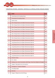
WELLHEADS, X-MAS TREES, GATE VALVES, MANIFOLDS INDEX<br />
SR.<br />
NO.<br />
INDEX<br />
PAGE<br />
1 Casing Head 2<br />
2 Casing Head Spool 3<br />
3 Casing & Tubing Hanger 4<br />
4 Tubing Hanger Spool & Coupling 8<br />
5 Bottom Pack-of f Cross Over Seal 9<br />
6 Tubing Head 10<br />
7 Tubing Head Spool 11<br />
8 Tools & Service Equipment 12<br />
9 Choke Valve 15<br />
10 Gate Valve 18<br />
11 Typical Single & Dual Completion Wellhead & X-mas Tree Assemblies 23<br />
12 Choke And Kill Manifold 24<br />
13 X-mas Tree Cap 25<br />
14 Single Completion Component 26<br />
1
<strong>Wellheads</strong>, X-mas Trees, Gate Valves, Manifolds<br />
CASING HEAD<br />
PARVEEN’s 'PCH' Casing Head e.g. Casing Head<br />
Housing (PCHH) and Casing Head Spool (PCHS)<br />
accept Automatic Casing Hanger (PCHA), Unitised<br />
Casing Hanger (PCHU), S-Slips (PS) & S-Pack of f<br />
(PSPO) assembly and can be furnished with female<br />
thread or slip-on weld lower connection. Standard<br />
outlets are 2” LINE PIPE threads or 2” API extended<br />
flanged with optional VR THREADS and end<br />
connection may be threaded or slip on weld type. Hold<br />
down screws to energize the annulus seal can be<br />
furnished on request.<br />
h<br />
B<br />
A<br />
H<br />
Parveen Casing Head Housing (PCHH) Threaded Type<br />
(Caution: Casing Hangers with attached seals which<br />
are not held down by hold down screws may be<br />
unseated when the annulus pressure multiplied by the<br />
annulus area exceeds the pipe load).<br />
NOTES:<br />
1) All dimension are in inches.<br />
PARVEEN CASING HEAD HOUSING (PCHH) DIMENSIONS<br />
2) Landing Bases are available with housings.<br />
Slip-On Weld Conn<br />
Rating Top Casing Total Height Of Thru Bore Top<br />
Flange Size Height (H) Side Outlets Bore Flange<br />
Size (h) (Min A) (B)<br />
11 8 5/8 19 61/2 8 1/6 10 31/32<br />
11 9 5/8 19 6 1/2 9 1/8 10 31/32<br />
11 10 3/4 19 61/2 9 15/16 10 31/32<br />
2000 PSI 13 5/8 11 3/4 19 6 1/2 9 15/16 10 31/32<br />
* 13 5/8 13 3/8 19 6 1/2 12 1/2 13 19/32<br />
16 3/4 16 18 1/8 6 1/2 15 3/8 16 11/16<br />
21 1/4 20 15 11/16 5 18 15/16 20 1/4<br />
11 8 5/8 19 6 1/2 8 1/16 10 31/32<br />
11 9 5/8 19 6 1/2 9 1/8 10 31/32<br />
11 10 3/4 19 6 1/2 9 15/16 10 31/32<br />
3000 PSI 13 5/8 11 3/4 19 6 1/2 11 3/8 13 19/32<br />
* 13 5/8 13 3/8 19 6 1/2 12 1/2 13 19/32<br />
16 3/4 16 18 6 1/2 15 3/8 16 11/16<br />
20 3/4 20 15 11/16 6 1/2 18 15/16 20 1/4<br />
11 8 5/8 19 6 1/2 8 1/16 10 31/32<br />
5000 PSI 11 9 5/8 19 6 1/2 9 1/8 10 31/32<br />
* 11 10 3/4 19 6 1/2 9 15/16 10 31/32<br />
13 5/8 13 3/8 19 6 1/2 12 1/2 13 19/32<br />
3) * Casing thread connection limits maximum working pressure rating (as per API-6A) to 5000 psi for 4 1/2” - 10 3/4”<br />
casing, to 3000 psi for 11 3/4” - 13 3/8” casing & to 2000 psi for 16” - 20” casing.<br />
2
<strong>Wellheads</strong>, X-mas Trees, Gate Valves, Manifolds<br />
CASING HEAD SPOOL<br />
H<br />
h<br />
B<br />
A<br />
Parveen Casing Head Spool (PCHS)<br />
PARVEEN’s Casing Head Spool (PCHS) accepts<br />
automatic (PCHA) and unitised (PCHU) casing<br />
hangers. Standard outlets are 2 1/16”, 2000-10000 PSI<br />
WP. Studded or flanged outlets can also be furnished<br />
with threaded 2" Line pipe connection. Studded or<br />
flanged outlets have internal threads for valve removal<br />
<strong>plug</strong>s. Bottom of the flange is designed for installation<br />
on the bit guides and PARVEEN type PBP -1 & PBP - 2<br />
bottom pack-of f, CROSSOVER SEAL (PP Seal over<br />
5000 PSI WP) and is provided with a plastic packing<br />
injection port with bleeder outlet and a test port. For<br />
high pressure (over 3000 PSI W.P) the type 'PSPO'<br />
pack-of f is used at the top of the casing hanger to<br />
prevent collapse of the casing pipe. Hold down screws<br />
can be furnished on request.<br />
PARVEEN CASING HEAD SPOOL (PCHS) DIMENSIONS<br />
Flange Sizes<br />
Dimensions<br />
Bottom Top Overall Height Of Minimum Top Flange<br />
Height(H) Side Outlets (h) Bore ( A) Bore ( B)<br />
11 X 2000 11 X 2000 20 1/8 10 1/16 8 10 31/32<br />
11 X 2000 11 X 3000 20 5/8 10 1/16 8 10 31/32<br />
11 X 3000 11 X 3000 21 10 1/2 8 10 31/32<br />
11 X 3000 11 X 5000 23 3/4 10 5/8 8 10 31/32<br />
11 X 5000 11 X 5000 25 1/2 12 3/8 8 10 31/32<br />
13 5/8 X 2000 11 X 2000 20 1/4 10 3/16 9 15/16 10 31/32<br />
13 5/8 X 2000 11 X 3000 20 3/4 10 3/16 9 15/16 10 31/32<br />
13 5/8 X 3000 11 X 3000 21 1/2 11 9 15/16 10 31/32<br />
13 5/8 X 3000 11 X 5000 25 1/8 12 9 15/16 10 31/32<br />
13 5/8 X 5000 11 X 10000 25 1/2 12 3/8 9 15/16 10 31/32<br />
16 3/4 X 2000 11 X 2000 21 1/8 11 1/16 9 15/16 10 31/32<br />
16 3/4 X 2000 11 X 3000 22 3/4 10 3/4 9 15/16 10 31/32<br />
16 3/4 X 3000 11 X 3000 24 5/16 12 5/16 9 15/16 10 31/32<br />
16 3/4 X 3000 11 X 5000 26 12 3/8 9 15/16 10 31/32<br />
16 3/4 X 2000 13 5/8 X 2000 21 1/4 11 1/16 12 1/2 13 19/32<br />
16 3/4 X 3000 13 5/8 X 3000 22 7/8 11 15/16 12 1/2 13 19/32<br />
16 3/4 X 3000 13 5/8 X 5000 27 1/16 11 15/16 12 1/2 13 19/32<br />
21 1/4 X 2000 13 5/8 X 2000 22 1/16 11 7/8 12 1/2 13 19/32<br />
21 1/4 X 2000 13 5/8 X 3000 23 3/4 11 3/8 12 1/2 13 19/32<br />
NOTE :<br />
All Dimensions are in Inches.<br />
3
<strong>Wellheads</strong>, X-mas Trees, Gate Valves, Manifolds<br />
CASING & TUBING HANGER<br />
Automatic Casing, Hanger (PCHA) is basically<br />
designed for heavy load service and is used for<br />
PARVEEN's Casing Head Housing 'PCHH' and Casing<br />
Head Spool 'PCHS' described earlier. When the Casing<br />
load is applied to the hanger, the top ring connected by<br />
the Pack-of f and shoulder screw compresses the<br />
packing to seal the annulus pressure of the casing. This<br />
casing hanger is normally used for pressure ratings upto<br />
3000 PSI. For ratings over 3000 PSI, type 'PSPO' Pack-of f<br />
is used to prevent collapse of the pipe.<br />
Unitised Casing Hanger (PCHU) can be used both for<br />
PARVEEN's Casing Head Housing (PCHH) and Casing<br />
Head Spool (PCHS) as described earlier. This Hanger is<br />
designed for medium or heavy load service. This hanger<br />
is normally latched around the pipe and lowered in<br />
casing head body. After the casing is landed, shoulder<br />
screws should be evenly tightened to af fect a positive<br />
annular seal. The hanger may be used upto 3000 PSI WP.<br />
For ratings over 3000 PSI, 'PSPO' Pack-off is used to<br />
prevent collapse of the pipe.<br />
S PACK-OFF<br />
PCHA<br />
Type PCHA Automatic Casing<br />
Hanger with Slip Seal Assly<br />
Casing Hanger - PARVEEN<br />
Casing Hangers are<br />
basically 2 types, i.e.<br />
Automatic Casing Hanger<br />
(PCHA) and Unitised<br />
Casing Hanger (PCHU).<br />
S-Slips (PS) and S-Pack of f<br />
(PSPO) assembly are also<br />
shown.<br />
S PACK-OFF<br />
PCHU<br />
Type `PCHU' Unitised Casing<br />
Hanger with Slip Seal Assly<br />
S PACK-OFF<br />
(PSPO)<br />
S-SLIP<br />
(PS)<br />
Type S-Slip (PS) Casing Hanger<br />
with S-Pack-off (PSPO) and S-Slip<br />
Nominal<br />
SPECIFICATIONS OF PARVEEN’S CASING HANGER<br />
Flange Size 4 1/2 5 5 1/2 6 5/8 7 7 5/8 8 5/8 9 5/8 10 3/4 11 3/4 13 3/8 16<br />
9 PCHA PCHA<br />
PCHU PCHU PCHU<br />
Casing Size<br />
11 PCHA PCHA PCHA PCHA PCHA PCHA PCHA<br />
PCHU PCHU PCHA PCHU PCHU PCHU<br />
13 5/8 PCHA PCHA PCHA PCHA PCHA<br />
PCHU PCHU PCHU PCHU<br />
16 3/4 PCHA PCHA<br />
PCHU PCHU PCHU<br />
20 3/4 & PCHA<br />
21 1/4 PCHU<br />
Nominal<br />
Flange Size 4 1/2 5 5 1/2 6 5/8 7 7 5/8 8 5/8 9 5/8 10 3/4 11 3/4 13 3/8 16<br />
9 PS PS PS<br />
Casing Size<br />
11 PS PS PS PS PS PS PS<br />
PSPO PSPO PSPO PSPO PSPO PSPO<br />
13 5/8 PS PS PS PS PS PS PS<br />
PSPO PSPO PSPO PSPO PSPO PSPO<br />
16 3/4 PS PS PS<br />
PSPO PSPO PSPO<br />
20 3/4 & PS PS PS<br />
21 1/4 PSPO PSPO PSPO<br />
PCHA: PARVEEN’s Automatic Casing Hanger, PS: PARVEENS’s S - Slip,<br />
PCHU: PARVEEN’s Unitised Casing Hanger, PSPO: PARVEEN’s S - Pack-of f.<br />
4
<strong>Wellheads</strong>, X-mas Trees, Gate Valves, Manifolds<br />
CASING & TUBING HANGER<br />
Tubing Hangers - PARVEEN's Tubing Hangers are basically<br />
four types. These are Mandrel Type 'PTHSM', Wrap Around<br />
Type 'PTHSW', Extended Neck Type 'PTHSE' and Dual Split<br />
Type 'PTHDE'. Extended Neck Type with control lines<br />
'PTHSCL', Dual Split Type with control lines 'PTHDCL',<br />
mandrel type with metal to metal seals (PTHTSM) and<br />
Mandrel type equipped with a continuous control line with<br />
metal to metal seals such as PTHTSMM are also supplied.<br />
Type PTHSE<br />
Extended Neck Hanger<br />
'PTHSM' type Tubing Hanger is used for the PTHS type of<br />
Tubing Head Spool described later. It seals the annulus<br />
pressure by compressing the seal with the weight of the<br />
tubing and the hold down screws.<br />
Extended Neck Type 'PTHSE' is used for the Tubing<br />
Head/Spool described later. This type is like 'PTHSM' type<br />
tubing hanger but having an extended neck with a seal ring<br />
which seals fluid in the tubing. This type seals the annulus<br />
pressure by compressing the seal with the weight of the<br />
tubing and the hold down screws.<br />
Type PTHSW<br />
Wrap Around Hanger<br />
The 'PTHSW' type is a split type tubing hanger and may be<br />
wrapped round the tubing. It seals the annulus pressure by<br />
compressing the seal with the hold down screws installed in<br />
the top flanges of the spool. This type of hanger is used<br />
where tubing must be rotated or moved up and down under<br />
pressure. This tubing hanger is used together with a tubing<br />
hanger coupling and a tubing hanger spool.<br />
Specifications of PTHSM & PTHSE Type Hangers<br />
Nominal Tubing<br />
Lift & Suspension Threads<br />
Flange Hanger<br />
Size<br />
Type 2 3/8 Up TBG 2 7/8 Up TBG 3 1/2 Up TBG 4 1/2 Up TBG<br />
PTHSM X X X X<br />
7 1/16 PTHSE X X X X<br />
PTHSM X X X X<br />
9 PTHSE X X X X<br />
PTHSM X X X X<br />
11 PTHSE X X X X<br />
NOTE:<br />
1) X-API standard tubing threads.<br />
2) These hangers can also be of fered with premium threads at request.<br />
3) All sizes are in inches.<br />
5
<strong>Wellheads</strong>, X-mas Trees, Gate Valves, Manifolds<br />
CASING & TUBING HANGER<br />
Dual split type Tubing Hanger 'PTHDE' is used for<br />
Dual Tubing String applications. This utilises plastic<br />
packing between the seals for sealing. It is fixed by hold<br />
down screws.<br />
Dual split type tubing hangers can also be fitted with<br />
hydraulic control lines 1 or 2 called 'PTHDCL1' &<br />
'PTHDCL2'.<br />
PTHDE Tunbing Hanger<br />
Specifications of ‘PTHDE’ Type Tubing Hangers<br />
Tubing Bore Centre to Nominal Casing Pipe<br />
Pipe Bore Centre Flange Size O.D. Weight<br />
1.90 x 1.90 2 25/32 7 1/16 5 1/2 17 LBS/FT<br />
2 3/8 x 2 3/8 3 25/32 7 1/16 7 38 LBS/FT<br />
2 7/8 x 2 3/8 3 35/64 7 1/16 7 29 LBS/FT<br />
2 7/8 x 2 3/8 4 9 7 5/8 39 LBS/FT<br />
2 7/8 x 2 7/8 4 9 7 5/8 29.7 LBS/FT<br />
2 7/8 x 2 7/8 4 1/2 9 8 5/8 49 LBS/FT<br />
3 1/2 x 2 7/8 5 3/64 11 9 5/8 53.5 LBS/FT<br />
3 1/2 x 3 1/2 5 3/64 11 9 5/8 53.5 LBS/FT<br />
NOTE: All dimensions are in Inches.<br />
Extended Neck Type Tubing hangers are equipped<br />
with a control line (or lines) to control the opening and<br />
closing of sub-surface safety <strong>valves</strong> (SSSV) from the<br />
surface. These are called 'PTHSCL1' & 'PTHSCL2'.<br />
Type "PTHDCL1".<br />
Type "PTHDCL2".<br />
The type 'PTHSCL1' is equipped with 1 (1/4") hydraulic<br />
control line while 'PTHSCL2' is equipped with 2<br />
hydraulic control lines. Both these types seal the<br />
annulus pressure by compressing the seal with the<br />
hold down screws installed in the type 'PTHS' Tubing<br />
spool top flange.<br />
Extended Neck type Tubing Hangers<br />
Specifications for ‘PTHSCL & PTHDCL’ Tubing Hangers<br />
Nominal Tubing<br />
Lift & Suspension Threads<br />
Flange Hanger<br />
Size<br />
Type 2 3/8 Up TBG 2 7/8 Up TBG 3 1/2 Up TBG 4 1/2 Up TBG<br />
7 1/16<br />
PTHSCL X X X<br />
PTHDCL X X<br />
9<br />
PTHSCL X X X X<br />
PTHDCL X X X X<br />
11 PTHSCL X X X X<br />
PTHDCL X X X X<br />
NOTE:<br />
1) X-API Standard Tubing Threads.<br />
2) These hangers can also be of fered with premium threads at request.<br />
3) All sizes are in inches<br />
6
<strong>Wellheads</strong>, X-mas Trees, Gate Valves, Manifolds<br />
CASING & TUBING HANGER<br />
PARVEEN's Mandrel Type Tubing Hanger with metal to metal seals called 'PTHTSM' are used with PARVEEN's Tubing<br />
Spool and are equipped with metal to metal seal for fluids which prohibit the use of elastomer seals. These hangers<br />
have metal rings at the top and bottom for sealing. The rated working pressure range is 5000 psi to 15000 psi.<br />
PARVEEN's PTHTSMM hangers fitted with single or dual hydraulic control lines are called PTHTSMM1 & PTHTSMM2.<br />
These are equipped with metal to metal seals for fluids prohibiting the use of elastomeric seals. Sealing is af fected by<br />
metal ring mounted on the top of the hanger and load applied to the bottom of the hanger body.<br />
Tubing Head Adapters<br />
PARVEEN's Tubing Head Adaptors are designed for tubing suspension and can be used with extended neck threaded<br />
hanger PTHSE for a max WP of 15000 PSI. These can be provided with a studded up connections and a recessed lower<br />
flange with test & bleed ports. Tubing Head Adaptors can also be used with wrap around tubing hanger (PTHSW) for a<br />
max. WP of 10000 PSI and are threaded female for tubing suspension. It can be threaded according to the customer<br />
specification.<br />
Type PTHSE Tubing Head Adaptor<br />
Type PTHSW Tubing Head Adaptor<br />
Tubing Head Adapters PTHSE Specifications<br />
Bottom Studded Min.<br />
Flange Size Top Flange Bore<br />
Tubing Head Adapters PTHSW Specifications<br />
Bottom Studded Thread Size Min.<br />
Flange Size Top Flange API-Up TBG Bore.<br />
7 1/16 x 2000<br />
7 1/16 x 3000<br />
7 1/16 x 5000<br />
7 1/16 x 10000<br />
7 1/16 x 15000<br />
2 1/16 x 2000 2 1/16<br />
2 1/16 x 5000 2 1/16<br />
2 9/16 x 2000 2 9/16<br />
2 9/16 x 5000 2 9/16<br />
3 1/8 x 2000 3 1/8<br />
3 1/8 x 3000 3 1/8<br />
2 1/16 x 5000 2 1/16<br />
2 9/16 x 5000 2 9/16<br />
3 1/8 x 3000 3 1/8<br />
3 1/8 x 5000 3 1/8<br />
2 1/16 x 5000 2 1/16<br />
2 9/16 x 5000 2 9/16<br />
3 1/8 x 5000 3 1/8<br />
2 9/16 x 10000 2 9/16<br />
3 1/16 x 10000 3 1/16<br />
2 1/16 x 15000 2 1/16<br />
2 9/16 x 15000 2 9/16<br />
2 1/16 x 2000 2 3/8 2 1/16<br />
2 1/16 x 5000 2 3/8 2 1/16<br />
7 1/16 x 2000 2 9/16 x 2000 2 7/8 2 9/16<br />
2 9/16 x 5000 2 7/8 2 9/16<br />
3 1/8 x 2000 3 1/2 3 1/8<br />
3 1/8 x 3000 3 1/2 3 1/8<br />
2 1/16 x 5000 2 3/8 2 1/16<br />
7 1/16 x 3000 2 9/16 x 5000 2 7/8 2 9/16<br />
3 1/8 x 3000 3 1/2 3 1/8<br />
3 1/8 x 5000 3 1/2 3 1/8<br />
2 1/16 x 5000 2 3/8 2 1/16<br />
7 1/16 x 5000 2 9/16 x 5000 2 7/8 2 9/16<br />
3 1/8 x 5000 3 1/2 3 1/8<br />
7 1/16 x 10000 2 9/16 x 10000 2 7/8 2 9/16<br />
NOTE:<br />
1) Other sizes available on request.<br />
2) All Dimensions are in inches.<br />
7
<strong>Wellheads</strong>, X-mas Trees, Gate Valves, Manifolds<br />
TUBING HANGER SPOOL & COUPLING<br />
PARVEEN also manufactures Tubing Hanger Spools and Tubing<br />
Hanger Couplings. Tubing Hanger Spool is used in combination<br />
with Tubing Hanger coupling, Wrap around tubing hanger (PTHSW)<br />
and 'PTHS' type tubing spool. Tubing Hanger Coupling allows<br />
installation by screwing the union nut of the tubing hanger coupling<br />
without a need to turn the X-mas tree. Coupling is threaded for<br />
installing a back pressure valve. Top & Bottom of the coupling can be<br />
threaded to suit customer's requirement.<br />
SPECIFICATIONS OF TUBING HANGER COUPLING<br />
Size<br />
4 1/2 x 2 3/8 API UPSET TUBING<br />
4 1/2 x 2 7/8 API UPSET TUBING<br />
6 5/16 x 3 1/2 API UPSET TUBING<br />
6 7/8 x 4 1/2 API UPSET TUBING<br />
Tubing Hanger Coupling<br />
SPECIFICATIONS OF TUBING HANGER SPOOL<br />
Bottom Flange x Studded Bore Bottom<br />
Top Flange<br />
Prep<br />
7 1/16 2000 x 2 9/16 2000 2 9/16 4 ½<br />
7 1/16 3000 x 2 1/16 5000 2 1/16 4 1/2<br />
7 1/16 3000 x 2 9/16 5000 2 9/16 4 1/2<br />
7 1/16 5000 x 2 1/16 5000 2 1/16 4 1/2<br />
7 1/16 5000 x 2 9/16 5000 2 9/16 4 1/2<br />
7 1/16 5000 x 3 1/8 5000 3 1/8 6 5/16<br />
7 1/16 5000 x 4 1/16 5000 4 1/8 6 7/8<br />
9 5000 x 2 1/16 5000 2 1/16 4 1/2<br />
9 5000 x 3 1/8 5000 3 1/8 6 5/16<br />
9 5000 x 4 1/16 5000 4 1/8 6 7/8<br />
11 5000 x 2 9/16 5000 2 9/16 4 1/2<br />
7 1/16 10000 x 2 1/16 10000 2 1/16 4 1/2<br />
7 1/16 10000 x 2 9/16 10000 2 9/16 4 1/2<br />
7 1/16 10000 x 3 1/16 10000 3 1/16 6 5/16<br />
9 10000 x 4 1/16 10000 4 1/16 6 7/8<br />
7 1/16 15000 x 1 13/16 15000 1 13/16 4 1/2<br />
7 1/16 15000 x 2 1/16 15000 2 1/16 4 1/2<br />
7 1/16 15000 x 2 9/16 15000 2 9/16 4 1/2<br />
Tubing Hanger Spool<br />
NOTE :<br />
All dimensions are in inches<br />
8
<strong>Wellheads</strong>, X-mas Trees, Gate Valves, Manifolds<br />
BOTTOM PACK-OFF CROSS OVER SEAL<br />
The standard bottom pack - off is type 'PBP1’<br />
The bottom pack - of f is installed in the lower flange of<br />
the casing head spool and tubing head spool to<br />
prevent the lower flange from being exposed to high<br />
pressure.<br />
The bottom pack-of f type 'PBP1' seals the annulus<br />
pressure by injecting packing. The bottom pack - of f<br />
PBP - 2 is designed to give a positive annular seal with<br />
pressure energized oversize O - Rings.<br />
For services at working pressures above 5,000 psi,<br />
the 'PP' seal is used.<br />
When the bottom pack - of f is used, the casing should<br />
be cut 90 mm from the top flange surface of the<br />
connecting spool.<br />
Bottom Pack-OFF (PBP-1)<br />
Nominal<br />
Casing Pipe<br />
Flange Size 4 1/2 5 5 1/2 6 5/8 7 7 5/8 8 5/8 9 5/8 10 3/4 11 3/4 13 3/8<br />
9 O O O<br />
11 O O O O O *<br />
13 5/8 O O O O O O<br />
16 3/4 O O O<br />
20 3/4 &21 1/4 O O O<br />
O Type ‘PBP-1’, * Type ‘PBP-2’<br />
NOTE:<br />
All sizes are in inches<br />
9
<strong>Wellheads</strong>, X-mas Trees, Gate Valves, Manifolds<br />
TUBING HEAD<br />
PARVEEN's Tubing Head Spools (PTHS) body<br />
have a straight bore with a 45 deg landing shoulder.<br />
While the top flange has hold down screws as<br />
standard equipment for securing tubing hanger,<br />
the bottom flange is designed for installation of<br />
PARVEEN's bottom pack - of f PBP-1 & PBP - 2 (PPseal<br />
for high pressure over 5000 PSI) and is<br />
provided with bit guide, a plastic packing injection<br />
port with bleeder outlet and a test port. This can<br />
accept Tubing Hangers Mandrel Type 'PTHSM',<br />
Wrap around type 'PTHSW' and Extended neck<br />
type 'PTHSE'.<br />
B<br />
A<br />
h<br />
H<br />
Standard outlets are 2 1/16” 2000 -10000 PSI WP<br />
studded. Even 2” Line Pipe & Flanged outlets can<br />
also be provided. Studded outlets are threaded<br />
internally for the valve removal <strong>plug</strong>s. Top flange is<br />
provided with hold down screws to secure tubing<br />
hanger.<br />
Parveen’s Tubing Head Spool (PTHS)<br />
Parveen's Tubing Head Spool (PTHS) Dimension.<br />
Flange Sizes<br />
Overall Height Of Minimum Top Flange<br />
Bottom<br />
Top Height(H) Side Outlets (h) Bore ( A) Bore ( <br />
B)<br />
9 X 2000 7 1/16 X 2000 16 7 15/16 6 1/2 7 1/32<br />
9 X 2000 7 1/16 X 3000 16 7 15/16 6 1/2 7 1/32<br />
9 X 2000 7 1/16 X 3000 16 7 15/16 6 13/16 7 1/32<br />
9 X 3000 7 1/16 X 5000 16 8 1/16 6 13/16 7 1/32<br />
11 X 2000 7 1/16 X 2000 16 8 1/16 6 13/16 7 1/32<br />
11 X 2000 7 1/16 X 3000 16 8 1/16 6 13/16 7 1/32<br />
11 X 3000 7 1/16 X 3000 19 1/2 10 1/2 6 13/16 7 1/32<br />
11 X 3000 7 1/16 X 5000 22 7/8 12 3/8 6 13/16 7 1/32<br />
11 X 5000 7 1/16 X 5000 23 1/2 10 3/4 6 13/16 7 1/32<br />
11 X 2000 9 X 2000 16 8 1/16 8 1/16 8 3/4<br />
11 X 2000 9 X 3000 16 8 1/16 8 1/16 8 3/4<br />
11 X 3000 9 X 3000 19 1/2 10 1/2 8 1/16 8 3/4<br />
11 X 3000 9 X 5000 22 7/8 12 3/8 8 1/16 8 3/4<br />
11 X 5000 9 X 5000 25 12 3/4 8 1/16 8 3/4<br />
11 X 5000 7 1/16 X 10000 25 12 3/4 6 9/16 7 1/32<br />
11 X 5000 9 X 10000 25 12 3/4 8 1/16 8 3/4<br />
11 X 10000 7 1/16 X 10000 26 3/8 12 3/4 6 3/8 7 1/32<br />
11 X 10000 7 1/16 X 15000 27 3/8 12 3/4 6 3/8 7 1/32<br />
NOTE:<br />
All Dimensions are in Inches.<br />
10
<strong>Wellheads</strong>, X-mas Trees, Gate Valves, Manifolds<br />
TUBING HEAD SPOOL<br />
B<br />
PTHD Tubing Head Spools are designed for the<br />
popular split hanger suspensions for dual<br />
completions. It has welded wedges for hanger<br />
alignment and an open - face top flange.<br />
A<br />
Parveen’s Tubing Head Spool (PTHD)<br />
h<br />
H<br />
Type 'PTHD' Tubing Spool accepts either the<br />
'PTHDE', 'PTHSCL', 'PTHDCL' tubing hangers. This<br />
tubing spool is provided with a wedge to position the<br />
hanger. The standard outlets are 2 1/16 2000-10000<br />
PSI WP studded. The outlets are threaded for the<br />
valve removal <strong>plug</strong> to allow for the removal of the<br />
valve. The bottom of the flange is designed for<br />
installing the type PBP-1 Bottom pack of f (PP Seal<br />
for high pressure over 5000 PSI WP) and is provided<br />
with a plastic packing injection port and a test port.<br />
The top of the spool is provided with hold down<br />
screws to secure the tubing hanger.<br />
Parveen's Tubing Head Spool (PTHD) Dimensions :-<br />
Flange Sizes<br />
Overall Height Of Minimum Top Flange<br />
Bottom<br />
Top<br />
Height(H) Side Outlets (h) Bore ( A) Bore ( B)<br />
11 X 2000 7 1/16 X 2000 20 1/2 10 6 3/8 6 61/64<br />
11 X 3000 7 1/16 X 3000 20 1/2 10 6 3/8 6 61/64<br />
11 X 3000 7 1/16 X 5000 22 11 1/2 6 3/8 6 61/64<br />
11 X 5000 7 1/16 X 5000 23 3/4 11 11/16 6 3/8 6 61/64<br />
11 X 5000 7 1/16 X 10000 25 12 3/4 6 3/8 6 61/64<br />
11 X 3000 9 X 3000 22 1/4 11 5/8 6 13/16 8 59/64<br />
11 X 3000 9 X 5000 23 3/8 12 3/4 6 13/16 8 59/64<br />
11 X 5000 9 X 5000 25 12 3/4 6 13/16 8 59/64<br />
11 X 5000 9 X 10000 27 3/8 14 3/8 6 13/16 8 59/64<br />
13 5/8 X 3000 9 X 3000 22 3/4 11 5/8 8 1/16 8 59/64<br />
13 5/8 X 3000 9 X 5000 23 7/8 12 3/4 8 1/16 8 59/64<br />
13 5/8 X 5000 9 X 5000 24 7/8 12 3/4 8 1/16 8 59/64<br />
13 5/8 X 3000 7 1/16 X 3000 22 1/2 10 6 3/8 6 61/64<br />
13 5/8 X 3000 7 1/16 X 5000 23 5/8 11 1/8 6 3/8 6 61/64<br />
11 X 10000 7 1/16 X 10000 28 1/2 12 3/4 6 3/8 6 61/64<br />
11 X 10000 7 1/16 X 15000 29 1/8 13 3/8 6 3/8 6 61/64<br />
11 X 10000 9 X 10000 30 3/4 15 6 13/16 8 59/64<br />
NOTE:<br />
All Dimensions are in Inches.<br />
11
<strong>Wellheads</strong>, X-mas Trees, Gate Valves, Manifolds<br />
TOOLS & SERVICE EQUIPMENT<br />
Casing Head Body Retrievable Wear Bushing (PRWB)<br />
These retrievable wear bushings (PRWB) protect the inner<br />
containers of casing head bodies or spools during drilling<br />
operations.<br />
When wear bushings are used, either hold down screws in the<br />
top flange of the casing head body or hold down flanges with<br />
hold down screws are required.<br />
Retrieving Tool (PRT)<br />
This tool (PRT) is meant for retrieving the wear bushing<br />
described above. It is inserted in the slot provided in the wear<br />
bushing top surface, rotated and then pulled up with the<br />
tools.<br />
Casing Head Body Retrievable<br />
Wear Bushing (PRWB)<br />
BOP Test Plug (PTP)<br />
These <strong>plug</strong> Testers fit all nominal sizes of casing head bodies<br />
and tubing heads and are available with any standard tool<br />
joint.<br />
The test <strong>plug</strong>s are assembled in the drill string and lowered to<br />
its seat in the casing head body or tubing head. Pipe rams of<br />
the preventors are then closed and hydraulic test pressure is<br />
applied below the rams.<br />
Blind rams can be tested in the same manner after removing<br />
the drill string.<br />
Back Pressure Valve (PBPV).<br />
Tubing hanger bushing are furnished with female lift and<br />
suspension threads and are machined to accommodate the<br />
type (PBPV) back pressure valve as shown in the figure.<br />
With Blowout Preventor equipment attached to the tubing<br />
head body, the tubing is run to the desired depth and the<br />
bushing, with the type (PBPV) back pressure valve installed,<br />
is made-up on the landing joint.<br />
The wrap around hanger is then latched around the tubing<br />
below the hanger bushing and lowered thru the BOP to its<br />
position in the tubing head body by means of a landing joint.<br />
After making sure that the hanger have fully landed in the<br />
head, hold down screws are fully tightened to compress the<br />
packing and secure it in place. Thereafter the landing joint &<br />
BOP may be removed.<br />
Attach the landing joint and raise the tubing enough to install<br />
a spider and slips. With tubing weight on the slips, remove<br />
landing joint.<br />
Casing Head Plug<br />
Type Tester (PTP)<br />
Type (PBPV) Back<br />
Pressure Valve<br />
Type (PBPV) Back<br />
Pressure Valve<br />
12
<strong>Wellheads</strong>, X-mas Trees, Gate Valves, Manifolds<br />
TOOLS & SERVICE EQUIPMENT<br />
The Hanger Spool with X-Mas Tree Manifold attached is<br />
then lowered and sealed on the hanger bushing. The union<br />
nut may now be made up by hand and a spanner wrench.<br />
The tree cannot now be rotated.<br />
Raise the tree assembly enough to remove the spider and<br />
slips. At this point, the well can be displaced and the packer<br />
set under complete pressure control.<br />
Final nipple up operations are then completed and the type<br />
PBPV back pressure valve is removed from the hanger<br />
bushing with a lubricator.<br />
Flanged Drilling Spool (PFDS)<br />
Flanged Drilling Spool (PFDS)<br />
These are designed to allow unrestricted circulation of mud<br />
in the well and provide flexibility in arranging flow line<br />
openings in blowout preventor hookups. Studded or open<br />
faced ends and outlet connections can be provided.<br />
Generally hub of the flanged outlet is welded. Height of<br />
spool will vary form 24" -36". However spools as per specific<br />
need of customers can also be provided.<br />
Type (PVRP) Plug<br />
Valve Removal Plugs (PVRP)<br />
All flanged or studded outlets on PARVEEN's casing heads,<br />
casing spools and tubing heads are threaded for valve<br />
removal <strong>plug</strong>s. All <strong>plug</strong>s have standard API Line Pipe<br />
Threads and are small enough to pass thru the valve to be<br />
removed. The <strong>plug</strong> is installed when the valve is to be<br />
removed and removed when the valve is to be installed.<br />
A<br />
B<br />
C<br />
Valve Removal Tool (PVRT)<br />
Valve Removal Tool (PVRT)<br />
These are generally pressure-balanced manual hydraulic<br />
tool designed for safe and reliable operations in the<br />
installation and removal of valve removal <strong>plug</strong>s, in order to<br />
install or replace a well-head outlet valve under pressure<br />
conditions.<br />
This tool is also designed to accommodate 2 1/16”, 2 9/16”,<br />
3 1/8” Valve upto 10000 PSI WP. Adapter may be provided for<br />
use with 1 13/16”, 2 1/16”, 2 9/16”, 3 1/8” flanged <strong>valves</strong> and<br />
screwed end <strong>valves</strong>. Various sizes of valve removal <strong>plug</strong><br />
sockets are also provided for the respective sizes of <strong>plug</strong>s.<br />
In the figure above, Needle Valve ‘A’ is located next to<br />
pressure gauge on manifold by-pass assembly and needle<br />
valve ‘B’ is connected to 1/2" NPT TEE on far end of manifold<br />
bypass assembly. Needle Valve 'C' is a bleeder valve<br />
located behind flange packing.<br />
13
<strong>Wellheads</strong>, X-mas Trees, Gate Valves, Manifolds<br />
TOOLS & SERVICE EQUIPMENT<br />
Lubricator (PL)<br />
PARVEEN's Lubricators which connect directly to the top<br />
of a X-Mas tree above the master valve are available in<br />
various sizes and end connections and pressure ratings<br />
varying from 5000 to 20000 PSI both for standard and sour<br />
service.<br />
Operating a Lubricator is by far the most dangerous<br />
aspect of well head service work. Therefore extreme<br />
caution has to be exercised while operating this tool.<br />
Measurement of Rod travel is done as follows:<br />
VALVE `A'.<br />
a. Measure from the tie down piece on the tubing head to<br />
the tree cap for a ball weevil hanger.<br />
Or<br />
b. Measure from the top of the tubing head adaptor<br />
bottom flange to the tree cap on a hanger bushing<br />
completion.<br />
In each case the window section of lubricator must also be<br />
measured. This will ensure that the proper length of the<br />
rod will be used. Most lubricator rods are marked in 5 such<br />
increments:<br />
VALVE `B'.<br />
a. Needle Valve A<br />
Valve located in manifold by pass assembly closest to<br />
adaptor flange.<br />
b. Needle Valve B<br />
Valve located on manifold bypass assembly closest to<br />
the first UNION connection.<br />
(NOTE: In lubricators upto 5000 PSI, needle valve B is<br />
also used as a bleed down valve. Needle valve C is<br />
used in 10000, 15000 & 20000 PSI lubricators to<br />
equalize pressure throughout the tool and not as<br />
bleed down <strong>valves</strong>.)<br />
c. Needle Valve C<br />
Only valve with a pressure gauge attached. Available<br />
in 10000, 15000 & 20000 PSI lubricators.<br />
Lubricator (PL)<br />
14
<strong>Wellheads</strong>, X-mas Trees, Gate Valves, Manifolds<br />
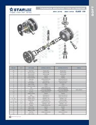
CHOKE VALVE<br />
5<br />
7<br />
11<br />
3<br />
1<br />
2<br />
4<br />
8<br />
9<br />
H2 TYPE CHOKE VALVE<br />
PARVEEN manufacture both Positive and Adjustable chokes in<br />
pressure rating up to 15,000 psi WP. With dif ferent style of end<br />
connection.<br />
Adjustable Chokes are meant for variable flow. It has externally<br />
th<br />
controlled indicator showing orifice size in the increment of 1/64<br />
inch .The variation in choke size is achieved by rotating hand<br />
wheel to obtain desired flow rate at down stream side<br />
10<br />
6<br />
12<br />
11<br />
13<br />
14<br />
16<br />
15<br />
17<br />
Adjustable Choke<br />
Part List<br />
ITEM DESCRIPTION QTY.<br />
1 HEX BOLT 1<br />
2 WASHER 1<br />
3 HANDLE 1<br />
4 HEX. SOC. SET SOCIETY 1<br />
5 INDICATOR 1<br />
6 BONNET NUT 1<br />
7 BONNET 1<br />
8 NYLON PLUG 1<br />
9 THUMB SCREW 1<br />
10 ‘O’ RING-BONNET 1<br />
11 JUNK RING 2<br />
12 ‘J’ PACKING + BACK-UP RING 1<br />
13 INT. RETAINER RING 1<br />
14 NEEDLE 1<br />
15 SEAT 1<br />
16 GASKET 1<br />
17 BODY 1<br />
PARVEEN Adjustable Chokes Contain following features:<br />
Interchangeability of parts to construct a positive, adjustable,<br />
or combination choke.<br />
Bonnet nut has rugged integrally forged lugs for hammering<br />
nut loose.<br />
Built-in safety feature which releases residual pressure in the<br />
choke body before the nut is fully removed. The inside of the<br />
choke body is vented to atmosphere after the bonnet nut is<br />
partially removed.<br />
Interchangeability of component parts for a particular<br />
pressure range. For example, the same blanking <strong>plug</strong>s and<br />
bonnet assemblies are used in nominal 2” 2000 through<br />
10,000 psi WP .<br />
Stainless steel adjustable choke needle and seat (Tungsten<br />
Carbide/ Ceramic lining needle and seat also available for<br />
severe service applications)<br />
Dif ferent end connections (API / ANSI, flanged / Threaded) are<br />
available upon request.<br />
Size &<br />
WP<br />
Max<br />
Orifice Dia<br />
2 1/16 x 2000 25.4 MM<br />
2 9/16 x 2000 50.8 MM<br />
3 1/8 x 2000 50.8 MM<br />
4 1/16 x 2000 76.2 MM<br />
2 1/16 x 3000 25.4 MM<br />
2 9/16 x 3000 50.8 MM<br />
3 1/8 x 3000 50.8 MM<br />
4 1/16 x 3000 76.2 MM<br />
2 1/16 x 5000 25.4 MM<br />
2 9/16 x 5000 50.8 MM<br />
3 1/8 x 5000 50.8 MM<br />
4 1/16 x 5000 76.2 MM<br />
2 1/16 x 10000 25.4 MM<br />
2 9/16 x 10000 50.8 MM<br />
3 1/16 x 10000 50.8 MM<br />
2 1/16 x 15000 25.4 MM<br />
3 1/16 x 15000 50.8 MM<br />
15
<strong>Wellheads</strong>, X-mas Trees, Gate Valves, Manifolds<br />
CHOKE VALVE<br />
Positive Chokes & Beans<br />
Positive Chokes accommodate fixed orifice dimensions. All<br />
PARVEEN Adjustable Chokes can be converted into Positive<br />
Chokes by replacing the bonnet assembly with an<br />
appropriate blanking <strong>plug</strong> assembly and choke bean .<br />
CHOKE BEANS :<br />
PARVEEN choke beans are suitably hardened to<br />
maintain accuracy level for longer period.<br />
Tungsten Carbide lined choke Beans are available for<br />
high pressure drop and severe application<br />
7<br />
9<br />
3<br />
2<br />
8<br />
5<br />
6<br />
4<br />
BEAN WRENCH:<br />
1<br />
PARVEEN Bean Wrench come with hexagonal socket box for<br />
Bean Adapter and Bean separately. The Adjustable choke<br />
seat and Bean Adapter are accommodated in same wrench<br />
for a particular size .<br />
Positive Choke<br />
Part List<br />
ITEM DESCRIPTION QTY.<br />
1 BODY 1<br />
2 BONNET 1<br />
3 BONNET NUT 1<br />
4 BEAN ADAPTER 1<br />
Choke Bean (BJ Type)<br />
5 CHOKE BEAN 1<br />
6 GASKET 1<br />
7 PLUG (½” NPT) 1<br />
8 ‘O’ RING-BONNET 1<br />
9 EXT. RETAINER RING 1<br />
Choke Bean (HJ Type)<br />
16
<strong>Wellheads</strong>, X-mas Trees, Gate Valves, Manifolds<br />
CHOKE VALVE<br />
1<br />
2<br />
3<br />
17<br />
27<br />
12<br />
14<br />
13<br />
15<br />
18<br />
19<br />
20<br />
21<br />
25<br />
4<br />
5<br />
9<br />
10<br />
6<br />
7<br />
8<br />
11<br />
16<br />
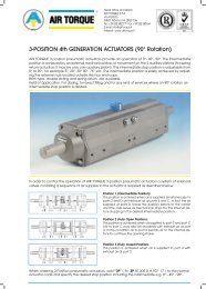
PARVEEN External sleeve control choke, (Model-ES)<br />
PARVEEN External sleeve control chokes minimize<br />
erosion and improve flow characteristics suitably for<br />
erosive service and under high pressure drop, with<br />
sand concentration. It applies the principle of “flow<br />
Impingement” to dissipate and contain the destructive<br />
forces of cavitation, within the heavy duty thick walled<br />
cage of tungsten carbide .<br />
Other features :<br />
Spring loaded pressure energized stem seal.<br />
Field proven metal bonnet seal .<br />
Dependable positive shut-of f .<br />
26<br />
23<br />
22<br />
24<br />
Part List<br />
External Sleeve Control Choke<br />
Size &<br />
WP<br />
Max<br />
Orifice Dia<br />
2.1/16 x 2000 25.4 mm<br />
2.9/16 x 2000 50.8 mm<br />
3.1/8 x 2000 50.8 mm<br />
4.1/16 x 2000 76.2 mm<br />
2.1/16 x 3000 25.4 mm<br />
2.9/16 x 3000 50.8 mm<br />
3.1/8 x 3000 50.8 mm<br />
4.1/16 x 3000 76.2 mm<br />
2.1/16 x 5000 25.4 mm<br />
2.9/16 x 5000 50.8 mm<br />
3.1/8 x 5000 50.8 mm<br />
4.1/16 x 5000 76.2 mm<br />
2.1/16 x 10000 25.4 mm<br />
2.9/16 x 10000 50.8 mm<br />
3.1/16 x 10000 50.8 mm<br />
2.1/16 x 15000 25.4 mm<br />
3.1/16 x 15000 50.8 mm<br />
ITEM DESCRIPTION QTY.<br />
1 HEX NUT 1<br />
2 WASHER 1<br />
3 HANDWHEEL 1<br />
4 HEX, SOC. SET SCREW 1<br />
5 INDICATOR 1<br />
6 STUD 8<br />
7 NUT 8<br />
8 BONNET 1<br />
9 NYLON BALL 1<br />
10 THUMB SCREW 1<br />
11 RING-BONNET 1<br />
12 JUNK RING 2<br />
13 SEAL 1<br />
14 BACK - UP RING - SEAL 1<br />
15 INT. RETAINER RING 1<br />
16 RETAINER RING - COIL TYPE 1<br />
17 STEM 1<br />
18 RING (2 HALVES) - STEM 1<br />
19 INT. RETAINER RING 1<br />
20 ‘O’ RING 1<br />
21 BACK-UP RING (SCARF CUT) 1<br />
22 SEAT 1<br />
23 SEAT SEAL 1<br />
24 BODY 1<br />
25 FLOW RING 1<br />
26 BODY VENT FITTING 1<br />
27 GREASE NIPPLE 1<br />
28 RIVET TAG (NOT SHOWN) 4<br />
29 NAME PLATE (NOT SHOWN) 1<br />
30 FLANGE PROTECTOR (NOT SHOWN) 2<br />
17
<strong>Wellheads</strong>, X-mas Trees, Gate Valves, Manifolds<br />
GATE VALVE<br />
MANUAL GATE VALVE<br />
PARVEEN manufacture Gate <strong>valves</strong> required for drilling and production operation in Slab<br />
and Expanding Gate style.<br />
G<br />
PARVEEN EXPANDING GATE VALVE MODEL ' M ' :<br />
EXPANDING STYLE GATE VALVES FOR 2000-5000 PSI. WP. APPLICATION<br />
Full bore through conduit<br />
Block and Bleed Mechanism<br />
Long-life seat<br />
Positive Seal by expand Mechanism<br />
In- line maintenance<br />
Non- Rising and Non- Balanced Stem<br />
Thrust bearing for the low torque operation<br />
J<br />
A<br />
Flanged Gate Valves<br />
(MODEL - M)<br />
F<br />
E<br />
FLANGED GATE VALVES OVERALL DIMENSIONS (As per API-6A Standard )<br />
Size Working Pressure A E F G J N Wt<br />
(PSI)<br />
2 1/16 2000 2 1/16 4 13/16 19 1/4 11 11 5/8 13 91<br />
3000/5000 5 1/16 19 7/16 13 14 5/8 150<br />
2 9/16 2000 2 9/16 5 5/8 20 3/16 13 13 1/8 15 1/2 125<br />
3000/5000 5 15/16 20 7/16 16 16 5/8 205<br />
(lbsf)<br />
3 1/8 2000 3 1/8 6 15/16 22 1/2 13 14 1/8 20 181<br />
3000 7 5/16 22 3/4 16 17 1/8 265<br />
5000 7 5/16 22 3/4 16 18 5/8 296<br />
G<br />
4 1/16 2000 4 1/16 8 5/8 25 15/16 16 17 1/8 24 1/2 345<br />
3000 91/16 26 3/8 20 20 1/8 515<br />
5000 9 1/16 26 3/8 20 21 5/8 530<br />
F<br />
PARVEEN FLANGED GATE VALVE MODEL ‘M’:<br />
The PARVEEN Flanged end <strong>gate</strong> <strong>valves</strong> are of the same standards as threaded end <strong>valves</strong>.<br />
Flanged end will conform to API-6A Spec . For Trims refer Trim Chart .<br />
THREADED GATE VALVES OVERALL DIMENSIONS<br />
Size Working Pressure A E F G J N Wt<br />
(PSI)<br />
(lbsf)<br />
A<br />
E<br />
Threaded Gate Valves<br />
(MODEL - M)<br />
J<br />
2 1/16 2000 2 1/16 4 13/16 19 1/4 11 9 5/8 13 71<br />
3000/5000 5 1/16 19 7/16 13 99<br />
2 9/16 2000 2 9/16 5 5/8 20 3/16 13 10 1/4 15 1/2 92<br />
3000/5000 5 15/16 20 7/16 16 125<br />
3 1/8 2000 3 1/8 6 15/16 22 1/2 13 11 3/8 20 152<br />
3000/5000 7 5/16 22 3/4 16 195<br />
4 1/16 2000 4 1/16 8 5/8 25 15/16 16 13 24 1/2 265<br />
3000/5000 91/16 26 3/8 20 379<br />
NOTE:<br />
0 0<br />
Standard Temperature Rating: -20 F to +250 F N = Numbers of Turns open.<br />
All Dimensions are in Inches.<br />
18
<strong>Wellheads</strong>, X-mas Trees, Gate Valves, Manifolds<br />
GATE VALVE<br />
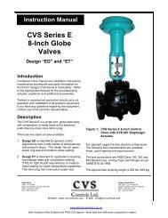
Parveen High Temperature Service : (Model T)<br />
Parveen High Temperature <strong>gate</strong> valve uses parallel expanding <strong>gate</strong> to obtain perfect shutof f. The sealing is metal - to<br />
metal, both on the up and down stream of the valve, and unaf fected by vibration and heat. The valve is the standard<br />
Model ‘E’ <strong>gate</strong> valve, modified with extended bonnet and stem to place the stem packing outside the critical heat zone.<br />
Other features and trim chart shall remain same for model E <strong>gate</strong> <strong>valves</strong>.<br />
Pressure Derating Table : (As recommended by API 6A)<br />
-20 to 250 F 300 F 650 F 400 F 450 F 500 F 550 F 600 F 650 F<br />
2000 1955 1905 1860 1810 1735 1635 1540 1430<br />
3000 2930 2860 2785 2715 2605 2455 2310 2145<br />
5000 4880 4765 4645 4525 4340 4090 3850 3575<br />
G<br />
E<br />
A<br />
F<br />
J<br />
DIMENSIONAL DATA FOR HIGH TEMPERATURE VALVE, UPTO 650 F<br />
Size Working A E F G J N WT IN<br />
Pressure<br />
LBS<br />
2.1/16” 2000 2.1/16 4.13/16 25.1/4” 11 11.5/8 13 96<br />
3000/5000 5.1/16 25.7/16 13 14.5/8 165<br />
2.9/16 2000 2.9/16 5.5/8 26.3/16 13 13.1/8 15.1/2 130<br />
3000/5000 5.15/16 26.7/16 16 16.5/8 220<br />
3.1/8 2000 3.1/8 6.15/16 28.1/2 13 14.1/8 20 186<br />
3000 7.5/16 28.3/4 16 17.1/8 273<br />
5000 7.5/16 28.3/4 16 18.5/8 311<br />
4.1/16 2000 4.1/8 8.5/8 31.15/16 16 17.1/8 24.1/2 351<br />
3000 9.1/16 32.3/8 20 20.1/8 523<br />
5000 9.1/16 32.3/8 20 21.5/8 545<br />
Flange specification conforms to API Standard 6A<br />
19
<strong>Wellheads</strong>, X-mas Trees, Gate Valves, Manifolds<br />
GATE VALVE<br />
18<br />
19<br />
15<br />
20<br />
17<br />
16<br />
9<br />
14<br />
12<br />
13<br />
8<br />
10<br />
11.a.<br />
11.b.<br />
11<br />
6<br />
7<br />
4.a.<br />
4.b.<br />
4.d.<br />
4<br />
4.c.<br />
Part List<br />
Flanged Gate Valve (Model - M)<br />
5<br />
2<br />
3<br />
1<br />
ITEM DESCRIPTION Qty.<br />
1 BODY 1<br />
2 BODY GREASE FITTING 2<br />
3 SEAT ASSY. 2<br />
3a SEAT 2<br />
3b TEFLON/T.F.E. RING 2<br />
4 GATE SEGMENT ASSY. 1<br />
4a GATE 1<br />
4b SEGMENT 1<br />
4c SPRING 2<br />
4d GATE PIN 6<br />
5 GATE GUIDE 2<br />
6 BONNET 1<br />
7 BONNET SEAL RING 1<br />
8 PACKING FITTING 1<br />
9 BONNET GREASE FITTING 1<br />
10 STUD WITH NUT 8<br />
11 PACKING SET 6<br />
11a HEADER PACKING RING 2<br />
11b ‘V’ PACKING RING 4<br />
12 PACKING RETAINER BUSHING 1<br />
13 BEARING SPACER SLEEVE 1<br />
14 THRUST BEARING 2<br />
15 STEM 1<br />
16 BEARING RETAINER NUT 1<br />
17 BEARING RETAINER LOCK NUT 1<br />
18 HAND WHEEL 1<br />
19 HAND WHEEL NUT 1<br />
20 WASHER FOR HANDWHEEL NUT 1<br />
20
<strong>Wellheads</strong>, X-mas Trees, Gate Valves, Manifolds<br />
GATE VALVE<br />
SLAB STYLE GATE VALVES FOR 2000-10,000 PSI W.P. APPLICATION<br />
Main features:<br />
Full bore through conduit<br />
Block and Bleed Mechanism<br />
Floating seat with self relief function<br />
In-line maintenance<br />
Metal to Metal sealing<br />
Metal to Metal stem back seat<br />
Heavy duty bearing for Low torque and easy operation<br />
Non-Rising and Non-Balanced Stem<br />
Forged Body and Bonnet Construction<br />
G<br />
A<br />
E F<br />
J<br />
Slab Flanged Gate Valve (Model - S)<br />
FLANGED GATE VALVE OVERALL DIMENSIONS. (As per API. 6A Standard )<br />
Size Working Pressure A E F G J N Wt<br />
(PSI)<br />
2 1/16 2000 2 1/16 5 5/8 21 1/8 14 11 5/8 12 1/2 110<br />
3000/5000 14 5/8 182<br />
2 9/16 2000 2 9/16 6 ½ 21 7/8 14 13 1/8 15 1/4 137<br />
3000/5000 16 5/8 255<br />
2000 14 14 1/8 193<br />
3 1/8 3000 3 1/8 7 3/8 22 13/16 14 17 1/8 18 1/4 282<br />
5000 18 1/2 18 5/8 360<br />
2000 16 17 1/8 395<br />
4 1/16 3000 4 1/16 9 1/8 24 7/16 18 1/2 20 1/8 23 1/2 450<br />
5000 21 5/8 545<br />
1 13/16 10,000 1 13/16 5 3/4 21 1/8 14 18 1/4 12 1/2 270<br />
2 1/16 10,000 2 1/16 5 7/8 21 1/8 18 1/2 20 ½ 12 1/2 275<br />
2 9/16 10,000 2 9/16 6 13/16 21 7/8 18 1/2 22 1/4 15 1/4 485<br />
3 1/16 10,000 3 1/16 8 1/16 21 13/16 24 24 3/8 18 1/4 680<br />
4 1/16 10,000 4 1/16 10 1/16 24 11/16 24 26 3/8 23 ½ 1050<br />
(lbsf)<br />
NOTE:<br />
0 0<br />
Standard Temperature Rating: - 20 F to + 250 F. N = Numbers of Turn open.<br />
G<br />
THREADED GATE VALVE OVERALL DIMENSIONS.<br />
F<br />
Size Working Pressure A E F G J N Wt<br />
(PSI)<br />
(lbsf)<br />
2 1/16 3000/5000 2 1/16 5 5/8 21 1/8 14 9 5/8 12 ½ 130<br />
2 9/16 3000/5000 2 9/16 6 ½ 21 7/8 14 10 1/4 15 1/4 190<br />
A<br />
E<br />
3 1/8 3000 3 1/8 7 3/8 22 13/16 14 11 3/8 18 1/4 210<br />
NOTE:<br />
0 0<br />
Standard Temperature Rating: - 20 F to + 250 F. N = Numbers of Turn open.<br />
All Dimensions are in Inches.<br />
J<br />
Slab Threaded Gate Valve<br />
(Model -S)<br />
21
<strong>Wellheads</strong>, X-mas Trees, Gate Valves, Manifolds<br />
GATE VALVE<br />
1<br />
8<br />
17<br />
3<br />
4<br />
2<br />
13<br />
12<br />
15<br />
18<br />
7<br />
9<br />
5<br />
6<br />
10<br />
11<br />
14<br />
16<br />
Part List<br />
24 19 23 20 21 26 25<br />
Slab Gate Valve (Model - S)<br />
ITEM DESCRIPTION Qty.<br />
1 HANDWHEEL ASSEMBLY 1<br />
2 BEARING CAP 1<br />
3 GREASE FITTING 2<br />
4 O-RING 1<br />
5 BEARING RACE 4<br />
6 THRUST BEARING 2<br />
7 O-RING 1<br />
8 STEM ADAPTER 1<br />
9 STEM PIN 1<br />
10 PACKING GLAND 1<br />
11 ‘J’ PACKING 1<br />
12 NUT 8<br />
13 STUD 8<br />
14 BONNET 1<br />
15 GREASE FITTING 1<br />
16 GASKET 1<br />
17 STEM 1<br />
18 GATE 1<br />
19 RETAINER PLATE 2<br />
20 SEAT RING 2<br />
21 SEAL RING (SEAT RING) 2<br />
22 PIN (Not shown) 2<br />
23 BODY 1<br />
24 GUIDE 2<br />
25 SEAL RING (BODY BUSHING) 2<br />
26 BODY BUSHING 2<br />
27 NAME PLATE (Not shown) 1<br />
22
<strong>Wellheads</strong>, X-mas Trees, Gate Valves, Manifolds<br />
TYPICAL SINGLE & DUAL COMPLETION WELLHEAD &<br />
X-MAS TREE ASSEMBLIES<br />
THREADED CONNECTIONS:<br />
All Integral equipment internal and outlet connection<br />
including Casing and Tubing Hanger which have API<br />
Threads, conform to API-5B stipulations for concerned<br />
tolerances.<br />
CHRISTMAS TREE:<br />
The equipment manufactured by PARVEEN include<br />
Tubing Head Adaptors, Valves, Trees, Crosses, Top<br />
Connectors and Chokes which can be assembled<br />
together and assembly can be used to provide<br />
controlled access to the Tubing String bore and control<br />
the rate of production.<br />
PARVEEN not only manufactures X-Mas Trees for<br />
single and multiple Tubing String installation but also<br />
the composite (block) X-Mas Trees for single and<br />
multiple Tubing String installations.<br />
Testing of X-Mas Trees is done as per Latest standard of<br />
API-6A which covers drift test and Hydrostatic test.<br />
Dual Completion<br />
Single Completion<br />
Single Completion<br />
23
<strong>Wellheads</strong>, X-mas Trees, Gate Valves, Manifolds<br />
CHOKE AND KILL MANIFOLD<br />
PARVEEN fabricates custom designed choke<br />
and kill manifold :<br />
1) In oil / gas well drilling operation, drilling fluids<br />
(Muds) of designed gravity are used to<br />
overcome sub-surface pressure or the influx of<br />
formation fluid. On some occasion, kicks are<br />
experienced with change of pressure of<br />
formation while drilling. This is necessary to<br />
build up drilling fluid density to prevent influx of<br />
formation fluid. The Choke and Kill Manifold<br />
allows the driller to regulate back-pressure on<br />
the formation while gradually density of the<br />
drilling fluid is built up by circulation with<br />
closed B.O.P., till the well is stabilized and<br />
drilling is resumed.<br />
Choke Manifold<br />
The Choke and Kill Manifold are available up to<br />
10,000 PSI in sizes of 2” to 3” for standard and<br />
sour services. Other type of Manifold (stand<br />
pipe, cementing etc.) can also be made<br />
available.<br />
2) For well Testing / Completion / Intervention,<br />
Industry uses varies configuration of Manifold,<br />
as per requirement of Service / Operating<br />
Companies, PARVEEN designs and fabricates<br />
custom made manifold in sizes of 2” to 3” up to<br />
10,000 PSI for standard and sour services for<br />
following application.<br />
Eruption Manifold<br />
(a) Choke Manifold For flow back/work over<br />
(b) Production Manifold for diverting flow<br />
through test separator or vent or burner.<br />
(c) Gas Manifold for Diverting gas through<br />
orifice meter or burner.<br />
(d) Data Recorder for recording flowing<br />
pressure and temperature.<br />
(e) Stimulation / Treatment for Well<br />
stimulation/treatment service.<br />
Choke & Kill Manifold<br />
24
<strong>Wellheads</strong>, X-mas Trees, Gate Valves, Manifolds<br />
X-MAS TREE CAP<br />
PARVEEN X-Mas Tree cap is a top connector which is used on the top of X-Mas Tree, It's main function is to provide<br />
access to the X-Mas Tree bore. It is basically consisting of a Flanged body, Blanking Plug, Hammer Nut as principal<br />
parts and Circlip & O-ring as secondary parts. Blanking Plug has a provision to accommodate pressure gauge to<br />
ascertain inside pressure of the well. Inside of Flanged body is having API-UP TBG thread as lift thread.<br />
Single Christmas Tree Cap<br />
SPECIFICATIONS<br />
Nominal Size Lift Thread Bore Height<br />
and WP.<br />
2 1/16-2000 2 3/8 API UP TBG 2 21/64 7 1/8<br />
2 9/16-2000 2 7/8 API UP TBG 2 53/64 7 1/16<br />
3 1/8-2000 3 1/2 API UP TBG 3 1/8 9 9/16<br />
3 1/8-3000 3 1/2 API UP TBG 3 1/8 9 13/16<br />
2 1/16-5000 2 3/8 API UP TBG 2 21/64 7 3/4<br />
2 9/16-5000 2 7/8 API UP TBG 2 53/64 8 1/16<br />
3 1/8-5000 3 1/2 API UP TBG 3 1/8 10 1/16<br />
4 1/16-5000 4 1/2 API UP TBG 4 13/64 12 1/8<br />
2 1/16-10000 2 3/8 API UP TBG 2 1/16 8<br />
2 9/16-10000 2 7/8 API UP TBG 2 9/16 7 9/16<br />
3 1/16-10000 3 1/2 API UP TBG 3 1/16 10 5/16<br />
4 1/16-10000 4 1/2 API UP TBG 4 1/16 13 1/8<br />
NOTE:<br />
All Dimensions are in inches.<br />
25
<strong>Wellheads</strong>, X-mas Trees, Gate Valves, Manifolds<br />
SINGLE COMPLETION COMPONENT<br />
PARVEEN also manufactures dif ferent types of Single Completion Components as per API-6A or Customer<br />
specification.<br />
Studded Cross<br />
Studded Tee<br />
Flanged Cross<br />
Flanged Tee<br />
Stud With Nuts<br />
Octagonal Ring Gasket<br />
Oval Ring Gasket<br />
Threaded Flange<br />
Double Studded Adaptor Flange<br />
Blind Flange<br />
Threaded<br />
Nipple<br />
Tapped<br />
Bull-Plug<br />
Solid<br />
Bull-Plug<br />
Solid<br />
Bull-Plug<br />
Spacer Spool<br />
NOTE:<br />
Multiple Completion Components (e.g. Dual Manifold Tee, Dual Adaptor Flange, Dual Completion Flanges, Multiple<br />
Completion Sub Seal etc.) can also be provided upon request.<br />
26
Flanges Studs & Nuts Ring Gaskets Pipe Fittings and Pipes, Valves<br />
PLUG VALVES<br />
A. Special Design Features<br />
1. PARVEEN valve bodies are made from alloy steel forgings which are designed to variety of end connections to be<br />
integrally machined.<br />
2. PARVEEN <strong>plug</strong> and inserts are designed to resist abrasion and corrosion.<br />
3. PARVEEN <strong>valves</strong> can be easily adopted for hydraulic or pneumatic actuation. These configurations are designed<br />
for integration with complete manifold systems.<br />
4. We manufacture in compliance with API-6A & API-Q1.<br />
5. Our range is up to 15000 PSI WP.<br />
B. Operating Principle<br />
1. The <strong>plug</strong> rotates 90° (1/4 turn) for rapid full open or close operation. This reduces erosion due to throttling action.<br />
2. To ensure a uniform clamping action for the initial pressure seal, the valve body is tapered.<br />
3. To ensure a continuous seal becoming more ef fective as’ dif ferential pressure increases, the <strong>plug</strong> and inserts<br />
"float" downstream with pressure dif ferential caused by the initial seal.<br />
4. Relationship between the seal and the bearing areas is such that the torque required to operate the valve is<br />
minimized.<br />
5. To eliminate the need for thrust bearing to reduce friction, the <strong>plug</strong> is balanced by identical stem seals.<br />
B<br />
B<br />
C<br />
C<br />
A<br />
M X F Union End Type<br />
D<br />
A<br />
D<br />
F X F Union End Type<br />
VALVE DIMENSION W.P. APPROXI-<br />
DESCRIPTION PART NOS A+1 B+1 C+1 D+1 PSIG MATE<br />
WEIGHT (lbs)<br />
1” x 2” LP FEMALE 40000500 8.1/2 9.1/4 4.9/16 5.3/8 6000 39<br />
10000<br />
1” x 2” LP MALE 40000400 9.0 9.1/4 4.9/16 5.3/8 6000 40<br />
10000<br />
1” x 2” 1502 UNION 40000300 10.9/16 9.1/4 4.9/16 5.3/8 6000 60<br />
10000<br />
15000<br />
2” x 2” LP FEMALE 40000200 8.1/2 10.5/8 5.1/2 5.3/8 6000 61<br />
A<br />
D<br />
L.P. Female Type (threaded)<br />
C<br />
B<br />
10000<br />
2” x 2” 1502 UNION 40000100 13.7/8 10.5/8 5.1/2 7.1/8 6000 90<br />
10000<br />
15000<br />
3” x 3” LP FEMALE 40000600 11.1/8 13.0 7.1/8 9.3/8 6000 148<br />
10000<br />
3” x 3” 1502 UNION 40000700 17.0 13.0 7.1/8 9.3/8 6000 188<br />
C<br />
B<br />
<br />
<br />
10000<br />
All dimensions are in inches.<br />
Special <strong>plug</strong> valve can be provided to suit customer requirements.<br />
A<br />
D<br />
L.P. Male Type (threaded)<br />
180
Flanges Studs & Nuts Ring Gaskets Pipe Fittings and Pipes, Valves<br />
PLUG VALVES<br />
7. Hex. Bolt<br />
9. Handle<br />
8. Stop Collar<br />
12. Cap Screw<br />
6. Washer<br />
13. Greasing Nipple<br />
1. Body<br />
14. Dowel Pin 14. Dowel Pin<br />
2. Insert<br />
4. Plug 2. Insert<br />
3. O - Ring 11. Plug Seal<br />
3. O - Ring<br />
10.O - RING<br />
5. Adjusting Nut<br />
6. Washer<br />
7. Hex. Bolt<br />
4<br />
12<br />
1<br />
2<br />
6<br />
7<br />
8<br />
9<br />
13<br />
11<br />
3<br />
5<br />
6<br />
7<br />
14<br />
10<br />
11<br />
181
Global Supply Line Australia<br />
Major Regional Stockist. Supplying Worldwide.<br />
See Our Online Stocklist: www.globalsupplyline.com.au