Reducing pressure— increasing efficiency
Reducing pressure— increasing efficiency
Reducing pressure— increasing efficiency

You also want an ePaper? Increase the reach of your titles
YUMPU automatically turns print PDFs into web optimized ePapers that Google loves.
PANORAMA<br />
<strong>Reducing</strong> <strong>pressure—</strong><br />
<strong>increasing</strong> <strong>efficiency</strong><br />
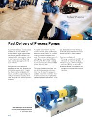
In several industrial processes, a fluid under high pressure must be throttled to suit subsequent<br />
process steps. Typically, conventional pressure-reducing valves are used to dissipate, and<br />
consequently waste, this hydraulic energy. Hydraulic power recovery turbines (HPRT’s) can<br />
convert the excess pressure into mechanical shaft energy and increase the overall process<br />
<strong>efficiency</strong>. Sulzer Pumps has years of experience in using reverse running pumps as turbines<br />
as an economical solution to recover energy.<br />
26<br />
| Sulzer Technical Review 1/2011<br />
Generally, pumps are a means of<br />
fluid transport that convert mechanical<br />
energy into hydraulic energy; i.e., pumps<br />
increase fluid pressure. When process<br />
conditions call for pressure to be dissipated,<br />
a pump running backwards may<br />
be used to capture that otherwise wasted<br />
energy. The reverse running mode<br />
converts hydraulic energy into mechanical<br />
energy and can be used to drive a<br />
generator or to assist the driver of other<br />
rotating machines. By using an HPRT,<br />
as much as 85% of the energy otherwise<br />
wasted in a throttling valve can be<br />
captured. When modified standard<br />
pumps are used as HPRTs, investment<br />
costs are low as compared with those<br />
for conventional turbines. Energy<br />
recovery may merit consideration even<br />
if the pressure reduction is relatively<br />
small.<br />
Almost any centrifugal pump can<br />
operate as a turbine. The direction of<br />
fluid flow is reversed compared with<br />
that in a pump. The pump discharge<br />
flange becomes the inlet of the HPRT,<br />
and the pump suction flange becomes<br />
the outlet, or exhaust. For larger HPRTs,<br />
the interior of the pump casing is<br />
modified to provide uniform flow to the<br />
runner.<br />
Energy recovery<br />
Conventional hydraulic turbines can be<br />
of axial, mixed, or radial flow type, and<br />
single or multistage. Differential head,<br />
flow, and speed govern which type is<br />
applied for a particular application. These<br />
three parameters determine the specific<br />
speed of a hydraulic machine. Specific<br />
speed is a characteristic number for each<br />
pump or turbine, and it increases with<br />
higher flow and lower head. High specific<br />
speed (axial flow) runners are used for<br />
lower head and higher flow, as in runof-river<br />
hydropower plants 1.<br />
Single-stage or multistage radial-flow<br />
or mixed-flow turbines are used for<br />
higher heads. For very low flow with<br />
high head, an impulse, or Pelton turbine<br />
may be an appropriate choice. The power<br />
output of a hydraulic power recovery<br />
device is a function of flow and head.<br />
Reaction type turbines are used for power<br />
ratings between 500 kW and about<br />
700 MW in hydropower plants.<br />
In some industrial installations, such<br />
as reverse osmosis plants, petroleum<br />
refineries, fertilizer plants, and gas<br />
treating facilities, some processes may<br />
need to operate at high pressure. For<br />
example, amine contactors are widely<br />
used to scrub CO2 and H2S from natural<br />
gas. The contactor operates at pipeline<br />
pressure. Then pressure is reduced to<br />
flash out various components of the<br />
process stream. Usually throttling devices<br />
(valves, orifices etc.) are used to reduce<br />
the pressure. Single-stage HPRTs can be<br />
used to recover that energy. In refining<br />
hydro treaters, multistage HPRTs may be<br />
needed due to the large pressure drop<br />
required.<br />
Know-how for correct layout<br />
When planning the use of a pump as<br />
turbine, it is essential to know the differences<br />
in machine performance when<br />
reversing flow direction and sense of<br />
rotation. For equal rotational speed and<br />
runner diameter, the following general<br />
differences are noted 2:<br />
• The <strong>efficiency</strong> at the best operating<br />
point of the turbine corresponds<br />
4335
approximately to that of the pump, or<br />
it can be slightly higher depending on<br />
the size of the machine.<br />
• The <strong>efficiency</strong> curve under overload<br />
conditions drops more slowly in the<br />
turbine than in the pump mode since<br />
the losses are associated with a high<br />
power.<br />
• The best <strong>efficiency</strong> point of the turbine<br />
is located at higher flow rate and higher<br />
head. That means the capacity is higher<br />
in the turbine mode than when<br />
pumping.<br />
• In most instances, the shaft power at<br />
the best operating point of the turbine<br />
is somewhat higher than that at the<br />
corresponding point of the pump.<br />
• Susceptibility to cavitation is lower in<br />
the turbine than in the pumping mode,<br />
since the low pressure zone is at the<br />
runner outlet in turbine mode.<br />
Sulzer has provided hundreds of HPRTs<br />
3 in various configurations and has<br />
established methods to calculate HPRT<br />
performance from pump performance.<br />
However, if exact data are necessary, it<br />
is essential to test the HPRT. Turbine<br />
testing requires a lot of equipment and<br />
thus costs measurably more than pump<br />
testing 4 .<br />
A booster pump with sufficient power<br />
must be used to provide the inlet flow<br />
and high inlet pressure. The output power<br />
of the HPRT must be measured with a<br />
calibrated generator, torque meter, or<br />
dynamometer. Measurements of power,<br />
flow, and pressure are used to calculate<br />
turbine <strong>efficiency</strong>. To avoid cavitation at<br />
the HPRT outlet, backpressure at the<br />
outlet must be controlled.<br />
Considering the complete system<br />
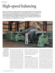
Determination of the runaway speed is<br />
essential for the operation of the reverse<br />
running pump. Runaway is the operation<br />
at maximum speed and no load.<br />
This is an exceptional case that occurs<br />
when the generator loses its grid connection<br />
due to a power outage or lightning<br />
strike. Runaway could occur in fractions<br />
of a second and has to be considered<br />
in the layout of a hydraulic system.<br />
Runaway speed of a radial machine<br />
0 1 2<br />
2<br />
0 2<br />
QPop: QTop:<br />
2 Characteristics of a pump impeller in pump<br />
and turbine mode (n = constant, D = constant).<br />
The best <strong>efficiency</strong> point (BEP) of the turbine<br />
is shifted to higher head and flow rate.<br />
1 Large water turbines can have a power rating of 700 MW or more. At much smaller ratings, conventional pumps running as turbines<br />
are an economical solution for pressure reduction in industrial processes.<br />
© Andrey Shchekalev | Dreamstime.com<br />
HT / HP<br />
1<br />
0<br />
PT / PP<br />
1<br />
0<br />
-0.5<br />
HT<br />
HP<br />
ηT<br />
ηP<br />
PT<br />
PP<br />
1<br />
ηT / ηP<br />
0<br />
QT/QP<br />
PANORAMA<br />
Pump<br />
Turbine<br />
Anticipation Range<br />
Sulzer Technical Review 1/2011 |<br />
27
PANORAMA<br />
3 In many cases, a single-stage HPRT is used to capture the process stream energy and drive a multistage pump.<br />
4 Typical HPRT test setup in a closed loop.<br />
Electric<br />
Power<br />
Supply<br />
Electric<br />
Power<br />
Grid<br />
Electrical<br />
Power<br />
Measurement<br />
Pump discharge<br />
pressure<br />
Pl<br />
Throttle valve<br />
Turbine inlet pressure<br />
can be between 140% and 200% of<br />
the nominal speed, depending on the<br />
specific speed and the rated conditions.<br />
This condition should be taken into<br />
account for generator operation and in<br />
the selection of the trip device that<br />
operates at transient conditions. If the<br />
HPRT is used to drive a generator, it<br />
may be prudent to use a gear reducer<br />
and drive the generator at four- or sixpole<br />
(1500 RPM or 1000 RPM at 50 Hz<br />
power frequency, 1800 RPM or 1200 RPM<br />
at 60Hz power frequency) speeds but<br />
mechanically design the generator rotor<br />
for two-pole speed (3000 RPM at 50 Hz,<br />
3600 RPM at 60Hz).<br />
Motor<br />
Pl Pl<br />
Electrical<br />
Power<br />
Measurement<br />
Booster<br />
Pump<br />
Turbine<br />
Generator<br />
P<br />
Pump suction<br />
pressure<br />
Suction<br />
valve<br />
Turbine outlet pressure<br />
28 | Sulzer Technical Review 1/2011<br />
Vacuum<br />
Pump<br />
Flow meter<br />
(Venturi or magnetic)<br />
Suppression<br />
Tank<br />
Flow<br />
Fluid temperature<br />
Air pressure<br />
supply<br />
Vent<br />
Fill<br />
Drain<br />
Back pressure<br />
valve<br />
Hydropower turbines have flow<br />
control devices, such as wicket gates,<br />
which help to avoid high pressure surge<br />
during transient conditions. In process<br />
HPRT applications, the turbine bypass<br />
is always slightly open and is quickly<br />
adjusted to maintain inlet vessel level<br />
control when the turbine inlet valve trips.<br />
Operating with two-phase flow<br />
Care must be taken when starting up an<br />
HPRT. When an HPRT is driving a generator,<br />
it is normally spun-up to near<br />
operating speed, and then as the speed<br />
nears synchronous speed, the generator<br />
is switched to the power grid, which<br />
provides a load. Without load, the HPRT<br />
may quickly overspeed.<br />
Process control is important when<br />
applying HPRTs. If the pressure in the<br />
exhaust vessel is lowered by 20%, head<br />
across the turbine increases, and it will<br />
generate 20% more power than at the<br />
rated flow and head. For that reason, it<br />
is often prudent to oversize the HPRTs,<br />
shaft torque capacity to take into account<br />
various system upsets in pressure control.<br />
Processes have to be started before the<br />
HPRT can be brought on stream. Often,<br />
there will be a full-size pump with motor<br />
driver to get the process started and a<br />
parallel HPRT clutch motor pump that<br />
is used during normal operation 5 6.<br />
For processes with entrained gas or<br />
vapor (natural gas treating, fertilizer<br />
plants, hydrotreaters, etc.), a small volume<br />
percent of gas at the high-pressure side<br />
will turn into a measurable volume at<br />
the low-pressure side. This gas volume<br />
at the outlet may influence the size of<br />
the HPRT. The high gas volume in the<br />
exhaust may not be an issue if the shaft<br />
is robust, the runner is made of cavitation-resistant<br />
materials, and the wear<br />
parts are hardened to reduce contact<br />
damage. However, gas bubbles in the<br />
seal chamber will surely do damage to<br />
the mechanical seals. Dual seals within<br />
Plan 53 or 54 are therefore recommended<br />
for process HPRTs to assure that the<br />
mechanical seals operate in a controlled,<br />
liquid state.<br />
Application in hydrocarbon<br />
processing<br />
A large Brazilian oil company is using<br />
pumps as turbines instead of throttle<br />
valves and is thus recovering energy.<br />
In one case, liquid charged with gas<br />
must be expanded in a scrubbing tower.<br />
Sulzer worked with oil company engineers<br />
to understand the multiphase flow.<br />
That knowledge was then used to design<br />
the HPRT’s runner and rotor. The experience<br />
of Sulzer Pumps in designing such<br />
HPRTs helped to find a solution for these<br />
challenging conditions.<br />
Between the inlet and outlet of a<br />
turbine, the pressure drops in very short<br />
time. Gas dissolved in the fluid at high<br />
pressure diffuses out of the liquid causing<br />
gas bubbles to form, resulting in twophase<br />
flow. The required pressure reduction<br />
is from 74.8 bar (1080 psi) to 14.8bar<br />
(210psi). A five-stage HPRT with one<br />
dummy stage was chosen, so that a<br />
further stage may be fitted for smaller<br />
flow rates in the future 7. The continuous<br />
power of 258 kW recovered from the<br />
expansion assists the 870-kW motor<br />
driving the pressure <strong>increasing</strong> pump. A<br />
pump running as a turbine is difficult<br />
5 HPRT equipment layout: Driving the<br />
generator at reduced speed can save it on<br />
overspeed caused by a sudden power loss.<br />
Pump<br />
HPRT<br />
Gear<br />
reducer<br />
Motor<br />
Clutch<br />
Generator<br />
HPRT
6 Some HPRT trains are so long that the baseplate is split at one coupling to facilitate<br />
shipping, lifting, and installation. Setup: HT-MSD – clutch – motor (missing) – MSD pump.<br />
to regulate. Depending upon the pressure<br />
drop and application, an HPRT flow<br />
rate may be established amounting to<br />
80%–90% of the effective throughput.<br />
The remaining 10%–20% of the flow is<br />
expanded via a bypass valve and is used<br />
to control the vessel level supplying the<br />
HPRT.<br />
During plant startup, the turbine<br />
cannot perform work and may actually<br />
8 Gas plant: MSD pump – motor – clutch – HST turbine.<br />
consume energy. If the motor must be<br />
used for startup, an overrunning clutch<br />
prevents the motor from having to put<br />
additional energy into the turbine during<br />
this phase. Once the hydraulic energy<br />
at the inlet to the HPRT is sufficient, the<br />
turbine runs up to the motor speed. The<br />
overrunning clutch now ensures that the<br />
HPRT cannot run faster and supplies its<br />
hydraulic energy to the drive train.<br />
Amine<br />
contactor<br />
Startup<br />
pump<br />
Level controller<br />
Sour gas<br />
Startup<br />
motor<br />
Sweet gas stream<br />
Pump Motor<br />
Bypass<br />
Lean amine stream<br />
7 A gas-scrubbing HPRT application can recover more than 2 MW.<br />
Clutch<br />
Short payback times<br />
In many industrial processes, hydraulic<br />
power recovery turbines (HPRTs 8 )<br />
can provide substantial savings with a<br />
short payback period. It is not uncommon<br />
to find that over 1.5MW can be re -<br />
covered. Careful attention to process<br />
conditions and HPRT controls assures<br />
reliable, useful operation for years of<br />
service.<br />
HPRT<br />
PANORAMA<br />
Stripper<br />
Ron Adams<br />
Sulzer Pumps<br />
800 Koomey Road<br />
Brookshire, TX 77423<br />
USA<br />
Phone +1 281 934 6029<br />
ron.adams@sulzer.com<br />
John Parker<br />
Sulzer Pumps<br />
800 Koomey Road<br />
Brookshire, TX 77423<br />
USA<br />
Phone +1 281 934 6011<br />
johns.parker@sulzer.com<br />
Sulzer Technical Review 1/2011 |<br />
29