Advanced Modulation For High Data Rate Optical ... - Infinera
Advanced Modulation For High Data Rate Optical ... - Infinera
Advanced Modulation For High Data Rate Optical ... - Infinera

Create successful ePaper yourself
Turn your PDF publications into a flip-book with our unique Google optimized e-Paper software.
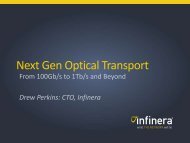
<strong>Advanced</strong> <strong>Modulation</strong> <strong>For</strong> <strong>High</strong><br />
<strong>Data</strong> <strong>Rate</strong> <strong>Optical</strong> Transmission:<br />
100G and Beyond<br />
Leigh Wade, <strong>Infinera</strong>
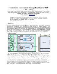
The State of the Market Today<br />
800G<br />
• 10Gb/s<br />
• NRZ<br />
• C-band<br />
80 ch. @ 10G = 800G<br />
More<br />
channels<br />
<strong>High</strong>er<br />
<strong>Data</strong> <strong>Rate</strong>s<br />
More<br />
Spectrum<br />
I will propose that photonic integration<br />
is an excellent solution to all three<br />
capacity challenges
Lower Cost per Bit<br />
Why do we need<br />
more than 800G?<br />
<strong>High</strong>er Speed Services<br />
More Capacity
Cost per Usable Bit<br />
Fiber Exhaust & Network Economics<br />
10G λ<br />
40G λ<br />
You want to move<br />
to 40G here…<br />
Excess<br />
cost<br />
100G λ<br />
…but what if you hit<br />
fiber exhaust here?<br />
Time<br />
Fiber exhaust can force uneconomic network decisions
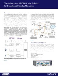
Double Density Optics Mean Investment Protection<br />
and “Option Value”<br />
Conventional 80-96 λ WDM<br />
<strong>Infinera</strong> “Double Density” WDM<br />
1 λ per 50 GHz<br />
800G in the C-band<br />
1 λ per 25 GHz<br />
1.6T in the C-band<br />
At 40% bandwidth growth, double-density optics mean<br />
two more years to select the lowest cost transmission.
Why doesn’t everybody offer Double Density?<br />
Two basic reasons:<br />
WSS ROADMs<br />
designed<br />
around 50GHz<br />
spacing<br />
Operational challenge of 160 discrete<br />
transponders on a single fiber!!
What are you going to see?<br />
Adding a single PICbased<br />
line card, with<br />
10x10Gb/s waves<br />
100Gb/s of capacity for<br />
the same effort as one<br />
10Gb/s transponder<br />
“Gaps” for<br />
additional waves<br />
<strong>Optical</strong><br />
Spectrum<br />
Analyzer<br />
Existing 10G waves<br />
on the fiber<br />
Stopwatch
PICs reduce operational burden by 10x<br />
But the rest of the optical industry<br />
does not have access to PICs so…<br />
They are under pressure to move to<br />
40G and 100G as soon as possible<br />
Not necessarily when it’s economical!
100G Technology Features<br />
Differentiators<br />
3<br />
2<br />
1<br />
Core Switching & Grooming<br />
Large Scale PICs<br />
Photonic Integration<br />
Table<br />
Stakes<br />
<strong>Advanced</strong><br />
<strong>Modulation</strong><br />
Fiber Capacity<br />
Coherent<br />
Detection<br />
<strong>High</strong> Gain FEC
Complex modulation requires<br />
complex optical circuits
Why do I need Complex <strong>Modulation</strong>?<br />
<strong>Optical</strong> transmission is about:<br />
• Sending high data rates<br />
• Over very long distances<br />
• <strong>For</strong> very little money<br />
Our biggest problem is optical fiber:<br />
• Loss<br />
• Dispersion<br />
• Modal dispersion<br />
• Chromatic dispersion<br />
• Polarization mode dispersion<br />
• Non-linear effects<br />
• Self phase modulation<br />
• Cross phase modulation<br />
• Four wave mixing<br />
If you stress any one of these variables, the<br />
others will respond<br />
<strong>For</strong> a given modulation type, the<br />
gross magnitude of these<br />
impairments scales roughly with<br />
the square of the symbol rate
Think of a light wave...<br />
Oscillating wave<br />
Wavelength<br />
• 1550nm<br />
Frequency<br />
• 193.1 THz<br />
Electronics is about 20,000 times<br />
“too slow” for direct detection of<br />
“wave properties”<br />
“State of the shelf”<br />
electronics can process at<br />
~10GHz
So how do we encode and detect signals on<br />
an optical carrier?<br />
Historically, used amplitude modulation<br />
Measures the strength of a large number of waves<br />
On/Off Keying (OOK) may interpret the presence of a<br />
signal as a “1”, and the absence of a symbol as a “0”
1 bit per symbol: NRZ <strong>Modulation</strong><br />
Rx<br />
Laser<br />
Modulator<br />
Detector<br />
NRZ<br />
Tx<br />
Simple modulation technique<br />
Easy to implement<br />
Low power use<br />
But very sensitive to fiber impairments<br />
as bitrate increases<br />
• This is what we’re talking about with the “square”<br />
relationship<br />
Increasing power will trigger non-linear<br />
effects
Phase Shift Keying<br />
In-phase Out of phase Interference<br />
patterns<br />
Phase is fundamental property of waves<br />
• Two waves in-phase when the peaks & troughs line up<br />
• We say that such waves are coherent<br />
• If non-coherent waves combine we see:<br />
• Reinforcement, cancellation, interference<br />
Interference can be used to extract a lower frequency<br />
modulation from a high frequency carrier
Using Phase to Apply a Signal<br />
Tx<br />
Laser generates a<br />
constant carrier<br />
LD<br />
MZI<br />
The carriers travel<br />
over different paths<br />
When the carriers<br />
recombine they will<br />
“contain” the data signal<br />
encoded as a series of<br />
phase changes<br />
The carrier is<br />
split into 2<br />
S<br />
Can apply a data signal,<br />
S, to vary the delay on<br />
one of the arms<br />
Rx Q:<br />
How do we recover the data signal at the receiver?<br />
Hold that thought!
Component Complexity<br />
Tx<br />
Rx<br />
Part 1<br />
The Transmitter
ODB <strong>Modulation</strong> (<strong>Optical</strong> Duo-Binary)<br />
Rx<br />
Laser MZ Modulator<br />
Detector<br />
ODB<br />
Tx<br />
First generation 40G modulation scheme<br />
Phase & Amplitude based modulation<br />
• Requires MZ modulator<br />
• Can use simple, direct detection<br />
Much more tolerant of dispersion<br />
Limited reach<br />
Widely used by 1st Gen 40G<br />
• Stratalight, Mintera
1 bit per symbol: DPSK<br />
1 0<br />
Re{Ex}<br />
Most basic phase modulation technique<br />
Differential technique allows phase slips to be ignored<br />
Used by OpNext & Mintera, and their OEMs<br />
AKA: BPSK, where local oscillator coherent detection is used
2 bits per symbol: Quadrature PSK<br />
<strong>Advanced</strong> modulation, 4 phase states = 2 bits<br />
More bits per symbol
2 bits per symbol: Quadrature PSK<br />
1,1<br />
0,1<br />
1,0<br />
0,0<br />
<strong>Advanced</strong> modulation, 4 phase states = 2 bits<br />
More bits per symbol
3 bits per symbol: 8-PSK<br />
...And higher orders of modulation<br />
0,1,1<br />
0,1,0<br />
1,1,0<br />
0,0,1<br />
1,1,1<br />
0,0,0<br />
1,0,0<br />
1,0,1<br />
8 phase states = 3 bits<br />
Twice as complex, but only 50% more bits<br />
<strong>For</strong> discrete implementations, 8-PSK seems to be too complex
The Law of Diminishing Returns<br />
Phase States vs Component Complexity<br />
Complexity Factor<br />
Let’s set a circuit complexity factor of 1, to be the<br />
equivalent of a simple DPSK transponder<br />
9<br />
8<br />
7<br />
Is there a better way to<br />
get to more bit/Hz?<br />
16x<br />
32x 9<br />
8<br />
7<br />
6<br />
6<br />
Bit/Hz<br />
5<br />
4<br />
5<br />
4<br />
3<br />
3<br />
2<br />
2<br />
1<br />
1<br />
DPSK (D)QPSK 8-PSK 16-QAM 32-QAM 64-QAM
PM-QPSK, 4 bits per “symbol”<br />
Two Polarizations<br />
Im{E x }<br />
Im{E x }<br />
Re{E x }<br />
X-Polarization<br />
Re{E x }<br />
Im{E y }<br />
Re{E y }<br />
Y-Polarization
Implementing Phase <strong>Modulation</strong> Using Discrete<br />
<strong>Optical</strong> Components...<br />
S
Implementing Phase <strong>Modulation</strong> Using Discrete<br />
<strong>Optical</strong> Components...<br />
S
This is QPSK...<br />
Im{E x }<br />
S1<br />
Re{E x }<br />
This structure called a “Super Mach Zehnder”<br />
S2
This is a PM-QPSK Transmitter<br />
X Polarizations<br />
LD<br />
PBS<br />
Y Polarizations
Component Complexity<br />
Tx<br />
Rx<br />
Part 2<br />
The Detector
Let’s cut to the chase…<br />
The only practical, long haul 100G implementations will<br />
be required to use Coherent Detection<br />
What is it, and why is it useful?
What is “coherent detection”?<br />
Physics definition<br />
• A detection technique that is based on the phase properties<br />
of the carrier<br />
• If you are using a phase-based detector, you could claim to<br />
be implementing coherent detection<br />
…however…<br />
Practical definition<br />
• The market has now come to expect a “coherent detector” to<br />
make use of sophisticated, digital signal processing (DSP)<br />
algorithms
Conventional WDM Detection<br />
How do we select the<br />
channel we want to detect?<br />
PD<br />
Mixture of waves on fiber…<br />
…wideband detector
Conventional WDM Detection<br />
Wavelength demux<br />
PD<br />
Mixture of waves on fiber…<br />
…wideband detector
Conventional WDM Detection<br />
Wavelength demux<br />
Direct conversion<br />
of photons into<br />
electrons that<br />
“look like” bits<br />
PD<br />
…11010110…
Summary of “Conventional WDM Detection”<br />
Wideband Photodetector (PD) is used<br />
To prevent inter-channel interference, a wavelength<br />
demux is used to spatially separate channels<br />
<strong>Modulation</strong> technique allows minimal Rx circuit<br />
complexity – essentially “direct detection”<br />
No additional signal processing normally required
Coherent WDM Detection<br />
We could take a mixed signal that uses a<br />
phase-based modulation technique<br />
LO<br />
PD<br />
ADC<br />
DSP<br />
Use a local oscillator to choose the<br />
“color” we want to “detect”
Coherent WDM Detection<br />
Convert the<br />
photons to<br />
electrons<br />
Clean it all up!<br />
LO<br />
PD<br />
ADC<br />
DSP<br />
…11010110…<br />
Convert the<br />
“analog electrons”<br />
into “digital<br />
electrons”
Why phase-based modulation?<br />
If you need to detect 5 from 1…n, then choose a<br />
local oscillator tuned to 5<br />
Local oscillator does not carry a signal – simply a<br />
continuous beam of light<br />
But it is non-coherent with the received signal (ie. it is<br />
out of phase)<br />
Use an array of interferometers to “measure” the<br />
interference patterns<br />
Convert the interference patterns into an electronic<br />
signal, and “process it”
The Detector Requires a Complex <strong>Optical</strong> Circuit<br />
Example: <strong>For</strong> PM-QPSK <strong>Modulation</strong>…<br />
PD<br />
PM-QPSK Signal<br />
PBS<br />
PD<br />
PD<br />
The signals that come<br />
out of the PD array are<br />
“analog and dirty”<br />
PD<br />
LO<br />
PBS
Two very different functions in the detector<br />
Phase state<br />
extraction<br />
• Separate the polarization components<br />
• Create interference against a<br />
reference laser (local oscillator)<br />
• Separate the phase components<br />
• PD & A/D conversion<br />
Signal processing<br />
• Compensate for local oscillator<br />
instability<br />
• Compensate for static CD<br />
• Compensate for dynamic PMD
How do we implement these functions?<br />
Sophisticated<br />
optical circuit<br />
(PIC)<br />
• Separate the polarization components<br />
• Create interference against a<br />
reference laser (local oscillator)<br />
• Separate the phase components<br />
• PD & A/D conversion<br />
Sophisticated digital<br />
signal processing<br />
(DSP)<br />
• Compensate for local oscillator<br />
instability<br />
• Compensate for static CD<br />
• Compensate for dynamic PMD
DSP<br />
A Coherent Detector Schematic<br />
(<strong>For</strong> one wavelength only)<br />
<strong>Optical</strong> Circuit<br />
Electronic Circuit<br />
Incoming carrier<br />
(2 polarizations, each<br />
with 4 phase states)<br />
AMZ<br />
PD<br />
ADC<br />
PBS<br />
AMZ<br />
PD<br />
ADC<br />
LO<br />
PBS<br />
AMZ<br />
PD<br />
ADC<br />
ADC A/D Converter<br />
AMZ Adjustable Mach Zehnder<br />
DSP Digital Signal Processor<br />
LO Local Oscillator<br />
PD Photo Detector<br />
PS Polarization Splitter<br />
AMZ<br />
PD<br />
ADC
A Coherent Detector Schematic<br />
(<strong>For</strong> one wavelength only)<br />
DSP<br />
<strong>Optical</strong> Circuit<br />
Electronic Circuit<br />
Incoming carrier<br />
(2 polarizations, each<br />
with 4 phase states)<br />
AMZ<br />
PD<br />
ADC<br />
1<br />
LO<br />
PBS<br />
PBS<br />
AMZ<br />
AMZ<br />
PD<br />
PD<br />
ADC<br />
ADC<br />
ADC A/D Converter<br />
AMZ Adjustable Mach Zehnder<br />
DSP Digital Signal Processor<br />
LO Local Oscillator<br />
PD Photo Detector<br />
PS Polarization Splitter<br />
AMZ PD ADC<br />
Step 1: Take the two optical sources – signal and local oscillator
A Coherent Detector Schematic<br />
(<strong>For</strong> one wavelength only)<br />
DSP<br />
<strong>Optical</strong> Circuit<br />
Electronic Circuit<br />
Incoming carrier<br />
(2 polarizations, each<br />
with 4 phase states)<br />
AMZ<br />
PD<br />
ADC<br />
LO<br />
PBS<br />
2<br />
PBS<br />
AMZ<br />
AMZ<br />
PD<br />
PD<br />
ADC<br />
ADC<br />
ADC A/D Converter<br />
AMZ Adjustable Mach Zehnder<br />
DSP Digital Signal Processor<br />
LO Local Oscillator<br />
PD Photo Detector<br />
PS Polarization Splitter<br />
AMZ PD<br />
Step 2: Separate the X and Y polarizations<br />
ADC
A Coherent Detector Schematic<br />
(<strong>For</strong> one wavelength only)<br />
DSP<br />
<strong>Optical</strong> Circuit<br />
Electronic Circuit<br />
Incoming carrier<br />
(2 polarizations, each<br />
with 4 phase states)<br />
AMZ<br />
PD<br />
ADC<br />
LO<br />
PBS<br />
PBS<br />
AMZ<br />
3<br />
AMZ<br />
PD<br />
PD<br />
ADC<br />
ADC<br />
ADC A/D Converter<br />
AMZ Adjustable Mach Zehnder<br />
DSP Digital Signal Processor<br />
LO Local Oscillator<br />
PD Photo Detector<br />
PS Polarization Splitter<br />
AMZ PD ADC<br />
Step 3: Generate a set of interference patterns in the SMZ array
A Coherent Detector Schematic<br />
(<strong>For</strong> one wavelength only)<br />
DSP<br />
<strong>Optical</strong> Circuit<br />
Electronic Circuit<br />
Incoming carrier<br />
(2 polarizations, each<br />
with 4 phase states)<br />
AMZ<br />
PD<br />
ADC<br />
LO<br />
PBS<br />
PBS<br />
AMZ<br />
AMZ<br />
PD<br />
4<br />
PD<br />
ADC<br />
ADC<br />
ADC A/D Converter<br />
AMZ Adjustable Mach Zehnder<br />
DSP Digital Signal Processor<br />
LO Local Oscillator<br />
PD Photo Detector<br />
PS Polarization Splitter<br />
AMZ PD ADC<br />
Step 4: Convert optical signals to analog electronic signals
A Coherent Detector Schematic<br />
(<strong>For</strong> one wavelength only)<br />
DSP<br />
<strong>Optical</strong> Circuit<br />
Electronic Circuit<br />
Incoming carrier<br />
(2 polarizations, each<br />
with 4 phase states)<br />
AMZ<br />
PD<br />
ADC<br />
LO<br />
PBS<br />
PBS<br />
AMZ<br />
AMZ<br />
PD<br />
PD<br />
ADC<br />
ADC<br />
5<br />
ADC A/D Converter<br />
AMZ Adjustable Mach Zehnder<br />
DSP Digital Signal Processor<br />
LO Local Oscillator<br />
PD Photo Detector<br />
PS Polarization Splitter<br />
AMZ PD ADC<br />
Step 5: Convert analog to digital and process
Coherent Detection – Pros and Cons<br />
Pros:<br />
• Operates over the existing fiber plant and amp chains<br />
• Outstanding reach performance<br />
• Closest thing to achieving 40G and 100G with same reach as 10G NRZ<br />
• Significant pilot test results indicate it really does work!<br />
Cons:<br />
• Potential non-linear interaction with 10G NRZ in same fiber<br />
• The “cure” is managing launch power<br />
• Probably represents the practical complexity limit for discretes<br />
• State of the shelf DSP technology draws too much power to allow for large<br />
scale implementations (ie. multiple waves in one modules)<br />
• Solution is to use emerging 40µm DSP technology<br />
• DSP operation probably eliminates the chance of future line side interop
So remember…<br />
Complex modulation requires<br />
complex optical circuits
Where have we seen this problem before?<br />
• In the 1950s computers were made from individual<br />
transistors, resistors and capacitors...<br />
…today?
The electronics industry controlled component<br />
complexity with large scale integration<br />
We know the same thing works for optical<br />
components – we did it 5 years ago!
Small Scale vs Large Scale Photonic Integration<br />
Small Scale…<br />
• Operates on a single wavelength<br />
• Primarily used to address manufacturing cost<br />
If it works for one wave, why not…<br />
CPUs with 2-8 cores<br />
GPUs with 200-800 cores!!
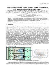
<strong>Infinera</strong> 100G Transmission Differentiators<br />
500G, Large Scale, Monolithic PIC Implementation<br />
COST<br />
CAPACITY<br />
RELIABILITY<br />
500G<br />
Tx PIC<br />
500G<br />
Rx PIC<br />
SIZE<br />
POWER<br />
Number of channels<br />
5 x 100G<br />
Monolithic InP Chips 2<br />
<strong>Optical</strong> elements > 600<br />
“Gold Box” Replacements > 100<br />
Fiber Replacements > 400<br />
54 © 2011 <strong>Infinera</strong> Corporation Confidential & Proprietary
Fat Pipes Are Not Enough<br />
How much capacity can<br />
actually be used?
<strong>Infinera</strong> 100G Transmission Differentiators<br />
PICs Enable Pervasive Digital Switching<br />
Photonic<br />
Integration<br />
100 Gb/s Transmit<br />
100 Gb/s Receive<br />
PICs enable<br />
cost-effective OEO<br />
100Gb/s to 1Tb/s “WDM<br />
system on a chip”<br />
Affordable access to<br />
digital domain<br />
56 © 2011 <strong>Infinera</strong> Corporation Confidential & Proprietary
<strong>Infinera</strong> 100G Transmission Differentiators<br />
PICs Enable Pervasive Digital Switching<br />
Integrated Photonics<br />
Integrated Photonics<br />
<strong>Optical</strong> (O) Electrical (E) <strong>Optical</strong> (O)<br />
Photonic<br />
Integration<br />
Integrated<br />
Switching + WDM<br />
100101011101010000101011<br />
100101010101101011010101<br />
110101000010101110010101<br />
001010111011010110010101<br />
1001<br />
0101<br />
Trib<br />
0101<br />
1010<br />
1101<br />
0101<br />
0101<br />
1010<br />
Enables “digital” functionality<br />
1101<br />
0101<br />
Integrated switching at every node<br />
<strong>High</strong> functionality Digital ROADM<br />
Dramatic network simplification<br />
57 © 2011 <strong>Infinera</strong> Corporation Confidential & Proprietary
<strong>Infinera</strong> 100G Transmission Differentiators<br />
PICs Enable Pervasive Digital Switching<br />
Integrated Photonics<br />
Integrated Photonics<br />
10010101110101010000<br />
10010101010110101011<br />
end-end service<br />
Photonic<br />
Integration<br />
Integrated<br />
Switching + WDM<br />
Pervasive Digital<br />
Switching<br />
10010101110101010000<br />
10010101010110101011<br />
100101011101010000101011<br />
100101010101101011010101<br />
110101000010101110010101<br />
001010111011010110010101<br />
1001<br />
0101<br />
0101<br />
1010<br />
1101<br />
0101<br />
0101<br />
1010<br />
1101<br />
Software-based “Ease-of-Use”<br />
0101<br />
Digital OTN switching at every node<br />
Unconstrained bandwidth everywhere<br />
Lowest cost per switched Gb/s<br />
58 © 2011 <strong>Infinera</strong> Corporation Confidential & Proprietary
Muxponder<br />
Solving The 100G Muxponder Tax<br />
The Problem:<br />
• Backbone waves move to 100G, but service demands still 10G or lower<br />
• All-optical ROADMs have no inter-wavelength, or sub-wavelength<br />
grooming capability → 100G muxponders!<br />
Service Demands:<br />
A ↔ C<br />
Require Extra,<br />
Partially Filled<br />
A ↔ D Muxponder Pairs<br />
10GbE<br />
10GbE<br />
Muxponder<br />
ROADM Network<br />
B<br />
B<br />
↔<br />
↔<br />
C<br />
D<br />
10GbE<br />
10GbE<br />
How big is the<br />
“Muxponder Tax”<br />
in a real 100G<br />
network?<br />
A<br />
All services must go A ↔B<br />
B<br />
59<br />
© 2011 <strong>Infinera</strong> Corporation Confidential & Proprietary
Deployed Capacity (%)<br />
Revenue Generating (%)<br />
<strong>Infinera</strong> National Network Model Summary<br />
50%<br />
66%<br />
92%<br />
100<br />
90<br />
80<br />
70<br />
60<br />
50<br />
40<br />
30<br />
20<br />
10<br />
100<br />
90<br />
80<br />
70<br />
60<br />
50<br />
40<br />
30<br />
20<br />
10<br />
100G<br />
Muxponder<br />
40G<br />
Muxponder<br />
<strong>Infinera</strong> Digital<br />
ROADM<br />
• Large N. Am. Network Model: 33,084 route km, 47 core WDM links<br />
• About 10 Tb/s of customer service demands (network traffic volume)<br />
60<br />
© 2011 <strong>Infinera</strong> Corporation Confidential & Proprietary
Summary of Network Efficiency<br />
A “Perfect Storm” is emerging in terms of network<br />
bandwidth efficiency:<br />
• Wavelength speeds moving to 100Gbit/s<br />
• Majority of services demands remaining at 10Gbit/s or less for near-term<br />
• All-optical ROADMs have no effective way to offer contentionless<br />
wavelength conversion and sub-wavelength grooming in the core<br />
• Muxponders are simply point-point aggregators and do not do grooming<br />
The result is that a Service Provider may need to<br />
purchase 2X Network Capacity for 1X Service Revenue<br />
The solution is an Integrated Digital OTN Network with:<br />
Bandwidth<br />
Virtualization<br />
• End to End, Any to Any service capability<br />
• Integrated OTN switching and grooming in the core<br />
• End to End intelligent optical control plane
Beyond 8Tb/s?<br />
8Tb/s<br />
More<br />
channels<br />
<strong>High</strong>er<br />
<strong>Data</strong> <strong>Rate</strong>s<br />
More<br />
Spectrum<br />
Gridless Super-<br />
Channels<br />
Even more complex<br />
modulation!<br />
L-Band<br />
S-Band<br />
E-Band<br />
O-Band<br />
Outside the scope of this discussion
What’s changed so far<br />
Since the advent of DWDM…<br />
Intensity <strong>Modulation</strong><br />
Direct Detection<br />
ITU Frequency Grid<br />
Phase <strong>Modulation</strong><br />
Coherent Detection<br />
ITU Frequency Grid<br />
now<br />
63 © 2011 <strong>Infinera</strong> Corporation Confidential & Proprietary
What Comes Next <strong>For</strong> Terabit Transport?<br />
Since the advent of DWDM…<br />
Intensity <strong>Modulation</strong><br />
Direct Detection<br />
ITU Frequency Grid<br />
Quadrature Amplitude<br />
Phase<br />
<strong>Modulation</strong><br />
<strong>Modulation</strong><br />
(QAM)<br />
Coherent Wave Combining<br />
and Separation<br />
Detection<br />
ITU Grid-less Frequency FlexChannels Grid<br />
…so what has to change<br />
64 © 2011 <strong>Infinera</strong> Corporation Confidential & Proprietary
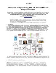
Capacity * Reach Product<br />
<strong>Advanced</strong> <strong>Modulation</strong> <strong>For</strong>mats<br />
Pol-Mux<br />
QPSK<br />
Pol-Mux<br />
8-QAM<br />
1.2<br />
1<br />
PM-<br />
BPSK<br />
Pol-Mux<br />
16-QAM<br />
0.8<br />
0.6<br />
0.4<br />
0.2<br />
0<br />
IM-DD<br />
1.6 8 12 16 24<br />
65 © 2011 <strong>Infinera</strong> Corporation Confidential & Proprietary<br />
C-Band Capacity (Tb/s)
What Comes Next <strong>For</strong> Terabit Transport?<br />
Since the advent of DWDM…<br />
On-Off Keyed <strong>Modulation</strong><br />
Direct Detection<br />
ITU Frequency Grid<br />
Quadrature Amplitude<br />
<strong>Modulation</strong><br />
Coherent Wave Separation<br />
Grid-less FlexChannels<br />
…so what has to change<br />
66 © 2011 <strong>Infinera</strong> Corporation Confidential & Proprietary
Single Carrier vs Multi-Carrier<br />
Goal: Create a 1Tb/s unit of transmission capacity<br />
How?<br />
Option 1:<br />
Build a singlecarrier<br />
1Tb/s<br />
channel<br />
Option 2:<br />
Build a multicarrier<br />
1Tb/s<br />
“super-channel”<br />
67<br />
© 2011 <strong>Infinera</strong> Corporation Confidential & Proprietary
OSNR Penalty (dB)<br />
1Tb/s Single Carrier: The A/D Converter Problem<br />
10<br />
9<br />
8<br />
7<br />
6<br />
5<br />
4<br />
3<br />
2<br />
1<br />
By 2014 commercial ADCs are<br />
expected to operate at ~64GBaud<br />
PM-BPSK<br />
640GBaud<br />
PM-8QAM<br />
210GBaud<br />
PM-QPSK<br />
320GBaud<br />
PM-16QAM<br />
160GBaud<br />
PM-64QAM<br />
105GBaud<br />
PM-32QAM<br />
128GBaud<br />
1 2 4 6 8 10 12<br />
Number of bits per symbol<br />
68<br />
© 2011 <strong>Infinera</strong> Corporation Confidential & Proprietary
DWDM Direct Detection<br />
Spatially separate the<br />
channels using a<br />
wavelength demux<br />
Spacing on the fiber<br />
needed between waves:<br />
“Guard Bands”<br />
PD<br />
wavelength<br />
demux<br />
69 © 2011 <strong>Infinera</strong> Corporation Confidential & Proprietary
DWDM Coherent Detection<br />
Spatially separate the<br />
channels using a<br />
wavelength demux<br />
Spacing on the fiber<br />
needed between waves:<br />
“Guard Bands”<br />
LO<br />
PD<br />
ADC<br />
DSP<br />
wavelength<br />
demux<br />
Use a local oscillator to<br />
choose the “color” we want<br />
to “detect” to match the<br />
demux port color<br />
70 © 2011 <strong>Infinera</strong> Corporation Confidential & Proprietary
How 1Tb/s Might Look…<br />
Conventional WDM vs FlexChannels<br />
Conventional Per-Channel<br />
WDM Filtering<br />
1Tb/s<br />
Guard bands to allow for<br />
individual wavelength demux<br />
Multi-Carrier FlexChannel<br />
1Tb/s<br />
Fewer guard-bands<br />
25% increase in useable<br />
amplifier spectrum<br />
71 © 2011 <strong>Infinera</strong> Corporation Confidential & Proprietary
What Comes Next <strong>For</strong> Terabit Transport?<br />
Since the advent of DWDM…<br />
On-Off Keyed <strong>Modulation</strong><br />
Direct Detection<br />
ITU Frequency Grid<br />
Quadrature Amplitude<br />
<strong>Modulation</strong><br />
Coherent Wave Separation<br />
Grid-less FlexChannels<br />
…so what has to change<br />
72 © 2011 <strong>Infinera</strong> Corporation Confidential & Proprietary
FlexChannels Increase Total Fiber Capacity<br />
More complex modulation → more capacity per fiber<br />
PM-QPSK<br />
12 Tb/s<br />
8-QAM<br />
18 Tb/s<br />
1Tb/s<br />
16-QAM<br />
25 Tb/s<br />
73 © 2011 <strong>Infinera</strong> Corporation Confidential & Proprietary
Reach, Spectral Efficiency, and Co-Existence<br />
A<br />
B<br />
C<br />
D<br />
E<br />
10x100G PM-QPSK<br />
1Tb/s PM-QPSK<br />
FlexChannel<br />
1Tb/s PM-8QAM<br />
FlexChannel<br />
1Tb/s PM-16QAM<br />
FlexChannel<br />
or<br />
74 © 2011 <strong>Infinera</strong> Corporation Confidential & Proprietary
Summary:<br />
The Key Technologies <strong>For</strong> 1Tb/s Are Well Understood<br />
But the implementation of those technologies will be<br />
critical to allowing service providers to differentiate their<br />
products and services<br />
Differentiators<br />
3<br />
2<br />
1<br />
Pervasive, Switched DWDM<br />
FlexCoherent <strong>Modulation</strong><br />
Large Scale PICs<br />
Foundation<br />
Features<br />
<strong>Advanced</strong><br />
<strong>Modulation</strong><br />
Coherent<br />
Processing<br />
<strong>Advanced</strong><br />
FEC<br />
75 © 2011 <strong>Infinera</strong> Corporation Confidential & Proprietary
Thank You!<br />
lwade@infinera.com<br />
© 762011<br />
<strong>Infinera</strong> Corporation Confidential & Proprietary