1B.7âLightning and Other Overvoltage Protection - Pacific Power
1B.7âLightning and Other Overvoltage Protection - Pacific Power
1B.7âLightning and Other Overvoltage Protection - Pacific Power

Create successful ePaper yourself
Turn your PDF publications into a flip-book with our unique Google optimized e-Paper software.
Volume 1—General<br />
Part B—Operability <strong>and</strong> Reliability Guidelines<br />
Section 7—Lightning <strong>and</strong> <strong>Other</strong> <strong>Overvoltage</strong> <strong>Protection</strong><br />
1B.7—Lightning <strong>and</strong> <strong>Other</strong> <strong>Overvoltage</strong> <strong>Protection</strong><br />
1 Scope<br />
This Engineering H<strong>and</strong>book document describes the overvoltage protection requirements for<br />
substations <strong>and</strong> transmission lines. These are general requirements <strong>and</strong> refer to PacifiCorp’s<br />
Construction St<strong>and</strong>ards for more specific information. References are also made to pertinent<br />
industry st<strong>and</strong>ards where applicable. These protection policies are intended to cover<br />
overvoltages due to lightning, switching surges, ferroresonance, <strong>and</strong> temporary overvoltages<br />
caused by faults.<br />
2 General<br />
Recent reviews of distribution <strong>and</strong> substation lightning protection practices at PacifiCorp<br />
have shown that additional overvoltage protection is warranted in some service areas. The<br />
latest revision of EA 111 describes new practices that apply to distribution. The substation<br />
guidelines put forth in this document will be further developed as the need arises with new<br />
construction, or when specific areas are identified for immediate attention to overvoltage<br />
potential. St<strong>and</strong>ards for the most common substations, such as 138−12.47 kV, will be<br />
developed first.<br />
3 References <strong>and</strong> Resource Documents<br />
The reference <strong>and</strong> resource documents listed below apply to the extent specified in these<br />
policies <strong>and</strong> in the referenced st<strong>and</strong>ards:<br />
IEEE St<strong>and</strong>ard 998−1996, IEEE Guide for Direct Lightning Stroke Shielding of Substations<br />
IEEE St<strong>and</strong>ard 1313.2−1999, IEEE Guide for the Application of Insulation Coordination<br />
IEEE St<strong>and</strong>ard 1410−1997, IEEE Guide for Improving the Lightning Performance of Electric<br />
<strong>Power</strong> Overhead Distribution Lines<br />
Hileman, Andrew R., Insulation Coordination for <strong>Power</strong> Systems, Copyright 1999, Marcel<br />
Dekker, Inc.<br />
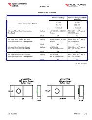
4 Ground Flash Density Levels<br />
For systems 230 kV <strong>and</strong> below, some st<strong>and</strong>ard practices differ between Utah, Idaho,<br />
Wyoming, <strong>and</strong> other states in the service territory due to the higher incidence of lightning in<br />
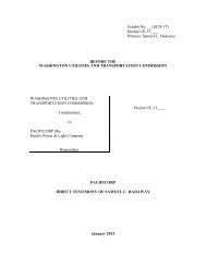
the easternmost states. This is illustrated by the Ground Flash Density Map shown in Figure<br />
1. This document will refer to Zones 1 <strong>and</strong> 2. Zone 1 is defined as an area with a ground<br />
flash density lower than .5 flashes/km2 /year. Zone 2 is an area with a ground flash density<br />
greater than .5 flashes/km2/year. Wyoming, Eastern Idaho, <strong>and</strong> Utah will all be considered<br />
Zone 2 for purposes of application of the practices described in this document.<br />
For system voltages of 345 kV <strong>and</strong> above, overvoltage protection is more often necessary to<br />
protect against switching surges, rather than lightning. Therefore, the st<strong>and</strong>ards for higher<br />
voltage systems are uniform across the company.<br />
8 Feb 10 1B.7 Page 1 of 10
Volume 1—General<br />
Part B—Operability <strong>and</strong> Reliability Guidelines<br />
Section 7—Lightning <strong>and</strong> <strong>Other</strong> <strong>Overvoltage</strong> <strong>Protection</strong><br />
Figure 1—U. S. Flash Density Map<br />
1B.7 Page 2 of 10<br />
8 Feb 10
Volume 1—General<br />
Part B—Operability <strong>and</strong> Reliability Guidelines<br />
Section 7—Lightning <strong>and</strong> <strong>Other</strong> <strong>Overvoltage</strong> <strong>Protection</strong><br />
5 Substation <strong>Overvoltage</strong> <strong>Protection</strong><br />
Shield wires <strong>and</strong> lightning arresters are the primary means of overvoltage protection for<br />
substations <strong>and</strong> transmission lines. The practices in this document establish additional<br />
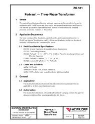
protection measures beyond those of past practices. Figure 2 illustrates the most significant<br />
changes to substations with high−side voltages of 138 kV <strong>and</strong> below.<br />
Figure 2—Distribution Substation <strong>Overvoltage</strong> <strong>Protection</strong> (Zone 2)<br />
5.1 Substations with High-Side Voltages of 138 kV <strong>and</strong> Below<br />
5.1.1 Substation Shielding<br />
Substations located in Zone 2 shall be shielded with overhead shield wires or<br />
lightning masts. The fixed angle method, per IEEE 998, shall be used with a<br />
45-degree angle for heights up to 60 feet, <strong>and</strong> a 30-degree angle for heights above<br />
60 feet.<br />
Substations located in Zone 1 shall not be shielded unless the incoming<br />
transmission lines are shielded over the entire length.<br />
5.1.2 Transformer <strong>Protection</strong><br />
All power transformers shall be protected with high− <strong>and</strong> low−side lightning<br />
arresters. Refer to Table 1, <strong>and</strong> PacifiCorp Material Specification ZS 001 for<br />
arrester sizes.<br />
8 Feb 10 1B.7 Page 3 of 10
Volume 1—General<br />
Part B—Operability <strong>and</strong> Reliability Guidelines<br />
Section 7—Lightning <strong>and</strong> <strong>Other</strong> <strong>Overvoltage</strong> <strong>Protection</strong><br />
Table 1—Transformer Surge Arrester Rating Guide<br />
Transformer<br />
Nameplate<br />
Voltage<br />
Transformer<br />
Winding BIL<br />
Arrester Duty Cycle Rating Stock Item # MCOV<br />
Grounded<br />
Systems<br />
Ungrounded<br />
Systems<br />
Grounded<br />
Systems<br />
Ungrounded<br />
Systems<br />
525 kV 1425 kV 420 kV n/a (TBD) n/a 335 kV<br />
345 kV 1050 kV 264 kV n/a 7882325 n/a 212 kV<br />
230 kV 750 kV 180 kV n/a 9600416 n/a 144 kV<br />
161 kV 650 kV 132 kV n/a 7887345 n/a 106 kV<br />
138 kV 550 kV 120 kV n/a 8100175 n/a 98 kV<br />
115 kV 450 kV 96 kV 9600160 76 kV<br />
120 kV 7887373 98 kV<br />
69 kV 350 kV 60 kV 9602189 48 kV<br />
72 kV 1003204 57 kV<br />
46 kV 250 kV 39 kV 1004075 31.5 kV<br />
48 kV 7887346 39 kV<br />
34.5 kV 200 kV 30 kV 7887347 24.4 kV<br />
36 kV 7887348 29 kV<br />
25.0 kV 150 kV 21 kV 7887095 17 kV<br />
27 kV 7887349 22 kV<br />
20.8 kV 150 kV 21 kV 7887095 17 kV<br />
27 kV 7887349 22 kV<br />
13.8 kV 110 kV 12 kV 7887171 10.2 kV<br />
15 kV 1008491 12.7 kV<br />
13.2 kV 110 kV 12 kV 7887171 10.2 kV<br />
15 kV 1008491 12.7 kV<br />
13.09 kV 110 kV 12 kV 7887171 10.2 kV<br />
15 kV 1008491 12.7 kV<br />
12.5 kV 110 kV 12 kV 7887171 10.2 kV<br />
15 kV 1008491 12.7 kV<br />
5.1.3 Breaker <strong>Protection</strong>—69 kV to 138 kV<br />
In both Zones 1 <strong>and</strong> 2, the high-side breakers shall be protected by lightning<br />
arresters installed on the line side of the breakers (Refer to Table 2 for arrester<br />
sizes). In some cases, the breaker may be protected by the arrester on the<br />
transformer if they are very close (30 ft. for 138 kV) to one another. Check with<br />
Substation St<strong>and</strong>ards Engineering for any question regarding the need for<br />
arresters at the breaker.<br />
1B.7 Page 4 of 10<br />
8 Feb 10
Volume 1—General<br />
Part B—Operability <strong>and</strong> Reliability Guidelines<br />
Section 7—Lightning <strong>and</strong> <strong>Other</strong> <strong>Overvoltage</strong> <strong>Protection</strong><br />
Table 2—Line Entrance Surge Arrester Rating Guide<br />
Nominal<br />
System<br />
Voltage<br />
Breaker/<br />
Trans. Line<br />
BIL<br />
Arrester Duty Cycle Rating<br />
Grounded<br />
Systems<br />
Ungrounded<br />
Systems<br />
Stock Item Number<br />
Grounded<br />
Systems<br />
Ungrounded<br />
Systems<br />
MCOV<br />
Arrester Minimum<br />
Energy Capability<br />
Based on One Shot<br />
525 kV 1800/1800 kV 420 kV n/a (TBD) n/a 335 kV 13KJ/KV of MCOV<br />
345 KV 1300/1300 KV 276 kV n/a (TBD) n/a 220 kV 9KJ/KV of MCOV<br />
230 kV 900/900 kV 180 kV n/a 9600416 n/a 144 kV 5kJ/KV of MCOV<br />
161 kV 750/750 kV 132 kV n/a 7887345 n/a 106 kV 5KJ/KV of MCOV<br />
138 kV 650/650 kV 120 kV n/a 8100175 n/a 98 kV 5KJ/KV of MCOV<br />
115 kV 650/550 kV 96 kV 9600160 76 kV 5KJ/KV of MCOV<br />
120 kV 7887373 98 kV 5KJ/KV of MCOV<br />
69 kV 350/350 kV 60 kV 9602189 48 kV 5KJ/KV of MCOV<br />
72 kV 1003204 57 kV 5KJ/KV of MCOV<br />
46 kV 350/250 kV 39 kV 1004075 31.5 kV 5KJ/KV of MCOV<br />
48 kV 7887346 39 kV 5KJ/KV of MCOV<br />
Notes<br />
The length of 525 <strong>and</strong> 345 kV transmission lines was assumed to be 300 miles or less.<br />
The length of 230 <strong>and</strong> 169 kV transmission lines was assumed to be 200 miles or less.<br />
The length of 138 to 46 kV transmission lines was assumed to be 150 miles or less.<br />
5.1.4 High-Side Bus <strong>Protection</strong><br />
If there are no high−side breakers, spill gaps shall be installed at the transmission<br />
line terminals in both Zones 1 <strong>and</strong> 2. Table 3 lists the requirements for spill gaps.<br />
Maximum System Voltage<br />
Phase-to-phase<br />
(kV)<br />
Table 3—Spill Gap Settings<br />
Basic Impulse Insulation Level<br />
(BIL)<br />
(kV)<br />
Spill gap spacing S at sea level<br />
(inches)<br />
48 250 7.5<br />
72.5 350 11<br />
121 550 19<br />
145 650 23<br />
169 750 27<br />
242 900 40<br />
8 Feb 10 1B.7 Page 5 of 10
Volume 1—General<br />
Part B—Operability <strong>and</strong> Reliability Guidelines<br />
Section 7—Lightning <strong>and</strong> <strong>Other</strong> <strong>Overvoltage</strong> <strong>Protection</strong><br />
Table 4—Altitude Correction Factors<br />
Altitude (ft) 500 1000 1500 2000 2500 3000 3500<br />
Correction Factor δ (Note 3) 0.982 0.965 0.948 0.931 0.915 0.899 0.883<br />
Altitude (ft) 4000 4500 5000 5500 6000 6500 7000<br />
Correction Factor δ (Note 3) 0.868 0.852 0.837 0.823 0.808 0.794 0.780<br />
Note 1. The spill gaps are set to withst<strong>and</strong> a 2.5 pu switching surge at sea level, using the formula:<br />
(IEEE Std.1313.2−1999 Eq. 27), where k g = the gap factor given in Table 10.<br />
For rod−to−rod (vertical) gaps, the value = 1.30, <strong>and</strong> CFO is the switching surge.<br />
Note 2. Switching surge line-to-ground at sea level is calculated using the formula:<br />
where E max = the system’s maximum voltage <strong>and</strong> pu = the per unit switching surge factor.<br />
Note 3. To find spill gap setting at different altitude, use the values listed in Table 4, which were<br />
developed with the formula:<br />
where A = the altitude in kilometers. The setting at sea level should be divided by the<br />
altitude correction factor to get the gap setting at the desired altitude.<br />
Note 4. The settings were checked to be below the withst<strong>and</strong> capabilities of the station post<br />
insulator,<br />
determined with the formula:<br />
This formula is from IEEE 1313.2−1999, Eq. 23, where H i is the insulator height in<br />
meters, <strong>and</strong> BSL is the basic switching level.<br />
5.1.5 Feeder Getaway <strong>Protection</strong><br />
Underground Getaways − Riser pole arresters shall be installed on both ends of<br />
underground getaways in open−bus substations. For underground getaways<br />
1B.7 Page 6 of 10<br />
8 Feb 10
Volume 1—General<br />
Part B—Operability <strong>and</strong> Reliability Guidelines<br />
Section 7—Lightning <strong>and</strong> <strong>Other</strong> <strong>Overvoltage</strong> <strong>Protection</strong><br />
exiting from metalclad switchgear, an arrester shall only be installed at the riser<br />
pole on the load side of the getaway.<br />
Overhead Getaways − Distribution class arresters shall be installed as close as<br />
possible to the getaway conductors where they attach to the substation bus<br />
structure.<br />
5.2 Substations with Voltages of 161 kV <strong>and</strong> Above<br />
5.2.1 Substation Shielding<br />
All transmission substations shall be shielded. The fixed angle method, per IEEE<br />
998, shall be used with a 45-degree angle for heights up to 60 feet, <strong>and</strong> 30-degree<br />
angle for heights above 60 feet.<br />
5.2.2 Transformer <strong>Protection</strong><br />
All power transformers shall be protected with high− <strong>and</strong> low−side lightning<br />
arresters. Refer to Table 1, <strong>and</strong> PacifiCorp Material Specification ZS 001 for<br />
arrester sizes.<br />
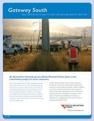
5.2.3 Breaker <strong>Protection</strong><br />
All breakers, at voltages of 69 kV <strong>and</strong> above, shall be protected by line entrance<br />
arresters. The example in Figure 3 illustrates that 138 <strong>and</strong> 230 kV line terminals<br />
with breakers, previously protected by spill gaps, will now have arresters<br />
installed. Refer to Table 2 for arrester sizes.<br />
5.2.4 High−Side Bus <strong>Protection</strong><br />
If there are no high−side breakers, spill gaps shall be installed at the transmission<br />
line terminals. Table 3 lists the requirements for spill gaps.<br />
8 Feb 10 1B.7 Page 7 of 10
Volume 1—General<br />
Part B—Operability <strong>and</strong> Reliability Guidelines<br />
Section 7—Lightning <strong>and</strong> <strong>Other</strong> <strong>Overvoltage</strong> <strong>Protection</strong><br />
Figure 3—Typical Transmission Substation <strong>Overvoltage</strong> <strong>Protection</strong><br />
6 Transmission Line <strong>Overvoltage</strong> <strong>Protection</strong><br />
6.1 Shield Wire<br />
Refer to PacifiCorp Transmission Construction St<strong>and</strong>ard TD 201, Shield<br />
Wire—Lightning <strong>Protection</strong> Locations<br />
1B.7 Page 8 of 10<br />
8 Feb 10
Volume 1—General<br />
Part B—Operability <strong>and</strong> Reliability Guidelines<br />
Section 7—Lightning <strong>and</strong> <strong>Other</strong> <strong>Overvoltage</strong> <strong>Protection</strong><br />
7 Issuing Department, Approvals <strong>and</strong> Authorization<br />
The Asset Management Department of PacifiCorp is responsible for issuing this document.<br />
Comments <strong>and</strong> suggestions are welcome. Additional copies may be obtained from:<br />
Asset Management Documentation, Lloyd Center Tower<br />
825 NE Multnomah St., Suite 1600, Portl<strong>and</strong>, Oregon 97232<br />
Telephone: (503) 813−5293 Fax: (503) 813−6804<br />
Signed approval records are on file. Publication <strong>and</strong> use of this document in support of<br />
PacifiCorp projects is authorized by the employees listed below.<br />
Approved:<br />
Iuda Morar, Engineer<br />
St<strong>and</strong>ards Engineering <strong>and</strong> Technology Development<br />
Approved:<br />
Greg Lyons, Manager<br />
St<strong>and</strong>ards Engineering <strong>and</strong> Technology Development<br />
8 Feb 10 1B.7 Page 9 of 10
Volume 1—General<br />
Part B—Operability <strong>and</strong> Reliability Guidelines<br />
Section 7—Lightning <strong>and</strong> <strong>Other</strong> <strong>Overvoltage</strong> <strong>Protection</strong><br />
This page is left blank intentionally.<br />
1B.7 Page 10 of 10<br />
8 Feb 10