CP62(2x5/8 wave)
CP62(2x5/8 wave)
CP62(2x5/8 wave)

You also want an ePaper? Increase the reach of your titles
YUMPU automatically turns print PDFs into web optimized ePapers that Google loves.
6mVertical Antenna<br />
<strong>CP62</strong>(<strong>2x5</strong>/8 <strong>wave</strong>)<br />
Operation Instructions<br />
To use this antenna properly, read<br />
this instruction thoroughly before<br />
using it, Keep this manual carefully<br />
at hand for later use.<br />
Description<br />
1/4 <strong>wave</strong> ground plane antenna<br />
permits longer ground <strong>wave</strong><br />
propagation range and<br />
advantageous for ionospheric<br />
reflection DX communication.<br />
Compact, light weighted and very<br />
easy to assemble.<br />
It is completely self-supported and<br />
does not need any guy wires.<br />
It is rigid and rugged enough to<br />
withstand the wind pressure over<br />
79MPH.<br />
Mast brackets area adjustable to<br />
accept 1 1/5” to 2 1/3” diameter<br />
mast.<br />
Feed point section is kept<br />
waterproof by covering it with<br />
support pipe.<br />
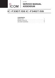
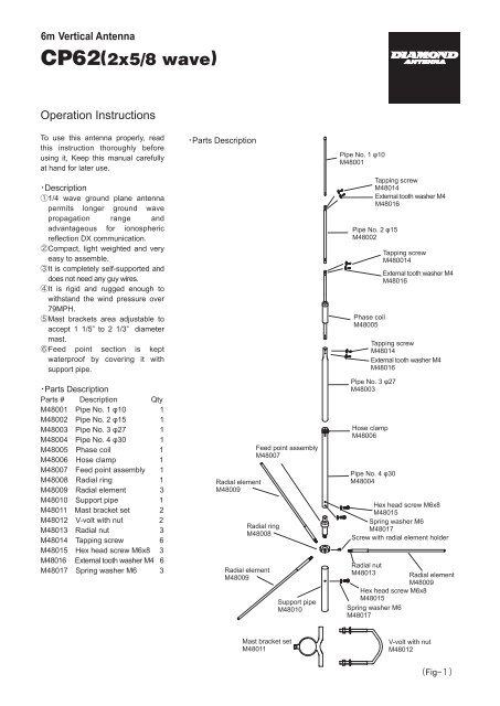
Parts Description<br />
Parts #DescriptionQty<br />
M48001Pipe No. 1 φ101<br />
M48002Pipe No. 2 φ151<br />
M48003Pipe No. 3 φ271<br />
M48004Pipe No. 4 φ301<br />
M48005Phase coil 1<br />
M48006Hose clamp 1<br />
M48007Feed point assembly1<br />
M48008Radial ring 1<br />
M48009Radial element3<br />
M48010Support pipe 1<br />
M48011Mast bracket set2<br />
M48012V-volt with nut 2<br />
M48013Radial nut3<br />
M48014Tapping screw 6<br />
M48015Hex head screw M6x83<br />
M48016External tooth washer M46<br />
M48017Spring washer M63<br />
Parts Description<br />
Radial element<br />
M48009<br />
Radial ring<br />
M48008<br />
Radial element<br />
M48009<br />
Feed point assembly<br />
M48007<br />
Support pipe<br />
M48010<br />
Pipe No. 1 φ10<br />
M48001<br />
Pipe No. 2 φ15<br />
M48002<br />
Phase coil<br />
M48005<br />
Pipe No. 3 φ27<br />
M48003<br />
Hose clamp<br />
M48006<br />
Tapping screw<br />
M48014<br />
External tooth washer M4<br />
M48016<br />
Pipe No. 4 φ30<br />
M48004<br />
Tapping screw<br />
M480014<br />
External tooth washer M4<br />
M48016<br />
Tapping screw<br />
M48014<br />
External tooth washer M4<br />
M48016<br />
Hex head screw M6x8<br />
M48015<br />
Spring washer M6<br />
M48017<br />
Screw with radial element holder<br />
Radial nut<br />
M48013<br />
Hex head screw M6x8<br />
M48015<br />
Spring washer M6<br />
M48017<br />
Radial element<br />
M48009<br />
Mast bracket set<br />
M48011<br />
V-volt with nut<br />
M48012<br />
Fig−
-Note-----------------------------------------<br />
<br />
Don’t install on a rainy or windy<br />
day since it is dangerous.<br />
Don’t attempt to install the<br />
antenna only by yourself. Installing<br />
the antenna alone on the roof may<br />
lead you dangerous accident.<br />
Always ask your friends for help<br />
installing the antenna.<br />
Don’t drop the antenna, tools and<br />
attachment when installing the<br />
antenna in the height. Install the<br />
antenna before assembling it on<br />
the ground.<br />
<br />
If the <strong>CP62</strong> is located on the roof<br />
of a house or top of a building,<br />
look around the roof to see if there<br />
are any obstacles such as an<br />
electronic wire or TV antenna. The<br />
<strong>CP62</strong> has to be located as far<br />
away as possible from those things<br />
to obtain its maximum performance.<br />
Installing the antenna too close to<br />
the building wall may cause bad<br />
effect for electrical characteristics<br />
of the antenna.<br />
Don’t install the antenna where is<br />
easily reachable by people.<br />
Install the antenna firmly not to fall<br />
down due to the strong wind. Even<br />
if falling down the antenna, locate<br />
the antenna at the safe place where<br />
people and building are not<br />
inflicted injures.<br />
<br />
Transmit after confirming if the<br />
antenna works normally by an<br />
SWR meter. If VSWR is less than<br />
1.5, it is no problem. If VSWR is<br />
higher, stop transmitting and check<br />
if the parts of the antenna and coaxial<br />
cable are connected. If there are<br />
tall buildings or obstacles or the<br />
distance between the antenna and<br />
the ground is short, VSWR may<br />
not be lowered.<br />
Diamond Antenna SWR/POWER<br />
meter is an insertion type being<br />
connected between a transmitter and<br />
an antenna. Transmitting power and<br />
SWR can be measured with very<br />
simple operations. In addition with<br />
those conventional measurement,<br />
PEP (peak envelope power) on<br />
SSB mode can be measured with<br />
a PEP monitor function. With our<br />
Diamond’s wideband and low<br />
insertion loss directional coupler<br />
those measurements can be<br />
performed with minimum effect in<br />
transmission line.<br />
<br />
Touching the antenna during<br />
transmission may cause to<br />
electrify. Pay attention not to touch<br />
the antenna especially for children<br />
if installing on a balcony railing.<br />
<br />
The thunder seems to rumble in<br />
the vicinity, don’t touch the<br />
antenna and coaxial.<br />
When you don’t use the radio,<br />
take off the cable from the radio.<br />
<br />
Keeping transmitting with high<br />
VSWR may cause the radio to be<br />
damaged.<br />
Stop transmitting immediately and<br />
check the following matters. If it<br />
doesn’t solve the problem, please<br />
ask the dealer or Diamond<br />
Antenna Corporation.<br />
[Condition: If the antenna doesn’t<br />
seem to receive well or<br />
propagate well]<br />
Check 1:Is the antenna too close to<br />
the building wall? If the<br />
obstacles are too close to<br />
antenna, VSWR is higher<br />
and the radiation pattern is<br />
disturbed. Please install the<br />
antenna from the building<br />
as far away as possible.<br />
Check 2:Did you assemble the antenna<br />
correctly? Please read the<br />
instruction again and<br />
reconfirm the assembly.<br />
Check 3:Is the coaxial cable something<br />
wrong? Please check if<br />
soldering the connector is<br />
okay and the wire breaks<br />
by the volt-ohm meter.<br />
Antenna location<br />
Resonate frequency of HF antenna<br />
can change based on location.<br />
Antenna should be mounted away<br />
from tree, building and other<br />
antennas.<br />
If the <strong>CP62</strong> is located on the roof<br />
of a house or top of a building,<br />
look around the roof to see if there<br />
are any obstacles such as TV<br />
antenna or water reservation tank.<br />
The <strong>CP62</strong> has to be located as far<br />
away as possible from those<br />
things to obtain its maximum<br />
performance.<br />
If the <strong>CP62</strong> is installed on a<br />
balcony railing, installing the<br />
antenna too close to the building<br />
wall may cause bad effect for<br />
electrical characteristics of the<br />
antenna. Locate at least 2m to 5m<br />
(7’ to 16’) away from the building<br />
wall depending on structure of the<br />
building.<br />
<br />
<br />
In case of using the metallic stay<br />
wire, set the wire on the lower mast<br />
bracket set and attach the<br />
insulators at within 1m from the<br />
mast bracket set in order to<br />
insulate.<br />
Radial nut<br />
Radial element<br />
Fig2<br />
Assembly Instruction<br />
Put radial nut into radial element<br />
and fasten it loosely.<br />
Connect pipe No.1, pipe No. 2,<br />
Phase coil, pipe No. 3, pipe No.4<br />
in the vertical element section and<br />
fastening them with tapping<br />
screws and external tooth<br />
washers by aligning holes in each<br />
joint section. Connect pipe No. 3<br />
and pipe No. 4 with hose clamp.<br />
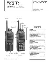
Adjust the insertion length of pipe<br />
No. 3 depending on the frequency.<br />
(Refer to the below chart)<br />
Insertion length of pipe/Resonate<br />
fequency<br />
<br />
<br />
<br />
<br />
<br />
<br />
<br />
<br />
<br />
Pipe No. 3<br />
Insertion length<br />
Pipe No. 4
Attach mast support pipe to mast<br />
with mast brackets. Mast support<br />
pipe’s tapping hole has to be<br />
placed above the brackets and it<br />
has to be pointed outside against<br />
the mast. Upper end of mast<br />
support pipe has to be placed more<br />
than 12cm(4.7”) above the top end<br />
of the mast.<br />
<br />
Applox. 12cm(4.7")<br />
<br />
Mast<br />
Coaxial cable<br />
Trapping hole<br />
this side<br />
Support pipe<br />
Turn each radial element into radial<br />
element holders. Then align water<br />
drain hole in each radial element<br />
trap coil assembly downward by<br />
turning backward and fasten each<br />
element with grip nut, Note that 6m<br />
radial element does not have trap<br />
coil assembly.<br />
Hex head screw<br />
Screw<br />
Hex head screw<br />
Pipe No. 4<br />
Feed point assembly<br />
Grip nut Radial element<br />
Radial element holder<br />
Mast support pipe<br />
Specifications<br />
Frequency range50-54MHz<br />
Gain5.5dBi<br />
Maximum power rating <br />
500W(SSB), 200(FM)<br />
VSWR Less than 1.5<br />
Impedance50Ω<br />
Length 6.8m (max)<br />
Weight Approx. 2.7kg<br />
Maximum wind resistance<br />
79MPH (35m/sec)<br />
Mast diameter accepted<br />
1 1/5” – 2 1/3”(30-62φ)<br />
Radial element length1.5m<br />
Type<strong>2x5</strong>/8<strong>wave</strong><br />
ConnectorM-J<br />
V-bolt<br />
Mast<br />
Mast brackets<br />
Support<br />
pipe<br />
Spring washer<br />
Nut<br />
(Fig-3<br />
Place two radial element holders<br />
from upper end of the support pipe<br />
and fasten temporary with screwdriver.<br />
Do not fasten too tightly at<br />
this stage, otherwise feedpoint<br />
assemblies might not be put into<br />
the support mast later.<br />
Connect a coaxial cable to<br />
feedpoint assemble through the<br />
support pipe. Then align the hole in<br />
the lower part of feedpoint assembly<br />
with the hole in the support pipe<br />
and secure them with hex head<br />
screw and spring washer. (note)<br />
Please do the waterproof processing<br />
to the connector section.<br />
Place vertical element on feedpoint<br />
assembly and fix with two hex<br />
head screws and spring washers.<br />
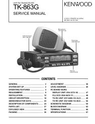
Adjustment<br />
<br />
Practice the following adjustment<br />
procedure at the place where the<br />
antenna is actually installed.<br />
Test transmission for the adjustment<br />
has to be performed for as short time<br />
as possible and with as low RF power<br />
as possible. Maximum RF power<br />
rating of continuous <strong>wave</strong> (CW) is<br />
about 1/3 of it in SSB mode.<br />
Prepare suitable VSWR meter for<br />
operation frequency and output RF<br />
power. Then connect it as shown in<br />
below.<br />
<br />
<br />
<br />
<br />
<br />
Tranceiver<br />
VSWR<br />
meter<br />
<strong>CP62</strong><br />
(Fig-5<br />
When assembling, the insertion<br />
length of pipe No. 3 is adjusted but<br />
confirm it again. Adjust the insertion<br />
length of pipe No. 3 if the<br />
frequency is not adjusted.<br />
V.SWR<br />
(Fig-4<br />
Though these products purchased<br />
are manufactured under strict quality<br />
control, if damage is caused by transporting,<br />
ask your dealer promptly.<br />
Design and specifications of these<br />
products will be changed for future<br />
improvement without advance notice.<br />
<br />
f0