LIM-2 Logic Inspection Module
LIM-2 Logic Inspection Module
LIM-2 Logic Inspection Module

Create successful ePaper yourself
Turn your PDF publications into a flip-book with our unique Google optimized e-Paper software.
A Flow Control Application<br />
Using the <strong>LIM</strong>-2 <strong>Logic</strong> <strong>Inspection</strong> <strong>Module</strong><br />
The Application<br />
Parts are processed through a heat<br />
tunnel on a continuous motion<br />
conveyor. Opposed mode photoelectric<br />
sensors are placed at the<br />
entrance and exit of the heat tunnel to<br />
monitor part flow. An <strong>LIM</strong>-2 and an<br />
LSR-64 shift register module process<br />
the information from the sensors<br />
and activate an alarm if a part does<br />
not emerge from the tunnel when it<br />
should. The length of the parts and<br />
the spacing between adjacent parts<br />
may be random.<br />
Application Concept<br />
The System<br />
A narrow beam is established near<br />
both the entrance and the exit of the<br />
heat tunnel using SM30 Series sensors<br />
with rectangular aperture assemblies<br />
on the emitter and the receiver. The<br />
Bi-Modal receiver outputs are wired<br />
for dark operate and sinking (NPN)<br />
operation.<br />
When the beam of the entrance sensors<br />
is blocked, data is input to the LSR-64<br />
shift register. The length of the part<br />
corresponds to the number of clock<br />
pulses entered during the time that<br />
the entrance beam is blocked. Clock<br />
pulses are generated using an ECONO-<br />
BEAM SE61E/SE61R combination as<br />
a slot sensor to count pulses produced<br />
by a timing sprocket attached to one<br />
of the conveyor drive shafts.<br />
The LSR-64 is programmed to output<br />
when the part is clocked to the exit of<br />
the tunnel. This information becomes<br />
the gate input for the <strong>LIM</strong>-2. The exit<br />
sensors supply a DATA signal to the<br />
<strong>LIM</strong>-2 when the beam is blocked by<br />
an exiting part. The exit sensors must<br />
“see” the leading edge of an exiting part<br />
at any time during the gate period in<br />
order to prevent an alarm.<br />
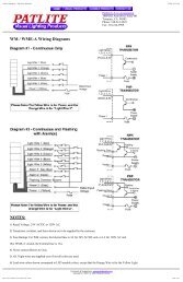
Hookup Diagram<br />
Timing Diagram (assumes shift length of 5)<br />
4