LIM-2 Logic Inspection Module
LIM-2 Logic Inspection Module
LIM-2 Logic Inspection Module

You also want an ePaper? Increase the reach of your titles
YUMPU automatically turns print PDFs into web optimized ePapers that Google loves.
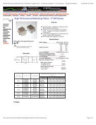
Plug <strong>Logic</strong><br />
<strong>LIM</strong>-2<br />
<strong>Logic</strong> <strong>Inspection</strong> <strong>Module</strong><br />
• Coordinates a gating signal with data from an inspection sensor<br />
for accept/reject and other similar control applications<br />
•<br />
Inputs may be derived from contact closures or any dc sensor<br />
(or sensing system) with NPN (sinking) output<br />
•<br />
Programmable to replace many dedicated-function Banner logic<br />
modules<br />
OS-8 socket sold separately<br />
General<br />
The model <strong>LIM</strong>-2 logic inspection module may be used in nearly any high-speed<br />
inspection application where it is necessary to know whether an event did or did not<br />
occur within a specified time period, or "gate window". Typical <strong>LIM</strong>-2 applications<br />
include:<br />
Missing part detection No bottle/no fill control<br />
Die protection<br />
Full case inspection<br />
Code reading ("train logic") Rotary index table inspection<br />
Inspecting for foreign objects Low fill level monitoring<br />
Three typical <strong>LIM</strong>-2 applications are discussed on pages 3 through 6.<br />
The <strong>LIM</strong>-2 operates on signals derived from contact closures or dc-type photoelectric<br />
or proximity sensors having an NPN sinking output transistor. Easily-accessible internal<br />
logic (DIP) switches enable customer-programming of eight different inspection<br />
variables including input response times, signal polarities, and output characteristics<br />
(see Table 1, page 2). This high level of versatility means that the <strong>LIM</strong>-2 can often<br />
replace other types of logic modules (e.g. Banner B4-2-1500B, BIC-2, DP1A, and<br />
WARNING <strong>Module</strong> model <strong>LIM</strong>-2, described in this data sheet,<br />
does NOT include the self-checking redundant circuitry necessary to allow<br />
its use in personnel safety applications. A sensor or module failure<br />
or malfunction can result in either an energized or a de-energized output<br />
condition.<br />
Never use these products for personnel protection. Their use as safety<br />
devices may create an unsafe condition which could lead to serious injury or death.<br />
Only MACHINE-GUARD and PERIMETER-GUARD Systems, and other systems so designated,<br />
are designed to meet OSHA and ANSI machine safety standards for point-of-operation<br />
guarding devices. No other Banner sensors or controls are designed to meet these standards,<br />
and they must NOT be used as sensing devices for personnel protection.<br />
TL2A) while providing additional capabilities<br />
not found in those original modules (Table 2,<br />
page 6).<br />
The <strong>LIM</strong>-2 module measures 3.0 x 3.0 x 1.5<br />
inches, and plugs into a standard octal socket<br />
such as the Banner OS-8 (sold separately). Up<br />
to 256 field-programmable operating modes are<br />
possible.<br />
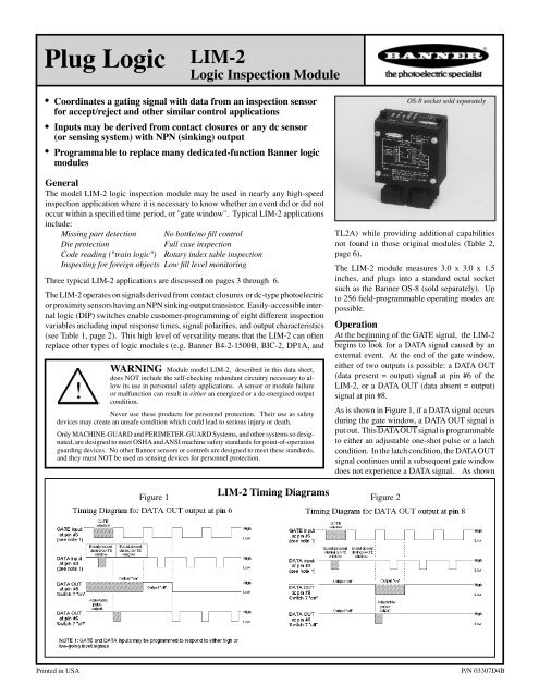
Operation<br />
At the beginning of the GATE signal, the <strong>LIM</strong>-2<br />
begins to look for a DATA signal caused by an<br />
external event. At the end of the gate window,<br />
either of two outputs is possible: a DATA OUT<br />
(data present = output) signal at pin #6 of the<br />
<strong>LIM</strong>-2, or a DATA OUT (data absent = output)<br />
signal at pin #8.<br />
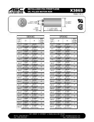
As is shown in Figure 1, if a DATA signal occurs<br />
during the gate window, a DATA OUT signal is<br />
put out. This DATA OUT signal is programmable<br />
to either an adjustable one-shot pulse or a latch<br />
condition. In the latch condition, the DATA OUT<br />
signal continues until a subsequent gate window<br />
does not experience a DATA signal. As shown<br />
Figure 1<br />
<strong>LIM</strong>-2 Timing Diagrams<br />
Figure 2<br />
Printed in USA<br />
P/N 03307D4B
Switch<br />
Table 1. <strong>LIM</strong>-2 Programming Options<br />
Number "ON" Position "OFF" Position<br />
1 Gate input has 10 millisecond response time<br />
Gate input has 1 millisecond response time<br />
2<br />
3<br />
4<br />
Data input has 10 millisecond response time<br />
GATE signal is entered when pin #5 is "low" (logic 0)<br />
DATA signal is entered when pin #3 is "low" (logic 0)<br />
Data input has 1 millisecond response time<br />
GATE signal is entered when pin #5 is "high" (logic 1)<br />
DATA signal is entered when pin #3 is "high" (logic 1)<br />
5<br />
6<br />
7<br />
8<br />
Gate window remains open for as long as the GATE<br />
signal is present<br />
Data may be entered at any time during the gate window,<br />
or it may be continuous<br />
Outputs latch in their last state until the end of the next<br />
gate window<br />
Output one-shot time is adjustable from .05 to 1 second<br />
Gate window occurs only at the leading edge of the gate<br />
input<br />
A data transition must occur while the gate window is<br />
open<br />
Appropriate output energizes for a one-shot pulse at the<br />
end of each gate window<br />
Output one-shot time is adjustable from .005 to .1 second<br />
Specifications, model <strong>LIM</strong>-2 <strong>Logic</strong> <strong>Inspection</strong> <strong>Module</strong><br />
Supply Voltage:<br />
10 to 30V dc at 25mA (exclusive of loads); may be supplied by MAXI-<br />
AMP model CP12C or CP12RC power supply module (see product<br />
catalog or data sheet P/N 03460 for more information).<br />
Outputs:<br />
Two NPN open-collector transistors (DATA OUT and DATA OUT);<br />
maximum current sink 150mA each.<br />
In the one-shot mode, the appropriate output pulses for an adjustable<br />
time (.005 to 1 second) at the end of each GATE signal.<br />
In the latched mode, the outputs are latched in the appropriate state (one<br />
or the other conducting) at the end of each GATE signal.<br />
Response Time:<br />
Selectable to 1 millisecond or 10 milliseconds.<br />
Indicators:<br />
Four LEDs indicate the presence of the following signals: GATE, DATA<br />
IN, DATA OUT, and DATA OUT.<br />
Input Requirements:<br />
For logic level signals, logic "low" must less than 2V dc, and logic<br />
"high" must be an open circuit or a voltage greater than 6V dc. Input<br />
device(s) must be capable of sinking 4ma.<br />
Construction:<br />
3.0 x 3.0 x 1.5 inch plug-in module with standard octal base. NEMA<br />
1 anodized aluminum enclosure.<br />
The octal base of the <strong>LIM</strong>-2 fits the Banner model OS-8 octal socket<br />
(order separately).<br />
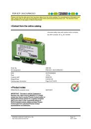
Dimensions, model <strong>LIM</strong>-2<br />
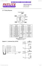
<strong>LIM</strong>-2 Basic Hookup<br />
LED indicators behind the transparent module top cover indicate<br />
the presence of GATE, DATA, DATA OUT, and DATA OUT.<br />
<strong>Logic</strong> programming (DIP) switches and the one-shot pulse duration<br />
adjustment potentiometer are also located behind the easilyremoveable<br />
top cover.<br />
2
A Die Protection Application<br />
Using the <strong>LIM</strong>-2 <strong>Logic</strong> <strong>Inspection</strong> <strong>Module</strong><br />
The Application<br />
One part is ejected during each cycle of a blanking press. A photoelectric light screen is used to detect the blanked parts as they are ejected<br />
from the press. The press is immediately stopped if an ejected part is not sensed before an upstroke is completed. This system prevents serious<br />
damage to the blanking die and/or press which can result when a blanked part becomes stuck in the press.<br />
The System<br />
An ejected part is propelled through a defined area. Its motion is random as it tumbles out of the throat of the press and into an accumulator bin.<br />
Parts which present a profile of 0.2 inches or more in cross section may be reliably sensed passing anywhere through the 3.5 inch high window<br />
of an LS10 light screen sensor pair. The LS10 sensors may be separated by up to 48 inches (see data sheet P/N 03557).<br />
<strong>Logic</strong> for the die protection is supplied by an <strong>LIM</strong>-2 module. The DATA signal is supplied by the LS10R receiver, which outputs a pulse to the<br />
<strong>LIM</strong>-2 each time a part passes through the light screen. The current sinking (NPN) output of the light screen receiver is used.<br />
The GATE signal is supplied by a metal proximity sensor which outputs a short signal near the end of each press upstroke. The GATE signal is<br />
generated by a metal cam that is attached to the flywheel shaft which moves past the sensor as the die opens. A normally open current sinking<br />
(NPN) output of the proximity sensor is connected to the gate input of the <strong>LIM</strong>-2.<br />
The entire system is powered by a CP12RC dc supply module. The control signal from the <strong>LIM</strong>-2 is routed back to the CP12RC to switch its<br />
built-in relay which, in turn, interfaces directly to the start/stop circuit of the blanking press.<br />
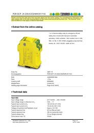
Theory of Operation<br />
The <strong>LIM</strong>-2 is programmed so that the gate window is the entire time<br />
period between consecutive gate sensor input signals (i.e. when the gate<br />
input is "high", switch #3 "off"). If an ejected part is sensed by the light<br />
screen at any time during the gate window, the press continues to cycle<br />
(see timing diagram, below). If no part is sensed during a gate window,<br />
the <strong>LIM</strong>-2 signals the machine control to shut down immediately at the<br />
end of that gate window.<br />
The data input is programmed (by switch #5) for ac-coupled response.<br />
This means that the <strong>LIM</strong>-2 must recognize a transition at the data input<br />
during the gate window. A transition occurs at the data input each<br />
time that a blanked part passes through the light screen. If the light<br />
screen becomes continuously interrupted by dirt, sensor misalignment,<br />
a stuck part, etc., the <strong>LIM</strong>-2 will sense this as a fault condition and<br />
stop the press.<br />
Timing Diagram<br />
Application Concept<br />
Larger or Smaller Parts<br />
The characteristics of the ejected parts determine selection of the most<br />
reliable and cost-effective light screen. Parts with a minimum profile of<br />
less than 0.2 inches may be detected by using model OSBFAC, together<br />
with rectangular opposed<br />
individual fiber optic assemblies<br />
(see product data<br />
sheet P/N 03553). Parts<br />
with a minimum profile of<br />
0.45 inch and greater, and<br />
which tumble through an<br />
area larger than 3.5 inches<br />
by 4 feet, may be sensed<br />
using a Banner BEAM-AR-<br />
RAY sensor pair (see data<br />
sheet P/N 03526).<br />
Hookup Diagram<br />
3
A Flow Control Application<br />
Using the <strong>LIM</strong>-2 <strong>Logic</strong> <strong>Inspection</strong> <strong>Module</strong><br />
The Application<br />
Parts are processed through a heat<br />
tunnel on a continuous motion<br />
conveyor. Opposed mode photoelectric<br />
sensors are placed at the<br />
entrance and exit of the heat tunnel to<br />
monitor part flow. An <strong>LIM</strong>-2 and an<br />
LSR-64 shift register module process<br />
the information from the sensors<br />
and activate an alarm if a part does<br />
not emerge from the tunnel when it<br />
should. The length of the parts and<br />
the spacing between adjacent parts<br />
may be random.<br />
Application Concept<br />
The System<br />
A narrow beam is established near<br />
both the entrance and the exit of the<br />
heat tunnel using SM30 Series sensors<br />
with rectangular aperture assemblies<br />
on the emitter and the receiver. The<br />
Bi-Modal receiver outputs are wired<br />
for dark operate and sinking (NPN)<br />
operation.<br />
When the beam of the entrance sensors<br />
is blocked, data is input to the LSR-64<br />
shift register. The length of the part<br />
corresponds to the number of clock<br />
pulses entered during the time that<br />
the entrance beam is blocked. Clock<br />
pulses are generated using an ECONO-<br />
BEAM SE61E/SE61R combination as<br />
a slot sensor to count pulses produced<br />
by a timing sprocket attached to one<br />
of the conveyor drive shafts.<br />
The LSR-64 is programmed to output<br />
when the part is clocked to the exit of<br />
the tunnel. This information becomes<br />
the gate input for the <strong>LIM</strong>-2. The exit<br />
sensors supply a DATA signal to the<br />
<strong>LIM</strong>-2 when the beam is blocked by<br />
an exiting part. The exit sensors must<br />
“see” the leading edge of an exiting part<br />
at any time during the gate period in<br />
order to prevent an alarm.<br />
Hookup Diagram<br />
Timing Diagram (assumes shift length of 5)<br />
4
An <strong>Inspection</strong>/rejection Application<br />
Using the <strong>LIM</strong>-2 <strong>Logic</strong> <strong>Inspection</strong> <strong>Module</strong><br />
The Application<br />
Opposed mode photoelectric sensors are used in this application to inspect spray cans for the presence or absence of a cap. The cans are also<br />
checked for caps that are not completely seated on the can. The caps are in various colors of opaque vinyl plastic. This inspection is coordinated<br />
by a model <strong>LIM</strong>-2.<br />
The System<br />
The GATE signal for the <strong>LIM</strong>-2 is generated by a pair of MINI-BEAM sensors. The gate beam is positioned so that it is interrupted by the main<br />
body of each can. The time that the gate beam is interrupted by the can corresponds to the duration of the gate window.<br />
<strong>Inspection</strong> is accomplished using two opposed beams, one to check for a missing cap and the other to check for a high (or crooked) cap. The<br />
beam for missing-cap detection is located comfortably beneath the top surface of the cap. The beam for high-cap detection is positioned just<br />
above the highest point of the cap, so that the beam is interrupted only by a cap that is not fully seated. Either of these two MINI-BEAM sensor<br />
pairs supplies data to the <strong>LIM</strong>-2.<br />
Reject cans are ejected by a solenoid at a reject station that is<br />
downstream from the inspection point. A model LSR-64 shift<br />
register module is used to track reject cans between the two<br />
locations. The CLOCK input signal for the shift register is<br />
generated using the ECONO-BEAM SE61E and SE61R which<br />
are configured as a slot sensor to count pulses produced by a<br />
timing sprocket attached to one of the conveyor drive shafts.<br />
A model BTR-1A is used to interface the shift register output<br />
to an ac reject solenoid. The BTR-1A is an infinite-life (solidstate)<br />
relay. Its use also eliminates the possibility of generating<br />
EMI and/or RFI from contact arcing.<br />
The hookup diagram for this system is shown on page 6.<br />
Timing Diagram<br />
5
Hookup, <strong>Inspection</strong>/rejection Application (continued from page 5)<br />
Switch settings (beneath module cover)<br />
Model Description Notes<br />
1 2 3 4 5 6 7 8<br />
B4-2-1500B<br />
One-shot<br />
inspection/rejection<br />
Table 2. Using the <strong>LIM</strong>-2 to Replace other Banner <strong>Module</strong>s<br />
OFF<br />
OFF<br />
ON<br />
ON<br />
OFF<br />
ON<br />
OFF<br />
ON<br />
Product sensor (interrogate) input at pin #5;<br />
<strong>Inspection</strong> sensor (data) input at pin #3;<br />
Output (pulse) at pin #8<br />
BIC-2<br />
"Flip-flop"<br />
(toggle)<br />
OFF<br />
OFF<br />
ON<br />
ON<br />
OFF<br />
ON<br />
ON<br />
OFF<br />
Jumper pin #8 to pin #3;<br />
Input at pin #5;<br />
Output at pin #6<br />
DP-1A<br />
Interrogation module;<br />
Die protection & other<br />
inspection sequences<br />
ON<br />
OFF<br />
OFF<br />
ON<br />
ON<br />
OFF<br />
ON<br />
OFF<br />
Cycle input (set) at pin #5;<br />
Part detection (reset) at pin #3;<br />
Output (latch) at pin #6<br />
TL2A<br />
Train logic module<br />
for code reading or<br />
"no can/no fill"<br />
OFF<br />
OFF<br />
ON<br />
ON<br />
OFF<br />
ON<br />
ON<br />
OFF<br />
Strobe input at pin #5;<br />
Data input at pin #3;<br />
Output (latch) at pin #6<br />
WARRANTY: Banner Engineering Corporation warrants its products to be free from defects for one year. Banner Engineering Corporation will<br />
repair or replace, without charge, any product of its manufacture found to be defective at the time it is returned to the factory during the warranty<br />
period. This warranty does not cover damage or liability for the improper application of Banner products. This warranty is in lieu of any other<br />
warranty either expressed or implied.<br />
Banner Enginnering Corp. 9714 10th Avenue No. Minneapolis, MN 55441 Telephone: (763) 544-3164 FAX (applications): (763) 544-3573