CISCA Prepares New Recommendations for Seismic Restraint - AWCI
CISCA Prepares New Recommendations for Seismic Restraint - AWCI
CISCA Prepares New Recommendations for Seismic Restraint - AWCI

Create successful ePaper yourself
Turn your PDF publications into a flip-book with our unique Google optimized e-Paper software.
<strong>CISCA</strong> <strong>Prepares</strong> <strong>New</strong> <strong>Recommendations</strong> <strong>for</strong><br />
<strong>Seismic</strong> <strong>Restraint</strong><br />
By Lee Cumming, Chair, <strong>CISCA</strong> <strong>Seismic</strong> Steering Committee<br />
Kelly Merz, ANCO Engineering, Inc.<br />
Carl A. Wangman, <strong>CISCA</strong> Executive Vice President<br />
and Judith Iacuzzi, <strong>CISCA</strong> Marketing/Communications Manager<br />
With the support of the National<br />
Science Foundation, the Ceilings and<br />
Interior Systems Construction Association<br />
(<strong>CISCA</strong>) <strong>for</strong> the past seven<br />
years has been conducting tests to<br />
determine whether the current Uni<strong>for</strong>m<br />
Building Code requirements <strong>for</strong><br />
suspended T-Bar ceiling seismic restraint<br />
is effective. The <strong>CISCA</strong> <strong>Seismic</strong><br />
Committee has recommended<br />
changes to the Uni<strong>for</strong>m Building Code,<br />
particularly affecting Zones 0, 1 and<br />
2.<br />
<strong>CISCA</strong> originally researched and<br />
drafted the first Standard <strong>for</strong> life safety<br />
in seismic areas in 1972. This was<br />
incorporated in the UBC in 1978.<br />
More recently, <strong>CISCA</strong> officials, working<br />
with engineers at ANCO Engineering,<br />
Inc., in Culver City, Cali<strong>for</strong>nia,<br />
decided to review the original<br />
standards, testing them <strong>for</strong> effectiveness.<br />
The result of this recent research<br />
is that <strong>CISCA</strong> now recommends clarification<br />
of and changes in the UBC<br />
<strong>for</strong> Zones 0-2. An article describing<br />
<strong>CISCA</strong>’s new recommendations <strong>for</strong><br />
Zones O-2 appears in the November<br />
issue of Interior Construction magazine.<br />
One of the issues identified by the<br />
<strong>CISCA</strong> <strong>Seismic</strong> Committee is the need<br />
<strong>for</strong> industry education on current UBC<br />
Standards <strong>for</strong> seismic restraint of<br />
ceilings. The following comments<br />
review recommendations in the current<br />
Standard, which does not distinguish<br />
between zones. The comments<br />
are intended to clarify currently recommended<br />
procedures <strong>for</strong> Zones 3<br />
and 4; however, like Zones 0-2, <strong>CISCA</strong><br />
leadership and the <strong>Seismic</strong> Committee<br />
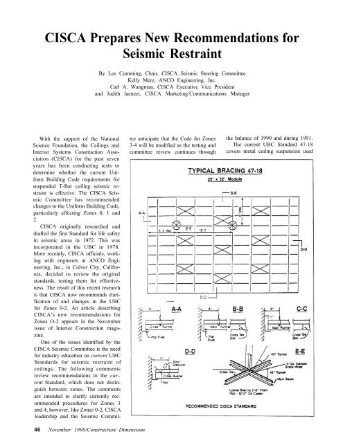
anticipate that the Code <strong>for</strong> Zones the balance of 1990 and during 1991.<br />
3-4 will be modified as the testing and The current UBC Standard 47-18<br />
committee review continues through covers metal ceiling suspension used<br />
46 November 1990/Construction Dimensions
primarily to support acoustical tile or<br />
acoustical lay-in panels as follows:<br />
1. SCOPE<br />
Suspended ceilings which are designed<br />
and constructed to support<br />
ceiling panels or tiles, with or without<br />
lighting fixtures, ceiling mounted air<br />
terminals or other ceiling mounted<br />
services shall comply with the requirements<br />
of this standard.<br />
Exceptions:<br />
1. Ceiling area of 144 square feet<br />
or less surrounded by walls which<br />
connect directly to the structure above<br />
shall be exempt from the lateral load<br />
design requirements of these standards.<br />
2. Ceilings constructed of lath and<br />
plaster or gypsum board, screw or nail<br />
attached to suspended members that<br />
support a ceiling on one level extending<br />
from wall to wall.<br />
2. MINIMUM DESIGN LOADS<br />
1. Lateral Forces:<br />
Such ceiling systems and their<br />
connections to the building structure<br />
shall be designed and constructed to<br />
resist a lateral <strong>for</strong>ce specified in Chapter<br />
23 of the Uni<strong>for</strong>m Building Code.<br />
Connection of lighting fixtures to<br />
the ceiling system shall be designed<br />
<strong>for</strong> a lateral <strong>for</strong>ce of 100% of the<br />
weight of the fixture.<br />
2. Grid Members, Connectors and<br />
Expansion Devices:<br />
The main runners and cross runners<br />
of the ceiling system and their<br />
splices, intersection connectors and<br />
expansion devices shall be designed<br />
and constructed to carry a mean ultimate<br />
test load of not less than 180<br />
pounds or twice the actual load, whichever<br />
is greater, in tension with a 5-<br />
degree misalignment of the members<br />
in any direction, and in compression.<br />
In lieu of 5-degree misalignment, the<br />
load may be applied with a 1-inch<br />
eccentricity on a sample not more<br />
than 24 inches long each side of the<br />
splice. The connections at splices and<br />
intersections all shall be of the mechanical<br />
interlocking type.<br />
Where the composition or configuration<br />
of ceiling system members<br />
or assemblies and their connections<br />
are such that calculations of their<br />
allowable load-carrying capacity cannot<br />
be made in accordance with established<br />
methods of analysis, their<br />
per<strong>for</strong>mance shall be established by<br />
test.<br />
Evaluation of test results shall be<br />
made on the basis of the mean values<br />
resulting from tests of not fewer than<br />
three identical specimens, provided<br />
the deviation of any individual test<br />
result from the mean value does not<br />
exceed plus or minus 10%. The allowable<br />
load-carrying capacity as determined<br />
by test shall not exceed one<br />
half of the mean ultimate test value.<br />
3. Substantiation:<br />
Each ceiling system manufacturer<br />
shall furnish lateral loading capacity<br />
and displacement or elongation characteristics<br />
<strong>for</strong> their systems, indicating<br />
the following:<br />
a. Maximum bracing pattern and<br />
minimum wire sizes.<br />
b. Tension and compression <strong>for</strong>ce<br />
capabilities of main runner splices,<br />
cross runner connections and expansion<br />
devices.<br />
All tests shall be conducted by an<br />
approved testing agency.<br />
3. INSTALLATION<br />
1. Vertical Hangers:<br />
Suspension wires shall not be<br />
smaller than No. 12 gauge spaced at<br />
four feet on center or No. 10 gauge at<br />
five feet on center along each main<br />
runner unless calculations justifying<br />
the increased spacing are provided.<br />
Each vertical wire shall be attached<br />
to the ceiling suspension member and<br />
to the support above with a minimum<br />
of three turns. Any connection device<br />
at the supporting construction shall<br />
be capable of carrying not less than<br />
100 pounds.<br />
Suspension wires shall not hang<br />
more than one in six out-of-plumb<br />
unless countersloping wires are provided.<br />
Wires shall not attach to or<br />
bend around interfering material or<br />
equipment. A trapeze or equivalent<br />
device shall be used where obstructions<br />
preclude direct suspension.<br />
Trapeze suspensions shall be a minimum<br />
of back-to-back 1-1/4 inch coldrolled<br />
channels <strong>for</strong> spans exceeding<br />
48 inches.<br />
2. Perimeter Hangers:<br />
The terminal ends of each cross<br />
runner and main runner shall be<br />
supported independently a maximum<br />
of eight inches from each wall or ceiling<br />
discontinuity with No. 12 gauge<br />
wire or approved wall support.<br />
3. Lateral Force Bracing:<br />
Where substantiating design calculations<br />
are not provided, horizontal<br />
restraints shall be effected by four<br />
No. 12 gauge wires secured to the<br />
main runner within two inches of the<br />
cross runner intersection and splayed<br />
90 degrees from each other at an angle<br />
not exceeding 45 degrees from the<br />
plane of the ceiling. A strut fastened<br />
to the main runner shall be extended<br />
to and fastened to the structural<br />
members supporting the roof or floor<br />
above. The strut shall be adequate to<br />
resist the vertical component induced<br />
by the bracing wires. These horizontal<br />
restraint points shall be placed 12<br />
feet on center in both directions with<br />
the first point within six feet from<br />
each wall. Attachment of the restraint<br />
wires to the structure above shall be<br />
adequate <strong>for</strong> the load imposed.<br />
Lateral <strong>for</strong>ce bracing membranes<br />
shall be spaced to not interface with<br />
horizontal piping or duct work that is<br />
not provided with bracing restraints<br />
<strong>for</strong> horizontal <strong>for</strong>ces. Bracing wires<br />
shall be attached to the grid and to the<br />
structure in such a manner that they<br />
can support a design load of not less<br />
than 200 pounds or the actual design<br />
load, whichever is greater, with a safety<br />
factor of two.<br />
4. Perimeter Members:<br />
Unless perimeter members are a<br />
structural part of the approved system,<br />
wall angles or channels shall be<br />
considered as aesthetic closers and<br />
shall have no structural value assessed<br />
to themselves or their method of attachment<br />
to the wall. Ends of main<br />
runners and cross members shall be<br />
tied together to prevent their spreading.<br />
5. Attachment of Members to the<br />
Perimeter:<br />
48 November 1990/Construction Dimensions
To facilitate installation, main<br />
runners and cross runners may be<br />
attached to the perimeter member at<br />
two adjacent walls with clearance<br />
between the wall and the runners<br />
maintained at the other two walls or<br />
as otherwise shown or described <strong>for</strong><br />
the approved system.<br />
4. LIGHTING FIXTURES<br />
Only “intermediate” and “heavy<br />
duty” ceiling systems as defined in<br />
Paragraph B may be used <strong>for</strong> the<br />
support of lighting fixtures.<br />
All lighting fixtures shall be positively<br />
attached to the suspended ceiling<br />
system. The attachment device<br />
shall have a capacity of 100% of the<br />
lighting fixture weight acting in any<br />
direction.<br />
When “intermediate” systems are<br />
used, No. 12 gauge hangers shall be<br />
attached to the grid members within<br />
three inches of each comer of each<br />
fixture. Tandem fixtures may utilize<br />
common wires.<br />
Where “heavy duty” systems are<br />
used, supplemental hangers are not<br />
required if a 48-inch modular hanger<br />
pattern is followed. When cross runners<br />
are used without supplemental<br />
hangers to support lighting fixtures,<br />
these cross runners must provide the<br />
same carrying capacity as the main<br />
runner.<br />
Lighting fixtures weighing less than<br />
56 pounds shall have, in addition to<br />
the requirements outlined above, two<br />
No. 12 gauge hangers connected from<br />
the fixture housing to the structure<br />
above. These wires may be slack.<br />
Lighting fixtures weighing 56<br />
pounds or more shall be supported<br />
directly from the structure above by<br />
approved hangers.<br />
Pendant-hung lighting fixtures shall<br />
be supported directly from the structure<br />
above using No. 0 gauge wire or<br />
approved alternate support without<br />
using the ceiling suspension system<br />
<strong>for</strong> direct support.<br />
5. MECHANICAL SERVICES<br />
Ceiling mounted air terminals or<br />
services weighing less than 20 pounds<br />
shall be positively attached to the<br />
ceiling suspension main runners or to<br />
cross runners with the same carrying<br />
capacity as the main runners.<br />
Terminals or services weighing 20<br />
pounds but not more than 56 pounds,<br />
in addition to the above, shall have<br />
two No. 12 gauge hangers connected<br />
from the terminal or service to the<br />
ceiling system hangers or to the structure<br />
above. These wires may be slack<br />
Terminals or services weighing<br />
more than 56 pounds shall be supported<br />
directly from the structure<br />
above by approved hangers.<br />
6. PARTITIONS<br />
Where the suspended ceiling system<br />
is required to provide lateral<br />
support <strong>for</strong> permanent or relocatable<br />
partitions, the connection of the partition<br />
to the ceiling system, the ceiling<br />
system members and their connections,<br />
and the lateral <strong>for</strong>ce bracing<br />
shall be designed to support the reaction<br />
<strong>for</strong>ce of the partition from prescribed<br />
loads applied perpendicular<br />
to the face of the partition. These<br />
partition reaction <strong>for</strong>ces shall be in<br />
addition to the loads described in<br />
Section 47.1811 of the Uni<strong>for</strong>m Building<br />
Code. Partition connectors, the<br />
suspended ceiling system and the lateral<br />
<strong>for</strong>m bracing shall all be engineered<br />
to suit the individual partition<br />
application and shall be shown or<br />
defined in the drawing or specifications.<br />
7. DRAWINGS AND SPECIFICA-<br />
TIONS<br />
The drawings shall clearly identify<br />
all systems and shall define or show<br />
all supporting details, lighting fixture<br />
attachment, lateral <strong>for</strong>ce bracing,<br />
partition bracing, etc. Such definition<br />
may be by reference to this standard,<br />
or approved system, in whole or in<br />
part. Deviations or variations must<br />
be shown or defined in detail.<br />
Conclusion<br />
<strong>CISCA</strong> officials, working with<br />
ANCO Engineers, will review the<br />
above stated standards during the<br />
course of 1990-1991 with the intention<br />
of modifying the current recommendations<br />
so that life safety can be<br />
provided in a cost-effective manner.<br />
The final approval process includes<br />
review by the International Conference<br />
of Building Officials (ICBO) who<br />
publish the Uni<strong>for</strong>m Building Code,<br />
the Building Officials and Code Administrators<br />
International (BOCA)<br />
who publish the National Building<br />
Code, and the Southern Building Code<br />
Congress International (SBCCI), who<br />
publish the Standard Building Code.<br />
<strong>CISCA</strong> will continue to provide in<strong>for</strong>mation<br />
on developments in this<br />
critical area.