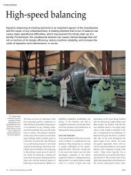
Reducing pressure— increasing efficiency
Reducing pressure— increasing efficiency
Reducing pressure— increasing efficiency

Create successful ePaper yourself
Turn your PDF publications into a flip-book with our unique Google optimized e-Paper software.
PANORAMA<br />
<strong>Reducing</strong> <strong>pressure—</strong><br />
<strong>increasing</strong> <strong>efficiency</strong><br />
In several industrial processes, a fluid under high pressure must be throttled to suit subsequent<br />
process steps. Typically, conventional pressure-reducing valves are used to dissipate, and<br />
consequently waste, this hydraulic energy. Hydraulic power recovery turbines (HPRT’s) can<br />
convert the excess pressure into mechanical shaft energy and increase the overall process<br />
<strong>efficiency</strong>. Sulzer Pumps has years of experience in using reverse running pumps as turbines<br />
as an economical solution to recover energy.<br />
26<br />
| Sulzer Technical Review 1/2011<br />
Generally, pumps are a means of<br />
fluid transport that convert mechanical<br />
energy into hydraulic energy; i.e., pumps<br />
increase fluid pressure. When process<br />
conditions call for pressure to be dissipated,<br />
a pump running backwards may<br />
be used to capture that otherwise wasted<br />
energy. The reverse running mode<br />
converts hydraulic energy into mechanical<br />
energy and can be used to drive a<br />
generator or to assist the driver of other<br />
rotating machines. By using an HPRT,<br />
as much as 85% of the energy otherwise<br />
wasted in a throttling valve can be<br />
captured. When modified standard<br />
pumps are used as HPRTs, investment<br />
costs are low as compared with those<br />
for conventional turbines. Energy<br />
recovery may merit consideration even<br />
if the pressure reduction is relatively<br />
small.<br />
Almost any centrifugal pump can<br />
operate as a turbine. The direction of<br />
fluid flow is reversed compared with<br />
that in a pump. The pump discharge<br />
flange becomes the inlet of the HPRT,<br />
and the pump suction flange becomes<br />
the outlet, or exhaust. For larger HPRTs,<br />
the interior of the pump casing is<br />
modified to provide uniform flow to the<br />
runner.<br />
Energy recovery<br />
Conventional hydraulic turbines can be<br />
of axial, mixed, or radial flow type, and<br />
single or multistage. Differential head,<br />
flow, and speed govern which type is<br />
applied for a particular application. These<br />
three parameters determine the specific<br />
speed of a hydraulic machine. Specific<br />
speed is a characteristic number for each<br />
pump or turbine, and it increases with<br />
higher flow and lower head. High specific<br />
speed (axial flow) runners are used for<br />
lower head and higher flow, as in runof-river<br />
hydropower plants 1.<br />
Single-stage or multistage radial-flow<br />
or mixed-flow turbines are used for<br />
higher heads. For very low flow with<br />
high head, an impulse, or Pelton turbine<br />
may be an appropriate choice. The power<br />
output of a hydraulic power recovery<br />
device is a function of flow and head.<br />
Reaction type turbines are used for power<br />
ratings between 500 kW and about<br />
700 MW in hydropower plants.<br />
In some industrial installations, such<br />
as reverse osmosis plants, petroleum<br />
refineries, fertilizer plants, and gas<br />
treating facilities, some processes may<br />
need to operate at high pressure. For<br />
example, amine contactors are widely<br />
used to scrub CO2 and H2S from natural<br />
gas. The contactor operates at pipeline<br />
pressure. Then pressure is reduced to<br />
flash out various components of the<br />
process stream. Usually throttling devices<br />
(valves, orifices etc.) are used to reduce<br />
the pressure. Single-stage HPRTs can be<br />
used to recover that energy. In refining<br />
hydro treaters, multistage HPRTs may be<br />
needed due to the large pressure drop<br />
required.<br />
Know-how for correct layout<br />
When planning the use of a pump as<br />
turbine, it is essential to know the differences<br />
in machine performance when<br />
reversing flow direction and sense of<br />
rotation. For equal rotational speed and<br />
runner diameter, the following general<br />
differences are noted 2:<br />
• The <strong>efficiency</strong> at the best operating<br />
point of the turbine corresponds<br />
4335
approximately to that of the pump, or<br />
it can be slightly higher depending on<br />
the size of the machine.<br />
• The <strong>efficiency</strong> curve under overload<br />
conditions drops more slowly in the<br />
turbine than in the pump mode since<br />
the losses are associated with a high<br />
power.<br />
• The best <strong>efficiency</strong> point of the turbine<br />
is located at higher flow rate and higher<br />
head. That means the capacity is higher<br />
in the turbine mode than when<br />
pumping.<br />
• In most instances, the shaft power at<br />
the best operating point of the turbine<br />
is somewhat higher than that at the<br />
corresponding point of the pump.<br />
• Susceptibility to cavitation is lower in<br />
the turbine than in the pumping mode,<br />
since the low pressure zone is at the<br />
runner outlet in turbine mode.<br />
Sulzer has provided hundreds of HPRTs<br />
3 in various configurations and has<br />
established methods to calculate HPRT<br />
performance from pump performance.<br />
However, if exact data are necessary, it<br />
is essential to test the HPRT. Turbine<br />
testing requires a lot of equipment and<br />
thus costs measurably more than pump<br />
testing 4 .<br />
A booster pump with sufficient power<br />
must be used to provide the inlet flow<br />
and high inlet pressure. The output power<br />
of the HPRT must be measured with a<br />
calibrated generator, torque meter, or<br />
dynamometer. Measurements of power,<br />
flow, and pressure are used to calculate<br />
turbine <strong>efficiency</strong>. To avoid cavitation at<br />
the HPRT outlet, backpressure at the<br />
outlet must be controlled.<br />
Considering the complete system<br />
Determination of the runaway speed is<br />
essential for the operation of the reverse<br />
running pump. Runaway is the operation<br />
at maximum speed and no load.<br />
This is an exceptional case that occurs<br />
when the generator loses its grid connection<br />
due to a power outage or lightning<br />
strike. Runaway could occur in fractions<br />
of a second and has to be considered<br />
in the layout of a hydraulic system.<br />
Runaway speed of a radial machine<br />
0 1 2<br />
2<br />
0 2<br />
QPop: QTop:<br />
2 Characteristics of a pump impeller in pump<br />
and turbine mode (n = constant, D = constant).<br />
The best <strong>efficiency</strong> point (BEP) of the turbine<br />
is shifted to higher head and flow rate.<br />
1 Large water turbines can have a power rating of 700 MW or more. At much smaller ratings, conventional pumps running as turbines<br />
are an economical solution for pressure reduction in industrial processes.<br />
© Andrey Shchekalev | Dreamstime.com<br />
HT / HP<br />
1<br />
0<br />
PT / PP<br />
1<br />
0<br />
-0.5<br />
HT<br />
HP<br />
ηT<br />
ηP<br />
PT<br />
PP<br />
1<br />
ηT / ηP<br />
0<br />
QT/QP<br />
PANORAMA<br />
Pump<br />
Turbine<br />
Anticipation Range<br />
Sulzer Technical Review 1/2011 |<br />
27
PANORAMA<br />
3 In many cases, a single-stage HPRT is used to capture the process stream energy and drive a multistage pump.<br />
4 Typical HPRT test setup in a closed loop.<br />
Electric<br />
Power<br />
Supply<br />
Electric<br />
Power<br />
Grid<br />
Electrical<br />
Power<br />
Measurement<br />
Pump discharge<br />
pressure<br />
Pl<br />
Throttle valve<br />
Turbine inlet pressure<br />
can be between 140% and 200% of<br />
the nominal speed, depending on the<br />
specific speed and the rated conditions.<br />
This condition should be taken into<br />
account for generator operation and in<br />
the selection of the trip device that<br />
operates at transient conditions. If the<br />
HPRT is used to drive a generator, it<br />
may be prudent to use a gear reducer<br />
and drive the generator at four- or sixpole<br />
(1500 RPM or 1000 RPM at 50 Hz<br />
power frequency, 1800 RPM or 1200 RPM<br />
at 60Hz power frequency) speeds but<br />
mechanically design the generator rotor<br />
for two-pole speed (3000 RPM at 50 Hz,<br />
3600 RPM at 60Hz).<br />
Motor<br />
Pl Pl<br />
Electrical<br />
Power<br />
Measurement<br />
Booster<br />
Pump<br />
Turbine<br />
Generator<br />
P<br />
Pump suction<br />
pressure<br />
Suction<br />
valve<br />
Turbine outlet pressure<br />
28 | Sulzer Technical Review 1/2011<br />
Vacuum<br />
Pump<br />
Flow meter<br />
(Venturi or magnetic)<br />
Suppression<br />
Tank<br />
Flow<br />
Fluid temperature<br />
Air pressure<br />
supply<br />
Vent<br />
Fill<br />
Drain<br />
Back pressure<br />
valve<br />
Hydropower turbines have flow<br />
control devices, such as wicket gates,<br />
which help to avoid high pressure surge<br />
during transient conditions. In process<br />
HPRT applications, the turbine bypass<br />
is always slightly open and is quickly<br />
adjusted to maintain inlet vessel level<br />
control when the turbine inlet valve trips.<br />
Operating with two-phase flow<br />
Care must be taken when starting up an<br />
HPRT. When an HPRT is driving a generator,<br />
it is normally spun-up to near<br />
operating speed, and then as the speed<br />
nears synchronous speed, the generator<br />
is switched to the power grid, which<br />
provides a load. Without load, the HPRT<br />
may quickly overspeed.<br />
Process control is important when<br />
applying HPRTs. If the pressure in the<br />
exhaust vessel is lowered by 20%, head<br />
across the turbine increases, and it will<br />
generate 20% more power than at the<br />
rated flow and head. For that reason, it<br />
is often prudent to oversize the HPRTs,<br />
shaft torque capacity to take into account<br />
various system upsets in pressure control.<br />
Processes have to be started before the<br />
HPRT can be brought on stream. Often,<br />
there will be a full-size pump with motor<br />
driver to get the process started and a<br />
parallel HPRT clutch motor pump that<br />
is used during normal operation 5 6.<br />
For processes with entrained gas or<br />
vapor (natural gas treating, fertilizer<br />
plants, hydrotreaters, etc.), a small volume<br />
percent of gas at the high-pressure side<br />
will turn into a measurable volume at<br />
the low-pressure side. This gas volume<br />
at the outlet may influence the size of<br />
the HPRT. The high gas volume in the<br />
exhaust may not be an issue if the shaft<br />
is robust, the runner is made of cavitation-resistant<br />
materials, and the wear<br />
parts are hardened to reduce contact<br />
damage. However, gas bubbles in the<br />
seal chamber will surely do damage to<br />
the mechanical seals. Dual seals within<br />
Plan 53 or 54 are therefore recommended<br />
for process HPRTs to assure that the<br />
mechanical seals operate in a controlled,<br />
liquid state.<br />
Application in hydrocarbon<br />
processing<br />
A large Brazilian oil company is using<br />
pumps as turbines instead of throttle<br />
valves and is thus recovering energy.<br />
In one case, liquid charged with gas<br />
must be expanded in a scrubbing tower.<br />
Sulzer worked with oil company engineers<br />
to understand the multiphase flow.<br />
That knowledge was then used to design<br />
the HPRT’s runner and rotor. The experience<br />
of Sulzer Pumps in designing such<br />
HPRTs helped to find a solution for these<br />
challenging conditions.<br />
Between the inlet and outlet of a<br />
turbine, the pressure drops in very short<br />
time. Gas dissolved in the fluid at high<br />
pressure diffuses out of the liquid causing<br />
gas bubbles to form, resulting in twophase<br />
flow. The required pressure reduction<br />
is from 74.8 bar (1080 psi) to 14.8bar<br />
(210psi). A five-stage HPRT with one<br />
dummy stage was chosen, so that a<br />
further stage may be fitted for smaller<br />
flow rates in the future 7. The continuous<br />
power of 258 kW recovered from the<br />
expansion assists the 870-kW motor<br />
driving the pressure <strong>increasing</strong> pump. A<br />
pump running as a turbine is difficult<br />
5 HPRT equipment layout: Driving the<br />
generator at reduced speed can save it on<br />
overspeed caused by a sudden power loss.<br />
Pump<br />
HPRT<br />
Gear<br />
reducer<br />
Motor<br />
Clutch<br />
Generator<br />
HPRT
6 Some HPRT trains are so long that the baseplate is split at one coupling to facilitate<br />
shipping, lifting, and installation. Setup: HT-MSD – clutch – motor (missing) – MSD pump.<br />
to regulate. Depending upon the pressure<br />
drop and application, an HPRT flow<br />
rate may be established amounting to<br />
80%–90% of the effective throughput.<br />
The remaining 10%–20% of the flow is<br />
expanded via a bypass valve and is used<br />
to control the vessel level supplying the<br />
HPRT.<br />
During plant startup, the turbine<br />
cannot perform work and may actually<br />
8 Gas plant: MSD pump – motor – clutch – HST turbine.<br />
consume energy. If the motor must be<br />
used for startup, an overrunning clutch<br />
prevents the motor from having to put<br />
additional energy into the turbine during<br />
this phase. Once the hydraulic energy<br />
at the inlet to the HPRT is sufficient, the<br />
turbine runs up to the motor speed. The<br />
overrunning clutch now ensures that the<br />
HPRT cannot run faster and supplies its<br />
hydraulic energy to the drive train.<br />
Amine<br />
contactor<br />
Startup<br />
pump<br />
Level controller<br />
Sour gas<br />
Startup<br />
motor<br />
Sweet gas stream<br />
Pump Motor<br />
Bypass<br />
Lean amine stream<br />
7 A gas-scrubbing HPRT application can recover more than 2 MW.<br />
Clutch<br />
Short payback times<br />
In many industrial processes, hydraulic<br />
power recovery turbines (HPRTs 8 )<br />
can provide substantial savings with a<br />
short payback period. It is not uncommon<br />
to find that over 1.5MW can be re -<br />
covered. Careful attention to process<br />
conditions and HPRT controls assures<br />
reliable, useful operation for years of<br />
service.<br />
HPRT<br />
PANORAMA<br />
Stripper<br />
Ron Adams<br />
Sulzer Pumps<br />
800 Koomey Road<br />
Brookshire, TX 77423<br />
USA<br />
Phone +1 281 934 6029<br />
ron.adams@sulzer.com<br />
John Parker<br />
Sulzer Pumps<br />
800 Koomey Road<br />
Brookshire, TX 77423<br />
USA<br />
Phone +1 281 934 6011<br />
johns.parker@sulzer.com<br />
Sulzer Technical Review 1/2011 |<br />
29