Installation/Operation Guide - Dyers RV and Trailer
Installation/Operation Guide - Dyers RV and Trailer
Installation/Operation Guide - Dyers RV and Trailer

You also want an ePaper? Increase the reach of your titles
YUMPU automatically turns print PDFs into web optimized ePapers that Google loves.
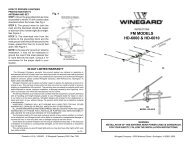
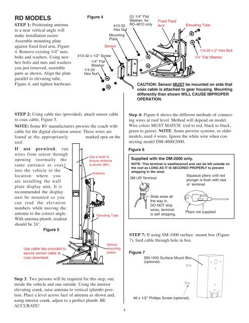
RD MODELS<br />
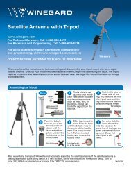
STEP 1: Positioning antenna<br />
to a near vertical angle will<br />
make installation easier.<br />
Assemble mounting plate<br />
against fixed feed arm, Figure<br />
4. Remove existing 1/4” nuts,<br />
bolts <strong>and</strong> washers. Using new<br />
hex bolts <strong>and</strong> nuts <strong>and</strong> washers<br />
you just removed, assemble<br />
parts as shown. Align the plate<br />
parallel to elevating tube,<br />
Figure 4, <strong>and</strong> tighten hardware.<br />
Figure 4<br />
#10-32<br />
Hex Nut<br />
Mounting<br />
Plate<br />
Sensor<br />
#10-32 x 1/2" Screw<br />
1/4" Flat<br />
Washer<br />
1/4-20<br />
Hex Nut<br />
(2) 1/4" Flat<br />
Washer, for<br />
RD-4610 only<br />
Fixed Feed<br />
Arm<br />
Elevating Tube<br />
1/4-20 x 2" Hex Bolt<br />
1/4" Flat Washer<br />
CAUTION: Sensor MUST be mounted on side that<br />
coax cable is attached to gear housing. Mounting<br />
differently than shown WILL CAUSE IMPROPER<br />
OPERATION.<br />
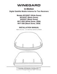
STEP 2: Using cable ties (provided), attach sensor cable<br />
to coax cable, Figure 5.<br />
NOTE: Some <strong>RV</strong> manufacturers prewire the coach with<br />
cable for the digital elevation sensor. These wires are<br />
found at the appropriately marked spot on the<br />
roof.<br />
If not prewired, run<br />
wires from sensor through<br />
Use a level to<br />
opening (normally the<br />
ensure antenna<br />
same entrance as coax)<br />
is plumb (90 o )<br />
into the vehicle to the<br />
Antenna<br />
location where you<br />
are installing the wall<br />
plate display unit. It is<br />
recommended the display<br />
unit be mounted so you<br />
can read the elevation<br />
numbers while moving the<br />
antenna to the correct angle.<br />
Elevating Tube<br />
With antenna plumb, readout<br />
should be 24°.<br />
Figure 5<br />
Use cable ties provided to<br />
secure sensor cable to<br />
coax downlead.<br />
Sensor<br />
mounting<br />
plates<br />
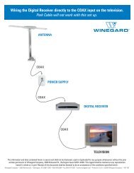
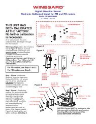
Step 4: Figure 6 shows the different methods of connecting<br />
wires at roof level. Method will depend on model.<br />
Wire colors MUST MATCH (red to red, black to black,<br />
green to green). NOTE: Some prewire systems, or older<br />
models, used 4 wires. Ignore the white wire when connecting<br />
model DM-4000/2000.<br />
Figure 6<br />
Supplied with the DM-2000 only.<br />
NOTE: This terminal is weatherproof <strong>and</strong> can be left outside on<br />
the roof as LONG AS IT IS SECURED PROPERLY to prevent<br />
whipping in the wind.<br />
Squeeze pliers until red<br />
3M UR Terminal<br />
plunger is flush with rest<br />
of terminal.<br />
Slide wires all<br />
the way in.<br />
DO NOT strip<br />
wires, terminal<br />
is self stripping.<br />
Pliers not supplied<br />
STEP 7: If using SM-1000 surface mount box (Figure<br />
7), feed cable through hole in box.<br />
Figure 7<br />
SM-1000 Surface Mount Box<br />
(optional).<br />
Step 3: Two persons will be required for this step, one<br />
inside the vehicle <strong>and</strong> one outside. Using the interior<br />
elevating crank, raise antenna to vertical (plumb) position.<br />
Place a level across face of antenna as shown <strong>and</strong>,<br />
using interior crank, adjust to a perfect plumb. BE<br />
ACCURATE!<br />
2<br />
#6 x 1/2” Phillips Screw (optional).