Installation/Operation Guide - Dyers RV and Trailer
Installation/Operation Guide - Dyers RV and Trailer
Installation/Operation Guide - Dyers RV and Trailer

Create successful ePaper yourself
Turn your PDF publications into a flip-book with our unique Google optimized e-Paper software.
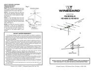
WINEGARD<br />
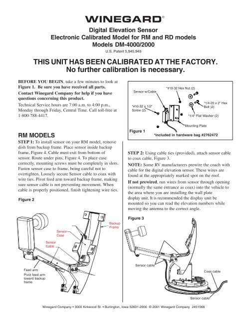
Digital Elevation Sensor<br />
Electronic Calibrated Model for RM <strong>and</strong> RD models<br />
Models DM-4000/2000<br />
U.S. Patent 5,945,945<br />
THIS UNIT HAS BEEN CALIBRATED AT THE FACTORY.<br />
No further calibration is necessary.<br />
®<br />
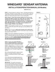
BEFORE YOU BEGIN, take a few minutes to look at<br />
Figure 1. Be sure you have received all parts.<br />
Contact Winegard Company for help if you have<br />
questions concerning this product.<br />
Technical Service hours are 7:00 a.m. to 4:00 p.m.,<br />
Monday through Friday, Central Time. Call toll-free at<br />
1-800-788-4417.<br />
Sensor w/Cable<br />
*#10-32 x 1/2"<br />
Screw (2)<br />
*#10-32 Hex Nut (2)<br />
*1/4-20 x 2" Hex<br />
Bolt )2)<br />
*1/4" Flat Washer (2)<br />
RM MODELS<br />
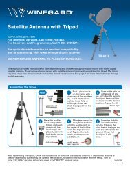
STEP 1: To install sensor on your RM model, remove<br />
dish from backup frame. Place sensor inside backup<br />
frame, Figure 4. Cable must exit from bottom of<br />
sensor. Route under pins, Figure 4. To place case<br />
correctly, mounting screws must be completely in slots.<br />
Fasten sensor case to frame, being careful not to<br />
overtighten. Loosely secure Sensor cable to coax with<br />
wire ties. Pivot feed arm toward backup frame, making<br />
sure sensor cable is not preventing movement. When<br />
cable is properly positioned, finish tightening wire ties.<br />
Figure 2<br />
Figure 1<br />
*Mounting Plate<br />
*included in hardware bag #2762472<br />
STEP 2: Using cable ties (provided), attach sensor cable<br />
to coax cable, Figure 3.<br />
NOTE: Some <strong>RV</strong> manufacturers prewire the coach with<br />
cable for the digital elevation sensor. These wires are<br />
found at the appropriately marked spot on the roof.<br />
If not prewired, run wires from sensor through opening<br />
(normally the same entrance as coax) into the vehicle to<br />
the area where you are installing the wall plate<br />
display unit. It is recommended the display unit be<br />
mounted so you can read the elevation numbers while<br />
moving the antenna to the correct angle.<br />
Sensor<br />
Cable<br />
Sensor<br />
Case<br />
Backup<br />
Frame<br />
Figure 3<br />
Feed arm<br />
Pivot feed arm<br />
toward backup<br />
frame.<br />
Sensor cable<br />
Coax cable<br />
Sensor cable<br />
Winegard Company • 3000 Kirkwood St. • Burlington, Iowa 1 52601-2000 © 2001 Winegard Company 2451568
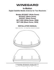
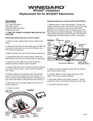
RD MODELS<br />
STEP 1: Positioning antenna<br />
to a near vertical angle will<br />
make installation easier.<br />
Assemble mounting plate<br />
against fixed feed arm, Figure<br />
4. Remove existing 1/4” nuts,<br />
bolts <strong>and</strong> washers. Using new<br />
hex bolts <strong>and</strong> nuts <strong>and</strong> washers<br />
you just removed, assemble<br />
parts as shown. Align the plate<br />
parallel to elevating tube,<br />
Figure 4, <strong>and</strong> tighten hardware.<br />
Figure 4<br />
#10-32<br />
Hex Nut<br />
Mounting<br />
Plate<br />
Sensor<br />
#10-32 x 1/2" Screw<br />
1/4" Flat<br />
Washer<br />
1/4-20<br />
Hex Nut<br />
(2) 1/4" Flat<br />
Washer, for<br />
RD-4610 only<br />
Fixed Feed<br />
Arm<br />
Elevating Tube<br />
1/4-20 x 2" Hex Bolt<br />
1/4" Flat Washer<br />
CAUTION: Sensor MUST be mounted on side that<br />
coax cable is attached to gear housing. Mounting<br />
differently than shown WILL CAUSE IMPROPER<br />
OPERATION.<br />
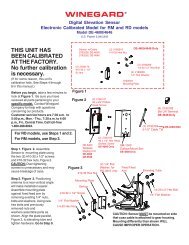
STEP 2: Using cable ties (provided), attach sensor cable<br />
to coax cable, Figure 5.<br />
NOTE: Some <strong>RV</strong> manufacturers prewire the coach with<br />
cable for the digital elevation sensor. These wires are<br />
found at the appropriately marked spot on the<br />
roof.<br />
If not prewired, run<br />
wires from sensor through<br />
Use a level to<br />
opening (normally the<br />
ensure antenna<br />
same entrance as coax)<br />
is plumb (90 o )<br />
into the vehicle to the<br />
Antenna<br />
location where you<br />
are installing the wall<br />
plate display unit. It is<br />
recommended the display<br />
unit be mounted so you<br />
can read the elevation<br />
numbers while moving the<br />
antenna to the correct angle.<br />
Elevating Tube<br />
With antenna plumb, readout<br />
should be 24°.<br />
Figure 5<br />
Use cable ties provided to<br />
secure sensor cable to<br />
coax downlead.<br />
Sensor<br />
mounting<br />
plates<br />
Step 4: Figure 6 shows the different methods of connecting<br />
wires at roof level. Method will depend on model.<br />
Wire colors MUST MATCH (red to red, black to black,<br />
green to green). NOTE: Some prewire systems, or older<br />
models, used 4 wires. Ignore the white wire when connecting<br />
model DM-4000/2000.<br />
Figure 6<br />
Supplied with the DM-2000 only.<br />
NOTE: This terminal is weatherproof <strong>and</strong> can be left outside on<br />
the roof as LONG AS IT IS SECURED PROPERLY to prevent<br />
whipping in the wind.<br />
Squeeze pliers until red<br />
3M UR Terminal<br />
plunger is flush with rest<br />
of terminal.<br />
Slide wires all<br />
the way in.<br />
DO NOT strip<br />
wires, terminal<br />
is self stripping.<br />
Pliers not supplied<br />
STEP 7: If using SM-1000 surface mount box (Figure<br />
7), feed cable through hole in box.<br />
Figure 7<br />
SM-1000 Surface Mount Box<br />
(optional).<br />
Step 3: Two persons will be required for this step, one<br />
inside the vehicle <strong>and</strong> one outside. Using the interior<br />
elevating crank, raise antenna to vertical (plumb) position.<br />
Place a level across face of antenna as shown <strong>and</strong>,<br />
using interior crank, adjust to a perfect plumb. BE<br />
ACCURATE!<br />
2<br />
#6 x 1/2” Phillips Screw (optional).
CAUTION:<br />
If using +12 VDC, it must be FILTERED!<br />
If using non-filtered +12 VDC, the product will be<br />
damaged <strong>and</strong> Warranty voided.<br />
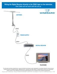
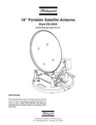
STEP 8: Connect wires coming from sensor on roof to<br />
wall plate display in vehicle, Figure 8. It is important to<br />
properly connect the wires at the roof <strong>and</strong> the wall plate.<br />
(Plug will click when inserted properly.) The system is<br />
designed to use a 9 volt battery OR +12 VDC from<br />
vehicle. Do not use both! IMPROPER WIRING WILL<br />
CAUSE DAMAGE TO THE PRODUCT.<br />
STEP 9: Pressing the button when the antenna is in a<br />
vertical position should display 24 (can be plus [+] or<br />
minus [-] 1 degree). Display will automatically turn off<br />
after 1 minute.<br />
Figure 8<br />
Cable <strong>and</strong> plug<br />
from roof<br />
sensor unit;<br />
plugs into<br />
sensor readout<br />
cable.<br />
Sensor-to-readout<br />
cable<br />
Cut here for prewire<br />
applications<br />
Readout assembly<br />
Power cable harness<br />
Red=Positive<br />
Black=Negative<br />
(This cable not used with<br />
9 V battery)<br />
STEP 10: Check connectors <strong>and</strong> cable entry points. Be<br />
sure these areas are properly sealed to prevent water<br />
damage to the system <strong>and</strong> property.<br />
ERROR CODES on display<br />
LL ............... Low Limit<br />
(antenna too low)<br />
HL .............. High Limit<br />
(antenna past range of readout)<br />
LO ............ Low Battery<br />
ER .... Connection Fault<br />
(check wiring & connections)<br />
OPERATING INSTRUCTIONS<br />
STEP 1: Using satellite receiver, find correct elevation<br />
for your location. See the receiver manual for details of<br />
setup information.<br />
STEP 2: Press button on Winegard digital display wall<br />
plate. If antenna is in travel position, the display will<br />
show HL for High Limit (RD models), LL for Low Limit<br />
(RM models).<br />
STEP 3: Crank elevation h<strong>and</strong>le to raise antenna. Stop<br />
when readout displays correct elevation for your<br />
location.(Found on receiver setup menu.)<br />
STEP 4: Rotate antenna VERY SLOWLY until correct<br />
satellite signal is acquired. NOTE: Rotate 3° <strong>and</strong> stop.<br />
DO NOT rotate continuously even if your are rotating<br />
slowly. If the elevation angle has changed, it could be due<br />
to the following —<br />
• Vehicle is not parked level.<br />
• Antenna system mounted on slightly sloped roof. If<br />
this is the reason, after you have rotated the antenna<br />
to the appproximate correct compass direction, adjust<br />
to correct elevation <strong>and</strong> continue search.<br />
3<br />
Special Notes: When you have found the satellite signal,<br />
adjust the antenna up/down <strong>and</strong> right/left for the strongest<br />
signal your receiver displays. Due to variation in<br />
receivers <strong>and</strong> installation methods, you may find the<br />
elevation numbers after peaking on strongest signal no<br />
longer match what the receiver display recommended.<br />
This is normal. The elevation sensor should always get<br />
you close enough to pick up a signal to peak on. If<br />
display turns off while you’re searching, just push button<br />
for another minute of operation. With a little practice,<br />
most users find the signal in 30 to 50 seconds.<br />
Replacement Parts<br />
For replacement parts, contact Winegard Company.<br />
Customer Service hours are 7:00 a.m. to 5:00 p.m.,<br />
Monday - Friday, Central Time. Call toll-free<br />
1-800-288-8094. Credit card only, $5.00 minimum order.<br />
Refer to Figure 1 on page 1 of this instruction sheet for<br />
part numbers.
Printed in U.S.A. Winegard Company • 3000 Kirkwood St. • Burlington, Iowa 52601-2000 © 2001 Winegard Company 2451568<br />
4