Vivotek SD8121 Installation Guide - Use-IP
Vivotek SD8121 Installation Guide - Use-IP
Vivotek SD8121 Installation Guide - Use-IP

Create successful ePaper yourself
Turn your PDF publications into a flip-book with our unique Google optimized e-Paper software.
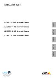
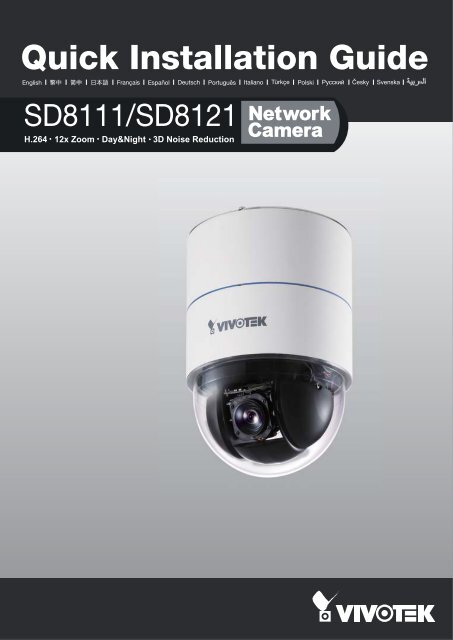
Quick <strong>Installation</strong> <strong>Guide</strong><br />
English 繁 中 簡 中 日 本 語 Français Español Deutsch Português Italiano Türkçe Polski Русский Česky Svenska<br />
SD8111/<strong>SD8121</strong><br />
H.264 12x Zoom Day&Night 3D Noise Reduction
Warning Before <strong>Installation</strong><br />
English<br />
Power off the Network Camera as<br />
soon as smoke or unusual odors are<br />
detected.<br />
Keep the Network Camera away<br />
from water. If the Network Camera<br />
becomes wet, power off immediately.<br />
Contact your distributor in the event of<br />
occurrence.<br />
Contact your distributor in the event of<br />
occurrence.<br />
Do not place the Network Camera<br />
around heat sources, such as a<br />
television or oven.<br />
Refer to your user's manual for the<br />
operating temperature.<br />
Keep the Network Camera away from<br />
direct sunlight.<br />
Do not place the Network Camera in<br />
high humidity environments.<br />
EN - 1
Do not place the Network Camera on<br />
unsteady surfaces.<br />
Do not touch the Network Camera<br />
during a lightning storm.<br />
Do not disassemble the Network<br />
Camera.<br />
Do not drop the Network Camera.<br />
Do not insert sharp or tiny objects<br />
into the Network Camera.<br />
EN - 2
510000210G<br />
1<br />
Package Contents<br />
English<br />
SD8111 / <strong>SD8121</strong><br />
Hard Ceiling Mount Bracket and<br />
Decoration Ring<br />
Cable Connector (Power, Video Out,<br />
Mic In, Audio Out, Ground)<br />
DI/DO Cable Connector<br />
Power Adaptor<br />
Fixing Plate<br />
Quick <strong>Installation</strong> <strong>Guide</strong> /<br />
Warranty Card<br />
Software CD<br />
EN - 3
2<br />
Physical Description<br />
SD/SDHC Card Slot<br />
Lens<br />
Dome Cover<br />
Record the MAC address before<br />
installing the camera.<br />
0002D107258A<br />
Ethernet 10/100 RJ45 Socket<br />
Reset Button<br />
Restore Button<br />
Cable Connector Socket<br />
EN - 4
3<br />
Hardware <strong>Installation</strong><br />
English<br />
Follow the steps below to install the Network Camera to the ceiling:<br />
1. Detach the Decoration Ring from the Hard Ceiling Mount Bracket.<br />
2. Align the three holes on the Mount Bracket, mark the screws locations on the ceiling.<br />
3. Drill three pilot holes into the ceilling and hammer the plastic anchors into the holes.<br />
4. Fix the Mount Bracket with three screws.<br />
1 4<br />
2<br />
3<br />
EN - 5
5. Put the decoration ring onto the dome body.<br />
6. Insert the fixing plate into the groove as shown below.<br />
7. Align the three holes to screw the fixing plate to the dome base.<br />
5 6<br />
0002D107258A<br />
7<br />
0002D107258A<br />
EN - 6
8. If you have external devices such as sensors and alarms, connect them to the general<br />
I/O terminal block. Then connect the cable connector and Ethernet cable to the dome<br />
base.<br />
9. Align plate A and plate B, use hole a ~ c to hook the Network Camera on the ceiling<br />
mount bracket.<br />
English<br />
Pin Definitions of Cable Connector<br />
2 4<br />
22<br />
8<br />
1 3<br />
12: DI 0<br />
13: DI 2<br />
14: DI 1<br />
15: DI 3<br />
16: DO<br />
21<br />
0002D107258A<br />
A<br />
8<br />
9<br />
B<br />
9<br />
a<br />
0002D107258A<br />
b<br />
c<br />
EN - 7
POWER COLLISION<br />
1 2 3 4 5<br />
LINK<br />
RECEIVE<br />
PARTITION<br />
10. Tighten the screw on the fixing plate.<br />
11. Align the three holes to mount the decoration ring.<br />
10<br />
11<br />
12. Connect the cables and make the network deployment.<br />
Ground<br />
Power Cord Socket<br />
BNC Video Out<br />
Microphone In (pink)<br />
Audio Out (green)<br />
Ethernet 10/100 RJ45 Plug<br />
Ethernet Switch<br />
EN - 8
4<br />
Assigning an <strong>IP</strong> Address<br />
English<br />
1. Install “<strong>Installation</strong> Wizard 2” from the Software Utility directory on the software CD.<br />
2. The program will conduct an analysis of your network environment. After your network is<br />
analyzed, please click on the “Next” button to continue the program.<br />
<strong>Installation</strong><br />
Wizard 2<br />
3. The program will search for VIVOTEK Video Receivers, Video Servers, and Network<br />
Cameras on the same LAN.<br />
4. After searching, the main installer window will pop up. Click on the MAC that matches the<br />
one labeled on the bottom of your device to connect to the Network Camera via Internet<br />
Explorer.<br />
0002D107258A<br />
00-02-D1-07-25-8A 192.168.5.151 <strong>SD8121</strong><br />
0002D107258A<br />
EN - 9
5<br />
Ready to <strong>Use</strong><br />
1. Access the Network Camera on the LAN.<br />
2. Retrieve live video through a web browser or recording software.<br />
2010/06/09 10:25:23<br />
For further setup, please refer to the user's manual on the software CD.<br />
EN - 10
P/N: 625012000G Ver.1.0<br />
Copyright c 2010 VIVOTEK INC. All rights reserved.