Ion Beam Treatment of Functional Layers in Thin-Film Silicon Solar ...
Ion Beam Treatment of Functional Layers in Thin-Film Silicon Solar ...
Ion Beam Treatment of Functional Layers in Thin-Film Silicon Solar ...

You also want an ePaper? Increase the reach of your titles
YUMPU automatically turns print PDFs into web optimized ePapers that Google loves.
2.1 <strong>Ion</strong> beam treatment<br />
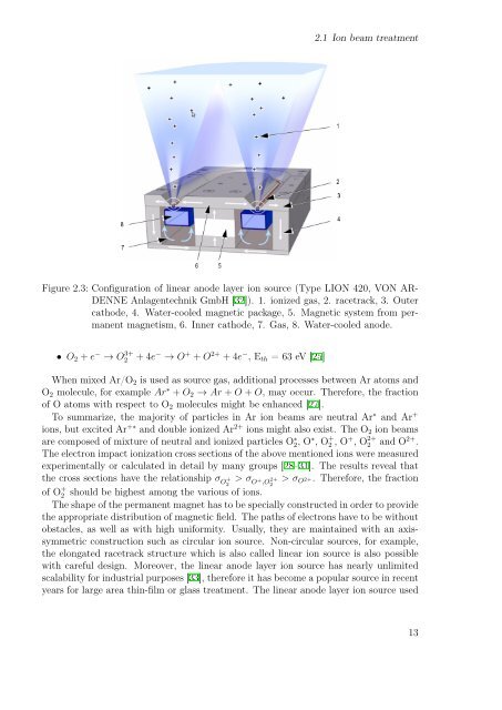
Figure 2.3: Configuration <strong>of</strong> l<strong>in</strong>ear anode layer ion source (Type LION 420, VON AR-<br />
DENNE Anlagentechnik GmbH [32]). 1. ionized gas, 2. racetrack, 3. Outer<br />
cathode, 4. Water-cooled magnetic package, 5. Magnetic system from permanent<br />
magnetism, 6. Inner cathode, 7. Gas, 8. Water-cooled anode.<br />
• O 2 + e − → O 3+<br />
2 + 4e − → O + + O 2+ + 4e − , E th = 63 eV [25]<br />
When mixed Ar/O 2 is used as source gas, additional processes between Ar atoms and<br />
O 2 molecule, for example Ar ∗ + O 2 → Ar + O + O, may occur. Therefore, the fraction<br />
<strong>of</strong> O atoms with respect to O 2 molecules might be enhanced [27].<br />
To summarize, the majority <strong>of</strong> particles <strong>in</strong> Ar ion beams are neutral Ar ∗ and Ar +<br />
ions, but excited Ar +∗ and double ionized Ar 2+ ions might also exist. The O 2 ion beams<br />
are composed <strong>of</strong> mixture <strong>of</strong> neutral and ionized particles O ∗ 2, O ∗ , O + 2 , O + , O 2+<br />
2 and O 2+ .<br />
The electron impact ionization cross sections <strong>of</strong> the above mentioned ions were measured<br />
experimentally or calculated <strong>in</strong> detail by many groups [28–31]. The results reveal that<br />
the cross sections have the relationship σ O<br />
+ > σ<br />
2 O + ,O 2+ > σ<br />
2 O 2+. Therefore, the fraction<br />
<strong>of</strong> O + 2 should be highest among the various <strong>of</strong> ions.<br />
The shape <strong>of</strong> the permanent magnet has to be specially constructed <strong>in</strong> order to provide<br />
the appropriate distribution <strong>of</strong> magnetic field. The paths <strong>of</strong> electrons have to be without<br />
obstacles, as well as with high uniformity. Usually, they are ma<strong>in</strong>ta<strong>in</strong>ed with an axissymmetric<br />
construction such as circular ion source. Non-circular sources, for example,<br />
the elongated racetrack structure which is also called l<strong>in</strong>ear ion source is also possible<br />
with careful design. Moreover, the l<strong>in</strong>ear anode layer ion source has nearly unlimited<br />
scalability for <strong>in</strong>dustrial purposes [33], therefore it has become a popular source <strong>in</strong> recent<br />
years for large area th<strong>in</strong>-film or glass treatment. The l<strong>in</strong>ear anode layer ion source used<br />
13