Ion Beam Treatment of Functional Layers in Thin-Film Silicon Solar ...
Ion Beam Treatment of Functional Layers in Thin-Film Silicon Solar ...
Ion Beam Treatment of Functional Layers in Thin-Film Silicon Solar ...

You also want an ePaper? Increase the reach of your titles
YUMPU automatically turns print PDFs into web optimized ePapers that Google loves.
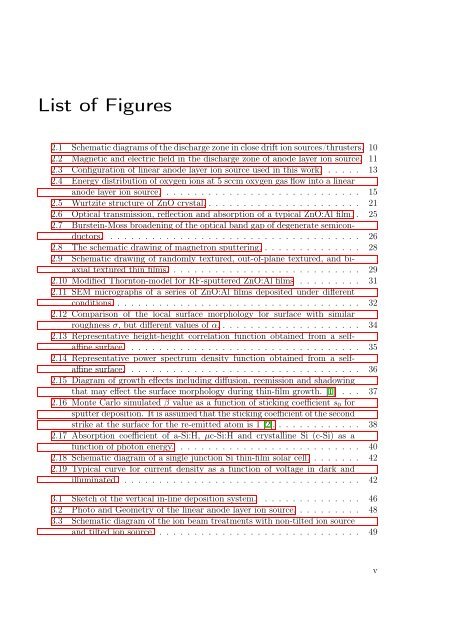
List <strong>of</strong> Figures<br />
2.1 Schematic diagrams <strong>of</strong> the discharge zone <strong>in</strong> close drift ion sources/thrusters. 10<br />
2.2 Magnetic and electric field <strong>in</strong> the discharge zone <strong>of</strong> anode layer ion source. 11<br />
2.3 Configuration <strong>of</strong> l<strong>in</strong>ear anode layer ion source used <strong>in</strong> this work. . . . . . 13<br />
2.4 Energy distribution <strong>of</strong> oxygen ions at 5 sccm oxygen gas flow <strong>in</strong>to a l<strong>in</strong>ear<br />
anode layer ion source. . . . . . . . . . . . . . . . . . . . . . . . . . . . . 15<br />
2.5 Wurtzite structure <strong>of</strong> ZnO crystal. . . . . . . . . . . . . . . . . . . . . . . 21<br />
2.6 Optical transmission, reflection and absorption <strong>of</strong> a typical ZnO:Al film. . 25<br />
2.7 Burste<strong>in</strong>-Moss broaden<strong>in</strong>g <strong>of</strong> the optical band gap <strong>of</strong> degenerate semiconductors.<br />
. . . . . . . . . . . . . . . . . . . . . . . . . . . . . . . . . . . . 26<br />
2.8 The schematic draw<strong>in</strong>g <strong>of</strong> magnetron sputter<strong>in</strong>g. . . . . . . . . . . . . . . 28<br />
2.9 Schematic draw<strong>in</strong>g <strong>of</strong> randomly textured, out-<strong>of</strong>-plane textured, and biaxial<br />
textured th<strong>in</strong> films. . . . . . . . . . . . . . . . . . . . . . . . . . . . 29<br />
2.10 Modified Thornton-model for RF-sputtered ZnO:Al films . . . . . . . . . 31<br />
2.11 SEM micrographs <strong>of</strong> a series <strong>of</strong> ZnO:Al films deposited under different<br />
conditions. . . . . . . . . . . . . . . . . . . . . . . . . . . . . . . . . . . . 32<br />
2.12 Comparison <strong>of</strong> the local surface morphology for surface with similar<br />
roughness σ, but different values <strong>of</strong> α. . . . . . . . . . . . . . . . . . . . . 34<br />
2.13 Representative height-height correlation function obta<strong>in</strong>ed from a selfaff<strong>in</strong>e<br />
surface. . . . . . . . . . . . . . . . . . . . . . . . . . . . . . . . . . 35<br />
2.14 Representative power spectrum density function obta<strong>in</strong>ed from a selfaff<strong>in</strong>e<br />
surface. . . . . . . . . . . . . . . . . . . . . . . . . . . . . . . . . . 36<br />
2.15 Diagram <strong>of</strong> growth effects <strong>in</strong>clud<strong>in</strong>g diffusion, reemission and shadow<strong>in</strong>g<br />
that may effect the surface morphology dur<strong>in</strong>g th<strong>in</strong>-film growth. [1] . . . 37<br />
2.16 Monte Carlo simulated β value as a function <strong>of</strong> stick<strong>in</strong>g coefficient s 0 for<br />
sputter deposition. It is assumed that the stick<strong>in</strong>g coefficient <strong>of</strong> the second<br />
strike at the surface for the re-emitted atom is 1 [2]. . . . . . . . . . . . . 38<br />
2.17 Absorption coefficient <strong>of</strong> a-Si:H, µc-Si:H and crystall<strong>in</strong>e Si (c-Si) as a<br />
function <strong>of</strong> photon energy. . . . . . . . . . . . . . . . . . . . . . . . . . . 40<br />
2.18 Schematic diagram <strong>of</strong> a s<strong>in</strong>gle junction Si th<strong>in</strong>-film solar cell. . . . . . . . 42<br />
2.19 Typical curve for current density as a function <strong>of</strong> voltage <strong>in</strong> dark and<br />
illum<strong>in</strong>ated. . . . . . . . . . . . . . . . . . . . . . . . . . . . . . . . . . . 42<br />
3.1 Sketch <strong>of</strong> the vertical <strong>in</strong>-l<strong>in</strong>e deposition system. . . . . . . . . . . . . . . 46<br />
3.2 Photo and Geometry <strong>of</strong> the l<strong>in</strong>ear anode layer ion source. . . . . . . . . . 48<br />
3.3 Schematic diagram <strong>of</strong> the ion beam treatments with non-tilted ion source<br />
and tilted ion source. . . . . . . . . . . . . . . . . . . . . . . . . . . . . . 49<br />
v