Modeling the Heat Gain of a Window With an Interior Shade ... - inive
Modeling the Heat Gain of a Window With an Interior Shade ... - inive
Modeling the Heat Gain of a Window With an Interior Shade ... - inive

Create successful ePaper yourself
Turn your PDF publications into a flip-book with our unique Google optimized e-Paper software.
Proceedings <strong>of</strong> Clima 2007 WellBeing Indoors<br />
<strong>Modeling</strong> <strong>the</strong> <strong>Heat</strong> <strong>Gain</strong> <strong>of</strong> a <strong>Window</strong> <strong>With</strong> <strong>an</strong> <strong>Interior</strong> <strong>Shade</strong>, How Much<br />
Energy Really Gets In?<br />
Douglas C. Hittle, Ph.D 1 <strong>an</strong>d Peter Simmonds, Ph.D 2<br />
¹ Colorado State University<br />
² IBE Inc., California<br />
Corresponding email: hittle@colostate.edu<br />
ABSTRACT<br />
Not long ago <strong>the</strong> ASHRAE Technical Committee on Load Calculation, TC 4.1, had a “bake <strong>of</strong>f’<br />
<strong>of</strong> sorts between different peak air-conditioning load calculation schemes <strong>an</strong>d programs. One <strong>of</strong><br />
<strong>the</strong> outcomes <strong>of</strong> this exercise was <strong>the</strong> realization that practitioners <strong>an</strong>d s<strong>of</strong>tware developers make<br />
largely different assumptions about how solar energy absorbed by window glass <strong>an</strong>d by window<br />
shades contributes to <strong>the</strong> room solar heat gain. For unshaded glass windows <strong>the</strong>re is general<br />
agreement [ASHRAE H<strong>an</strong>dbook <strong>of</strong> Fundamentals, 2005]. For a shade however, <strong>the</strong>re were two<br />
extremes in <strong>the</strong> models—one assumes that <strong>the</strong> shade rejects most <strong>of</strong> <strong>the</strong> solar energy that it does<br />
not tr<strong>an</strong>smit, logical if <strong>the</strong> shade is highly reflective <strong>an</strong>d <strong>the</strong> glass highly tr<strong>an</strong>smissive, <strong>the</strong> o<strong>the</strong>r<br />
assumes that all radiation absorbed by <strong>the</strong> shade is immediately convected into <strong>the</strong> room.<br />
Suffice it to say that we are not <strong>the</strong> first to derive <strong>an</strong>d present <strong>the</strong> fundamental equations <strong>of</strong> this<br />
heat tr<strong>an</strong>sfer problem. What we have done is to avoid <strong>an</strong>y simplifying assumptions in<br />
formulating <strong>the</strong> problem while allowing that some physical const<strong>an</strong>ts, convection coefficients in<br />
particular, are not well known <strong>an</strong>d need to be parameterized. We whet <strong>the</strong> readers’ appetite by<br />
revealing that for a glass/shade system where <strong>the</strong> glass was 22% tr<strong>an</strong>smissive <strong>an</strong>d <strong>the</strong> shade 52%<br />
tr<strong>an</strong>smissive, <strong>the</strong> total heat gain to <strong>the</strong> room from this window assembly was nearly half <strong>of</strong> <strong>the</strong><br />
incident radiation. Of course “It all depends!”<br />
INTRODUCTION<br />
Not long ago <strong>the</strong> ASHRAE Technical Committee on Load Calculation, TC 4.1, had a “bake <strong>of</strong>f’<br />
<strong>of</strong> sorts between different peak air-conditioning load calculation schemes <strong>an</strong>d programs. One <strong>of</strong><br />
<strong>the</strong> outcomes <strong>of</strong> this exercise was <strong>the</strong> realization that practitioners <strong>an</strong>d s<strong>of</strong>tware developers make<br />
largely different assumptions about how solar energy absorbed by window glass <strong>an</strong>d by window<br />
shades contributes to <strong>the</strong> room solar heat gain. For unshaded glass windows <strong>the</strong>re is general<br />
agreement [ASHRAE H<strong>an</strong>dbook <strong>of</strong> Fundamentals, 2005]. For a shade however, <strong>the</strong>re were two<br />
extremes in <strong>the</strong> models—one assumes that <strong>the</strong> shade rejects most <strong>of</strong> <strong>the</strong> solar energy that it does<br />
not tr<strong>an</strong>smit, logical if <strong>the</strong> shade is highly reflective <strong>an</strong>d <strong>the</strong> glass highly tr<strong>an</strong>smissive, <strong>the</strong> o<strong>the</strong>r<br />
assumes that all radiation absorbed by <strong>the</strong> shade is immediately convected into <strong>the</strong> room.<br />
Suffice it to say that we are not <strong>the</strong> first to derive <strong>an</strong>d present <strong>the</strong> fundamental equations <strong>of</strong> this<br />
heat tr<strong>an</strong>sfer problem (see [McCluney <strong>an</strong>d Mills, 1993, <strong>an</strong>d Duffie <strong>an</strong>d Beckm<strong>an</strong>, 1991]). What<br />
we have done is to avoid <strong>an</strong>y simplifying assumptions in formulating <strong>the</strong> problem while allowing<br />
that some physical const<strong>an</strong>ts, convection coefficients in particular, are not well known <strong>an</strong>d need<br />
to be parameterized. We whet <strong>the</strong> readers’ appetite by revealing that for a glass/shade system<br />
where <strong>the</strong> glass was 22% tr<strong>an</strong>smissive <strong>an</strong>d <strong>the</strong> shade 52% tr<strong>an</strong>smissive, <strong>the</strong> total heat gain to <strong>the</strong>
Proceedings <strong>of</strong> Clima 2007 WellBeing Indoors<br />
room from this window assembly was nearly half <strong>of</strong> <strong>the</strong> incident radiation. Of course “It all<br />
depends!”<br />
OBJECTIVE<br />
The objective <strong>of</strong> this study was to model <strong>the</strong> true solar heat gain <strong>of</strong> glass <strong>an</strong>d shade. Older, rough<br />
calculations have assumed that a 50% opaque shade will reduce <strong>the</strong> solar heat gain through <strong>the</strong><br />
glazing by something just less th<strong>an</strong> 50%. One <strong>of</strong> <strong>the</strong> less well understood parts <strong>of</strong> <strong>the</strong>se estimates<br />
is <strong>the</strong> energy convected from <strong>the</strong> glass <strong>an</strong>d shade into <strong>the</strong> room.<br />
The model developed under this study provides <strong>an</strong> accurate <strong>an</strong>d complete calculation scheme to<br />
support <strong>the</strong> perform<strong>an</strong>ce <strong>of</strong> a shade having various tr<strong>an</strong>smissivities <strong>an</strong>d absorptivities. The<br />
absorptivities are import<strong>an</strong>t for <strong>the</strong> calculation <strong>of</strong> solar interaction between <strong>the</strong> inside surface <strong>of</strong><br />
<strong>the</strong> glass <strong>an</strong>d shade <strong>an</strong>d to determine <strong>the</strong> temperature <strong>of</strong> <strong>the</strong> shade facing <strong>the</strong> occup<strong>an</strong>ts in a room.<br />
More import<strong>an</strong>tly, inside <strong>an</strong>d outside surface convection coefficients c<strong>an</strong> be varied to establish<br />
limits on how <strong>the</strong>y impact solar heat gain.<br />
BACKGROUND<br />
We know that if a porous shade is suspended between <strong>the</strong> inside surface <strong>of</strong> <strong>the</strong> glass <strong>an</strong>d <strong>the</strong><br />
adjoining room, <strong>the</strong> solar radiation will be reduced. However a detailed model is required to<br />
address several issues. These include: How much energy is reflected between <strong>the</strong> outer surface <strong>of</strong><br />
<strong>the</strong> shade <strong>an</strong>d <strong>the</strong> inner surface <strong>of</strong> <strong>the</strong> glass <strong>an</strong>d what happens to this energy? How much energy<br />
is re-radiated back into <strong>the</strong> room through <strong>the</strong> shade? How much energy is convected from <strong>the</strong><br />
glass <strong>an</strong>d shade into <strong>the</strong> room.<br />
THE MATHMATICAL CALCULATIONS<br />
The model developed permits <strong>the</strong> parametric evaluation <strong>of</strong> <strong>the</strong> window/shading characteristics<br />
including: The effect <strong>of</strong> different tr<strong>an</strong>smissivities <strong>of</strong> <strong>the</strong> shade. The surface temperature <strong>of</strong> <strong>the</strong><br />
glass with <strong>the</strong> shade in place. The surface temperature <strong>of</strong> <strong>the</strong> shade in <strong>the</strong> cavity. Convection<br />
coefficients, both inside <strong>an</strong>d outside.<br />
Note that in <strong>the</strong> model <strong>the</strong> effects <strong>of</strong> <strong>the</strong> sash <strong>an</strong>d frame have been excluded. However, ASHRAE<br />
St<strong>an</strong>dards 90.1 <strong>an</strong>d 90.2 <strong>an</strong>d national Energy Codes require that fenestration ratings be<br />
determined in accord<strong>an</strong>ce with NFRC (National Fenestration Rating Council) procedures. These<br />
procedures (NFRC 200 for solar heat gain coefficient) explicitly rate <strong>the</strong> entire fenestration<br />
product including <strong>the</strong> frame, sash, <strong>an</strong>d glass. See <strong>the</strong> NFRC website at www.nfrc.org for fur<strong>the</strong>r<br />
information.<br />
<strong>Modeling</strong> Incident solar radiation (this section is presented for <strong>the</strong> sake <strong>of</strong> completeness)<br />
The solar const<strong>an</strong>t, G sc , is <strong>the</strong> energy from <strong>the</strong> sun, per unit time, received on a unit area <strong>of</strong><br />
surface perpendicular to <strong>the</strong> direction <strong>of</strong> propagation <strong>of</strong> <strong>the</strong> radiation, at me<strong>an</strong> earth-sun dist<strong>an</strong>ce,<br />
outside <strong>of</strong> <strong>the</strong> atmosphere. Measurements <strong>of</strong> <strong>the</strong> const<strong>an</strong>t were made with high altitude aircraft<br />
flights, balloons, <strong>an</strong>d spacecraft [Thekaedara et.al. 1971 <strong>an</strong>d 1976]. Later, spacecraft <strong>an</strong>d rocket<br />
flight data were reported [see Hickey et.al, Wilson et.al., <strong>an</strong>d Dunc<strong>an</strong> et al.] <strong>an</strong>d led to <strong>the</strong><br />
adoption <strong>of</strong> <strong>the</strong> value <strong>of</strong> 1367 W/m 2 for <strong>the</strong> solar const<strong>an</strong>t by <strong>the</strong> World Radiation Center. We<br />
will use this value to calculate <strong>the</strong> beam, diffuse <strong>an</strong>d reflected radiation on <strong>the</strong> exterior <strong>of</strong> a<br />
window.
Proceedings <strong>of</strong> Clima 2007 WellBeing Indoors<br />
The dist<strong>an</strong>ce from <strong>the</strong> earth to <strong>the</strong> sun varies with time <strong>of</strong> year. Hence <strong>the</strong> extraterrestrial<br />
radiation, G on , measured on <strong>the</strong> pl<strong>an</strong>e normal to <strong>the</strong> radiation on <strong>the</strong> nth day <strong>of</strong> <strong>the</strong> year is given<br />
by:<br />
360n<br />
Gon = Gsc (1 + 0.033cos ) Eq.[1]<br />
365<br />
Clear sky radiation on <strong>the</strong> earth’s surface c<strong>an</strong> be estimated by calculating <strong>the</strong> atmospheric<br />
tr<strong>an</strong>smitt<strong>an</strong>ce for beam radiation, τ batmos, from a method presented by Hottel [Hottel, 1976]. <br />
τ<br />
batmos<br />
= a + a exp( −k<br />
/ cosθ<br />
) Eq[2]<br />
o<br />
1 z<br />
θ z = solar zenith <strong>an</strong>gle, a o =0.3887, a 1 =0.5496, k =0.3176, (for mid-latitude winter)<br />
Liu <strong>an</strong>d Jord<strong>an</strong>, 1960 formulated <strong>an</strong> empirical relationship for diffuse radiation for clear days:<br />
τ<br />
datmos<br />
=<br />
Gd<br />
= 0.271−<br />
0. 294τ<br />
b<br />
Eq[3]<br />
Go<br />
where G o =G on (cos(Θ z )).<br />
As <strong>an</strong> example, for a clear day on December 21 st in Los Angeles 1 , <strong>the</strong> above formulations yield:<br />
τ batmoa =0.6938 –atmospheric tr<strong>an</strong>smitt<strong>an</strong>ce beam radiation, τ datmos =0.0670 –atmospheric<br />
tr<strong>an</strong>smitt<strong>an</strong>ce diffuse radiation, G on =1411 W/m 2 –extraterrestrial normal beam radiation,<br />
G cnb =979.3 W/m 2 –normal beam radiation at <strong>the</strong> earth’s surface, G o =761.5 W/m 2 --<br />
extraterrestrial beam radiation on a horizontal pl<strong>an</strong>e, G cd =94.59 W/m 2 –diffuse radiation at <strong>the</strong><br />
earth’s surface.<br />
Beam <strong>an</strong>d Diffuse Radiation Tr<strong>an</strong>smitted <strong>an</strong>d Absorbed<br />
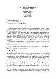
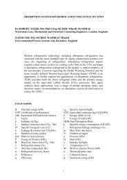
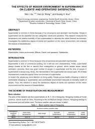
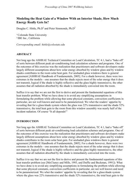
Figure 1 shows a schematic <strong>of</strong> <strong>the</strong> glass <strong>an</strong>d porous shade system. The arrows are a symbolic<br />
representation <strong>of</strong> <strong>the</strong> short wave energy, accounting for radiation, tr<strong>an</strong>smitted, reflected, <strong>an</strong>d<br />
absorbed. The diagram is for beam radiation but a similar accounting applies to diffuse radiation.<br />
“Abs” denotes <strong>the</strong> fraction <strong>of</strong> absorbed short wave energy for <strong>the</strong> glass or shade on each<br />
successive reflection. The portion <strong>of</strong> <strong>the</strong> incident beam short wave energy that is ultimately<br />
absorbed by <strong>the</strong> shade, Abs bss , is:<br />
Absbss<br />
∞<br />
n<br />
τgbαss<br />
= τgbαss<br />
∑ [ ρssρgd<br />
] =<br />
Eq[4]<br />
n = 0<br />
1− ρssρgd<br />
τ gb =short wave tr<strong>an</strong>smitt<strong>an</strong>ce <strong>of</strong> <strong>the</strong> glass (a function <strong>of</strong> incidence <strong>an</strong>gle, θ), α ss =short wave<br />
absorpt<strong>an</strong>ce <strong>of</strong> <strong>the</strong> shade, ρ gd =diffuse reflect<strong>an</strong>ce <strong>of</strong> <strong>the</strong> glass 2<br />
1 We use this example location <strong>an</strong>d date throughout <strong>the</strong> paper a representing a hot winter climate when south sun<br />
will be at a maximum. Also, accounting for cloudy wea<strong>the</strong>r is possible using <strong>the</strong> model provided but since <strong>the</strong> paper<br />
is motivated by <strong>an</strong>d concerned with peak load calculation we have not considered cloudy days in our example.<br />
2 Br<strong>an</strong>demuehl <strong>an</strong>d Beckm<strong>an</strong> have shown that <strong>the</strong> effective incidence <strong>an</strong>gle for isotropic diffuse radiation is<br />
approximately 60 degrees. [Br<strong>an</strong>demuehl <strong>an</strong>d Beckm<strong>an</strong>, 1980]. integration performed using m<strong>an</strong>ufacturer’s data<br />
shown in <strong>the</strong> next section produced results that agree to within 1% <strong>of</strong> <strong>the</strong> Br<strong>an</strong>demuehl/Beckm<strong>an</strong> results.
Proceedings <strong>of</strong> Clima 2007 WellBeing Indoors<br />
The incident radiation on <strong>the</strong> inside <strong>of</strong> <strong>the</strong> glass is diffuse radiation reflected from <strong>the</strong> shade.<br />
Optical properties for diffuse radiation for <strong>the</strong> glass c<strong>an</strong> be determined for isotropic radiation by<br />
integration over all <strong>an</strong>gles <strong>of</strong> incidence. This was done using glass properties from a<br />
m<strong>an</strong>ufacturer <strong>an</strong>d shown in <strong>the</strong> next section <strong>of</strong> this report.<br />
Similarly, <strong>the</strong> short wave beam radiation fraction absorbed by <strong>the</strong> glass, Abs bg , is:<br />
Abs bg<br />
∞<br />
n 1 n<br />
τ gb α gd ρss<br />
= α gb + τ gb α gd ∑ [ ρ<br />
+<br />
ss ρ gd ] = α gb +<br />
Eq[5]<br />
n = 0<br />
1 − ρ ss ρ gd<br />
where variables are as defined before <strong>an</strong>d α gb = beam absorpt<strong>an</strong>ce <strong>of</strong> <strong>the</strong> glass (a function <strong>of</strong><br />
incidence <strong>an</strong>gle, θ), α gd = diffuse absorpt<strong>an</strong>ce <strong>of</strong> glass. Equations 4 <strong>an</strong>d 5 also apply for diffuse<br />
radiation Abs dss <strong>an</strong>d Abs dg , but τ gb is replaced with τ gd <strong>an</strong>d α gb is replaced with α gd (see footnote<br />
7).<br />
Glass<br />
<strong>Shade</strong><br />
P τ gb ρ ss 2 ρ gd<br />
2<br />
Abs=ρ ss 2 τ gs ρ gd 2 α ss<br />
τ gb ρ ss<br />
2<br />
ρ gd τ gd ρ ss<br />
2<br />
τ gb ρ gd<br />
2<br />
Abs= ρ ss 2 τ gb ρ g60 α g60<br />
ρ ss<br />
2<br />
τ gb ρ gd<br />
P τ sb ρ ss ρ gd<br />
Abs=ρ ss τ gb ρ gδ α ss<br />
τ gb ρ ss τ gd<br />
ρ ss τ gb ρ gd<br />
Abs= ρ ss τ gb α gd<br />
ρ ss τ gb<br />
P τ gb<br />
Abs=τ gb α ss<br />
ρ gb<br />
τ gb<br />
Abs=α gb<br />
Figure 1. Short wave energy flows.<br />
We c<strong>an</strong> now do a short wave energy bal<strong>an</strong>ce:<br />
[ cos θAbs<br />
G cd Abs ]<br />
& 3<br />
Q gs = G cnb bg +<br />
dg<br />
Eq[6]<br />
& = [ cos θ Abs<br />
Abs ] Eq[7]<br />
Q ss G cnb<br />
bss + G cd<br />
3 We assume a uniform diffuse short wave field. This is accurate except for <strong>the</strong> lower floors where <strong>the</strong> diffuse<br />
radiation is a mix <strong>of</strong> diffuse sky radiation <strong>an</strong>d ground reflected radiation. We have ignored ground reflected<br />
radiation in this <strong>an</strong>alysis but its inclusion would be straight forward.<br />
dss
Proceedings <strong>of</strong> Clima 2007 WellBeing Indoors<br />
P = porosity or open fraction <strong>of</strong> <strong>the</strong> shade (this is <strong>the</strong> tr<strong>an</strong>smitt<strong>an</strong>ce <strong>of</strong> <strong>the</strong> shade), Q &<br />
gs<br />
<strong>an</strong>d Q&<br />
ss<br />
are<br />
<strong>the</strong> short wave radiation absorbed by <strong>the</strong> glass <strong>an</strong>d shade respectively. Some <strong>of</strong> <strong>the</strong> radiation<br />
reflected from <strong>the</strong> shade is reflected again by <strong>the</strong> glass <strong>an</strong>d <strong>the</strong>n tr<strong>an</strong>smitted through <strong>the</strong> shade to<br />
<strong>the</strong> room. Referring to Figure 3 <strong>the</strong> qu<strong>an</strong>tity is:<br />
⎡ (P * τgs ⎤ ⎡ (P * τgs ⎤<br />
Q & = θ<br />
)<br />
⎢<br />
τ ⎥ +<br />
)<br />
refin G cnb cos<br />
- P * gs G cd ⎢<br />
- P * τgs⎥<br />
⎣(1-<br />
ρss<br />
* ρsd ) ⎦ ⎣(1-<br />
ρss<br />
* ρsd )<br />
Eq[8]<br />
⎦<br />
Glass Properties<br />
Data has been obtained for a heat absorbing glass. This product represents <strong>an</strong> application where<br />
total heat gain might be signific<strong>an</strong>tly higher th<strong>an</strong> intuition may suggest because its tr<strong>an</strong>smissivity<br />
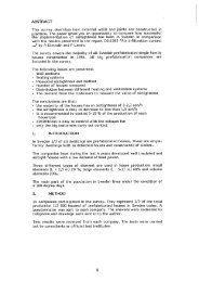
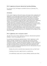
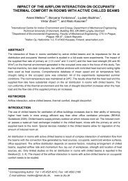
is so low. We will begin our <strong>an</strong>alysis with this product but will move on to o<strong>the</strong>rs. Figure 2<br />
shows <strong>the</strong> tr<strong>an</strong>smitt<strong>an</strong>ce, absorpt<strong>an</strong>ce, <strong>an</strong>d reflect<strong>an</strong>ce for <strong>the</strong> glass as a function <strong>of</strong> incident<br />
<strong>an</strong>gle. In general, <strong>the</strong>se properties c<strong>an</strong> be characterized as functions <strong>of</strong> <strong>the</strong> cosine <strong>of</strong> <strong>the</strong> incidence<br />
<strong>an</strong>gle, Θ. An incidence <strong>an</strong>gle modifier c<strong>an</strong> be defined as <strong>the</strong> ratio <strong>of</strong> <strong>the</strong> property at <strong>an</strong>gle <strong>of</strong><br />
incidence Θ to <strong>the</strong> property at normal incidence. 4 For example:<br />
K tr<strong>an</strong>smitt<strong>an</strong>ce<br />
= Eq[9]<br />
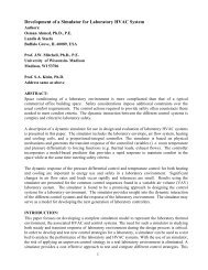
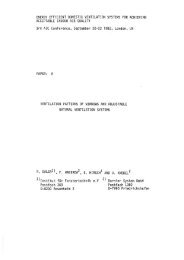
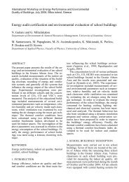
Plots <strong>of</strong> incidence <strong>an</strong>gle modifiers for tr<strong>an</strong>smitt<strong>an</strong>ce, absorpt<strong>an</strong>ce, <strong>an</strong>d reflect<strong>an</strong>ce versus<br />
1<br />
−1<br />
are shown in Figure 3. Curve fits are shown for tr<strong>an</strong>smitt<strong>an</strong>ce <strong>an</strong>d reflect<strong>an</strong>ce – <strong>the</strong><br />
cos( θ)<br />
fits are generally excellent. The equations for <strong>the</strong> trend lines c<strong>an</strong> be used to calculate<br />
tr<strong>an</strong>smitt<strong>an</strong>ce <strong>an</strong>d reflect<strong>an</strong>ce for <strong>an</strong>y <strong>an</strong>gle Θ less th<strong>an</strong> 80 degrees <strong>an</strong>d, since τ+α+ρ=1, <strong>the</strong><br />
absorpt<strong>an</strong>ce c<strong>an</strong> be calculated. For a winter design day at noon in Los Angeles, Θ is 22.6<br />
degrees.<br />
τ τ θ<br />
n<br />
4 The incidence <strong>an</strong>gle modifier (IAM) has its roots in <strong>the</strong> experimental characterization <strong>of</strong> solar collectors. The<br />
definition used here is a slight modification <strong>of</strong> <strong>the</strong> IAM used with solar collectors.
Proceedings <strong>of</strong> Clima 2007 WellBeing Indoors<br />
Solar Tr<strong>an</strong>smitt<strong>an</strong>ce, Absorpt<strong>an</strong>ce, Reflect<strong>an</strong>ce vs Theta<br />
120<br />
Tr<strong>an</strong>smitt<strong>an</strong>ce, Reflect<strong>an</strong>ce, Absorpt<strong>an</strong>ce, percent<br />
100<br />
80<br />
60<br />
40<br />
20<br />
Tr<strong>an</strong>smitt<strong>an</strong>ce<br />
Reflect<strong>an</strong>ce<br />
Absorpt<strong>an</strong>ce<br />
0<br />
0 10 20 30 40 50 60 70 80 90 100<br />
θ degrees<br />
Figure 2. Optical properties <strong>of</strong> heat absorbing glass.<br />
2.5<br />
2<br />
Ktr<strong>an</strong>smitt<strong>an</strong>ce<br />
Kreflect<strong>an</strong>ce<br />
Kabsorpt<strong>an</strong>ce<br />
Linear (Ktr<strong>an</strong>smitt<strong>an</strong>ce)<br />
Poly. (Kreflect<strong>an</strong>ce)<br />
y = 0.1825x 2 + 0.2728x + 0.9845<br />
R 2 = 0.9986<br />
Incidence Angle Modifier<br />
1.5<br />
1<br />
0.5<br />
y = -0.2054x + 0.9945<br />
R 2 = 0.9918<br />
0<br />
0 0.2 0.4 0.6 0.8 1 1.2 1.4 1.6 1.8 2<br />
(1/cos(θ)) - 1<br />
Figure 3. Incidence <strong>an</strong>gle modifiers versus (1/cos(θ)) – 1)
Proceedings <strong>of</strong> Clima 2007 WellBeing Indoors<br />
Long Wave Radiation Exch<strong>an</strong>ge<br />
The long wave radiation exch<strong>an</strong>ge between <strong>the</strong> glass <strong>an</strong>d <strong>the</strong> shade c<strong>an</strong> be characterized by<br />
treating <strong>the</strong> problem as one <strong>of</strong> gray body radiation exch<strong>an</strong>ge with essentially <strong>the</strong> same geometric<br />
interpretation as for short wave radiation. The interior is assumed to behave like a cavity <strong>an</strong>d<br />
hence a black body. The long wave radiation heat exch<strong>an</strong>ge between <strong>the</strong> glass <strong>an</strong>d shade c<strong>an</strong> <strong>the</strong>n<br />
be written as:<br />
ε ( )<br />
4 4<br />
ssl 1−<br />
P εglσ(T g − T s )<br />
Q& W / m<br />
2<br />
glsl =<br />
into <strong>the</strong> mesh<br />
1−<br />
(1 − εgl )(1 − P)(1 − εssl )<br />
Eq[10]<br />
where σ =Boltzm<strong>an</strong> const<strong>an</strong>t = 5.670E-08 W/m 2 -K 4 <strong>an</strong>d T g <strong>an</strong>d T s are <strong>the</strong> glass <strong>an</strong>d shade<br />
temperatures in degrees Kelvin. Note that <strong>the</strong> conductivity <strong>of</strong> <strong>the</strong> glass <strong>an</strong>d shade are sufficiently<br />
high that <strong>the</strong>ir temperatures c<strong>an</strong> be assumed to be locally uniform. Similarly,<br />
Q &<br />
s lg l<br />
= − & W / m<br />
2<br />
Qglsl into <strong>the</strong> glass<br />
Eq[11]<br />
The long wave radiation from <strong>the</strong> interior to <strong>the</strong> glass is:<br />
Pσ(T<br />
4 4<br />
i<br />
− T g )<br />
Q& W / m<br />
2<br />
igl =<br />
into <strong>the</strong> glass<br />
1−<br />
(1 − εgl )(1 − P)(1 − εsl )<br />
Eq[12]<br />
The glass also exch<strong>an</strong>ges long wave radiation with <strong>the</strong> outdoors. Assuming that all <strong>the</strong><br />
surroundings are at <strong>the</strong> outdoor temperature, <strong>the</strong> long wave radiation received by <strong>the</strong> glass from<br />
<strong>the</strong> outdoor environment is:<br />
Q & (T<br />
4<br />
T<br />
4<br />
ogl = εglσ<br />
o − g )<br />
Eq[13]<br />
Similarly, <strong>the</strong> radiation from <strong>the</strong> interior to <strong>the</strong> shade c<strong>an</strong> be written as:<br />
P(1 − ε<br />
4 4<br />
gl )(1 − P) εslσ(T<br />
i<br />
− T g )<br />
Q& (1 P) (T<br />
4<br />
T<br />
4<br />
isl =<br />
sl i s )<br />
1 (1 gl )(1 P)(1 sl ) + − ε σ −<br />
Eq[14]<br />
− − ε − − ε<br />
Hence <strong>the</strong> total incoming long wave radiation for <strong>the</strong> glass is:<br />
Q &<br />
gl = Q&<br />
ogl + Q&<br />
s lg l + Q&<br />
igl<br />
Eq[15]<br />
<strong>an</strong>d for <strong>the</strong> shade:<br />
Q &<br />
sl = & & Qglsl + Qisl<br />
Eq[16]<br />
Convection<br />
<strong>Heat</strong> is tr<strong>an</strong>sferred from or to <strong>the</strong> glass <strong>an</strong>d shade by convection to <strong>the</strong> interior air <strong>an</strong>d outdoor<br />
air. For <strong>the</strong> glass, heat flow in by convection is:<br />
Q &<br />
gc = hi *(Ti - Tg) + ho *(To -Tg)<br />
Eq[17]
Proceedings <strong>of</strong> Clima 2007 WellBeing Indoors<br />
where h i =interior convective heat tr<strong>an</strong>sfer coefficient W/m 2 -K (5 was used initially) 5 , h o =exterior<br />
convective heat tr<strong>an</strong>sfer coefficient W/m 2 -K (15 was used initially). For <strong>the</strong> shade:<br />
Q &<br />
sc = hi2(1- P)(Ti - Ts)<br />
Eq[18]<br />
Total <strong>Heat</strong> Bal<strong>an</strong>ce<br />
We now note that <strong>the</strong> heat flows for long <strong>an</strong>d short wave radiation <strong>an</strong>d for convection have been<br />
defined as being into <strong>the</strong> glass <strong>an</strong>d shade. Since <strong>the</strong> sum <strong>of</strong> <strong>the</strong> energy into <strong>the</strong> glass <strong>an</strong>d into <strong>the</strong><br />
shade has to be zero in steady state, some flows will have a negative sign indicating that <strong>the</strong> heat<br />
flow is out <strong>of</strong> <strong>the</strong> material. The overall gr<strong>an</strong>d total heat bal<strong>an</strong>ce for <strong>the</strong> glass is:<br />
For <strong>the</strong> shade:<br />
Q &<br />
g = & Qgs + & Qgl + & Qgc = 0<br />
Eq[19]<br />
Q &<br />
s = Q&<br />
ss + Q&<br />
sl + Q&<br />
sc = 0<br />
Eq[20]<br />
(As a reminder, all flows <strong>an</strong>d heat bal<strong>an</strong>ces are based on a unit area <strong>of</strong> <strong>the</strong> exterior façade, i.e.<br />
one square meter <strong>of</strong> glass adjacent to one square meter <strong>of</strong> shade)<br />
The total radi<strong>an</strong>t heat flow tr<strong>an</strong>smitted <strong>an</strong>d reradiated into <strong>the</strong> room is:<br />
Q & gainrad = − & Qisl − & Qigl + P(Gcnb cos( θ)<br />
τgs<br />
+ Gcdτgd) + & Qrefin Eq[21]<br />
The total heat flow into <strong>the</strong> room caused by radiation <strong>an</strong>d convection from/to <strong>the</strong> glass <strong>an</strong>d shade<br />
is:<br />
Q &<br />
ga int ot<br />
= Q&<br />
gainrad − h i (T i - T g ) − Q&<br />
sc<br />
Eq[22]<br />
Engineering Equation Solver<br />
The model, as defined by <strong>the</strong> above equations, was implemented in Engineering Equation Solver<br />
(EES), a tool for solving simult<strong>an</strong>eous equations, especially those involving solar energy<br />
relations <strong>an</strong>d <strong>the</strong>rmodynamic properties [Engineering Equation Solver, 2005].<br />
GENERAL RESULTS<br />
The results are from a simulation <strong>of</strong> a south facing room on a hot winter day in Los Angeles<br />
(outside temperature 35 o C, 95 o F). This illustrates how <strong>the</strong> model c<strong>an</strong> be used. The glass in this<br />
example was assumed to be oriented vertically <strong>an</strong>d facing due south. However, <strong>an</strong>y tilt or<br />
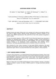
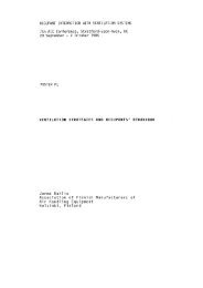
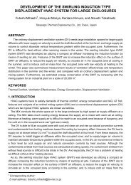
azimuth <strong>an</strong>gle c<strong>an</strong> be explored using <strong>the</strong> EES model. Energy flows for <strong>the</strong> glass/shade ensemble<br />
were enumerated for this day <strong>an</strong>d are shown in Figure 4 below.<br />
The figure shows that about 45% <strong>of</strong> <strong>the</strong> incident radiation becomes a heat gain to <strong>the</strong> room. This<br />
occurs even though <strong>the</strong> tr<strong>an</strong>smitt<strong>an</strong>ce <strong>of</strong> <strong>the</strong> glass is about 0.22 <strong>an</strong>d <strong>the</strong> tr<strong>an</strong>smitt<strong>an</strong>ce <strong>of</strong> <strong>the</strong> shade<br />
is 0.53. The long wave radiation <strong>an</strong>d energy convected into <strong>the</strong> room from <strong>the</strong> glass <strong>an</strong>d shade<br />
contribute signific<strong>an</strong>tly to <strong>the</strong> heat gain (in addition to what is tr<strong>an</strong>smitted directly). Multiple<br />
reflections between <strong>the</strong> shade <strong>an</strong>d glass, sometimes not considered in simple models, also impact<br />
heat gain, both directly <strong>an</strong>d as <strong>the</strong>y affect <strong>the</strong> surface temperatures <strong>of</strong> <strong>the</strong> glass <strong>an</strong>d shade.<br />
5 Convection coefficients from <strong>the</strong> ASHRAE H<strong>an</strong>dbook <strong>of</strong> Fundamentals were used as starting points but <strong>the</strong><br />
ASHRAE values are higher th<strong>an</strong> those used because <strong>the</strong>y include equivalent radi<strong>an</strong>t tr<strong>an</strong>sfer, which is h<strong>an</strong>dled<br />
explicitly in this model. See ASHRAE H<strong>an</strong>dbook <strong>of</strong> Fundamentals. Even taking this into account both <strong>the</strong>se<br />
coefficients may be high <strong>an</strong>d we will return to this issue later.
Proceedings <strong>of</strong> Clima 2007 WellBeing Indoors<br />
This study also evaluated <strong>the</strong> affects <strong>of</strong> shade “porosity,” <strong>the</strong> fraction <strong>of</strong> open area <strong>of</strong> <strong>the</strong> shade or<br />
its tr<strong>an</strong>smissivity. Their impact was evaluated using parametric tables. Figure 5 shows <strong>the</strong><br />
variation <strong>of</strong> glass <strong>an</strong>d shade temperature with variation <strong>of</strong> porosity. For <strong>the</strong> shade, more energy is<br />
absorbed with decreasing porosity but <strong>the</strong>re is a simult<strong>an</strong>eous increase in energy convected <strong>of</strong>f <strong>of</strong><br />
<strong>the</strong> shade due to <strong>the</strong> increased surface area <strong>of</strong> <strong>the</strong> shade material. The glass, on <strong>the</strong> o<strong>the</strong>r h<strong>an</strong>d,<br />
receives more reflected radiation from <strong>the</strong> shade at low porosity causing a very slight increase in<br />
glass temperature. However, <strong>the</strong> glass temperature is most strongly influenced by its high<br />
absorpt<strong>an</strong>ce in <strong>the</strong> solar spectrum.<br />
Figure 6 shows <strong>the</strong> total heat gain to <strong>the</strong> room <strong>an</strong>d <strong>the</strong> radi<strong>an</strong>t heat gain versus shade porosity.<br />
The relationship is very nearly a straight line r<strong>an</strong>ging from about 415 to 520 W/m 2 (130 Btu/hrft<br />
2 to 166 Btu/hr-ft 2 ). At <strong>the</strong> lower end, heat tr<strong>an</strong>sfer to <strong>the</strong> room is dominated by convection<br />
from <strong>the</strong> glass <strong>an</strong>d shade <strong>an</strong>d by long wave radiation tr<strong>an</strong>sfer. At <strong>the</strong> upper end, direct solar gain<br />
plays a more import<strong>an</strong>t role. Long wave radiation from <strong>the</strong> glass to <strong>the</strong> room also increases as <strong>the</strong><br />
glass “sees” more <strong>of</strong> <strong>the</strong> room <strong>an</strong>d less <strong>of</strong> <strong>the</strong> shade. The glass absorbs a large fraction <strong>of</strong> <strong>the</strong><br />
incoming radiation <strong>an</strong>d hence is hot, causing long wave radiation to go into <strong>the</strong> room <strong>an</strong>d<br />
promoting convective tr<strong>an</strong>sfer from <strong>the</strong> glass to <strong>the</strong> room.<br />
Some observations are in order. First it is import<strong>an</strong>t to say that <strong>the</strong> heat absorbing glass used in<br />
our model represents a ra<strong>the</strong>r extreme case – it really is a solar collector. That said, we note from<br />
figure 4 that 45% <strong>of</strong> <strong>the</strong> heat gain to <strong>the</strong> room is convected from <strong>the</strong> glass <strong>an</strong>d shade. Fur<strong>the</strong>r<br />
more, we used table 22 <strong>of</strong> chapter 31 <strong>of</strong> <strong>the</strong> 2005 ASHRAE H<strong>an</strong>dbook <strong>of</strong> Fundamentals to find<br />
<strong>the</strong> solar heat gain coefficient <strong>an</strong>d <strong>the</strong> interior attenuation coefficient <strong>an</strong>d to calculate <strong>the</strong> fraction<br />
<strong>of</strong> incident radiation that would become heat gain. For a shade tr<strong>an</strong>smissivity <strong>of</strong> 0.2 <strong>the</strong> result<br />
was 0.29. The model described above predicts 0.43.
Proceedings <strong>of</strong> Clima 2007 WellBeing Indoors<br />
Figure 4. Energy flows occurring in <strong>the</strong> glass/shade system.
Proceedings <strong>of</strong> Clima 2007 WellBeing Indoors<br />
60<br />
135<br />
130<br />
55<br />
T glass, F<br />
125<br />
Temperature, C<br />
50<br />
45<br />
T glass, C<br />
T shade, F<br />
120<br />
115<br />
110<br />
105<br />
100<br />
Temper ature, F<br />
95<br />
40<br />
T shade, C<br />
90<br />
85<br />
35<br />
80<br />
0.1 0.2 0.3 0.4 0.5 0.6 0.7 0.8 0.9<br />
P<br />
Figure 5. Glass <strong>an</strong>d shade temperature versus shade porosity (tr<strong>an</strong>smitt<strong>an</strong>ce).<br />
550<br />
200<br />
<strong>Heat</strong> <strong>Gain</strong>, W/m 2<br />
500<br />
450<br />
400<br />
350<br />
300<br />
250<br />
Total <strong>Heat</strong> <strong>Gain</strong><br />
Total <strong>Heat</strong> <strong>Gain</strong><br />
Radi<strong>an</strong>t <strong>Heat</strong> <strong>Gain</strong><br />
180<br />
160<br />
140<br />
120<br />
100<br />
80<br />
<strong>Heat</strong> <strong>Gain</strong>, Btu/hr-ft 2<br />
200<br />
60<br />
150<br />
Radi<strong>an</strong>t <strong>Heat</strong> <strong>Gain</strong><br />
40<br />
100<br />
20<br />
0.1 0.2 0.3 0.4 0.5 0.6 0.7 0.8 0.9<br />
P<br />
Figure 6. Total heat gain through façade versus shade porosity (tr<strong>an</strong>smitt<strong>an</strong>ce).<br />
Convection coefficients<br />
We next explore <strong>the</strong> impact <strong>of</strong> convection coefficients on total solar heat gain. As a reminder, <strong>the</strong><br />
properties <strong>of</strong> <strong>the</strong> glass <strong>an</strong>d shade are:<br />
Glass<br />
<strong>Shade</strong><br />
Tr<strong>an</strong>smissivity 0.23 0.53<br />
Reflectivity 0.11 0.22<br />
Absorptivity 0.66 0.25
Proceedings <strong>of</strong> Clima 2007 WellBeing Indoors<br />
We deal first with <strong>the</strong> outside convection coefficient. Yazd<strong>an</strong>i<strong>an</strong> <strong>an</strong>d Klems [1994] measured <strong>the</strong><br />
convection coefficient on <strong>the</strong>ir test facility for a first floor window <strong>an</strong>d determined that it varied<br />
from 2-20 W/m 2 -K over 0-10 m/s (0-45 miles per hour). Keeping 5 W/m 2 -K for <strong>the</strong> inside<br />
convection coefficient, <strong>the</strong> variation in heat gain due to variation in outside convection<br />
coefficient c<strong>an</strong> be calculated <strong>an</strong>d is shown in figure 7.<br />
620<br />
200<br />
600<br />
190<br />
Q gaintot [W/m 2 ]<br />
580<br />
560<br />
540<br />
520<br />
500<br />
480<br />
SI<br />
IP<br />
180<br />
170<br />
160<br />
150<br />
Q gaintotIP [Btu/hr-ft 2 ]<br />
460<br />
140<br />
2 4 6 8 10 12 14 16 18 20<br />
h o [W/m 2 K]<br />
Figure 6. <strong>Heat</strong> gain versus outside convection coefficient.<br />
How does figure 7 illuminate us. Firstly, we are reminded that <strong>the</strong> model we have developed is<br />
for total heat gain through a glass/shade system. In <strong>the</strong> dark, at night, <strong>the</strong>re would be heat gain<br />
from a hot outdoors to a cool room <strong>an</strong>d a low convection coefficient would reduce <strong>the</strong> heat gain.<br />
However, when <strong>the</strong> glass is hotter th<strong>an</strong> <strong>the</strong> surroundings, wind (<strong>an</strong>d a high outside convection<br />
coefficient) helps reduce <strong>the</strong> heat gain to <strong>the</strong> room even when it is hot outdoors <strong>an</strong>d cool indoors.<br />
In this example with heat absorbing glass, <strong>the</strong> worst case scenario is not when <strong>the</strong> exterior film<br />
coefficient is high (i. e. a high speed wind) but when <strong>the</strong> air outside <strong>the</strong> glass is still. Methods<br />
that try to separate conduction/convective heat gain due to temperature difference through a<br />
window from solar heat gain seemed doomed or at least impractical. Ditto for schemes that try to<br />
combine convection <strong>an</strong>d radiation at <strong>the</strong> inside or outside surface.<br />
Figure 7 shows that heat gain to a room caused by <strong>the</strong> sun c<strong>an</strong> vary by 50% depending on how<br />
much energy absorbed by <strong>the</strong> glass is swept to <strong>the</strong> outdoors. How about convection <strong>of</strong>f <strong>the</strong> inside<br />
<strong>of</strong> <strong>the</strong> glass <strong>an</strong>d shade? Fisher <strong>an</strong>d Pederson [1995] <strong>an</strong>d Spitler in referenced work show that <strong>the</strong><br />
inside convection coefficient <strong>of</strong>f interior walls r<strong>an</strong>ges between 2 <strong>an</strong>d 5 W/m 2 -K. If, for <strong>the</strong> sake<br />
<strong>of</strong> consistency, we assume that <strong>the</strong> outside convection coefficient is 15 W/m 2 -K, what happens<br />
when we vary <strong>the</strong> inside coefficient? Figure 8 below shows <strong>the</strong> result.We varied <strong>the</strong> inside<br />
coefficient from 2 to 10 W/m 2 -K because <strong>the</strong> glass <strong>an</strong>d shade could be hotter th<strong>an</strong> o<strong>the</strong>r room<br />
surfaces, promoting convection. The variation is 45%.<br />
We now compare heat absorbing glass with 1/8 inch clear glass in <strong>the</strong> figures below. Figure 9<br />
shows <strong>the</strong> total heat gain to <strong>the</strong> room for each glass/shade system. The clear glass is more
Proceedings <strong>of</strong> Clima 2007 WellBeing Indoors<br />
tr<strong>an</strong>smissive <strong>an</strong>d <strong>the</strong> glass/shade system admits more heat to <strong>the</strong> room. It is not quite as simple as<br />
it may seem however as figure 10 reveals <strong>the</strong> temperature <strong>of</strong> <strong>the</strong> glass <strong>an</strong>d shade for <strong>the</strong> two<br />
glass/shade systems. For <strong>the</strong> heat absorbing glass/shade system, <strong>the</strong> glass is hotter th<strong>an</strong> <strong>the</strong> shade.<br />
For <strong>the</strong> clear glass/shade system <strong>the</strong> opposite is true, <strong>the</strong> shade is hotter th<strong>an</strong> <strong>the</strong> glass. From <strong>the</strong><br />
point <strong>of</strong> view <strong>of</strong> convective heat gain, most comes from <strong>the</strong> glass in <strong>the</strong> first case most comes<br />
from <strong>the</strong> shade in <strong>the</strong> second case.<br />
800<br />
700<br />
600<br />
500<br />
W/m2<br />
400<br />
300<br />
200<br />
100<br />
0<br />
<strong>Heat</strong> absorbing glass<br />
Clear 1/8 th<br />
Figure 7. <strong>Window</strong> heat gain for heat absorbing <strong>an</strong>d clear glass<br />
580<br />
190<br />
Qgaintot [W/m 2 ]<br />
560<br />
540<br />
520<br />
500<br />
480<br />
460<br />
440<br />
SI<br />
IP<br />
180<br />
170<br />
160<br />
150<br />
140<br />
Q gaintotIP [Btu/hr-ft 2 ]<br />
420<br />
130<br />
400<br />
120<br />
2 3 4 5 6 7 8 9 10<br />
h i [W/mK]<br />
Figure 8. <strong>Window</strong> heat gain versus inside convection coefficient.
Proceedings <strong>of</strong> Clima 2007 WellBeing Indoors<br />
750<br />
230<br />
Q gaintot [W/m 2 ]<br />
700<br />
650<br />
600<br />
550<br />
500<br />
SI<br />
IP<br />
220<br />
210<br />
200<br />
190<br />
180<br />
170<br />
160<br />
Q gaintotIP [Btu/hr-ft 2 ]<br />
450<br />
150<br />
0.2 0.3 0.4 0.5 0.6 0.7 0.8<br />
τ gn<br />
Figure 11. Solar heat gain versus glass tr<strong>an</strong>smissivity, reflectivity <strong>of</strong> 0.11,<br />
shade tr<strong>an</strong>smissivity <strong>of</strong> 0.53.<br />
60<br />
Glass<br />
<strong>Shade</strong><br />
50<br />
40<br />
Temperature, C<br />
30<br />
20<br />
10<br />
0<br />
<strong>Heat</strong> absorbing glass<br />
Clear 1/8 th<br />
Figure 8. Temperature <strong>of</strong> glass/shade systems.<br />
Finally, figure 11 shows <strong>the</strong> impact <strong>of</strong> <strong>the</strong> variation <strong>of</strong> tr<strong>an</strong>smissivity <strong>of</strong> <strong>the</strong> glass from 0.23 to<br />
0.80, keeping <strong>the</strong> reflectivity <strong>of</strong> <strong>the</strong> glass at 0.11 <strong>an</strong>d <strong>the</strong> shade tr<strong>an</strong>missivity at 0.53. The<br />
relationship is linear.<br />
CONCLUSIONS<br />
<strong>Modeling</strong> results lead to <strong>the</strong> following conclusions:<br />
For <strong>the</strong> baseline glass/shade system studied here, <strong>the</strong> temperature <strong>of</strong> <strong>the</strong> glass <strong>an</strong>d shade vary<br />
with shade tr<strong>an</strong>smisivity, <strong>the</strong> glass varying from 51.4 to 55.5 C (124.6 to 131.8 F) <strong>an</strong>d <strong>the</strong> shade<br />
ch<strong>an</strong>ging from 34.4 to 37.6 C (95.8-99 F).<br />
Again for <strong>the</strong> baseline glass/shade system, <strong>the</strong> heat gain through <strong>the</strong> south façade varies almost<br />
linearly with shade tr<strong>an</strong>smisivity, r<strong>an</strong>ging from about 416 W/m 2 (132 Btu/hr-ft 2 ) to about<br />
521 W/m 2 (165 Btu/hr-ft 2 ) as <strong>the</strong> tr<strong>an</strong>smissivity varies from 0.1 to 0.85.
Proceedings <strong>of</strong> Clima 2007 WellBeing Indoors<br />
The tr<strong>an</strong>smissivity <strong>of</strong> glass <strong>an</strong>d a shading device do not, by <strong>the</strong>m selves, define <strong>the</strong> solar heat<br />
gain into <strong>the</strong> room. The reflect<strong>an</strong>ce <strong>of</strong> <strong>the</strong> glass is equally import<strong>an</strong>t. Long wave radi<strong>an</strong>t<br />
exch<strong>an</strong>ge <strong>an</strong>d convection from <strong>the</strong> glass <strong>an</strong>d shade to <strong>the</strong> room are signific<strong>an</strong>t components <strong>of</strong><br />
heat gain.<br />
For <strong>the</strong> hot winter condition studied, <strong>the</strong> solar heat gain is predicted to be 480 W/m 2 (152<br />
Btu/hr-ft 2 ). The contribution <strong>of</strong> this heat gain to <strong>the</strong> cooling load should be calculated using <strong>the</strong><br />
load calculation methods described in <strong>the</strong> ASHRAE H<strong>an</strong>dbook <strong>of</strong> Fundamentals, 2001.<br />
FURTHER WORK<br />
ASHRAE is currently sponsoring work to develop more complete models <strong>an</strong>d verify <strong>the</strong>m<br />
experimentally.<br />
REFERENCES<br />
ASHRAE H<strong>an</strong>dbook <strong>of</strong> Fundamentals, SI Edition, pg 22.1, 1993. Americ<strong>an</strong> Society <strong>of</strong> <strong>Heat</strong>ing,<br />
Refrigerating <strong>an</strong>d Air-Conditioning Engineers, Inc. Atl<strong>an</strong>ta GA<br />
ASHRAE H<strong>an</strong>dbook <strong>of</strong> Fundamentals,2005, Americ<strong>an</strong> Society <strong>of</strong> <strong>Heat</strong>ing, Refrigerating <strong>an</strong>d Air-<br />
Conditioning Engineers, Inc. Atl<strong>an</strong>ta GA<br />
Br<strong>an</strong>demuehl, M. J., <strong>an</strong>d W. A. Beckm<strong>an</strong>, Solar Energy, 24, 511 ,1980, “Tr<strong>an</strong>smission <strong>of</strong> Diffuse<br />
Radiation Through CPC <strong>an</strong>d Flat-Plate Collector Glazings.”<br />
Duffie, J., W.Beckm<strong>an</strong>, “SOLAR ENGINEERING OF THERMAL PROCESSES”, 2 nd ed, 1991, Wiley,<br />
NY.<br />
Dunc<strong>an</strong>, C. H., et. Al., Solar Energy, 28, 385 (1982). “ Latest Rocket Measurements <strong>of</strong> <strong>the</strong> Solar<br />
Const<strong>an</strong>t.”<br />
Engineering Equation Solver, f-chart S<strong>of</strong>tware, Madison Wisconsin, 2005. See<br />
http://www.fchart.com/ees/ees.shtml.<br />
Fisher, D<strong>an</strong>iel, <strong>an</strong>d Curtis Pedersen, Advisor “An Experimental Investigation <strong>of</strong> Mixed Convection <strong>Heat</strong><br />
Tr<strong>an</strong>sfer in a Rect<strong>an</strong>gular Enclosure,” Ph.D. Thesis, University <strong>of</strong> Illinois 1995. See also<br />
references by Spitler, Fisher <strong>an</strong>d Pedersen in same.<br />
Hickey, J.R., et. Al., Solar Energy, 28, 443 (1982). “Extraterrestrial Solar Irradi<strong>an</strong>ce Variability: Two <strong>an</strong>d<br />
One-Half Years <strong>of</strong> Measurements from Nimbus 7.”<br />
Hottel, H.C., Solar Energy, 18, 129, (1976). “A Simple Model for Estimating <strong>the</strong> Tr<strong>an</strong>smitt<strong>an</strong>ce <strong>of</strong> Direct<br />
Solar Radiation Through Clear Atmospheres.”<br />
Liu, B. Y. H. <strong>an</strong>d R. C. Jord<strong>an</strong>, Solar Energy, 4(3), 1 (1960). “The Interrelationship <strong>an</strong>d Characteristic<br />
Distribution <strong>of</strong> Direct, Diffuse <strong>an</strong>d Total Solar Radiation.”<br />
Reindl, D. T., W. A. Beckm<strong>an</strong>, <strong>an</strong>d J. A. Duffie, Solar Energy, 45, 1 (1990). “Diffuse Fraction<br />
Correlations.”<br />
McCluney, R., <strong>an</strong>d L. Mills, ASHRAE Tr<strong>an</strong>sactions, 99 pt2 , “Effect <strong>of</strong> <strong>Interior</strong> <strong>Shade</strong> on <strong>Window</strong> Solar<br />
<strong>Gain</strong>.”<br />
Thekaedara, M.P, <strong>an</strong>d A. J. Drummond, National Physical Science, 229, 6 (1971). “St<strong>an</strong>dard Values for<br />
<strong>the</strong> Solar Const<strong>an</strong>t <strong>an</strong>d Its Spectral Components.”<br />
Thekaedara, M.P, Solar Energy, 18, 309 (1976). “Solar Radiation Measurement: Techniques <strong>an</strong>d<br />
Instrumentation.”<br />
Willson, R. C., et. Al., Science, 211, 700 (1981). “Observations <strong>of</strong> Solar Irradi<strong>an</strong>ce Variability.”