Untitled - InnoMax
Untitled - InnoMax
Untitled - InnoMax

You also want an ePaper? Increase the reach of your titles
YUMPU automatically turns print PDFs into web optimized ePapers that Google loves.
SETTING UP YOUR AIR SLEEP SYSTEM<br />
1. Unpack the Box<br />
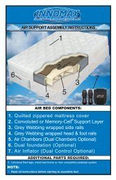
Take all of the components out of the box. You should have the following items:<br />
• Power Edge Support Rail System Includes:<br />
-Attached Head/Foot Rails<br />
-Attached Side Rail Assembly<br />
• Heavy Duty Air Chambers<br />
• Air Inflator Unit With Wired Hand Controls<br />
• Comfort Layer (Either Grey or White Material)<br />
• Mattress Cover/Pillow Top Enclosure<br />
• K or Q Split or Single T/F Foundation (Optional)<br />
2. Your entire Adjustable Air Support System can be easily assembled.<br />
First step, determine where your bed will be positioned<br />
and assemble your support frame. This can be a metal<br />
bed frame, a platform pedestal or the light weight<br />
Versaleg system. Assemble the metal frame or<br />
pedestal in the desired location and place your foundation<br />
in the frame with the open side down. Many platform<br />
pedestals don’t require the use of a foundation. For<br />
VersaLeg assembly, place the foundation halves on<br />
the floor with the open side up. Position the Versaleg<br />
plates on all four corners of each foundation half and<br />
then place one plate on each side approximately half<br />
way between the head and foot plates. Use four of the<br />
provided screws to attach each plate to the foundation.<br />
Repeat this process for the second<br />
foundation piece. Once the plates have<br />
been secured, twist the threaded end of<br />
the Versaleg into each plate. Once all<br />
have been inserted, simply flip the foundation over so the legs<br />
rest upon the ground and you have the firm, flat side of the<br />
foundation is facing up. You are now ready to begin the bed<br />
assembly. For the assembly video of this product please visit:<br />
www.innomax.com or www.youtube.com under the channel name <strong>InnoMax</strong>Sleep<br />
1<br />
AIR SUPPORT ASSEMBLY INSTRUCTIONS<br />
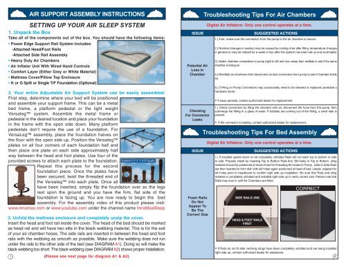
3. Unfold the mattress enclosure and completely unzip the cover.<br />
Insert the head and foot rail inside the cover. The head of the bed should be marked<br />
as head rail and will have two slits in the black webbing material. This is for the exit<br />
of your air chamber hoses. The side rails are inserted in between the head and foot<br />
rails with the webbing as smooth as possible. Make sure the webbing does not run<br />
under the rails to the other side of the bed (see DIAGRAM A1). Doing so will make the<br />
black webbing too short. The black webbing (see DIAGRAM A2) shows proper installation.<br />
(Please see next page for diagram A1 & A2)<br />
ISSUE<br />
Potential Air<br />
Loss In<br />
Chamber<br />
Checking<br />
For Connector<br />
Leaks<br />
ISSUE<br />
Foam Rails<br />
Do Not<br />
Appear To<br />
Be The<br />
Correct Size<br />
Troubleshooting Tips For Air Chambers<br />
Digital Air Inflators: Only one control operates at a time.<br />
SUGGESTED ACTIONS<br />
1.) First, make sure the connection from the pump to the air chamber is secure.<br />
2.) Nominal changes in readout may be caused by cooling of air after filling, temperature changes<br />
in general or may be noticed for a week or two after the system has been set up and acclimated.<br />
3.) Switch chamber connections to pump (right to left and vice versa) then reinflate to see if the same<br />
chamber is losing air.<br />
4.) Reinflate air chambers then disconnect air lock connectors from pump to see if chamber holds<br />
air.<br />
5.) O-Ring on Pump Connectors may occasionally need to be cleaned or replaced (available a<br />
hardware store).<br />
If issue persists, contact authorized dealer for replacement.<br />
*<br />
1.) Check connectors by filling the chamber with air, disconnect the hose from the pump, then<br />
submerge the fitting in a glass of water. If bubbles are coming out of the fitting, a small leak is<br />
present.<br />
If the connector is leaking, contact authorized dealer for replacement.<br />
*<br />
Troubleshooting Tips For Bed Assembly<br />
Digital Air Inflators: Only one control operates at a time.<br />
SIDE RAILS 2ND<br />
HEAD & FOOT RAILS<br />
FIRST<br />
SUGGESTED ACTIONS<br />
1.) If installed upside down or not completely unfolded Rails will not reach top to bottom or side<br />
to side. Properly install by inserting Top to Bottom Rails first. Slit holes in Top to Bottom sling<br />
material should be positioned at head of bed for threading Air Hoses to Pump. Side to Side Rails<br />
are then inserted to form dish with slit holes again positioned at head of bed. Labels adjacent to<br />
slit holes point to headboard to confirm right side up installation. Be sure that Rails and sling<br />
material is completely unfolded and installed right side up to verify correct size. Please note that<br />
Rails may bow in until Air Chambers are filled.<br />
CORRECT<br />
If Rails do not fit after verifying slings have been completely unfolded and are being installed<br />
*<br />
right side up, contact authorized dealer for assistance.<br />
6