Data Sheet - Merazet
Data Sheet - Merazet
Data Sheet - Merazet

You also want an ePaper? Increase the reach of your titles
YUMPU automatically turns print PDFs into web optimized ePapers that Google loves.
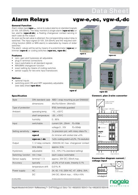
Alarm Relays<br />
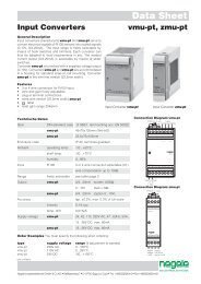
General Function<br />
Alarm relays type vgw-... -serve to output alarms on standard signals<br />
(0-10V, 0/4-20mA). The relay monitors a single alarm (vgw-e/-ec) or<br />
two alarms (vgw-d/-dc), a floating changeover contact serving in<br />
each case as the output.<br />
As soon as the set value is attained, the corresponding output relay is<br />
switched. The input signal (0-10V, 0/4-20mA) and the required switching<br />
function (MAX or MIN alarm) is selectable by means of slider<br />
switches.<br />
The alarm values will be set by means of a potentiometer (vgw-e) or<br />
trimmer (vgw-d) or coding switches (vgw-ec, vgw-dc).<br />
Features<br />
• zero, gain and hysteresis all adjustable<br />
• plug-in terminal connections<br />
• input switchable to all standard signals<br />
• MAX/MIN changeover function<br />
• exact setting by means of coding switches<br />
• sensor supply for two-wire input transducers<br />
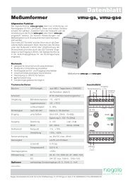
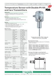
vgw-e<br />
<strong>Data</strong> <strong>Sheet</strong><br />
vgw-e,-ec, vgw-d,-dc<br />
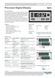
vgw-ec<br />
Options<br />
• optional inputs<br />
• switching point ON and OFF separately adjustable<br />
(see data sheet vgw-dcn)<br />
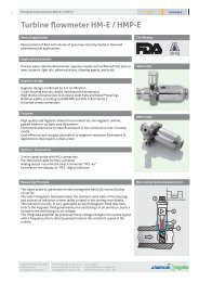
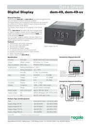
vgw-d<br />
Specification<br />
Style DIN standard case ABS f. snap mounting as per EN50022<br />
dimensions 45x75x105mm (WxHxD)<br />
Type of protection<br />
IP20, terminals guarded<br />
Ambient operating temp. -10...+55°C<br />
shelf temperature -20...+70°C<br />
humidity 0...95%<br />
Input switchable current 0/4...20mA R i<br />
=50Ω<br />
voltage 0...10V R i<br />
=50kΩ<br />
Setting sensitivity vgw-e 1x precision pot. with rotary dial±1%<br />
vgw-d 2x trimmer with slotted dial ±5%<br />
vgw-ec / -dc 1x/2x coding switch ±0,2%, 1% resolution<br />
Output<br />
1 / 2 relay contacts 250V/3A AC max. changeover contact<br />
time delay approx. 0,5s<br />
Hysteresis adjustable 0,5...10% (1%=standard setting)<br />
Switching function min / max each output switchable<br />
Sensor supply terminal 1 / 3 approx. 20V DC / 25mA max.<br />
Accuracy typically ±0,2% of full scale, linearity 0,1%<br />
temperature drift 0,01% /K<br />
Power supply AC 24, 42, 110, 230V AC, 47...63Hz, 3VA,<br />
DC 24V DC, 80mA max., -10%/+15%<br />
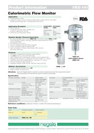
vgw-dc<br />
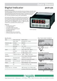
Connect. plan 2-wire converter<br />
Connection diagram current /<br />
voltage input<br />
04.04/Ka PM65<br />
All data subject to change and errors excluded<br />
Negele Messtechnik GmbH • Raiffeisenweg 7 • D-87743 Egg a.d. Günz • Tel. +49(0)8333 / 9204-0 • Fax +49(0)8333 / 9204-49
Order Markings and Types<br />
model setting 24V AC 115V AC 230V AC 24V DC<br />
1 alarm value 1x potentiometer vgw-e 24V AC vgw-e 115V AC vgw-e 230V AC vgw-e 24V DC<br />
2 alarm values 2x trimmers vgw-d 24V AC vgw-d 115V AC vgw-d 230V AC vgw-d 24V DC<br />
1 alarm value 1x coding switch vgw-ec 24V AC vgw-ec 115V AC vgw-ec 230V AC vgw-ec 24V DC<br />
2 alarm values 2x coding switches vgw-dc 24V AC vgw-dc 115V AC vgw-dc 230V AC vgw-dc 24V DC<br />
Trimmers and setting switches<br />
name function setting<br />
S1 input (I/U) current(I) / voltage (U)<br />
S2 current input (0/4mA) 0-20mA / 4-20mA<br />
S3 switching function alarm value 2 min / max<br />
S4 switching function alarm value 1 min / max<br />
P1 zero setting (N) never change<br />
P2 gain setting (V) never change<br />
P3 hysteresis alarm value 2 0,5...10%<br />
P4 hysteresis alarm value 1 0,5...10%<br />
view vgw-d/-dc (cover open)<br />
Device settings<br />
1. Set alarm relay with "S1" and "S2" to required input.<br />
2. Set switching function for alarm value 1 and 2 as needed ("S3"/"S4").<br />
3. Connect setpoint transmitter or other signal source to input (terminals 2/3).<br />
4. Apply power supply (terminals 9/10).<br />
5. Adjust required alarm values (e.g. 50%) by means of coding switches.<br />
6. Slowly increase or reduce respectively the input signal up to the set alarm value<br />
and check the switching function.<br />
7. Set by means of trimmer "P3" or "P4" respectively the hysteresis you need<br />
(0,5... 10%) and check by means of changing the input signal.<br />
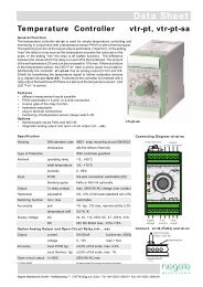
Status diagrams(input 0-20mA or 0-10V)<br />
Function maximum alarm value diagram 1<br />
• switch S3 / S4: "max"<br />
• alarm value: 50%<br />
• hysteresis: 10%<br />
Function minimum alarm value diagram 2<br />
• switch S3 / S4: "min"<br />
• alarm value: 50%<br />
• hysteresis: 10%