Data Sheet - Merazet
Data Sheet - Merazet
Data Sheet - Merazet

Create successful ePaper yourself
Turn your PDF publications into a flip-book with our unique Google optimized e-Paper software.
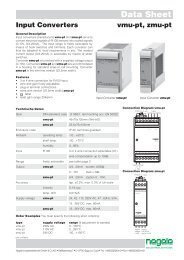
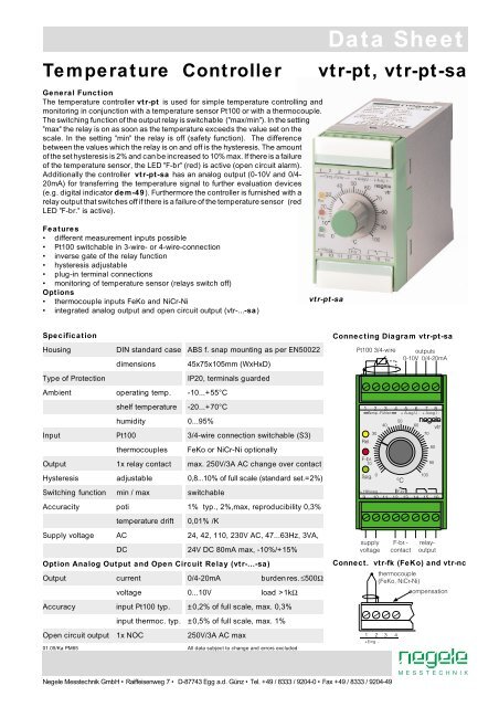
Temperature Controller<br />
General Function<br />
The temperature controller vtr-pt is used for simple temperature controlling and<br />
monitoring in conjunction with a temperature sensor Pt100 or with a thermocouple.<br />
The switching function of the output relay is switchable ("max/min"). In the setting<br />
"max" the relay is on as soon as the temperature exceeds the value set on the<br />
scale. In the setting "min" the relay is off (safety function). The difference<br />
between the values which the relay is on and off is the hysteresis. The amount<br />
of the set hysteresis is 2% and can be increased to 10% max. If there is a failure<br />
of the temperature sensor, the LED "F-br" (red) is active (open circuit alarm).<br />
Additionally the controller vtr-pt-sa has an analog output (0-10V and 0/4-<br />
20mA) for transferring the temperature signal to further evaluation devices<br />
(e.g. digital indicator dem-49). Furthermore the controller is furnished with a<br />
relay output that switches off if there is a failure of the temperature sensor (red<br />
LED "F-br." is active).<br />
<strong>Data</strong> <strong>Sheet</strong><br />
vtr-pt, vtr-pt-sa<br />
Features<br />
• different measurement inputs possible<br />
• Pt100 switchable in 3-wire- or 4-wire-connection<br />
• inverse gate of the relay function<br />
• hysteresis adjustable<br />
• plug-in terminal connections<br />
• monitoring of temperature sensor (relays switch off)<br />
Options<br />
• thermocouple inputs FeKo and NiCr-Ni<br />
• integrated analog output and open circuit output (vtr-...-sa)<br />
vtr-pt-sa<br />
Specification<br />
Housing DIN standard case ABS f. snap mounting as per EN50022<br />
dimensions 45x75x105mm (WxHxD)<br />
Type of Protection<br />
IP20, terminals guarded<br />
Ambient operating temp. -10...+55°C<br />
shelf temperature -20...+70°C<br />
humidity 0...95%<br />
Input Pt100 3/4-wire connection switchable (S3)<br />
thermocouples FeKo or NiCr-Ni optionally<br />
Output 1x relay contact max. 250V/3A AC change over contact<br />
Hysteresis adjustable 0,8...10% of full scale (standard set.=2%)<br />
Switching function min / max switchable<br />
Accuracity poti 1% typ., 2%,max, reproducibility 0,3%<br />
temperature drift 0,01% /K<br />
Supply voltage AC 24, 42, 110, 230V AC, 47...63Hz, 3VA,<br />
DC 24V DC 80mA max, -10%/+15%<br />
Option Analog Output and Open Circuit Relay (vtr-...-sa)<br />
Output current 0/4-20mA burden res. ≤500Ω<br />
voltage 0...10V load >1kΩ<br />
Accuracy input Pt100 typ. ±0,2% of full scale, max. 0,3%<br />
input thermoc. typ. ±0,5% of full scale, max. 1%<br />
Open circuit output 1x NOC 250V/3A AC max<br />
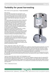
Connecting Diagram vtr-pt-sa<br />
Connect. vtr-fk (FeKo) and vtr-nc<br />
01.05/Ka PM65<br />
All data subject to change and errors excluded<br />
Negele Messtechnik GmbH • Raiffeisenweg 7 • D-87743 Egg a.d. Günz • Tel. +49 / 8333 / 9204-0 • Fax +49 / 8333 / 9204-49
Order Markings and Types<br />
range curr. outp./open circ. 24V AC 115V AC 230V AC 24V DC<br />
0-50°C — / F-br.-LED vtr-pt 0-50 24VAC vtr-pt 0-50 115VAC vtr-pt 0-50 230VAC vtr-pt 0-50 24VDC<br />
0-50°C 0/4-20mA / F-br. contact vtr-pt-sa 0-50 24VAC vtr-pt-sa 0-50 115VAC vtr-pt-sa 0-50 230VAC vtr-pt-sa 0-50 24VDC<br />
0-100°C — / F-br.-LED vtr-pt 0-100 24VAC vtr-pt 0-100 115VAC vtr-pt 0-100 230VAC vtr-pt 0-100 24VDC<br />
0-100°C 0/4-20mA / F-br. contact vtr-pt-sa 0-100 24VAC vtr-pt-sa 0-100 115VAC vtr-pt-sa 0-100 230VAC vtr-pt-sa 0-100 24VDC<br />
0-200°C — / F-br.-LED vtr-pt 0-200 24VAC vtr-pt 0-200 115VAC vtr-pt 0-200 230VAC vtr-pt 0-200 24VDC<br />
0-200°C 0/4-20mA / F-br. contact vtr-pt-sa 0-200 24VAC vtr-pt-sa 0-200 115VAC vtr-pt-sa 0-200 230VAC vtr-pt-sa 0-200 24VDC<br />
Trimmers and Switches<br />
name function setting<br />
S1 current output (0/4mA) 0-20mA / 4-20mA (only ...-sa)<br />
S2 function switching output min / max<br />
S3 input selection Pt100 (3/4-wire) 3-wire / 4-wire<br />
P1 zero setting (N) do not change<br />
P2 gain setting (V) do not change<br />
P3 hysteresis switching output 0,8...10%<br />
Settings and Starting Instructions<br />
1. Set device with switches S1...S3 according to table mentioned above.<br />
2. Connect temperature sensor or simulator (e.g. hsm-p) to input (if Pt100 pay<br />
attention to 3-wire or 4-wire-connection, see setting of S3).<br />
3. Apply supply voltage (terminals 9/10).<br />
4. Set switching temperature you need (e.g. 50°C) by means of potentiometer front<br />
side.<br />
5. Increase or decrease temperature slowly to adjust setpoint and check the switching<br />
function (yellow LED is on, if relay is active).<br />
6. Set with trimmer P3 the hysteresis you need (0,8... 10% of full scale) and check<br />
it by slowly varying the temperature (diagram 1+2).<br />
7. Disconnect the Pt100 sensor and check the open circuit alarm (red LED is on,<br />
both relays are inactive).<br />
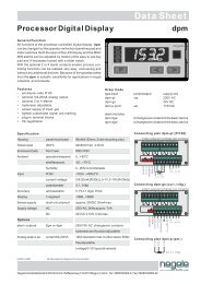
view vtr-pt-sa (cover open)<br />
pcb<br />
0...20mA<br />
S1 current output<br />
4...20mA<br />
P3 hysteresis<br />
min<br />
S2 switching<br />
function<br />
max<br />
P2 V<br />
P1 Np<br />
4-wire<br />
S3 Pt 100<br />
connect.<br />
3-wire<br />
Option vtr-...-sa Analog Output and Open Circuit Alarm<br />
The analog output (e. g. 4...20mA) is corresponding to the whole temperature range<br />
of the controller (e. g. 0...200°C).<br />
Controllers with analog output are furnished with an open circuit alarm , that is active<br />
when<br />
• breakdown of supply voltage,<br />
• short circuit of temperature sensor,<br />
• open circuit of temperature sensor<br />
and disconnect contact of terminals 12/13 and switches the relays "Ausgang" inactive<br />
(current and voltage output are switching to "0mA" or "0V" respectively).<br />
Function Maximum Alarm Diagram 1<br />
• switch S1: "max"<br />
• setpoint: 50°C<br />
• hysteresis P3: 10°C<br />
Function Minimum Alarm Diagram 2<br />
• switch S1: "min"<br />
• setpoint: 50°C<br />
• hysteresis P3: 10°C