The Medicina IRA-SKA Engineering Group
The Medicina IRA-SKA Engineering Group
The Medicina IRA-SKA Engineering Group

You also want an ePaper? Increase the reach of your titles
YUMPU automatically turns print PDFs into web optimized ePapers that Google loves.
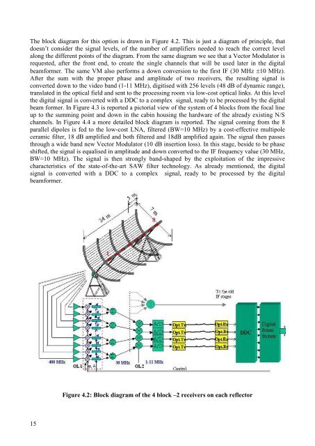
<strong>The</strong> block diagram for this option is drawn in Figure 4.2. This is just a diagram of principle, that<br />
doesn’t consider the signal levels, of the number of amplifiers needed to reach the correct level<br />
along the different points of the diagram. From the same diagram we see that a Vector Modulator is<br />
requested, after the front end, to create the single channels that will be used later in the digital<br />
beamformer. <strong>The</strong> same VM also performs a down conversion to the first IF (30 MHz 10 MHz).<br />
After the sum with the proper phase and amplitude of two receivers, the resulting signal is<br />
converted down to the video band (1-11 MHz), digitised with 256 levels (48 dB of dynamic range),<br />
translated in the optical field and sent to the processing room via low-cost optical links. At this level<br />
the digital signal is converted with a DDC to a complex signal, ready to be processed by the digital<br />
beam former. In Figure 4.3 is reported a pictorial view of the system of 4 blocks from the focal line<br />
up to the summing point and down in the cabin housing the hardware of the already existing N/S<br />
channels. In Figure 4.4 a more detailed block diagram is reported. <strong>The</strong> signal coming from the 8<br />
parallel dipoles is fed to the low-cost LNA, filtered (BW=10 MHz) by a cost-effective multipole<br />
ceramic filter, 18 dB amplified and both filtered and 18dB amplified again. <strong>The</strong> signal then passes<br />
through a wide band new Vector Modulator (10 dB insertion loss). In this stage, beside to be phase<br />
shifted, the signal is equalised in amplitude and down converted to the IF frequency value (30 MHz,<br />
BW=10 MHz). <strong>The</strong> signal is then strongly band-shaped by the exploitation of the impressive<br />
characteristics of the state-of-the-art SAW filter technology. As already mentioned, the digital<br />
signal is converted with a DDC to a complex signal, ready to be processed by the digital<br />
beamformer.<br />
Figure 4.2: Block diagram of the 4 block –2 receivers on each reflector<br />
15