The Medicina IRA-SKA Engineering Group
The Medicina IRA-SKA Engineering Group
The Medicina IRA-SKA Engineering Group

Create successful ePaper yourself
Turn your PDF publications into a flip-book with our unique Google optimized e-Paper software.
<strong>The</strong> band-limited signal is down converted to the video band, filtered again, digitised (8 bit), and<br />
sent, via a low-cost optical link, to the data processing room, distant about 900 m (worst case). A<br />
sum of every single receiver inside the single channels is sent to the already existing IF stages.<br />
4.1.2 Eight single receivers on each reflector:<br />
In this solution we consider 8 single receivers on each single cylindrical reflector. <strong>The</strong> number of<br />
receivers installed on the total N/S would be 512 as in the previous case. This is the maximum<br />
number of receivers installable on the N/S arm without changing the focal line design. Due to the<br />
mechanical structure of such an antenna, it should be very easy to change (if requested) the old<br />
dipoles with a new design low-cost wide-band printed sensors on the same focal line. In this case<br />
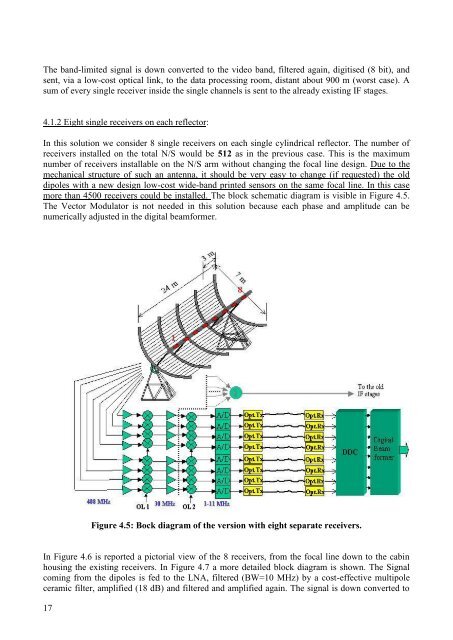
more than 4500 receivers could be installed. <strong>The</strong> block schematic diagram is visible in Figure 4.5.<br />
<strong>The</strong> Vector Modulator is not needed in this solution because each phase and amplitude can be<br />
numerically adjusted in the digital beamformer.<br />
Figure 4.5: Bock diagram of the version with eight separate receivers.<br />
In Figure 4.6 is reported a pictorial view of the 8 receivers, from the focal line down to the cabin<br />
housing the existing receivers. In Figure 4.7 a more detailed block diagram is shown. <strong>The</strong> Signal<br />
coming from the dipoles is fed to the LNA, filtered (BW=10 MHz) by a cost-effective multipole<br />
ceramic filter, amplified (18 dB) and filtered and amplified again. <strong>The</strong> signal is down converted to<br />
17