A Digital Backend Architecture for Fourier Imaging
A Digital Backend Architecture for Fourier Imaging
A Digital Backend Architecture for Fourier Imaging

Create successful ePaper yourself
Turn your PDF publications into a flip-book with our unique Google optimized e-Paper software.
A <strong>Digital</strong> <strong>Backend</strong> <strong>Architecture</strong><br />
<strong>for</strong> <strong>Fourier</strong> <strong>Imaging</strong><br />
A. Mattana, M. Bartolini, G. Naldi<br />
IRA 449/11
Referee: Andrea Orlati<br />
1
Contents<br />
Preface 3<br />
Chapter I: <strong>Digital</strong> <strong>Backend</strong>s 4<br />
CASPER group 4<br />
ROACH 4<br />
Programming and Libraries 5<br />
Introducing the project 7<br />
Clock Signals 9<br />
Network Scheme 10<br />
Chapter II: F-engine 12<br />
Data acquisition 13<br />
Filtering sub-bands 14<br />
X-engine branch 18<br />
Amplitude and Phase Equalization 19<br />
Quantization 21<br />
Formatting data <strong>for</strong> next engines 22<br />
S-engine branch 39<br />
Quantization 41<br />
Control Signals and Registers 50<br />
Chapter III: X-engine Correlator 57<br />
Getting data from F-engine 58<br />
Correlation 61<br />
Control Signals and Registers 75<br />
Chapter IV: S-engine Spatial FFT 79<br />
Getting data from F-engine 80<br />
2D FFT 83<br />
Control Signals and Registers 98<br />
Acronyms 101<br />
Bibliography 102<br />
2
Preface<br />
This document wants to describe a possible FPGA architecture to develop a <strong>Fourier</strong> Imager using<br />
the Medicina Northern Cross Radio telescope. The test bed <strong>for</strong> this project is a portion of the North-South<br />
arm also knows as BEST-2 (Basic Element <strong>for</strong> SKA Training), it is a 8 cylinders having 4 RX each in single<br />
polarization.<br />
The digital backend used is a CASPER (Parsons, A., et al., "<strong>Digital</strong> Instrumentation <strong>for</strong> the<br />
Radio Astronomy Community", astro-ph/0904.1181, April 2009) board based on XILINX FPGAs,<br />
the ROACH board.<br />
The development has been per<strong>for</strong>med by using the Xilinx System Generator embedded in<br />
the Mathworks Matlab which allows to use a Xilinx Blockset plus custom radio astronomy<br />
libraries realized by the CASPER CONSORTIUM.<br />
In order to simplify the reading of this book the description of the activity of each block has<br />
been rotated in a horizontal layout, the input signals come from left and the result signals leave<br />
to the right. Where no explicit, time goes from right to left.<br />
This document describes only the project architecture and not the software running on the<br />
workstation or the radio astronomic post processing tools.<br />
This project has been realized in collaboration with the Ox<strong>for</strong>d University, and a special<br />
thanks goes to Kris Zarb-Adami, Jack Hickish, Griffin Foster, Danny Price, and the local team at<br />
IRA, Stelio Montebugnoli, Germano Bianchi and Marco Schiaffino.<br />
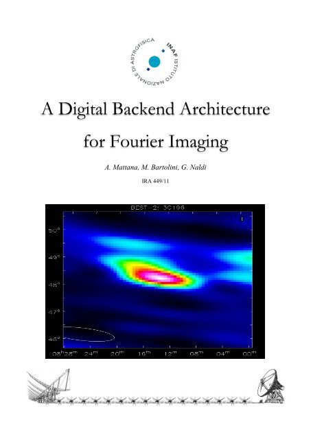
The image in the cover is a result obtain after the post processing done by Griffin Foster.<br />
3
<strong>Digital</strong> <strong>Backend</strong>s<br />
CASPER group<br />
The term CASPER means “Collaboration <strong>for</strong> Astronomy Signal Processing and Electronics<br />
Research”. The CASPER was born at the Berkeley University of Cali<strong>for</strong>nia, with a collaborations of<br />
several institute and laboratories. The primary goal of CASPER is to streamline and simplify the<br />
design flow of radio astronomy instrumentation by promoting design reuse through the<br />
development of plat<strong>for</strong>m-independent, open-source hardware and software.<br />
The CASPER group aim is to couple the real-time streaming per<strong>for</strong>mance of applicationspecific<br />
hardware with the design simplicity of general-purpose software. By providing<br />
parameterized, plat<strong>for</strong>m independent gateware libraries that run on reconfigurable, modular<br />
hardware building blocks, we abstract away low-level implementation details and allow<br />
astronomers to rapidly design and deploy new instruments.<br />
ROACH<br />
Reconfigurable Open <strong>Architecture</strong> Computing Hardware is the last CASPER released board.<br />
The ROACH has in total 4 FPGA:<br />
• a Xilinx VIRTEX 5 (package: XC5VSX95T-1FF1136) dedicated <strong>for</strong> the user as DSP<br />
• an AMCC 440EPx Embedded Processor is a CPU 400-667MHz as a Linux Power PC<br />
• an Actel AFS600 FPGA as a system supervisor<br />
• a Xilinx XC2C256 CPLD as a JTAG programmer emulator<br />
We have 5 ROACH boards at Medicina (up to now) and we need to use 3 of them <strong>for</strong> this<br />
project. The board comes with many interface peripherals such DDR2 RAM, corner turn memory,<br />
gpio pins and leds and high speed data transfer links such 10GbEth link, 10/100 Mb Ethernet link.<br />
Only one ROACH board is dedicated to the data acquisition and the synchronization with the<br />
time and the regularity of the samples is guaranteed from a clock and a PPS signal both locked to<br />
the hydrogen maser atomic clock. The communication between the boards will be implemented<br />
4
with a peer-to-peer XAUI protocol, while the data will be passed to the workstation encapsulated<br />
in UDP packets.<br />
Figure 1: one of the ROACH boards at Medicina without the chassis.<br />
Programming and Libraries<br />
The System Generator is a DSP design tool from Xilinx that enables the use of The Mathworks<br />
model-based design environment Simulink <strong>for</strong> FPGA design. Over 90 DSP building blocks are<br />
provided in the Xilinx DSP blockset <strong>for</strong> Simulink. These blocks include the common DSP building<br />
blocks such as adders, multipliers and registers. Also included are a set of complex DSP building<br />
blocks such as <strong>for</strong>ward error correction blocks, FFTs, filters and memories.<br />
Figure 2: A view of some XILINX blocks used in Simulink<br />
5
These blocks leverage the Xilinx IP core generators to deliver optimized results <strong>for</strong> the<br />
selected device.<br />
The Embedded Development Kit (EDK) is a suite of tools and Intellectual Property (IP) that<br />
enables you to design a complete embedded processor system <strong>for</strong> implementation in a Xilinx<br />
FPGA device. Think of it as an umbrella covering all things related to embedded processor<br />
systems and their design. The Xilinx ISE software must also be installed to run EDK.<br />
The CASPER group has realized an open source library set customized <strong>for</strong> the astronomers<br />
and optimized <strong>for</strong> the FPGAs mounted on their boards, and to easily use the integrated<br />
peripherals.<br />
Figure 3: An example view of the CASPER DSP blockset to synthetize a polyphase filters bank<br />
Programming with the system generator becomes easy with respect to use the VHDL<br />
language and it is very similar to use any electronic IDE tool, simulation included. This is the<br />
reason because this document will be rotated horizontally, in a vertical style you cannot<br />
represent in a good shape the layout of circuits, the view in horizontal is much better also to<br />
represent a signal in the time in a graph.<br />
6
Introducing the project<br />
The antenna acquisition system used <strong>for</strong> this project is the BEST-2 demonstrator. It is a part<br />
of the north-south arm of the Medicina Northern Cross Antenna composed of 8 cylinders having<br />
4 receivers (RX from now on) each. There<strong>for</strong>e there are 32 analogic signals to be sample and<br />
processed. All the Northern Cross does not have a dual polarization. All the RF BEST-2 signals are<br />
transmitted to the receiver control room via optical link preserving any electrical properties.<br />
Figure 4: BEST-2 section of the Medicina Northern Cross Radiotelescope, courtesy of Marco Schiaffino<br />
The Analog to <strong>Digital</strong> converter (AD) installed in the ROACH board computes 64 input x 12 bit<br />
and 40Mbps, and we use only 32 input leaving spare the others. This is a custom AD, the library<br />
to drive the acquisition in Simulink has been written by the Ox<strong>for</strong>d team that has modified also<br />
the polyphase filter bank block to manage the interleaved data flow. The project has been<br />
divided in 3 ROACH boards <strong>for</strong> capability reasons:<br />
• F-engine that acquire the IF signals, filters the input signals in sub-bands and applies<br />
equalizations and quantizations<br />
• X-engine that works as a correlator <strong>for</strong> the array calibration<br />
• S-engine that compute the 2D FFT <strong>for</strong> the imaging<br />
7
V<br />
V<br />
V<br />
V<br />
V V V<br />
V V V<br />
V V V<br />
V V V<br />
Input<br />
G,!<br />
Calibration<br />
V V V V 0 0 0 0<br />
V V V V 0 0 0 0<br />
V V V V 0 0 0 0<br />
V V V V 0 0 0 0<br />
0 0 0 0 0 0 0 0<br />
0 0 0 0 0 0 0 0<br />
0 0 0 0 0 0 0 0<br />
0 0 0 0 0 0 0 0<br />
Zero pad<br />
S<br />
2D FFT<br />
Sky Image<br />
! n 0<br />
Accumulate<br />
x 2<br />
Power<br />
Figure 5: Conceptual project scheme, courtesy of Jack Hickish (Ox<strong>for</strong>d University)<br />
As described in the picture above, the analogic signals coming from the antenna are digitized,<br />
then calibrated, a 2D FFT is applied taking into account the BEST-2 single polarization (the second<br />
pol is zero padded), and finally there is an accumulation of the power spectra. To obtain the<br />
image the analysis needs to be completed with astronomical tools like the NRAO CASA.<br />
8
F engine<br />
ROACH-1<br />
40 Mbps<br />
ADC<br />
64ch<br />
CX-0<br />
CX-1<br />
CX-2<br />
CX-3<br />
CX-0<br />
CX-1<br />
CX-2<br />
CX-3<br />
Internal Oscillator<br />
200 MHz<br />
S engine<br />
ROACH-3<br />
System Generetor set<br />
to arbitrary clock<br />
16 out x 4 ch each x 12 bit<br />
9<br />
pps<br />
Clock<br />
40MHz + 7dBm<br />
CX-0<br />
Internal Oscillator<br />
200 MHz<br />
pps<br />
10MHz<br />
CX-1<br />
CX-2<br />
X engine<br />
ROACH-2<br />
Hydrogen Maser<br />
Atomic Clock<br />
Distributor<br />
Clock Synthetizer<br />
CX-3<br />
System Generetor set<br />
to arbitrary clock<br />
Clock Signals
F engine<br />
ROACH-1<br />
40 Mbps<br />
ADC<br />
64ch<br />
16 out x 4 ch each x 12 bit<br />
CX-0<br />
CX-1<br />
CX-2<br />
CX-3<br />
10Gb eth Link<br />
10Gb eth Link<br />
CX-0<br />
CX-1<br />
CX-2<br />
CX-3<br />
S engine<br />
ROACH-3<br />
10<br />
10/100Mb eth Link<br />
CX-0<br />
10Gb<br />
Ethernet Switch<br />
10Gb eth Link<br />
CX-1<br />
CX-2<br />
X engine<br />
ROACH-2<br />
Network Scheme<br />
CX-3
40 Mbps<br />
ADC<br />
64ch<br />
16ch x 12 bit<br />
(32ch interleaved)<br />
16 out x 4 ch each x 12 bit<br />
PFB<br />
11<br />
Reorder<br />
FFT<br />
F engine<br />
ROACH-1<br />
S engine ROACH-3<br />
Amp EQ<br />
Phase EQ<br />
Quant<br />
Quant<br />
QDR<br />
transpose<br />
and reorder<br />
per antenna<br />
QDR<br />
transpose<br />
X eng<br />
S eng<br />
X engine ROACH-2
40 Mbps<br />
ADC<br />
64ch<br />
PFB Reorder FFT<br />
16 out x 4 ch each x 12 bit<br />
16ch x 12 bit<br />
(32ch interleaved)<br />
12<br />
Amp EQ<br />
Phase EQ<br />
Starting from the F-engine<br />
Quant<br />
Quant<br />
Roach-1<br />
QDR<br />
transpose and<br />
reorder per<br />
antenna<br />
QDR<br />
transpose<br />
X eng<br />
S eng<br />
F engine
40 Mbps<br />
ADC<br />
64ch<br />
16 out x 4 ch each x 12 bit<br />
13<br />
16ch x 12 bit<br />
(32ch interleaved)<br />
0 - 3<br />
4 - 7<br />
Ant0<br />
Ch0<br />
Ant4<br />
Ch0<br />
Ant1<br />
Ch0<br />
Ant5<br />
Ch0<br />
Ant2<br />
Ch0<br />
Ant6<br />
Ch0<br />
Ant3<br />
Ch0<br />
Ant7<br />
Ch0<br />
Ant0<br />
Ch1<br />
Ant4<br />
Ch1<br />
Ant1<br />
Ch1<br />
Ant5<br />
Ch1<br />
dout0<br />
dout1<br />
The 64 input AD takes both the ZDOKs connector<br />
on the ROACH board, there is a supply connector<br />
to allow to plug 64 SMA connectors<br />
F engine
0 - 3<br />
4 - 7<br />
8 - 11<br />
28 - 31<br />
….................…………………………………………………..……….…<br />
Ant0 Ant1 Ant2 Ant3 Ant0 Ant1<br />
Ant4 Ant5 Ant6 Ant7 Ant4 Ant5<br />
Ant8 Ant9 Ant10 Ant11 Ant8 Ant9<br />
……<br />
….................…………………………………………………..……….…<br />
Sample n Sample n+1<br />
Ant28 Ant29 Ant30 Ant31 Ant28 Ant29<br />
dout0<br />
dout1<br />
dout2<br />
doutn<br />
dout7<br />
Customized<br />
PFB block to<br />
handle data<br />
1/4 clocked<br />
14<br />
PFB IN<br />
[12.11] x 32<br />
40 Mbps<br />
ADC<br />
64ch<br />
PFB OUT<br />
[18.17] x 32<br />
Still Real data<br />
16 out x 4 ch each x 12 bit<br />
The customized polyphase filter bank
Reorder<br />
15<br />
0 - 3<br />
4 - 7<br />
8 - 11<br />
28 - 31<br />
….................…………………………………………………..……….…<br />
Ant0 Ant1 Ant2 Ant3 Ant0 Ant1<br />
In_0_3<br />
Ant4 Ant5 Ant6 Ant7 Ant4 Ant5<br />
In_4_7<br />
Ant8 Ant9 Ant10 Ant11 Ant8 Ant9<br />
In_8_11<br />
……<br />
….................…………………………………………………..……….…<br />
Sample n Sample n+1<br />
Ant28 Ant29 Ant30 Ant31 Ant28 Ant29<br />
In_28_31<br />
out_0_3<br />
out_4_7<br />
out_8_11<br />
out_28_31<br />
….................…………………………………………………..……….…<br />
Ch0 Ch1 Ch M-1 Ch M Ch0 Ch1<br />
……<br />
….................…………………………………………………..……….…<br />
Antenna n Antenna n+1<br />
Ch0 Ch1 Ch M-1 Ch M Ch0 Ch1<br />
Ch0 Ch1 Ch M-1 Ch M Ch0 Ch1<br />
Ch0 Ch1 Ch M-1 Ch M Ch0 Ch1<br />
n_fft = 11<br />
Reorder Init<br />
part_reorder = [0:4:2^(n_fft+2)-1];<br />
reorder = [];<br />
<strong>for</strong> multiplex_index = [0:3]<br />
reorder = [reorder,[part_reorder]+multiplex_index];<br />
end<br />
Where M = 2 n_fft - 1<br />
Example using n_fft = 3:<br />
0 4 8 12 16 20 24 28<br />
1 5 9 13 17 21 25 29<br />
2 6 10 14 18 22 26 30<br />
3 7 11 15 19 23 27 31<br />
Data is reordered so that an entire window can be shifted through the FFT<br />
F engine
A real-sampled biplex FFT, with output demuxed by 2<br />
16<br />
in_0-3<br />
in_8-11<br />
in_4-7<br />
in_12-15<br />
in_16-19<br />
in_24-27<br />
in_20-23<br />
in_28-31<br />
Antenna n<br />
….................…………………………………………………..………….… .………………………………………………..……….…<br />
Antenna n+1<br />
Ch0 Ch1 Ch M-1 Ch M Ch0 Ch1<br />
Ch0 Ch1 Ch M-1 Ch M Ch0 Ch1<br />
Ch0 Ch1 Ch M-1 Ch M Ch0 Ch1<br />
Ch0 Ch1 Ch M-1 Ch M Ch0 Ch1<br />
2048 clock cycles <strong>for</strong> each antenna<br />
8192 clock cycles needed<br />
Ch0 Ch1 Ch M-1 Ch M Ch0 Ch1<br />
Ch0 Ch1 Ch M-1 Ch M Ch0 Ch1<br />
Ch0 Ch1 Ch M-1 Ch M Ch0 Ch1<br />
Ch0 Ch1 Ch M-1 Ch M Ch0 Ch1<br />
Antenna n Antenna n+1<br />
Ch0 Ch1 Ch M − 1 Ch M Ch0 Ch1<br />
2 2<br />
out_0_4_1_5_2_6_3_7<br />
…………………….............…<br />
Ch0 Ch1 Ch M − 1 Ch M Ch0 Ch1<br />
2 2<br />
Complex data<br />
re[18.17], im[18.17]<br />
out_8_12_9_13_10_14_11_15<br />
1024 clock cycles <strong>for</strong> each antenna<br />
8192 clock cycles needed<br />
…………………….............…<br />
Ch0 Ch1 Ch M − 1 Ch M Ch0 Ch1<br />
2 2<br />
Ch0 Ch1 Ch M − 1 Ch M Ch0 Ch1<br />
2 2<br />
out_16_20_17_21_18_22_19_23<br />
Complex data<br />
re[18.17], im[18.17]<br />
out_24_28_25_29_26_30_27_31<br />
F engine<br />
n_fft = 11<br />
M = 2 n_fft - 1
In order to make more readable this document we<br />
assume from now on this new antennas numbering<br />
which we will taking into account at the and<br />
FFT real output sequence New numbering Prefix<br />
17<br />
0-4-1-5-2-6-3-7 0-1-2-3-5-6-7 0-7<br />
8_12_9_13_10_14_11_15 8-9-10-11-12-13-14-15 8-15<br />
16_20_17_21_18_22_19_23 16-17-18-19-20-21-22-23 16-23<br />
24_28_25_29_26_30_27_31 24-25-26-27-28-29-30-31 24-31<br />
!! IMPORTANT !!<br />
F engine
40 Mbps<br />
ADC<br />
64ch<br />
PFB Reorder FFT<br />
16 out x 4 ch each x 12 bit<br />
8ch x 12 bit<br />
(32ch interleaved)<br />
18<br />
Amp EQ<br />
Following the<br />
X-engine branch<br />
Phase EQ<br />
Quant<br />
QDR<br />
transpose and<br />
reorder per<br />
antenna<br />
Quant<br />
QDR<br />
transpose<br />
consider in the first iteration phase<br />
correction factors all zeroes<br />
X eng<br />
S eng
Equalise amplitude and pass data to be quantized to 4 bits and sent to the<br />
X engine over XAUI 18 bit precision is maintained so that phase corrections<br />
can be added to the data stream going to the fft imaging system.<br />
Amp EQ0<br />
19<br />
(bitwidth fft) 18.17 *<br />
(gain factor) 32.00 =<br />
50.17 b<br />
F engine
Phase corrections preparations<br />
20<br />
c_mult details<br />
At the beginning all coefficients<br />
are set to zero and data has to<br />
send to the x-engine<br />
F engine<br />
(bitwidth fft) 18.17 *<br />
(phase correction) 16.15 =<br />
35.32 b
Quantization<br />
21<br />
From 18.17 (x2) to 4.3 (x2), quant_x_eng 32 bit<br />
quant_x_eng<br />
a0c0, a0c1, …, a0c1023, a1c0, a1c1, …, a7c1023<br />
a8c0, a8c1, …, a8c1023, a9c0, a9c1, …, a15c1023<br />
a16c0, a16c1, …, a16c1023, a17c0, a17c1, …, a23c1023<br />
a24c0, a24c1, …, a24c1023, a25c0, a25c1, …, a31c1023<br />
t 0 t 1 t M<br />
F engine<br />
2<br />
t M 2<br />
+1 t M 2<br />
+2 t M<br />
2<br />
∗ 8
X engine expects groups of a single channel and a single antenna<br />
22<br />
Chan_reorder init<br />
pr = [0 512];<br />
n_chan = 1024;<br />
map = []<br />
<strong>for</strong> i=[0:(n_chan/2)-1]<br />
map=[map, pr+i];<br />
end<br />
(result map:<br />
0 512 1 513 2 514 3 515...<br />
...510 1022 511 1023)<br />
t 0 t 1 t end<br />
a0c0 a0c1 a7c1023<br />
a8c0 a8c1 a15c1023<br />
a16c0 a16c1 a23c1023<br />
a24c0 a24c1 a31c1023<br />
t R0 t R1 t Rend<br />
a0c0 a0c512 a7c1023<br />
a8c0 a8c512 a15c1023<br />
a16c0 a16c512 a23c1023<br />
a24c0 a24c512 a31c1023<br />
X0 X1 X8191<br />
F engine
X engine expects groups of a single channel and a single antenna<br />
Using QDR1 as 2 10 x 2 10 matrix<br />
23<br />
t R0 t R1 t R1024 t Rend<br />
a0c0 a0c512 a1c0 a7c1023<br />
a8c0 a8c512 a9c0 a15c1023<br />
a16c0 a16c512 a17c0 a23c1023<br />
a24c0 a24c512 a25c0 a31c1023<br />
X0 X1 X1024 X8191<br />
Μ =<br />
C 0 C 1 C 1022 C 1023<br />
R 0<br />
X0 X1 X1022 X1023<br />
R 1<br />
X2^10 X1025 X(2^10)*2-2 X(2^10)*2-1<br />
R 2<br />
X(2^10)*2 X(2^10)*2+1 X(2^10)*3-2 X(2^10)*3-1<br />
R 1022<br />
X(2^10)*1022 X(2^10)*1022+1 X(2^10)*1023-2 X(2^10)*1023-1<br />
R 1023<br />
X(2^10)*1023 X(2^10)*1023+1 X(2^10)*1024-2 X(2^10)*1024-1<br />
1024*1024 cells means also 128 spectra of each antenna<br />
(8192 needed <strong>for</strong> one spectra)<br />
F engine
X engine expects groups of a single channel and a single antenna<br />
24<br />
C 0 C 1 C 1022 C 1023<br />
R 0-7<br />
Spectrum1 of 32 antennas in 8 row (8x1024)<br />
Μ =<br />
R 8-15<br />
Spectrum2 of 32 antennas in 8 row (8x1024)<br />
R 16-32<br />
Spectrum3 of 32 antennas in 8 row (8x1024)<br />
…<br />
R 1016-1023<br />
Spectrum128 of 32 antennas in 8 row (8x1024)<br />
1024*1024 cells means also 128 spectra of each antenna<br />
(8192 needed <strong>for</strong> one spectra)<br />
F engine
X engine expects groups of a single channel and a single antenna<br />
25<br />
x15 x14 x13 x12 x11 x10 x9 x8 x7 x6 x5 x4 x3 x2 x1 x0<br />
t<br />
x0 x1 x2 x3<br />
x4 x5 x6 x7<br />
x8 x9 x10 x11<br />
x12 x13 x14 x15<br />
Considering time moving from left to right, the QDR transpose data as shown below<br />
x0 x4 x8 x12<br />
x1 x5 x9 x13<br />
x2 x6 x10 x14<br />
x3 x7 x11 x15<br />
x15 x11 x7 x3 x14 x10 x6 x2 x13 x9 x5 x1 x12 x8 x4 x0<br />
F engine<br />
t
X engine expects groups of a single channel and a single antenna<br />
26<br />
C 0 C 1 C 1022 C 1023<br />
R 0<br />
X0 X2^10 X(2^10)*1022 X(2^10)*1023<br />
Μ T =<br />
R 1<br />
X1 X2^10+1 X(2^10)*1022+1 X(2^10)*1023+1<br />
R 2<br />
X2 X2^10+2 X(2^10)*1022+2 X(2^10)*1023+2<br />
R 1022<br />
X1022 X(2^10)*2-2 X(2^10)*1023-2 X(2^10)*1024-2<br />
R 1023<br />
X1023 X(2^10)*2-1 X(2^10)*1023-1 X(2^10)*1024-1<br />
F engine
X engine expects groups of a single channel and a single antenna<br />
27<br />
Every 8 column the same frequency channel is referring to the next spectra,<br />
next channels are grouped by 8x128 (=1024=2^10)<br />
t 0 t 1 t 2 t 8 t 2^10 t 2^20<br />
a0c0 a1c0 a2c0 a0c0 a0c1 a7c1023<br />
Μ T =<br />
a8c0 a9c0 a10c0 a8c0 a8c1 a15c1023<br />
a16c0 a17c0 a18c0 a16c0 a16c1 a23c1023<br />
a24c0 a25c0 a26c0 a24c0 a24c1 a31c1023<br />
X0 X2^10 X(2^10)*2 X(2^10)*8 X1 X(2^20)<br />
F engine
X engine expects groups of a single channel and a single antenna<br />
28<br />
The reorder map at this stage groups data by 8 (let’s call M T8 )<br />
[0 8 16 24 32 … 1008 1016 1 9 17 … 999 1007 1015 1023]<br />
There<strong>for</strong>e grouping same channels of different acquisitions<br />
t 0 t 1 t 2 t 127 t 128 t 2^10 t 2^20<br />
a0c0 a0c0 a0c0 a0c0 a1c0 a0c1 a7c1023<br />
Μ T8 =<br />
a8c0 a8c0 a8c0 a8c0 a9c0 a8c1 a15c1023<br />
a16c0 a16c0 a16c0 a16c0 a17c0 a16c1 a23c1023<br />
a24c0 a24c0 a24c0 a24c0 a25c0 a24c1 a31c1023<br />
X0 X(2^10)*8 X(2^10)*16 X(2^10)*1016 X2^10 X1 X(2^20)<br />
F engine
X engine expects groups of a single channel and a single antenna<br />
29<br />
F engine
X engine expects groups of a single channel and a single antenna<br />
30<br />
Uncram split a 32 bit word in two separate streams of 16 bit (high and low)<br />
Square transposer presents a number of parallel inputs serially on the same<br />
number of output lines.<br />
F engine
X engine expects groups of a single channel and a single antenna<br />
31<br />
y2049<br />
y257<br />
a0c1 … … … a1c0<br />
a8c1 … … … a9c0<br />
y255 y3 y1<br />
a0c0 … a0c0 a0c0<br />
a8c0 … a8c0 a8c0<br />
a16c1 … … … a17c0<br />
a24c1 … … … a25c0<br />
a16c0 … a16c0 a16c0<br />
a24c0 … a24c0 a24c0<br />
=<br />
… y5 y3 y1<br />
… y6 y4 y2<br />
… … y5 y2 y1<br />
… … y8 y4 y3<br />
y2050<br />
y258<br />
y256<br />
y4<br />
y2<br />
128t<br />
t 1025<br />
8x128t<br />
F engine
X engine expects groups of a single channel and a single antenna<br />
32<br />
y6<br />
y5<br />
y2<br />
y1<br />
… … y5 y2 y1<br />
… … y8 y4 y3<br />
t<br />
=<br />
… … … a16c0 a0c0 a16c0 a0c0<br />
… … … a24c0 a8c0 a24c0 a8c0<br />
… … … a16c0 a0c0 a16c0 a0c0<br />
… … … a24c0 a8c0 a24c0 a8c0<br />
y8<br />
y7<br />
y4<br />
y3<br />
… t 2<br />
t 1<br />
t 0<br />
F engine
X engine expects groups of a single channel and a single antenna<br />
33<br />
Reorder_one_ant_a_time init<br />
spec_chan = 10; % mask parameter<br />
block_size = 7; % mask parameter<br />
partial_reorder = [0:2:2^block_size - 1]<br />
reorder = []<br />
<strong>for</strong> n = [0:1]<br />
reorder = [reorder, [partial_reorder]+n];<br />
end<br />
(result: [0 2 4 6 ... 126 1 3 5 7 ... 127])<br />
F engine
X engine expects groups of a single channel and a single antenna<br />
34<br />
… … y9 y5 y1<br />
… … y11 y7 y3<br />
t<br />
=<br />
y69<br />
y65<br />
y9<br />
y5<br />
y1<br />
… a16c0 a0c0 … a0c0 a0c0 a0c0<br />
… a24c0 a8c0 … a8c0 a8c0 a8c0<br />
… a16c0 a0c0 … a0c0 a0c0 a0c0<br />
… a24c0 a8c0 … a8c0 a8c0 a8c0<br />
y71<br />
y67<br />
y11<br />
y7<br />
y3<br />
t 65<br />
t 64<br />
t 3<br />
t 2<br />
t 1<br />
F engine
64 clock cycle <strong>for</strong> a complete set of 128 samples of the same frequency<br />
channel of 2 antennas (complex number, r/i 4.3 bit each)<br />
(read this table from right to left and bottom up!)<br />
t Z17 t Z16 t Z15 t Z14 t Z13 t Z12 t Z11 t Z10 t Z9<br />
a16c1 a0c1 a23c0 a7c0 a22c0 a6c0 a21c0 a5c0 a20c0<br />
a24c1 a8c1 a31c0 a15c0 a30c0 a14c0 a29c0 a13c0 a28c0<br />
a16c1 a0c1 a23c0 a7c0 a22c0 a6c0 a21c0 a5c0 a20c0<br />
a24c1 a8c1 a31c0 a15c0 a30c0 a14c0 a29c0 a13c0 a28c0<br />
35<br />
64t 64t 64t 64t 64t 64t 64t 64t 64t<br />
t Z8 t Z7 t Z6 t Z5 t Z4 t Z3 t Z2 t Z1 t Z0<br />
a4c0 a19c0 a3c0 a18c0 a2c0 a17c0 a1c0 a16c0 a0c0<br />
a12c0 a27c0 a11c0 a26c0 a10c0 a25c0 a9c0 a24c0 a8c0<br />
a4c0 a19c0 a3c0 a18c0 a2c0 a17c0 a1c0 a16c0 a0c0<br />
a12c0 a27c0 a11c0 a26c0 a10c0 a25c0 a9c0 a24c0 a8c0<br />
64t 64t 64t 64t 64t 64t 64t 64t 64t<br />
F engine
32 bit x 64t each<br />
antennas interlived by 8 bit<br />
X engine data order<br />
t Z15 t Z14 t Z13 t Z12 t Z11 t Z10 t Z9 t Z8 t Z7 t Z6 t Z5 t Z4 t Z3 t Z2 t Z1 t Z0<br />
a23 a7 a22 a6 a21 a5 a20 a4 a19 a3 a18 a2 a17 a1 a16 a0<br />
a31 a15 a30 a14 a29 a13 a28 a12 a27 a11 a26 a10 a25 a9 a24 a8<br />
Considering the original number the X-engine<br />
will receive data in this order<br />
FFT real output sequence New numbering Prefix<br />
36<br />
0-4-1-5-2-6-3-7 0-1-2-3-4-5-6-7 0-7<br />
8_12_9_13_10_14_11_15 8-9-10-11-12-13-14-15 8-15<br />
16_20_17_21_18_22_19_23 16-17-18-19-20-21-22-23 16-23<br />
24_28_25_29_26_30_27_31 24-25-26-27-28-29-30-31 24-31<br />
the final sequence is<br />
t Z15 t Z14 t Z13 t Z12 t Z11 t Z10 t Z9 t Z8 t Z7 t Z6 t Z5 t Z4 t Z3 t Z2 t Z1 t Z0<br />
a23 a7 a19 a3 a22 a6 a18 a2 a21 a5 a17 a1 a20 a4 a16 a0<br />
a31 a15 a27 a11 a30 a14 a26 a10 a29 a13 a25 a9 a28 a12 a24 a8<br />
F engine
Packing data to send over XAUI CX4 to X engine ROACH<br />
37<br />
The 'antenna' number is used to index the<br />
packets which make up one integration.<br />
Data is tagged with a ‘mcnt’ number and<br />
sync and eof headers.<br />
These are later decoded and used <strong>for</strong> error<br />
checking and data ordering in the X-engines<br />
F engine
…packaging…<br />
data in: 128 samples * 2 ant * 8b each = 32b * 64t = 32 words * 64b<br />
38<br />
ant_bits = 4 (2 4 = 16 antennas in dual pol, instead of 32 ant single pol)<br />
nwrd_bits = 5 (2 5 = 32 payload length)<br />
clk_cnt #bits = 48 + ant_bits + nwrd_bits + 1<br />
(the last additional bit is needed to concatenate and validate 64bit of data)<br />
mcnt #bits = 48 (counts the channel frequencies)<br />
header #bits = 64 = mcnt[48] + zeroes pads + ant[4]<br />
F engine
40 Mbps<br />
ADC<br />
64ch<br />
PFB Reorder FFT<br />
16 out x 4 ch each x 12 bit<br />
16ch x 12 bit<br />
(32ch interleaved)<br />
39<br />
Amp EQ<br />
Phase EQ<br />
Following the<br />
S-engine branch<br />
Quant<br />
QDR<br />
transpose and<br />
reorder per<br />
antenna<br />
Quant<br />
QDR<br />
transpose<br />
phase corrections allow to<br />
proceed with the spatial FFT<br />
X eng<br />
S eng
Phase corrections done!<br />
40<br />
Phase corrections are<br />
obtained multiplying the<br />
complex conjugate of the<br />
new coefficents<br />
c_mult details<br />
F engine<br />
(bitwidth fft) 18.17 *<br />
(phase correction) 16.15 =<br />
35.32 b
Quantization<br />
41<br />
From 35.32 (x2) to 4.3 (x2), quant_fft 32 bit<br />
quant_fft<br />
a0c0, a0c1, …, a0c1023, a1c0, a1c1, …, a7c1023<br />
a8c0, a8c1, …, a8c1023, a9c0, a9c1, …, a15c1023<br />
a16c0, a16c1, …, a16c1023, a17c0, a17c1, …, a23c1023<br />
a24c0, a24c1, …, a24c1023, a25c0, a25c1, …, a31c1023<br />
t 0 t 1 t M<br />
F engine<br />
2<br />
t M 2<br />
+1 t M 2<br />
+2 t M<br />
2<br />
∗ 8
The <strong>Fourier</strong> Imager (S engine) expects blocks<br />
of all antennas per one frequency channel<br />
42<br />
This is done by using the second Corner Turn Memory (QDR)<br />
available aboard in the ROACH<br />
F engine
43<br />
The logic driving the QDR chip is always the same
t 0 t 1 t 1024 t end<br />
a0c0 a0c1 a1c0 a7c1023<br />
a8c0 a8c1 a9c0 a15c1023<br />
a16c0 a16c1 a17c0 a23c1023<br />
a24c0 a24c1 a25c0 a31c1023<br />
X0 X1 X1024 X8191<br />
Using QDR1 as 2 10 x 2 10 matrix<br />
44<br />
Μ =<br />
C 0 C 1 C 1022 C 1023<br />
R 0<br />
X0 X1 X1022 X1023<br />
R 1<br />
X2^10 X1025 X(2^10)*2-2 X(2^10)*2-1<br />
R 2<br />
X(2^10)*2 X(2^10)*2+1 X(2^10)*3-2 X(2^10)*3-1<br />
R 1022<br />
X(2^10)*1022 X(2^10)*1022+1 X(2^10)*1023-2 X(2^10)*1023-1<br />
R 1023<br />
X(2^10)*1023 X(2^10)*1023+1 X(2^10)*1024-2 X(2^10)*1024-1<br />
1024*1024 cells means also 128 spectra of each antenna<br />
The <strong>Fourier</strong> Imager (S engine) expects blocks of all antennas per one frequency channel<br />
F engine
The <strong>Fourier</strong> Imager (S engine) expects blocks of all antennas<br />
per one frequency channel<br />
45<br />
C 0 C 1 C 1022 C 1023<br />
R 0<br />
X0 X2^10 X(2^10)*1022 X(2^10)*1023<br />
Μ T =<br />
R 1<br />
X1 X2^10+1 X(2^10)*1022+1 X(2^10)*1023+1<br />
R 2<br />
X2 X2^10+2 X(2^10)*1022+2 X(2^10)*1023+2<br />
R 1022<br />
X1022 X(2^10)*2-2 X(2^10)*1023-2 X(2^10)*1024-2<br />
R 1023<br />
X1023 X(2^10)*2-1 X(2^10)*1023-1 X(2^10)*1024-1<br />
F engine
The <strong>Fourier</strong> Imager (S engine) expects blocks of all antennas<br />
per one frequency channel<br />
46<br />
t 0 t 1 t 2 t 8 t 2^10 t 2^20<br />
a0c0 a1c0 a2c0 a0c0 a0c1 a7c1023<br />
Μ T =<br />
a8c0 a9c0 a10c0 a8c0 a8c1 a15c1023<br />
a16c0 a17c0 a18c0 a16c0 a16c1 a23c1023<br />
a24c0 a25c0 a26c0 a24c0 a24c1 a31c1023<br />
X0 X2^10 X(2^10)*2 X(2^10)*8 X1 X(2^20)<br />
Every 8 column the same frequency channel is referring to the next spectra,<br />
next channels are grouped by 8x128 (=1024=2^10)
S engine data order<br />
t 2^20 t 3072 t 2048 t 1024 t 9 t 8 t 7 t 6 t 5 t 4 t 3 t 2 t 1 t 0<br />
a7c1023 a0c3 a0c2 a0c1 a1 a0 a7 a6 a5 a4 a3 a2 a1 a0<br />
a15c1023 a8c3 a8c2 a8c1 a9 a8 a15 a14 a13 a12 a11 a10 a9 a8<br />
a23c1023 a16c3 a16c2 a16c1 a17 a16 a23 a22 a21 a20 a19 a18 a17 a16<br />
a31c1023 a24c3 a24c2 a24c1 a25 a24 a31 a30 a29 a28 a27 a26 a25 a24<br />
47<br />
Considering the original number the S-engine<br />
will receive data in this order<br />
FFT real output sequence New numbering Prefix<br />
0-4-1-5-2-6-3-7 0-1-2-3-4-5-6-7 0-7<br />
8_12_9_13_10_14_11_15 8-9-10-11-12-13-14-15 8-15<br />
16_20_17_21_18_22_19_23 16-17-18-19-20-21-22-23 16-23<br />
24_28_25_29_26_30_27_31 24-25-26-27-28-29-30-31 24-31<br />
F engine
S engine data order<br />
t 2^20 t 3072 t 2048 t 1024 t 9 t 8 t 7 t 6 t 5 t 4 t 3 t 2 t 1 t 0<br />
a7c1023 a0c3 a0c2 a0c1 a1 a0 a7 a6 a5 a4 a3 a2 a1 a0<br />
a15c1023 a8c3 a8c2 a8c1 a9 a8 a15 a14 a13 a12 a11 a10 a9 a8<br />
a23c1023 a16c3 a16c2 a16c1 a17 a16 a23 a22 a21 a20 a19 a18 a17 a16<br />
a31c1023 a24c3 a24c2 a24c1 a25 a24 a31 a30 a29 a28 a27 a26 a25 a24<br />
the final sequence is<br />
48<br />
t 2^20 t 3072 t 2048 t 1024 t 9 t 8 t 7 t 6 t 5 t 4 t 3 t 2 t 1 t 0<br />
a7c1023 a0c3 a0c2 a0c1 a4 a0 a7 a3 a6 a2 a5 a1 a4 a0<br />
a15c1023 a8c3 a8c2 a8c1 a12 a8 a15 a11 a14 a10 a13 a9 a12 a8<br />
a23c1023 a16c3 a16c2 a16c1 a20 a16 a23 a19 a22 a18 a21 a17 a20 a16<br />
a31c1023 a24c3 a24c2 a24c1 a28 a24 a31 a27 a30 a26 a29 a25 a28 a24<br />
……………………………………………<br />
128s x<br />
freq ch 1<br />
128 samples of the<br />
frequency channel 0<br />
F engine
Packing data to send over XAUI CX4 to S engine ROACH<br />
The S-engine integration length is the<br />
payload length by the number of windows<br />
(aka packets) per frequency channel.<br />
49<br />
The 'antenna' number is used to index the<br />
packets which make up one integration.<br />
Using standard X-engine ordering logic<br />
should sort things out on the rx side.<br />
Data is tagged with a ‘mcnt’ number and<br />
sync and eof headers.<br />
These are later decoded and used <strong>for</strong> error<br />
checking / data ordering in the spatial<br />
imager and X-engines<br />
F engine
Control Signals and Registers<br />
50<br />
SYNC GEN<br />
We tag on some logic after the sync gen<br />
to ensure that a sync pulse arrives the<br />
clock be<strong>for</strong>e the adc_channel sync,<br />
which signifies the arrival of the first<br />
multiplexed channel on the adc lines<br />
2^N periods:<br />
fft mux -- 13<br />
QDR transpose -- 11<br />
post QDR reorder -- 10<br />
reorder 1_ant_a_time -- 7<br />
LCM(13,11,10,7) = 10010<br />
F engine
Control Signals and Registers<br />
51<br />
ADC SNAP<br />
Stores the AD samples of the selected channel in a block RAM<br />
adc_sel<br />
adc_bram<br />
adc_sum_sq<br />
in<br />
out<br />
out<br />
selects the AD output line (0-3, 4-7, …, 28-31)<br />
1024*32b block ram<br />
the square sum of the AD chan selected<br />
F engine
Control Signals and Registers<br />
52<br />
ADC SYNC TEST<br />
The adc_sync_test reg allows the user to confirm that all 8 ADC chips<br />
are syncing together, and that these ADC syncs are arriving the clock<br />
be<strong>for</strong>e the master sync.<br />
If all is going well, the register should show one<br />
F engine
Control Signals and Registers<br />
53<br />
CTRL_SW: The ctrl_sw reg is used to manage the F engine<br />
F engine
Control Signals and Registers<br />
X_SNAP<br />
54<br />
You can see a snap of each stage of the<br />
F-engine by selecting a source, a<br />
period (only in case the source is a<br />
sync signal), and the output is stored<br />
to a 1024x32b block ram<br />
(more details in next page)<br />
F engine
Control Signals and Registers<br />
55<br />
snap_sel_reg in<br />
sync_sel_reg in<br />
x_snap/snap/bram out<br />
selects the source<br />
sel. period <strong>for</strong> sync sources<br />
1024*32b block ram<br />
F engine
Control Signals and Registers<br />
STATUS<br />
56<br />
All the status flags are collected<br />
in the status register<br />
F engine
The X-engine Correlator<br />
57<br />
Roach-2<br />
X engine
Getting data from F engine<br />
58<br />
Accept 32 data words (64 bits each) from roach, plus a 1 word header<br />
(16 words contains 128 samples of a single frequency <strong>for</strong> a single antenna * 2)<br />
X engine
Getting data from F engine<br />
59<br />
Packetizes data coming in over a XAUI interface. A packet consists of a 64 bit<br />
header (48 bits of "mcnt" and 16 bits of antenna), followed by 64 * "payload" bits.<br />
"Mcnt" (master count) is a counter which keeps track of channel frequencies and<br />
how many packets have been transmitted since the last "mrst".<br />
X engine
Getting data from F engine<br />
60<br />
Decodes packet header in mcnt and ant<br />
X engine
X engines<br />
61<br />
There are 2 X-engine in the design,<br />
the coming in channel frequencies are splitted by even and odd<br />
Decodes packet header to configure xaui pkt data <strong>for</strong> reorder<br />
X engine
X engines<br />
62<br />
Slice: n_xeng_bits - share_bits<br />
Demux gbe select even or odd frequencies (last bit of mcnt)<br />
X engine
X engines<br />
63<br />
The BUFFER block collects data in a<br />
dual port ram and release it in a<br />
continuous flow to the x-engine<br />
X engine
X engines<br />
64<br />
TVG block: Test Vector Generator<br />
There is a way to simulate the data<br />
coming in to test the stand alone system<br />
X engine
X engines<br />
65<br />
The CASPER X engine is a streaming architecture block where complex<br />
antenna data is input and accumulated products (<strong>for</strong> all cross-multiplications)<br />
are output in conjugated <strong>for</strong>m. Because it is streaming with valid data<br />
expected on every clock cycle, data is logically divided into windows. These<br />
windows can either be valid (in which case the computation yields valid,<br />
outputted results) or invalid (in which case computation still occurs, but the<br />
results are ignored and not presented to the user).<br />
(CASPER Library Reference Manual, last updated November 17, 2008)<br />
X engine
CASPER Windowed X-Engine block<br />
66<br />
Data is input serially: antenna A, antenna B, antenna C etc. Each antenna’s data consists of dual<br />
polarization, complex data. The bit width of each component number can be set as a parameter, n bits. The<br />
X-engine thus expects these four numbers of n bits to be concatenated into a single, unsigned number.<br />
CASPER convention dictates that complex numbers are represented with higher bits as real and lower bits<br />
as imaginary. The top half of the input number is polarization one and the lower half polarization two.<br />
t 256 t 255 t 128 t 127 t 0<br />
… C1real B1real B1real A1real A1real most_sig 4b<br />
… C1imag B1imag B1imag A1imag A1imag 4b<br />
… C2real B2real B2real A2real A2real 4b<br />
… C2imag B2imag B2imag A2imag A2imag least_sig 4b<br />
X engine
CASPER Windowed X-Engine block<br />
The x-engine assumes that antennas are dual polarisation, and so between a pair<br />
of antennas, i and j, the correlator output gives all 4 polarisation combinations:<br />
xi,xj<br />
yi,yj<br />
xi,yj<br />
yi,xj<br />
67<br />
If antennas are single pol, then you can input four antennas -- a,b,c,d -- with the<br />
mapping xi -> a, yi -> b, xj -> c, yj -> d. The output is then:<br />
ac<br />
bd<br />
ad<br />
bc<br />
So you recover all the combinations you want. This is how the X-engine gets all<br />
the baselines with only 16 antennas. Half of the 32 are designated 'x' pol, and the<br />
other half 'y' pol.<br />
X engine
CASPER Windowed X-Engine block<br />
The windowed X-engine will produce num baselines = n_ants ∗ n_ants+1<br />
2<br />
valid outputs.<br />
68<br />
The output of the X-engine configured <strong>for</strong> N antennas can be mapped into a table with n_ants<br />
+ 1 columns<br />
2<br />
and N rows as follows (bracketed values are from previous window):<br />
1 st 0×0 (0×N) (0×(N−1)) (0×(N−2)) …<br />
2 nd 1×1 0×1 (1×N) (1×(N−1)) …<br />
3 rd 2×2 1×2 0×2 (2×N) …<br />
4 th 3×3 2×3 1×3 0×3 …<br />
5 th 4×4 3×4 2×4 1×4 …<br />
6 th 5×5 4×5 3×5 2×5 …<br />
… … … … … …<br />
X engine
X engine output order baselines <strong>for</strong> 16 antennas<br />
read from right to left, from top to bottom<br />
69<br />
The green cells are the only ones that the xeng block actually outputs because there is a<br />
descramble block inside there that removes the duplicated "red" baselines
X engines<br />
70<br />
Sync and Valid signals are counted and registered<br />
X engine
X engines<br />
71<br />
SNAP_XENG0<br />
There is also a snap block which allows to read from bram a snap of the<br />
computed baselines<br />
X engine
Vector Accumulator and Packetizer<br />
VECTORS:<br />
72<br />
16*17/2 (baselines) *<br />
1024/2 (channels) *<br />
4 (stokes parameter) *<br />
2 (width re/im)<br />
= 557056 size<br />
using QDR0 and QDR1<br />
X engine
Vector Accumulator and Packetizer<br />
This block generates packets from a<br />
datastream.<br />
73<br />
Packets are created with a fixed header<br />
followed by a user-specified number of<br />
64-bit options.<br />
Requires a 64-bit data stream.<br />
Init:<br />
vector_bits = ceil(log2(vector_len));<br />
pkt_len=2^(pkt_bits);<br />
X engine
Sending data over 10GbE of the 2 X-Engine accumulations<br />
74<br />
Mux_Out is simply the semaphore <strong>for</strong> the packet traffic, the tx_pkt0 and tx_pkt1<br />
signals are the green light <strong>for</strong> the vector accumulator pack_outs<br />
In case of collision vacc_dout0 has priority<br />
X engine
Main Control Signals and Registers<br />
75<br />
INPUT REGISTERS<br />
X engine
Main Control Signals and Registers<br />
76<br />
Keeping tracks of packets<br />
X engine
Main Control Signals and Registers<br />
77<br />
10 GbE configurations and stats<br />
X engine
Main Control Signals and Registers<br />
78<br />
ROACH’S LEDS<br />
X engine
The S-engine (Spatial FFT)<br />
79<br />
Roach-3<br />
S engine
Getting data from F engine<br />
80<br />
Accept 32 data words (64 bits each) from roach, plus a 1 word header (16 words contains 128 samples<br />
of a single subband of each antenna). Input data can be also simulated commanding a register.<br />
S engine
Getting data from F engine<br />
81<br />
4 words containing 32 antennas of a single frequency in order.<br />
128 x 4 = 512 words contain 128 ordered antenna <strong>for</strong> a single frequency.<br />
We send in blocks of 2 5 , indexing with an “antenna” number<br />
S engine
Buffering and preparing data <strong>for</strong> Spatial FFT<br />
Some debug counters <br />
“Antennas”, here, are dual pol<br />
82<br />
The Spatial FFT works in dual pol, we will see<br />
later on how to handle a single pol<br />
S engine<br />
You can snap this point
Spatial FFT - Stage 1<br />
83<br />
4 antennas per clock 8 clocks <strong>for</strong> a complete set<br />
S engine
Spatial FFT - Stage 1<br />
84<br />
Each antenna subband processed separately<br />
S engine
Spatial FFT - Stage 1<br />
85<br />
Any kind of window (registers preloaded) applied<br />
S engine
Spatial FFT - Stage 1<br />
86<br />
Subband masks<br />
(if needed, useful either <strong>for</strong> debug and to filter interference)<br />
S engine
Spatial FFT - Stage 1<br />
87<br />
Zero padding of the second polarization<br />
S engine
Spatial FFT - Stage 1<br />
88<br />
Keep control of overflows<br />
(Sets the shifting schedule through the FFT to prevent overflow. Bit 0 specifies the behavior of stage 0, bit 1 of stage<br />
1, and so on. If a stage is set to shift (with bit = 1), then every sample is divided by 2 at the output of that stage.)<br />
S engine
Spatial FFT - Stage 1<br />
89<br />
Computes the Fast <strong>Fourier</strong> Trans<strong>for</strong>m with 2 N channels <strong>for</strong> time samples<br />
presented 2 P at a time in parallel.<br />
Outputs 8 beamlets per clock and it takes 8 clocks <strong>for</strong> all rows.<br />
S engine
Spatial FFT - Tranpose<br />
90<br />
Transpose a 2 3 x 2 3 Matrix<br />
S engine
Spatial FFT – 2D FFT stage<br />
91<br />
The windowed FFT along the<br />
second dimension is similar to<br />
the first one<br />
It’s a 16 streams x 8 clocks deep<br />
S engine
Spatial FFT – Power spectrum<br />
92<br />
Squares real and imaginary components of<br />
complex input and adds them.<br />
This is done <strong>for</strong> each beam, and then,<br />
there is a cast from 36.35 to 25.24.<br />
S engine
Spatial FFT – Accumulation<br />
93<br />
Data reinterpreted as unsigned 32bit<br />
is accumulated by 128,<br />
and then concatenated<br />
S engine
Spatial FFT – Integration<br />
94<br />
Data is accumulated, serialized, and then quantized<br />
S engine
Spatial FFT – Parallel to serial<br />
(…going into the vector accumulator…)<br />
95<br />
Serialization is done registering data into<br />
single port RAMs and then a MUX loops<br />
around addresses.<br />
Previous accumalations guarantees that<br />
there is enough time to serialize be<strong>for</strong>e<br />
overlap.<br />
S engine
Spatial FFT – Quantization<br />
96<br />
You can apply an accumulation factor scale by programming a register (default 1)<br />
The cast shape is: 48.16 16.0<br />
S engine
Spatial FFT – QDR, data ready <strong>for</strong> processing<br />
97<br />
Data is reinterpreted as unsigned 32.0 to fit the requirements of<br />
the ROACH corner turn memory (QDR, CASPER stdlib)<br />
The vector length (# cycles) is set to 1024*32*4 = 131072<br />
It is possible to get the 2D FFT simply by reading the snap bram<br />
block on the 10/100 Mb Ethernet port using the katcp library<br />
S engine
Main Control Signals and Registers<br />
98<br />
There are few output registers useful to debug<br />
the system parameters such master counts or<br />
even number of iterations of the QDR<br />
S engine
Main Control Signals and Registers<br />
99<br />
Most of the controls are commanded with a 32<br />
bit register “ctrl_sw” where sets of bits have<br />
several meaning, such:<br />
- Shifting schedule <strong>for</strong> the FFT (both x and y)<br />
- Zeroes mask <strong>for</strong> the FFT (both x and y)<br />
- Various Reset signals<br />
S engine
Main Control Signals and Registers<br />
100<br />
S engine<br />
Even the output status is a sequence of bit<br />
concatenated in a 32 bit word
Acronyms<br />
BEST<br />
CASA<br />
CASPER<br />
EDK<br />
FFT<br />
FPGA<br />
IDE<br />
IF<br />
IP<br />
NRAO<br />
PFB<br />
QDR<br />
RF<br />
ROACH<br />
SKA<br />
Basic Elements <strong>for</strong> SKA Training<br />
Common Astronomy Software Applications<br />
Collaboration <strong>for</strong> Astronomy Signal Processing and Electronics Research<br />
Embedded Development Kit<br />
Fast <strong>Fourier</strong> Trans<strong>for</strong>m<br />
Field Programmable Gate Array<br />
Integrated Development Environment<br />
Intermediate Frequency<br />
Intellectual Property<br />
National Radio Astronomy Observatory<br />
Poliphase Filter Bank<br />
Quad Data Rate<br />
Radio Frequency<br />
Reconfigurable Open <strong>Architecture</strong> Computing Hardware<br />
Square Kilometer Array<br />
101
Bibliography<br />
[1] Parsons, A., et al., "<strong>Digital</strong> Instrumentation <strong>for</strong> the Radio Astronomy Community",<br />
astro-ph/0904.1181, April 2009.<br />
[2] Montebugnoli, S.; Bianchi, G.; Monari, J.; Naldi, G.; Perini, F.; Schiaffino, M. “BEST:<br />
Basic Element <strong>for</strong> SKA Training”, Wide Field Science and Technology <strong>for</strong> the Square<br />
Kilometre Array, Proceedings of the SKADS Conference held at the Chateau de Limelette,<br />
Belgium, 3-6 November 2009, p. 331-336. (2010)<br />
102