A Digital Backend Architecture for Fourier Imaging
A Digital Backend Architecture for Fourier Imaging
A Digital Backend Architecture for Fourier Imaging

Create successful ePaper yourself
Turn your PDF publications into a flip-book with our unique Google optimized e-Paper software.
Introducing the project<br />
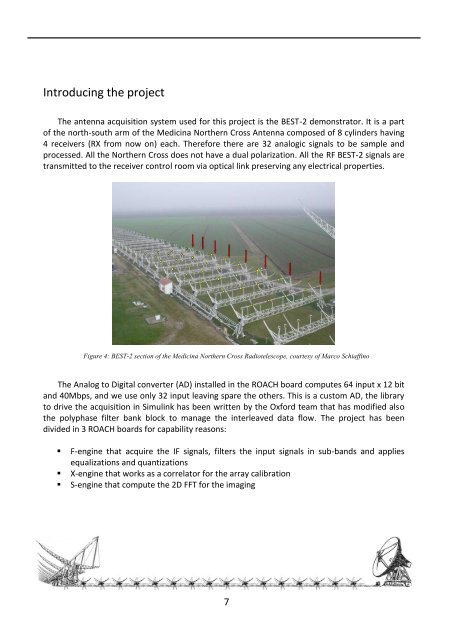
The antenna acquisition system used <strong>for</strong> this project is the BEST-2 demonstrator. It is a part<br />
of the north-south arm of the Medicina Northern Cross Antenna composed of 8 cylinders having<br />
4 receivers (RX from now on) each. There<strong>for</strong>e there are 32 analogic signals to be sample and<br />
processed. All the Northern Cross does not have a dual polarization. All the RF BEST-2 signals are<br />
transmitted to the receiver control room via optical link preserving any electrical properties.<br />
Figure 4: BEST-2 section of the Medicina Northern Cross Radiotelescope, courtesy of Marco Schiaffino<br />
The Analog to <strong>Digital</strong> converter (AD) installed in the ROACH board computes 64 input x 12 bit<br />
and 40Mbps, and we use only 32 input leaving spare the others. This is a custom AD, the library<br />
to drive the acquisition in Simulink has been written by the Ox<strong>for</strong>d team that has modified also<br />
the polyphase filter bank block to manage the interleaved data flow. The project has been<br />
divided in 3 ROACH boards <strong>for</strong> capability reasons:<br />
• F-engine that acquire the IF signals, filters the input signals in sub-bands and applies<br />
equalizations and quantizations<br />
• X-engine that works as a correlator <strong>for</strong> the array calibration<br />
• S-engine that compute the 2D FFT <strong>for</strong> the imaging<br />
7